LUNO GAS - Gas stove HASE - Free user manual and instructions
Find the device manual for free LUNO GAS HASE in PDF.
User questions about LUNO GAS HASE
0 question about this device. Answer the ones you know or ask your own.
Ask a new question about this device
Download the instructions for your Gas stove in PDF format for free! Find your manual LUNO GAS - HASE and take your electronic device back in hand. On this page are published all the documents necessary for the use of your device. LUNO GAS by HASE.
USER MANUAL LUNO GAS HASE
Dimensions de raccordement:
Egregio cliente Hase,
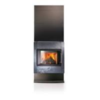
With your Hase Gas you have chosen a quality product. Handicraft tradition, an elegant design and the latest technology guarantee you years of joy and reliable service.
The body of the Gas fire consists of strong steel plates that have been produced using modern welding engineering. Heat-resisting stones in the fire chamber and heat-consistent special varnish guarantee stability and a long service life of all Hase models. We pay the greatest possible attention to top quality of all materials used, as well as highest possible care in workmanship. The Luno Gas is a room-air independent convection room heater with flame effect due to imitation glowing embers and imitation logs. It can be operated manually or via remote control. Temperature and time can only be set via the remote control.
To ensure the safest, most efficient and environmentally-friendly usage, we recommend following the safety notes and operating instructions for the gas fire.

Safety Notes:
If you smell gas:
- No open fires!
No smoking! - Avoid sparking! Do not use any electrical switches, including telephones, plugs and doorbell systems!
- Shut off main gas supply valve!
- Open windows and doors!
- Warn other occupants and leave building!
- Ring your gas utility company or specialised heating company from outside the building!

Attention:
Before you install and start using your gas appliance, please read these instructions carefully and keep this manual in a safe place, they will be required when servicing the appliance.
Before installation, the appliance should be checked for integrity. Professional installation by a competent person is required, and will ensure the appliance functions properly.
These instructions have been written in line with EN 613.
This appliance must only be used with the door secured in the closed position, and must not be used if any of the glass panels are cracked, broken or missing.
The outside of this appliance will get hot in use, it is therefore recommended that a suitable guard is erected if the appliance is used in the presence of children, elderly or infirm persons.
Do not attempt to burn rubbish in this fire, it is not intended as an incinerator.
Ensure that fabrics such as curtains are not positioned above or near to the outer casing of this appliance.
This appliance is designed as a heating appliance and as such all surfaces except the controls and the control access door are working surfaces, and thus get hot.
Inhalt
Technical Specifications - Natural Gas 59
Technical Specifications - Propane Gas 60
Technical Specifications - Dimensions 61
1. Important Safety Notice 62
2. Installation 63
2.1 General Fitting Information 63
2.2 Stove Location 63
2.3 Inserting / Replacing Batteries 63
2.4 Transport Aid 64
2.5 Ventilation 64
2.6 General Balanced Flue Notes 64
2.7 Concentric Flue Parts Identification 65
2.8 Gas Connection 65
2.9 Pressure Testing 66
2.10 Arranging The Ceramic Fire 66
2.11 Opening the Fire Box Door 67
2.12 Log Arrangement: Natural gas 67
2.13 Log Arrangement:Propane 67
2.14 Pebble Arrangement: Natural gas 68
2.15 Pebble Arrangement:Propane 69
2.16 Gravel Arrangement - Natural 69
2.17 Gravel Arrangement - Propane 69
2.18 Initial Operation 69
3. Servicing Instructions 70
3.1 Annual maintenance 70
3.2 Troubleshooting 70
4. Using The Appliance 71
4.1 Remote Control with Climate Control 71
4.2 Setting the Display 71
4.3 Setting the Current Time 71
4.4 Modes 71
4.5 Switching Modes 72
4.6 Setting the Temperature 72
4.7 Setting the Timer 72
4.8 Igniting the Stove 72
4.9 Extinguishing the Appliance Fully 73
Technical Specifications - Natural Gas
Injector Marking: 700, Efficiency class: 2, NOx: Unclassified
| Destination Country | Natural Gas | Supply pressure (mbar) | Burner pressure (mbar) | Nominal heat input (Hs;kW) | Gas flow rate (m3/h) | Classification |
| AT | G20 l2H | 20 | 14,6 | 9,1 | 0,854 | C11 / C31 |
| BE | G20/G25 l2E+ | 20/25 | 14,6 / 18,2 | 9,1 / 8,3 | 0,854 / 0,906 | C11 / C31 |
| CH | G20 l2H | 20 | 14,6 | 9,1 | 0,854 | C11 / C31 |
| DE | G20/G25 l2ELL | 20 | 14,6 | 9,1 / 7,3 | 0,854 / 0,803 | C11 / C31 |
| DK | G20 l2H | 20 | 14,6 | 9,1 | 0,854 | C11 / C31 |
| EE | G20 l2H | 20 | 14,6 | 9,1 | 0,854 | C11 / C31 |
| ES | G20 l2H | 20 | 14,6 | 9,1 | 0,854 | C11 / C31 |
| FI | G20 l2H | 20 | 14,6 | 9,1 | 0,854 | C11 / C31 |
| FR | G20/G25 l2E+ | 20/25 | 14,6 / 18,2 | 9,1 / 8,3 | 0,854 / 0,906 | C11 / C31 |
| GB | G20 l2H | 20 | 14,6 | 9,1 | 0,854 | C11 / C31 |
| GR | G20 l2H | 20 | 14,6 | 9,1 | 0,854 | C11 / C31 |
| IE | G20 l2H | 20 | 14,6 | 9,1 | 0,854 | C11 / C31 |
| IT | G20 l2H | 20 | 14,6 | 9,1 | 0,854 | C11 / C31 |
| LT | G20 l2H | 25 | 14,6 | 9,1 | 0,854 | C11 / C31 |
| LU | G20 l2E | 20 | 14,6 | 9,1 | 0,854 | C11 / C31 |
| LV | G20 l2H | 20 | 14,6 | 9,1 | 0,854 | C11 / C31 |
| NL | G20 l2L | 20 | 18,2 | 8,3 | 0,854 | C11 / C31 |
| NO | G20 l2H | 20 | 14,6 | 9,1 | 0,854 | C11 / C31 |
| PL | G20 l2E | 20 | 14,6 | 9,1 | 0,854 | C11 / C31 |
| PT | G20 l2H | 20 | 14,6 | 9,1 | 0,854 | C11 / C31 |
| SE | G20 l2H | 20 | 14,6 | 9,1 | 0,854 | C11 / C31 |
| SL | G20 l2H | 20 | 14,6 | 9,1 | 0,854 | C11 / C31 |
| SK | G20 l2H | 20 | 14,6 | 9,1 | 0,854 | C11 / C31 |
| TR | G20 l2H | 20 | 14,6 | 9,1 | 0,854 | C11 / C31 |
Technical Specifications - Propane Gas
Injector Marking: 220, Efficiency class: 2, NOx: Unclassified
| Destination Country | Propane Gas | Supply pressure (mbar) | Burner pressure (mbar) | Nominal heat input (Hs;kW) | Gas flow rate (m3/h) | Classification |
| AT | G31 I3P | 50* | 29,0* | 6,7 | 0,4 | C11 / C31 |
| BE | G31 I3P | 37* | 29,0* | 6,7 | 0,4 | C11 / C31 |
| CH | G31 I3P | 37* | 29,0* | 6,7 | 0,4 | C11 / C31 |
| CZ | G31 I3P | 30*/37*/50* | 29,0* | 6,7 | 0,4 | C11 / C31 |
| DE | G31 I3P | 50* | 29,0* | 6,7 | 0,4 | C11 / C31 |
| ES | G31 I3P | 37* | 29,0* | 6,7 | 0,4 | C11 / C31 |
| FR | G31 I3P | 37* | 29,0* | 6,7 | 0,4 | C11 / C31 |
| GB | G31 I3P | 37* | 29,0* | 6,7 | 0,4 | C11 / C31 |
| GR | G31 I3P | 30*/37*/50* | 29,0* | 6,7 | 0,4 | C11 / C31 |
| IE | G31 I3P | 37* | 29,0* | 6,7 | 0,4 | C11 / C31 |
| IT | G31 I3P | 37* | 29,0* | 6,7 | 0,4 | C11 / C31 |
| LT | G31 I3P | 30* | 29,0* | 6,7 | 0,4 | C11 / C31 |
| NL | G31 I3P | 30*/50* | 29,0* | 6,7 | 0,4 | C11 / C31 |
| PL | G31 I3P | 36* | 29,0* | 6,7 | 0,4 | C11 / C31 |
| PT | G31 I3P | 37* | 29,0* | 6,7 | 0,4 | C11 / C31 |
| SL | G31 I3P | 37* | 29,0* | 6,7 | 0,4 | C11 / C31 |
| SK | G31 I3P | 30*/37*/50* | 29,0* | 6,7 | 0,4 | C11 / C31 |
| TR | G31 I3P | 37* | 29,0* | 6,7 | 0,4 | C11 / C31 |
*Please note: for propane gas operation, the burner pressure has to be adjusted to the local conditions and requirements. The burner pressure is preset for a supply pressure of 30 mbar.
Technical Specifications - Dimensions
Stofe Luno Gas BF, certified in compliance with EG Guideline
90/396/EWG and DIN EN 613 (2000)
Product ID number: CE-0063BR5705
Construction Type: C_11^;C_51^
Combustion Values:
| Nominal Thermal Output (Natural Gas, Hs) | 6.9 kW |
| Nominal Heat Load (Natural Gas, Hs) | 9.1 kW |
| Nominal Heat Load (Natural Gas, Hi) | 8.2 kW |
| Nominal Thermal Output (Propane, Hs) | 5.0 kW |
| Nominal Heat Load (Propane, Hs) | 6.7 kW |
| Nominal Heat Load (Propane, Hi) | 6.0 kW |
Dimensions:
| Height | Width | Depht | |
| Stofe | 116 cm | 51 cm | 45 cm |
| Tile | Soapstone | ||
| Weight | 96 kg | 100 kg |
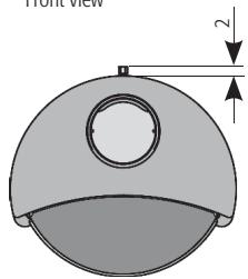
Connection Dimensions:
| Approved flue gas system: | ONTOP Metalterm Serie US Ø 100/150 | |
| Flue Pipe Connection Height: | 117 cm | |
| Gas Connection Height: | 19,5 cm | |
| Distance from back wall of stove to flue pipe centre: | 12,5 cm | |
| Distance from back wall of stove to the wall (Fixation to wall): | 20 - 30,5 cm | |
| Gas connection: | Ø 8, 12 mm compression | |
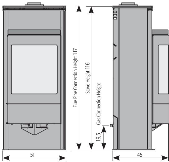
Front view
Top view
Side view
Fig. 1:Dimensions in cm
1. Important Safety Notice
This appliance has a ceramic Fire-bed arrangement; this contains Refractory Ceramic Fibres, which are man-made vitreous silicate fibres. Excessive exposure to these materials can cause irritation to eyes, skin and respiratory organs. Hence we recommend that when handling these materials the release of dust should be kept to a minimum. During installation and servicing we recommend that a HEPA filtered
vacuum be used to remove any dust and soot in and around the fire. If any of the ceramic fire-bed components need to be replaced we recommend that the removed parts be sealed in a heavy-duty polythene bag, and be labelled as RCF waste. RCF is not "Hazardous waste" and can be disposed of at a licensed tipping site for the disposal of industrial waste.
The appliance incorporates a permanent pilot. This is located on the front of the burner, and must not be adjusted by the installer. This system must not be put out of operation, and if any parts require changing, only original manufacturer parts shall be used.
This appliance is designed to be used either Natural or LPG gas however, each individual appliance is only capable of running off the type of gas specified at the time of purchase. It is important to note that once a type of gas has been specified the stove cannot run off any other type. The type of gas that your stove is capable of burning is stated on the data information panel.
This appliance has been designed, tested and approved to meet standards in place for product use, performance and safety. Installation of your Stove must comply with current building regulations.
This appliance is designed as an efficient heating device and consequently all body parts become very hot in use. Except for the control knob and swing door, which are designed to stay cool, all other parts are working surfaces and should not be touched.
Bearing in mind that the heat given off by this appliance may affect articles placed close to it, curtains should not be placed within 30cm .
The appliance is not designed as a dryer. It is not therefore recommended that the appliance be used in such a manner. Do not place any articles within 30cm of this appliance as this may result in damage to the articles.
The installation must be carried out in accordance with the following regulations:
- in Germany, the technical regulations for gas installation DVGW-TRGI1986 (issue 1996)
- in The Netherlands Algemene Gasinstallatievoorscriten (GAVO)NEN 1078
- in BE the NBN D51-003 and possibly local regulations
- in GB the British Standards BS 587Part 1 and 2, BS 5440 Parts 1 and 2,BS 6891, BS5871 part 1, and BS1251. In addition Building Regulations Document J and Building Regulations and standards issued as relevant by the Department of the Environment or the Scottish Development Department.
- in IE the installation should be performed in accordance with IS813,ICP3, IS327, Building Regulations, Codes of Practice, the manufacturer's instructions and any rules inforce.
The above list may not be comprehensive, but failure to comply with all local and national regulations could leave the installer liable to prosecution.
Before installation, check that this appliance is compatible with local distribution conditions, nature of gas and pressure. The technical specification of this appliance is given on the first pages of this manual.
2. Installation
2.1 General Fitting Information
Inlet pipe connection
8 mm, 12mm compression
Chimney requirements
Balanced Flue
Flue monitor
Permanent Pilot
NOx - Level
see technical specifications at beginning of manual
Approved flue gas system
Metaloterm Ontop Serie US 0 100/150
Before installation of these appliances, the area into which the fire is to be fitted must be cleared of all debris (including dust), in particular combustible material.
Failure to comply with the instructions in this manual, or the regulations and standards could have hazardous consequences.

2.2 Stove Location
These appliances are designed with the "Firebox" raised up off the ground level by the built in "Base unit".
Thus these appliances require no special Hearth arrangements, as the floor will not get hot and is protected by the steel construction of the "Base unit".
If the appliance has to be located in an opening, a minimum clearance of 5cm should be allowed to non-combustible materials.
The stove must be located at least 30 cm from any combustible materials.
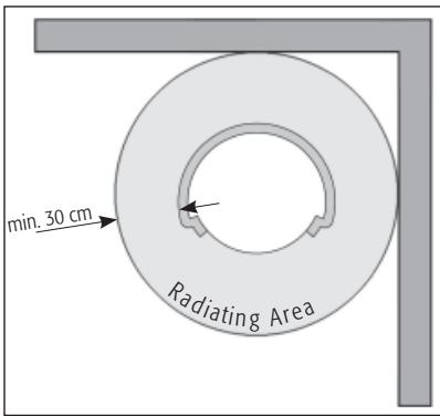
Fig. 2
2.3 Inserting / Replacing Batteries
An audible signal (three short beeps) indicates that the batteries need to be replaced.
To insert or replace the batteries of the receiver, remove the lock screw and pull out the receiver (see Figure 3, 4). Open the battery compartment cover and insert the batteries, then push the receiver back in and secure it with the lock screw.
Battery type
Receiver: 4x AA, R6 size. Alkaline only
Transmitter: PP3 (Alkaline only).
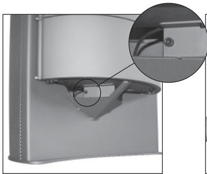
Fig. 3
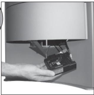
Fig. 4
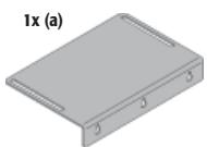
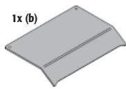
2.4 Transport Aid
Fig.5 Unscrew transport aid (a); Attention: Rescrew the screws (b) into position in the body of the stove, as they serve as the level adjustment for the tile or soapstone shelf cover
Fig. 6 For moving with a push-truck, place the transport aid (a) into the upper slit in the rear wall of the stove
Fig. 6 To lift the stove, place the transport aid (a) into the lower slit in the rear of the stove
2.5 Ventilation
Balanced Flue appliances can be installed into a house without the need for additional ventilation. They can also be installed into a room that has a forced mechanical ventilation and/or fume extraction without any special extra requirements.
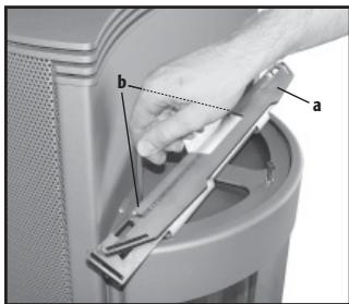
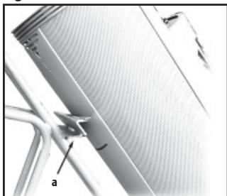
Fig. 5
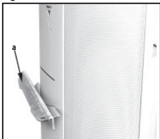
Fig. 6
Fig. 7
2.6 General Balanced Flue Notes
There are many possibilities for installing this Concentric
Balanced Flue system into a building, both Roof and Wall terminations are possible, and the flue can either be built into an existing chimney or a completely new flue system may be constructed.
The system is based upon a Concentric Flue system which utilises an inner flue of 10cm diameter which passes through an outer flue of 15cm diameter. The flue gasses that are the products of combustion of the fire, pass through the inner flue and are safely vented to the outside environment. The gap between the inner and outer flues is the channel by which the stove is supplied with air for combustion.
These concentric flues terminate outside of the property in a terminal, this terminal will keep the expelled gasses and the fresh air for combustion separate. It is important that the terminal is not blocked, a suitable guard maybe required if the terminal is located at a "Low" level (usually when the terminal is within 2m of floor level).
If an existing Flue or Chimney is to be utilised, then the installation engineer must be consulted. If the chimney has been previously used it must be professionally cleaned and certified as being sound and fit for use.
The European CE approval on this appliance is restricted to the Flue systems as specified by the supplier, thus the appliance must only be installed with the original flue system, no others may be used.
Timber Frame Construction
Whilst it is possible to install room-sealed appliances in timber frame properties, great care needs to be taken to ensure that the flue assembly does not interfere with the weather proofing qualities of any outer wall which it may penetrate. Before attempting this work, further details need to be referenced, (e.g. "Gas Installations in Timber Frame Buildings" from the CORGI installer series in the UK).
Carport or Building Extension
Where a flue terminal is sited within a carport or building extension, it should have at least two completely open and unobstructed sides. The distance between the lowest part of the roof and the top of the terminal should be at least 60~cm .
Note: A covered passageway should not be treated as a carport.
Basements, Lightwells and Retaining walls
Flue terminals should not be sited within the confines of a basement area, light well or external space formed by a retaining wall, unless steps are taken to ensure the products of combustion can disperse safely at all times. It may be possible to install this Balanced Flue system in such a location provided that it is not sited lower than 1m from the top level of that area to allow combustion products to disperse safely.
2.7 Concentric Flue Parts Identification
The appending pages identify the parts that may be used in the Balanced Flue installation of this appliance.

Important note for Roof Terminations (_31)
When installing the appliance with a roof termination (classification C31), it is important to fit a 3 cm flue restriction strip (a) across the flue outlet inside the stove (Fig. 8, 9). Luno on LPG is an exception to this, and does not require the restrictor.
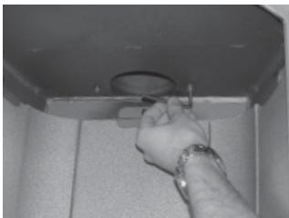
Fig. 8
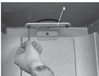
Fig. 9
2.8 Gas Connection
Please make absolutely sure that all pipings are installed and fitted in compliance with the applicable national regulations. A minimum pipe size of 15mm should be used for the gas supply to within 1 metre of the appliance. 8mm pipe may only be used for the final connection to the stove, or within 1 meter of the appliance. An 8mm nut and olive is supplied with the stove for the final pipe joint.
A gas supply tap must be installed in the supply pipe work in a location that is easily accessible, such that the appliance may be isolated if necessary.
Do not make any connections to the appliance until all supply pipes have been purged to expel any dust or debris. Failure to do this may result in a blocked injector or tap and will invalidate the guarantee. Although a gas soundness test is made on all appliances before they leave the factory, the appliance should be tested for soundness before operating the stove. This is to ensure that the burner has not been damaged in transit.
If thestove is connected with a rigid pipe, it is imperative to attach it firmly to its floor position.
2x (c)

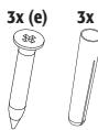
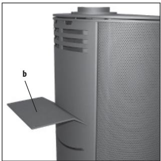
Fig. 10
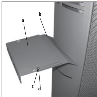
Fig. 11
Attach mounting bracket (a) to spacer plate (b) using disk (e) and screw (d) (Fig. 11).
Move stove into proper position. Fasten mounting bracket (a) to wall using dowel (g) and screw (f) (Fig. 11).
Distance from back wall of stove to the wall (Fixation to wall) : 20 - 30,5 cm
2.9 Pressure Testing
The gas pressure to the burner must be measured; this should be measured with all gas appliances after the gas meter operating on full, including this stove.
2.10 Arranging The Ceramic Fire
Only the ceramics supplied with this appliance are to be used. The ceramics must be laid only as shown on the following pages. Replacement parts including mat are available from your dealer, but should only be installed by a qualified installation engineer.
2.11 Opening the Fire Box Door
Loosen the hexagonal socket screws at the top and bottom (a, b) of the fire box door. The door opens to the left side (Fig. 12, 13).
To close and lock the fire box door again, position the supplied lever (c) as shown in Figure 21. Push the fire box door closed, insert the upper hexagonal socket screw (a) and tighten it. Then tighten the hexagonal socket screw at the bottom (b) (Fig. 15).
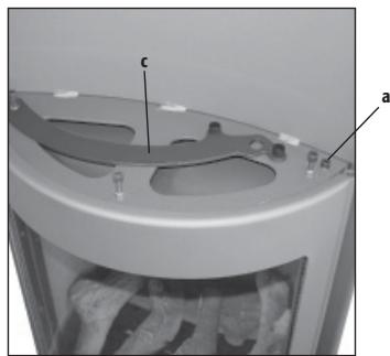
Fig. 12
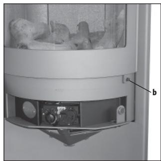
Fig. 13
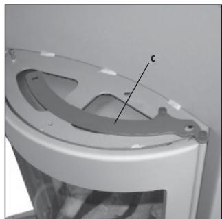
Fig. 14
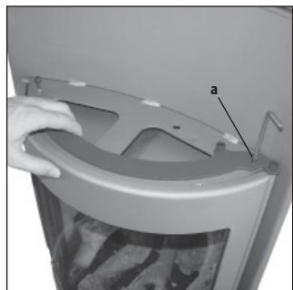
Fig. 15
2.12 Log Arrangement: Natural gas
1/2 bag of Embers, 6 ceramic logs
Procedure: First place the Mat on top of the Burner and place the grate plate on top of the Mat and Burner.
Lay the large log on top of the grate at the rear of the firebox (Fig. 16).
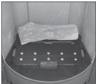
Fig. 16
Scatter the contents of the bag of embers on top of the burner and grate, these should be evenly spread, ensuring that the pilot is not impinged, and that no embers enter the Pilot Shield (Fig. 17).
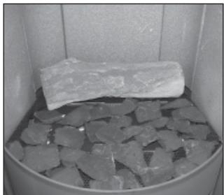
Fig. 17
Place the four intermediate logs, so that rear of each is sitting on top of the large log and the opposite end of each log is lying towards the front of the fire.
Lay the final small log at the very front of the fire box, positioned so that it is in front of the Pilot shield (Fig. 18).
The Pilot flame must be left visible when lit.
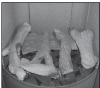
Fig. 18
2.13 Log Arrangement: Propane
1/2 bag of Embers, 6 ceramic logs
Procedure: First place the Mat on top of the Burner and place the grate plate on top of the Mat and Burner.
Lay the large log on top of the grate at the rear of the firebox.
Scatter the contents of the bag of embers on top of the burner and grate, these should be evenly spread, ensuring that the gas ports are left clear, the pilot is not impinged, and that no embers enter the Pilot Shield (Fig. 19).
Place the larger two of the four intermediate logs, so that rear of each is sitting on top of the large log and the opposite end of each log is lying towards the front of the fire, one at each end of the burner, these two logs should be touching the sides of the firebox (Fig. 20).
Place the remaining two intermediate logs so that the rear end is lying on top of the rear log and is touching the rear of the firebox. The opposite end of the logs should be sitting on the centre of the burner. Ensure that the gas ports are left clear.
Lay the final small log at the very front of the fire box, positioned so that it is in front of the Pilot shield (Fig. 21).
The Pilot flame must be left visible when lit.
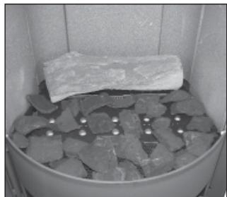
Fig. 19
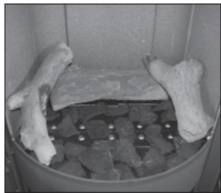
Fig. 20
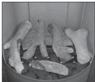
Fig. 21
2.14 Pebble Arrangement: Natural gas
1 bag containing 26 pebbles.
Procedure: First place the Mat on top of the Burner and place the grate plate on top of the Mat and Burner.
Place 3 pebbles across the rear of the Firebox, with an additional pebble at the two extremities of the burner (Fig. 22).
Place 2 pebbles, longitudinally along the centre of the burner (Fig. 23).
Place 4 pebbles around the front of the grate (Fig. 24).
Place 2 pebbles on top of the very back 2 pebbles, so that they are touching the back of the Firebox, a further 2 pebbles are placed between the end pebble and the corner pebble, one at each end (Fig. 25).
5 more pebbles are then placed between the front to rows in place (Fig. 26).
Place 2 pebbles behind the central row of pebbles, located in between the 3 pebbles at the rear of the arrangement (Fig. 27).
Position another 3 pebbles along the centre of the arrangement, sitting between the pebbles along the centre of the burner and the row along the rear of the burner.
The last pebble will now sit on top of the arrangement, and can be sat either on the Right hand side or the Left hand side at the rear of the arrangement (Fig. 28).
Ensure that the Pilot flame is still visible.
The arrangement is now complete.
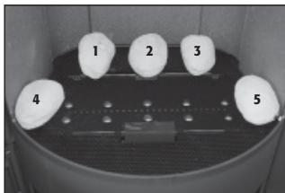
Fig. 22
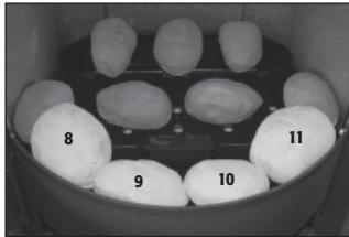
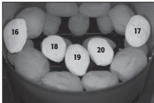
Fig. 24
Fig. 26
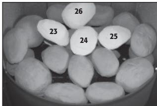
Fig. 28
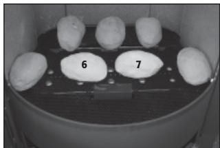
Fig. 23
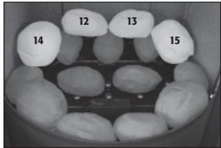
Fig. 25
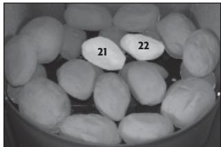
Fig. 27
2.15 Pebble Arrangement: Propane
1 Procedure: First place the Mat on top of the Burner and place the grate plate on top of the Mat and Burner.
Place 3 pebbles across the rear of the Firebox, with an additional pebble at the two extremities of the burner (Fig. 22).
Place 2 pebbles, longitudinally along the centre of the burner (Fig. 23).
Place 4 pebbles around the front of the grate (Fig. 24).
Place 2 pebbles on top of the very back 2 pebbles, so that they are touching the back of the Firebox, a further 2 pebbles are placed between the end pebble and the corner pebble, one at each end (Fig. 25).
5 more pebbles are then placed between the front to rows in place (Fig. 26).
Place 2 pebbles behind the central row of pebbles, located in between the 3 pebbles at the rear of the arrangement. Position another 3 pebbles at the very rear of the firebox, on top of the rear row (Fig. 29).
The last pebble will now sit in the middle of the arrangement, on top of the 2 pebbles placed on top of the burner in the last stage (Fig. 30).
Ensure that the Pilot flame is still visible.
The arrangement is now complete.
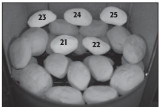
Fig. 29
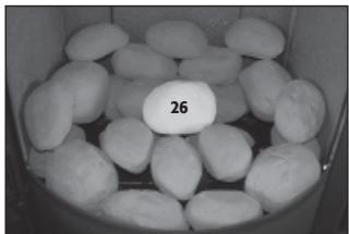
Fig. 30
2.16 Gravel Arrangement - Natural
1 bag of Gravel
Procedure: First place the Mat on top of the Burner and place the grate plate on top of the Mat and Burner.
Scatter the contents on the Bag of Gravels over the top of the Mat and Grate area.
Care is needed so that none of the Gravels enter the Pilot shield, this area must be kept clear and impinged (Abb. 38).
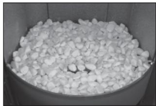
Fig. 31
2.17 Gravel Arrangement - Propane
1 bag of Gravel
Procedure: First place the Mat on top of the Burner and place the grate plate on top of the Mat and Burner.
Scatter the contents on the Bag of Gravels over the top of the Mat and Grate area, leaving the Gas ports clear.
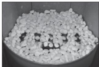
Fig. 32
Care is needed so that none of the Gravels enter the Pilot shield, this area must be kept clear and the cross lighting to the main burner not impinged (Abb. 39).
2.18 Initial Operation
A soundness test MUST be made before the installed stove is left with the customer.
Ensure that the fire is burning at full rate for a minimum of 5 minutes to warm the flue.
If there are problems, the chimney/flue may require attention. Isolate the stove and seek expert advice.
The stove will produce an odour and/or smoke for the first few hours of use. Please ventilate the room.
When the stove is operated for the first time, additional white residue may form on the ceramic glass panels in the interior. This residue is non-toxic and can be removed with a conventional glass cleaner.
3 Servicing Instructions
3.1 Annual maintenance
The following outlines only the minimum work that should be performed on an annual basis. This service work, like any other work on the appliance, must only be done by a qualified and competent engineer.
- Open the door and remove all ceramics.
- Remove mat from top of burner.
- Remove any debris from the top of the burner using a vacuum cleaner and brush.
- Inspect the burner unit.
Perform an ignition check.
Perform a flame failure check - There should be no need to service the burner. If however this is required, then the engineer should check the setting pressure at inlet to burner; the correct pressure is shown at the front of the manual.
- Brush off and replace ceramic arrangement as earlier in this manual, replacing any broken or damaged pieces.
- Check all seal on door (including glass) and replace the Door.
- Check the installation for gas leaks.
- Check flue for clearance of products of combustion.
If any parts need to be replaced use only genuine Hase parts, non-standard parts will invalidate the guarantee and may be dangerous.
Spares list
Use only genuine manufacturer supplier replacement parts.
- Burner Mat
Control Tap (BF) - Injector Natural (BF)
- Injector LPG (BF)
Pilot Natural (BF)
Pilot LPG (BF)
Glass window
3.2 Troubleshooting
The gas pilot will not ignite or stay lit?
Ensure the gas is turned on at the appliance and the meter/cylinder.
Ensure that the pilot injector is not obstructed or blocked and it is free from any dust or dirt.
Ensure that the thermocouple has not been damaged in transit. This is a very delicate Electro-magnetic device.
On propane, the cylinder could be empty.
You may need to repeat the ignition sequence several times.
The pilot is not burning or performing correctly?
Ensure the pilot flame is the correct size for the type of gas. The flame should be focused on the thermocouple probe.
The pilot flame will have been set correctly in the factory.
The Main Burner does not seem to be burning correctly?
Ensure adequate gas pressure to the appliance. Test pressure by releasing the pressure test screw and applying a manometer. Ensure adequate volume of gas is being used. Once the fire is burning on maximum, turn off all other gas appliances in the house and calculate the fuel being burned from the gas meter. Make sure that the burner is burning correctly. The flame should be even across the top of the burner before any coals are placed on top.
4. Using The Appliance
It is very important to read these instructions thoroughly before lighting.
This appliance will produce an odour and/or smoke for the first few hours of use when new. Please ventilate the room when first lighting from new.
There is a monitoring system fitted to this appliance, which cuts off the gas supply upon the detection of a blocked flue. If this system activates and the appliance cuts out, allow 3 minutes before retrying the ignition, noting that the control tap must first be returned to the off position. If the pilot will not light, allow a further 3 minutes or sufficient time for switch to reset. If cutting off persists, then a professionally qualified engineer should be informed.
The control panel is located behind the swing door below the fire box door; it is equipped with a magnetic lock and can be easily pulled open (Fig. 33). The standard control is a basic rotary tap, which has a single control knob. As an optional extra a remote control version is available which has two rotary control knobs. The remote control version must be specified
at time of ordering All versions of this appliance operate with a traditional pilot light. The pilot light is located in the centre of the burner, and is visible through the front window. If the Flame Supervision Device Actuating Flame (the Pilot Light) is extinguished either by intention or not, no attempt should be made to re-light until 3 minutes have elapsed.
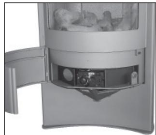
Fig. 33
4.1 Remote Control with Climate Control
4.2 Setting the Display
Simultaneously pressing OFF and switches from the Fahrenheit (°F)/12-hour clock to the Celsius (°C)/24-hour clock and vice versa.
4.3 Setting the Current Time
After inserting the battery or by simultaneously pressing and , the display starts flashing. You are now in set mode.
In set mode, press to set the hour and to set the minutes.
Wait for a short time or press OFF to return immediately to manual mode.
4.4 Modes
MAN: Mode for manual flame height adjustment (stove in standby mode).
Press to ignite the main burner or increase the flame height. Press to decrease the flame height or activate standby mode (permanent pilot). To incrementally increase or decrease the flame height, repeatedly lightly tap the or button.
The "Send" icon appears in the upper right corner of the display when either button is pressed.
- TEMP: Daytime temperature control mode (automatic)
TEMP: Nighttime temperature control mode (automatic)
A sensor in the transmitter measures the room temperature.
The receiver then compares the room temperature to the preset temperature and adjusts the flame height as necessary.

TIMER: Timer mode
During heating periods P1 and P2, the temperature is controlled in the same manner as in automatic mode.
If the timer switches to (heating cycle off), the actuating motor sets the valve to standby (permanent pilot) and the temperature control is deactivated, which minimises battery consumption.
In order to maintain automatic temperature control in the mode as well, the temperature must be set to 4^ or higher.
4.5 Switching Modes
Pressing the SET button cycles through the various modes in the following sequence:
MAN *TEMP DTEMP TIMER and back to MAN
From any mode, press or to return immediately to manual mode.
4.6 Setting the Temperature
Press the SET button until the TEMP or TEMP modes are displayed.
Hold the SET button until the temperature display starts flashing. Press or to set the desired temperature.
4.7 Setting the Timer
Press the SET button until the TIMER mode is displayed. Hold the SET button until the timer display starts flashing. Set the start time for heating period 1 (P1*) by pressing to set the hour and to set the minutes.
Press the SET button again to set the end time for heating period 1 (P1D).
Pressing the SET button once again lets you set the times for heating period 2 (P2*P2). If you only want to program one heating period, simply enter identical times for P1*/P1 and P2*/P2).
Once all times are set, press OFF to store the values.
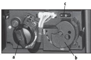
4.8 Igniting the Stove
Prior to starting the ignition process, the left control knob (a) must be turned to the "OFF" position and the right control knob (b) must be turned to the "ON" position. Furthermore, the ON/OFF switch must be activated.
Simultaneously press the OFF and buttons of the receiver for ignition.
An acoustic signal indicates that the start sequence has begun.
The electronic system then checks that the main gas is flowing and ignites the main burner; this may take up to 20 seconds.
You may need to repeat the ignition sequence several times.
Please note:
Once the pilot flame ignites, the motor automatically sets the main burner to maximum flame height.
Using the remote control, you now can operate the stove in one of the modes described above.
4.9 Extinguishing the Appliance Fully
From any heat setting, press the OFF button for a few seconds. This will cause the burner to fully extinguish.
The system has a safety interlock which will not allow the Ignition until the Interlock rests (this may take a few minutes).