AKABA - Wood stove HASE - Free user manual and instructions
Find the device manual for free AKABA HASE in PDF.
| Product type | Wood stove |
| Brand | HASE |
| Model | AKABA |
| Dimensions (H x W x D) | 111.5 cm x 41 cm x 41 cm |
| Weight | 118 kg |
| Nominal heat output | 4 kW |
| Recommended fuel | Natural wood logs (moisture < 20%) |
| Energy efficiency | 82% |
| CO rate (at 13% O₂) | 1221 mg/m³ |
| Fine particles | 34 mg/m³ |
| Flue gas temperature at the flue pipe | 350 °C |
| Flue gas mass flow | 4 g/s |
| Minimum back pressure | 10 Pa (Akaba Standard) / 12 Pa (recommended) |
| Flue pipe diameter | 120 - 150 mm (recommended 150 mm) |
| Hase air system diameter | 100 mm (for room air independent version) |
| Air supply | Primary air (bottom) and secondary air (top), manually adjustable |
| Safety distance (front) | 80 cm from flammable materials |
| Safety distance (sides/rear) | 20 cm |
| Floor protection | Mandatory if floor is flammable (tiles, slate, etc.) |
| Cleaning the steel casing | Slightly damp cloth (acid-free) |
| Cleaning the glass | Cold ash and newspaper |
| Maintenance of flue pipes | Annually, after the heating season |
| Spare parts | Only original Hase parts (seals, thermal stones, paint) |
| Certifications | DIN EN 13240, Art. 15a B-VG (Austria), VKF No. 15107 |
Frequently Asked Questions - AKABA HASE
User questions about AKABA HASE
0 question about this device. Answer the ones you know or ask your own.
Ask a new question about this device
Download the instructions for your Wood stove in PDF format for free! Find your manual AKABA - HASE and take your electronic device back in hand. On this page are published all the documents necessary for the use of your device. AKABA by HASE.
USER MANUAL AKABA HASE
Chere cliente, Cher client,
Egregi clienti Hase,
In deciding on a Hase stove, you have purchased a top quality product. In our stove factory in Trier, Germany, we develop and manufacture our stoves with the utmost care and precision, using only premium-quality materials. Harmonious design, state-of-the-art production methods as well as efficient and environmentally friendly combustion technology guarantee that you can enjoy your Hase stove for many years to come.
We hope you will enjoy your new Hase stove.
- Installation Conditions and Relevant Building Regulations 70
- Safety and Safety Distances 70
- Installation 71
3.1 Akaba Standard 71
3.2 Akaba direct vent stove 71
- The Chimney 71
4.1 Akaba Standard 71
4.2 Akaba direct vent stove 71
- Flue Pipe Connection 72
5.1 Akaba Standard 72
5.2 Akaba direct vent stove 72
- Combustion Air Connection (Akaba direct vent stove) 72
- Butterfly Valve 72
- Fuel Load Sizes and Thermal Output 73
9.Regulating the Combustion Air 73
9.1 Primary Air 73
9.2 Secondary Air 73
-
Initial Operation 74
-
Lighting the Fire 74
- Adding Fuel (Wood) 75
- Heating at Low Thermal Output 75
- Emptying the Ash Analyzer 76
- The Combustion Process 76
15.1 Drying Phase 76
15.2 Degasification Phase 76
15.3 Burn-off Phase 76
15.4 Expansion Noises 77
- The Right Fuel 77
- The Chemistry of Wood 77
- Contribution to Environmental Protection 77
- Evaluating the Combustion Quality 78
- Wood Moisture Content and Calorific Value 78
- Storing and Drying Wood 79
- Cleaning and Maintenance
Page
22.1 Steel Cladding 79
22.2 Flue Gas Paths 79
22.3 Ceramic Glass Panels and Windows 79
22.4 Fire Box Lining 79
22.5 Sealing Strips 80
Useful tips 81
Technical Data 82
Socket variations (Akaba direct vent stove) 85
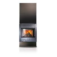
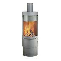
Akaba Standard
Akaba direct vent stove
1. Installation Conditions and Relevant Building Regulations
The stove must be installed in accordance with the instructions and requirements stipulated by the respective national and European standards and local regulations. In Germany, the stove must be registered with the local master chimney sweep for inspection prior to initial operation.
2. Safety and Safety Distances
At the front and sides of the stove, no flammable, combustible or heat-sensitive materials (e.g. furniture, wood or plastic panelling, curtains, etc.) are to be located within a distance of 80~cm in the heat radiating area of the fire box window. In regards to flammable materials beyond the heat radiating area, a safety distance of 20~cm at the sides of and behind the stove has to be adhered to (see Fig. 3).
Children should never be left unattended near the burning stove.
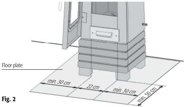
In accordance with the German Combustion Ordinance Draft, flammable flooring materials (wood, laminate, carpeting,) must be protected with a floor plate made of non-combustible material (tiles, safety glass, slate or sheet steel).
Never use spirits, petrol or other flammable fluids to light the stove. During operation, the external surfaces of the stove become very hot, thus the entire stove poses a burn hazard. To ensure the safe operation of this stove, a glove is included in the scope of delivery.
In case of a chimney fire:
- Ring the emergency telephone number to alert the fire brigade.
- Notify your chimney sweep.
- Never extinguish the fire with water!
- Remove any flammable objects located in the vicinity of the chimney.
- Wait for the fire brigade and chimney sweep to arrive.
Modifying or making changes to the stove is not permitted. Only original replacement parts from Hase Kaminofenbau GmbH may be used.
When using a floor plate, the safety distances stipulated apply.
Distances to Heat-sensitive and Combustible Materials
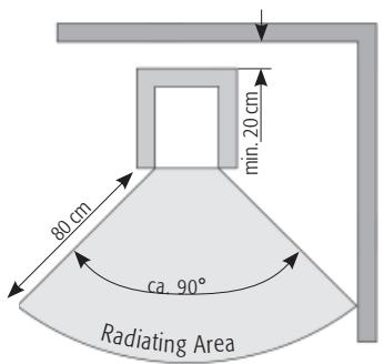
Fig.3 Layout for Wall Location
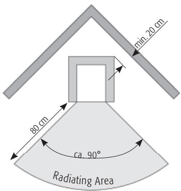
Layout for Corner Location
3. Installation
3.1 Akaba Standard
Check to make sure that the load-bearing capacity of the floor / installation surface is sufficient. If necessary, using a floor plate to distribute the load can increase the load-bearing capacity.
In addition, check whether the room in which the Akaba Standard is to be installed is sufficiently supplied with fresh air. If the windows and doors are tightly sealed, the necessary supply of fresh air may not be ensured, which can interfere with the draught capability of the stove and chimney. If additional combustion air inlet openings are required, they are not permitted to be closed or obstructed.
Simultaneous operation of the stove and the exhaust hood can cause negative pressure to build up in the room where the stove is installed, which can lead to problems such as flue gas escaping from the stove.
To ensure that air is not drawn out of the room where the stove is installed, we recommend locking exhaust hoods that guide the air to the outside by means of a window contact switch.
3.2 Akaba direct vent stove
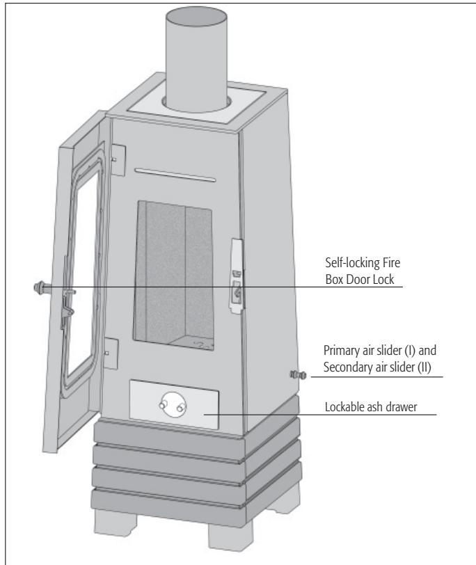
The door of the Akaba direct vent stove is self-locking. To ensure that the self-locking mechanism functions
perfectly, use the spirit level to precisely align the Akaba direct vent stove in a horizontal position. The stove can be aligned by means of four levelling feet (see Assembly and Maintenance Instructions).
Please make sure that there is sufficient ventilation in the room where the Akaba direct vent stove will be installed.
For rooms with a cubic volume of more than 50m^3 , an hourly air exchange ratio of
1.5 is required. With smaller rooms, the air change rate needs to be higher. The negative pressure in the room where the stove is installed is not permitted to
exceed the value of 8 Pascal (the ventilation system designer specifies the air pressure in Pascal units). We recommend setting the ventilation system to a maximum negative pressure of 4 Pascal. To ensure that no air is drained from the room, we recommend operating exhaust hoods in recirculation air mode or using a window contact switch to lock exhaust hoods that guide air to the outside.
4. The Chimney
4.1 Akaba Standard
The Akaba Standard has to be connected to a suitable chimney with a minimum effective chimney height of 4.50m . It can be connected to a chimney to which other fireplaces are already connected. The chimney cross section should correspond to the flue pipe cross section. If the effective chimney height is too low and/or the chimney cross section is too large or too small, the draught capability of your stove can be impaired.
The Akaba Standard stove requires a 12 Pa output pressure (chimney draft). At higher output pressures, the stove emissions increase, which puts a high load on the stove and can lead to damage. The Akaba Standard stove has a maximum permissible output pressure of 35 Pa.
To limit the output pressure, a butterfly valve or output pressure limiter can be used.
4.2 Akaba direct vent stove
The Akaba direct vent stove needs its own separate chimney.
The draught capability of your stove can be impaired by a chimney cross section that is too large or too small and/or an effective chimney height of less than 4.50m . The "effective chimney height" is the distance between the flue gas intake in the chimney and the top of the
chimney pot. After a soot fire in the chimney, the impermeability (air-tightness) of the flue gas paths has to be checked.
We recommend connection to a multi-leaf chimney with a cross-section having a maximum diameter of 160mm and a minimum n effective chimney height of 4.5m .
If these specifications cannot be met, we advise you to check the suitability of the chimney by means of a chimney calculation.
5. Flue Pipe Connection
5.1 Akaba Standard
The Akaba has to be connected to the chimney with a flue pipe having an inside diameter of 120mm - 150mm . Please ensure a tight fit of all pipe pieces at the connection junctions. The pipe must be well sealed in the chimney entrance and cannot project into the inner cavity of the chimney; otherwise the flue venting will be impaired.
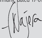
5.2 Akaba direct vent stove
The Akaba direct vent stove has to be connected to the chimney with a flue pipe having an inside diameter of 120mm - 150mm . The flue pipe has to be sealed at the flue pipe connection piece with Hase
Sealing Paste.
The flue pipe connection to the chimney has to be gas proof and sealed with a suitable sealing cord and heat-resistant silicone (see Fig. 7). The flue pipe cannot project into the cross-section of the chimney, as that can impair flue venting.
We recommend using a one-piece flue pipe. The total length of the connecting pipe between the stove and the chimney should not exceed 1.50m .
6. Combustion Air Connection ( Akaba direct vent stove )
The combustion air in the fire box is solely supplied by a customer-provided supply air pipe and the Hase Air System pipe connections. The connecting piece for the Hase Air system is located on the back side of the stove. The sealed pipe connections are either routed directly to the outside or connected to a suitable air/flue gas system (AFS). Another option is to provide the supply air from a room with its own independent outside air supply (e.g. cellar or basement) (see Figs. 7 - 9).
For the customer-provided installation of the air inlet, plain pipes (steel pipes in compliance
with 24145, drain pipes in accordance with DIN 19534 and EN 1451B) with a minimum diameter of 100mm , a maximum of two bends and a permissible total length of 5 meters should be used. Verification by calculation is required for longer piping and more than two bends.
The air supply pipe has to be equipped with an inspection opening for inspecting and cleaning purposes. The entire air supply pipe has to be airtight.
We advise discussing this with your local planning officer.
At the air inlet opening, we recommend installing an animal protection screen with a mesh size of 10mm .
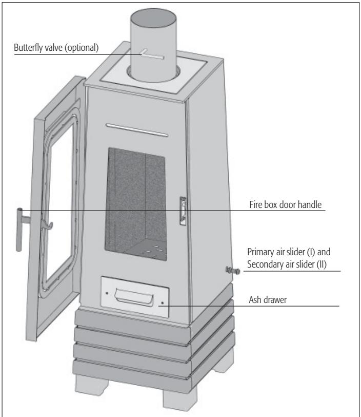
7. Butterfly Valve ( Akaba Standard )
The butterfly valve is an optional control element. It is fitted in the flue pipe and used to regulate the flue gas flow, and can thus slow down the burning-off process. When the handle's position is diagonal to the flue pipe, the flue gas flow rate is turned to minimum. We strongly recommend the installation of a butterfly valve to reduce the output pressure. Please consider the country-specific statutory regulations.
8. Fuel Load Sizes and Thermal Output
The thermal output depends on the amount of fuel you burn in the stove (fuel load size). When adding more fuel (e.g. wood), the maximum fuel load size is 1kg . Exceeding the maximum fuel load size leads to a danger of overheating, possibly resulting in damage to the stove and risk of a stove fire.
A thermal output of 4kW can be attained by burning wood logs weighing approx. 0,8kg and approx. 20cm in length for approx. 40min .
To attain thermal output of 2,5kW , burn wood logs weighing approx. 0.3kg and approx. 20cm in length for approx. 20min .
The Akaba is intended for intermittent operation, please only apply one fuel layer at a time.
9. Regulating the Combustion Air
When lighting the fire and adding fuel, the combustion air is regulated with the primary air and secondary slider.
9.1 Primary Air
The primary air is guided through the grate and into the fire box from below, thus more quickly achieving the required fire box temperature during the warming up phase.
9.2 Secondary Air
The secondary air is guided into the fire box via air ducts from the top. It supplies the fire box with the volume of preheated oxygen necessary to completely burn off the wood gas and ensures that the fire box window remains free of soot.
For regulating the secondary air, the following general rule applies: a small fire requires little secondary air; a large fire requires ample secondary air.
If the secondary air valve is closed too tightly, there is the risk of the flue gases not completely burning (smouldering fire) and/or soot build-up on the fire box window or that the amassed wood gases will burn explosively (over firing/deflagration).
Please note: Burning wood when the primary air slider is opened too wide poses the risk of overheating the stove (forge fire effect). During operation, the secondary air slider should never be completely closed. The fire box door and ash compartment must always be tightly shut.
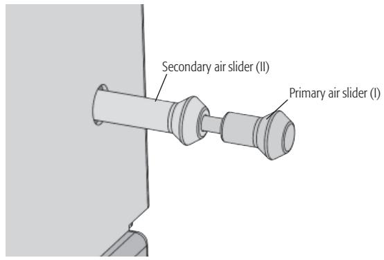
Fig. 4 The control elements are located on the lower right side.
10. Initial Operation
The first time you operate a stove, smoke and odours can develop as organic components in the coating, sealing strips and lubricants used in the production process burn off.
At a higher combustion temperature, this one-time process can take between 4 to 5 hours. To achieve this higher combustion temperature, please increase the fuel quantity recommended in Section 12, Adding Wood or Fuel, by approximately 25% .
To prevent adverse effects on health, nobody should stay in the room(s) where the stove is being operated unless absolutely necessary. Make sure the room is well-ventilated and open the windows and outside doors. If needed, use a fan for faster air circulation.
If the maximum temperature isn't reached during the first heating operation, you may notice an odour for a short period of time during subsequent operations as well.
During shipment to you, condensation moisture can accumulate in the stove's interior, which may possibly lead to the appearance of condensation or water on the stove or flue pipes.
Please dry off these damp areas immediately.
The surface of your stove was degreased in a sandblasting machine before being lacquered. Despite careful and thorough inspection, there may still be some blasting material (small steel pellets) in the stove body, which can fall out when your stove is being installed.
To prevent any damage, please immediately vacuum up these little steel pellets with a vacuum cleaner.
The Akaba may only be operated when the fire box door is closed; the fire box door may only be opened to add fuel.
11. Lighting the Fire
The firing up phase should be as short as possible, since higher emission value rates can occur during this phase.
The slider settings described in Table 1 are recommendations that were determined under testing conditions, in compliance with the relevant standard.
Depending on the weather conditions and the draught capability of your chimney, accordingly adjust the slider positions for your Akaba to the local conditions.
Lighting the Fire
Tab. 1
| Procedure | Position of Control Elements |
| Completely open primary and secondary air. | Pull primary and secondary air sliders all the way out. |
| Open fire box door. | |
| Pile up any remaining ash and unburned Charcoal into the centre of the combustion chamber. | |
| Place ignition material into the middle of the fire box; stack approx. 0.5 kg of dry wood chips on top. | |
| Light the ignition material at several places. | |
| Close fire box door. | |
| As soon as the wood chips begin to completely burn, place two wood logs (approx. 0.5 kg total weight) with the small side facing forward. |
12. Adding Fuel (Wood)
More fuel (wood) should be added to the fire during the burning off phase, when the flames from the previous burning off phase have just gone out.
When stoking the fire, open the fire box door very slowly to minimise the emergence of flue gases and prevent ashes from swirling up in the fire box.
Adding Fuel (Wood)
Tab. 2
| Procedure | Position of Control Elements |
| Completely open primary and secondary air. | Pull primary and secondary air sliders all the way out. |
| Open fire box door. | |
| Add a log weighing approx. 0.8 kg with the small side facing forward. Place logs with the bark facing upwards or outwards. Only add a single layer of fuel (wood). | |
| After igniting the log, close the primary air and completely open the secondary air. | Push in primary air slider as far as it will go. Pull out secondary air slider as far as it will go. |
| Close fire box door. |
13. Heating at Low Thermal Output
The thermal output of your Akaba stove is primarily affected by the quantity of fuel used.
Do not attempt to slow down the combustion by reducing the air supply.
When heating with wood, this can result in an incomplete burning process and pose the risk of explosive-like combustion of the accumulated wood gases (deflagration).
Heating at Low Thermal Output
Tab. 3
| Procedure | Position of Control Elements |
| Close primary air. | Push in primary air slider (I) as far as the secondary air slider allows. |
| Completely open secondary air. | Pull out secondary air slider as far as it will go. |
| Add a log (approx. 0.3 kg) with the small side facing forward. |
GB
14. Emptying the Ash Analyzer
For safety's sake, please make sure that you only dispose of ashes once they are cold. While the ash collects, the lid is located under the ash drawer.
Unlock the ash drawer. Remove both the ash drawer and the lid located underneath it. Slide the lid onto the ash drawer so that it is closed; this prevents ashes from flying around, which in turn means your home stays clean. To place the ash drawer back into the stove, proceed in the reverse order.
Piled up ashes can prevent or even block the primary air supply to the stove. Ensure that the ventilation path for the primary air between the ash drawer and the bottom of the ash compartment remains clear.
15. The Combustion Process
A piece of wood burns in three phases. In a wood fire, however, these processes take place both consecutively and simultaneously
15.1 Drying Phase
The moisture still remaining in the air-dried wood (approx. 15 - 20%) is evaporated. This takes place at temperatures of approx. 100^ . For the evaporation to occur, the wood must be supplied with heat during the warming up phase; this is achieved by using small wood logs.
15.2 Degasification Phase
At temperatures of between 100^ and 150^ , the contents of the wood start (slowly at first) to disintegrate and gasify and the wood begins its thermal decomposition. At temperatures above 150^ , the gas development increases strongly. The proportion of volatile components makes up around 80% of the wood substance.
At a temperature of about 225^ (ignition temperature), the actual combustion begins with the ignition of the resulting gases and the release of heat. There must be an adequate supply of oxygen available for this purpose. The peak of the combustion process is reached at approx. 300^ . The reaction process is now so rapid that the largest amount of heat is
released at this point; flames can reach temperatures of up to 1100^ .
15.3 Burn-off Phase
Glowing charcoal embers remain after the volatile components have been burned off. These burn slowly, almost without flames, at a temperature of approx. 800^ .
Crucial to a clean and efficient combustion process is a complete (as possible) chemical reaction of the wood gases with the oxygen in the combustion air. With your Hase stove, the combustion air is pre-heated and guided into the fire box via wide air inlet openings, enabling a good and thorough mixing of the gases with the air. An important variable in any combustion phase is the amount of combustion air.
Not enough air leads to an oxygen deficiency and incomplete combustion, while too much air reduces the fire box temperature and thus the efficiency. Incomplete combustion can
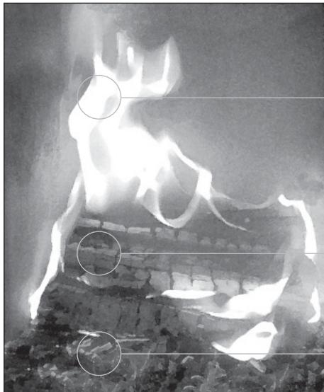
Degasification
Drying
Burn-off
Fig. 5 The Combustion Process
generate air pollutants such as dust, carbon monoxide and hydrocarbons.
15.4 Expansion Noises
Steel expands upon heating and contracts as it cools, which can cause your stove to emit audible expansion sounds. However, the design and construction of your stove takes this into account and prevents this physical process from damaging the stove.
16. The Right Fuel
Only fuels which generate low quantities of smoke may be burned in stoves. For the Akaba, only natural, untreated, beechwood logs, including the adherent bark, can be used as fuel. Highly resinous coniferous wood (e.g. spruce, pine, fir) tends to emit flying sparks and leaves behind a fine layer of flue ash that can swirl up when the fire box door is opened.
For the most attractive stove fire, use beech wood logs. If other types of wood are used, such as oak, birch, pine or larch, we recommend adding beech wood for picturesque dancing flames. Brushwood and small pieces of wood are good kindling materials.
he burning of e.g.:
- damp or moist wood (residual moisture content over 20% )
- varnished or plastic-coated wood,
- wood treated with wood preservatives,
household waste, or - paper briquettes (pollutants: cadmium, lead, zinc)
- any flammable fluids (including methanol and ethanol) as well as any fuel pastes or gels is not permitted.
Combustion of the materials listed above not only gives off unpleasant odours, but also generates emissions that damage the environment and are harmful to health.
17. The Chemistry of Wood
Wood predominantly consists of the elements carbon, hydrogen and oxygen. It contains virtually no environmentally hazardous substances such as sulphur, chloride and heavy metals. As a result, complete wood combustion produces mainly carbon dioxide and water vapour as the primary gaseous products as well as a small quantity of wood ash as the solid combustion residue.
On the other hand, incomplete combustion can generate a number of pollutant substances, such as carbon monoxide (toxic), acetic acid, phenols, methanol (toxic), formaldehyde, soot and tar.
18. Contribution to Environmental Protection
Whether your Akaba burns in an environmentally-friendly or environmentally hazardous manner depends to a large extent on how you operate it and the type of fuel you use (see "The Right Fuel").
Use only dry wood; hardwoods such as birch and beech are most suitable
Only use small pieces of wood to light the fire. They burn faster than large logs and thus the temperature required for complete combustion is reached more quickly.
For continual heating, adding smaller quantities of wood more frequently is more efficient and more ecological.
19. Evaluating the Combustion Quality
The following characteristics can facilitate easy evaluation of the combustion quality:
Colour and composition of the ash
If the combustion process is efficient, the result is a fine white ash. Dark colouration indicates that the ash contains charcoal residue; in this case, the burn-off phase was incomplete.
- The colour of the flue gases emitted at the chimney pot
In this respect, the following applies: the more invisible the flue gases exiting the chimney, the better the combustion quality.
During the transitional seasons (spring/autumn), outdoor temperatures above 16^ can impair the chimney draught. If a draught cannot be created at these temperatures by rapidly burning paper or thin wood shavings (quick fire), you should refrain from lighting the stove.
20. Wood Moisture Content and Calorific Value
Rule of thumb: the more damp the wood, the lower the calorific value
The calorific value of the wood depends largely on the wood moisture content. The more moisture the wood contains, the more energy expended to evaporate it during the combustion phase; this energy is then lost. Thus, the more damp the wood, the lower its calorific value.
An example: freshly cut wood has a moisture content of approx. 50% and a calorific value of around 2.3kWh / kg ; in contrast, wood which has been efficiently air-dried has a moisture content of approx. 15% and a calorific value of around 4.3kWh / kg .
Accordingly, if you burn very moist wood, you will have about half the thermal output with the same quantity of wood. Furthermore, burning moist wood results in substantial soot build-up on the fire box window.
Moreover, when moist wood is burned, the resulting water vapour can condense in the flue pipe or chimney. This can lead to a build up of shiny soot on the chimney or chimney
creosote. In addition, if the wood has a high moisture content, the combustion temperature decreases, which prevents complete combustion of all the wood components and causes considerable environmental pollution.
You can use a wood moisture meter to determine the residual moisture content of your firewood.
21. Storing and Drying Wood
Wood needs time to dry. If stored properly, it will air-dry in approx. 2 to 3 years.
Saw, split and store the wood ready for use; this ensures rapid drying because smaller pieces of wood dry better than larger, uncut logs.
Stack and store your wood logs in a ventilated and as sunny as possible location, ideally facing south, and ensure that they are protected from rain.
Leave a hand's width between the individual piles of wood so that air can flow between them and carry away any escaping moisture.
Do not cover your stacks of wood with plastic sheeting or tarpaulins; otherwise the moisture cannot escape.
Do not stack fresh wood in a cellar or basement, since it will rot rather than dry due to the lack of airflow.
Only store already dried wood in dry and wellventilated cellar or basement rooms.
22. Cleaning and Maintenance
22.1 Steel Cladding
Hase stoves are coated with a heat-resistant open porous lacquer that provides only limited corrosion protection; accordingly, a rust film may develop in some cases.
Do not use any detergents containing acid (e.g. citrus or vinegar cleaners) to clean the steel parts. The steel parts can be sufficiently cleaned by wiping them down with a slightly moistened cloth.
Avoid using excessive water to clean the floor/floor plate areas.
Spilt water from kettles, boilers or water tanks should be immediately mopped up.
Do not install the Akaba in „damp rooms“, e.g. conservatories or enclosed porches. Avoid temporary storage in unheated building shells or garages.
Treat areas covered in a rust film with the original Hase Stove Lacquer Spray. Be sure and follow the instructions on the spray can. Your authorised Hase specialist dealer stocks the stove lacquer spray and can give you tips on using it.
22.2 Flue Gas Paths
The stove and flue pipes should be inspected for sediment and deposits at the end of each year's heating period (even more often if required, e.g. after the chimney has been cleaned), and cleaned if necessary.
To clean the flue gas paths, lift out the upper heat-resisting stone from the fire box. Any soot or dust sediment / deposits can be brushed off and vacuumed away. Then re-insert the heat-resisting stone.
Use a flexible pipe brush to clean the flue pipe at the cleaning port located on the flue pipe.
22.3 Ceramic Glass Panels and Windows
When the stove is properly operated, the secondary air simultaneously forms an air curtain at the pane, which prevents the glass from becoming sooty.
If ash particles get on the ceramic glass panels, we recommend, as an alternative to conventional glass cleaners, a tried and true environmentally-friendly cleaning method:
Take some balled-up paper towelling or newspaper, moisten it, dip it into the cold wood ash, rub the panel with it and then wipe the glass with a clean, dry ball of paper.
22.4 Fire Box Lining
The heat-resisting stones in your stove's fire box are made of Vermiculite. Vermiculite is a fire-resistant mineralogical granulate material with excellent insulating properties. The density of the slabs is a result of the optimal balance between mechanical stability and insulation properties.
The relatively soft surface is subject to natural wear and tear, depending on use. The heat-resisting stones have to be replaced if parts break off and the back wall of the fire box, located behind the slabs, becomes visible. Tears or cracks in the heat-resisting stones do not impair the functioning of your stove.
To reduce the damage to the heat-resisting stones, place logs carefully in the fire box and do not let them fall against the walls of the fire box.
22.5 Sealing Strips
The sealing strips for the fire box door and ash box are made of highly heat-resistant, asbestos-free fibreglass. The sealing strips are wearing parts and thus have to be replaced in line with the frequency of use.
We advise having your stove regularly inspected by a specialist.
For more information, please refer to the Assembly and Maintenance Instructions.
| Possible Problem | Possible Cause |
| The wood does not light or lights only slowly. | - The wood is too thick. / The wood is too damp. - The air supply is insufficient. |
| The wood burns without a bright, yellow flame, smoulders or even goes out. | - The wood is too damp. - The air supply is insufficient. - The outside temperature is too high. |
| Too much soot is generated; the heat-resisting stones do not stay clean and free of soot during operation. | - The wood is too damp. - The air supply is insufficient. - The quantity of wood is too small and thus the combustion chamber remains too cold. |
| The fire box window becomes sooty. | - The wood is too damp. - The secondary air supply is insufficient. - The fire box door is not tightly sealed. - The chimney draught is too weak. |
| The wood burns off too quickly. | - The chimney draught is too strong. - The wood logs are too small. - The control elements are incorrectly positioned or set. |
| Smoke escapes into the room while the stove is in operation. | - The air supply is insufficient. - The chimney cross section is too narrow. - The flue gas ducts in the stove pipe or chimney are extremely sooty. - Wind is blowing down on the chimney. - Fans (bathroom, kitchen) are creating negative pressure in the living room and drawing smoke from the stove. |
| The chimney becomes wet and coated with creosote, condensate leaks out of the stove pipe. | - The wood is too damp. - The flue gases are too cold. / The chimney is too cold. - The chimney cross section is too wide. |
| Smoke escapes when the fire box door is opened. | - The chimney draught is too weak. / The chimney cross section is too wide or too narrow. - The fire is still burning too strongly. - The fire box door was opened too rapidly. - Fans (bathroom, kitchen) are creating negative pressure in the living room and drawing smoke from the stove. |
Akaba Standard
The Akaba, certified in compliance with DIN-EN 13240: 2001 + A2 2004 and Art. 15 a B-VG (Austria), can only be operated when the fire box is closed; more than one device can be connected to the chimney.
VFK-No.: 15107; Inspection Report No. (A): FSPS-Wa-1366-A
Akaba direct vent stove
The Akaba direct vent stove, certified in compliance with DIN-EN 13240, DIN 18897-1 and Art. 15 a B-VG (Austria), can only be operated when the fire box is closed; needs its own separate chimney.
VFK-No.: 15107; Inspection Report No. (A): FSPS-Wa-1366-A
Conforms with the DIBT (Deutschen Institut für Bautechnik/German Institute for Building Technology) approval criteria for direct vent fireplaces for solid fuels.
The following data applies to the chimney characteristics in accordance with EN 13384-1 / 2:
| Combustion Values | Wood | |
| Nominal Thermal Output | 4 | kW |
| Waste Gas Mass Flow Rate | 4 | g/s |
| Waste Gas Outlet Temp. | 350 | °C |
| Min. Supply Pressure at Nominal Thermal Output | 10 | Pa |
| CO content at 13% O2 | 1221 | mg/m3 |
| Efficiency | 82 | % |
| Particulate | 34 | mg/m3 |
| Required combustion air volume at a max. supply pressure of 4Pa | 11 | m3/h |
Depending on the insulation of the building, the nominal thermal output of 4 kW indicated on 10 - 50 m² (subject to change)
Dimensions:
| Height | Width | Depth | |
| Stove | 111.5 cm | 41 cm | 41 cm |
| Fire box | 43 cm | 20 cm | 26 cm |
| Weight | 118 kg |
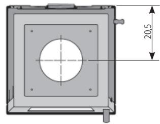
Connections:
| Height for top installation | 108 cm |
| Height for the inst. of Hase air system* | 37,5 cm |
Fire Box Opening 775 cm²
Flue pipe diameter 15 cm
Pipe diameter of Hase ventilation system* 10 cm
- For separate air supply in low-energy houses and insufficient combustion air supply in the room where the stove is installed (Akaba direct vent stove)
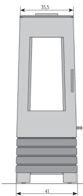
Front view
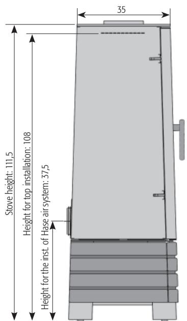
Side view
Top view
Fig. 6 Dimensions in cm
CE Declaration of Conformity
Hereby declares that the room heating appliance for use
with solid fuels, bearing the trade name:
Akaba
complies with the stipulations and provisions of the:
CE Construction Products Directive 89/106/EEC and the M129 Mandate
and is in compliance with the following harmonised standard:
EN 13240:2001+EN 13240:2001/A2:2004
The notified testing institute listed below has performed the inspection and testing of the room heating appliance for use with solid fuels in regards to conformity with the requirements specified by the standard:
RWE Power AG
Trier, Germany. dated 17-01-2011
Fernando Najera Executive Manager
Please observe the safety notes and precautions contained in the installation and operating instructions that are shipped with the product.
Socket variations Akaba direct vent stove
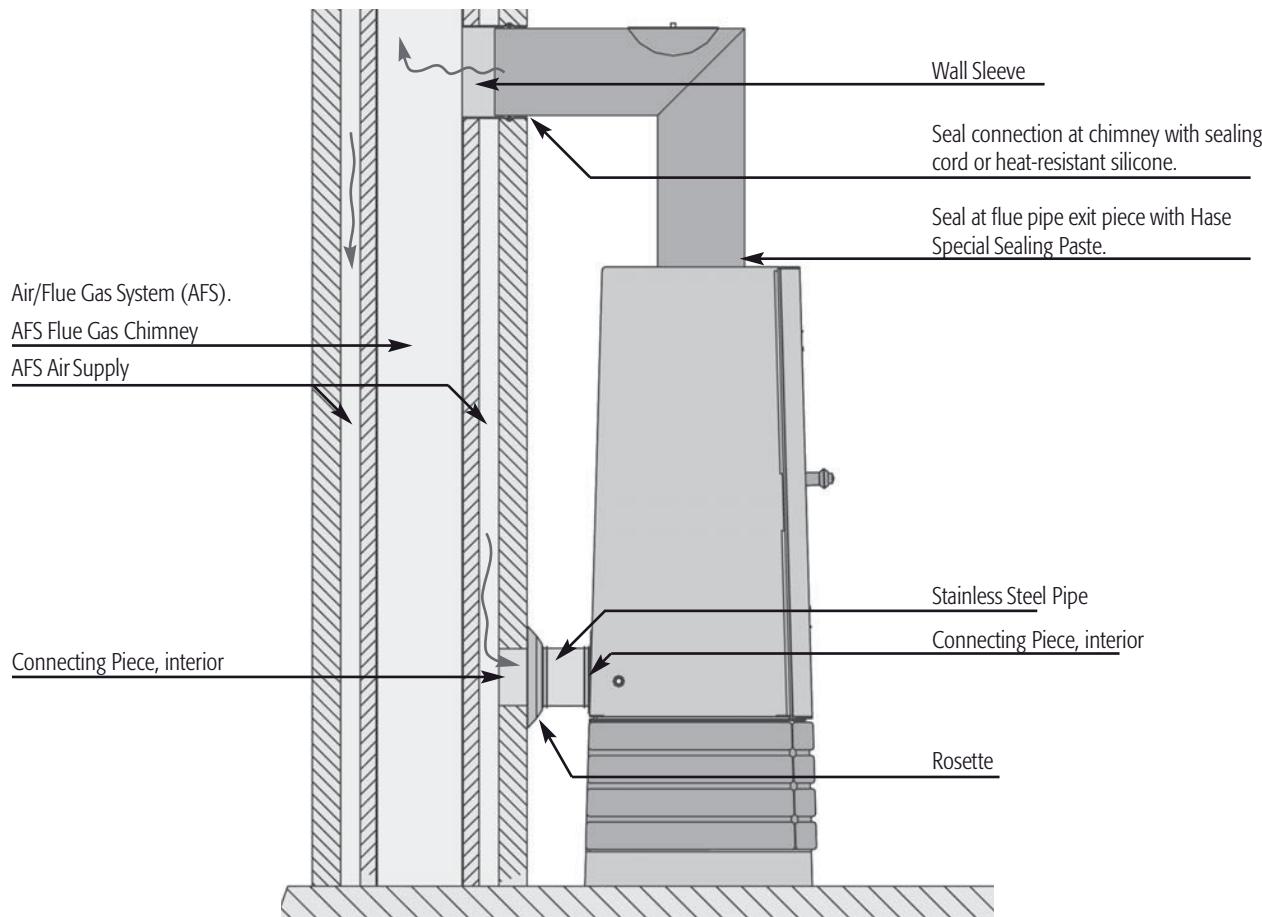
Fig. 7 Connection to an Air/Flue Gas System (AFS)
Fig. 8 Connection to an Air Supply Pipe.
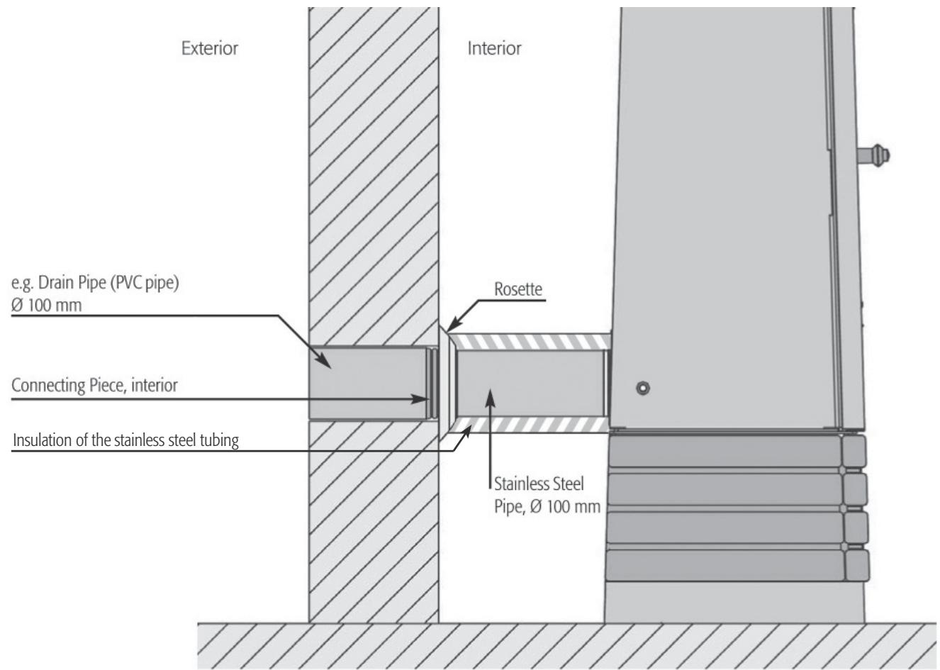
Fig. 9 Connection to an Air Supply Pipe
GB