
RC-1090 - Amplifier ROTEL - Free user manual and instructions
Find the device manual for free RC-1090 ROTEL in PDF.


| Product type | Stereo preamplifier |
| Brand | Rotel |
| Model | RC-1090 |
| Dimensions (W x H x D) | 430 x 125 x 345 mm |
| Weight | 7.8 kg |
| Power supply | 230 V, 50 Hz (Europe) |
| Maximum power consumption | 13 watts |
| Inputs | Phono (MM/MC), CD (balanced XLR and unbalanced RCA), Video, Tuner, Aux, Tape 1, Tape 2 |
| Outputs | RCA (2 pairs), balanced XLR, 6.35 mm headphone jack |
| Remote control | RR-969 universal |
| Main functions | Volume control, source selection for playback and recording, MUTE mode, customizable FL display, 12 V trigger, IR input/output, computer I/O port |
| Cleaning | Dry cloth or vacuum cleaner |
| Installation precautions | 10 cm free space around the device for ventilation, away from heat sources |
| Safety | Do not open the casing, do not expose to moisture, unplug before cleaning, use only the supplied power cord |
| Maintenance | No user-serviceable parts, contact an authorized Rotel service center for any repairs |
| Warranty | Keep the purchase invoice as proof of purchase date |
Frequently Asked Questions - RC-1090 ROTEL
User questions about RC-1090 ROTEL
0 question about this device. Answer the ones you know or ask your own.
Ask a new question about this device
Download the instructions for your Amplifier in PDF format for free! Find your manual RC-1090 - ROTEL and take your electronic device back in hand. On this page are published all the documents necessary for the use of your device. RC-1090 by ROTEL.
USER MANUAL RC-1090 ROTEL
This symbol is to alert the user to the presence of uninsulated dangerous voltages inside the product's enclosure that may constitute a risk of electric shock.

This symbol is to alert the user to important operating and maintenance (service) instructions in this manual and literature accompanying the product.
WARNING: There are no user serviceable parts inside. Refer all servicing to qualified service personnel.
WARNING: To reduce the risk of fire or electric shock, do not expose the unit to moisture or water. Do not allow foreign objects to get into the enclosure. If the unit is exposed to moisture, or a foreign object gets into the enclosure, immediately disconnect the power cord from the wall. Take the unit to a qualified service person for inspection and necessary repairs.
Read all the instructions before connecting or operating the component. Keep this manual so you can refer to these safety instructions.
Heed all warnings and safety information in these instructions and on the product itself. Follow all operating instructions.
Clean the enclosure only with a dry cloth or a vacuum cleaner.
You must allow 10 cm or 4 inches of unobstructed clearance around the unit. Do not place the unit on a bed, sofa, rug, or similar surface that could block the ventilation slots. If the component is placed in a bookcase or cabinet, there must be ventilation of the cabinet to allow proper cooling.
Keep the component away from radiators, heat registers, stoves, or any other appliance that produces heat.
The unit must be connected to a power supply only of the type and voltage specified on the rear panel of the unit.
Connect the component to the power outlet only with the supplied power supply cable or an exact equivalent. Do not modify the supplied cable in any way. Do not attempt to defeat grounding and/or polarization provisions. Do not use extension cords.
Do not route the power cord where it will be crushed, pinched, bent at severe angles, exposed to heat, or damaged in any way. Pay particular attention to the power cord at the plug and where it exits the back of the unit.
The power cord should be unplugged from the wall outlet if the unit is to be left unused for a long period of time.
Immediately stop using the component and have it inspected and/or serviced by a qualified service agency if:
- The power supply cord or plug has been damaged.
- Objects have fallen or liquid has been spilled into the unit.
- The unit has been exposed to rain.
- The unit shows signs of improper operation
- The unit has been dropped or damaged in any way
Place the unit on a fixed, level surface strong enough to support its weight. Do not place it on a moveable cart that could tip over.

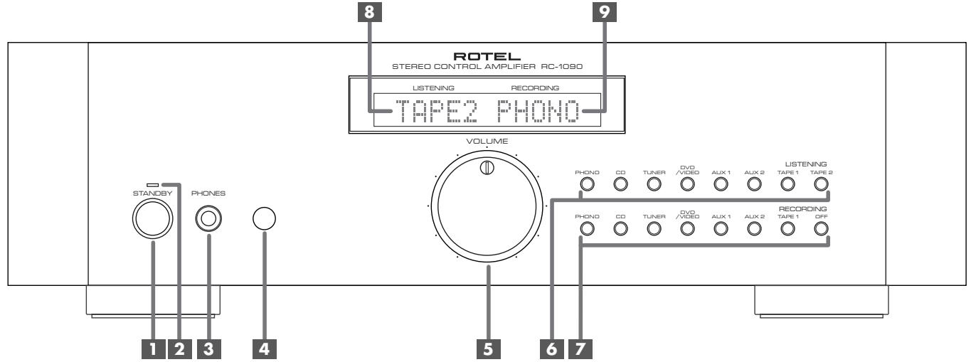
Figure 1: Controls and Connections

Figure 2: RR-969 Remote Control
Telecommande RR-969
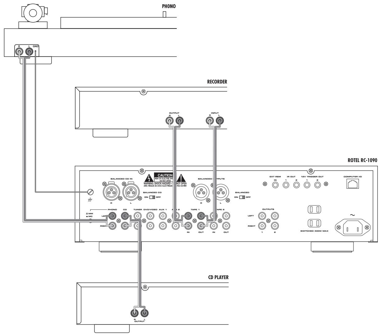
Figure 3: Phono and Line Inputs; Recorder Input/Output
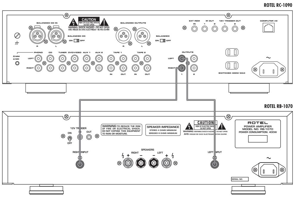
Figure 4: RCA Cable Connections Sorties via cable RCA Cinch-Anschlusse Collegamenti del Cavo RCA Conexiones No Balanceadas (RCA) De cinch uitgangen
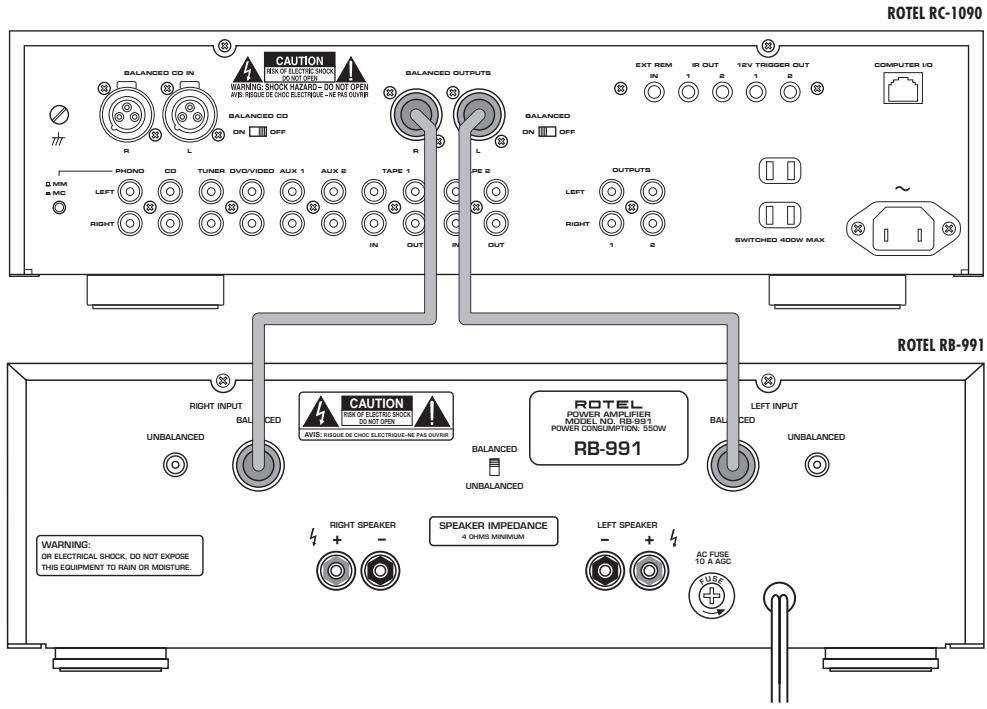
Figure 5: XLR Cable Connections Sorties via cable XLR XLR-Anschlisse Collegamenti del cavo XLR Conexiones Balanceadas (XLR) De XLR uitgangen
Contents
Figure 1: Controls and Connections 3
Figure 2:RR-969 Remote Control 3
Figure 3:Phono and Line Inputs; Recorder Input/Output 4
Figure 4: RCA Cable Connections 5
Figure 5: XLR Cable Connections 5
About Rotel 6
Getting Started 6
A Few Precautions 7
Placement 7
Cables 7
RR-969 Remote Control 7
Using the RR-969 A 7
Controlling Other Components B 7
Programming the RR-969 M 7
AC Power and Control 7
AC Power Input 7
Power/Standby Switch 1, Remote Power
Button and Power Indicator 2 8
Auxiliary Power Outputs 8
Input Signal Connections 12 and 13 ....8
Phono Input Selector Switch 8
Phono Input 12 and Ground 10 Connection 8
Line Level Inputs 13 8
Balanced CD Selector Switch 19 and Input 18 8
Recorder Connections 14 9
Output Connections 9
Balanced Output Switch 21 9
RCA Outputs 15 9
Balanced XLR Outputs 20 9
12 Volt Trigger Outlet 24 9
IR Inputs and Outputs 9
External Remote Input 22 9
IR Output 23 9
Computer I/O Connector 25 9
Audio Controls 10
Volume Controls 5 and D 10
Listening Selector Buttons 6 and Display 8 10
Recording Selector Buttons 7 and Display 9 10
10
Remote Sensor 4 10
Remote Control Functions 10
Selecting Listening Input 10
Selecting Recording Input 1 K 10
Mute Button E 10
FL Display Control 10
Turning FL Display On/Off L 10
Customizing FL Display F G H 10
Clearing FL Display Customization 11
Troubleshooting 11
Standby Power Indicator Is Not Lit 11
Fuse Replacement 11
No Sound 11
Specifications 11
About Rotel
A family whose passionate interest in music led them to manufacture high fidelity components of uncompromising quality founded Rotel 40 years ago. Over the years that passion has remained undiminished and the goal of providing exceptional value for audiophiles and music lovers regardless of their budget, is shared by all Rotel employees.
The engineers work as a close team, listening to, and fine tuning each new product until it reaches their exacting musical standards. They are free to choose components from around the world in order to make that product the best they can. You are likely to find capacitors from the United Kingdom and Germany, semi-conductors from Japan or the United States, and toroidal power transformers manufactured in Rotel's own factory.
Rotel's reputation for excellence has been earned through hundreds of good reviews and awards from the most respected reviewers in the industry, who listen to music every day. Their comments keep the company true to its goal - the pursuit of equipment that is musical, reliable and affordable.
All of us at Rotel thank you for buying this product and hope it will bring you many hours of enjoyment.
Getting Started
Thank you for purchasing the Rotel RC-1090 Stereo Control Amplifier. When used in a high-quality music audio system, it will provide years of musical enjoyment.
The RC-1090 is a full featured, high performance preamplifier. All aspects of the design have been optimized to retain the full dynamic range and subtle nuances of your music. The RC-1090 has a highly regulated power supply incorporating a Rotel custom-designed toroidal power transformer and custom-made slit foil capacitors. This low impedance power supply has ample power reserves, which enables the RC-1090 to easily reproduce the most demanding audio signals. This type of design is more expensive to manufacture, but it is better for the music.
The RC-1090 has both XLR (balanced) and RCA cable main output and CD input connections. The printed circuit boards (PCB) are designed with Symmetrical Circuit Traces. This insures that the precise timing of the music is maintained and faithfully recreated. The RC-1090 circuitry uses metal film resistors and polystyrene or polypropylene capacitors in important signal paths. All aspects of this design have been examined with the final goal being faithful reproduction of music.
The RC-1090 has a superb phono preamp stage, derived from Rotel's finest phono preamplifier, the RHQ 10. The preamp stage can be used with either a moving magnet (MM) or a moving coil (MC) phono cartridge. This shows our commitment to phono sound quality and our interest in the recreation of fine music.
The RC-1090 is straightforward in its installation and operation. If you have experience with other stereo systems, you shouldn't find anything perplexing. Simply plug in the associated components and enjoy.
A Few Precautions
Please read this manual carefully. It provides complete information on how to incorporate the RC-1090 into your system as well as general information that will help you get optimum sound performance. Please contact your authorized Rotel dealer for answers to any questions you might have. In addition, all of us at Rotel welcome your questions and comments.
Save the RC-1090 shipping carton and all enclosed packing material for future use. Shipping or moving the RC-1090 in anything other than the original packing material may result in severe damage to your amplifier.
Fill out and send in the owner's registration card packed with the RC-1090. Also be sure to keep the original sales receipt. It is your best record of the date of purchase, which you will need in the event warranty service is ever required.
Placement
Like all audio components that handle low-level signals, the RC-1090 can be affected by its environment. Do not stack the RC-1090 on top of a power amplifier. This will minimize chance it will pick up hum or interference. We recommend installing the RC-1090 in furniture designed to house audio components. Such furniture is designed to reduce or suppress vibration which can adversely affect sound quality. Ask your authorized Rotel dealer for advice about component furniture and proper installation of audio components.
Cables
Be sure to keep the power cords, digital signal cables and regular audio signal cables in your installation away from each other. This will minimize the chance of the regular audio signal cables picking up noise or interference from the power cords or digital cables. Using only high quality, shielded cables will also help to prevent noise or interference from degrading the sound quality of your system. If you have any questions see your authorized Rotel dealer for advice about the best cable to use with your system
RR-969 Remote Control
The RC-1090 includes a full-function learning remote control that can operate up to nine other components, in addition to the RC-1090.
A separate manual, included with the remote, gives detailed instructions on programming and using the RR-969 to replace all of the remote controls in your system. To avoid duplication, we provide only basic information about using the RR-969 to operate the RC-1090.
Most of the RR-969 functions duplicate the front panel controls. In this manual the remote control functions are covered in the same section as the front panel control operation. Numbers in gray boxes such as 1 indicate items on the front and rear panel control and connection illustrations. See Figure 1 on page 3. Letters in gray boxes such as A indicate items on the RR-969 illustration. See Figure 2 on page 3.
Using the RR-969 A
To operate the RC-1090 with the remote, activate the AUDIO mode, if necessary, by pressing the AUD button A. The AUDIO mode will remain selected until another DEVICE button is pressed.
Controlling Other
Components B
To control other components with the RR-969, press the appropriate Device Selection button. See the RR-969 manual for more information.
Programming the RR-969 M
The RR-969 is pre-programmed to operate the RC-1090. Should the AUDIO mode of the RR-969 not operate the RC-1090, the programming may have been changed. To restore the original programming, press the recessed Preload button on the remote with the tip of a ball point pen.
NOTE: Pushing the PRELOAD button will erase all custom programming and learned commands, restoring the RR-969 to its factory settings.
AC Power and Control
AC Power Input 17
Connect the supplied power cord to the AC Input receptacle on the rear panel. Do not connect the power cord to the power outlet until all the audio input and output connections have been made.
It is usually best to plug the RC-1090 directly into a 2-pin polarized wall outlet. Avoid the use of extension cords. A heavy duty multitap power outlet strip may be used if it (and the wall outlet) is rated to handle the current demanded by the components connected to it.
Your RC-1090 is configured at the factory for the proper AC line voltage in the country where you purchased it (either 115 volts AC or 230 volts AC with a line frequency of either 50 Hz or 60 Hz). The AC line configuration is noted on a decal on the left side.
NOTE: Should you move your RC-1090 amplifier to another country, it is possible to reconfigure your amplifier for use on a different line voltage. Do not attempt to perform this conversion yourself. Opening the enclosure of the RC-1090 exposes you to dangerous voltages. Consult a qualified service person or the Rotel factory service department for information.
If you are going to be away from home for an extended period of time such as a month-long vacation, it is a sensible precaution to unplug your amplifier (as well as other audio and video components) while you are away.
Power/Standby Switch 1, Remote Power Button C and Power Indicator 2
The Power/Standby switch 1 is located on the left side of the front panel. When it is pressed the RC-1090 is turned on and the front panel displays and indicators are illuminated. The Power button C on the RR-969 does the same thing. Pressing the Standby switch or remote Power button again returns the RC-1090 in "standby" mode and the function indicators are turned off. The Power Indicator light 2 above the Standby button is always illuminated when the RC-1090 is connected to a "live" AC outlet.
NOTE: The RC-1090 will be turned on and in the normal operating mode as soon as it is connected to the AC outlet. Be sure to set the Volume control to the minimum (full counterclockwise) position before connecting the power cord.
Auxiliary Power Outputs 16
(North American version only.)
The RC-1090 has two switched outlets on the back panel. Power is available from these outlets when the RC-1090 is turned on. Power to these outlets is turned off when the RC-1090 is in Standby mode. These outlets can provide up to a total of 400 watts. They are appropriate for supplying power to signal sources, such as CD players, tuners, or tape decks. They should not be used for power amplifiers. Connecting components that will draw more than 400 watts to these outputs could damage the Standby switch in the RC-1090.
NOTE: Do not connect the power cord for a power amplifier to the auxiliary power outlets on the RC-1090. Power amplifiers often draw more power than these outlets can provide.
Input Signal Connections 12 and 13
[See Figure 3.]
The RC-1090 has conventional RCA-type connectors for all inputs. In addition their is a set of balanced XLR type inputs for the CD input for use with high performance CD players that have balanced outputs.
NOTE: To prevent loud noises that neither you nor your speakers will appreciate, make sure the system is turned off when you make any signal connections.
Phono Input Selector Switch
The Phono input is for a moving magnet (MM) or moving coil (MC) phono cartridge only and is incompatible with line level components. Set the Phono Input Selector Switch as appropriate for the phono cartridge you are using. Leave the switch button in the out position for a moving magnet cartridge; push the switch in for a moving coil cartridge.
Some high output moving coil cartridges are designed to operate in the moving magnet position. If you are in doubt about the correct setting, check the instruction manual for your phono cartridge for information regarding its output voltage and the expected input impedance. The Phono input has 47kOhms input impedance and 2.5mV sensitivity in the MM position and 100 Ohms input impedance and 0.25mV sensitivity in the MC position. If you still have questions about the proper setting of the phono input selector switch, consult your authorized Rotel dealer.
Phono Input 12 and Ground 10 Connection
Plug the cable from the turntable into the appropriate left and right phono inputs. If the turntable has a "ground" wire connect it to the screw terminal to the left of the Phono inputs. It will help prevent hum and noise.
Line Level Inputs 13
The CD, Video, Tuner, and Aux inputs of the RC-1090 are "line level" inputs. These are for connecting components such as CD players, Hi Fi or NICAM Stereo video cassette recorders, tuners for audio or video, Laser Disc players or the analog output from a CD ROM drive.
The Left and Right channels are clearly labeled and should be connected to the corresponding channels of the source component. The Left RCA connectors are white, the Right connectors are red. Use high quality RCA cables for connecting input source components to the RC-1090. Ask your authorized Rotel dealer for advice about cables.
Balanced CD Selector Switch 19 and Input 18
If your CD player has balanced XLR-type outputs, connect them to the Balanced CD Inputs 18. The Balanced CD Selector Switch 19 must be set to "On".
NOTE: Use only one set of the CD inputs and set the Selector Switch as appropriate.
Recorder Connections 14
The Tape 1 and Tape 2 inputs and outputs can be connected to any record/playback device that accepts standard line level analog input and output signals. Typically that will be a conventional tape recorder.
When connecting a recorder to the RC-1090, remember that the outputs of the recorder must be connected to the tape inputs of the RC-1090. Similarly the tape outputs of the RC-1090 must be connected to the inputs of the recorder. As with other sources be sure to connect the Left and Right channels of each device to the proper channels on the associated components. Use high quality connecting cables to prevent loss of sound quality.
Output Connections
NOTE: The RC-1090 has both RCA and XLR type output connectors. The two sets of outputs must not be used at the same time.
Balanced Output Switch 21
When the RCA outputs are used the Balanced Output switch must be set to the Off position. Set the switch in the On position when using the XLR Balanced outputs.
RCA Outputs 15
[See Figure 4 for RCA output connection illustration.]
Most power amplifiers have RCA-type input connectors. With such amplifiers the Balanced Outputs switch 21 must be set to the Off position. Then connect a set of cables between the outputs of the RC-1090 and the inputs of the amplifier. As always, use high quality cables and be sure to connect the Left and Right channel outputs of the RC-1090 to the correct channels of the amplifier.
NOTE: There are two sets of RCA outputs on the RC-1090. The second set of outputs may be used in custom system configurations to drive a second power amplifier or to supply a signal to a special signal processor.
Balanced XLR Outputs 20
[See Figure 5 for Balanced XLR output connection illustration.]
The XLR type outputs of the RC-1090 are "balanced" outputs. These provide the advantage of allowing the power amplifier to be placed a great distance from the RC-1090 without causing loss of sound quality or picking up noise over the long cable run. Of course the associated power amplifier must have balanced XLR-type inputs in order to use this feature.
When using the XLR outputs the Balanced Output switch 21 must be set to the On position. Then simply connect a cable with XLR connectors to the RC-1090 outputs and power amplifier inputs. Be sure to connect the Left and Right channel outputs of the RC-1090 to the correct channels of the amplifier. If you have questions about the proper type of cable to use, consult your authorized Rotel dealer.
12 Volt Trigger Outlet 24
Some audio components can be turned on automatically when they receive a 12V turn on "signal". The 12V Trigger Outputs of RC-1090 provides the required signal. Connect the compatible components to the RC-1090 with a conventional 1/8 miniplug cable. When the RC-1090 is in Standby mode, the trigger signal is interrupted, so the components controlled by it are turned off.
IR Inputs and Outputs
External Remote Input 22
This 3.5mm mini-jack (labeled EXT REM IN) receives command codes from an industry-standard infrared receivers (Xantech, etc.) located in the main listening room. This feature is useful when the unit is installed in a cabinet and the front-panel sensor is blocked. Consult your authorized Rotel dealer for information on external receivers and the proper wiring of a jack to fit the mini-jack receptacle.
NOTE: The IR signals from the EXTERNAL REMOTE IN jack can be relayed to source components using external IR emitters or hardwired connections from the IR OUT jacks.
IR Output 23
The IR OUT 1 & 2 jacks send IR signals received at the EXTERNAL REM IN jack to an infrared emitter placed in front of a source component or to Rotel CD players, cassette decks, or tuners with a compatible rear panel IR connector.
This output is used to allow IR signals to pass along IR signals from a remote control when the sensors on the source components are blocked by installation in a cabinet.
See your authorized Rotel dealer for information on IR repeater systems.
NOTE: The EXT REM IN jack located next to the these jacks is for use with an external IR sensor duplicating the front panel IR sensor and located in the primary zone.
Computer I/O Connector 25
The RC-1090 can be operated from a personal computer running audio system control software from third-party developers. This control is accomplished by sending the operating codes normally sent by the RR-969 remote control over a hard-wired network connection from the computer.
The COMPUTER I/O input provides the necessary connection on the back panel. It accepts standard RJ-45 8-pin modular plugs, such as those commonly used in 10-BaseT UTP Ethernet cabling.
For additional information on the connections, software, and operating codes for computer control of the RC-1090, contact your authorized Rotel dealer.
Audio Controls
Volume Controls 5 and D
The front panel Volume control 5 increases or decreases the volume in both channels at the same time. Turn it clockwise to increase the volume or counterclockwise to decrease the volume. On the RR-969 remote Volume Button D, press the to increase volume or to decrease volume.
Listening Selector Buttons 6 and Display 8
Press one of the Listening Selector Buttons 6 to select the input signals that goes to the main outputs and to the power amplifier or, more simply, which source is heard. The source selected is shown in the front panel FL Display 8 .
Recording Selector Buttons 7 and Display 9
Press one of the Recording Selector Buttons 7 to select the input signal that goes to the record outputs. The source selected is shown in the front panel FL Display 9 . When you are not recording, press the Off button. This minimizes the chance of interference from other components in the system.
Having a separate Recording and Listening selector adds a significant degree of flexibility in how you can use the RC-1090. For example by selecting CD with the Record Selector and selecting Tuner with the Listening Selector you can record a CD onto a tape while listening to the tuner.
If you wish to duplicate ("dub") a recording from one recorder to another, the source unit must be connected to Tape 1 in/outputs. Press the Tape 1 Recording Selector button. Connect the unit recording the signal to the Tape 2 in/outputs.
3
The Phones output allows you to connect headphones for private listening. This output accommodates standard stereo phone (1 / 4^ ) plugs. If your headphones have another type of plug, such as a 1 / 8'' mini-plug, you will
need an adapter plug. Contact your authorized Rotel dealer, to get the correct adapter plug. Note: Plugging in a set of headphones does not cut off the signal to the outputs. The power amplifier will continue to receive a signal and the speakers will continue to play.
Remote Sensor 4
The Remote Sensor is located to the right of the Phones jack on the front panel. It picks up the infra-red signals from the remote control. Do not cover or block the sensor. It must be clear of obstructions or the remote control will not work properly. The operation of the Remote Sensor can also be affected if it is exposed to bright light, particularly sun light. In addition remote control functions may not work reliably if the batteries in the RR-969 are weak.
Remote Control Functions
Selecting Listening Input J
To select listening sources press:
| Source | Button |
| Phono | PH |
| CD | CD |
| Tuner | TUN |
| DVD/Video | V1 |
| Aux 1 | V4 |
| Aux 2 | V5 |
| Tape 1 | TAPE 1 |
| Tape 2 | TAPE 2 |
Selecting Recording Input K
To select the Recording Input press the Zone button K, then press the button for the source you want. Refer to the table in the previous paragraph. (Tape 2 cannot be selected as a Recording Input.)
After you have selected a Recording Input the Source Selection buttons revert to the Listening Input selection function. To turn the Recording Selection off, press the Zone button, then press the Shift button
Mute Button E
Press the Mute button to temporarily reduce the volume of the system. Press the button again to return the volume to its original level.
FL Display Control
Turning FL Display On/Off L
To turn the front panel FL Display on or off, press the Display button on the RR-969. When the display is set to off, the Listening Selector Display and Recording Selector Display will light for 5 seconds when a new source is selected.
Customizing FL Display FG H
You can program the RC-1090 to display custom names, up to 5 characters long, in the Listening and Recording Selection Displays. For example, if the Aux 1 input was connected to a Digital Satellite Dish, you could program it to RC-1090 to display "DSS" when the Aux 1 input is selected.
Example:
1 Select Aux 1 as the listening input so AUX 1 appears in the display. Press and hold the Menu/OSD F button until the characters in the display change to blinking solid blocks.
2 Use the RR-969 buttons H to scroll through the character set. (See page 3 of the RR-969 manual for a listing of the character set.) When the character you want is displayed, press Enter G to confirm it and go to the next character.
3 Repeat the previous step to select the remaining characters. After the last character is selected and confirmed the new name is saved automatically.
Once the Listening input display is customized, the new name also appears when that input is selected as the Recording input. (The exception is the Tape 2 input since it cannot be selected as the recording source.)
When an input that has a customized name is selected, the original input name is displayed for 2 seconds, before the customized name is displayed.
Clearing FL Display Customization
To clear all customized displays, turn the RC-1090 on. Then press the Listening Selector Phono button together with the Recording Selector Off button. This will return all displays to their original settings.
Troubleshooting
Most difficulties in audio systems are the result of incorrect connections, or improper control settings. If you encounter problems, isolate the area of the difficulty, check the control settings, determine the cause of the fault and make the necessary changes. If you are unable to get sound from the RC-1090, refer to the suggestions for the following conditions:
Standby Power Indicator Is Not Lit
The Standby Power Indicator should be lit whenever the RC-1090 is plugged into the wall power outlet. If it does not light, test the power outlet with another electrical device, such as a lamp. Be sure the power outlet being used is not controlled by a switch that has been turned off.
Fuse Replacement
If another electrical device works when plugged into the power outlet, and the Standby Indicator still will not light when the RC-1090 is plugged into the wall outlet, it indicates that the internal power fuse may have blown. If you believe this has happened, contact your authorized Rotel dealer to get the fuse replaced.
No Sound
Check the signal source to see if it is functioning properly. Make sure the cables from the signal source to the RC-1090 inputs are connected properly. Be sure the Listening Selector is set to the proper input. Check the power amplifier for power and proper operation. Check all the wiring between the RC-1090 and the power amplifier, and the power amplifier and speakers.
Specifications
| Total Harmonic Distortion (20Hz-20kHz) | < 0.004% |
| Intermodulation Distortion (60 Hz : 7 kHz, 4:1) | < 0.004% at 1V output |
| Input Sensitivity / Impedance | |
| Phono - MC | 250 μV / 100 ohms |
| Phono - MM | 2.5 mV / 47 kOhms |
| Line Level | 150 mV / 18 kOhms |
| Phono Overload (MC/MM) | 16 mV / 160 mV |
| Output Sensitivity / Impedance | 1 V/ 100 Ohms |
| Frequency Response | |
| Phono Input | 20Hz-20kHz, ± 0.2dB |
| Line Level Input | 4Hz-100kHz, ± 0.5dB |
| Signal to Noise Ratio (IHF “A” weighted) | |
| Phono - MC/MM | 70 dB/75 dB |
| Line Level | 100 dB |
| Power Requirements | |
| USA Version | 115 Volts, 60 Hz |
| European Version | 230 Volt, 50 Hz |
| Power Consumption | 13 Watts |
| Dimensions (W x H x D) | 430 x 125 x 345 mm |
| 1615/16 x 415/16 x 1319/32" | |
| Weight (net) | 7.8 kg, 17.2 lbs. |
All specifications are accurate at the time of printing. Rotel reserves the right to make improvements without notice.
$$ \text {G e r a u s c h s p a n n u n g s a b s t a n d (I H F A)} $$
$$ \text {P h o n o - M C / M M} $$
$$ \mathrm {H o c h p e g e l} $$
$$ \begin{array}{c} \text {S p a n n u n g s v e r s o r g u n g} \end{array} $$
$$ \text {E u r o p a} $$
$$ \mathrm {U S A} $$
$$ \text {L e i s t u n g s a u f n a h m e} $$
$$ \text {A b m e s s u n g e n} (\mathbf {B} \times \mathbf {H} \times \mathbf {T}) $$
$$ \mathrm {N e t t o g e w i c h} $$
$$ \begin{array}{l} 0, 2 5 \mathrm {m V} / 1 0 0 \text {O h m s} \ 2, 5 \mathrm {m V o l t} / 4 7 \mathrm {k O h m} \ 1 5 0 \mathrm {m V} / 1 8 \mathrm {k O h m} \ 1 6 \mathrm {m V} / 1 6 0 \mathrm {m V} \ 1 \mathrm {V} / 1 0 0 \mathrm {O h m} \ 2 0 - 2 0. 0 0 0 \mathrm {H z}, + / - 0, 2 \mathrm {d B} \ 4 - 1 0 0. 0 0 0 \mathrm {H z}, + 0, 5 \mathrm {d B} \ 7 0 \mathrm {d B} / 7 5 \mathrm {d B} \ 1 0 0 \mathrm {d B} \ 2 3 0 \mathrm {V o l t} / 5 0 \mathrm {H z} \ 1 1 5 \mathrm {V o l t} / 6 0 \mathrm {H z} \ 1 3 \mathrm {W a t t} \ 4 3 0 \times 1 2 5 \times 3 4 5 \mathrm {m m} \ 7, 8 \mathrm {k g} \ \end{array} $$
Overbelasting pick-up ingang (MM/MC): 16mV, 160mV
North Reading, MA 01864-2699
USA
Phone: +1 978-664-3820
Fax: +1 978-664-4109
Rotel Europe
Meadow Road
Worthing, West Sussex BN11 2RX
England
Phone: +44 (0)1903 524 813
Fax: +44 (0)1903 524 831
Rotel Deutschland
Kleine Heide 12
- Contents
- About Rotel
- Getting Started
- A Few Precautions
- Placement
- Cables
- RR-969 Remote Control
- Using the RR-969 A
- Controlling Other
- Components B
- Programming the RR-969 M
- AC Power and Control
- AC Power Input 17
- Power/Standby Switch 1, Remote Power Button C and Power Indicator 2
- Auxiliary Power Outputs 16
- Input Signal Connections 12 and 13
- [See Figure 3.]
- Phono Input Selector Switch
- Phono Input 12 and Ground 10 Connection
- Line Level Inputs 13
- Balanced CD Selector Switch 19 and Input 18
- Recorder Connections 14
- Output Connections
- Balanced Output Switch 21
- RCA Outputs 15
- [See Figure 4 for RCA output connection illustration.]
- Balanced XLR Outputs 20
- [See Figure 5 for Balanced XLR output connection illustration.]
- Volt Trigger Outlet 24
- IR Inputs and Outputs
- External Remote Input 22
- IR Output 23
- Computer I/O Connector 25
- Audio Controls
- Volume Controls 5 and D
- Listening Selector Buttons 6 and Display 8
- Recording Selector Buttons 7 and Display 9
- 3
- Remote Sensor 4
- Remote Control Functions
- Selecting Listening Input J
- Selecting Recording Input K
- Mute Button E
- FL Display Control
- Turning FL Display On/Off L
- Customizing FL Display FG H
- Example:
- Clearing FL Display Customization
- Troubleshooting
- Standby Power Indicator Is Not Lit
- Fuse Replacement
- No Sound
- Specifications
Brand : ROTEL
Model : RC-1090
Category : Amplifier