
MICROL LED MANAGER - LED power supply JBSYSTEMS LIGHT - Free user manual and instructions
Find the device manual for free MICROL LED MANAGER JBSYSTEMS LIGHT in PDF.

| Product type | LED power supply |
| Brand | JBSYSTEMS LIGHT |
| Model | MICROL LED MANAGER (Micro LED Manager 50W / Mini LED Manager Mk2 100W) |
| Weight | Micro LED Manager: 1,00 kg ; Mini LED Manager Mk2: 1,70 kg |
| Mains power | AC 100-250 V, 50/60 Hz |
| LED output voltage | DC 24 V, common anode |
| LED output power | Micro: 50 W max (Red: 16-17 W, Green: 16-17 W, Blue: 16-17 W) ; Mini: 100 W max (Red: 33 W, Green: 33 W, Blue: 33 W) |
| Operating modes | Fixed colors, automatic chase, sound chase, fade chase, DMX (4 channels) |
| Number of sequences | 16 preset chase sequences |
| Speeds | 8 adjustable speeds (fast to slow) |
| Control | Direct, wall dimmer, LEDCON-02 remote control, standard DMX controller |
| DMX connectivity | XLR 3-pin input/output, DMX-512 protocol |
| DMX addressing | Automatic (button) or manual via DIP switches |
| Built-in microphone | Yes, for sound chase mode |
| Blackout function | Via external wall switch (closed contacts = blackout) |
| Protection | Short-circuit with reset (unplug for 10 seconds) |
| Installation | Wall mount, no forced ventilation, silent |
| Max ambient temperature | 45 °C |
| Use | Indoor only |
| Maintenance | Soft cloth slightly damp; internal cleaning by qualified personnel |
| Safety | Do not open, have repairs done by a qualified technician; same fuse |
| Spare parts | User-replaceable fuse; other parts not repairable |
Frequently Asked Questions - MICROL LED MANAGER JBSYSTEMS LIGHT
User questions about MICROL LED MANAGER JBSYSTEMS LIGHT
0 question about this device. Answer the ones you know or ask your own.
Ask a new question about this device
Download the instructions for your LED power supply in PDF format for free! Find your manual MICROL LED MANAGER - JBSYSTEMS LIGHT and take your electronic device back in hand. On this page are published all the documents necessary for the use of your device. MICROL LED MANAGER by JBSYSTEMS LIGHT.
USER MANUAL MICROL LED MANAGER JBSYSTEMS LIGHT
Copyright © 2009 by BEGLEC comm.v.a.
t Hofveld 2 ~ B1702 Groot-Bijgaarden ~ Belgium
Reproduction or publication of the content in any manner, without express permission of the publisher, is prohibited.
CE
Version: 1.0


EN - DISPOSAL OF THE DEVICE
Dispose of the unit and used batteries in an environment friendly manner according to your country regulations.
FR-DECLASSES L'APPAREIL
Thank you for buying this JB Systems® product. To take full advantage of all possibilities, please read these operating instructions very carefully.
FEATURES
This unit is radio-interference suppressed. This product meets the requirements of the current European and national guidelines. Conformity has been established and the relevant statements and documents have been deposited by the manufacturer.
-
Extremely versatile power supply for all kinds of passive RGB LED-projectors.
-
Different standalone working modes:
-
Fixed color mode: Instant access to 16 pre-programmed colors
- Auto chase mode: 16 different color chases with 8 different speeds.
Sound chase mode: 16 different color chases with audio triggering -
Fade chase mode: 16 different color chases fading smoothly at 8 different speeds.
-
Any wall-switch can be used to turn the LED output on/off, even when used in DMX-mode!
-
All functions can be controlled:
-
Directly on the on the Micro Led Manager
- With an optional LED WALL DIMMER (special interface)
- With an optional LEDCON-02 remote
- With a 300Watt LED Manager
-
By any standard DMX-controller
-
Several Micro Led Managers can be used in Master/slave mode to create high power, fully synchronized setups.
- Micro LED Manager: 50Watt power 24Vdc output. (R + G + B) with short-circuit protections
- Mini LED Manager Mk2: 100Watt power 24Vdc output. (R + G + B) with short-circuit protections
- 4 DMX channels needed: Ch1=red, Ch2=green, Ch3=Blue, Ch4=Dimmer/strobe.
- Enclosure prepared for easy installing against the wall.
- No fan cooling: completely silent!
BEFORE USE
Check the contents:
Check that the carton contains the following items:
- Micro Led Manager or Mini LED Manager Mk2
- Mains cable
Output conversion cable - User manual
Some important instructions:
- Before you start using this unit, please check if there's no transportation damage. Should there be any, do not use the device and consult your dealer first.
- Important: This device left our factory in perfect condition and well packaged. It is absolutely necessary for the user to strictly follow the safety instructions and warnings in this user manual. Any damage caused by mishandling is not subject to warranty. The dealer will not accept responsibility for any resulting defects or problems caused by disregarding this user manual.
- Keep this booklet in a safe place for future consultation. If you sell the fixture, be sure to add this user manual.
- To protect the environment, please try to recycle the packing material as much as possible.
SAFETY INSTRUCTIONS:

CAUTION
RISK OF ELECTRIC SHOCK DO NOT OPEN

CAUTION: To reduce the risk of electric shock, do not remove the top cover. No user-serviceable parts inside. Refer servicing to qualified service personnel only.

The lightning flash with arrowhead symbol within the equilateral triangle is intended to alert the use or the presence of un-insulated "dangerous voltage" within the product's enclosure that may be of sufficient magnitude to constitute a risk of electric shock.

The exclamation point within the equilateral triangle is intended to alert the user to the presence of important operation and maintenance (servicing) instructions in the literature accompanying this appliance.
This symbol means: indoor use only
This symbol means: Read instructions
This symbol means: Lamp Control Gear
- To prevent fire or shock hazard, do not expose this appliance to rain or moisture.
- To avoid condensation to be formed inside, allow the unit to adapt to the surrounding temperatures when bringing it into a warm room after transport. Condense sometimes prevents the unit from working at full performance or may even cause damages.
- This unit is for indoor use only.
- Don't place metal objects or spill liquid inside the unit. No objects filled with liquids, such as vases, shall be placed on this appliance. Electric shock or malfunction may result. If a foreign object enters the unit, immediately disconnect the mains power.
- No naked flame sources, such as lighted candles, should be placed on the appliance.
- Don't cover any ventilation openings as this may result in overheating.
- Prevent use in dusty environments and clean the unit regularly.
- Keep the unit away from children.
- Inexperienced persons should not operate this device.
Maximum save ambient temperature is 40^ . Don't use this unit at higher ambient temperatures. - Always unplug the unit when it is not used for a longer time or before you start servicing.
- The electrical installation should be carried out by qualified personal only, according to the regulations for electrical and mechanical safety in your country.
- Check that the available voltage is not higher than the one stated on the rear panel of the unit.
- The socket inlet shall remain operable for disconnection from the mains.
- The power cord should always be in perfect condition: switch the unit immediately off when the power cord is squashed or damaged. It must be replaced by the manufacturer, its service agent or similarly qualified persons in order to avoid a hazard
- Never let the power-cord come into contact with other cables!
- This appliance must be earthed to in order comply with safety regulations.
- In order to prevent electric shock, do not open the cover. Apart from the mains fuse there are no user serviceable parts inside.
- Never repair a fuse or bypass the fuse holder. Always replace a damaged fuse with a fuse of the same type and electrical specifications!
- In the event of serious operating problems, stop using the appliance and contact your dealer immediately
- Please use the original packing when the device is to be transported.
- Due to safety reasons it is prohibited to make unauthorized modifications to the unit.
MAINTENANCE
- Clean by wiping with a polished cloth slightly dipped with water. Avoid getting water inside the unit. Do not use volatile liquids such as benzene or thinner which will damage the unit.
Attention: We strongly recommend internal cleaning to be carried out by qualified personnel!
FUNCTIONS
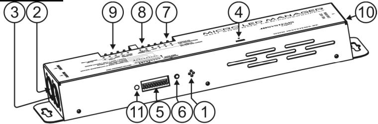
MICRO LED MANAGER
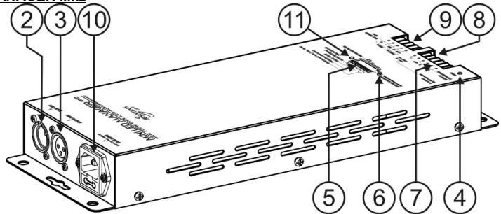
MINI LED MANAGER Mk2
- INTERNAL MICRO: used for sound activated chases.
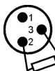
- DMX INPUT: 3pin male XLR-connector used to connect universal DMX-cables. This input receives instructions from a DMX-controller or from another Micro / Mini LED Manager when used in master/slave mode.
- DMX OUTPUT: 3pin female XLR-connector used to connect the Micro LED Manager with the next DMX appliance in the chain or with another Micro / Mini LED Manager when used in master/slave mode. The Micro / Mini LED Manager can also be used as controller for other LED projectors like for example "LED PAR56/64"
- POWER ON LED: used to check if the Micro / Mini LED Manager is connected to the mains.
- DIP SWITCHES: when used in DMX mode (DIP10 = OFF) you can set the DMX-starting address of the unit. When used in stand-alone mode (master, DIP10 = ON), you can use the DIP-switches to set different pre-programmed options.
- AUTO DMX ADDRESS BUTTON: see further to learn how to set the DMX address easily.
- OUTPUT TERMINALS: used to connect different 24Vdc common anode LED projectors. You can connect any 4pole electrical wire to connect the LED-projectors to this output. However to make life easier for you we suggest using the special CCM-50 cable (role = 50m). The wires in this cable correspond to the colors of the LEDs .
- ANALOG SWITCH INPUT: used to connect any external analog switch. This external switch can be used to switch the general output of the Micro / Mini LED Manager on/off. (external blackout) See further for more information on how to connect the analog switch.
- WALL DIMMER INPUT: used to connect our LED WALL DIMMER, a small LED controller that fits in any standard "electrical wall box". See further for more information on how to connect the LED WALL DIMMER.
- MAINS INPUT: with IEC socket, connect the supplied mains cable here.
- STATUS LED: shows the status of the unit, should blink when DMX is detected.
DIP SWITCH SETTINGS
Dip switch 10:
| Dipswitch setting | Function |
| ↓ON 12345678910 | DIP10 = OFF → DMX / Slave operation You can use the automatic DMX addressing feature or traditional DIP-switches. In the chapter DMX-addressing, we explain how DMX-addressing can be done. |
| ↓ON 12345678910 | DIP10 = ON → Master operation (stand-alone) Use the dipswitches 1~9 to set the mode, speed, patterns, fixed color color...etc functions. Below each of these functions is explained in detail. |
Dip switches 1&2: Mode (Sound/auto/fade/forced color):
| Dipswitch setting | MODE |
| ↓ON 12345678910 | SOUND: internal microphone triggers the selected patterns. |
| ↓ON 12345678910 | AUTO: the selected pattern runs automatically at the desired speed. |
| ↓ON 12345678910 | FADE: the colors of the selected pattern fade smoothly at the desired speed. |
| ↓ON 12345678910 | FIXED COLOR: use DIP-switches 6, 7, 8 & 9 to select the desired colors. |
Dip switches 3,4 & 5:Speed (from fast to slow):
| Dipswitch setting | Auto/Fade Mode | |
| ↓ON 12345678910 | Speed 1 | Fast |
| ↓ON 12345678910 | Speed 2 | |
| ↓ON 12345678910 | Speed 3 | |
| ↓ON 12345678910 | Speed 4 | |
| ↓ON 12345678910 | Speed 5 | |
| ↓ON 12345678910 | Speed 6 | |
| ↓ON 12345678910 | Speed 7 | |
| ↓ON 12345678910 | Speed 8 | Slow |
DIP switches 6,7,8 & 9: Chase & Color:
| Dipswitch setting | SOUND & AUTO MODE | FIXED COLOR MODE |
| ON 1 2 3 4 5 6 7 8 9 10 | Standard chase | White |
| ON 1 2 3 4 5 6 7 8 9 10 | Bright chase | Red |
| ON 1 2 3 4 5 6 7 8 9 10 | Mood chase | Orange |
| ON 1 2 3 4 5 6 7 8 9 10 | Spectrum random chase | Amber |
| ON 1 2 3 4 5 6 7 8 9 10 | Spectrum sequence chase | Yellow |
| ON 1 2 3 4 5 6 7 8 9 10 | Dynamic chase | Light Yellow |
| ON 1 2 3 4 5 6 7 8 9 10 | Chase Red – Cyan | Apple Green |
| ON 1 2 3 4 5 6 7 8 9 10 | Chase Green – Purple | Light Green |
| ON 1 2 3 4 5 6 7 8 9 10 | Chase Blue – Red | Green |
| ON 12345678910 | Chase Yellow – Blue | Cyan |
| ON 12345678910 | Chase Red – Green | Blue |
| ON 12345678910 | Chase Yellow – Green | Deep Blue |
| ON 12345678910 | Chase Cyan – Orange | Purple |
| ON 12345678910 | Chase Green - Light purple | Light Purple |
| ON 12345678910 | Chase Red – Yellow | Magenta |
| ON 12345678910 | Chase Gold Yellow - Blue | Pink |
ELECTRICAL INSTALLATION
The electrical installation should be carried out by qualified personal only, according to the regulations for electrical and mechanical safety in your country.
How to connect the LED-projectors to the output of the unit:
Important: Switch the Micro / Mini LED Manager OFF before you install the LED-projectors! The maximum total load of the Micro Led Manager is 50W, spread over 3 colors: each of the 3 colors has a max. load of 16W 17W! The maximum total load of the Mini Led Manager Mk2 is 100W, spread over 3 colors: each of the 3 colors has a max. load of 33W!
Two different types of passive LED projectors can be connected:
A. LED Projectors with a special 4pin connector (ex. LED STRIP):
Use the supplied conversioncable and connect theinternal 4 wires to thecorresponding 4 terminals ofthe MICRO / MINI LED
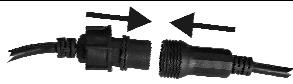
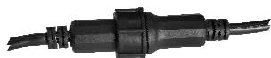
WELL CONNECTED
MANAGER. Fix all projectors properly and daisy chain the in/output cables until you reach the maximum allowed load. Make sure to fasten the plastic ring of the connector.
B. LED Projectors with open wires (ex. LED GROUND LIGHT):
Simply connect the colored wires to the corresponding terminals on the LED MICRO MANAGER. Make sure not to exceed the maximum allowed load:
- White wire: This is the common wire (anode)
- Red wire: This the power for the red LEDs.
- Green wire: This the power for the green LEDs Blue wire: This the power for the blue LEDs
Remark: the outputs to the LED-projectors are short circuits protected. However when a short circuit occurred, it must be reset: disconnect the Micro / Mini LED Manager for about 10seconds from the mains and plug it back in.
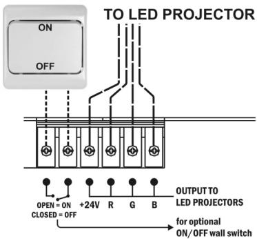
Connecting an external analog switch for blackout:
Using any ordinary on/off switch, you can put the output of the Micro / Mini LED Manager in blackout, even if it's controlled by DMX: for example you can use a regular "wall switch" to turn the LED-light on/off at any moment!
- Connected wall switch in OFF position (contacts open): output = ON
- Connected wall switch in ON position (contacts closed): output = OFF (blackout)
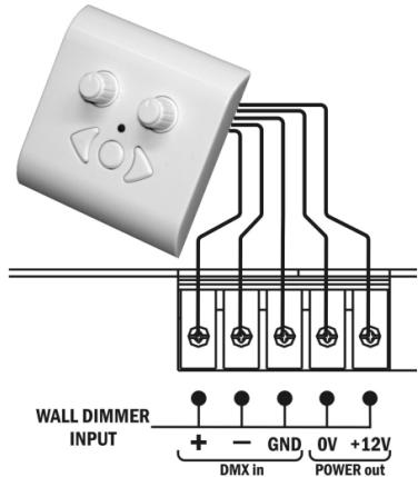
Connecting the optional LED WALL DIMMER:
The LED WALL DIMMER is a small, easy to use, controller that can be installed in any standard wall connection box. This controller can be connected directly to the Micro / Mini LED Manager. The 0V & +12V should be connected through a normal 2wire cable. The DMX-signal should be connected using a good quality balanced DMX-cable with good shielding.
Remark 1: the Micro / Mini LED Manager should be set to DMX-address 001, using the traditional DIP switches (see "DMX addressing to learn how to do this")
Remark 2: if you want to control more than 1 (Micro) LED manager, just connect the LED Managers together with the DMX in/outputs and put all DMX addresses to 001.
Electrical installation in Master/slave-mode:
- You need to "daisy chain" the DMX in/outputs of 2 or more units with a good quality balanced cable
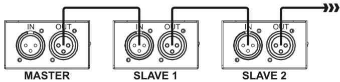
- Switch the unit with the free DMX-input connector to master, the other units are automatically switched as slaves. The DIP-switches on the slave units are disabled.
Electrical installation in Master/slave-mode with the LEDCON-02 remote:
- You need to "daisy chain" the DMX in/outputs of 1 or more units with the output of the LEDCON-02 remote using a good quality balanced cable
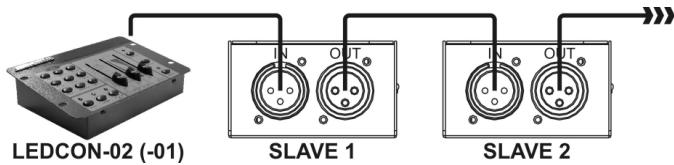
- The LEDCON-02 remote will be used to control all connected slaves. The Micro / Mini LED Managers are automatically switched as slaves. The DIP-switches on the slave units are disabled.
Electrical installation in DMX-mode:
- The DMX-protocol is a widely used high speed signal to control intelligent light equipment. You need to "daisy chain" your DMX controller and all the connected units with a good quality balanced cable
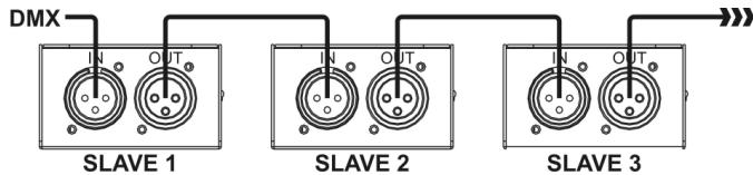
- To prevent strange behavior of the light effects, due to interferences, you must use a 90 to 120 terminator at the end of the chain. Never use Y-splitter cables, this simply won't work!
90~120 ohm resistor
- DIP-switch 10 must be set to OFF on all units. Each unit in the chain needs its proper start address so it knows which commands from the DMX-controller it has to decode. When you need a lot of power you can use several Micro / Mini LED Managers and give them the same start address. See the previous chapter to learn how to set the DMX addresses.
DMX ADDRESSED
How to set the DMX addresses:
There are 3 ways to set the DMX-address of the units. If you use setting options A or B you MUST set ALL DIP-switches to OFF position.
A. Setting individual DMX-addresses per Micro / Mini LED Manager:
- Make sure that ALL DIP-switches are set to OFF position!
- Make sure the DMX cables of all units are connected.
- Connect the first unit to a universal DMX controller.
- Connect all units to the mains so they are switched on.
- Set all DMX-channels on your DMX-controller to zero (value 000).
- Set the DMX-channel, that you want to assign as DMX-start address on your Micro / Mini LED Manager to maximum (value 255)
- Press the "Auto DMX address" button (6) on the Micro / Mini LED Manager shortly.
- If you want to set another unit to the same DMX-start address, simply press it's "Auto DMX address" button (6) and it will receive the same address.
- Done!
An example to make things clear:
We will set the DMX start address of a Micro / Mini LED Manager to 106:
- Connect the Micro / Mini LED Manager to the DMX-controller as described above and make sure all is switched on.
- Set all DMX-channels on the controller to zero (000)
- Now set DMX-channel 106 to maximum (255)
- Press the "Auto DMX address" button (6) on the Micro / Mini LED Manager shortly.
- Done! Your Micro / Mini LED Manager now has DMX address 106!
B. Automatic DMX-addressing, starting from any given start address:
To save a lot of time (imagine the time it takes to set the DIP switches of 16 units...) you can set the DMX addresses of all units in the DMX-chain just by the push of a button. No need to calculate the starting address of each individual unit, this will be done for you!
- Make sure that ALL DIP-switches are set to OFF position!
- Make sure the DMX cables of all units are connected.
- Connect the first unit to a universal DMX controller.
- Connect all units to the mains so they are switched on.
- Set all DMX-channels on your DMX-controller to zero (value 000).
- Set the DMX-channel, that you want to assign as DMX-start address on your Micro / Mini LED Manager, to maximum (value 255)
- Press the "Auto DMX address" button (6) on the first Micro / Mini LED Manager in the chain for about 5 seconds.
- Done! The first Micro / Mini LED Manager in the chain will receive the DMX-start address you chose and it will automatically calculate and program the DMX addresses of all the other units in the DMX-chain!
An example to make things clear:
We want to set the DMX-addresses of 16 units, the DMX start address of the first Micro / Mini LED Manager must be 202:
- Connect all Micro / Mini LED Manager to the DMX-controller as described above and make sure all are switched on.
- Set all DMX-channels on the controller to zero (000)
- Now set DMX-channel 202 to maximum (255)
- Press the "Auto DMX address" button (6) on the first Micro / Mini LED Manager in the chain for about 5seconds.
- Done! The first Micro / Mini LED Manager in the chain will receive DMX-start address 202 and it will automatically calculate and program the DMX addresses of all the other units in the DMX-chain! This means that the 2^nd Micro / Mini LED Manager automatically receives address 206,
the 3^rd has address 210, ..., until the 16^th Micro / Mini LED Manager who automatically receives start address 262.
You just programmed 16 Micro / Mini LED Managers, this took you about 10seconds!!!
Remark: you can mix the units with other DMX-effects that don't have the automatic DMX-addressing option. In that case you still have to set the DMX-addresses of these DMX-effects manually! You can also mix the Micro / Mini LED Managers with other JB Systems LED products that have the auto DMX-feature. They will also automatically receive their DMX-addresses.
C. Setting DMX-addresses using the DIP switches:
This is the traditional addressing method, this method should be used when used with the LED WALL DIMMER. The first 9 DIP-switches correspond to a certain DMX-value:
| DIP | #1 | #2 | #3 | #4 | #5 | #6 | #7 | #8 | #9 |
| Value | 1 | 2 | 4 | 8 | 16 | 32 | 64 | 128 | 256 |
You can combine the values of these switches to obtain any starting address between 1 and 512:
Begin address = 01 switch 1 = ON values:1
Begin address = 05 switch 1 + 3 = ON values: 1 + 4 = 5
Begin address = 09 switch 1 + 4 = ON values: 1 + 8 = 9
Begin address = 13 switch 1 + 3 + 4 = ON values: 1 + 4 + 8 = 13
Begin address = 62 switch 2 + 3 + 4 + 5 + 6 = ON values: 2 + 4 + 8 + 16 + 32 = 62
OPERATING INSTRUCTIONS
A. Standalone 1unit:
- Connect the LED projectors to the Micro / Mini LED Manager as indicated in the previous chapters.
- Switch the unit on and refer to the chapter "DIP SWITCH SETTINGS" to make yourself familiar with the various functions of the faders and buttons.
B. Two or more units in master/slave setup:
- Connect the LED projectors to the Micro / Mini LED Managers as indicated in the previous chapters.
- Connect the units with each other as explained in the chapter about electrical installations.
- Switch the Micro / Mini LED Managers on. You can only use the controls on the master unit, the controls on the slaves are disabled. Refer to the chapter "DIP SWITCH SETTINGS" to make yourself familiar with the various functions of the faders and buttons on the master unit.
C. Connect the optional LEDCON-02 for remote control:
In most cases the MICRO / MINI LED MANAGER will be installed on a wall, close to the LED-projectors. If you want to have easy access to its functions, you can connect the LEDCON-02 remote controller to the (first) Micro / Mini LED Manager. The other connections are identical to those of the standalone or master/slave setups. Don't forget to perform the automatic addressing on the LEDCON-02!!!
D. Controlled by universal DMX-controller:
- Connect the LED projectors to the Micro / Mini LED Manager(s) as indicated in the previous chapters.
- Connect the Micro / Mini LED Manager(s) with all other DMX-appliances in the DMX-chain.
- Switch all units on and set the proper DMX-addresses. (don't forget to set DIP-switch 10 to OFF)
- Switch your universal DMX-controller on and refer to the DMX chart below to control the connected Micro / Mini LED Managers:
| DMX512 Configuration | |||
| Ch1 | Ch2 | Ch3 | Ch4 |
| RED | GREEN | BLUE | DIMMER/STROBE |
| 255 100% | 255 100% | 255 100% | 248-255 OPEN 201-247 191-200 SOUND CHASE 8-190 0-7 CLOSED |
| 0 0% | 0 0% | ||
SPECIFICATIONS
Power Input: AC 100 ~ 250V (50Hz/60Hz)
Output voltage to LEDs: DC 24V common anode
Output power to LEDs:
DC 24V common anode
Micro LED Manager: 1x 50W max
Red: 16W ~ 17W max.
Green: 16W ~ 17W max.
O Blue: 16W 17W max.
Mini LED Manager Mk2: 1x 100W max
Red: 33W max.
Green: 33W max.
Blue: 33W max.
DMX connections: 3pin XLR (DMX-512 standard)
DMX channels: 4 (CH1: red, CH2: green, CH3:blue, CH4:dimmer/strobe)
Audio input: Internal microphone
Size: see drawings on the last page
Weight: 1,00kg (Micro LED Manager) 1,70kg (Mini LED Manager Mk2)
Every information is subject to change without prior notice
You can download the latest version of this user manual on our website: www.beglec.com
MODE D'EMPLOI
3-poliger XLR (DMX-512 Standard)
DMX-Kanäle:
4 (CH1: Rot, CH2: Grün, CH3: Blau, CH4: Dimmer/Strobe)
Audioeingang:
Internes Mikrofon
Abmessungen: