
FLEXSCAN T1721 - Monitor EIZO - Free user manual and instructions
Find the device manual for free FLEXSCAN T1721 EIZO in PDF.
| Product Type | Color LCD monitor with touch screen |
| Brand | EIZO |
| Model | FLEXSCAN T1721 |
| Diagonal size | 17 inches (43 cm) |
| Native resolution | 1280 × 1024 |
| Input connectors | DVI-D (digital), D-Sub mini 15-pin (analog) |
| USB port | 1 upstream port |
| Built-in speaker | Yes, with stereo mini-jack |
| Screen features | Auto EcoView, FineContrast (Custom, EyeCare, sRGB, Text), brightness adjustment |
| Touch screen | Yes (driver included on CD-ROM) |
| Ambient light sensor | Yes |
| Security lock | Kensington MicroSaver slot |
| Adjustable stand | Tilt |
| Power | 100-240 VAC, 50/60 Hz (power cord included) |
| Power consumption | Approx. 30 W (typical) |
| Weight | Approx. 4.5 kg |
| Dimensions (W × H × D) | Approx. 380 × 400 × 200 mm |
| Operating temperature | 0 °C to 35 °C |
| Included accessories | Signal cables (digital, analog, USB, audio), CD-ROM with manuals and drivers, mounting screws |
| Care | Clean with a soft, dry cloth. Do not use abrasive products. |
| Warranty | Refer to the provided limited warranty |
Frequently Asked Questions - FLEXSCAN T1721 EIZO
User questions about FLEXSCAN T1721 EIZO
0 question about this device. Answer the ones you know or ask your own.
Ask a new question about this device
Download the instructions for your Monitor in PDF format for free! Find your manual FLEXSCAN T1721 - EIZO and take your electronic device back in hand. On this page are published all the documents necessary for the use of your device. FLEXSCAN T1721 by EIZO.
USER MANUAL FLEXSCAN T1721 EIZO
Touch Panel Color LCD Monitor
Setup Manual
Important: Please read PRECAUTIONS, this Setup Manual and the User's Manual stored on the CD-ROM carefully to familiarize yourself with safe and effective usage. Please retain this manual for future reference.
Installationshandbuch
The monitor supports the following resolutions.
Touch Panel Color LCD Monitor
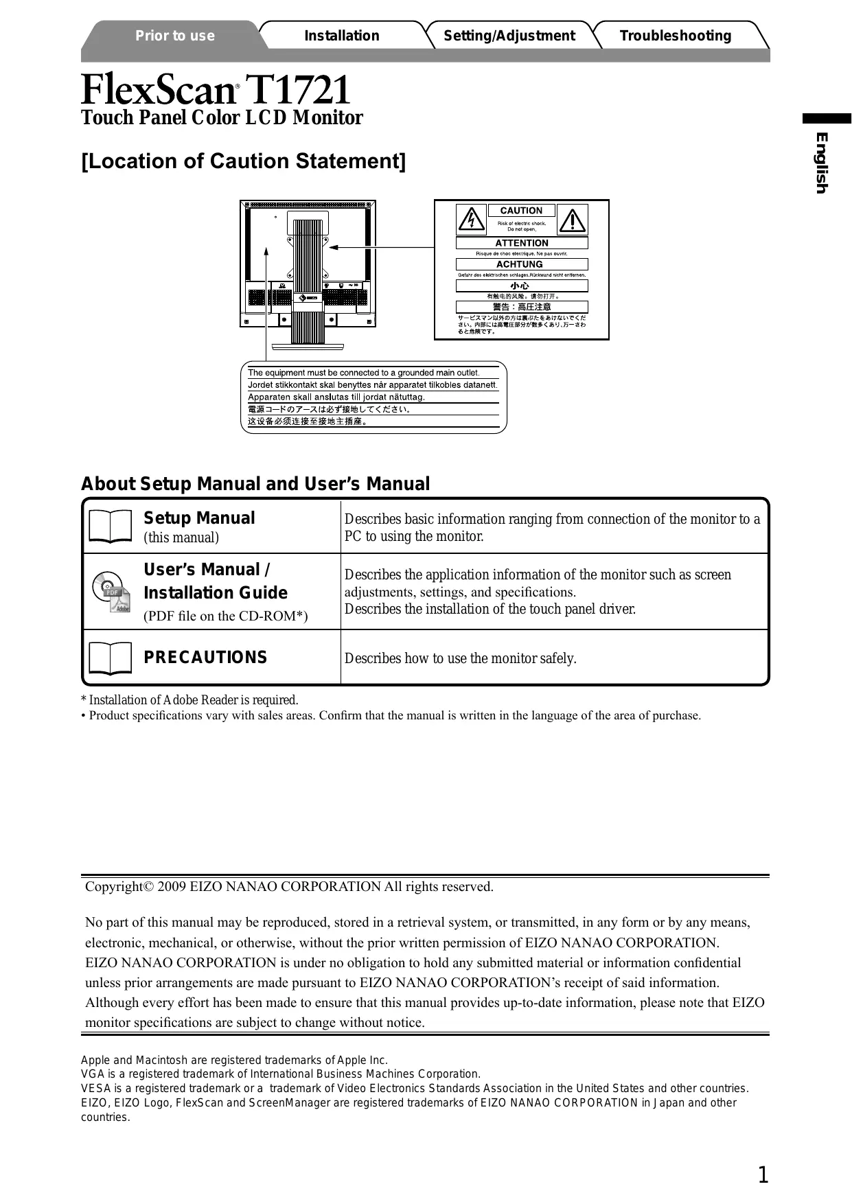
[Location of Caution Statement]
![EIZO FLEXSCAN T1721 - [Location of Caution Statement] - 1](/content/2025/01/177326/images/e04901675f86f2290221969cb99911fd987eaff991538fec414d5971805b1f5d.jpg)
About Setup Manual and User's Manual
| Setup Manual (this manual) | Describes basic information ranging from connection of the monitor to a PC to using the monitor. |
| User's Manual / Installation Guide (PDF file on the CD-ROM*) | Describes the application information of the monitor such as screen adjustments, settings, and specifications. Describes the installation of the touch panel driver. |
| PRECAUTIONS | Describes how to use the monitor safely. |
- Installation of Adobe Reader is required.
- Product specifications vary with sales areas. Confirm that the manual is written in the language of the area of purchase.
Copyright© 2009 EIZO NANAO CORPORATION All rights reserved.
No part of this manual may be reproduced, stored in a retrieval system, or transmitted, in any form or by any means, electronic, mechanical, or otherwise, without the prior written permission of EIZO NANAO CORPORATION.
EIZO NANAO CORPORATION is under no obligation to hold any submitted material or information confidential unless prior arrangements are made pursuant to EIZO NANAO CORPORATION's receipt of said information.
Although every effort has been made to ensure that this manual provides up-to-date information, please note that EIZO monitor specifications are subject to change without notice.
Package Contents
Check that all the following items are included in the packaging box. If any items are missing or damaged, contact your local dealer. NOTE
- Please keep the packaging box and materials for future movement or transport of the monitor.
- When installing the touch panel driver, please follow the installation guide on the CD-ROM.
Monitor
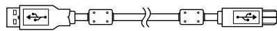
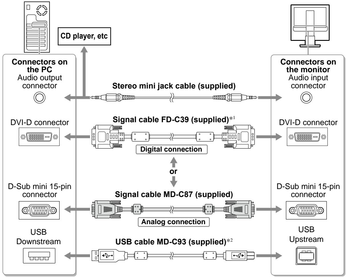
EIZO USB Cable: MD-C93
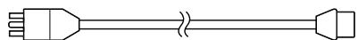
Power Cord
Digital Signal Cable: FD-C39
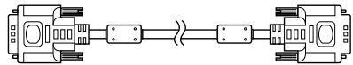
Analog Signal Cable: MD-C87
Stereo mini-jack Cable

EIZO LCD Utility Disk (CD-ROM)
- User's Manual for Monitor
- Touch Panel Driver
- Installation Guide for Touch Panel Driver
Setup Manual (this manual)
PRECAUTIONS
Limited Warranty
Recycling Information
Mounting Screws (M4 x 12, 4 pcs.)
Controls and Functions
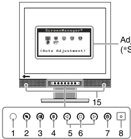
Adjustment menu (*ScreenManager®)
| 1 | Sensor | The sensor detects ambient brightness. Auto EcoView function (page 6) |
| 2 | EcoView button | Displays the setting menu of Auto EcoView and EcoView Index. |
| 3 | Volume control button | Displays the volume adjustment menu (page 5). |
| 4 | Input Signal Selection button | Switches input signals for display when two PCs are connected to the monitor. |
| 5 | Control buttons (Left, Right) | • Displays the brightness adjustment window (page 6). • Chooses an adjustment item or increases/decreases adjusted values for advanced adjustments using the Adjustment menu (page 6). |
| 6 | Enter button | Displays the Adjustment menu, determines an item on the menu screen, and saves values adjusted. |
| 7 | Power button | Turns the power on or off. |
| 8 | Power indicator | Indicates monitor's operation status. Blue: Operating Orange: Power saving Off: Power off |
| 9 | Security lock slot | Complies with Kensington's MicroSaver security system. |
| 10 | Stand | Used to adjust the angle of the monitor screen. |
| 11 | Power connector | Connects the power cord. |
| 12 | Input signal connectors | Left: DVI-D connector/Right: D-Sub mini 15-pin connector. |
| 13 | USB port (Up) | Connects the PC to the monitor with a USB cable. |
| 14 | Stereo mini jack | Connects the stereo mini jack cable. |
| 15 | Speaker | Outputs audio source. |
* ScreenManager 器 is an EIZO's nickname of the Adjustment menu. (For how to use SreenManagcr, refer to the User's Manual on the CD-ROM.)
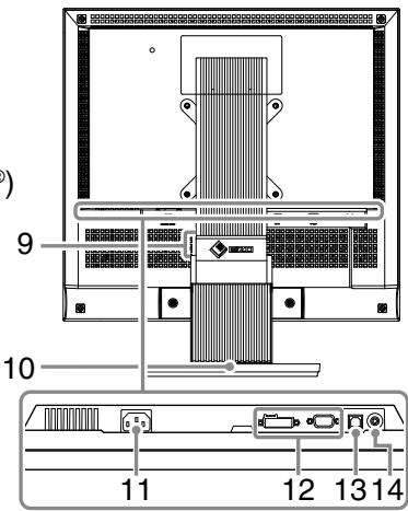
Connecting Cables
Attention
NOTE
- When replacing the current monitor with a T1721 monitor, be sure to change the PC settings for resolution and vertical frequency to those which are available for the T1721 monitor referring to the resolution table (back of cover page) before connecting the PC.
- When connecting two PCs to the monitor, refer to the User's Manual on the CD-ROM.
1 Check that the monitor and the PC are powered off.
2 Connect the monitor to the PC with a signal cable that matches the connectors. After connecting the cable connectors, tighten the screws of the connectors to secure the coupling.
1 Do not use the Dual Link cable.
2 Required when used as a touch panel.
3 Plug the power cord into a power outlet and the Power connector on the monitor.
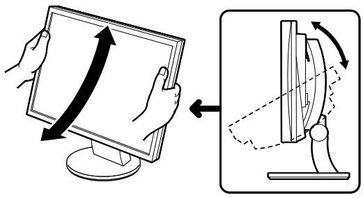
Adjusting the Screen Angle
Hold left and right edge of the monitor with both hands, tilt the screen to the best condition for working.
Attention
- Be sure that the cables are correctly connected.
Displaying the Screen
1 Press to turn on the monitor.
The monitor's power indicator lights up blue.
2 Turn on the PC.
The screen image appears.
When turning on the monitor and PC for the first time with the analog signal, the Auto Adjustment function works to adjust the clock, phase, and display position automatically.
Installing the Touch Panel Driver
Attention
- The user account to be used for installing the touch panel driver must have the "Administrators" privilege.
- When reinstalling the touch panel driver to update the driver, etc., restart the PC after uninstalling the driver and then install it.
1 Uninstall the other touch panel driver, if it is installed.
2 Install the touch panel driver according to the instructions included in the EIZO LCD Utility Disk (CD-ROM).
For details, refer to the Installation Guide for Touch Panel Driver on the CD-ROM.
Attention
- Turn off the monitor and PC after using them. Unplugging the power cord completely shuts off power supply to the monitor. Touch operation is effective until turning off both PC and monitor.
Calibrating the Monitor
Calibrate the monitor according to the Installation Guide for Touch Panel Driver on the CD-ROM.
Adjusting Speaker Volume
1 Press
The speaker volume adjustment screen appears.
2 Adjust the speaker volume with or .
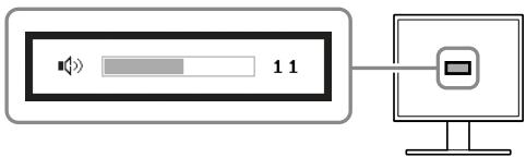
Speaker volume adjustment screen
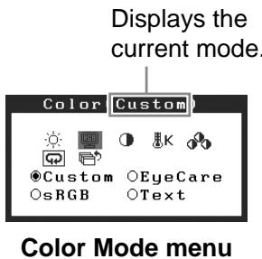
Selecting Display Mode
FineContrast allows you to select the best display mode easily according to monitor's application. For details of FineContrast, refer to the User's Manual on the CD-ROM.
FineContrast Mode
| Custom | Available for making desired setting. |
| EyeCare | Allows the brightness to be set lower than possible with other modes. |
| sRGB | Suitable for color matching with sRGB compatible peripherals. |
| Text | Suitable for displaying texts for word processing or spreadsheets. |
1 Press .
2 Choose
3 Choose
The
4 Select the mode with or , and press .
The selected mode is set.
Adjusting Brightness
1 Press or l
The brightness adjustment screen appears.
2 Adjust the brightness with or .
Press to increase screen brightness or press to decrease.
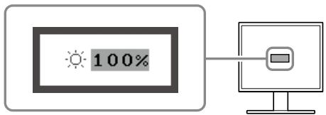
Brightness adjustment window
NOTE
- The sensor on the front side of the monitor detects the environmental brightness to adjust the screen brightness automatically and comfortably with the Auto EcoView function. For details, refer to the User's Manual on the CD-ROM.
Performing Advanced Settings/Adjustments
Advanced adjustments for the color and various settings are available using the Adjustment menu.
For details of each adjustment function, refer to the User's Manual on the CD-ROM.
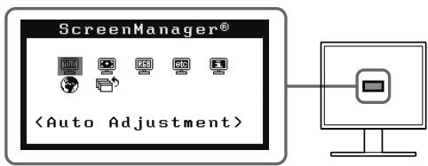
Adjustment menu
The basic settings and adjustments are completed. For advanced settings/adjustments, refer to the User's Manual on the CD-ROM.
If no picture is displayed on the monitor even after the following remedial action is taken, contact your local dealer.
1. Check the Power indicator.
| Symptom | Status | Possible cause and remedy |
| No picture | Power indicator does not light. | Check whether the power cord is connected correctly. |
| Press Ⓞ . | ||
| Power indicator is lighting blue. | Set each adjusting value in <Brightness>, <Contrast> and <Gain>* to higher level. | |
| Power indicator is lighting orange. | Switch the input signal with Ⓐ . | |
| Operate the mouse or keyboard. | ||
| Touch the panel surface. | ||
| Turn on the PC. |
- For the setting of the brightness, contrast and gain, please refer to the User's Manual on the CD-ROM.
2. Check the error message that remains on the screen.
These messages appear when the input signal is incorrect even if the monitor is functioning.
| Symptom | Status | Possible cause and remedy |
| Signal Check Analog No Signal | The input signal is not received. | The message shown left may appear, because some PCs do not output the signal soon after power-on. |
| Check whether the PC is turned on. | ||
| Check whether the signal cable is connected properly. | ||
| Switch the input signal with S. | ||
| Signal Error Digital fD: 94.6MHz fH: 68.7kHz fU: 85.0Hz | The signal frequency is outside the specification. Incorrect signal frequency is shown in red. | Select an appropriate display mode using the graphics board's utility software. Refer to the manual of the graphics board for details. fD: Dot Clock (Displayed only when the digital signal inputs) fH: Horizontal Frequency fV: Vertical Frequency |
FlexScan T1721
- Setup Manual
- Installationshandbuch
- [Location of Caution Statement]
- About Setup Manual and User's Manual
- Package Contents
- Controls and Functions
- Connecting Cables
- Attention
- NOTE
- Adjusting the Screen Angle
- Displaying the Screen
- Installing the Touch Panel Driver
- Calibrating the Monitor
- Adjusting Speaker Volume
- Selecting Display Mode
- Adjusting Brightness
- Press or l array
- Adjust the brightness with or .
- Performing Advanced Settings/Adjustments
- Check the Power indicator.
- Check the error message that remains on the screen.
- FlexScan T1721
Brand : EIZO
Model : FLEXSCAN T1721
Category : Monitor