
PSU 4000 - Power Supplies for Audio Equipment AKG - Free user manual and instructions
Find the device manual for free PSU 4000 AKG in PDF.

| Product type | Power supply for audio equipment |
| Brand | AKG |
| Model | PSU 4000 |
| Dimensions (L × W × H) | 200 × 190 × 44 mm |
| Weight | 1.3 kg |
| Input power | 90 to 264 V AC, 47-63 Hz |
| Output voltage | 3 outputs of 12 V DC |
| Maximum output current | DC OUT 1: 2.5 A, DC OUT 2-3: 2 A |
| Number of outputs | 3 |
| Fuse | 2 A inert (standard IEC type) |
| Mains plug type | IEC (C14) |
| Rack-mountable format | 19" 1U |
| Compatibility | WMS 4000 systems and associated components |
| Main functions | Centralized power supply, short-circuit, overload and overheating protection, status LED per output |
| Maintenance and cleaning | Unplug from mains, clean with a slightly damp cloth, no solvents or abrasives |
| Safety | Do not open, repair by authorized personnel only, use on outlet with protective earth |
| Spare parts and repairability | Fuse replaceable by user; for any other repairs, contact AKG support |
| Operating temperature | Not specified, avoid heat sources |
| Included accessories | Mains cable, DC connection cables (quantity not specified) |
Frequently Asked Questions - PSU 4000 AKG
User questions about PSU 4000 AKG
0 question about this device. Answer the ones you know or ask your own.
Ask a new question about this device
Download the instructions for your Power Supplies for Audio Equipment in PDF format for free! Find your manual PSU 4000 - AKG and take your electronic device back in hand. On this page are published all the documents necessary for the use of your device. PSU 4000 by AKG.
USER MANUAL PSU 4000 AKG
Please read the manual before using the equipment!
MODE D'EMPLOI p.9
- Do not spill any liquids on the equipment and do not drop any objects through the ventilation slots in the equipment.
- The equipment may be used in dry rooms only.
- The equipment may be opened, serviced, and repaired by authorized personnel only. the equipment contains no user-serviceable parts.
- Before connecting the equipment to power, check that the AC mains voltage stated on the equipment is identical to the AC mains voltage available where you will use the equipment.
- To avoid the risk of electric shock, make sure to connect the equipment to a grounded power outlet. It is illegal to disconnect the protective ground wire or use a non-standard power plug.
- Prior to connecting receivers to the equipment, compare the output voltage of the equipment with the operating voltages of all receivers. Only connect receivers operating on the same voltage, type of current (AC or DC), and having the same connector polarity as the outputs on the PSU 4000.
- The current drain on the DC OUT 1 output of the equipment must never exceed 2.5A , the current drain on outputs DC OUT 2 and DC OUT 3 must never exceed 2A .
- Never short any of the equipment's outputs!
- Never apply any voltage to any of the equipment's outputs. Never connect any type of power supply to a PSU 4000 output. This may cause damage to both the equipment and the power supply.
10.If any solid object or liquid penetrates into the equipment, shut down the sound system immediately. Disconnect the power cable from the power outlet immediately and have the equipment checked by AKG service personnel.
11.If you will not use the equipment for a long period of time, disconnect the power cable from the power outlet. Please note that the equipment will not be fully isolated from power when you set the on/off switch to OFF. - Do not place the equipment near heat sources such as radiators, heating ducts, or amplifiers, etc. and do not expose it to direct sunlight, excessive dust, moisture, rain, mechanical vibrations, or shock.
- To avoid hum or interference, route all cables away from high-voltage lines of any type.
- Clean the equipment with a moistened (not wet) cloth only. Be sure to disconnect the power cable from the power outlet before cleaning the equipment! Never use caustic or scouring cleaners or cleaning agents containing alcohol or solvents since these may damage the enamel and plastic parts.
15.When routing cables, make sure that nobody can trip over them
16.Do not use any accessories except those recommended by AKG. - Do not use the equipment for any applications other than those described in this manual. AKG cannot accept any liability for damages resulting from improper handling or misuse.
1.2 Environment

- When scrapping the equipment, separate the case, circuit boards, and cables, and dispose of all components in accordance with local waste disposal rules.
- The packaging of the equipment is recyclable. To dispose of the packaging, make sure to use a collection/recycling system provided for that purpose and observe local legislation relating to waste disposal and recycling.

2 Description
2.1 Introduction
*Refer to figs. 3 and 4. See SR 4000 manual for details.
Thank you for purchasing an AKG product. This Manual contains important instructions for setting up and operating your equipment. Please take a few minutes to read the instructions below carefully before operating the equipment. Please keep the Manual for future reference. Have fun and impress your audience!
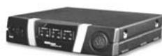
The PSU 4000 is a power supply with three 12 V DC outputs for powering a WMS 4000 multichannel system. The unit features a 1-U 19'' case for rack mounting*.
The PSU 4000 replaces the AC adapters that come with the various WMS 4000 components and thus greatly simplifies the setting up of multichannel wireless systems.
2.2 Unpacking
1 PSU 4000
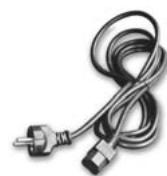
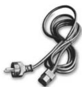
1 IEC power cable
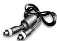
3 connecting cables with DC connectors
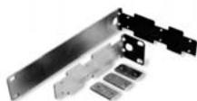
1 19" rack mount kit
Check that the packaging contains all of the components listed above. Should anything be missing, please contact your AKG dealer.
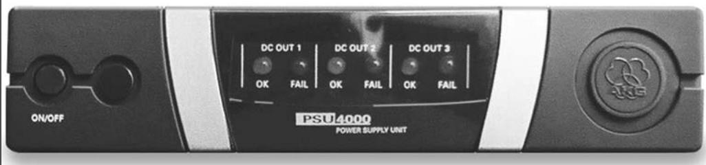
The power supply front panel provides the following controls and indicators:
ON/OFF: Press this key to switch power to the unit ON. Press again to switch power to the unit OFF.
DC OUT 1 - 3: The blue OK LED will be lit for as long as the assigned DC output DC OUT 1, 2, or 3 provides the correct supply voltage for active components. Should the supply voltage at a DC output be shorted or fail (drop below 2V ), the output be overloaded, or the temperature of the unit exceed the acceptable level, the OK LED for that input will extinguish and the red FAIL LED be lit instead.
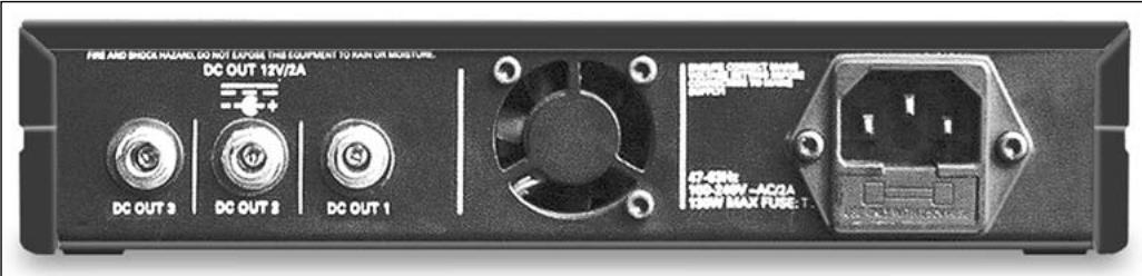
The PSU 4000 rear panel provides the following inputs and outputs:
IEC receptacle accepting the matching connector on the supplied power cable. The IEC receptacle incorporates a standard fuse holder with a 2 A slow-blow fuse. The PSU 4000 uses a wide-range power transformer for primary voltages from 90 VAC to 264 VAC.
DC OUT 1: DC output jack with a load capacity of up to 2.5 A for connecting a PS 4000 with an antenna system and up to four SR 4000 receivers (the receivers are powered via the antenna cables) or one other WMS 4000 component (HUB 4000, HPA 4000, CU 4000).
DC OUT 2, DC OUT 3: DC output jacks with a load capacity of up to 2 A for connecting a WMS 4000 component (SR 4000, HUB 4000, HPA 4000, CU 4000, PS 4000 with no antenna system).

Fig. 1: Front panel controls and indicator LEDs.
Make sure the total current consumption of all components connected to DC OUT 1 does not exceed 2.5 A and the total current consumption of all components connected to DC OUT 2 or DC OUT 3 does not exceed 2 A. Higher loads can cause damage to the PSU 4000 due to overheating.
2.3 Controls
2.3.1 Front Panel
Refer to fig. 1.
2.3.2 Rear Panel
Refer to fig. 2.
Refer to fig. 5.
Refer to fig. 5.
Important!
3 Setting Up
Fig. 2: Rear panel inputs and outputs.

Do not connect the unit to power before you have made all audio and DC connections.

Check that the output voltage of the PSU 4000 is identical to the operating voltage of the components your about to connect. Operating components on an incorrect voltage may damage both the components and the PSU 4000.
- Use the supplied connecting cables to connect the DC OUT jacks on the rear panel of the PSU 4000 to the DC input jacks on the desired components.
- Each connecting cable has a ferrite core attached near one end. Make sure to connect this end of each cable to the PSU 4000.

Never plug a connecting cable into an unused DC OUT jack. The unused DC connector on the cable may be shorted by metal parts.
The PSU 4000 features a wide-range power transformer for primary voltages from 90 VAC to 264 VAC. Therefore, you can connect the unit to any power outlet with an AC voltage within this range and a frequency between 47Hz and 63Hz .
- Use the supplied power cable to connect the PSU 4000 to a convenient power outlet.

To avoid the risk of electric shock, make sure to connect the equipment to a grounded power outlet.
Important!
Important!
3.1 DC Connections
Connect PS 4000 with antenna system to DC OUT 1 only!
Important!
3.2 Connecting to Power
Warning!
3.3 Powering Up and Powering Down
- To power up, press the ON/OFF key.
The three DC OUT OK LEDs will be lit.
The power LEDs (if any) on the components connected to the PSU 4000 will light if the components are on.
For details on operating WMS 4000 components, refer to the appropriate manuals.
- To power down, press ON/OFF again.
3.4 Fuse Warning!

Make sure to replace the fuse integrated in the IEC receptacle with a fuse of the same type (2 A slow-blow only. Other types of fuses may cause malfunctioning or a risk of fire.

4 Cleaning
Important!
- Disconnect the AC adapter from the power outlet.
- Use a cloth moistened (not wet!) with water to clean the surfaces of the equipment.

Never use caustic or scouring cleaners or cleaning agents containing alcohol or solvents since these may damage the enamel or plastic parts.

5 Troubleshooting
| Problem | Possible Cause | Remedy |
| None of the front panel LEDs is lit. | 1. PSU 4000 is not connected to power. 2. PSU 4000 is OFF. 3. Fuse on the distribution fuse board is blown. 4. Fuse on PSU 4000 is blown. 5. PSU 4000 is defective. | 1. Connect PSU 4000 to power. 2. Switch PSU 4000 ON. 3. Check fuse. 4. Replace fuse with fuse of same type (2 A slow-blow). 5. Disconnect all connecting cables from DC OUT jacks. If LEDs fail to illuminate, contact your nearest AKG Service Center. |
| Connected component(s) fail(s) to function although associated OK LED(s) is (are) lit. | 1. Connected component(s) is (are) off. 2. DC connector on connecting cable is not plugged all the way in. 3. Connecting cable is defective. 4. Incorrect voltage (component defective). 5. Incorrect polarity (component defective). | 1. Switch component(s) on. 2. Disconnect connecting cable and plug connector all the way into DC OUT jack. 3. Replace connecting cable. 4. Contact your nearest AKG Service Center. 5. Contact your nearest AKG Service Center. |
| One of the FAIL LEDs is lit. | 1. DC output is shorted. 2. DC output is overloaded. 3. Unit is overheated. 4. Connecting cable or connected component is defective. 5. Internal error. | 1. Eliminate the short. 2. Check connected load: Total current consumption of all connected components msut not exceed 2.5 A (DC OUT 1) or 2 A (DC OUT 2-3). 3. Check ventilator, check connected load, place unit in a cooler location. 4. Disconnect cable. If OK LED illuminated, replace connecting cable or have component checked by AKG Service. 5. Contact your nearest AKG Service Center. |

6 Specifications
6.1 Input
Input voltage
90 VAC to 264 VAC
Frequency
47 to 63 Hz
6.2 Outputs
Output voltage
3 outputs, 12 VDC each
6.3 System
Weight:
1.3 kg (3.2 lbs.)
Size
200 × 190 × 44 ~mm (7.8 x 7.5 x 1.7 in.)
6.4 Standards
This product conforms to the standards listed in the Declaration of Conformity. To order a free copy of the Declaration of Conformity, visit http://www.akg.com or contact sales@akg.com.
1 cabo de forca com conductor IEC
5 Resolver problemas
For other products and distributors worldwide visit www.akg.com


ROHS OK
H A Harman International Company
Technische Änderungen vorbehalten. Specifications subject to change without notice. Ces caractéristiques sont susceptibles de modifications. Ci riserviamo il diritto di effettuare modifiche tecniche. Nos reservamos el correcho de introducir modificaciones sociales. Especificações sujeitas a mudanças sem aviso prévio.
Printed in Hungary.
12/09/9100 U 10600

Brand : AKG
Model : PSU 4000
Category : Power Supplies for Audio Equipment