PT 300 - Wireless Microphone AKG - Free user manual and instructions
Find the device manual for free PT 300 AKG in PDF.

| Product type | Pocket transmitter (bodypack) for wireless HF microphone system |
| Brand | AKG |
| Model | PT 300 (part of WMS 300 system) |
| Frequency range | UHF from 798 to 955 MHz (16 frequencies on 20 MHz band) |
| Modulation | FM with RMS compander |
| RF output power | 6 mW |
| Antenna | Integrated 1/4 λ flexible antenna |
| Audio bandwidth | 70 Hz - 20 kHz |
| Harmonic distortion | < 0.8% at nominal excursion |
| Signal-to-noise ratio | > 100 dB |
| Input sensitivity | Switchable to 4 values: 27, 100, 330, 1080 mV |
| Input impedance | MIC: 30 kΩ with 7 V phantom power; LINE: 60 kΩ |
| Audio input | Lockable 3.5 mm jack (optional Lemo/Fischer) |
| Power supply | 3 AA 1.5 V batteries (LR61) or NiCd/NiMH rechargeable batteries |
| Battery life | Approx. 12 h with alkaline batteries; > 4.5 h with NiCd 700 mAh; > 6 h with NiMH 1100 mAh |
| Power consumption | < 150 mA |
| Dimensions | 69 x 18 x 94 mm (L x W x H) |
| Net weight | Approx. 230 g (without batteries) |
| Main features | MIC/MUTE/LINE switching, 4-position sensitivity adjustment, 16-channel carrier selector, peak and battery status LED indicator |
| Maintenance and cleaning | Clean metal surfaces with a soft cloth moistened with alcohol. The windscreen can be washed with soapy water and air-dried. |
| Safety | Avoid contact with liquids, drops, shocks, extreme temperatures, dust, and moisture. Do not expose to sunlight. |
| Spare parts and repairability | Replacement parts: AA batteries, foam windscreen W 3001, belt clip. For repair, contact AKG service. |
| General information | Compliant with ETS 300 445 and ETS 300 422 standards. Used with SR 300 receiver for true diversity reception. |
Frequently Asked Questions - PT 300 AKG
User questions about PT 300 AKG
0 question about this device. Answer the ones you know or ask your own.
Ask a new question about this device
Download the instructions for your Wireless Microphone in PDF format for free! Find your manual PT 300 - AKG and take your electronic device back in hand. On this page are published all the documents necessary for the use of your device. PT 300 by AKG.
USER MANUAL PT 300 AKG
AKG ACOUSTICS, U.S. 1439 Donderson Pike, Airpark Business Centre 12, 500 Park Avenue, St. Louis, MO 63277
Tel: (815) 360-0499; Fax: (815) 360-2217
Scheddler Japan Ltd. 2-4-3, Utesan, Shinkyo-ku, Tokyo 151-0964/JAPAN 3-4-3, Utesan, Shinkyo-ku, Tokyo 151-0462/2113
Erikson Pro Audio 650 McCallty, St. Laurent, Quebec, H4T 1N1, Canada Tel: (814) 738-3000; Fax: (814) 737-7099
Shimura, Saitama, Japan
INHALT
- SR 300 Stationary True Diversity Receiver 12
6.1.Standard Accessories 12
6.2. Optional Accessories 12
6.3. Controls 12
6.4. Squelch 12
6.5. True Diversity Reception 12
- Carrier Frequencies 13
7.1. Sets of Carrier Frequencies 13
7.2. Ordering Transmitters and Receivers 13
7.3. Selecting Carrier Frequencies on the HT 300 Handheld Transmitter 13
7.4. Selecting Carrier Frequencies on the PT 300 Bodypack Transmitter 13
7.5. Selecting Carrier Frequencies on the SR 300 Receiver 13
- Setting Up 13
HT 300 Handheld Transmitter 13
8.1. Inserting/Replacing and Testing Batteries 13 PT 300 Bodypack Transmitter 13
8.2. Inserting/Replacing and Testing Batteries 13 SR 300 True Diversity Receiver 14
8.3. Connecting to Power and Setting Up 14
8.4. Adjusting Sensitivity on HT 300 and PT 300 Transmitters 14
8.5. Battery Life 15
-
Antenna Placement 15
10.Before the Soundcheck 15 -
How to Minimize Feedback 15
- Cleaning 15
- Specifications 16
13.1. HT 300 and PT 300 Transmitters 16
13.2. SR 300 Receiver 17
1. Introduction
Thank you for selecting the WMS 300 wireless microphone system from AKG. To make the best use of your WMS 300, please read this manual thoroughly before operating the equipment. Good luck and have fun!
2. Precautions
- Spill no liquids on the equipment and do not drop any objects through any openings in the equipment.
- Do not place the equipment near heat sources such as radiators, air ducts, or amplifiers and do not expose it to direct sunlight, excessive dust, moisture, rain, mechanical vibrations, or shock.
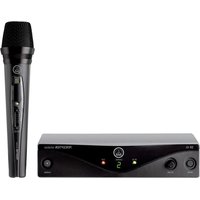
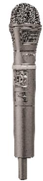
3. HT 300 Handheld Transmitter
The HT 300 handheld transmitter specifically designed for the WMS 300 wireless microphone system can be combined with three interchangeable microphone elements, the D 3700 WL, D 3800 WL, and C 5900 WL. The HT 300 transmitter operates in the high-band UHF range between 770 MHz and 950 MHz and lets you select one of 16 carrier frequencies. The transmitting antenna is protected from damage by an impact resistant plastic cover. The controls are easy to locate and recessed in the case in order to prevent accidental actuation.
The HT 300 is exceptionally rugged to survive tough handling on stage.
3.1.Standard Accessories
3 AA size 1.5-V batteries
1 screwdriver
SA 43 stand adapter
3.2. Optional Accessories
W 3001 foam windscreen
3.3. Controls
Refer to fig.1:
1 - Pin strip
2 - Locking collar
3 - Peak/battery status LED
4 - Power LED
5 - SENS. sensitivity control
6 - MIC O/I microphone on/off switch
7 - POWER O/I power on/off switch
8 - Screw-on battery compartment lid
9 - Carrier frequency selector
10 - Carrier frequency table
11 - Frequency set designation label
12 - Battery ejector
4. D 3700 WL, D 3800 WL, C 5900 WL Interchangeable Microphone Elements
The D 3700 WL, D 3800 WL, and C 5900 WL interchangeable microphone elements use the same transducer capsules and protective baskets as the cabled D 3700, D 3800, and C 5900 microphones of the legendary Tri-Power Series and provide a number of benefits:
- Frequency independent hypercardioid polar pattern for high gain before feedback.
Transducer shock mount and MMS Moving Magnet System for optimum handling noise rejection. - Integrated protective baskets for ultimate protection of the capsule from damage.
Integrated wind and pop screen.
4.1. Controls
Refer to fig. 1:
13 - Detachable wire-mesh grill
14 - Contact strip
4.2. Mounting the D 3700 WL, D 3800 WL, or C 5900 WL Microphone Element
- Plug the microphone element on the HT 300 handheld transmitter making sure to align the pin strip (1) with the contact strip (14).
- Rotate the blue locking collar (2) CCW (against the direction of the arrow) until the microphone element is firmly held in place.
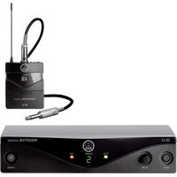
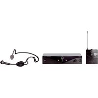
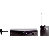
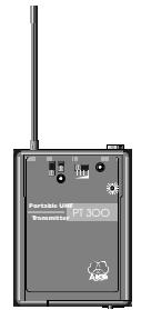
5. PT 300 Bodypack Transmitter
The PT 300 bodypack transmitter has been specifically designed for the WMS 300 wireless microphone system. The PT 300 operates within a cannel bandwidth of up to 20MHz in the high-band UHF range from 770MHz to 950MHz and lets you select one of 16 carrier frequencies within the channel bandwidth.
The audio input on a lockable mini jack accepts dynamic microphones as well as condenser microphones for 5-V power supply. You may also connect an electric guitar, electric bass, or portable keyboard.
Note:
The PT 300 is also available on request with a Lemo or Fischer audio input socket.
5.1.Standard Accessories
Belt clip
3 AA size 1.5-V batteries
1 screwdriver
5.2. Controls
Refer to fig. 2:
15 - Antenna
16 - MIC/MUTE/LINE switch for microphone power supply and mute function
17 - POWER 0/1 power on/off switch
18 - Power LED
19 - SENSITIVITY control
20 - Peak/battery status LED
21 - MIC audio input
22 - CH. carrier frequency selector
23-Belt clip
24 - Carrier frequency table
25 - Frequency set designation
26 - Battery compartment door
5.3. Connecting and Disconnecting a Microphone or Instrument
5.3.1. Lockable Mini Jack
To connect a microphone with threaded mini jack plug, plug the microphone connector into the MIC jack (21) and screw the connector CW all the way in. The connector will not make electrical contact before it is screwed all the way in.
Condenser microphones require a power supply. To switch on the microphone power supply integrated in the PT 300, set the MIC/MUTE/LINE switch (16) to MIC.
When connecting a dynamic microphone or instrument cable, set the MIC/MUTE/LINE switch (16) to LINE to switch the condenser microphone power supply off.
To mute the audio input, set the MIC/MUTE/LINE switch (16) to MUTE.
To disconnect the microphone or instrument cable, unscrew the mini jack plug on the microphone or instrument cable and unplug it from the MIC jack (21).
5.3.2. Lockable Lemo or Fischer Socket (Special version)
To connect a microphone with a lockable Lemo or Fischer plug, insert the cable connector into the MIC jack (21) to the point that a click indicates it is securely held in place. (It should not be possible to unplug the connector by pulling at the cable.)
Condenser microphones require a power supply. To switch on the microphone power supply integrated in the PT 300, set the MIC/MUTE/LINE switch (16) to MIC.
When connecting a dynamic microphone or instrument cable, set the MIC/MUTE/LINE switch (16) to LINE to switch the condenser microphone power supply off.
To mute the audio input, set the MIC/MUTE/LINE switch (16) to MUTE.
To disconnect the microphone, pull the end of the bushing away from the case. This unlocks the connector and allows you to unplug it.
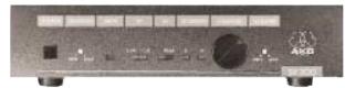
6. SR 300 Stationary True Diversity Receiver
The SR 300 is a stationary diversity receiver for use with all WMS 300 transmitters. The SR 300 operates within a cannel bandwidth of up to 20MHz in the high-band UHF range from 770MHz to 950MHz and lets you select one of 16 carrier frequencies within the channel bandwidth.
6.1.Standard Accessories
11.7-V AC remote power supply
2 RA 300 UHF antennas
6.2. Optional Accessories
RA 300 B: Antenna with integrated booster
PS 300: UHF antenna splitter with 2 × 8 antenna outputs for SR 300 receivers
MK PS: Antenna splitter connecting cable
MK A10: 10-m (33-ft.) antenna cable
RMU 2: 19'' rack mount mainframe for 2 SR 300s
RMU 2A: 19" rack mount mainframe for 2 SR 300s with front panel antenna sockets, antenna splitter, and fixed connecting cables
BP1: Blank panel
CH 1: Carrying case
6.3. Controls
Refer to fig. 3:
27 - POWER on/off switch
28 - SQUELCH threshold control
29 - MUTE LED
30 - RF field strength meter
31 - AF audio level meter
32 - DIVERSITY LEDs A and B
33 - CHANNEL carrier frequency selector
34 - VOLUME output level control
35 - Frequency set designation
36 - Antenna socket
37 - Balanced audio output
38 - Unbalanced audio ouptut
39 - Power input
40 - Strain relief
41 - Carrier frequency table
6.4. Squelch
Each SR 300 receiver incorporates a squelch circuit that switches the receiver off when the received signal is too weak, in order to suppress the related noise or the residual noise of the receiver while the transmitter is off. The SQUELCH control (28) adjusts the squelch threshold from -95 dBm (MIN) to -80 dBm (MAX). The MUTE LED (29) lights to indicate the audio output is muted.
It is good practice to keep the SQUEELCH control (29) at MIN in order to utilize the full reception sensitivity of the receiver.
6.5. True Diversity Reception
Reflections of metal parts, walls, ceiling, etc. may weaken the transmitter signal to the point that the squelch will switch the receiver off. This can be largely prevented by a technique called true diversity reception. It uses two antennas each connected to its own receiver circuit. A weighting circuit noiselessly switches the signal with the better S/N ratio to the output. The SR 300 receiver contains both the two independent RF sections and the weighting circuit. The A and B LEDs (32) illuminate to indicate which RF section is routed to the audio outputs (37), (38) at any time.
7. Carrier Frequencies
The HT 300 handheld transmitter, PT 300 bodypack transmitter, and SR 300 receiver have been factory programmed for a maximum of 16 carrier frequencies. The carrier frequency selectors on the HT 300 (9), PT 300 (22), and SR 300 (33) each allow you to select one of these frequencies. The carrier frequency tables on the transmitters (10), (24) and receiver (41) list all the frequencies your WMS 300 can be tuned to.
If, due to government regulations, your system provides less than 16 frequencies then the remaining storage locations all contain the highest of the preset frequencies.
7.1. Sets of Carrier Frequencies
Each set of carrier frequencies has a specific designation (11), (25), (35). Be sure to use only transmitters and receivers tuned to the same set of carrier frequencies. Otherwise it may be impossible to tune transmitters and receivers to the same carrier frequency.
7.2. Ordering Transmitters and Receivers
If you want to order additional transmitters or receivers operating on the same set of frequencies as your original equipment, be sure to state the designation of your original frequency set (11), (25), (35) and the serial number of the original device. We need this information to ensure your new equipment will be compatible with the original units.
7.3. Selecting Carrier Frequencies on the HT 300 Handheld Transmitter
- If the transmitter is switched on, switch it off by setting the POWER 0/1 switch (7) to 0.
- Unscrew the battery compartment lid (8) CCW.
-
Set the frequency selector (9) to the desired frequency (called a "Channel" in the carrier frequency table). Refer to the table on the right to set each DIP switch to the required position. (The same table is also printed on a sticker (10) next to the frequency selector (9).)
-
Switch the transmitter back on by setting the POWER 0/1 switch to I.
- Screw the battery compartment lid (8) back on CW.
(Tabelle:) Schalter = Switch Kanal = Channel
Important:
Be sure to switch the transmitter off prior to selecting a different carrier frequency and back on afterwards. Otherwise, the new carrier frequency will not be stored.
7.4. Selecting Carrier Frequencies on the PT 300 Bodypack Transmitter
- If the transmitter is switched on, switch it off by setting the POWER 0/1 switch (17) to 0.
- Set the frequency selector (22) to the desired frequency (called a „Channel" in the carrier frequency table).
Refer to the table on the right to set each DIP switch to the required position. (The same table is also printed on a sticker (24) next to the frequency selector (22).)
- Switch the transmitter back on by setting the POWER 0/1 switch to I.
Important:
Be sure to switch the transmitter off prior to selecting a different carrier frequency and back on afterwards. Otherwise, the new carrier frequency will not be stored.
Note:
Check that the transmitter and receiver are tuned to the same set of carrier frequencies (labels (11), (25), (35)) and set to the same carrier frequency.
7.5. Selecting Carrier Frequencies on the SR 300 Receiver
Set the CHANNEL control (33) to the desired carrier frequency (channel 1 to 16). The opening in the control knob indicates the selected carrier frequency.
8. Setting Up
| HT 300 Handheld Transmitter | PT 300 Bodypack Transmitter |
| Mount the microphone element on the HT 300 handheld transmitt er referring to section 4.2. „Mounting the Microphone Element (D 3700 WL, D 3800 WL, C 5900 WL)". | Connect the microphone or instrument referring to section 5.3. „Connecting and Disconnecting a Microphone or Instrument". |
| 8.1. Inserting/Replacing and Testing Batteries Refer to fig. 4. | 8.2. Inserting/Replacing and Testing Batteries Refer to fig. 5. |
| 1. Unscrew the battery compartment lid (8) CCW. | 1. Unlock the battery compartment door (26) by turning the locking screw CCW through 90 degrees using a coin. |
| 2. Insert the supplied batteries into the battery compartment, observing the polarity marks (+/-). | 2. Slide the battery compartment door (26) outward in the direc- tion of the arrow and open the battery compartment door (26). |
| 3. Set the frequency selector (9) to the desired channel (carrier frequency) referring to sections 7.1. „Sets of Carrier Frequencies" and 7.3. „Selecting Carrier Frequencies on the HT 300 Handheld Trans- mitter". | 3. Insert the supplied 1.5-V battleries into the battery compa- ment. Make sure to observe the correct polarity. If you insert the battery with reversed polarity the bodypack transmitter will not function. |
| 4. Replace the battery compartment lid over the battery compartment and screw home CW. | 4. Close the battery compartment door (26) and slide it back in- ward against the direction of the arrow until it clicks shut. |
- Set the POWER 0/I switch (7) to I to switch the power on and observe the red (3) and green (4) status LEDs to check that the transmitter operates correctly (see table below).
Note that POWER 0/1 (7) switches the power to the entire transmitter on and off and MIC 0/1 (6) only switches the microphone capsule in and out. - To replace the batteries, unscrew the battery compartment lid (8) CW. Remove the first two batteries and pull the battery ejector (12) toward the antenna. Remove the third battery. Push the battery ejector (12) back in and insert the new batteries referring to step 2 above.
-
To check the transmitter status, refer to the table below:
-
Lock the battery compartment door (26) by turning the locking screw CW through 90 degrees.
- Set the frequency selector (22) to the desired channel (carrier frequency) referring to sections 7.1. "Sets of Carrier Frequencies" and 7.4. "Selecting Carrier Frequencies on the PT 300 Bodypack Transmitter".
- Set the POWER 0/1 switch (17) to I to switch the power on and observe the red (20) and green (18) status LEDs to check that the transmitter operates correctly (see table below).
Note that POWER 0/1 (17) switches the power to the entire transmitter on and off.
- To check the transmitter status, refer to the table below:
| Red status LED (3)/(20) | Green status LED (4)/(18) | Transmitter/battery status |
| OFF | ON | Transmitter switched on (on air). |
| Flashes once | ON | Audio input overloaded. |
| ON | ON | Batteries low - replace. |
| ON | OFF | PLL has not locked on. Switch power off and back on. |
| OFF | OFF | Batteries empty or inserted incorrectly. |
SR 300 True Diversity Receiver
The SR 300 receiver has been supplied to you with a remote power supply which is factory set for the AC voltage used in your country (110 V or 220 V). The power supply is not switchable to other voltages.
WARNING: Do not operate the remote power supply on any AC voltage other than the one stated on the type plate. This may damage the unit or cause fire or injury.
8.3. Connecting to Power and Setting Up
- Connect either the balanced XLR audio output (37) or the unbalanced audio output (38) (1 / 4^ jack) to the desired input on the mixing console, amplifier, or other equipment.
- Check that the supplied remote power supply is the correct model for your local AC power voltage. The AC voltage is indicated on a label on the power supply.
- Connect the power supply to the power input socket (39) on the receiver and insert the cable into the strain relief as shown in fig. 3.
- Plug the power connector into a power outlet.
- Set the POWER switch (27) to ON to switch the receiver on. The MUTE LED (29) or one of the two DIVERSITY LEDs (32) will illuminate.
- Set the CHANNEL control (33) to the desired carrier frequency (channel 1 to 16). Refer to sections 7.1. "Sets of Carrier Frequencies" and 7.5. "Selecting Carrier Frequencies on the SR 300 Receiver".
- In order to fully utilize the SR 300's reception sensitivity, start by setting the SQUELCH control (28) fully CCW to MIN (-100 dBm). With the transmitter switched OFF (if it were switched on it would suppress low-level unwanted sig
nals), check whether there is any audible RF noise at the receiver audio output. If there is, turn the SQUELCH control (28) CW to the point that the MUTE LED (29) illuminates red and the RF noise stops.
- The RF LEDs (30) indicate the received signal strength.
- The DIVERSITY LEDs A and B (32) illuminate to indicate which of the two antenna inputs is routed to the audio output at any time.
8.4. Adjusting Sensitivity on HT 300 and PT 300 Transmitters
The SENS control (5) on the HT 300 and the SENSITIVITY control (19) on the PT 300 match the transmitter sensitivity to the expected sound level in 4 stages.
On the HT 300 handheld transmitter, moving the SENS control (5) toward the microphone element increases the sensitivity. Set SENS (5) so the top AF LED (31) on the SR 300 receiver and the red status LED (3) on the transmitter will just flash on the loudest sounds.
On the PT 300 bodypack transmitter, moving the SENSITIVITY control (19) to the right, toward the red PEAK LED (20), increases the sensitivity.
Set SENSITIVITY (19) so the top AF LED (31) on the SR 300 receiver and the red PEAK LED (20) on the transmitter will just flash on the loudest sounds.
At this setting the transmitter is driven to rated deviation and you still have 6 dB of headroom.
Setting the sensitivity too low will cause dynamic noise at the audio output. Setting the sensitivity too high will overload the transmitter and cause distortion.
Important:
Never use the transmitter sensitivity control (5)/(19) to set the level of your mixer or amplifier, etc.
To set the audio output level, use the VOLUME control (34) on the SR 300 receiver only.
8.5. Battery Life
Use fresh AA size 1.5-V batteries only! We recommend the following IEC LR61 (AA size) alkaline battery types:
| BRAND | Dry batteries guaranteed | typical |
| DURACELL | 12 hrs. | 12 hrs. 30 min. |
| PANASONIC | 12 hrs. | 14 hrs. |
| VARTA | 10 hrs. | 12 hrs. |
If you intend to use any batteries other than those given in the above table, contact AKG Vienna.
| TYPE | Rechargeable batteries (fully charged) guaranteed | typical |
| NiCd | 4 hrs. | 4 hrs. 30 min. |
| NiMH | 6 hrs. 30 min. | 7 hrs. |
9. Antenna Placement
Reflections of metal parts, walls, ceiling, etc. may weaken or cancel the transmitter signal. The true diversity feature of the SR 300 largely compensates for this kind of interference.
Place your antennas as follows:
- Place the SR 300 with installed RA 300 screw-on antennas near the performance area. Make sure, though, that the transmitter will never get any closer to the receiver than 10 ft. (3 m). Otherwise, the transmitter signal may overload the RF input on the receiver.
- If you use remote antennas, place them near the performance area and as high as possible (using, e.g., the ST 3000 stand). Again, keep the transmitter a minimum of 10 ft. (3 m) away from the receiver.
- There should always be a direct line of sight between the transmitting and receiving antennas.
- Place the SR 300 receiver with secrecy-on antennas or the remote antennas at least 5 ft. (1.5 m) away from any big metal objects, walls, ceilings, etc.
10. Before the Soundcheck
Before switching the sound system on, check the following:
-
Make sure that the transmitter and receiver operate on the same frequency. Refer to section 7. „Carrier Frequencies".
-
Check the transmitter batteries. If any battery is down or you are in doubt, replace the batteries. Use fresh batteries only. Refer to sections 8.1. and 8.2. "Inserting/Replacing and Testing Batteries".
- Set the SQUELCH control on the SR 300 receiver to minimum (fully CCW). Set a higher threshold only if there is any noise while the transmitter is off.
- Check the performance area for "dead spots", i.e., places where the field strength seems to drop and reception deteriorates. If you find any dead spots, try to eliminate them by repositioning the receiver.
- Check that the sensitivity of your transmitter has been adjusted correctly, referring to section 8.4. "Adjusting Sensitivity on HT 300 and PT 300 Transmitters".
- Check that the audio output level on the SR 300 receiver has been set to match the mixer or amplifier input level.
- Check the antenna positions referring to section 9. "Antenna Placement".
11. How to Minimize Feedback
Feedback (usually a shrill whistling noise) is caused by your microphone getting too close to a loudspeaker.
If this happens, we recommend that you IMMEDIATELY:
- mute the microphone (on the HT 300 set MIC 0/1 (6) to 0, on the PT 300 set MIC/MUTE/LINE (16) to MUTE);
- turn down the volume of the sound system; or
- move away from the loudspeaker; or
- turn the microphone away from the loudspeaker.
- As soon as the whistling stops, you can switch the transmitter back on.
If you use the PT 300 with an omnidirectional microphone and there is a persistent feedback problem, use a cardioid microphone instead.
12. Cleaning
To clean the equipment surfaces, use a soft cloth moistened with methylated spirits or alcohol.
To clean the integrated windscreen of the microphone elements (referring to fig. 8),
- Press the wire mesh grill (13) against the transmitter shaft and rotate the wire mesh grille (13) CW.
- Remove the wire mesh grill (13) and remove the wind-screen from the wire mesh grill (13).
- Wash the windscreen in soap suds and allow it to dry overnight.
- Replace the windscreen in the wire mesh grill (13).
- Press the wire mesh grill (13) against the transmitter shaft and rotate the wire mesh grill (13) CW until it locks with a click.
13. Specifications
13.1. HT 300 and PT 300 Transmitters
| HT 300 and PT 300 carrier frequencies: | 16 carriers within 20-MHz channel in 798 to 955 MHz UHF range |
| Channel bandwidth: | up to 20 MHz |
| Modulation type: | FM |
| Frequency stability (-10°C to +55°C): | 0.002% |
| Rated deviation: | ±50 KHz at 1 KHz sine-wave modulation |
| RF radiation: | 6 mW |
| HT 300 antenna: | integrated in transmitter case |
| PT 300 antenna: | fixed, flexible 1/4-wave antenna |
| Audio bandwidth: | 70 Hz to 20 KHz |
| T.H.D. at 1 KHz | <0.8% at rated deviation |
| Compander characteristic: | rms |
| Preemphasis: | 50 μsecs. |
| S/N ratio: | >100 dB(A) |
| HT 300 input sensitivity: | selectable in 4 stages (110, 120, 130, 140 dB SPL) |
| PT 300 input sensitivity: | selectable in 4 stages (27, 100, 330, 1080 mV) |
| PT 300 input impedance: | MIC: 30 KΩ (condenser mic supply: 7 V, 8.2 KΩ source impedance) LINE: 60 KΩ |
| HT 300 microphone types: | D 3700 WL, D 3800 WL dynamic pressure gradient microphones C 5900 WL condenser transducer, prepolarized |
| PT 300 audio input: | standard: mini jack optional: Lemo or Fischer socket (Spezial version) |
| Polar pattern: | D 3700 WL, D 3800 WL, C 5900 WL: hypercardioid |
| Current consumption: | <150 mA |
| Power requirement: | 3 AA size (IEC LR61) 1.5-V batteries |
| Battery life: | dry batteries: 12 hours, depending on type 700-mAh NiCd rechargeable batteries: >4.5 hours 1100-mAh NiMH rechargeable batteries: >6 hours |
| HT 300 dimensions: | 53 dia. x 282 mm (2.1 x 11.1 in.) |
| PT 300 dimensions (WxHxD): | 69 x 18 x 94 mm (2.7 x 0.7 x 3.7 in.) |
| HT 300 net weight: | approx. 305 g (10.8 ozs.) incl. microphone element |
| PT 300 net weight: | approx. 230 g (8.1 ozs.) |
13.2. SR 300 Receiver
| Carrier frequencies: | 16 carriers within 20-MHz channel in 798 to 955 MHz UHF range |
| Channel bandwidth: | up to 20 MHz |
| 3rd order intercept (two-tone test): | 0 dBm typ. |
| Adjacent channel selection: | 60 dB typ. |
| Image rejection: | 60 dB typ. |
| Receiver type: | true diversity |
| Antenna inputs: | 2 x 50-Ω BNC sockets |
| Rated deviation: | ±50 KHz at 1 KHz sine-wave modulation |
| Squelch threshold: | adjustable between -95 dBm and -80 dBm |
| Compander characteristic: | rms |
| Audio bandwidth: | 70 Hz to 20 KHz |
| THD at 1 kHz: | <0.8% at rated deviation |
| S/N ratio at ±50 KHz deviation, | |
| -70 dBm RF level: | >100 dB(A) S/N ratio at ±50 KHz deviation, |
| -85 dBm RF level: | >90 dB(A) |
| Dynamic range: | 110 dB typ. |
| Audio outputs: | balanced XLR: adjustable from -30 to +6 dBm unbalanced 1/4" jack: adjustable from -36 to 0 dBm |
| Current consumption: | 150 mA typ. |
| Power requirement: | 11 to 15 V AC or DC from remote power supply |
| Dimensions (WxHxD): | 210 x 45 x 180 mm (8.3 x 1.8 x 7 in.) |
| Net weight: | approx. 650 g (23 ozs.) |
EU Conformity
This product conforms to ETS 300 445 and ETS 300 422
This equipment has been tested and found to comply with the limits for a Class B digital device, pursuant to Part 1.5 of the FCC Rules. These limits are designed to provide reasonable protection against harmful interference in a residential installation. This equipment generates, uses and can radiate radio frequency energy and, if not installed and used in accordance with the instructions, may cause harmful interference to radio communications. However, there is no guarantee that interference will not occur in a particular installation. If this equipment does cause harmful interference to radio or television reception, which can be determined by turning the equipment off and on, the user is encouraged to try to correct the interference by one or more of the following measures:
Reorient or relocate the receiving antenna.
- Increase the separation between the equipment and the receiver.
- Connect the equipment into an outlet on a circuit different from that to which the receiver is connected.
- Consult the dealer or an experienced radio/TV technician for help.
Shielded cables and I/O cords must be used for this equipment to comply with the relevant FCC regulations.
Changes or modifications not expressly approved in writing by AKG Acoustics may void the user's authority to operate this equipment.
This device complies with Part 15 of the FCC Rules. Operation is subject to the following two conditions: (1) this device may not cause harmful interference, and (2) this device must accept any interference received, including interference that may cause undesired operation.
TABLE DES MATIERES
13.2 Receptor SR 300
13.2.Receptor SR 300