
IVM 1 - Wireless audio equipment AKG - Free user manual and instructions
Find the device manual for free IVM 1 AKG in PDF.

| Product type | Individual Virtual Monitor System (wireless audio) |
| Brand | AKG |
| Model | IVM 1 |
| Main components | SST1 stereo stationary transmitter, SPR1 stereo pocket receiver, IP1 earphone |
| Dimensions (SST1) | 210 x 283 x 41 mm (L x W x H) |
| Weight (SST1) | 1860 g |
| Dimensions (SPR1) | 69 x 18 x 94 mm (L x H x W) |
| Weight (SPR1) | Approx. 230 g |
| Weight (IP1) | 20 g (cable included) |
| Gross weight (complete system) | Approx. 3 kg |
| Power supply (SST1) | 100-240 V AC, 50/60 Hz, power adapter supplied |
| Power supply (SPR1) | 3 x 1.5 V AA batteries (alkaline recommended), battery life 6-8 h |
| Frequency band | UHF 766-952 MHz (depending on country), 16 selectable frequencies |
| Key functions | IVA binaural audio processing, 8 preset sounds, spatial simulations (Ambience), compressor-expander, limiter, settings via SST1 menu |
| Maintenance and cleaning | Clean with a soft cloth moistened with denatured alcohol |
| Hearing protection | Built-in limiter in SST1 and limiting diode in SPR1; use only IP1 earphones |
| Included accessories | RA300 UHF antenna, power adapter, stereo adapter plug, PRA1 antenna, belt clip, 3 AA batteries, screwdriver, IP1 earphone with EM1 ear molds |
| Recommended accessories | RMU11/RMU12 rack units, SRA1 external antenna, MKA5 cable, CH11 case, Logitech PR10 |
| Operating temperature | -10 °C to +55 °C |
Frequently Asked Questions - IVM 1 AKG
User questions about IVM 1 AKG
0 question about this device. Answer the ones you know or ask your own.
Ask a new question about this device
Download the instructions for your Wireless audio equipment in PDF format for free! Find your manual IVM 1 - AKG and take your electronic device back in hand. On this page are published all the documents necessary for the use of your device. IVM 1 by AKG.
USER MANUAL IVM 1 AKG
Wilberforce Road, London NW9 6AX/ENGLAN
Tel: (0181) 202 1199, Fax: (0181) 202 7076 Internet: www.jam-ind.com/erksonpro
Bedienungsanleitung
User Instructions
Mode d'emploi
Istruzioni d'uso
Modo de empeo
Instruções de uso
Inhalt
| I | L | O | O | ||||
| I | R | ← | → | ||||
| EAR | SND | AMB | IVA | STEREO RFCH | LOCK | O | ● |
| MENU | SELECT |
This equipment has been tested and found to comply with the limits for a Class B digital device, pursuant to Part 15 of the FCC Rules. These limits are designed to provide reasonable protection against harmful interference in a residential installation. This equipment generates, uses, and can radiate radio frequency energy and, if not installed and used in accordance with the instructions, may cause harmful interference to radio communications. However, there is no guarantee that interference will not occur in a particular installation. If this equipment does cause harmful interference to radio or television reception, which can be determined by turning the equipment off and on, the user is encouraged to try to correct the interference by one or more of the following measures:
- Reorient or relocate the receiving antenna.
- Increase the separation between the equipment and the receiver.
- Connect the equipment into an outlet on a circuit different from that to which the receiver is connected.
- Consult the dealer or an experienced radio/TV technician for help.
Shielded cables and I/O cords must be used for this equipment to comply with the relevant FCC regulations.
Changes or modifications not expressly approved in writing by AKG Acoustics may void the user's authority to operate this equipment.
This device complies with Part 15 of the FCC Rules. Operation is subject to the following two conditions: (1) this device may not cause harmful interference, and (2) this device must accept any interference received, including interference that may cause undesired operation.
Contents
- Introduction 16
- Precautions 16
-
SST1 Stereo Stationary Transmitter 16
3.1. Controls 16
3.2.StandardAccessories 16
3.3 Optional Accessories 16 -
SPR1 Stereo Bodypack Receiver. 16
4.1. Controls 16
4.2.Standard Accessories 16
- IP1 In-ear Phones 16
5.1.StandardAccessories 16
5.2. Optional Accessories 16
- Frequencies. 16
6.1. Frequency Sets 17
6.2. Ordering Transmitters and Receivers 17
6.3. Selecting Carrier Frequencies on the SST1 17
6.4. Selecting Carrier Frequencies on the SPR1 17
- Setting Up 17
7.1. SPR1 Receiver 17
7.2.SST1Transmitter 17
7.3. Battery Life 17
7.4.IVA Individual Virtual Acoustics 18
7.5.SST1 Menu Control 19
- Display Error Messages 25
9.Antenna Placement 25
10.Before the Soundcheck 25
11. Protection against Hearing Damage 26
12. Cleaning 26
13. Accessories 26
13.1.RMU11 (Rack Mount Unit for One SST1). 26
13.2.RMU 12 (Rack Mount Unit for Two SST1s). 26
13.3.SRA 1 Remote Antenna 26
13.4. Other Recommended Products 26
- Specifications 27
14.1.SST1 27
14.2.SPR1 27
14.3.IP1 27
14.4.IVM1 System 27
- Standard Frequency Sets 80
1. Introduction
Thank you for selecting the IVM1 Individual Virtual Monitor System from AKG. Please take the time to read through this Manual. It contains information on how to make optimum use of your equipment. We wish you many successful productions!
2. Precautions
Power connector and ground: This equipment may require the use of a different line cord, attachment plug, or both, depending on the available power source at installation. If the attachment plug needs to be changed, refer servicing to qualified service personnel.
WARNING: If the ground is defeated, certain fault conditions in the unit or in the system to which it is connected can result in full line voltage between chassis and earth ground. Severe injury or death can then result if the chassis and earth ground are touched simultaneously.
Heat: Do not place the equipment near heat sources such as radiators, heating ducts, or amplifiers, etc. and do not expose it to direct sunlight, excessive dust, moisture, rain, mechanical vibrations, or shock.
Water and moisture: Appliance should not be used near water (e.g. near a bathtub, washbowl, kitchen sink, laundry tub, in a wet basement, or near a swimming pool, etc). Care should be taken so that objects do not fall and liquids are not spilled into the enclosure through openings.
Power sources: The appliance should be connected to a power supply only of the type described in the operating instructions or as marked on the appliance.
Grounding or polarization: Precautions should be taken so that the grounding or polarization means of an appliance is not defeated.
Power cord protection: Power supply cords should be routed so that they are not likely to be walked on or pinched by items placed upon or against them, paying particular attention to cords at plugs, convenience receptacles, and the point where they exit from the appliance.
Servicing: To reduce the risk of fire or electric shock, the user should not attempt to service the appliance beyond that described in the operating instructions. All other servicing should be referred to qualified service personnel.
Multiple-input voltage: This equipment may require the use of a different line cord, attachment plug, or both, depending on the available power source at installation. Connect this equipment only to the power source indicated on the equipment rear panel. To reduce the risk of fire or electric shock, refer servicing to qualified service personnel or equivalent.
3. SST1 Stationary Stereo Transmitter
The SST1 (fig. 1) is a stationary transmitter operating in the highband UHF range between 766 MHz and 952 MHz. It is available with one of 20 different standard sets of frequencies (refer to section 15). Each Frequency Set covers a subband up to 20 MHz wide and a dedicated menu lets you select one of up to 16 carrier frequencies within the subband.
The SST1 is software controlled for easy selection and adjustment of carrier frequencies and all other SST1 functions including IVA parameters (refer to section 7.5).
The integrated compander is always active and not switchable to ensure optimum transmission quality at all times.
3.1. Controls
3.1.1. Front Panel (Fig. 1)
1a PHONES: 1 / 4'' stereo jack for standard headphones
1b VOLUME control
1c IN LEVEL: common input level control for left and right channels with separate L and R indicator LEDs for left and right channels.
1d LCD display
le key: steps through the Sounds; decreases the value of the selected parameter; steps down through characters.
If key: steps through the Sounds; increases the value of the selected parameter; steps up through characters.
1g MENU key: switches to menu selection mode.
1h SELECT key: activates functions and saves settings.
3.1.2. Rear Panel (Fig. 2)
2a ANTENNA: socket for transmitting antenna
2b LEFT/MONO INPUT: XLR input socket for mono signal or left-hand stereo channel
2c RIGHT INPUT: XLR input socket for right-hand stereo channel
2d POWER: input socket for supplied AC adapter
Fig. 3: RA 300 Antenna
Fig. 4: AC adapter
Fig. 5: Frequency Table
3.2. Standard Accessories
1 RA 300 UHF antenna
±12V / +5V AC adapter
Mini to 1 / 4'' adapter jack
3.3. Optional Accessories
(Also refer to section 13 and figs. 10 through 14.)
RMU11 1U Rack Mount Unit for one SST1 transmitter
RMU12 2U Rack Mount Unit for two SST1 transmitters
SRA1 remote antenna
MKA5 5-m (16-ft.) antenna cable
CH11 carrying case
4. SPR1 Stereo Bodypack Receiver
The SPR1 (fig. 6) is a stereo bodypack receiver operating in the high-band UHF range between 766 MHz and 952 MHz. Like the SST1, the SPR1 is available with one of 20 different standard sets of frequencies (refer to section 15). Each Frequency Set covers a subband up to 20 MHz wide and a rotary selector switch (6e) lets you select one of up to 16 carrier frequencies within the subband.
4.1. Controls
Figure 6
6a MUTE LED: indicates receiver status
6b POWER I/O: ON/OFF switch
6c POWER LED: indicates battery status
6d Peak LED: overload indicator
6e CH: rotary switch for selecting the carrier frequency
Figure 6f Battery replacement
Figure 7
7a Antenna
7b Antenna socket
7c VOLUME control
7d Output jack for IP1 in-ear phones
Figure 8
8a Frequency Table
8b Belt clip
8c BALANCE L/R: sets the level balance between the left and right channels
4.2. Standard Accessories
PRA1 antenna for bodypack receiver
Belt clip
3 AA size 1.5-V dry batteries
1 screwdriver
5. IP1 In-ear Phones
The IP1 (see fig. 9) have been specifically designed for generating very high sound pressure levels. A frequency range from 20Hz to 20,000Hz ensures high-end sound quality throughout the audible spectrum. The supplied earmolds attenuate unwanted ambient sound and guarantee optimum, secure fit. On request, the in-ear phones are also available with earmolds individually fitted to your ears. Please contact your local AKG representative.
5.1.Standard Accessories
1 pair of EM1 earmolds (see fig. 9a)
1 cable sheath (see fig. 9b) for tightening the cable behind your neck
5.2. Optional Accessories
Individually fitted earmolds (refer to section 5).
6. Frequencies
Each SST1 stationary stereo transmitter and SPR1 stereo bodypack receiver have up to 16 carrier frequencies stored in memory. You can select any one of these frequencies on the transmitter by calling up the appropriate menu and on the receiver by setting the CH rotary switch (6e). The Frequency Tables on the transmitter (fig. 5) and on the receiver (fig. 8) indicate the frequencies stored in your IVM1.
If, depending on local frequency allocation plans, your VM1 stores less than 16 frequencies all remaining storage locations contain the highest frequency.
6.1. Frequency Sets
Each Frequency Set has its own designation (figs. 5 and 8). Check that each receiver uses the same Frequency Set as the transmitter it is assigned to. This is the only way to make sure the individual frequencies on the receiver and transmitter are identical.
6.2. Ordering Transmitters and Receivers
When ordering replacement transmitters or receivers, please state the Frequency Set designation (figs. 5 and 8) and the serial number of the original transmitter or receiver. This allows us to guarantee that the Frequency Sets on the replacements are identical to those on your original equipment.
6.3. Selecting Frequencies on the SST1
As long as the transmitter is connected to AC power, you can select or change the frequency in the "RF Channel" menu (refer to section 7.5.10).
6.4. Selecting Frequencies on the SPR1
You can select a different frequency anytime using the CH rotary switch (6e).
7. Setting Up
7.1. SPR1 Receiver
7.1.1. Inserting/Replacing the Batteries
Prior to switching the power ON, screw the receiving antenna (7a) into the antenna socket (7b).
Set the VOLUME control (7c) between 1 and 4 in order to protect your ears from unexpected excessive sound levels.
Refer to fig. 6f:
- Unlock the battery compartment cover by turning the locking screw 90^ CCW with a coin.
- Push the battery compartment cover outward in the direction of the arrow and open the cover.
- Insert the supplied 1.5-V batteries into the battery compartment, aligning them with the polarity marks. Incorrectly aligned batteries will not power the receiver.
- Close the battery compartment cover and push it inward against the direction of the arrow until it clicks into place.
- Lock the battery compartment cover by turning the locking screw 90^ CW.
7.1.2. Powering Up
- Switch the receiver ON with the POWER I/O switch (6b) and use the supplied screwdriver to set the CH rotary switch (6e) to the desired frequency.
- The indicator LEDs (6a), (6c), and (6d) indicate the operating status of the receiver. Refer to the table below:
- Connect the cable of the IP1 in-ear phones to the output jack
| POWER LED (6c) | MUTE LED (6a) | Peak LED (6d) | |
| lighting green:· Unit is ready to operate; battery charge is sufficient. | lighting red:· Carrier frequencies on SPR1 and SST1 are not identical.· Reception is disturbed (excessive separation from transmitter, shadow effects, etc. Refer to sections 8 and 9.) | not lighting:· Optimum system levels. | |
| blinking green:· Batteries will be dead within approx. 60 to 90 minutes. | blinking green:· 3 dB below clipping. | ||
| not lighting:· Batteries are dead or unit is switched OFF. | · SST1 not connected to power or in RF OFF mode. | lighting red:· System overloaded. | |
| not lighting:· System is ready to operate. (Or the unit is switched OFF.) |
(7d).
- Insert each in-ear phone into one EM1 earmold, making sure the cable will be pointing the same way as the "finger" on each earmold (refer to fig. 9d, 1 to 3).
- Insert the earmolds into your ears referring to fig. 9d, 4 to 8.
Important: Always use both in-ear phones because this is the
only way you can hear your personal monitor mix perfectly. If you use only one in-ear phone, the effect of IVA processing will be lost.
- Slide the cable sheath (9b) up to the point that the cable will rest securely against your neck (see fig. 9d, 9 to 11).
- Set the BALANCE L/R control to its center position. If necessary, you can change the balance between the left and right channels at any time during the soundcheck.
7.2. SST1 Transmitter
- Connect the supplied AC adapter (fig. 4) to the transmitter and plug the power cord into a convenient AC outlet. The AC adapter will operate on any line voltage between 100 VAC and 240 VAC with no switching or modifications.
The display will indicate the installed software version. After a few seconds, the display will change to the last active menu (refer to section 7.5).
- To feed a mono signal to the SST1, connect your source to the LEFT/MONO INPUT XLR socket (2b). Switch the transmitter to mono mode in the "Stereo/Mono" menu (refer to section 7.5.2).
To feed a stereo signal to the SST1, connect the left channel of your source to the LEFT/MONO INPUT XLR socket (2b) and the right channel to the INPUT RIGHT XLR socket (2c). Switch the transmitter to stereo mode in the "Stereo/Mono" menu (refer to section 7.5.2).
- Use the IN LEVEL control (1c) to set the input level.
The IN LEVEL LEDs (1c) illuminate green at levels between -50 dBV and -8 dBV, and red when the integrated soft knee limiter engages. - Use the VOLUME control (1b) to set the output level at the PHONES jack (1a).
- Connect either the supplied BNC antenna (fig. 3) or an optional remote antenna (fig. 12) to the ANTENNA socket.
7.3. Battery Life
Be sure to use new, fresh AA size 1.5-V batteries only We recommend IEC LR61 alkaline batteries from Duracell, Panasonic, or Varta.
Guaranteed battery life, depending on the sell-by date, is 6 to 10 hours for dry batteries, 3 hours for good quality, fully charged NiCd or 6 hours for NiMH rechargeable batteries.
7.4. IVA - Individual Virtual Acoustics
One drawback of listening over headphones is the psychoacoustic phenomenon that you will hear the sound inside your head. The IVA (Individual Virtual Acoustics) binaural audio processing technique simulates a concert stage environment. It simulates a combination of conventional monitors and sidefills as they would typically be placed on a stage.
The IVM1 provides eight ear matching functions, "Ear1" through "Ear8" from which you can select the one that sounds best to you. When selecting the ear matching function, listen for good stereo balance and a smooth, natural sound. The other menus described in section 7.5 allow you to adjust the IVM1 to your individual preferences as to room size, sound, reverberation, panorama, etc.
7.4.1. How IVA Works
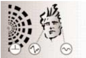
Fig. A: Natural hearing: Sound waves arriving at one ear
differ from those at the other. Amplitude and phase differences create a sense of spatial hearing.
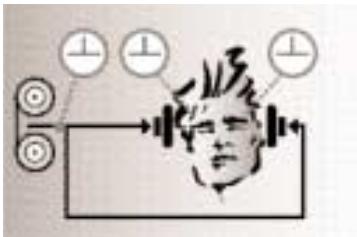
Fig. B: Listening through headphones: Amplitude and
phase differences are eliminated. Sound sources are localized inside the head rather than in the room.
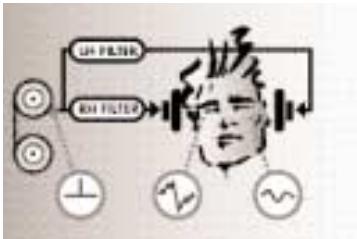
Fig. C; Listening through headphones using IVM1 and IVA: The ear matching function changes the audio signals
at the ears to resemble fig. A. This restores natural binaural, spatial hearing.
7.5. SST1 Menu Control
In the diagrams below, keys to be pressed are shown as , unpressed keys as O .
Blinking display messages appear between > and < .
Pressing the or key once decreases or increases the associated value by one step.
7.5.1. Switch-on Menu (Main Menu)
On connecting the SST1 to power, the display will show the installed software version for about 5 seconds and then change to the main menu with the settings active at the time the SST1 was last disconnected from power. It might look like this:
Depending on whether you connected a mono or stereo source, you need to switch the transmitter to mono or stereo mode:
- Press MENU.
- Press or as many times as necessary to call up this display:
| Menu: Stereo | ● | ● | |||||
| 4 | A | b | ■ | ■ | 04 | ← | → |
| EAR | SND | AMB | IVA | STEREO RFCH | LOCK | ● | ○ |
| MENU | SELECT | ||||||
- Press SELECT. The message >STEREO< will be blinking in the display:
| Stereo: >STEREO< | O | O | |||||
| 4 | A | b | ■ | ■ | 04 | ← | → |
| EAR | SND | AMB | IVA | STEREO RFCH | LOCK | O | ● |
| MENU | SELECT | ||||||
- To enter mono mode, press or . The display will change to >MONO< .
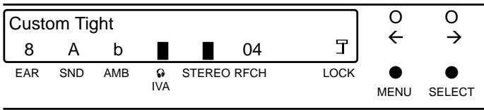
- Having selected the desired setting, press SELECT. The display will revert to the main menu. If you selected "STEREO", a solid rectangle will appear in the display above the "STEREO" label:
| Custom Tight | O | O | |||||
| 4 | A | b | ■ | 04 | ← | → | |
| EAR | SND | AMB | IVA | STEREO RFCH | LOCK | O | ● |
| MENU | SELECT | ||||||
If you selected "MONO", there will be no solid rectangle above the "STEREO" label:
| Custom Tight | O | O | |||||
| 4 | A | b | ■ | 04 | ← | → | |
| EAR | SND | AMB | IVA | STEREO RFCH | LOCK | ○ | ● |
| MENU | SELECT | ||||||
7.5.3. Sound
Selecting Sounds in Normal Mode
Eight different preset "Sounds" are stored in the transmitter's memory. Sounds A through C (Custom Tight, Medium, and Open) have been created specifically to match the supplied IP1 in-ear phones from AKG. Sounds D, E, and F (Mold Tight, Medium, and Open) have been designed for in-ear phones from other manufacturers. Sounds G and H simulate supraural headphones.
We recommend that you first find the Sound you like best.
Call up the main menu (unless it is already in the display):
- Press MENU. The main menu will appear in the display.
| Custom Tight | O | O | ||||||
| 4 | A | b | ■ | ■ | 04 | ← | → | |
| EAR | SND | AMB | IVA | STEREO RFCH | LOCK | ● | O | |
| MENU | SELECT | |||||||
Note: If you have set your transmitter to mono mode, you will see no solid rectangle above the "STEREO" label.
- Press or to select one of the eight preset Sounds. The upper display line will indicate the name of the selected Sound, for instance, this:
| Custom Tight | ● | ● | |||||
| 4 | A | b | ■ | ■ | 04 | ← | → |
| EAR | SND | AMB | ♀ | STEREO RFCH | LOCK | O | O |
| IVA | MENU | SELECT | |||||
or this:
| Mold Tight | ● | ● | |||||
| 4 | D | b | ■ | ■ | 04 | ← | → |
| EAR | SND | AMB | IVA | STEREO RFCH | LOCK | O | O |
| MENU | SELECT | ||||||
The Sound you selected becomes active immediately so you can listen to the change on the headphones. It will also be the basis for all other settings. Once you have left the main menu, you will not be able to select a different Sound. To do so, you will need to call up the main menu by pressing MENU or select the "Sound" menu.
Changing Sounds from the Sound Menu
The Sound menu provides an alternative way to change or select Sounds. If, for instance, you have called up a stored Setup (refer to section 7.5.14.), you can only change the Sound setting by calling up the Sound menu:
- Press MENU.
- Press or as many times as necessary to call up this display:
| Menu: Sound | ● | ● | ||||||
| 4 | A | b | ■ | ■ | 04 | ← | → | |
| EAR | SND | AMB | IVA | STEREO RFCH | LOCK | ● | ○ | |
| MENU | SELECT | |||||||
- Press SELECT. The display will indicate the abbreviated name of the current Sound:
| Sound: A Custom T | O | O | |||||
| 4 | A | b | ■ | ■ | 04 | ← | → |
| EAR | SND | AMB | IVA | STEREO RFCH | LOCK | ○ | ● |
| MENU | SELECT | ||||||
- Press or to select the desired Sound from the eight settings available. The upper display line will indicate the abbreviated name of each Sound, e.g., this:
| Sound: B Custom M | ● | ● | |||||
| 4 | A | b | ■ | 04 | ← | → | |
| EAR | SND | AMB | ♀ | STEREO RFCH | LOCK | ○ | ○ |
| IVA | MENU | SELECT | |||||
- Press SELECT. The lower display line will indicate the initial of the Sound you just selected above the "SND" label. The display might look like this:
| Custom Medium | O | O | |||||
| 4 | B | b | ■ | ■ | 04 | ← | → |
| EAR | SND | AMB | IVA | STEREO RFCH | LOCK | O | ● |
| MENU | SELECT | ||||||
or like this (if you were using a stored Setup):
| Set: 1 Wembley | O | O | |||||
| 8 | B | C | 06 | ← | → | ||
| EAR | SND | AMB | IVA | STEREO RFCH | LOCK | O | ● |
| MENU | SELECT | ||||||
7.5.4.Testmode
If you use the IVM1 for the first time or demonstrate it to somebody, start by selecting the appropriate ear matching function ("Ear Curve") from the "Testmode" menu.
Before calling up the "Testmode" menu check that the display indicates the Sound you liked best. (You cannot change the Sound setting in "Testmode".)
- Press MENU.
- Press or as many times as necessary to call up this display:
| Menu: Testmode | ● | ● | ||||||
| 4 | A | b | ■ | ■ | 04 | ← | → | |
| EAR | SND | AMB | IVA | STEREO RFCH | LOCK | ● | ○ | |
| MENU | SELECT | |||||||
- Press SELECT. The display will change as follows:
| Testmode: 1 Custom Tight | O | O | |||||
| ← | → | ||||||
| EAR | SND | AMB | IVA | STEREO RFCH | LOCK | O | ● |
| MENU | SELECT | ||||||
The signal will be processed by Ear preset 1 and the selected Sound.
Press or to step through and compare the various Ear pre-sets.
- Select the Ear preset that you find provides the best stereo balance and most natural sound (e.g., "4").
Once you have found your favorite Ear preset, remember its number so you can save it in memory. Do not change the Ear preset as you adjust all the other parameters.
Note: In order to get a first impression of the effect of IVA processing, you may compare the Ear preset with the unprocessed signal:
Press SELECT. The message "IVA OFF" will appear in the display and you will hear the unprocessed signal.
| IVA OFF Custom Tight | O | O | |||||
| ← | → | ||||||
| EAR | SND | AMB | IVA | STEREO RFCH | LOCK | O | ● |
| MENU | SELECT | ||||||
To switch IVA back on, press SELECT again.
- To leave the "Testmode" menu, press MENU.
7.5.5. Saving the Selected Ear Preset
- Press MENU.
- Press or as many times as necessary to call up this display:
| Menu: Ear | ● | ● | ||||||
| 4 | A | b | ■ | ■ | 04 | ← | → | |
| EAR | SND | AMB | ♀ | STEREO RFCH | LOCK | ● | ○ | |
| IVA | MENU | SELECT | ||||||
- Press SELECT. The display will change to indicate "Ear Curve" and the blinking number of the last selected Ear preset, for instance, >1< :
| Ear Curve: >1< 4 A b 04 | O ← → | ||||||
| EAR | SND | AMB | IVA | STEREO RFCH | LOCK | O MENU | SELECT |
- Press or as many times as necessary to bring up the number of your favorite Ear preset (e.g., >8< ) in the display.
- Press SELECT to save Ear preset 8. The display will revert to the main menu and indicate on the lower line the new Ear preset ("EAR8") you just saved.
| Custom Tight | O | O | |||||
| 8 | A | b | ■ | ■ | 04 | ← | → |
| EAR | SND | AMB | IVA | STEREO RFCH | LOCK | O | ● |
| MENU | SELECT | ||||||
Note: From the main menu you can compare all preset Sounds simply by pressing or . We even recommend that you do so because the Sound you originally selected may have changed slightly on selecting your favorite Ear preset.
7.5.6. IVA Demo
In order to familiarize yourself with what IVA processing does, select the "IVA Demo" menu:
- Press MENU.
- Press or as many times as necessary to call up this display:
| Menu: IVA Demo | ● | ● | ||||||
| 8 | A | b | ■ | ■ | 04 | ← | → | |
| EAR | SND | AMB | IVA | STEREO RFCH | LOCK | ● | O | |
| MENU | SELECT | |||||||
- Press SELECT to start IVA Demo:
| IVA Demo: IVA | O | O | |||||
| ← | → | ||||||
| EAR | SND | AMB | IVA | STEREO RFCH | LOCK | O | ● |
| MENU | SELECT | ||||||
The system will automatically step through the following settings and indicate each setting in the lower display line:
a) "IVA": signal processed by IVA
b) "STEREO": unprocessed stereo signal
c) "LEFT with IVA": left channel only, with IVA processing
d) "LEFT": left channel only, unprocessed signal
e) "RIGHT with IVA": right channel only, with IVA processing
f) "RIGHT": right channel only, unprocessed signal
g) Program starts over at a).
- To leave the "IVA Demo" menu press MENU. The display will indicate the message "busy" for approx. 1 or 2 seconds and revert to the main menu.
7.5.7. Ambience
The IVM1 system provides various Room simulations from a jazz club ambience to the acoustics of an open air arena.
The "Ambience" menu lets you select and activate the desired acoustics.
The ambience signals have been factory preset to a level of -12 dB. Therefore, we recommend that you set "Ambience Level" to 0 dB before comparing the individual Room simulations.
Setting Ambience Level
- Press MENU.
- Press or as many times as necessary to call up this display:
| Menu: Amb Level | ● | ● | |||||
| 8 | A | b | ■ | ■ | 04 | ← | → |
| EAR | SND | AMB | IVA | STEREO RFCH | LOCK | ● | ○ |
| MENU | SELECT | ||||||
- Press SELECT to call up the "Ambience Level" parameter. The display will indicate the current ambience signal level setting (e.g., the factory setting of -12 dB):
| Amb Level: -12 dB | O | O | |||||
| 8 | A | b | ■ | 04 | ← | → | |
| EAR | SND | AMB | IVA | STEREO RFCH | LOCK | O | ● |
| MENU | SELECT | ||||||
- Press or to adjust the ambience level in 2-dB steps between -12 dB and +12 dB (for instance, to O dB):
| Amb Level: 0 dB | O | O | |||||
| 8 | A | b | ■ | ■ | 04 | ← | → |
| EAR | SND | AMB | IVA | STEREO RFCH | LOCK | O | ● |
| MENU | SELECT | ||||||
- Press SELECT to save the desired ambience level and return to the main menu.
Comparing and Saving Room Simulations
- Press MENU.
- Press or as many times as necessary to call up this display:
| Menu: Ambience | ● | ● | |||||
| 8 | A | b | ■ | 04 | ← | → | |
| EAR | SND | AMB | IVA | STEREO RFCH | LOCK | ● | ○ |
| MENU | SELECT | ||||||
- Press SELECT. Press or to step through the Room Simulations and listen to them.
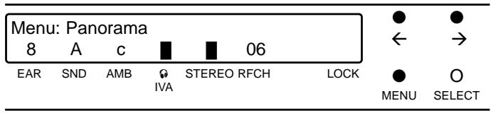
- Press SELECT to save the selected Room Simulation (e.g., "c Ambience").
| Amb.: c Ambience | O | O | |||||
| 8 | A | c | ■ | ■ | 04 | ← | → |
| EAR | SND | AMB | IVA | STEREO RFCH | LOCK | O | ● |
| MENU | SELECT | ||||||
- Set the level of the ambience signal to the desired final value referring to the para "Setting Ambience Level" above.
7.5.8. IVA
If you wish to compare the processed with the unprocessed signal while setting up the IVM1 you can defeat the IVA processing from the "IVA" menu:
- Press MENU.
- Press or as many times as necessary to call up this display:
| Menu: IVA | ● | ● | ||||||
| 8 | A | c | ■ | ■ | 04 | ← | → | |
| EAR | SND | AMB | ♀ | STEREO RFCH | LOCK | ● | ○ | |
| IVA | MENU | SELECT | ||||||
- Press SELECT to call up the menu commands:
| IVA: >ON< | O | O | |||||
| 8 | A | c | ■ | ■ | 04 | ← | → |
| EAR | SND | AMB | IVA | STEREO RFCH | LOCK | O | ● |
| MENU | SELECT | ||||||
- Press or to call up the command "IVA: >OFF< "
| IVA: >OFF< | ● | ● | ||||||
| 8 | A | c | ■ | ■ | 04 | ← | → | |
| EAR | SND | AMB | ♀ | STEREO RFCH | LOCK | ○ | ○ | |
| IVA | MENU | SELECT | ||||||
- To defeat IVA press SELECT. The command >OFF< stops blinking to indicate IVA is switched out of circuit:
| IVA OFF | O | O | |||||
| 8 | A | c | ■ | ■ | 04 | ← | → |
| EAR | SND | AMB | IVA | STEREO RFCH | LOCK | O | ● |
| MENU | SELECT | ||||||
- To switch IVA back in, repeat steps 1 to 3 above, select "IVA: >ON<", and press SELECT. The display will change to this:
| Custom Tight | O | O | |||||
| 8 | A | c | ■ | ■ | 04 | ← | → |
| EAR | SND | AMB | IVA | STEREO RFCH | LOCK | O | ● |
| MENU | SELECT | ||||||
Note: The selected setting will remain in memory even after powering down. In a multichannel IVM1 system, this allows you to switch IVA out permanently for any channel selectively if individual musicians prefer an unprocessed monitor signal.
Note: If you have selected "IVA OFF", pressing SELECT from any menu will bring up the display message "IVA OFF" rather than the main menu. To return to the main menu press MENU.
7.5.9. Mute
To mute the system completely call up the "Mute" menu:
- Press MENU.
- Press or as many times as necessary to call up this display:
| Menu: Mute | ● | ● | ||||||
| 8 | A | c | ■ | ■ | 04 | ← | → | |
| EAR | SND | AMB | IVA | STEREO RFCH | LOCK | ● | O | |
| MENU | SELECT | |||||||
- Press SELECT to call up the menu commands:
| Mute: >OFF< | O | O | |||||
| 8 | A | c | ■ | ■ | 04 | ← | → |
| EAR | SND | AMB | IVA | STEREO RFCH | LOCK | O | ● |
| MENU | SELECT | ||||||
- The or toggles between "Mute >OFF<" (normal mode) and "Mute >ON<" (system muted).
| Mute: >ON< | ● | ● | ||||||
| 8 | A | c | ■ | ■ | 04 | ← | → | |
| EAR | SND | AMB | IVA | STEREO RFCH | LOCK | ○ | ○ | |
| MENU | SELECT | |||||||
- To activate the desired setting press SELECT. If you selected > ON< the display will change as follows:
| MUTE | O | O | |||||
| 8 | A | c | ■ | ■ | 04 | ← | → |
| EAR | SND | AMB | IVA | STEREO RFCH | LOCK | O | ● |
| MENU | SELECT | ||||||
- To deactivate MUTE repeat steps 1 to 3, select >OFF<, and press SELECT.
The display will revert to the main menu.
7.5.10. RF Channel
To select the transmission channel (= the number of the desired carrier frequency) call up the "RF Channel" menu:
- Press MENU.
- Press or as many times as necessary to call up this display:
| Menu: RF Channel | ● | ● | |||||
| 8 | A | c | ■ | 04 | ← | → | |
| EAR | SND | AMB | IVA | STEREO RFCH | LOCK | ● | O |
| MENU | SELECT | ||||||
- Press SELECT.
- Press or to select one of the 16 carrier frequencies. The display will indicate the channel number (blinking) and the selected carrier frequency (e.g., 775.850 >MHz<).
| RF: >06< 775.850 >MHz< | ● | ● | |||||
| 8 | A | c | ■ | ■ | 04 | ← | → |
| EAR | SND | AMB | IVA | STEREO RFCH | LOCK | ○ | ○ |
| MENU | SELECT | ||||||
Note: Channel 16 is followed by the command "RF >OFF<". This command allows you to switch off the transmission signal.
- Press SELECT to save the selected frequency. The message "busy" will appear in the display while the frequency is being saved:
| RF: busy | O | O | |||||
| 8 | A | c | ■ | ■ | 06 | ← | → |
| EAR | SND | AMB | IVA | STEREO RFCH | LOCK | O | ● |
| MENU | SELECT | ||||||
As soon as the message "BUSY" has disappeared the display will revert to the main menu and indicate the currently active transmission channel above the "RFCH" label.
Note: If you selected >OFF< two lines will appear in the display above the "RFCH" label:
| Custom Tight | O | O | |||||
| 8 | A | C | ■ | > _ < | ← | → | |
| EAR | SND | AMB | IVA | STEREO RFCH | LOCK | O | ● |
| MENU | SELECT | ||||||
To switch the transmission signal back on, repeat steps 1 through 5 to activate a transmission channel.
7.5.11. Panorama
The "Panorama" menu allows you to adjust the apparent distance between the virtual monitors in 5 steps.
- Press MENU.
- Press or as many times as necessary to call up this display:
3. Press SELECT.
The display will change as follows:
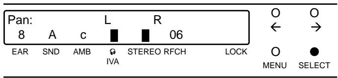
- To increase the spacing of the two L and R virtual monitors press . (Pressing from the maximum position will return the spacing to minimum.)
To decrease the spacing of the two L and R virtual monitors press . (Pressing from the minimum position will return the spacing to maximum.)
- Having found the spacing you like best, press SELECT to save the selection.
The display will revert to the main menu.
7.5.12. IVA Bypass at the PHONES Output
To listen to the unprocessed stereo signal on the transmitter you can bypass the IVA processor at the PHONES output. The transmitted signal, though, will still be processed by the selected Ear Preset. Call up the "Phones" menu:
- Press MENU.
- Press or as many times as necessary to call up this display:
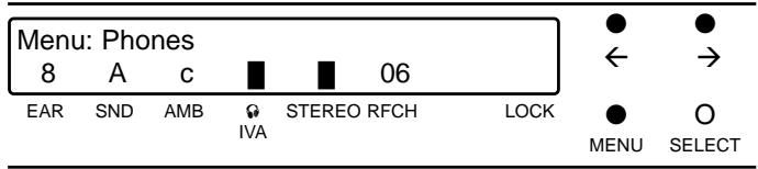
- Press SELECT to call up the menu commands:
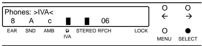
- The and keys toggle between the >IVA< and >BYPASS< commands. To bypass IVA at the PHONES output select >BYPASS< .
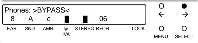
- Press SELECT.
The display will revert to the main menu and the solid rectangle above the "IVA" label will disappear. The PHONES output will carry the unprocessed stereo signal.
To activate IVA again repeat steps 1 through 5 and select >IVA < in step 4.
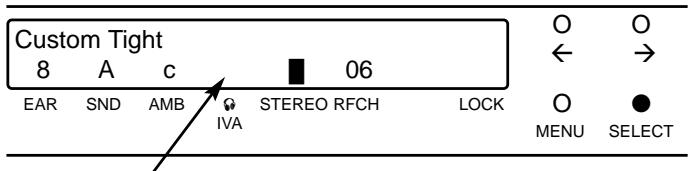
7.5.13. Save Setup
The "Save Setup" menu allows you to save all the settings you selected in menus 7.5.1 through 7.5.13 (except IVA ON/OFF, Mute, Phones Bypass, Level, Testmode, IVA Demo, and Lock) as a "Setup" at a common storage location. You may save, recall, and delete a total of eight Setups.
Finding Free Memory Locations
- Press MENU.
- Press or as many times as necessary to call up this display:
- Press SELECT.
If no Setups are stored yet the display will indicate a free storage location ("Set: >1< ) In this case skip step 4 below.
If Setups have been saved already the display will indicate the name of the first stored Setup (e.g., "Wembley"). Continue with step 4.
- Press
The display will indicate the next stored Setup. Press as many times as necessary to display a free storage location (e.g., "Set: >2< )
You can now assign a name to your Setup.
Naming and Saving Setups
- Press SELECT.
The display will indicate the number of the selected storage location (in our example, > S2 < ) followed by a cursor (_-^ ) .
| >S2<_8 A C 06 | O | O | |||||
| ← | → | ||||||
| EAR | SND | AMB | IGVA | STEREO RFCH | LOCK | O | ● |
| MENU | SELECT | ||||||
Press or to enter letters, numerals, or other characters. steps UP through the characters, DOWN. To scroll up continuously through the characters, hold down . To scroll down, hold .
- Press or as many times or hold down as long as necessary to place the desired character above the cursor. Press SELECT and enter the next character, and so on. You may enter up to 13 characters (example: "Musikverein").
| >S2< Musikverei_8 A c 06 | ●← ➔ | ||||||
| EAR | SND | AMB | IVA | STEREO RFCH | LOCK | ○MENU | ●SELECT |
Note: You can place the dash at 8 different vertical positions. This allows you to draw a rough frequency response curve.
- Having completed the name, I press SELECT as many times as necessary to move the cursor beyond the end of the line and call up this display:
| Save S2: >YES< 8 A c 06 | O O ← → | ||||||
| EAR | SND | AMB | IVA | STEREO RFCH | LOCK | O MENU | SELECT |
- If you wish to save your Setup in memory press SELECT. The display will indicate the name of the Setup you just saved:
| S2 | Musikverein | O | O | ||||
| 8 | A | c | ■ | 06 | ← | → | |
| EAR | SND | AMB | IVA | STEREO RFCH | LOCK | O | ● |
| MENU | SELECT | ||||||
- If you do NOT wish to save the Setup press (the display will change to "SAVE S2: >NO<") and SELECT. The display will revert to the main menu.
Recalling Setups
The first line of the main menu indicates either the current Sound or the current Setup.
To step through the Sounds and Settings press or . "Sound H" is followed by the first stored Setup, the last Setup by "Sound A" again.
Important: If the transmission channel number above "RFCH" starts blinking, the transmission channel stored with the selected Setup is not identical to the previously selected transmission channel. Therefore, check that the transmission channel selected on the receiver is identical to the transmitter channel. If it is not, select the same channel on both the transmitter and the receiver.
Note: You can change any parameter of the currently active Setup from the appropriate menu (e.g., "Sound", "Panorama", etc.). The lower display line indicates these
changes. All changes will be automatically deleted on disconnecting the transmitter from power.
To keep the changes, save the modified Setup either under the same name or as a new Setup with a different name.
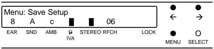
Deleting Setups
- Press MENU.
- Press or as many times as necessary to call up this display:
| Menu: Save Setup | ● | ● | |||||
| 8 | A | c | ■ | 06 | ← | → | |
| EAR | SND | AMB | IVA | STEREO RFCH | LOCK | ● | O |
| MENU | SELECT | ||||||
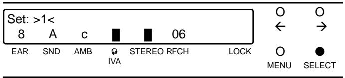
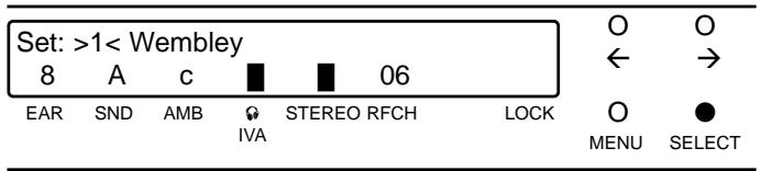
- Press SELECT.
The display will indicate the name of the first stored Setup (e.g., "Wembley").
| Set: >1< Wembley | O | O | |||||
| 8 | B | c | ■ | ■ | 06 | ← | → |
| EAR | SND | AMB | IVA | STEREO RFCH | LOCK | O | ● |
| MENU | SELECT | ||||||
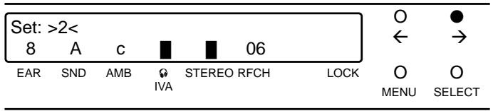
- Press to select the Setup you wish to delete (e.g., "Set: >2< Musikverein"):
| Set: >2< Musikverein | O | ● | |||||
| 8 | A | c | ■ | ■ | 06 | ← | → |
| EAR | SND | AMB | IGVA | STEREO RFCH | LOCK | O | O |
| MENU | SELECT | ||||||
- To delete the selected Setup, e.g., S2, press SELECT as many times as necessary to move the cursor to the end of the line and call up the command "Save S2: >YES<".
- Press twice.
The command "Save S2: >DELETE<" will appear in the display.
- Press SELECT.
The Setup will be deleted and the display will revert to the main menu.
7.5.14. Level
To check the input signal level call up the "Level" menu:
- Press MENU.
- Press or as many times as necessary to call up this display:
| Menu: Level | ● | ● | |||||
| 8 | A | C | ■ | ■ | 06 | ← | → |
| EAR | SND | AMB | ♀ | STEREO RFCH | LOCK | ● | ○ |
| IVA | MENU | SELECT | |||||
- Press SELECT.
The input levels in the left channel (L) and right channel (R) are displayed by horizontal rectangles in sync with the front panel IN LEVEL LEDs. A vertical line in each channel marks the threshold of the integrated limiter.
| I | L | O | O | |||
| I | R | ← | → | |||
| EAR | SND | AMB | STEREO RFCH | LOCK | O | ● |
| IVA | MENU | SELECT |
- To switch the level meter off, press SELECT, , or .
7.5.15 Lock
In order to avoid unpleasant surprises during the performance, you can protect the unit against unintentional readjustments of current settings:
- Call up the main menu.
- Simultaneously hold down MENU and SELECT for approximately 4 seconds.
A key symbol will appear above the "LOCK" label to indicate the system is locked and the keys are disabled.
In LOCK mode you can only use the and keys to toggle between the input level meter and main menu.
- To unlock the transmitter, simultaneously press MENU and SELECT for approximately 4 seconds again. The key symbol will disappear.
8. Display Error Messages
| Message | Problem | Cause | Remedy |
| "ER" message and channel number blinking alternately. | RF section switched off. | 1. No frequency data stored in Flash Memory. 2. Wrong frequency data stored in Flash Memory. | 1. Select different channel. 2. Contact your AKG dealer. |
| "RF" message and channel number blinking alternately. | No transmission signal. | Hardware defect in RF section. | Select different channel. |
| "ERROR IVA MEMORY" and "BYPASSED" messages blinking alternately. | Transmission signal and monitor signal at PHONES output without IVA. | 1. No preset data stored in Flash Memory 2. Wrong preset data stored in Flash Memory. | 1. Select different Sound, Ear, and/or Ambience settings. 2. Contact your AKG dealer. |
| "ERROR IVASIC 24" and "BYPASSED" messages blinking alternately. | Transmission signal and monitor signal at PHONES output without IVA. | IVASIC 24 chip defective. | Contact your AKG dealer. |
9. Antenna Placement
Reflections off metal parts, walls, ceiling, etc. or the shadow effects of musicians and other people may weaken or cancel the transmitter signal.
For best results, place your antenna as follows:
- Place the SST1 transmitter near the performance area. Make sure, though, that the transmitter will never get any closer to the SPR1 receiver than 10 ft (3 m). Optimum separation is 16 ft. (5 m).
- If you use a remote antenna, place it near the performance area and as high overhead as possible. Again, maintain 10 to 16 ft. (3 to 5 m) of separation.
- There should always be a direct line of sight between the transmitter and receiver.
- Place the transmitter with the screw-on antenna or the remote antenna at least 5 ft. (1.5 m) away from any big metal objects, walls, scaffolding, ceilings, etc.
- Place the SST1 transmitter at least 10 ft. (3 m) away from wireless microphone receivers (e.g., SR 300) in order to prevent any crosstalk from the in-ear monitor system into wireless microphone channels.
10. Before the Soundcheck
Before switching the sound system on, check the following:
- Make sure that the transmitter and receiver operate on the same frequency. (Refer to section 6.1.)
- Be sure to use fully charged dry or rechargeable batteries. If in doubt, insert new batteries (Refer to section 7.1.)
- Check the performance area for "dead spots", i.e., places where the field strength seems to drop and reception deteriorates. If you find any dead spots, try to eliminate them by repositioning the receiver. (Refer to section 8.)
- Check that the transmitter input signal level has been set for optimum modulation with the IN LEVEL control.
11. Protection against Hearing Damage
Do not use any other headphones than the IP1 miniature in-ear phones specifically designed by AKG for the IVM1. This is the only way to ensure that the two-stage protection system will function properly. This system comprises a limiter integrated in the transmitter and a clipping diode at the phones output on the SPR1 receiver.
If, due to malfunction, the volume shoud rise to a level that may damage your hearing, the built-in limiter will instantly reduce the level automatically.
Using any in-ear phones other than those recommended by AKG may defeat this protective function! AKG therefore declines any liability whatsoever.
Warning: Listening at excessive volume levels over an extended period of time may cause severe damage to your hearing.
12. Cleaning
To clean the surfaces of the transmitter, receiver, and earmolds, use a soft cloth moistened with methylated spirits or alcohol.
13. Accessories
13.1.RMU11 (Fig. 10)
Rack Mount Unit accepting one SST1 and AC power adapter. Provides an alternative antenna socket on the front panel.
13.2.RMU 12 (Fig.11)
Rack Mount Unit accepting two SST1 transmitters and their AC power adapters. Provides alternative antenna sockets on the front panel.
13.3. SRA1 (Fig. 12)
Remote antenna for optimum antenna placement independent of the transmitter location. Particularly recommended for use with rack mounted SST1 transmitters because it is often difficult to place a rack where it would ensure optimum UHF propagation.
13.4. Other Recommended Products
Logitek PR10 Input Extender (Fig. 14)
In a professional multichannel system, the PR10 Input Extender allows the same signal to be fed to two VMM systems simultaneously.
One VM1 functions as a backup system that can be cut in immediately if the other system should fail.
www.Logitech.com
Conex AS 101 Audio Switcher & AS 401 Remote Control (Fig. 14)
The AS 101 allows the monitor engineer to listen to the monitor mix for each artist separately.
All mixes can be selected at the push of a button either on the AS 101 itself or on the AS 401 remote control.
Suhner (Fig. 13)
Suhner makes antenna cables of extremely high quality. Thanks to their extremely low attenuation, these allow longer cable runs than standard types with almost zero signal loss.
www.hubersuhner.com
Directional Antenna (Fig. 15)
For applications where the mixing position is more than 200 ft. or 230 ft. away from the stage, we recommend to use directional antennas, for instance, the Hirschmann model shown in fig. 15. These antennas will increase the range of the transmitter without the need for extremely long antenna cables. Ask your AKG dealer for more information.
www.hirschmann.com
14. Specifications
14.1. SST1 Stationary Stereo Transmitter
| IVM1 carrier frequencies | 16 frequencies within the 766 to 877 MHz and 844 to 950 MHz UHF ranges |
| Selection bandwidth | up to 20 MHz |
| Modulation | FM |
| Frequency stability | 0.002% |
| Rated deviation | ±30 kHz for 1-kHz sine-wave audio signal |
| RF radiation (50 Ω) | 50 mW; DE, DE1: 20 mW; DK, DK2: 10 mW |
| Antenna connector | BNC socket; 50 Ω |
| Audio bandwidth | 50 to 15,000 Hz |
| T.H.D. at 1 kHz | 0.5% at rated deviation |
| Compander system | rms characteristic |
| Preemphasis | 50 msecs. |
| Signal/noise | 80 dB(A) |
| Input level | 10 dBm max., adjustable |
| Input impedance | >22 kΩ |
| Current consumption | 0.4 to 0.8 A |
| Power requirement | 100 to 240 VAC, 50/60 Hz |
| Size (VxDxH) | 210 x 283 x 41 mm / 8.3 x 11.1 x 1.6 in. (inc. controls, exc. of antenna) |
| Net weight | 1860 g (4.1 lbs.) |
| LEVEL LEDs | <-50 DBV dark >50 dBV green -8 dBV orange (limiter threshold) >16 dBV red |
| ADC, DAC | 18-bit |
| ASIC chip internal computing accuracy | 24-bit (144 dB dynamic range) |
| Sampling frequency | 44.1 kHz |
| Computing power | 500 Taps |
| 14.2. SPR1 Stereo Bodypack Receiver | |
| IVM1 carrier frequencies | 16 frequencies within the 766 to 877 MHz and 844 to 950 MHz UHF ranges |
| Selection bandwidth | up to 20 MHz |
| Adjacent channel selection | 60 dB typ. |
| Image rejection | 50 dB typ. |
| Antenna | screw-on type |
| Rated deviation | ±30 kHz for 1-kHz sinewave audio signal |
| Compander system | rms characteristic; switchable |
| Audio bandwidth | 50 to 15,000 Hz |
| T.H.D. at 1 kHz | <1% at rated deviation (L = R; 0.6% typ.) |
| Signal/noise at 30 kHz deviation and -50 dBm RF level | 70 dB(A) |
| Signal/noise at 30 kHz deviation and -90 dBm RF level | 50 dB(A) |
| Audio output | mini stereo jack, adjustable from 0 to 0.8 V rms into 50 Ω |
| Current consumption | 160 mA typ. |
| Power supply | 3 x 1.5-V AA size batteries |
| Size (exc. of antenna) | 69 x 18 x 94 mm / 2.7 x 0.7 x 3.7 in.(W x H x D) |
| Net weight | approx. 230 g / 8.1 oz. |
| Mono/stereo threshold | -80 dBm typ. |
| Channel separation | >40 dB |
| Squelch threshold | -95 dBm (fixed) |
| Battery status indications | POWER:LED lighting green: battery voltage O.K. POWER:LED blinking green: battery voltage below 3.25 V |
| Peak LED | 0 - 100 mV: dark 100 mV - 2 V rms: green >2 V rms: red |
| 14.3. IP1 In-ear Phones | |
| Type | dynamic |
| Frequency range | 20 Hz to 20,000 Hz |
| Sensitivity | >100 dB/mW |
| Power handling capability | 50 mW |
| Rated impedance | 50 Ω |
| Weight (inc. cable) | 20 g (0.7 oz.) |
| Cable | 1.5 m (5 ft.), Y-connected |
| Connector | stereo mini jack plug |
| 14.4. IVM1 System | |
| Shipping weight | approx. 3 kg (6.7 lbs.) |
| Package size (L x W x H) | 410 x 310 x 90 mm (16.1 x 12.2 x 3.5 in.) |
| Temperature range | -10°C to +55°C |
| Declaration of conformity: | available on request |
Table des matieres
| I | L | O | O | ||||
| I | R | ← | → | ||||
| EAR | SND | AMB | IVA | STEREO RFCH | LOCK | O MENU | ● SELECT |
6b POWER I/O: interruptore on/off
| I | L | O | O | ||||
| I | R | ← | → | ||||
| EAR | SND | AMB | IVA | STEREO RFCH | LOCK | O | ● |
| MENU | SELECT |
LED POWER (6c) | LED MUTE (6a) | LED Peak (6d)
Emite luz verde:
| I | L | O | O | ||||
| I | R | ← | → | ||||
| EAR | SND | AMB | IVA | STEREO RFCH | LOCK | O | ● |
| MENU | SELECT |
| I | L | O | O | ||||
| I | R | ← | → | ||||
| EAR | SND | AMB | IVA | STEREO RFCH | LOCK | O | ● |
| MENU | SELECT |
- Inhalt
- Contents
- Introduction
- Precautions
- SST1 Stationary Stereo Transmitter
- Controls
- Front Panel (Fig. 1)
- Rear Panel (Fig. 2)
- Standard Accessories
- Optional Accessories
- SPR1 Stereo Bodypack Receiver
- Controls
- Figure 6
- Figure 7
- Figure 8
- Standard Accessories
- IP1 In-ear Phones
- 5.1.Standard Accessories
- Optional Accessories
- Frequencies
- Frequency Sets
- Ordering Transmitters and Receivers
- Selecting Frequencies on the SST1
- Selecting Frequencies on the SPR1
- Setting Up
- SPR1 Receiver
- Inserting/Replacing the Batteries
- Powering Up
- SST1 Transmitter
- Battery Life
- IVA - Individual Virtual Acoustics
- How IVA Works
- SST1 Menu Control
- Switch-on Menu (Main Menu)
- Sound
- Selecting Sounds in Normal Mode
- Changing Sounds from the Sound Menu
- 7.5.4.Testmode
- Saving the Selected Ear Preset
- IVA Demo
- Ambience
- Comparing and Saving Room Simulations
- IVA
- Mute
- RF Channel
- Panorama
- Press SELECT.
- IVA Bypass at the PHONES Output
- Save Setup
- Finding Free Memory Locations
- Naming and Saving Setups
- Recalling Setups
- Deleting Setups
- Level
- Lock
- Display Error Messages
- Antenna Placement
- Before the Soundcheck
- Protection against Hearing Damage
- Cleaning
- Accessories
- 13.1.RMU11 (Fig. 10)
- 13.2.RMU 12 (Fig.11)
- SRA1 (Fig. 12)
- Other Recommended Products
- Logitek PR10 Input Extender (Fig. 14)
- Conex AS 101 Audio Switcher & AS 401 Remote Control (Fig. 14)
- Suhner (Fig. 13)
- Directional Antenna (Fig. 15)
- Specifications
- Table des matieres
- LED POWER (6c) | LED MUTE (6a) | LED Peak (6d)
- Emite luz verde:
Brand : AKG
Model : IVM 1
Category : Wireless audio equipment