
AS 4+3 - Audio Amplifier AKG - Free user manual and instructions
Find the device manual for free AS 4+3 AKG in PDF.


| Brand | AKG |
| Model | AS 4+3 |
| Product Type | Automatic Mixing Console |
| Dimensions | 483 x 44 x 180 mm |
| Weight | 2.5 kg |
| Power Supply | 12 V AC power adapter, max power consumption 5 W |
| Main Functions | 4 microphone inputs with noise gate and compressor/limiter, 3 line inputs, switchable 24 V phantom power per channel, Ducking function (channel 1 priority), automatic NOM attenuation, cascading up to 10 units (40 microphone inputs) |
| Maintenance and Cleaning | Disconnect the power adapter before cleaning. Use a slightly damp cloth. Do not use abrasive products, alcohol or solvent. |
| Safety | Do not use in a humid environment. Do not open the device. Check that the adapter voltage matches the mains voltage. Disconnect if not in use for a long period. |
| Spare Parts and Repairability | Repair and maintenance reserved for authorized technical personnel. Power adapter included. IC AS8 link cable optional. |
| General Information | Reference: 6000H1893. Microphone bandwidth: 20 Hz - 35 kHz. Signal-to-noise ratio: 75 dB. |
Frequently Asked Questions - AS 4+3 AKG
User questions about AS 4+3 AKG
0 question about this device. Answer the ones you know or ask your own.
Ask a new question about this device
Download the instructions for your Audio Amplifier in PDF format for free! Find your manual AS 4+3 - AKG and take your electronic device back in hand. On this page are published all the documents necessary for the use of your device. AS 4+3 by AKG.
USER MANUAL AS 4+3 AKG
Please read the manual before using the equipment!
1 Safety and Environment. 9
1.1 Safety 9
1.2 Environment. 10
2 Description 10
2.1 Introduction 10
2.2 Unpacking 10
2.3 Optional Accessories 10
2.4 Front Panel. 10
2.4.1 Microphone Input Controls 10
2.4.2 Line Input Controls 11
2.4.3 MASTER OUTPUT CONTROLS. 11
2.4.4 Power Switch 11
2.5 Rear Panel 11
2.5.1 EXPANSION Connections 11
2.5.2 CONTROL MODE Section 11
CONTROL MODE Switches 11
CONTROL MODE Trimmers 12
2.5.3 Outputs. 12
2.5.4 Line Inputs. 12
2.5.5 Microphone Inputs. 12
2.5.6 Power Input. 12
2.5.7 Block Diagram. 12
3 Interfacing. 12
3.1 Audio Connections. 12
3.2 Daisy-chaining Several AS 4+3 Mixers 13
3.3 Connecting to Power 13
4 Operating Instructions. 13
4.1 Setting Microphone Levels. 13
4.1.1 Automatic Mode 13
4.1.2 Setting Hold Time 14
4.1.3 Balancing Microphone Sensitivities 14
4.2 Setting Line Levels. 14
4.3Activating Ducking Mode 14
4.3.1 Setting Ducking Attenuation. 14
4.4 Output Level and Equalizer 14
4.5 NOM Attenuation 14
5 Cleaning 14
6 Specifications 15
6.1 Microphone Inputs 15
6.2 Line Inputs. 15
6.3 System. 15
6.4 Ordering Information/Item Number. 15
6.5 Architects' and Engineers' Specifications 15
1 Safety and Environment

- Spill no liquids on the equipment and do not drop any objects through the ventilation slots in the equipment.
- The equipment may be used in dry rooms only.
- The equipment may be opened, serviced, and repaired by authorized personnel only. the equipment contains no user-serviceable parts.
- Before connecting the equipment to power, check that the AC mains voltage stated on the supplied AC adapter is identical to the AC mains voltage available where you will use the equipment.
- Operate the equipment with the supplied 12-V AC adapter. Using adapters with a DC output and/or a different output voltage may cause serious damage to the unit.
- If any solid object or liquid penetrates into the equipment, shut down the sound system immediately. Disconnect the AC adapter from the power outlet immediately and have the equipment checked by AKG service personnel.
- If you will not use the equipment for a long period of time, disconnect the AC adapter from the power outlet. Please note that the equipment will not be fully isolated from power when you set the power switch to OFF.
- Do not place the equipment near heat sources such as radiators, heating ducts, or amplifiers, etc. and do not expose it to direct sunlight, excessive dust, moisture, rain, mechanical vibrations, or shock.
- To avoid hum or interference, route all audio lines, particularly those connected to the microphone inputs, away from power lines of any type. If you use cable ducts, be sure to use separate ducts for the audio lines.
- Clean the equipment with a moistened (not wet) cloth only. Be sure to disconnect the AC adapter from the power outlet before cleaning the equipment! Never use caustic or scouring cleaners or cleaning agents containing alcohol or solvents since these may damage the enamel and plastic parts.
1.1 Safety
1.2 Environment
- The AC adapter will draw a small amount of current even when the equipment is switched off. To save energy, disconnect the AC adapter from the power outlet if you will leave the equipment unused for a long period of time.
- When scrapping the equipment, separate the case, circuit boards, and cables, and dispose of all components in accordance with local waste disposal rules.

2 Description
2.1 Introduction
Dear Customer:
Thank you for purchasing an AKG product. This Manual contains important instructions for setting up and operating your equipment. Please take a few minutes to read the instructions below carefully before operating the equipment. Please keep the Manual for future reference. Have fun and impress your audience!
The AS 4+3 is an automatic mixer with four gated microphone inputs and three line inputs, a balanced line output and an unbalanced output for connecting an audio recording device.
Each microphone input provides switchable 24-V phantom power for condenser microphones and a separate compressor/limiter.
A switchable ducking ("priority") mode reduces the gain of all inputs for as long as signal is present in MIC channel 1.
An NOM attenuation function reduces the output level by approx. 2 dB every time the number of open microphones doubles.
Special rear panel EXPANSION connectors allow you to "daisy-chain" up to ten AS 4+3 mixers providing up to forty microphone inputs.
2.1 Unpacking
1 AS 4+3
1 AC Adapter
2.3 Optional Accessories
Check that the package contains all the parts listed above. If anything is missing, please contact your AKG dealer.
IC AS8 connecting cable for daisy-chaining two to ten AS 4+3 mixers.
2.4 Front Panel
MK 9/10 microphone cable: 10-m (30-ft.) 2-conductor shielded cable with male and female XLR connectors.
2.4.1 Microphone Input Controls
Refer to Fig. 2.
Refer to Fig. 1.
THRESHOLD: This trimmer pot sets the threshold above which the input channel will open automatically. (As long as the microphone level is below the threshold, the input level is attenuated by 14 to 26 dB.) The control range is from approx. 0 dB to -32 dB with reference to the nominal input level.
With the THRESHOLD pot turned fully CCW, the threshold is approx. -32 dB. The input level detector is very sensitive and the channel will open even if you speak into the microphone rather softly.
The further you turn THRESHOLD CW, the less sensitive the level detector will be and the louder you will have to speak into the microphone to switch the input channel on. With THRESHOLD fully CW, the threshold level will be above 0 dB. In this setting, it is almost impossible to open the channel by talking into the microphone.
Since the THRESHOLD control is not affected by the LEVEL setting a channel may come on even if the LEVEL control is set to minimum. Although the microphone signal in that channel will remain inaudible, the channel is actually open and adds to the number of open microphones (NOM) so it may trigger (or increase) NOM attenuation (see also section 4.5). To avoid this effect, turn THRESHOLD up CW far enough to prevent the channel from coming on inadvertently.
ON: This blue LED will light to indicate the channel is on. It extinguishes when the channel switches off.
LEVEL: This rotary control sets the volume level of the channel..
COMP/LEVEL: This trimmer pot sets the compression ratio. With the COMP/LEVEL pot fully CCW there will be nearly no compression and channel gain will be independent of the input level. When you set COMP/LEVEL fully CW, the input signal will be compressed at a ratio of approx. 2:1. This means if the input signal level rises by 2 dB the output level will rise by only 1 dB.
Compression will keep the output level fairly constant even if the talker frequently moves closer to or further away from the microphone. We therefore recommend to turn up COMP/LEVEL for talkers with little experience of using microphones.
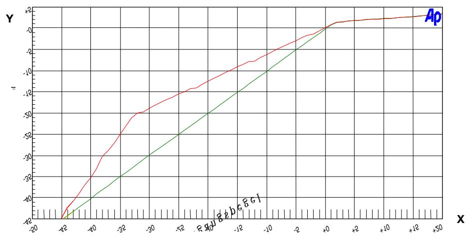
Diagram 1 shows the ratio of the input level (X axis) and output level (Y axis). The upper trace was recorded at maximum compression and the lower trace shows linear gain. The diagram also shows how the limiter prevents the output level from rising above 0 dBu.
LEVEL: This rotary control sets the volume level of the input channel.
The MASTER OUTPUT controls affect the main output (LINE OUTPUT) only and do not affect the signal at the REC OUT jacks.
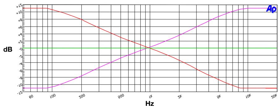
BASS: This rotary control provides approx. 10 dB of shelving low-frequency cut or boost at 100Hz .
TREBLE: This rotary control provides approx. 10 dB of shelving high-frequency cut or boost at 10 kHz.
OUTPUT LEVEL: This rotary control sets the volume level of the LINE OUTPUT.
POWER: Switches power to the mixer on (position "1") and off (position "0").
The green ON LED next to the POWER switch will illuminate to indicate the mixer is ON.
Refer to Fig. 6.
EXPANSION IN/OUT: These two 8-pin mini DIN sockets (also known as Hosiden or S-VHS sockets) let you daisy-chain up to 10 AS 4+3 automatic mixers. For this purpose you will need one or more optional IC AS8 connecting cables from AKG. You can set the CONTROL MODE functions on each mixer in the chain individually and the output parameters for all mixers on the last mixer in the chain only.
Refer to Fig. 8.
DUCKING MASTER: This DIP switch activates and deactivates the ducking function.
ON: As long as the MIC 1 microphone channel is active, the level of all other input channels (MIC 2 to 4 and LINE 1 to 3) on this and any other mixers that may be connected to it will be reduced.
OFF: The status of the MIC 1 channel does not affect the other channels.
GROUND CONNECT: As long as this switch is in the ON position (down) the metal case of the mixer is electrically connected to ground and the shield connections of all input and output sockets. We recommend that you always leave GROUND CONNECT in the ON position. However, if you connect the mixer to other equipment that is grounded, too you may end up with a ground loop that causes hum. You can eliminate the ground loop (and the hum) by setting GROUND CONNECT to OFF (up).
Diagram 1: Compression.
2.4.2. Line Input Controls
Refer to Fig. 3.
2.4.3 MASTER OUTPUT CONTROLS
Refer to Fig. 4.
Diagram 2: Equalizer characteristics.
2.4.4 Power Switch
Refer to Fig. 5.
2.5 Rear Panel
2.5.1 EXPANSION Connections Refer to Fig. 7.
2.5.2 CONTROL MODE Section
CONTROL MODE Switches
| CONTROL MODE Trimmers | HOLD TIME 4s and HOLD TIME 8s: These two switches allow you to set the amount of time (1 to 12 seconds) for which the MIC inputs will remain on after the talker has stopped talking (see also section 4.1.2). |
| DUCKING ATTENUATION: This trimmer pot sets the amount by which the mic input channels MIC 2-4 and the line input channels LINE 1-3 are attenuated when MIC 1 places the mixer in Ducking mode. The control range is 20 dB (full CCW) to approx. 9 dB (full CW). DUCKING ATTENUATION thus lets you define, for instance, how much quieter background music from a CD player will be heard while MIC 1 is being talked into. | |
| GATEATTENUATION: This trimmer pot sets the amount by which all microphone input channels (MIC 1 to 4) are attenuated when there is no activity in them. The control range is from 26 dB (full CCW) to approx. 14 dB (full CW). GATE ATTENUATION thus allows you to define how loudly the microphone signal in a channel will still be audible even if that channel is off. This is rather important in discussi-ons because a certain amount of ambient sound will remain audible even when nobody talks. | |
| 2.5.3 Outputs Refer to Fig. 9. | LINE OUTPUT: This XLR connector provides the electronically balanced, combined output signal of all input channels. You can use the front panel OUTPUT LEVEL control to set the output level. The nominal output level is approx. 0 dBu. |
| REC OUT: These two RCA jacks provide an unbalanced feed for a cassette deck or other recording equipment. The REC OUT jacks carry the output signal of all input channels. The signal at the REC OUT jacks is not affected by the MASTER OUTPUT controls (BASS, TREBLE, and OUTPUT LEVEL). The output level is approx. 0 dBu. | |
| 2.5.4 Line Inputs Refer to Fig. 10. | LINE IN 1 to 3: These three sets of two RCA jacks each allow you to connect external audio sources such as CD players, tuners, cassette decks, etc. Stereo signals are automatically summed to mono. The nominal input level is -10 dBu. |
| 2.5.5 Microphone Inputs Refer to Fig. 11. | MIC 1 INPUT to MIC 4 INPUT: Balanced XLR sockets for connecting low-impedance dynamic or condenser microphones. |
| PHANTOM PWR: This DIP switch switches phantom power for the channel on (lower position) and off (upper position). | |
| +20 dB: In its lower position, this DIP switch increases the input gain by 20 dB (making the signal louder). With the +20 dB switch in its upper position, the input gain will remain unchanged (refer to Table 1 in section 4.1). | |
| PERMANENT ON: Toggles between Auto and Manual modes. Upper position - Auto mode: The channel will open automatically as soon as activity (e.g., some-body talking into the microphone) is detected at the input. If no activity is detected, the channel will automatically switch off after a delay you can set with the HOLD TIME switches. | |
| Note: | The gates will not switch the microphone channels off completely but attenuate them by 14 to 26 dB. To keep input signals inaudible, turn the appropriate LEVEL control(s) on the front panel all the way CCW. |
| Lower position - Manual mode: the channel is permanently open irrespective of the input signal. | |
| GAIN: This trimmer pot fine adjusts input gain (see also Table 1 in section 4.1). | |
| 2.5.6 Power Input Refer to Fig. 12. | AC INPUT: Input jack for the supplied AC adapter. |
| Important! | Operate the mixer with the supplied AC adapter (12 V AC) only. Operating the mixer with a dif-ferent power supply or on DC may damage the equipment. |
| 2.5.7 Block Diagram | Refer to Fig. 13. |
| 3 Interfacing | |
| 3.1 Audio Connections | Make all audio connections before connecting the mixer to power. |
| Refer to Fig. 14 for a wiring example. | |
| 1. Connect your microphones to the rear panel MIC INPUT connectors. Refer to the instruction manual(s) of your microphones. | |
| Note: | Connect the microphone that will control ducking to MIC 1 INPUT. |
| 2. On each channel to which you connected a condenser microphone, switch phantom power on by setting the PHANTOM PWR switch to its lower position. | |
| Important! | If you use wireless microphones, be sure to switch phantom power off on each channel to which you connected a receiver. The phantom voltage may damage the receiver. |
| 3. Connect your audio sources (CD-Player etc.) to the LINE inputs using (optional) RCA cables. | |
You can connect together ("daisy-chain") up to ten AS 4+3 mixers. This provides a maximum of 40 microphone and 30 line inputs.
- Use an optional IC AS8 connecting cable to connect the EXPANSION OUT socket on the first mixer to the EXPANSION IN socket on the next mixer and so on.
All CONTROL MODE controls affect the parameters of the same mixer only, so you can set, say, a different hold time on each mixer.
Also, you can define MIC 1 INPUT as the Ducking Master channel on any one, or even several, of the daisy-chained mixers. Several Ducking Master channels will not interfere with one another, although any one of them will cause all "normal" channels to be attenuated.
The combined output signal of all input channels on all mixers is available on the REC OUT and LINE OUTPUT connectors on the last mixer, i.e., the one whose EXPANSION OUT is not connected to another mixer.
The MASTER OUTPUT controls (BASS, TREBLE, and OUTPUT LEVEL) are only active on the last mixer. On all previous mixers, REC OUT and LINE OUTPUT are muted and the MASTER OUTPUT controls (BASS, TREBLE, and OUTPUT LEVEL) disabled!
Check that the AC mains voltage stated on the supplied AC adapter is identical to the AC mains voltage available where you will use your system. Using the AC adapter with a different AC voltage may cause damage to the unit.
- Connect the cable on the supplied AC adapter to the AC INPUT jack on the rear panel of the mixer.
- Connect the AC adapter to a convenient power outlet.
- Set the POWER switch to "I" to switch power to the mixer on. The ON LED next to the POWER switch will illuminate.
3.2 Daisy-chaining Several AS 4+3 Mixers
3.3 Connecting to Power Important!
Refer to Fig. 12.
4 Operating Instructions

- Turn the LEVEL and COMP/LEVEL controls on the front panel fully CCW and THRESHOLD fully CW.
- Set the OUTPUT LEVEL control in the MASTER OUTPUT CONTROL section on the front panel to maximum and BASS and TREBLE to twelve o'clock.
- Set the +20 dB switch to "OFF" (up) and turn GAIN fully CCW.
- Switch the first microphone channel on by setting the appropriate PERMANENT ON switch on the rear panel to its lower position.
- Turn the front panel LEVEL control for the same microphone channel up CW as far as possible without causing feedback (howling noise from the speakers).
- Talk into the microphone. If the signal is too quiet, you can use the +20 dB switch and the GAIN control to increase input sensitivity to -50 dB max.:
| +20 dB | GAIN | Resulting Input Sensitivity |
| OFF | Full CCW | -10 dBu (very low) |
| OFF | Full CW | -30 dBu |
| ON | Full CCW | -30 dBu |
| ON | Full CW | -50 dBu (maximum) |
- Repeat steps 3 through 6 for all other microphone channels.
If the talker moves closer to or further away from the microphone the signal level will vary accordingly. To compensate for such level variations, you can set COMP/LEVEL to a medium or high position (maximum compression ratio is 2:1).
- Set the PERMANENT ON switch on the rear panel to its upper position.
- Turn the front panel THRESHOLD control CW to the point that the microphone channel will open as soon as somebody talks into the microphone.
4.1 Setting Microphone Levels
Refer to Fig. 2.
Refer to Fig. 4.
Refer to Fig. 11.
Table 1: Setting input sensitivity.
Note:
4.1.1 Auto Mode
Refer to Fig. 11.
Refer to Fig. 2.
Make sure not to turn up THRESHOLD far enough for ambient noise to activate the channel.
The microphone channel will switch off approximately 1 second after the talker has stopped talking. You can increase this hold time using the HOLD TIME switches.
- To increase the hold time for all microphone channels to a maximum of 12 seconds, set the HOLD TIME switches in the CONTROL MODE section on the rear panel as follows:
Table 2: Available hold time settings.
| HOLD TIME 4s | HOLD TIME 8s | Resulting Hold Time |
| OFF | OFF | Minimum, approx. 1 sec. |
| ON | OFF | 4 secs. |
| OFF | ON | 8 secs. |
| ON | ON | 12 secs. |
The HOLD TIME switches affect all microphone channels on the same mixer (and none of the microphone channels on any other daisy-chained mixer). In Ducking mode (DUCKING MASTER switch ON), the hold time of MIC 1 INPUT is always 1 second, irrespective of the HOLD TIME setting.
Important!
4.1.2 Setting Hold Time
| 4.1.3 Balancing Microphone Sensitivities Refer to Fig. 11. | Auto mode allows you to compensate for the differences in sensitivity between two or more microphones: 1. Set up the input channel for each microphone referring to section 4.1.1 above. 2. Switch each microphone channel to Auto mode by setting the appropriate PERMANENT ON switch to its upper position. 3. Place all microphones at exactly the same distance from a talker. 4. Ask the talker to produce a sustained sound, for instance, a whistle, and make it grow louder gradually. 5. Set the appropriate GAIN controls such that all microphone channels involved will open simultaneously (at the same sound pressure level). |
| 4.2 Setting Line Levels Refer to Fig. 3. | 1. Set the LEVEL control of the LINE input channel for each audio source to the desired volume level. |
| 4.3 Activating Ducking Mode Refer to Fig. 8. | 1. Set the DUCKING MASTER switch in the CONTROL MODE section on the rear panel to its lower position. As soon as MIC 1 INPUT comes on, the volume level of all other microphone and line inputs will be attenuated automatically. |
| 4.3.1. Setting Ducking Attenuation Refer to Fig. 8. | 1. Set the DUCKING ATTENUATION trimmer pot to the desired attenuation value. The control ranges from 20 dB (full CCW - high attenuation) to 9 dB (full CW - low attenuation). |
| 4.4 Output Level and Equalizer Refer to Fig. 4. | 1. Use the OUTPUT LEVEL control (in a daisy-chain configuration, on the last mixer) to set the main output level of the mixer (the combined output signal level of all mixers). 2. Set BASS and TREBLE to 12 o'clock. In this position, the equalizer will not change the output signal. To cut the high or low frequencies, turn TREBLE or BASS CCW. To boost the high or low frequencies, turn TREBLE or BASS CW. |
| 4.5 NOM Attenuation | The AS 4+3 will automatically attenuate the output level by an amount depending on the Number of Open Microphones (hence "NOM attenuation"). Every time the number of open microphone doubles, system gain is reduced by approx. 2 dB. (In a daisy-chain configuration, it makes no difference on which mixer a channel comes on.) As a result, the risk of feedback (howling) will hardly grow even if the number of open microphones changes. |

5 Cleaning
Important!
Never use caustic or scouring cleaners or cleaning agents containing alcohol o solvents since these may damage the enamel or plastic parts.
| Type | balanced and RF filtered | |
| Impedance | approx. 2.4 k at any level | |
| Nominal level | -50 to -10 dBu, adjustable in two sub-ranges | |
| S/N ratio | 75 dB (20 Hz to 22 kHz, rms) | |
| Max. input level | +5 dBu | |
| Turn-on threshold | -32 to 0 dB re nominal input level | |
| Hold time | 1/4/8/12 secs. ±20% | |
| Gate attenuation | 14 to 26 dB, adjustable | |
| Compression ratio | linear to 2:1, adjustable | |
| Audio bandwidth | 20 Hz to 35 kHz | |
| NOM attenuation | 1 microphone: 0 dB | 5 microphones: -7.2 dB |
| 2 microphones: -2.1 dB | 6 microphones: -8.6 dB | |
| 3 microphones: -4 dB | 7 microphones: -9.9 dB | |
| 4 microphones: -5.5 dB | 8 microphones: -11 dB | |
| Phantom power | 24 V, switchable on each channel (Ri = 2 x 1.2 k ) | |
| Type | unbalanced and RF filtered | |
| Impedance | >35 k | |
| Nominal level | -10 dBu | |
| S/N ratio | 75 dB (20 Hz to 22 kHz, rms) | |
| Audio bandwidth | 20 Hz to 45 kHz | |
| Max. input level | +5 dBu | |
| Max. gain | 55 dB (input to main output) | |
| Ducking attenuation | 9 dB to 20 dB, adjustable | |
| THD | <0.1%; at any level setting | |
| IM distortion | <0.1%; at any level setting | |
| Power requirement | 5 W max. at 12 V AC | |
| Weight | 2.5 kg / 5.5 lbs. | |
| Size | 483 x 44 x 180 mm / 19 x 1.7 x 7 in. | |
| AS 4+3 | 6000H1893 | |
The mixer shall be an automatic mixer capable of being daisy-chained, with four gated microphone inputs and three line inputs. The microphone inputs shall provide 24-V phantom power and a compressor/limiter separately adjustable for each channel. The device shall be fitted with microphone inputs and a line output on 3-pin XLR connectors and line inputs and recording outputs on RCA jacks. A switchable ducking function shall cause all other channels to be attenuated while there is activity in the MIC 1 channel. The mixer shall be fitted with a two-band equalizer (bass and treble) affecting only the main output signal.
6.1 Microphone Inputs
6.2 Line Inputs
6.3 System
6.4 Ordering Information/Item Number
6.5 Architects' and Engineers' Specifications
Page
L'appareil devra always be used with the help of a suitable adaptation.
Voir Fig. 13.
Réglages CONTROL MODE
2.5.3 Sorties Voir Fig. 9.
Brand : AKG
Model : AS 4+3
Category : Audio Amplifier