USER MANUAL HM 550 KRESS
Operating Instructions GB 7
Mode d'emploi F 10
The pneumatic drill hammer is universally usable for hammer drilling and drilling as well as for screwdriving in wood, metal and plastic.

This pneumatic drill hammer is not suited for chiselling work (also not with pointed chisels).
1

Safety Instructions and Accident Prevention
Before putting the machine into operation, read through these operating instructions completely and observe the safety instructions contained therein as well as those in the enclosed booklet on general safety instructions for electro-tools.
If the mains cable is damaged while working, pull the mains plug immediately.
Never work with a damaged mains cable.
A Wear protective glasses, hearing protection, protective gloves and sturdy shoes.
A Wear hearing protection. Exposure to noise can cause hearing loss.
A Use the auxiliary handles supplied with the machine. Loss of control can cause personal injury.
A Do not work with materials containing asbestos.
Do not carry the machine by the cable.
The mains receptacles in the working area must be protected by a residual current circuit breaker (RC).
For the attachment of identification markings on the machine, do not drill into the housing. The protective insulation would be shorted. Use stickers.
When the drill unexpectedly jams, the machine kicks back. Therefore, always take a secure stance and hold the machine firmly with both hands.
2 Illustration
1 Tool holder
2 Dust protection cap
3 Unlocking collar
4 Clamping screw for auxiliary handle/depth stop
5 Ventilation slots
6 Rotational direction switch
7 Locking button for on/off switch
8 On/Off switchr
9 Ventilation slots
10 Drilling/Impact drilling selector
11 Depth stop
12 Auxiliary handle
13 Adapter for screwdriver bits/drill chuck
Accessories illustrated or described are not always included as standard delivery items.
3 Technical Data
Pneumatic Drill Hammer
Article number
Input power
Output power
Half-wave control
No-load speed
Speed under load
No-load impact rate
Load hammer blows
Impact energie
Right/Left rotation
Clamping collar dia.
Tool holder
HM 550
0428 3226
550 Watt
270 Watt
0-1000 RPM
0-750 RPM
max. 4950 RPM
max.approx.4100 RPM
max.2.0J
43 mm Euro standard
SDS-Plus
Drill dia., max.
Steel
Light metal
Wood
Hammer drilling in
concrete
Recommended hammer
drilling range
13 mm
16 mm
30 mm
20 mm
5-14 mm
Screw dia., max.
Wood
Sheet metal
6 mm
6.3 mm
Corner measure
Weight
Protection class
33 mm
2.2 kg
II/回
Measured values determined according to EN 60 745.
Typically the A-weighted noise levels of the machine are: sound pressure level 94 dB (A); sound power level 105 dB (A). Measurement uncertainty K = 3 dB.
Wear hearing protection!
The typically weighted acceleration is 8,1m / s^2


8 English
HM 550
Mounting the Auxiliary Handle, Powersupply Cord
Before any work on the machine itself, pull the mains plug!
Operate the machine only with the auxiliary handle 12. Place the auxiliary handle on the clamping collar and tighten with the clamping screw.
Damaged mains cables must not be used. They must be replaced without delay by an authorised servicing agent (heavy rubber sheathed code designation H 07 RN-F).
6 Putting into Operation
Check before putting into operation that the mains voltage agrees with the voltage specified on the nameplate of the machine.
SWITCHING ON/OFF
Press or release the on/off switch 8.
The on/off switch can be locked on with the locking button 7. To release, briefly press and release the on/off switch 8.
DRILLING - IMPACT DRILLING
For drilling, place the selector 10 in the position. For impact drilling, set to
The switch-over can best be performed at a standstill. Only after the on/off switch 8 is actuated and the machine starts does the gear box shift to the selected mode.
Note: Left rotation when impact drilling damages the drill. Switch off the impact mechanism for diamond crown drilling or for mixing work.
When hammer drilling, use exclusively drills with hard metal inserts and SDS-Plus shafts. The use of commercially available masonry drills with cylindrical shafts by means of the adapter 13 and the normal drill chuck in conjunction with the pneumatic impact mechanism is not possible.
SPEED CONTROL
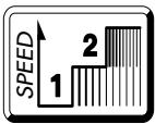
With the On/Off switch 8, two speed steps can be selected.
For hole starting, press the On/Off switch 8 lightly (hole starting step).
For full drilling performance, press in the On/Off switch 8 completely.
ROTATIONAL DIRECTION SWITCHING
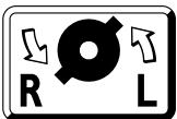
Operate the rotational direction switch 6 only when the machine is at a standstill!
Take hold of the rotational direction switch 6 on both sides.
Right rotation: Set the rotational direction switch 6 to “R”.
Left rotation: Set the rotational direction switch 6 to "L".
Important: Press the rotational direction switch 6 in each case to the stop on the housing, i. e. until it can be felt to engage.
If the rotational direction switch 6 is set between the positions "R" and "L", the machine cannot be switched on.
The tool holder 1 clamps the drilling tools without using a tool key.
Before any work on the machine itself, pull the mains plug!
Clean and lightly grease the tool shaft.
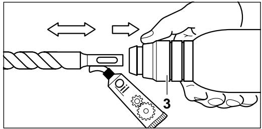
Pull back the unlocking collar 3. Insert the tool while turning into the tool holder until it latches. Release the unlocking collar. Check whether the tool is firmly seated.
Take care that the dust protection cap 2 is not damaged.
Replace damaged dust protection caps!
Slide the unlocking collar 3 to the rear and pull out the tool.


HM 550
English
9
8 Drill Chuck (Accessory)
For drilling work in metal, wood and plastic with drills that have normal shafts, a drill chuck (13 mm max. chuck opening) is available. The drill chuck is mounted on the adapter (accessory) for screwdriver bits. All common drill chucks with 1/2'' x 20 UNF internal threads (13 mm max. chuck opening) can be used.
MOUNTING THE CHUCK
Before any work on the machine itself, pull the mains plug!
Clean the threads of the drill chuck (accessory) and the adapter 13 (accessory). Screw the drill chuck onto the adapter and tighten firmly (approx. 30Nm ). Clamp in a vise for tightening the adapter, for example. Clamp an Allen key in the drill chuck and use it to tighten the chuck. Then lock the adapter in the tool holder the same as a drill.
9 Practical Tips
Do not drill into hidden electrical lines or gas and water pipes. Check the area to be worked with a metal detector, for example, before starting.
For metal, use only flawless, sharpened drills; for stone and concrete, only masonry drills with hard metal inserts.
Always adapt the speed to the material to be worked and the diameter of the drill. For precision working with metal and wood, place the machine in a drill stand (accessory).

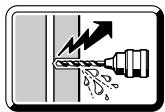
HAMMER- DRILLING
Wear protective glasses and hearing protection.
Do not apply to much pressure. The performance is not increased in this manner.
4 For hammer drilling, work only with protective glasses, hearing protection and the auxiliary handle 12. Check before putting into operation if the shift knob 10 is latched in the position.
DRILLING IN TILES
Start drilling slowly on the tile. After the tile is drilled through, switch to impact drilling.
SCREWDRIVING
Screwdriver bits can be inserted into the adapter 13 (accessory). Commercially available bits with a hexagonal dimension of 6.3mm or 1/4 (DIN 3126, Form C) can be used.
The screwdriver bits are held in the adapter with a spring ring. Therefore, use only bits with a notch.
10 Slip Clutch
If the drilling tool become jammed or get caught, the slip clutch releases.
Remove the load from the machine immediately by pulling back the drilling tool.
Always hold the machine tightly with both hands and assume a secure stance.
11 Maintenance Measures
Before any work on the machine itself, pull the mains plug!
Always keep the ventilation slots clean.
Wipe off the accessible plastic parts regularly with a cloth without cleaning agent.
After heavy use over a long period, the machine should be taken to a Kress service location for an inspection and thorough cleaning.
12 Environmental Protection
Do not dispose of electric tools together with household waste material!
Recycle raw materials instead of disposing as waste.
The machine, accessories and packaging should be sorted for environ
mental friendly recycling.
These instructions are printed on recycled paper manufactured without chlorine.
The plastic components are labelled for categorised recycling.
Subject to change without notice
10 Français
HM 550
Utilisation
PERCAGE - PERCAGE AVEC PERCUSSION
PERCAGE AVEC PERCUSSION
TALADRAR - TALADRAR CON PERCUTOR
GB CE Declaration of conformity We declare under our sole responsibility that this product is in conformity with the following standards or standardization documents: see below
- This electro-tool was manufactured with high precision and subjected to rigorous factory quality controls.
- Therefore, we guarantee the cost-free correction of fabrication or material defects that occur within 36 months of the date of purchase by the end user. We reserve the right to repair defective parts or replace them with new parts. Replaced parts become our property.
- Improper use or handling as well as opening of the machine by unauthorised repair agencies voids the guarantee. Parts subject to wear are excluded from the guarantee.
- The guarantee may only be enforced when defects are reported without undue delay (including shipping damage). Guarantee implementation does not extend the guarantee period.
- If the tool is defective, please complete the guarantee card and return the unit, guarantee card and a brief description of the problem to the responsible service location. Please enclose your sales receipt.
- The guarantee obligations assumed by us shall exclude any further claims on the part of the buyer, in particular the right to recission of a sale, reduction and the assertion of damage claims.
- However, the buyer shall have the right to either a reduction (in the purchase price) or the recession of the sale (cancellation of the sales agreement) should we fail to eliminate any defects within a reasonable period of time.
- Damage claims in accordance with §§ 463, 480 Paragraph 2,635 BGB due to absence of guaranteed quality shall not be not excluded.
- The provisions defined in Items 7 and 8 only apply to the Federal Republic of Germany.
F Garantie
Present Handel bvba/sprl
Industriezone "Wolfstee"
Toekomstlaan 6
B-2200 Herentals
Telephone: +32 - (0)14 - 25 74 74 - Telefax: +32 - (0)14 - 25 74 75
E-mail: info@present.be
France
S.A.R.L. Induba
Westcross Centre, 15 Shield Drive
Brentford TW8 9EX
Phone: +44 (0)208-560 0885 - Telefax: +44 (0)208-847 0790
E-mail: njtoolsbrentford@btopenworld.com
Portugal
Sarraipa S.A.
Garantie-Karte Warranty card
Please fill in immediately and keep in safe place.