
FILTOMATIC CWS - Water filtration system OASE - Free user manual and instructions
Find the device manual for free FILTOMATIC CWS OASE in PDF.

| Product Type | Garden pond water filtration system |
| Brand | OASE |
| Model | FILTOMATIC CWS (available in 3000, 6000, 12000) |
| Use | Mechanical and biological cleaning of garden ponds with or without fish, water temperature +4°C to +35°C |
| Container Material | Plastic (not specified, standard) |
| Power Supply | 230 V ~ 50 Hz (mains socket protected by residual current circuit breaker 30 mA max.) |
| Power Consumption | Not specified (dirty water pump and UVC lamp) |
| UVC Lamp | Integrated UVC pre-clarification, service life ~8000 hours |
| Dirty Water Pump | Integrated, automatic cleaning program with 4 intervals |
| Cleaning Programs | INTERVAL 1 to 4, adapted to water temperature (from 1x/day to 8x/day depending on setting) |
| Display | Water temperature and service hour counter (LED display) |
| Safety Functions | 30 mA residual current circuit breaker, automatic shutdown in case of fault, UV protection |
| Routine Maintenance | Cleaning of filter foams (clogging indicator), manual drainage possible |
| Wear Parts | UVC lamp, quartz glass tube, cleaning rotor, filter foam (references provided) |
| Warranty | 2 years + 1 additional year under conditions (extension card included) |
| Weight | Not specified (variable by model) |
| Dimensions (recommended pit) | Model 3000: ~50x50x30 cm; 6000: ~50x50x50 cm; 12000: ~50x70x50 cm (height) |
Frequently Asked Questions - FILTOMATIC CWS OASE
User questions about FILTOMATIC CWS OASE
0 question about this device. Answer the ones you know or ask your own.
Ask a new question about this device
Download the instructions for your Water filtration system in PDF format for free! Find your manual FILTOMATIC CWS - OASE and take your electronic device back in hand. On this page are published all the documents necessary for the use of your device. FILTOMATIC CWS by OASE.
USER MANUAL FILTOMATIC CWS OASE
Welcome to OASE Living Water. Congratulations on your purchase of the FiltoMatic CWS. Prior to commissioning the unit, please read the instructions of use carefully and fully familiarise yourself with the unit. Ensure that all work with this unit is only carried out in accordance with these instructions.
Adhere to the safety information for the correct and safe use of the unit.
Keep these operating instructions in a safe place! Please also hand over the operating instructions when passing the unit on to a new owner.
Table of Contents
- Scope of delivery 20
- Overview 20
- Legal conditions 20
3.1 Intended use 20
3.2 Use other than that intended 20
3.3 Extended guarantee conditions for the OASE ClearWaterSystem 20
3.4 CE Manufacturer's Declaration 20
- Safety information 21
4.1 Hazards encountered by the combination of water and electricity 21
4.2 Correct electrical installation 21
4.3 Safe operation 21
- Installation 22
- Installation 22
- Start-up 23
- Operation 24
8.1 Controller overview 24
8.2 Setting the dirty water pump 24
8.3 Setting the UVC clarifying unit 25
- Maintenance and cleaning 26
9.1 Cleaning foam filters 26
9.2 Remove and separate the cleaning components from each other 26
9.3 Cleaning the dirty water pump (Figure N) 27
9.4 Changing the UVC lamp in the UVC clarifying unit 27
9.5 Checking the cleaning rotor 28
9.6 Changing the foam filters 28
9.7 Thorough cleaning of the unit 28
-
Storage/Over-wintering 29
-
Remedy of faults 30
- Wear parts 30
- Disposal 30
Technical data 79
Symbols on the unit 80
81
1. Scope of delivery
- Open the lid (1) using the rotary handle (2) to remove the assembly components (Figure A).
| Figure B | Number | Description |
| 3 | 1 | Container FiltoMatic CWS |
| 4 | 1 | Outlet DN70 |
| 5 | 1 | Flat sealing DN70 |
| 6 | 1 | Flat sealing 1 1/2" |
| 7 | 1 | O ring DN40 |
| 8 | 1 | Outlet sheath DN40 |
| 9 | 1 | Inlet sheath 1 1/2" |
| 10 | 2 | Union nut |
| 11 | 1 | Hose clip |
| 1 | Instructions for use | |
| 1 | Fast assembly instruction manual | |
| 1 | Product DVD | |
| 1 | Guarantee brochure | |
| 1 | Clear water guarantee card | |
| 1 | Guarantee extension card 2+1 |
2. Overview
| Figure C | Designation | For a description, please refer to Chapter ... |
| 3 | Container | Assembly, cleaning and maintenance |
| 4 | Outlet DN70 | Installation |
| 8 | Dirty water outlet DN40 | Installation |
| 9 | Inlet 1 1/2" | Installation |
| 12 | Soiling indicator | Maintenance and cleaning |
| 13 | Foam holder | Maintenance and cleaning |
| 14 | Dirty water pump | Maintenance and cleaning |
| 15 | Controller | Operation |
| 16 | UVC clarifying unit | Maintenance and cleaning |
| 17 | Stop valve for inlet | Starting up, cleaning and maintenance |
| 18 | UVC lamp control window | Maintenance and cleaning |
| 19 | Engagement hooks | Maintenance and cleaning |
| 20 | Biokick CWS infill opening | Start-up |
3. Legal conditions
3.1 Intended use
The FiltoMatic CWS is intended as a filter system for the mechanical and biological cleaning of garden ponds having a water temperature of between +4^ and +35^ . The unit is exclusively suited for private use and may only be employed for cleaning garden ponds with or without fish population.
3.2 Use other than that intended
Danger to persons can emanate from this unit if it is not used in accordance with the intended use and in the case of misuse. If used for purposes other than that intended, our warranty and operating permit will become null and void.
3.3 Extended guarantee conditions for the OASE ClearWaterSystem
Guarantee claims can only be brought forward to us, OASE GmbH, Tecklenburger Straße 161 in D-48477 Hörstel, by returning to us the unit or part of the unit subject to complaint, freight free, at your own risk, accompanied by the original purchase receipt from the OASE specialist dealer, this guarantee document and written information of the fault encountered. Should the dirty water pump, UVC clarifying unit or controller be defective, only return the individual defective component (dirty water pump, UVC clarifying unit, controller), not the complete unit.
3.4 CE Manufacturer's Declaration
We declare conformity in the sense of the EC directive, EMC directive (2004/108/EC) as well as the low voltage directive (2006/95/EC). The following harmonised standards apply:
EN 60335-1, EN 60335-41, EN 55014-1, EN 55014-2, EN 55015, EN 61000-3-2, EN 61000-3-3
Signature:

4. Safety information
The company OASE has built this unit according to the state of the art and the valid safety regulations. Despite the above, hazards for persons and assets can emanate from this unit if it is used in an improper manner or not in accordance with its intended use, or if the safety instructions are ignored.
For safety reasons, children and young persons under 16 years of age as well as persons who cannot recognise possible danger or who are not familiar with these operating instructions, are not permitted to use the unit.
4.1 Hazards encountered by the combination of water and electricity
The combination of water and electricity can lead to death or severe injury from electrocution, if the unit is incorrectly connected or misused.
Prior to reaching into the water, always disconnect the power supply to all units used in the water.
4.2 Correct electrical installation
For your own safety, consult a qualified electrician when you have questions or encounter problems.
- Electrical installations at garden ponds must meet the international and national regulations valid for installers. Especially adhere to DIN VDE 0100 and DIN VDE 0702.
- Compare the electrical data of the power supply with those indicated on the type plate on the UVC clarifying unit.
Only operate the FiltoMatic CWS when plugged into a correctly fitted socket.
- Please note that the power supply must be fused via a fault current protection system with a maximum reference fault current of 30mA .
Install the FiltoMatic CWS such that any risk of injury to persons is excluded.
Only use cables that are uncoiled.
Extension cables must be approved for outdoor use and meet DIN VDE 0620 standards.
- Route the connection cable so that damage is excluded.
- Keep all connection points dry. Risk of electrocution.
4.3 Safe operation
Only operate the FiltoMatic CWS if no persons are in the water.
- Never carry or pull the UVC clarifying unit and the dirty water pump of the FiltoMatic CWS by holding on the connection cables.
- Do not operate defective units. Do not operate the FiltoMatic CWS if the electrical connection cables are defective. Pull the power plug immediately. The connection cables of the UVC clarifying unit and of the dirty water pump cannot be repaired. Replace the components. Dispose of the defective components in compliance with the environmental regulations.
- Never open the housing of the UVC clarifying unit, dirty water pump, control system or their attendant components, unless this is explicitly mentioned in these instructions of use.
Only use original spare parts and accessories.
Never use the system for filtering fluids other than water.
The radiation of the UVC lamp, even in small doses, is dangerous for eyes and skin. Never operate the UVC lamp in a defective housing or outside of the housing.
- Never operate the UVC lamp without cleaning rotor, as this also acts as an eye protection against UVC radiation.
Overvoltage in the mains could lead to operating malfunctions of the unit. For information, please refer to chapter "Remedy of faults".
5. Installation
We recommend to thoroughly clean the garden pond to ensure almost maintenance-free operation of the FiltoMatic CWS from the very beginning. OASE's recommendation for this cleaning work is the use of the pond sludge suction unit Pondovac. In general, cleaning work can be omitted when the FiltoMatic CWS is used in a newly installed garden pond.
Installing the FiltoMatic CWS (Figure D,E)
Plan the installation of the FiltoMatic CWS. Careful planning and taking the environmental conditions into account will lead to optimum operating conditions for the FiltoMatic CWS. The following points can help you with your planning.
A water course guarantees optimum water return from the FiltoMatic CWS to the garden pond. In this manner, the filtered pond water is enriched with oxygen prior to returning to the pond. Should the local situation not allow the installation of a water course, extend the outlet using a DN70 pipe for the filtered water to return to the pond via the pipe. Please refer to the Installation chapter for the installation of a DN70 pipe.
Horizontal alignment of the FiltoMatic CWS is crucial to prevent drainage of the pond in the event of an overflow. Carry out the alignment using a spirit level.
Take the large volume of the FiltoMatic CWS as well as the resulting weight when filled into account. Select a suitable ground or a bottom slab in the pit to prevent the FiltoMatic CWS from sagging.
Plan sufficient space for movement to be able to carry out cleaning and maintenance work.
- Dig a suitably dimensioned pit for the installation of FiltoMatic CWS (Figure D). Take into consideration that the FiltoMatic CWS can be buried up to the top recess (Figure E, height c). Please use the following table as a basis for the pit dimensions:
| Model | a | b | c (+ bottom slab height) |
| Filtomatic 3000 CWS | approx. 50 cm | approx. 50 cm | approx. 30 cm |
| Filtomatic 6000 CWS | approx. 50 cm | approx. 50 cm | approx. 50 cm |
| Filtomatic 12000 CWS | approx. 50 cm | approx. 70 cm | approx. 50 cm |
Fill the container (3) with water prior to backfilling the soil to avoid compressing the container.
- Route the DN40 pipe end for the dirty water outlet at a distance from the pond that prevents the pumped out dirty water from flowing back into the pond.
6. Installation
Installation of the FiltoMatic CWS
The FiltoMatic CWS is delivered pre-assembled. Assembly is reduced to the outlet and the inlet and dirty water outlet connections.

The outlet sheath (8) for the dirty water outlet is transparent. In this manner, the degree of soiling of the outflowing water is visible during future cleaning. Pumping can be stopped as soon as visibly clean water flows out of the dirt outlet. Cleaning is then completed.
Installation of the outlet (Figure F)
- Place the flat sealing (5) over the outlet screw (25) pre-fitted on the housing.
- Screw the outlet (4) on the outlet screw (25).
- If necessary, connect a DN70 pipe (26) to the outlet (4) as an extension to allow the filtered pond water to return into the pond. Ensure a minimum incline of 1.5% for the DN70 pipe.
As an extension for the outlet, OASE recommends the following:
- DN70 pipe, 480 mm, black (OASE Order No. 55034)
- DN70 pipe elbow, 45^ , black (OASE Order No. 55044)
- DN70 pipe elbow, 87^ , black (OASE Order No. 55045)
- DN70 pipe elbow, T, black (OASE Order No. 55046)
Installation of the inlet (Figure F)
- Plug the inlet sheath (9) and the flat sealing (6) into the union nut (10) and tighten at the stop valve thread (21).
- Slide the hose clip (11) over the hose (24) arriving from the Aquamax. Push the hose on the inlet sheath (9) and fasten with the hose clip.
Hose recommended by OASE: Spiral hose, green (OASE Order No. 52981)

Prior to the assembly, place the hose end in hot water for two minutes. It will then be easier to slide the hose onto the inlet sheath (9).
Installation of the dirty water outlet (Figure F)
- Fit the O ring (7) on the outlet sheath (8) and into the union nut (10). Then tighten to the thread of the pre-assembled dirty water outlet (22).
- Plug a DN40 pipe (23) onto the outlet sheath (8). Route the end of the DN40 pipe to a point where the dirty water to be pumped out can trickle into the ground. Ensure a gravity of 1.5% to 2% for the DN40 pipe.
As an extension for the dirty water outlet, OASE recommends the following:
- DN40 pipe, 480 mm, black (OASE Order No. 50307)
- DN40 pipe elbow, 45^ ,black (OASE Order No. 50308)
7. Start-up

Attention! Dangerous electrical voltage.
Possible consequences: Death or severe injury.
Protective measures: Disconnect the power plug (Figure G) prior to reaching into the water and commencing work.
Follow the safety information!
The FiltoMatic CWS switches on automatically when the power connection is established.
Switching on (Fig. G): Plug the power plug (27) into the socket.
Switching off (Fig. G): Disconnect the power plug (27).
Fill the container with water (Figure C)
- Switch the Aquamax pump on prior to commissioning the FiltoMatic CWS. Container (3) has to be filled with water.

Stop valve (17) needs to be open to enable the container to be filled. For this purpose, press the stop valve (17) down against the stop.
As soon as the water level in the container (3) reaches the outlet (4), the filtered pond water returns into the pond via the outlet (4).
For further settings of the FiltoMatic CWS, please read the following Chapter Operation.
Filling with biological filter starter (Figure C)
We recommend the OASE filter starter Biokick CWS (OASE Order No. 50295) for a fast growth of bacteria populations. Micro-organisms colonise the filter system, multiply and ensure an enhanced quality of the pond water by the decomposition of excess nutrients.
Fill the quantity of Biokick CWS sufficient for the volume of your pond into the infill opening (20).
8. Operation
8.1 Controller overview
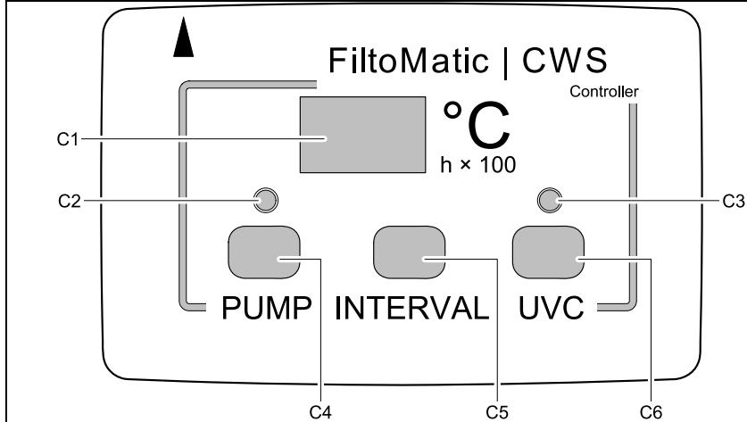
C1 Display
C2 LED displaying the dirty water pump function
C3 LED displaying the UVC function
C4 Key for manual dirty water pump operation
C5 Key for setting a cleaning program for the dirty water pump
C6 Key for setting an operating program for the UVC clarifying unit
Displays on the controller
Display (C1)
Water temperature as standard
- Cleaning program as selected
-SAVED settings
- Operating hour counter (h× 100)
- switches automatically back to temperature display 2 seconds after the last key actuation
LED for dirty water pump (C2)
- LED flashes green: Partial container drainage
- LED is lit green: complete container drainage
- LED is lit red: Pump blocked
- LED off: Pump not active
LED for UVC clarifying unit (C3)
- LED is lit blue: UVC clarifying unit is switched on
- LED flashes blue in a 8 second interval: The UVC clarifying unit is integrated in the Automatic (AU) operating program
LED flashes in a 1 second interval: The UVC lamp was active for 7500 operating hours; remaining operating life: 500 operating hours - LED flashes twice each half second and once for one second: UVC lamp has reached 8000 operating hours
- LED off: UVC clarifying unit is switched off
Note:
The integrated thermometer permanently measures the water temperature, thereby forming the reference value for the operating programs.
The silicone cover protects the controller from soiling; it impairs neither the display reading nor the functionality of the keys. The controller is water tight and can also be operated without the silicone cover.

Moisture can collect in the transparent gap of the controller. This moisture is negligible and does not affect the controller function.
8.2 Setting the dirty water pump
As the water temperature, the degree of soiling of the pond water greatly depends on the fish population. The dirty water pump pumps out the dirt from the container bottom in intervals. The four different cleaning programs allow to individually adapt the interval for pumping off the dirty water to the degree of soiling. A cleaning cycle takes approx. 8 seconds. Approx. 5 litres of pond water are required for one cleaning cycle. The table shows the cleaning program selection options. The cleaning program INTERVAL 1 includes the majority of cleaning intervals, INTERVAL 4 the smallest number of intervals. Select a program that is best suited for the degree of soiling of the pond water. When delivered, cleaning program INTERVAL 2 is set as a default.
| Water temperature | Cleaning programs, dirty water pump + Intervals - Intervals | ||||
| INTERVAL 1 | INTERVAL 2 | INTERVAL 3 | INTERVAL 4 | OF | |
| <5 °C | off | off | off | off | off |
| <8 °C | 1 × per day | every 2 days | every 3 days | every 3 days | off |
| 8 °C - 14 °C | 2 × per day | 1 × per day | every 2 days | every 3 days | off |
| 15 °C - 21 °C | 4 × per day | 2 × per day | 1 × per day | every 2 days | off |
| ≥22 °C | 8 × per day | 4 × per day | 2 × per day | 1 × per day | off |

The cleaning programs are inactive at a water temperature of < 5^ . The pump can then only be actuated manually. For fully pumping out, keep the PUMP (C4) key permanently pressed.
Setting the cleaning program for the dirty water pump
- Press the INTERVAL (C5) key. The cleaning program INTERVAL 2 appears in the display (C1).
- Press the INTERVAL (C5) key until the desired cleaning program appears.
-
Release the INTERVAL (C5) key when the desired cleaning program is displayed.
-
The setting is saved when the water temperature appears in the display (C1) after a period of approx. 2 seconds.
Manual pumping out of the dirty water
The dirty water can also be removed by pumping manually.
Press the PUMP (C4) key
- The LED (C2) flashes green. Soiling removal starts immediately.

Complete container emptying starts when you keep the PUMP (C4) key pressed for longer than 10 seconds. The green LED (C2) is lit. The dirty water pump runs for a maximum of 4 minutes. You can stop the drainage cycle by pressing the PUMP (C4) key once.
8.3 Setting the UVC clarifying unit
The degree of soiling of the pond water by the formation of algae is notably determined by the water temperature. With its UV light, the UVC clarifying unit operating under water removes green algae, as such forming a significant component for pond water cleaning. Depending on the water temperature, the UVC lamp of the UVC clarifying unit is switched on and off in intervals with the AU operating program. In this manner it can be individually adapted to the degree of soiling. The following table shows the operating program AU (Automatic) of the UVC clarifying unit as well as the operating statuses ON and OFF.
| Water temperature | UVC clarifying unit operating programs | |||
| AU | ON | OFF | ||
| UVC lamp is switched on | UVC lamp is switched off | UVC lamp is permanently switched on | UVC lamp is permanently switched off | |
| < 8 °C | 8 h | 16 h | ||
| 8 °C - 14 °C | 48 h | 24 h | ||
| 15 °C - 21 °C | 72 h | 24 h | ||
| ≥ 22 °C | 96 h | 24 h | ||

When delivered, the operating program AU is set as a default.
- With Power ON, the operating program AU starts with the OFF interval. The UVC lamp does not light up. The use of Biokick CWS during start-up protects the bacteria cultures in the Biokick CWS.
The UVC clarifying unit starts with the ON interval when the AU operating program is manually selected.
Setting the operating program for the UVC clarifying unit
- Press the UVC (C6) key. The AU operating program appears on the display (C1).
- Press the UVC (C6) key until the desired operating program is displayed.
-
Release the UVC (C6) key when the desired operating program is displayed.
-
The setting is saved when the water temperature appears in the display (C1) after a period of approx. 2 seconds.
Inquiry of the operating hour counter reading of the UVC clarifying unit
The operating life of a UVC lamp for the UVC clarifying unit is approx. 8000 hours. The integrated operating hour counter counts down from this value.
-
Keep the UVC (C6) key pressed for 5 seconds. A number appears in the display (C1).
-
Multiply this number by 100 to calculate the remaining number of operating hours.
Example: displayed value 45 × 100 = 4500 remaining operating hours.
Resetting the operating hour counter reading of the UVC clarifying unit
Reset the operating hour counter after changing a UVC lamp.
-
Keep the UVC (C6) key pressed for 12 seconds!
-
The remaining operating life appears on the display (C1) after 5 seconds. Following this, the display flashes. The operating hour counter is reset to 8000 hours, when the water temperature appears in the display (C1).
-
Release the UVC (C6) key.
9. Maintenance and cleaning

Attention! Dangerous electrical voltage.
Possible consequences: Death or severe injury.
Protective measures: Disconnect the power plugs of all the units in the water prior to reaching into the water and commencing work.
9.1 Cleaning foam filters
Cleaning intervals depend on the degree of soiling of the foam filters. A higher water level in the soiling indicator (Figure C, 12) in the inner cover signals that the foam filter cleaning capacity has decreased. Cleaning is due from a degree of soiling of 75% or in the event of an overflow at the latest.
- Open lid (1) with the rotary handle (2) and remove lid from the container (3) (Figure H).
-
Close stop valve (17) by pulling it up (Figure I).
-
Pond water no longer flows into the container.
Note: Water will spurt out of the air intake socket when closing the stop valve (17). -
Pull up the foam holder (13) three times (Figure J).
- The foam filters will be compressed. The soiling will be washed out.
- Press the PUMP key (C4) on the controller (15) for longer than 10 seconds (Figure J).
- The LED (C2) is lit green. All of the dirty water in the container will be pumped out.
- Open the stop valve (17) by pressing it down.
- The container fills up with pond water again.

Repeat the cleaning cycle if the foam filters are heavily soiled.
9.2 Remove and separate the cleaning components from each other
For cleaning and maintenance of the cleaning components of the dirty water pump (14) and the UVC clarifying unit (16) it is necessary to take both out of the container. The controller (15) is fitted to the UVC clarifying unit. The cleaning components are not permanently connected to the inner cover (47) but rest in the guides of the inner cover (47) or of the stop valve (17) respectively.
This is how to remove the cleaning components (Figure K)
- Open lid (1) with the rotary handle (2) and remove lid from the container (3) (Figure H).
-
Close the stop valve (17) by pulling it up.
-
Pond water no longer flows into the container.
-
Note: Water will spurt out of the air intake socket when closing the stop valve.
-
Lift the cleaning components of the dirty water pump (14) and of the UVC clarifying unit (16) out of the inner cover (47) as one unit.
This is now the cleaning components and the controller are separated from one another (Figure L)
- Keep the engagement hook (30) on the UVC clarifying unit (16) pressed.
- Remove the controller (15) from the UVC clarifying unit by applying force.
- Pull the connection cable (28) of the dirty water pump off the controller (15) by applying force.
- Plug in the silicone caps to protect the open sockets.
-
Reassemble the cleaning components and the controller in the reverse order (Figure M).
-
When assembling the controller and the UVC clarifying unit, ensure that the arrows on both components point to one another.

During assembly, check the seating of the O rings (29) at the connection points of the controller and of the UVC clarifying unit! Clean the O rings (29) as required. The electrical contacts will corrode if the O rings are missing or incorrectly seated. This will lead to irreparable damage to the components!
9.3 Cleaning the dirty water pump (Figure N)
Cleaning of the dirty water pump becomes due when the rotor of the pump motor (33) is blocked. This can happen as a result of larger soiling, such as, e.g. stones. The LED indicator (C2) on the controller (15) is lit red when the dirty water pump is blocked.
- Turn the motor housing (33) until the symbol showing "Lock open" points to the arrow at the top pipe (31).
- Remove and clean the motor housing (33).
-
Reassemble in the reverse order.
-
Important: The motor housing (33) is only arrested when the "Lock closed" symbol points on the arrow on the top pipe (31) (Figure N).
-
Press the PUMP button (C4) once.
- The LED (C2) changes from red to green. The dirty water pump (14) starts up. Otherwise, the dirty water pump (14) will not start up because of a malfunction. In this context, please refer to Chapter Remedy of faults.
- If necessary, clean the overflow on the top pipe (31). To this effect, open the soiling pipe cover (32).
9.4 Changing the UVC lamp in the UVC clarifying unit

Attention! Dangerous ultra-violet radiation.
Possible consequences: Severe injury to the eyes and the skin.
Protective measures: Only switch the unit on with the housing fitted.

The controller (15) does not show when the UVC lamp is defective. Check the function of the UVC lamp by looking into the control window (18) at regular intervals (Figure O).
The operating life of the UVC lamp being limited, it has to be replaced once its useful life has elapsed (please also refer to Chapter Checking the reading of the UVC clarifying unit operating counter).
- Turn the water housing (35) until the symbol showing "Lock open" points to the arrow at the UVC top pipe (34) (Figure O).
- Pull off the water housing (35) (Figure O).
- Remove the cleaning rotor (37) from the quartz glass tube (45) (Figure P).
- Loosen the screw (40) from the union nut (39), then unscrew the union nut (39) (Figure Q).
- Pull off the quartz glass tube (45) including the O ring (46) by a rotary movement (Figure R).
- Pull off the UVC lamp protection (44) (Figure R).
- Pull the UVC lamp (43) out of its position in the UVC top section (34) and replace (Figure R).
-
Reassemble the UVC clarifying unit in the reverse order.
-
Important: The water housing (35) is only closed when the "Lock closed" symbol points to the arrow on the UVC top section (34) (Figure O).

- During assembly ensure that the stop (41) of the union nut (39) butts against the stop (42) on the UVC top section (34). Only then can the screw (40) be turned in (Figure Q).
The O ring (36) on the water housing closure (35) is firmly clamped on. Only remove the O ring (36) if it needs replacing, e.g. has become brittle (Figure O). - Condensate forms in the quartz glass tube (45). This condensate cannot be avoided, however, it does not impair function and safety.
The quartz glass tube (45) can become scratched or blind over time. In this case, sufficient cleaning performance of the UVC lamp (43) is no longer guaranteed. The quartz glass tube (45) must be replaced.
9.5 Checking the cleaning rotor
The cleaning rotor (37) cleans the quartz glass tube (45). The rotor is driven by the water flow in the water housing (Figure P).
The constant rotational movement of the cleaning rotor (37) causes wear of the bearing bush (38). In this case, the cleaning rotor (37) needs replacing (Figure P).
- Turn the water housing (35) until the symbol showing "Lock open" points to the arrow at the UVC top pipe (34) (Figure O).
- Pull off the water housing (35) (Figure O).
-
Check the wearing condition of the bearing bush (38).
-
When the bearing bush (38) has worn down to 0mm , the cleaning rotor (37) needs to be replaced (Figure P).
-
Reassemble the UVC clarifying unit in the reverse order.
- Important: The water housing (35) is only closed when the "Lock closed" symbol points to the arrow on the UVC top section (34) (Figure O).
9.6 Changing the foam filters
We recommend to change the foam filters (49) once a year, or whenever a gap forms between the foam filter (49) and the inner cover (47).
How to change the foam filters:
- Open lid (1) with the rotary handle (2) and remove lid from the container (3) (Figure H).
-
Close stop valve (17) by pulling it up (Figure S).
-
Pond water no longer flows into the container.
Note: Water will spurt out of the air intake socket when closing the stop valve (17). -
Pull up the foam holder (13) in the inner cover (47) three times. The water in the foam filters (49) is pressed out (Figure I).
-
Press the PUMP key (C4) on the controller (15) for longer than 10 seconds (Figure J).
-
The LED (C2) is lit green. The dirty water in the container will be pumped out.
-
Lift the cleaning components of the dirty water pump (14) and of the UVC clarifying unit (16) out of the inner cover (47)(Figure K).
- Release the blue engagement hooks (19) on both sides, then remove the inner cover (47) including the foam holders (13) out of the container (Figure S).
- Slightly lift the foam holder (13) by pulling, press in the blue engagement hooks (48) at the foam holders (13), then take out the foam holders (13) downward (Figure T).
- Pull the used foam filters (49) over the handle of the foam holder (12) by pulling and insert new foam filters (49) in the opposite order (Figure U).
- Insert the foam filters in the reverse order.
9.7 Thorough cleaning of the unit
Light-weight suspended matter is mechanically filtered by the foam filters and, if necessary, biologically broken down. Suspended matter heavier than water will sediment out and soil the container bottom. Thoroughly clean the unit once per year, preferably when you prepare the FiltoMatic CWS for the winter.
Fully drain the container
Full drainage takes a maximum of 4 minutes.
- Switch off the Aquamax pump.
- Open lid (1) with the rotary handle (2) and remove lid from the container (3) (Figure H).
-
Pull up the foam holder (13) three times (Figure J).
-
The foam filters will be compressed. The soiling will be washed out.
-
Press the PUMP (C4) key for longer than 10 seconds.
-
The LED (C2) is lit green. The container is emptied.
- You can stop the drainage cycle by pressing the PUMP (C4) key once. Once the container is fully drained, when the dirty water pump switches off no water flows through the transparent outlet sheath (6).
Cleaning the unit
For this purpose, remove the lamella separator (51) and the dirt pyramid (52). To this effect, completely empty the container and remove the inner cover (47). Please refer to the chapters above.
How to remove and clean the lamella separator
- Press down the engagement hook (50) and pull the lamella separator (51) upward and out of the the guide on the container (3) (Figure V).
- Press in the engagement hook (52) at the lamella separator top (51) and fold out both sections of the lamella separator (51) (Figure W).
- Clean both parts using clean water and a soft brush.
- Reassemble the lamella separator (51) in the reverse order
-
Insert the lamella separator (51) in the container (3) (Figure X).
-
Ensure that the engagement hook (50) engages at the stop valve (17).
How to remove and clean the dirt pyramid (Figure X)
Only remove the dirt pyramid (53) if necessary. A great deal of force is required for disassembly and re-assembly.
- Reach beneath the dirt pyramid (53) and detach the pyramid from the three holders at the container bottom by vigorously pulling up.
- Clean the dirt pyramid (53) using water and a soft brush.
- Wash out the container bottom.
-
Plug the dirt pyramid (53) onto the holders by applying a large amount of pressure.
-
The engagement in the holders is audible by a click.

An approx. 8 mm spacing is provided between the dirt pyramid (53) and the container bottom. This gap allows the dirty water pump to pump off the dirt gathered at the container bottom. Take this spacing into account during assembly. Do not attempt to press the dirt pyramid (53) fully down to the container bottom by applying excessive force!
10. Storage/Over-wintering
Prior to the period of frost starting, store the cleaning units dirty water pump (14), controller (15) and UVC clarifying unit (16) in a frost-free place.
-
Thoroughly clean all components (see chapter Carry out complete cleaning) and check all components for damage.
-
The container (3) and the foam filters (49) need not be stored frost-free. However, completely empty the container (3) prior to storing using the pump.
-
Cover the container (3) to prevent the ingress of water.
-
The lid (1) being closed is not sufficient, as water can enter the container through the recess provided for the controller.
OASE recommends the following cover:
- FiltoMatic Cap, size L, for FiltoMatic 3000 CWS and 6000 CWS (OASE Order No. 50268)
- FiltoMatic Cap, size XL, for FiltoMatic 12000 CWS (OASE Order No. 50269)
11. Remedy of faults
| Malfunction | Cause | Remedy |
| The controller does not switch on | No mains voltage | Check mains voltage Check supply lines |
| Controller incorrectly positioned on the UVC clarifying unit | Check the controller seating | |
| Water from the DN70 outlet does not return to the pond | Aquamax pump not switched on | Switch on Aquamax pump |
| Stop valve closed with the lid open | Open stop valve | |
| Dirty water pump does not switch on | Pump rotor blocked | Clean pump rotor |
| Temperature < 5 °C | Unit cannot be operated | |
| Container already empty | Fill container | |
| Container partly emptied, dirty water pump cannot prime | Fill container | |
| UVC lamp does not switch on | UVC lamp defective | Changing the UVC lamp |
| The safety system in the UVC clarifying unit has tripped as a result of overvoltage in the mains | Switch of the rated voltage and on again to reset the safety system - Check that the UVC lamp is lit in the control window (blue light) - To test, we suggest to switch on the UVC lamp using the UVC key (operating status ON) |
12. Wear parts
| Wear part | Model | Ident No. |
| UVC lamp | FiltoMatic 3000 CWS | 56112 |
| FiltoMatic 6000 CWS | 56236 | |
| FiltoMatic 12000 CWS | 56237 | |
| Quartz glass tube | FiltoMatic 3000 CWS | 22622 |
| FiltoMatic 6000 CWS | 29419 | |
| FiltoMatic 12000 CWS | 11440 | |
| Cleaning rotor | FiltoMatic 3000 CWS | 12703 |
| FiltoMatic 6000 CWS | 12704 | |
| FiltoMatic 12000 CWS | 12705 | |
| Foam filter | FiltoMatic 3000/6000/12000 CWS | 50314 |
13. Disposal
Dispose of the unit in accordance with the national legal regulations.
Préface
- Table of Contents
- Scope of delivery
- Overview
- Legal conditions
- Intended use
- Use other than that intended
- Extended guarantee conditions for the OASE ClearWaterSystem
- CE Manufacturer's Declaration
- Safety information
- Hazards encountered by the combination of water and electricity
- Correct electrical installation
- Safe operation
- Installation
- Installing the FiltoMatic CWS (Figure D,E)
- Installation
- Installation of the FiltoMatic CWS
- Installation of the outlet (Figure F)
- Installation of the inlet (Figure F)
- Installation of the dirty water outlet (Figure F)
- Start-up
- Fill the container with water (Figure C)
- Filling with biological filter starter (Figure C)
- Operation
- Controller overview
- Setting the dirty water pump
- Setting the cleaning program for the dirty water pump
- Manual pumping out of the dirty water
- Setting the UVC clarifying unit
- Setting the operating program for the UVC clarifying unit
- Inquiry of the operating hour counter reading of the UVC clarifying unit
- Resetting the operating hour counter reading of the UVC clarifying unit
- Maintenance and cleaning
- Cleaning foam filters
- Remove and separate the cleaning components from each other
- This is how to remove the cleaning components (Figure K)
- This is now the cleaning components and the controller are separated from one another (Figure L)
- Cleaning the dirty water pump (Figure N)
- Changing the UVC lamp in the UVC clarifying unit
- Checking the cleaning rotor
- Changing the foam filters
- How to change the foam filters:
- Thorough cleaning of the unit
- Fully drain the container
- Cleaning the unit
- How to remove and clean the lamella separator
- How to remove and clean the dirt pyramid (Figure X)
- Storage/Over-wintering
- Remedy of faults
- Wear parts
- Disposal
- Préface
Brand : OASE
Model : FILTOMATIC CWS
Category : Water filtration system