USER MANUAL F 600 JOTUL
Safety notice: If this solid fuel room heater is not properly installed, a house fire may result. For your safety, follow the installation directions. Contact local building or fire officials about restrictions and installation inspection requirements in your area. Kindly save these instructions for future reference.
Tested and listed by ITS, Intertek Testing Services, Middleton, Wisconsin.
Tested to U.S. Standards: ANSI/UL 1482 & 737, Canadian Standards: CAN/ULC-S627-M93

Standards:
The Jøtul F 600 woodstove has been tested and listed to; U.S. Standards: ANSI/UL 737 and ANSI/UL 1482. Canadian Standards: CAN/ULC-S627-M93
Tests performed by:
ITS Intertek Testing Services, Middleton, WI
Manufactured by:
Jøtul AS, P.O. Box 1411, N-1602 Fredrikstad, Norway
Distributed by:
Jøtul North America, 55 Hutcherson Drive, Gorham, Maine 04038, USA
This heater meets the U.S. Environment Protection Agency's Emissions limits for wood heaters manufactured and sold after July 1, 1990.
Under specific test conditions, this heater has shown heat output at rates ranging from 13,500 to 45,900 BTU's per hour.
The Jøtul F 600 woodstove is only listed to burn wood. Do not burn any other fuels.
Jotul North America Inc.
55 Hutcherson Drive
Gorham, Maine o4o38
USA
When installing, operating and maintaining your Jøtul F 600 woodstove, follow the guidelines presented in these instructions, and make them available to anyone using or servicing the stove.
A number of areas require a building permit to install a solid fuel burning appliance.
In the U.S., the National Fire Protection Association's Code, NFPA 211, Standards for Chimneys, Fireplaces, Vents and Solid Fuel Burning Appliances, or similar regulations, may apply to the installation of a solid fuel burning appliance in your area.
In Canada, the guideline is established by the CSA Standard, CAN/CSA-B365-M93, Installation Code for Solid-Fuel-Burning Appliances and Equipment.
Always consult your local building inspector or authority having jurisdiction to determine what regulations apply in your area.
NATIONAL FIREPLACE INSTITUTE
CERTIFIED
www.nficertified.org
We suggest that our woodburning hearth products be installed and serviced by professionals who are certified in the U.S. by the National Fireplace Institute® (NFI) as NFI Woodburning Specialists or who are
certified in Canada by Wood Energy Technical Training (WETT).

Wood Energy Technical Training
ww . w e t t i n c . c a
Table of Contents:
Standards. 2
Safety Notices 3
Installation 4
Assembly before Installation. 4
Chimneys 4
Masonry Chimneys 5
Prefabricated Chimneys. 5
Chimney Height. 5
Wall Pass-throughs. 5
Connecting to the Chimney............6
Masonry Chimney Thimbles. 6
Hearthmount into a Masonry fireplace. 6
Prefabricated Chimneys. 6
Clearances to combustibles. 7
Floor Protection 7
Clearances to Walls and Ceilings. 7
Using Shields to reduce Clearances. 7
Alcove Installation 8
Mobile Home Installation 8
Operation.. 8
Controls on The Jøtul F 600. 8
Breaking in your new Stove 8
Starting and Maintaining a Fire 9
Adding Fuel. 9
The Formation of Creosote 9
Maintenance 10
Glass Care. 10
General Maintenance 11
Gaskets. 11
Accessories 11
Firescreen 11
Outside Air Kit 11
Floor Bracket Kit. 12
Rear Heatshield 12
Bottom Heatshield. 12
Stove -Top Thermometer 12
Side Door Lock Kit. 12
Figures 13-14
Clearance Chart and Diagrams. 16-17
Parts Diagram 18
Appendix A (alternate floor protection) … 19
Save these instructions and make them available to anyone using or servicing the stove.
Safety notices:
- Be sure to read this entire manual before you install or use your new Jøtul F 600 woodstove.
- If this room heater is not properly installed, a house fire may result. To reduce the risk of fire, follow the installation instructions. Failure to follow these instructions may result in property damage, bodily injury, or even death.
- Jøtul recommends that you have your new Jøtul F 600 installed by a professional installer of solid fuel burning appliances.
- Extremely hot while in operation! Keep children, clothing and furniture away. Contact may cause skin burns.
- Avoid creating a low pressure condition in the room where the stove is operating. Operating an exhaust fan or a clothes dryer could create a low pressure area, causing poisonous gases to come out of the stove into the room.
- You can prevent low pressure conditions by providing adequate combustion air within 24" but not closer than 12" from the stove. Or, simply install the optional outside air manifold system, which allows the direct connection of air from outside the house to the stove.
- Do not use chemicals or fluids to start the fire. Some fuels will, during combustion, separate carbon monoxide and generate it in the burn chamber. Carbon monoxide is toxic, so please follow the guidelines in this manual for proper operation of your Jøtul F 600.
- If you for some reason experience smoke "roll-out" from the stove, it may activate smoke detectors if installed in the house.
USA/CANADA
Installation:
If this solid fuel room heater is not properly installed a house fire may result. For your safety, follow the installation directions. Contact the local building or fire officials about restrictions and installation inspection requirements in your area.
Reminder:
Your local officials have final authority in determining if a proposed installation is acceptable. Any requirement, that is requested by the local authority having jurisdiction, that is not specifically addressed in this manual, defaults to NFPA 211, and local codes in the U.S. or in Canada, CAN/ CSA-B365-M and local codes.
Assembly before installation
The Jøtul F 600 is shipped with the flue collar, gasketing and hardware inside the stove.
- To install the flue collar in the top or rear exit position remove the tape from the gasketing and adhere to the groove on the back of the stove around the flue opening.
- Place the flue collar on the stove in the top or rear exit position and secure with the nut, bolt and washer.
- The nut and washer are placed on the inside of the stove.
Chimney connector
The chimney connector is a single walled pipe used to connect the stove to the chimney. For use with the Jøtul F 600, the chimney connector must be 6'' in diameter, with a minimum thickness of 24 gauge black steel.
- Aluminum and Galvanized steel pipe is not acceptable for use with the Jøtul F 600. These materials cannot withstand the extreme temperatures of a wood fire and can give off toxic fumes when heated.
- Do not use the connector pipe as a chimney.
Each chimney connector or stove pipe section must be installed to the stove flue collar and to each other with the male (crimped) end toward the stove. See figure 2, page 13.
- This prevents any amount of condensed or liquid creosote from running down the outside of the pipe or the stove top.
- All joints, including the flue collar connection must be secured with three sheet metal screws.
- For the best performance the chimney connector should be as short and direct as possible, with no more than two 90^ elbows.
- The maximum horizontal run is 36” and a recommended total length of stove pipe should not exceed 10 feet.
- Always slope horizontal runs upward 1/4 per foot toward the chimney.
-
No part of the chimney connector may pass through an attic or roof space, closet or other concealed space, or through a floor or ceiling.
-
All sections of the chimney connectors must be accessible for cleaning.
- Where passage through a wall or partition of combustible construction is desired, the installation must conform with NFPA 211 or CAN/CSA-B365, and is also addressed in this manual.
- Do not connect this unit to a chimney flue servicing another appliance.
Chimneys:
There are two types of chimneys suitable for the Jøtul F 600:
- A code- approved masonry chimney with a flue liner.
- A prefabricated chimney complying with the requirements for Type HT (2100°F) chimneys per UL 103 or ULC S629.
The chimney size should not be less than the cross-sectional area of the flue collar, and not more than three times greater than the cross-sectional area of the flue collar.
When selecting a chimney type and the location for the chimney in the house, keep this in mind: it is the chimney that makes the stove work, not the stove that makes the chimney work. This is because a chimney actually creates a suction, called "draft", which pulls air through the stove.
Several factors affect draft: chimney height, cross-sectional area (size), and temperature of the chimney, as well as the proximity of surrounding trees or buildings.
As a result, a short masonry chimney on the exterior of a house will give the poorest performance. This is because it can be very difficult to warm the chimney thereby creating inadequate draft. In extremely cold northern areas it may be necessary to reline the chimney or extend its height to help establish draft.
Conversely, a tall masonry chimney inside the house is easier to keep warm and will perform the best.
The following guidelines give the necessary chimney requirements based on the national code (ANSI-NFPA 211 for the US. And CSA CAN-B365 for Canada). However, many local codes differ from the national code to take into account climate, altitude, or other factors.
Notice:
It is important that you check with your local building officials to find out what codes apply in your area before installing your new Jøtul F 600.
Remember: Your local inspector(s) have the final authority in approving your installation. It is always best to consult with them prior to the installation.
Masonry Chimneys
When installing the Jøtul F 600 into a masonry chimney you must conform to all of the following guidelines:
- The masonry chimney must have a fireclay liner or equivalent, with a minimum thickness of 5 / 8 and must be installed with refractory mortar. There must be at least 1 / 4 air space between the flue liner and chimney wall.
- The fireclay flue liner must have a nominal size of 8'' X 8'' , and should not be larger than 8'' X 12'' . If a round fireclay liner is to be used it must have a minimum inside diameter of 6'' and not larger than 8'' in diameter.
- If a chimney with larger dimensions is to be used, it should be refined with an appropriate liner that is code approved.
- The masonry wall of the chimney, if brick or modular block, must be a minimum of 4" nominal thickness. A mountain or rubble stone wall must be at least 12" thick.
- A newly-built chimney must conform to local codes and in their absence must recognize national regulations. When using an existing chimney, it must be inspected by a licensed professional chimney sweep, fire official, or code officer, to ensure that the chimney is in proper working order.
- No other appliance can be vented into the same flue.
- An airtight clean-out door should be located at the base of the chimney.
Prefabricated Chimneys
If a prefabricated metal chimney is to be used it must be a chimney type that is tested and listed for use with solid fuel burning appliances.
That means a chimney that is tested to the following:
High Temperature (HT) Chimney Standard UL 103 for the U.S. and High Temperature Standard ULC S-629 for Canada.
The manufacturer's installation instructions must be followed precisely. Always maintain the proper clearance to combustibles as established by the pipe manufacturer. This clearance is usually a minimum of 2", although it may vary by manufacturer or for certain chimney components.
Chimney Height
Whether a masonry chimney or prefabricated metal chimney is used it must be the required height above the roof line.
The requirement is:
The chimney must be at least 3 feet higher than the highest point where it passes through the roof and at least 2 feet higher than the highest part of the roof or structure that is within 10 feet of the chimney, measured horizontally.
See figure 3, page 13.
Chimneys shorter than 14 feet may not provide adequate draft. This could result in smoke spilling into the room from the stove when loading the stove, or when the door is open. In addition, inadequate draft can cause back puffing, which is a build up of gases inside the firebox.
Other times, chimney height can create excessive draft which can cause high stove temperatures and short burn times. Excessive drafts can be corrected by installing a butterfly damper. If you suspect you have a draft problem, consult your dealer.
Wall Pass-throughs
When your installation unavoidably requires the chimney connector to pass through a combustible wall to reach the chimney, always consult your local building officials, and be sure any materials to be used have been tested and listed for wall pass-throughs.
In the U.S.
The National Fire Protection Association's publication, NFPA 211, Standard for Chimneys, Fireplaces, Vents and Solid Fuel Burning Appliances permits four methods for passing through a combustible wall. Before proceeding with any method be sure to consult with your local building officials to discuss any local code requirements.
Common Method:
- When passing through a combustible wall to a masonry chimney this method requires the removal of all combustible materials from at least 12^ around the chimney connectors proposed location. With a 6^ round liner the minimum area required would be 31^ × 31^ square.
- The space is then filled with at least 12" of brick around a fireclay liner. Remember, the liner must be ASTM C35 or equivalent, with a minimum wall thickness of 5 / 8" .
- It is important to remember to locate the pass-through at least 18" from the ceiling for proper clearance to combustibles.
- It will be necessary to cut wall studs, install headers, and construct a sill frame to maintain the proper dimensions and to support the weight of the brick.
- The bricks must be solid brick with a minimum of
- 31/4 " thick (4" nominal).
- Refractory mortar must be used at the junction of the chimney and the pass-through liner. The pass-through liner must not penetrate the chimney liner beyond the inner surface of the chimney liner. Use extreme care when constructing the hole in the chimney liner, the tiles can shatter easily. See figure 4, page 13.
In Canada
In Canada the standard has been established by the Canadian Standard Association. The installation must conform to CAN/CSA-B365, Installation Code for Solid Fuel
USA/CANADA
Burning Appliances and Equipment. Before proceeding be sure to consult your local building inspector.
Common Method:
This method requires the removal of all combustible materials from at least 18'' (457mm) around the chimney connector's proposed location. With a 6" round liner the minimum area required would be 43'' × 43'' square.
It is important to remember to locate the pass-through at least 18" from the ceiling to maintain the proper clearance to combustibles.
The space that is cleared of combustible materials must then remain empty. Sheet metal panels can then be used to cover the area. However, when using a panel on both sides of the wall each cover must be installed on noncombustible spacers at least 1" from the wall. If one panel of sheet metal is to be used it may be installed flush to the wall.
See section 5.3.1 and 5.3.2 of CAN/CSA - B365-M91.
Consult your local building inspector, authorized Jøtul Dealer, NFPA 211 in the U.S. or CAN/CSA-B635 in Canada for other approved wall pass-through methods.
Connecting to the chimney:
Masonry Chimney Thimbles
When installing a Jøtul F 600 into a masonry chimney through a "thimble"(the opening through the chimney wall to the flue), the thimble must be lined with ceramic tile or metal and be securely cemented in place.
The chimney connector/stove pipe must slide completely inside the thimble to the inner surface or the flue liner. It may be necessary to make use of a thimble sleeve (a pipe with a slightly smaller diameter than standard stove pipe). This special pipe can be easily installed into a thimble. See figure 5, page 14.
Make sure the connector pipe or thimble sleeve does not protrude into the flue liner, thereby restricting the area the smoke has to flow through. This bottle-neck will have a negative affect on the chimney system.
The chimney connector should be sealed at the thimble with refractory cement and the stove pipe leading to the stove should have a minimum of three screws.
Do not connect this stove to a chimney flue servicing another appliance of any kind.
Hearthmount Into a MasonryFireplace
The Jøtul F 600 may be installed into a masonry fireplace provided the height of the opening is a minimum of 31^ .
When installing the Jøtul F 600 into a masonry fireplace, code requires that the fireplace damper plate be removed or securely fixed in the open position. A connector pipe must then extend from the stove's flue exit through the damper area of the fireplace and into the chimney tile liner. See figure 6, page 14.
The inside area of the flue liner must not be less than the area of the stove's flue exit, and cannot be more than three times greater than the cross sectional area of the stove's flue exit.
If the chimney liner is too large to accommodate the stove, an approved relining system must be installed to resize the flue.
A new sheet metal damper block-off plate must be installed around the connector pipe at the damper frame and sealed with the proper sealant (usually High-Temp Silicone).
Fireplace installation must also observe the proper clearances to surrounding trim and mantels (addressed in clearance section of this manual). In addition, fireplace installations must also adhere to the floor protection guidelines specified in the following section.
Prefabricated Chimneys
When installing the Jøtul F 600 to a prefabricated metal chimney always follow the pipe manufacture's instructions and be sure to use the components that are required. This usually includes some type of "smoke pipe adapter" that is secured to the bottom section of the metal chimney and allows the chimney pipe to be secured to it with three sheet metal screws. See figure 7, page 14.
Clearances to Combustibles:
Floor Protection
Floor protection under the stove must be constructed of a non-combustible material for protection from radiant heat, sparks, and embers.
Individual sections of floor protection must be mortared together to prevent sparks from falling through to combustible materials. Any carpeting must be removed from under the floor protection.
In the U.S. and Canada
The Jøtul F 600 must be installed on a non-combustible surface extending:
A minimum of 18" (460mm) in front of the stove and the right side load door (measured from the legs). And 8" (200mm) on the left side and back of the stove (measured from side and back panels).
This will result in a minimum floor protection of 55''W × 50''D . See figure 8, page 14.
In a rear vent installation the floor protection must also extend under the stove pipe a minimum of 2'' (50mm) beyond either side of the pipe.
A hearth pad measuring 45" wide X 53" deep can be used. However, use of the right side load door is prohibited when this size hearth is used; because access to the firebox is only allowed through a door that has a minimum of 18" (460mm) of hearth protection.
When constructing a new hearth or floor pad, consult appendix a at the back of this manual for alternate materials and methods.
Clearances to Walls and Ceilings
The following clearances have been tested to UL and ULC standards and are the minimum clearances specifically established for the Jøtul F 600.
The following diagrams give the required clearances you must maintain when installing the Jøtul F 600 near combustible surfaces. See pages 16-17.
A combustible surface is anything that can burn (i.e. sheet rock, wall paper, wood, fabrics etc.). These surfaces are not limited to those that are visible and also include materials that are behind non-combustible materials.
If you are not sure of the combustible nature of a material, consult your local fire officials. Contact your local building officials about restrictions and installation requirements in your area.
Remember: "Fire Resistant" materials are considered combustible; they are difficult to ignite, but will burn. Also "Fire-rated" sheet rock is also considered combustible.
Using Shields to Reduce Clearances
Pipe shields: When using listed pipe shields to reduce the connector clearance to combustibles, it must start 1" above the lowest exposed point of the connect pipe and extend vertically a minimum of 25" above the top surface of the stove.
Double wall pipe: Listed double wall pipe is an acceptable alternative to connector pipe heatshields.
Wall-Mounted Protection: When reducing clearances through the use of wall mounted protection:
In the U.S. refer to NFPA 211, Standard for Chimneys, Fireplaces, Vents and Solid Fuel Burning Appliances, for acceptable materials, proper sizing and construction guidelines.
In Canada, refer to CAN/CSA-B365, Installation Code for Solid-Fuel Burning Appliances and Equipment, also for acceptable materials, proper sizing and construction guidelines.
Stove Mounted Heatshield: A stove rear heatshield has been specifically designed for the Jøtul F 600. Rear heatshield part # 154329.
No other heat shield may be used. See pages 16-17 for complete clearance requirements and diagrams.
Notice
Accessories for wood stoves for clearance reduction have been developed by many manufacturers. If not following the methods of the installation codes, be sure that any accessory you choose has been tested by an independent laboratory and carries the laboratory's testing mark. Make sure to follow all of the manufacturer's instructions.
Always contact your local building inspector or fire officials about restriction and requirements in your area. Reminder, it is the local officials who have final authority in the installations approval.
USA/CANADA
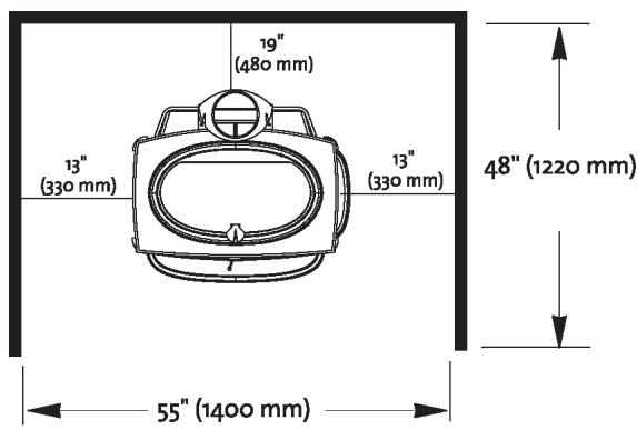
Alcove Installation:
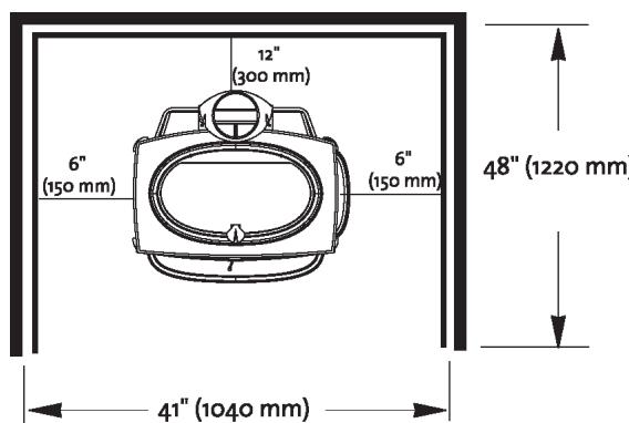
The Jøtul F 600 can be installed in an alcove situation provided: See figures 9 and 10, page 14.
- The stove must be installed with listed double walled pipe.
- In a protected alcove installation both side walls and rear wall must be protected per NFPA 211 or CAN/CSA-B365. The wall protection must be elevated 1" from the floor and at least 1" off the combustible wall to allow for an air-flow.
- The height of the wall protection including the bottom air space must be 48^ .
- The bottom heatshield is required in all alcove installations.
- If a UL/ULC listed hearth pad is not used, the hearth must be constructed of noncombustible material having a minimum R-value of 0.5. (see appendix a, page 19).
- Minimum ceiling height in an unprotected installation, off the top of the stove is 48''(1220mm) . The minimum ceiling height off the top of the stove in a protected ceiling installation is 15''(380mm) .
Use of the right side load door is prohibited in alcove installations. Install Side Door Lock Kit 221100 available from your Jøtul dealer.
Mobile Home Installations:
The Jøtul F 600 has been approved for use in mobile homes in the U.S. and Canada, provided:
- The stove is secured to the floor or the mobile home. Floor mounting kit #750304.
- The stove is provided outside air for combustion. Outside Air kit #154333 (see page 11 for more details)
- The stove must be grounded to the mobile home frame per NFPA 70.
As always, consult with your local building inspector or fire officials about restrictions and requirements in your area prior to installing the stove.
Warning:
Do not install in a bedroom/sleeping room. The structural integrity of the mobile home's floor, wall, ceiling/roof must be maintained.
Operation:
Before building a fire in your new Jøtul F 600, please read the following section carefully and completely.
This stove is designed to burn natural wood only. Wood that has been air-dried for a period of 6 to 14 months will provide the cleanest most efficient heat.
Do not burn:
- Coal * Treated or painted wood
- Garbage * Chemical Chimney cleaners
- Cardboard * Colored paper
- Solvents * Any synthetic fuel or logs
The burning of any of these materials can result in the release of toxic fumes. Never use gasoline, gasoline-type lantern fuel, kerosene, charcoal lighter fluid, or similar liquids to start or "freshen-up" the fire. Always keep such liquids away from the heater at all times.
Important
Never build or allow the fire to rest directly on the glass. The logs should always be spaced at least one inch from the glass to allow for proper air flow within the stove.
Controls on The Jøtul F 600
A single air control lever controls the burn time and heat output of the stove. This primary air control lever is located on the front of the stove directly above the ashlip. The primary air lever controls the amount of air that enters the stove for combustion.
When first starting or reviving the fire: The primary control lever should be at the far right position, which allows the maximum amount of air into the stove.
The more air entering the stove, the hotter the fire, the shorter the burn time. Moving the lever to the left reduces the air-flow into the stove which prolongs the fire at a lower heat output. See figure 11, page 15.
Breaking in Your New Stove
Your new Jøtul F 600 is constructed of cast iron and stove furnace cement. This type of construction requires the stove to be "broken-in" gradually so that heat expansion does not occur too quickly and cause damage.
Complete the following steps for the proper break-in procedure for the Jøtul F 600:
To monitor the stove's temperature, Jøtul recommends the use of a magnetic stove-top thermometer, placed directly on the corner of the stove's top plate.
-
Light a small fire, newspaper and kindling only, only allow the stove to reach a maximum surface temperature of 200^ . Burn for approximately 1 hour.
-
Allow stove to cool to room temperature.
- Light a second fire, allowing the stove to reach a maximum temperature of 300^ for 1 hour.
- Cool the stove to room temperature.
- Light a third fire and gradually allow the stove to reach a surface temperature of 400^
- Cool stove to room temperature. This completes the "break-in" procedure.
Never allow the stove to exceed a 400^ surface temperature during any "break-in fire" with the exception of the last "break-in" fire.
Note: It is normal for a new painted stove to emit an odor and even smoke during its first several fires. This is caused by the seasoning of the high temperature paint and will diminish with each fire and will eventually disappear. Opening a window or door to provide additional ventilation will reduce the odor as this process takes its course.
Starting and Maintaining a Fire
Burn only solid wood directly on the bottom grate of the stove, do not elevate the fire in any way.
- The ash pan door on the stove must always be securely closed when the stove is in operation.
- Burning the stove with the ash pan door open will overfire the stove and cause interior damage.
- With the primary air control lever in the full open position, start with several sheets of crumbled newspaper placed directly on the grate. On top of the newspaper, place several pieces of small dry kindling (approx. 1" in diameter) with two to three larger logs (approx. 3" to 5" in diameter) on top.
- Light the fire and close the door, slowly building the fire by adding larger and larger logs. Be sure to follow the break-in procedure before creating a fire that will damage the stove.
- Once the stove has reached a surface temperature range of between 400^ and 600^ , adjust the primary air control lever as necessary to generate the heat output and burn time desired.
Jotul recommends the use of a magnetic stove top thermometer to monitor the surface temperature of the stove. The optimum surface temperature range for the most efficient burn is between 400^ to 600^ . See figure 12, page 15, for the optimum locations of a stove-top thermometer.
Adding Fuel
When reloading the stove while it is still hot and a bed of hot embers still exist, follow this reloading procedure:
Always wear gloves when tending to the stove.
- Push the air control lever to the full open position (far right).
- Wait a few seconds before opening the door.
- Use a stove tool or poker to distribute the hot embers equally around the firebox.
- Load the fuel, usually with smaller logs first.
- Close the door, be sure to latch the door tightly.
- Wait 5-10 minutes before adjusting the primary air to the desired heat output setting. (If you have at least a 2" thick Ember bed when reloading, it may be possible to close the door and immediately adjust the air control setting).
When wood is burned slowly and at low temperatures, it produces tar and other organic vapors, which combine with moisture to form creosote. The slow moving smoke carries the creosote vapors, which condense in the cooler chimney flues, and this creosote then sticks to the chimney walls.
The creosote that accumulates in the chimney is highly flammable and is the fuel of chimney fires. To prevent chimney fires it is important to have the chimney and chimney connector pipe inspected and/or cleaned semi-annually. A qualified chimney sweep or other authorized service person can provide this service.
It is also important to remember that chimney size, temperature and height all affect draft which in turn affects the formation of creosote. Be sure to follow the installation and operation guidelines established in this manual.
USA/CANADA
Maintenance:
For your protection always wear safety gloves when handling the ash pan.
Ash removal will be required periodically depending on how frequently the stove is used. Conveniently, the Jøtul F 600 is equipped with an ash pan assembly for easy ash removal, without the need for opening the front doors.
The ash pan door is located under the front ashlip of the stove. To open the ash door rotate the door knob counterclockwise to unlatch the door and clockwise to latch the door.
Remove the ash pan. When the stove is in operation always close the ash door before leaving to dispose of the ashes.
The ashes should be placed in a metal container equipped with a tight sealing lid. The container should be placed on a noncombustible floor or on the ground, well away from all combustible materials, pending final disposal. If the ashes are disposed of by burial in soil or otherwise locally dispersed, they should be retained in the closed container until all cinders have thoroughly cooled.
Glass Care
Cleaning:
On occasion it will be necessary to clean the carbon deposits and fly ash off of the glass. If the carbon and fly ash are allowed to remain on the glass for an extended period of time it could eventually cause the glass to become etched and cloudy. Any creosote, which might deposit on the glass, should burn off during the next hot fire.
The proper cleaning procedure is as follows:
- Glass needs to be completely cool.
- Only use a cleaner that is specifically designed for this purpose. The use of abrasives will damage the glass and ultimately leave the glass frosted.
- Rinse and dry glass completely before burning your stove.
Never operate the stove with a cracked or broken glass panel.
Glass removal:
Always operate the doors slowly and cautiously to avoid cracking or breaking the glass. Never use the door to push wood into the firebox. If the glass becomes cracked or broken follow this procedure for replacement:
- Remove the door from the stove and place on a flat surface.
-
Carefully remove all of the glass clips from the inside of the door.
-
Gently remove all pieces of the glass panel and gasketing.
- Remove all remaining debris from the glass area using a wire brush.
- Apply a small bead of gasket/stove cement and the new gasket. Do not overlap the ends of the gasket rope.
- Center the new glass panel over the gasket and reinstall the glass clips. See figure 13, page 15.
Important: The side of the glass treated with an infrared coating (marked on the perimeter) should always be facing outward. It is extremely important to tighten the glass clips slowly and in a repeating pattern, like tightening the lugs on an automobile wheel.
It may be necessary to retighten the glass clips after the stove has burned and the gasketing has been seated.
Important:
Replace glass only with a ceramic glass panel specifically designed for the Jøtul F 600. Do not use substitutes. Replacement glass panels can be ordered through your Jøtul dealer.
General maintenance
Like your car, regular maintenance prolongs the life of your stove. The following procedures do not take long and are generally inexpensive, but when done consistently, increase the life of your stove and in turn, increase your years of enjoyment.
At least once a year you should perform the following maintenance procedures:
- Thoroughly clean the stove. Enamel surfaces should be cleaned with soap and water.
- Empty stove of all soot and ashes. Only use a vacuum for this job if the vacuum is specifically designed for ashes.
- Inspect the stove: Using a strong light inspect the stove inside and out for cracks or leaks. Replace all cracked parts and repair any cement leaks with furnace cement.
Gaskets
Check door and window gaskets for tightness.
To check the seal of the front doors, close and latch the doors on a dollar bill and slowly try to pull the dollar bill free. If it can be easily removed then the seal is too loose. Check several spots around the door, and repeat the procedure on the ash pan door as well.
- If gaskets need to be replaced, scrape out the old gasket and cement and clean the area with a wire brush.
- Apply a small bead of cement and push in the new gasket.
- After closing and latching the doors wipe clean any excessive cement that has come from beneath the gasketing.
| Description | Size | Lenght |
| Right door, | Id375 | ∅9,5 mm (3/8")900 mm (36") |
| Left door, | Id375 | ∅9,5 mm (3/8")900 mm (36") |
| Left door, middle | Id250 | ∅6,4 mm (1/4") 410 mm (18") |
| Right glass,
(42") | Id250 | ∅6,4 mm (1/4") 1 0 5 o | m m |
| Left glass,
(42") | Id250 | ∅6,4 mm (1/4") 1 0 5 o | m m |
| Ash pan door,
(45") | Id250 | ∅6,4 mm (1/4") 1 1 0 o | m m |
| Right side load door, | Id375 | ∅9,5 mm (3/8")1 4 o o | m m |
The Jøtul F 600 is designed to burn cleanly and efficiently when used according to the guidelines expressed in these operating instructions. However, to maintain the proper performance, a yearly chimney inspection and cleaning is necessary. Failure to keep the chimney system free of creosote and build up could result in a serious chimney fire.
Accessories:
Many accessories have been manufactured for use with the Jøtul F 600. Only use accessories that are specifically designed for the Jøtul F 600.
Firescreen
The Jøtul F 600 has been approved for use as an open fireplace, with front doors open. This feature is especially nice when the ambience of a fire is desired. Some care should be taken when operating the stove as a fireplace.
- Always have the firescreen in place, attached to the stove front.
- Never over load the stove: For the best appearance burn in the traditional three log configuration.
- Reminder, when burning the stove with the screen in place, you are sacrificing efficiency for aesthetics, and you will be consuming wood at a much faster rate.
Warning: Operate your Jøtul F 600 with the front doors fully open and the firescreen in place or fully closed. Partially opened doors may result in overfiring. Also, if doors are left partly open, gas and flame may be drawn out of the stove opening, creating risks from both fire and smoke.
Outside Air Kit
In certain installations it may be necessary to provide outside air to your Jøtul F 600 wood stove. Guidelines to determine the need for additional combustion air may not be adequate for every situation. If in doubt, it is advisable to provide additional air.
The outside air kit includes an adapter to mount onto the stove that will accept the fresh air pipe. Installation will require some additional materials:
A. The appropriate length of metallic pipe for a conduit of the outside air (4" diameter).
B. A rain/weather resistant cap for the outside of the house.
C. A rodent screen - that is no larger than 1 / 4 ” mesh.
Outside air may be required if:
- The Jøtul F 600 does not "draw" steadily, smoke rollout occurs, fuel burns poorly, or back-drafts occur whether or not there is combustion present.
- Existing fuel-fired equipment in the house, such as fireplaces or other heating appliances, smell, do not operate properly, suffer smoke roll - out when opened, or back-draft whether or not there is combustion present.
- Opening a window slightly on a calm (windless) day alleviates any of the above symptoms.
- The house is equipped with a well-sealed vapor barrier and tight fitting windows and/or has any powered devices that exhaust house air.
USA/CANADA
- There is excessive condensation on the windows in the winter.
- A ventilation system is installed in the house.
If these or other indications suggest that infiltration air is inadequate, additional combustion air should be provided from the outdoors. Outside combustion air can be provided to the appliance by the following means:
Direct connection: The Jøtul F 600 has been tested and listed for use with an outside air kit. This outside air kit is connected directly to the stove. Be sure to follow the instructions provided with the kit.
Indirect method: Outside air is ducted to a point no closer than (12") 300mm from the appliance, to avoid affecting the performance of the appliance.
A mechanical ventilation system: If the house has a ventilation system (air change or heat recovery):
A.The ventilation system may be able to provide sufficient combustion make-up air for the solid fuel fired appliance.
B.The homeowner should be informed that the ventilation system might need to be rebalanced by a ventilation technician after installation of the appliance.
Floor Bracket Kit
Use of the floor bracket kit is required in all mobile home installations to secure the stove to the floor. Complete installation instructions and diagrams are supplied with each floor bracket kit.
Rear Heatshield
A stove rear heatshield has been specifically designed for the Jøtul F 600 to reduce clearances off the rear of the stove to combustible materials. Use of the heatshield does not affect the clearance off the sides of the appliance.
See pages 11-12 for specific clearance requirements. Complete installation instructions are supplied with the heatshield. No other type of heatshield may be used on the rear of the Jøtul F 600.
Bottom Heatshield
A bottom heatshield has been specifically designed for the Jøtul F 600. It is required in all alcove installations. Use of the bottom heatshield does not affect the floor protection requirements discussed on page 9 of this manual. No other type of heatshield may be used on the bottom of the Jøtul F 600.
Stove-top Thermometer
Jøtul recommends the use of a magnetic stove-top thermometer to monitor the surface temperature of the stove. The optimum surface temperature range for the most efficient, clean burn is between 400^ and 600^ .
Side Door Lock Kit
Use of the Side Door is prohibited in any Corner installation or Alcove installation in which the door is closer than 36" to a combustible wall. Kit 155850 is available specifically for the Jøtul F 600 for use in these cases. With installation, it locks the door latch in a closed position.
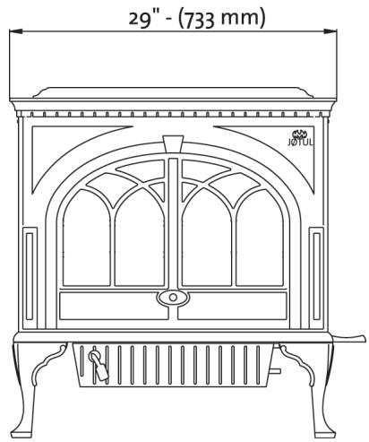
Fig.1a
Fig. 2
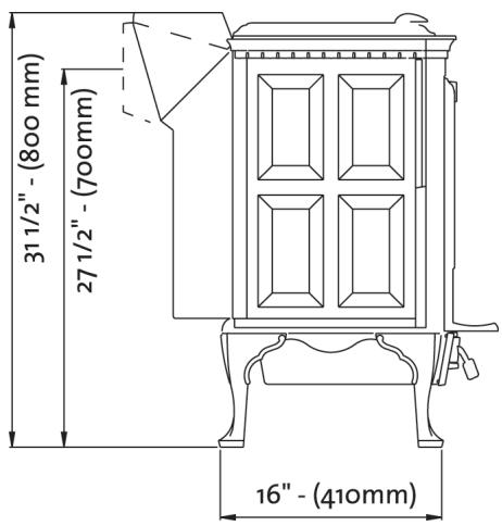
Fig.1b

Fig. 3
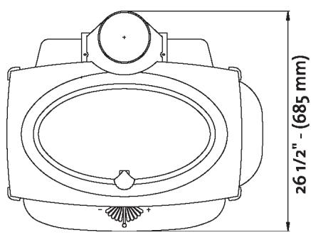
Fig. 1c
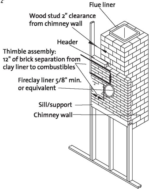
Fig. 4
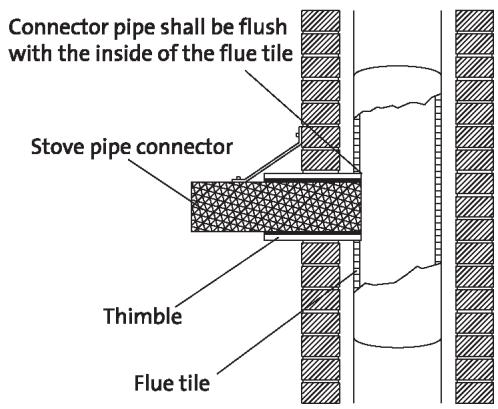
Fig.5
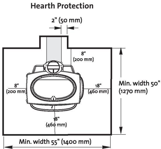
Fig. 8
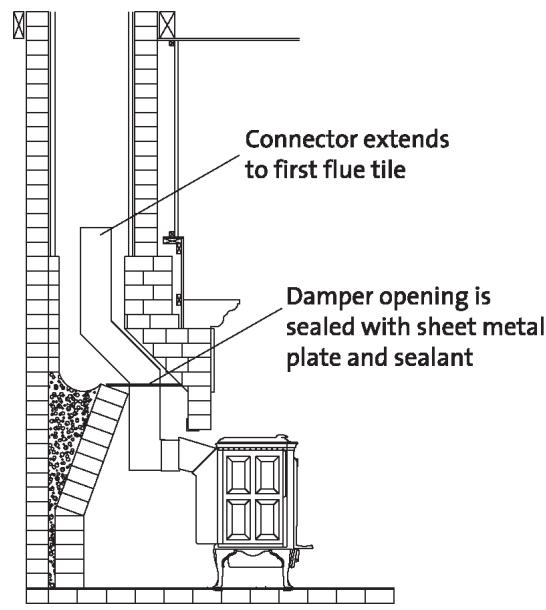
Fig. 6
Fig. 9
Unprotected Alcove Installation
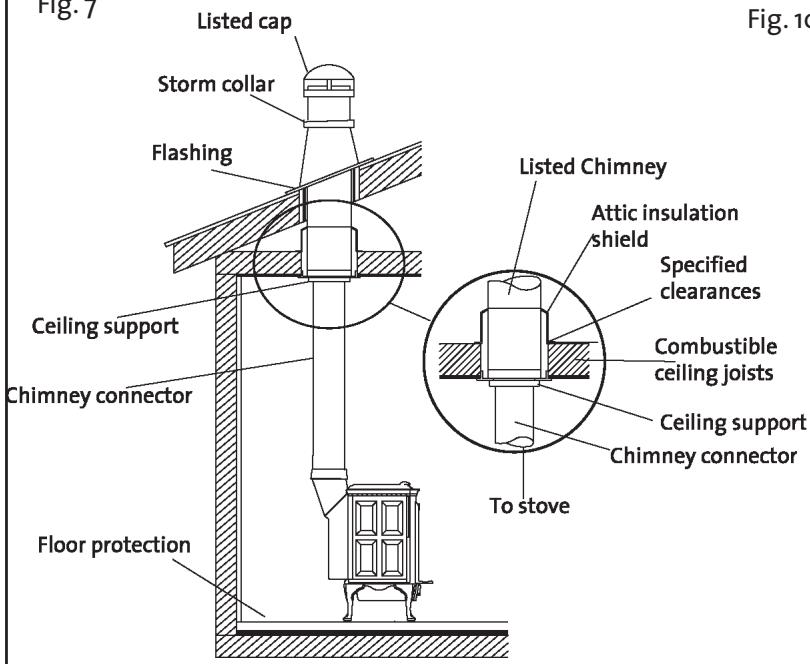
Fig. 7
Fig.10
Protected Alcove Installation
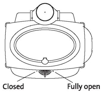
Fig.
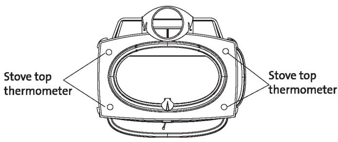
Fig. 12
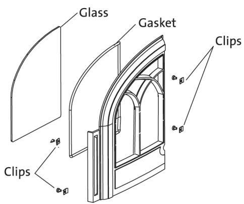
Fig.13
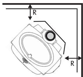
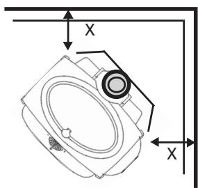
Jøtul F 600 Woodstove Clearances
Unprotected Surface Parallel to the Wall
Protected Surface Parallel to the Wall
PER NFPA 211 or CAN/CSA-B365
Important:
Connector heatshields and double wall pipe must be a listed product. Always follow the manufacturer's instructions.

= SINGLE WALL PIPE WITH CONNECTOR SHIELDS

= DOUBLE WALL PIPE
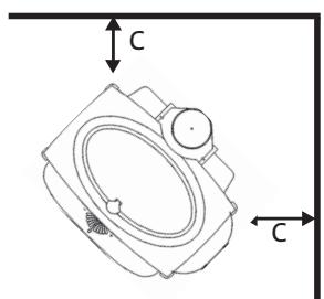
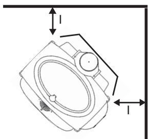
Unprotected Surface Corner Installation
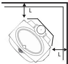
Protected Surface Corner Installation
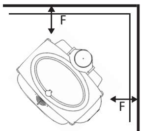
PER NFPA 211 or CAN/CSA-B365
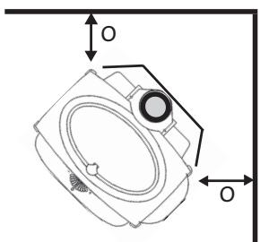
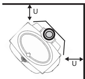
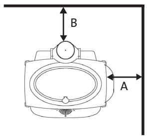
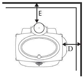
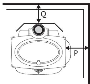
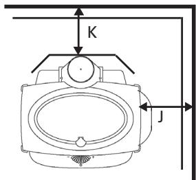
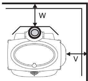
Jøtul F 600 Woodstove Clearances
| Stove clearances | Unprotected surface
Parallel installation | Protected surface NFPA 211
Parallel installation |
| Side | Rear | Corner* | Side | Rear | Corner* |
| Stove- no heatshields | 13" A | 19" B | 13" C | 6" D | 12" E | 9" F |
| Single wall pipe | 330mm | 480mm | 330mm | 150mm | 300mm | 230mm |
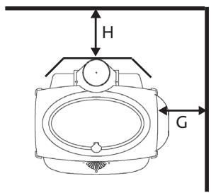
| Stove with rear heatshield | 13" G | 13" H | 10" I | 6" J | 12" K | 9" L |
| Single wall pipe | 330mm | 330mm | 250mm | 150mm | 300mm | 230mm |
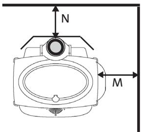
| Stove with rear heatshield | 13" M | 8" N | 10" O | 6" P | 8" Q | 6" R |
| With connector shield | 330mm | 200mm | 250mm | 150mm | 200mm | 150mm |
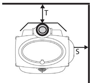
| Stove with rear heatshield | 13" S | 8" T | 9" U | 6" V | 8" W | 6" X |
| With double wall pipe | 330mm | 200mm | 230mm | 150mm | 200mm | 150mm |
| Connector
clearances (pipe) | Unprotected surface
Vertical installation | Protected surface NFPA 211
Vertical installation |
| Single wall pipe | 18" | | | 12" | | |
| 460mm | | | 300mm | | |
| Single wall pipe
with connector shields | 7" | | | 7" | | |
| 180mm | | | 180mm | | |
| Double wall pipe | 6" | | | 6" | | |
| 150mm | | | 150mm | | |
| Connector
clearances (pipe) | Unprotected surface
Horizontal installation | Protected surface NFPA 211
Horizontal installation |
| Single wall connector | 18" 460mm | 12" 300mm | | | | |
| Double wall pipe | 6" 150mm | 6" 150mm | | | | |
| Mantel and trim
clearances | Stove to 1" thick or less, side trim | 11" 280mm |
| Stove to 1" thick or less, top trim | 17" 430mm |
| Stove to mantel- maximum mantel depth 11" | 26" 660mm |
- Attention: Stove and pipe clearances must both be taken into Consideration. The greater clearance dictates the stove's position.
- Use of the right side load door is prohibited in alcove and Corner installations.
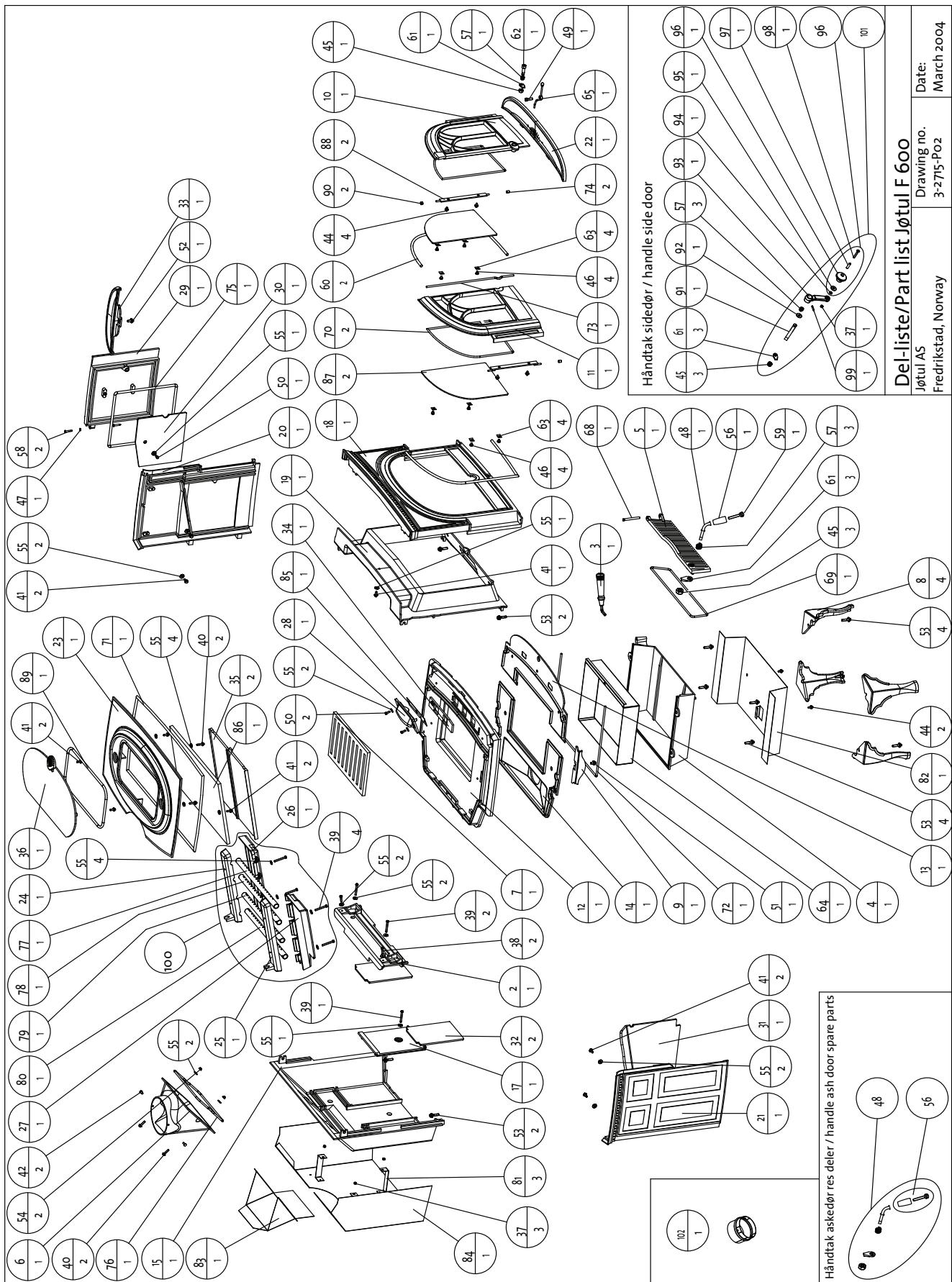
9 Decorative Cover Side
10 Door Right w/o Glass, Ver 3
11 Door Left w/o Glass, Ver 3
12 Bottom
13 Inner Bottom, Front Part
14 Inner Bottom, Rear Part
15 Rear Plate
17 Air Manifold
18 Front
19 Inner Front
20 Side Right
21 Side Left
22 Ash Lip Front
23 Top
24 Tube Holder Upper Right
25 Tube Holder Upper Left
26 Tube Holder Bottom Right
27 Tube Holder Bottom Left
28 Inspection Cover
29 Side Door
30 Burnplate Side Door
31 Burnplate Left
32 Burnplate Rear
33 Ash Lip Side
34 Air Valve
35 Baffle Plate
36 Top Cover
37 Nut Stainless
38 Screw Hexagon Stainless
39 Screw Hexagon
40 Screw Collar Hexagon
41 Screw Collar Hexagon
42 Screw Selfthread
43 Screw Collar Hexagon
44 Screw Collar Hexagon
45 Nut Hexagon
46 Screw Panh. (Front Door)
47 Washer
48 Latch Bolt Ash Door
49 Screw Allen
50 Screw Hexagon Stainless
51 Screw Collar Hexagon
52 Screw Collar Hexagon
53 Screw Collar Hexagon
54 Nut Collar Hexagon
55 Washer
56 Wooden Knob Ash Door
57 Spring for Latch Bolt
58 Hinge Pin Front/Side Door
59 Screw Syl. Head
60 Gasket (Door to Front)
61 Latch
62 Latch Bolt
63 Glass Clip
64 Ash Pan
65 Handle for Air Vent
68 Hinge Pin, Ash Door
69 Gasket (Ash Door)
70 Gasket (Glass)
71 Gasket (Top)
72 Gasket (Ash House)
73 Gasket (Left Door Middle)
74 Sleeve for Door Hinge
75 Gasket (Side Door)
76 Gasket (Smoke Outlet)
77 Tube First From Front
78 Tube Second From Front
79 Tube Third From Front
80 Tube Forth From Front
82 Bottom Heatshield
83 Heatshield Top Exit
84 Rear Heatshield
Pos.
no.Description
85 Air Restrictor
86 Insulation Blanket
87 Glass
88 Front Door Hinge
89 Gasket (Top Cover)
90 Shaft Collar 6× 12× 6mm
91 Latch Bolt Side Door
92 Washer
93 Latch
94 Washer
95 Washer, Insulating
96 Wooden Knob Side Door
97 Distance Sleeve for Side Door
98 Screw Pan Head
99 Pin
100 Air Chamber Complete
101 Handle Side Door Complete
102 Adapter Outside Air
Alternate floor protection
All floor protection materials must be non-combustible ie. metal, brick, stone, mineral fiber boards). Any combustible material may not be used.
The easiest means of determining if a proposed alternate floor material meets requirements listed in this manual is to follow this procedure.
R-value = thermal resistance
k-value = thermal conductivity
C-value = thermal conductance
- Convert the specification to R-value;
a. If R-value is given, no conversion is needed.
b. If k-value is given with a required thickness (T) in inches: R = 1 / k× T
c. If C-value is given: R = 1 / C
- Determine the R-value of the proposed alternate floor protector.
a. Use the formula in Step 1 to convert values not expressed as “R”.
b. For multiple layers, add R-values of each layer to determine overall R-value.
- If the overall R-value of the system is greater than the R-value of the specified floor protector, the alternate is acceptable.
Example:
The specified floor protector should be 3/4 "thick material with a k-factor of 0.84. The proposed alternate is 4 "brick with a C-factor of 1.25 over 1/8 "mineral board with a k-factor of 0.29.
Step A. Use formula above to convert specifications
to R-value. R = 1 / k × T = 1 / .84 × .75 = .893
Step B. Calculate R of proposed system.
4" brick of C-1.25, therefore
R brick = 1 / C = 1 / 1.25 = 0.80
1/8" mineral board of k = 0.29 therefore
R mineral board = 1 / .29 × 0.125 = 0.431
Total R = R brick + R mineral board=
0.8 + 0.431 = 1.231
Step C. Compare proposed system R = 1.231 to specified R of 0.893. Since R is greater than required, the system is acceptable.
Definitions:
Thermal conductance =
$$
C = \frac {B t u}{(h r) (f t ^ {2}) (F)} = \frac {W}{(m ^ {2}) (K)}
$$
Thermal conductivity =
$$
k = \frac {B t u}{(h r) (f t ^ {2}) (F)} = \frac {W}{(m ^ {2}) (K)} = \frac {(B t u)}{(h r) (f t) (F)}
$$
Thermal resistance =
$$
R = \frac {B t u}{(h r) (f t ^ {2}) (F)} = \frac {(m ^ {2}) (K)}{W} = \frac {(B t u) (i n c h)}{(h r) (f t ^ {2}) (F)}
$$
Alcove installations require noncombustible hearth materials having a minimum insulating R-value of 0.5.
NORSK
Innhold
Montering for installations 21
Relationship to the authorities
Technical data of Jøtul F 600 25
General safety precautions 26
Measures to prevent fire danger. 26
Installation of Jøtul F 600
Foundations 26
Chimney 26
Air circulation 26
Assembly prior to installation 26
Control of functions 26
Mounting of flue pipe 27
Connection to chimney 27
Operating instructions
Initial lighting and daily use 27
Initial lighting. 27
Daily use 27
Maintenance
Cleaning the glass. 28
Ash removal 28
Cleaning and soot removal 28
Sweeping of flue pipes to the chimney 28
Control of the stove 29
External maintenance. 29
The length, quantity and quality of logs 29
Jotul's definition of quality wood 29
Service
Changing the burn plates 29
Changing the baffle plate 29
Optional equipment
Connecting pipe for outdoor ventilation 29
Figures - drawings. 59
Relationship to the authorities
Jøtul F 600 is a clean-burning product.
The product data plate is located on the heat shield and is made of heat-resistant material. The following information is listed on the data plate: Manufacturer and address, model number, manufacturing number, rated heat output, registration number (after assignment), style, and safety measurements. The plate can be fastened at the back of the U.S. rating plate or at the back of the heat shield.
Installation of a fireplace must be according to local codes and regulations in each country. Always contact you local building inspector or the appropriate authority responsible for local codes and regulations in your district. Your dealer has been specially selected for his knowledge of your local codes and may provide assistance in ensuring that your installation is safe and legal.
Warning! Please ensure that there is adequate ventilation in the room in which the stove is to be installed. Using a fireplace requires a plentiful supply of fresh air to the room where the product is installed. If the house is sealed, the room ought to be equipped with extra fresh air supply through vents. Avoid using mechanical fan vents in a room with a fireplace. This may cause negative pressure and draw poisonous gases into the room.
NB! This can lead to drowsiness, nausea and sickness and is extremely dangerous.
Instructions for mounting, installation and use are enclosed with the product. The installation may only be used when it has been inspected by a qualified controller.
Technical data of Jøtul F 600:
Material: Cast iron
Finish: Black paint, blue-black and ocean green enamel
Fuel: Wood
Log length, max.: 55 cm
Draught system: Top and bottom draught
Combustion system: Secondary combustion
Flue outlet: Top/rear
Fluedimension: 150 mm dia.
Can steel pipe be fitted: Yes
Approx. weight: 200 kg
Product measures, distance measures to protected/
unprotected wall: See fig. 1 and 2.
ENGLISH
General safety precautions
Requirements for the floor plate: If the stove is to be installed on a floor made of a flammable material, the whole floor underneath the stove, and at least 500mm in front of the stove and to the right of the stove, must be covered by a plate made of a non-flammable material (see measures fig.2). The size of the plate depends on the local codes and regulations, and we recommend that you contact the local Jøtul dealer prior to installation.
Distance to firewall or protected wall:Contact your local building authorities regarding restrictions and installation requirements.
The product side door should not be used when the stove is installed in a recess or corner.
Uninsulated flue pipe: If uninsulated flue pipes go through floors or walls, require that the opening must be made of brick or masonry, in such a way that the external surface of the pipe does not get closer than 230mm to any flammable materials. Isolated flue pipes may have a different distance, if necessary refer to fire technical product documentation for the flue pipe.
Measures to prevent fire danger
Any use of the fireplace may represent some danger. Therefore, respect the following instructions:
Always use a spark catcher if the product is to be utilised with an open door.
- Ensure that furniture and other flammable materials do not get too close to the fireplace. There ought to be a safe distance from the front of the fireplace to flammable material. Check your local codes and regulations.
- Let the fire die. Never put it out with water as this may damage the product.
- The fireplace gets hot when used and may cause burns if touched.
- Ash must be properly disposed of outdoors, or emptied where it does not entail a fire hazard. Refer to local regulations.
- Any stove should have a storage container made of non-flammable material as a standard accessory for the safe disposal of soot and ashes. Soot and ashes must be stored in this container for at least a week in order to be certain that the lastember has been extinguished. If the container needs to be emptied before this, add plenty of water to the container and stir.
- You may want to keep the ash. It is a first class fertilizer for roses and other plants.
Installation of Jøtul F 600
Note! Check that the stove is free of any damage prior to commencing installation.
The product is heavy! Make sure you have assistance when erecting and installing it.
Foundations
If Jøtul F 600 is to be installed on a wooden structure, ensure that the floor under the stove has the proper support to carry the stove.
Chimney
The stove can be connected to a brick, pre-fabricated element or Jotul steel chimney. See separate section. Minimum chimney cross section must be 177~cm^2 (Corresponding to 150 mm dia.). Connection to chimney must be done in accordance with the installation instructions from the supplier of the chimney.
Air circulation
Using a fireplace requires a plentiful supply of fresh air to the room where the product is installed. If the house is sealed, the room ought to be equipped with extra fresh air supply through vents. Avoid using mechanical fan vents in a room with a fireplace. This may cause negative pressure and draw poisonous gases into the room.
In order to avoid this, it is possible to bring in outside air directly to the stove by using an adapter (extra unit) that is mounted to the air inlet of the stove. From there a flexible hose is conducted out of the house. The installation instruction for this is enclosed with the installation unit.
Assembly prior to installation
The product is delivered in one package. A loose handle for the door is also included. The oval top plate is fastened with screws during transport. Remove the screws from underneath the top plate and leave it unattached. This makes it easier for the chimney sweep when the product and the flue pipe have to be cleaned.
Undo the ash lips, which are fastened to the top, and install. The one in front is placed loosely on top of the base plate, while the side ash lip is fastened with the screw that is attached to the base plate.
Control of functions (fig. 3)
When the product is set up, always check the control functions. These shall move easily and function satisfactorily.
Draught vent (A)
Left position = closed.
Right position = fully open.
Doorhandle (B)
Towards the left = open. Towards the right = closed.
Doorhandle (C)
Towards the right = open. Towards the left = closed.
Ash door (E)
Open the door by turning the handle counter-clockwise one half rotation. Use a glove or similar and pull out the tray.
Note! Only remove the ashes when the stove is cold
Mounting of flue pipe
It is advisable to carry out a test assembly prior to making a hole in the chimney. See fig. 2 for measures to wall made of flammable materials. The stove is installed with a 150mm diameter flue pipe. This must be an approved thickness. The flue outlet for Jøtul F 600 is inside the burn chamber during transportation. You can choose between a top or rear outlet from the flue pipe. The screws for fastening are in the bag containing screws.
- Flue pipes 150 ~mm dia. are placed directly onto the product flue outlet. There is a screw on both sides of the product flue outlet (fig. 4-A). These are used to fasten the flue pipe.
- Mark where the screws hit the flue pipe when it is at the very bottom of the flue outlet and drill a 5,5 mm hole for the screw in the flue pipe.
- Use gasket and cement to seal between flue pipe and product flue outlet. Place the gasket around the lower part of the flue pipe and fill up the space with cement.
- Fasten the flue pipe with screws.
Note! It is important that the joints are completely sealed.
Air leakage etc. may lead to malfunction.
Connection to chimney
Drill a hole for the flue pipe. Distance from stove to firewall/chimney should be as shown in fig. 2. Always use a chimney collar when connecting to chimney. Use the supplier's recommended chimney collar when connecting to an element chimney. Follow the supplier's assembly and usage instructions closely with regard to mortar/furnace cement before starting to use the fireplace.
Ensure that the flue pipe never slopes down towards the chimney. It should at least be horizontal, preferably have an incline of a few millimeters.
Note! A correct and sealed connection is very important for the proper functioning of the product.
Be alert to the fact that it is particularly important that connections have a certain flexibility. This is to prevent setting of the house from leading to fissuration.
Operating instructions
Initial lighting and daily use
Jøtul F 600 is a clean-burning product and with additional supplies of combustion air, it allows for afterburning of hazardous gases and particles. It is important that the system is used correctly.
The stove is equipped with certain functions that are described in the chapter: Control of functions.
Initial lighting
Open the draught vent fully by pushing the vent all the way to the right (fig. 3-A). Put in some crumpled newspaper, kindling wood and firewood and start a small fire. Add more firewood gradually and let the fire burn briskly for a couple of hours. Let the fire die out and repeat one more time.
Note! Odors when using the stove for the first time.
Painted products. The stove may emit an irritating gas when used for the first time, and it may smell a little. The gas is not toxic, but it is recommended to open a window or a door to provide additional ventilation in the room. Let the fire burn with a high draught until all traces of gas have disappeared and no smoke or smells can be detected.
Enamelled products: Condensation may form on the surface of the stove the first few times it is used. This must be wiped off to prevent permanent stains forming when the surface heats up.
Daily use
Fire up with the aid of newspapers and some kindling wood. Place two medium sized logs in/out on each side of the base. Crumple some newspaper (or birch bark) between these and add some kindling wood in a criss-cross pattern on top and light the newspaper. Increase the size of the logs gradually.
Draught vent (fig. 3-A). Regulate when the wood is properly lit and burns well. Check that the afterburning (secondary combustion) starts. This is best indicated by yellow, flickering flames in the air chamber. Then regulate the rate of combustion to the desired level of heating by adjusting the draught vent.
Always use good quality firewood. It gives the best results and does not damage the product.
Never burn the following materials in the stove:
household waste, plastic bags etc.
- painted or impregnated wood (highly toxic)
chipboard or laminated boards
driftwood
This may harm the product and pollute the atmosphere.
ENGLISH
Note! Never use flammable liquids such as petrol, kerosene, red spirit or similar to start the fire. This may cause harm to both yourself and the product.
Note! Danger of overheating: The stove must never be used in a manner that causes overheating.
Overheating is defined as overfilling the stove with firewood and/or leaving the draught vent fully open.
The chimney draught should never exceed 2,5 mmVs (25 Pa). A sure sign of overheating is when parts of the stove glows red. When this happens, reduce the draught vent opening immediately. (Move draught vent to the left).
Warning! Each fire should burn down to embers before new firewood is added.
Maintenance
Cleaning the glass
Jøtul F 600 is equipped with top draught (air wash). Through the draught vent air is sucked in above the fireplace and washed down along the inside of the glass. This system has the advantage that it provides better combustion and reduces the buildup of soot deposits on the glass.
Still, some soot will always stick to the glass, but the quantity will depend on the local draught conditions and adjustment of the draught vent. Most of the soot layer will normally be burned off when the draught vent is opened all the way and a fire is burning briskly in the fireplace.
Good advice! For normal cleaning, moisten a paper towel with warm water and add some ash from the burn chamber. Rub it over the glass and then clean the glass with clean water.
Ash removal
Jøtul F 600 has an ash pan which makes it easy to remove the ash. Scrape the ash through the grate in the base plate and into the ash pan. Use something like a glove to grab the handle on the ash pan and take away the ash. Make sure that the ash pan doesn't fill up so high that it keeps ash from coming through the grate into the pan.
Make sure the door to the ash pan is securely shut when the stove is in use.
It is always an advantage if some ashes remain in the burn chamber as a protective layer against the oven base. Also see the description of how to handle ashes under "Measures to prevent fires".
Cleaning and soot removal
Soot deposits may build up on the internal surfaces of the stove during use. Soot is a good insulator and will therefore reduce the stove's heat output.
An annual internal cleaning is necessary to get the best heating effect from the product. It is a good idea to do this in connection with the sweeping of the chimney and flue pipes.
Sweeping of flue pipes to the chimney
Sweeping of the flue pipes is carried out by lifting the loose oval top plate. This gives easy access for sweeping. It is possible to sweep through the sweeping hatch in the flue pipe or through the product door opening. In that case the baffle plate has to be removed first. See appropriate sections under: Service.
Control of the stove
Jøtul recommends that you personally control your stove carefully after sweeping/cleaning. Check all visible surface areas for cracks. Also check that all joints are sealed and that the gaskets are in the correct position. Any gaskets showing signs of wear or deformation must be replaced.
Thoroughly clean the gasket grooves, apply ceramic glue (available from your local Jøtul dealer), and press the gasket well into place. The joint will dry quickly.
External maintenance
Painted products may change color after several years usage. The surface should be cleaned and brushed free of any loose particles before new Jøtul stove paint is applied.
Enamelled products must only be cleaned with a clean, dry cloth. Do not use water and soap. Any stains can be removed with a cleaning fluid (Oven cleaner etc.).
The length, quantity and quality of logs
The maximum length of logs to be used is 55~cm . Logs should be placed parallel to the back wall of the combustion chamber. Minimum heat emission from Jøtul F 600 is ca 3.5kWh , and the nominal capacity 10kWh . The calculated requirement for nominal heat emission is approx. 4,0 quality wood per hour.
Jøtul's definition of quality wood
Good quality wood should be dried so that the water content is approx. 20% .
To achieve this, the wood should be cut during late winter or early spring. It should then be cut and stacked to ensure proper airing. The stacks should be covered to prevent them from absorbing too much rainwater. The logs should be taken indoors in autumn for use during the winter season.
With good quality firewood we mean logs from trees, such as birch, beech and oak.
The amount of energy obtainable from 1kg of wood varies very little. On the other hand, the specific weight of the different kinds of wood varies considerably. As an example, a certain volume of birch will provide less kWh than the same volume of oak, which has a higher specific weight.
The amount of energy in 1 kg quality wood is approx. 3,8 kWh.1 kg of completely dry wood (0% humidity) produces approximately 5 kWh, while wood with a humidity level of 60% produces only around 1.5 kWh/kg.
Service
Changing the burn plates
- The stove has burn plates on the sides and in the back. The burn plate on the right door is fastened with a screw.
- To remove, unfasten the screw and remove the burn plates.
- To install, follow the same procedure.
Changing the baffle plate
- The baffle plate consists of 2 cast iron plates and rests on top of the pipes that supply secondary air.
- To remove, lift a little upwards in the middle and take them out.
- To install, replace both plates in the same manner. Make sure they are fitted closely against the back wall.
- Then place the insulating blanket on top of the baffle plates.
Optional equipment
Connecting pipe for outdoor ventilation - Cat. No. 221032
With the aid of a connecting pipe for outdoor ventilation and a flexible tube, combustion air can be connected to the product directly from the outside. In this manner, the fireplace will always be supplied with the air needed to achieve proper combustion.
FRANCAIS
Sommaire
Regimentations nationales
Stookplaten verrangen
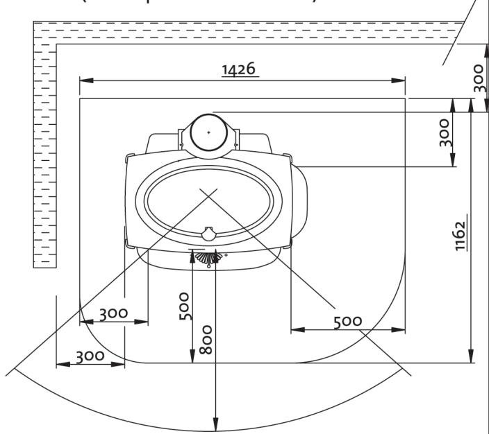
Fig. 2
Measurements according to VHR (with optional heatshield)

Fig.1b
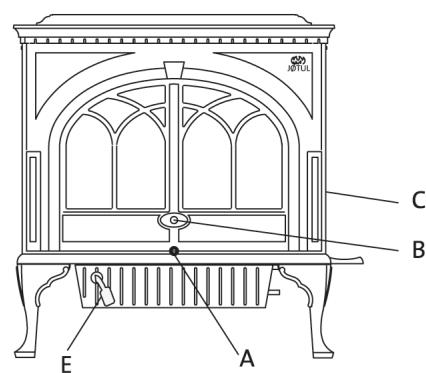
Fig. 3
Fig. 1c
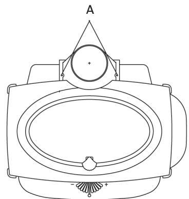
Fig. 4
| Cat.no.129211
Draw.no.4-3600-P03
Mokkegaard's Trykkeri AS, March 2006 |
| JØTUL® |
Jøtul pursue a policy of constant product development. Products supplied may therefore differ in specification, colour and type of accessories from those illustrated and described in the brochure.
Jøtul AS has a quality system that conforms to NS-EN ISO 9001 for product development, manufacturing, and distribution of stoves and fireplaces. This policy gives our customers quality and safety piece of mind as a result of Jøtul's vast experience dating back to when the company first started in 1853.
Qualité
This product has been controlled by: