
POWER AMPLIFIERS - Audio Amplifiers FOCAL - Free user manual and instructions
Find the device manual for free POWER AMPLIFIERS FOCAL in PDF.
| Product Type | Audio amplifier for Car Audio system |
| Brand | FOCAL |
| Available Models | FP 2.75, FP 2.150, FP 4.75, FP 5.500, FP 1.800 |
| RMS Power (at 4 Ω) | FP 2.75: 2x75W; FP 2.150: 2x150W; FP 4.75: 4x75W; FP 5.500: 4x75W + 1x200W; FP 1.800: 1x400W |
| RMS Power (at 2 Ω) | FP 2.75: 2x100W; FP 2.150: 2x200W; FP 4.75: 4x100W; FP 5.500: 4x100W + 1x300W; FP 1.800: 1x600W |
| Bridged Power (at 4 Ω) | FP 2.75: 1x200W; FP 2.150: 1x400W; FP 4.75: 2x200W; FP 5.500: 2x200W + 1x200W; FP 1.800: not applicable |
| Signal-to-Noise Ratio | >100 dB (A) |
| Damping Factor | FP 2.75/2.150: >500; FP 4.75/5.500/1.800: >200 |
| Frequency Response | 10 Hz - 35 kHz (FP 1.800: 10 Hz - 300 Hz) |
| Input Impedance | 13 kΩ |
| Input Sensitivity | 0.2 - 5 V |
| High-Pass Filter | 50-150 Hz, 12 dB/oct (except FP 1.800) |
| Low-Pass Filter | 50-150 Hz, 12 dB/oct (FP 1.800: 24 dB/oct) |
| Subsonic Filter | FP 5.500: 25 Hz, 24 dB/oct; FP 1.800: 15-50 Hz, 24 dB/oct |
| Bass Boost | 0/12 dB (FP 1.800 with adjustable frequency 20-80 Hz) |
| Variable Phase | FP 5.500: 0/180°; FP 1.800: 0-180° |
| Remote Controls | FP 5.500 and FP 1.800 (gain control) |
| Power Supply | 12 V battery, standby consumption 0.8-1 A |
| Protections | Short circuit, DC offset, overheating, clipping limiter, overvoltage, reverse polarity |
| Dimensions (H x W x D) | FP 2.75: 50x230x280 mm; FP 2.150/4.75: 50x350x280 mm; FP 5.500: 50x500x280 mm; FP 1.800: 50x320x280 mm |
| Warranty | 1 year (France) |
| Usage | 12 V mobile application only |
Frequently Asked Questions - POWER AMPLIFIERS FOCAL
User questions about POWER AMPLIFIERS FOCAL
0 question about this device. Answer the ones you know or ask your own.
Ask a new question about this device
Download the instructions for your Audio Amplifiers in PDF format for free! Find your manual POWER AMPLIFIERS - FOCAL and take your electronic device back in hand. On this page are published all the documents necessary for the use of your device. POWER AMPLIFIERS by FOCAL.
USER MANUAL POWER AMPLIFIERS FOCAL
We thank you for choosing Focal amplifiers for your Car Audio system and for sharing our philosophy: "the Spirit of Sound". This product offers the latest advances in Focal amplifiers. In order to obtain the best results, we highly recommend you have your new amplifier installed by your local Focal distributor. To maximise the use of all the functionalities of your amplifier and to fully enjoy its performance levels, we recommend that you read the entire instructions in this booklet, and then keep it in a safe place for future reference. Any problems caused by not respecting the rules of use may render your guarantee null and void.
In order to validate your guarantee, please fill out and return the last page of this document within 10 days of purchase.

WARNING
This symbol denotes important instructions. Non respect of these instructions may lead to serious injuries and even fatal injuries.

CAUTION
This symbol denotes important instructions. Non respect of these instructions may lead to injury or material damage
Contents of the packaging:
- 1 amplifier
-1user'smanual - 4 mounting screws
- Fuses
- 1 remote control (only supplied with the FP 1.800 and FP 5.500 amplifiers)
- 5m cable for remote control (only supplied with the FP 1.800 and FP 5.500 amplifiers)
- 1 quality control sheet
- Allen keys


C E
Français page 25
- Do not turn on any function which may distract you while driving the vehicle. Functions requiring sustained attention must only be used when the vehicle is at a complete standstill. Make sure to always stop your vehicle in a safe place before operating these functions. There is a risk of causing an accident.
- Keep the volume at a low level so as to be able to hear exterior noises while driving the vehicle. There is a risk of causing an accident.
- Do not open the amplifier or undertake any modifications of the product. There is a risk of accident, fire or electric shock.
- Only use this amplifier with 12V. mobile applications. Any other use other than the use for which this product has been designed may lead to fire, electric shock or injury.
- Use fuses of the correct amperage. There is a risk of fire or electrocution.
- Do not obstruct radiators and/or vents. Internal overheating may occur and cause a fire.
- Ensure all connections are properly made. Check the section of cable and the type of cable if it does not correspond with the use. There is a risk of fire, injury and/or damage to the product.
- To be used only with 12V. batteries. Check with your distributor if required. There is a risk of fire, injury and/or damage to the product.
- Do not use nuts or fasteners part of the steering or braking systems for ground connection. The fasteners and nuts used for the brake and steering systems (or any other security system) as well as various tanks must never be used for grounding. Use of these parts as ground may deactivate the vehicle's control system and cause a fire or other technical problem.
- Keep all small objects which could be swallowed, such as the fasteners and screws, out of the reach of children. Swallowing such objects may cause serious injuries. In the event of swallowing any of these objects, seek medical advice immediately.
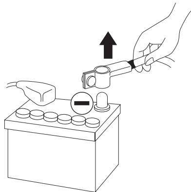
- Before commencing the installation, disconnect the negative terminal of the battery to avoid any risk of injury, fire or damage to the equipment.
Listening for prolonged period at a high volume level, over 100dB, can lead to permanent deterioration of your hearing. Listening at a volume of over 130dB, even for short periods of time, can cause incurable damage and injury to your hearing.
Stop operation in the event of a problem. Failure to heed this precaution may result in injuries or damage to the product. If a problem persists, return the product to your Focal distributor for repair.
Use the specified accessories and be sure to install them correctly. Only use the accessories specified in the user's manual and those which are supplied with the package. The use of other components could cause internal damage to the product, and their installation risks to not being correctly installed. The parts being used risk becoming loose and causing damages or technical faults with the product.
Do not assemble in very humid or dusty places. Avoid assembling the product in places with high levels of humidity or an excessive presence of dust. Humidity or dust getting inside the product may cause a technical fault.
Installation of the amplifier
The installation of this product requires technical knowledge and experience. In case you are uncertain of your ability to correctly install the amplifier, we strongly recommend you contact your Focal distributor to install it for you, so that you will be able to take full advantage of all the different possibilities of the amplifier.
Wiring of the amplifier
Only use the wires recommended in this manual. The loudspeaker wire must ONLY be used for connecting the amplifier to the loudspeakers. The section of power cables must correspond with that which is detailed in the table (p. 7) and correspond with the power of the amplifier and the length of the cable. Use double or triple shielded RCA cables to avoid any interference of the low level signal.
Duration of operation of the amplifier
Avoid operating the amplifier for a long period of time (from 10 to 30 minutes depending on the amplifier) without starting the vehicle. Extensive use before starting the vehicle's engine may lead to the battery going flat.
Material required for the installation:
- 2 conduits of suitable cross-section (1 conduit for the power cable, 1 conduit for the loudspeaker, REMOTE,
- RCA signal and REMOTE CONTROL cables).
- Multimeter (voltage/amperage)
- Soldering iron + solder
- Crimping tool
- Stripping pliers
- Wire cutter
- Spanner for battery terminal
- Hand drill and assorted drills
- Heat shrinks of suitable diameter for the different cables.
Power cable of suitable length and section - Remote switch on cable (REM input) of suitable length and section
Ground cable of suitable length and section - Assorted connectors
- Fuse holder and suitable fuse
- Joint tag for the battery's positive (+) terminal
- Joint tag for the vehicle's chassis (-)
- Screw with minimum 6mm screw head and its nut for ground connection to the chassis of the vehicle.
The below section deals with issues regarding the vehicle which are necessary to take into account for the installation of the amplifier. You'll save time by planning the system layout and wiring in advance. Ensure that during this preliminary step all the adjustments are accessible once the installation is complete.
Before starting the installation, please follow the following rules carefully:
1 - After reading the whole manual, be sure that you have understood all the instructions before installing the amplifier.
2 - Disconnect the battery's negative wire before starting the installation. (fig. 1).
3 - To facilitate the assembly, we strongly recommend that you unwind all the wires before installing the amplifier.
4 - Put aside all the RCA cables, loudspeaker, REM and REMOTE CONTROL {REMOTE CONTROL only supplied with models FP 1.800 and FP 5.500} from the power cables in order to avoid any interference of the signal.
5 - Use quality connectors to ensure a reliable installation and to minimise any losses of signal or power.
6 - Think carefully before drilling anything. Be extremely careful not to cut or drill the petrol (fuel) tank, the fuel, brake, hydraulic or vacuum pipes, as well as the electrical wiring.
7 - Never route a wire under the vehicle. It is absolutely imperative to install them inside the vehicle for better protection. While routing the wires, verify that they do not impair the driving of the vehicle. Cables obstructing or routing through areas such as the steering wheel, pedals (brake, accelerator and clutch, etc.) may be extremely dangerous.
8 - Avoid routing wires above or through sharp rims. Any wire routed through metal must be protected with a grommet. Route the wires well away from mobile parts (seat rails,...) and from sharp or pointed cutting edges. This will avoid catching or damaging the wires.
9 - Always protect the battery and electrical circuit from potential damages with the help of fuses. Install a fuse holder and suitable fuses on the 12V positive (+) power cable at less than 40cm from the battery terminal. Ideally, this abovementioned distance should be the shortest possible. (fig. 7).
10 - Prepare the chassis ground by scraping any trace of paint on the metal surface in order to ensure correct grounding. The grounding connections should also be as short as possible and ALWAYS connected to the metal welded to the body or the chassis of the vehicle. (fig. 4).
11 - NEVER install this product in the engine compartment of the vehicle. This will void the guarantee.
I - Set-Up and Cabling
Where to install the amplifier?
The amplifier power is such that substantial heat is generated when it is operation. This is why the amplifier has to be placed in a well-ventilated area of the car.
2 - Attaching the Amplifier (fig. 2)
The surface onto which you want to attach the amplifier (boot of the car, etc.) may not be smooth enough (due to bumps, ribs, etc) to make it easy or even possible to fasten the amplifier. If this is the case, we recommend that you mount the amplifier and its attachment system on a wooden base – i.e. MDF, plywood – which itself is attached to the surface in question.
Position the amplifier at the desired location. Mark the location of attachment holes using appropriate means - i.e. an indelible marker, a screwdriver, etc. Make sure that there is nothing below the surface which could be damaged during drilling - i.e. tanks, bundles of cables, etc. Remove the amplifier, making sure that you are using a 3mm-diameter drill bit, and then drill. Put the amplifier back into the initial position you chose for it. Attach the amplifier using the four self-tapping screws supplied. For additional help, see the "General Installation Guidelines" section.

WARNING
Think carefully before drilling anything. Be extremely careful not to cut or drill the petrol (fuel) tank, the fuel, brake, hydraulic or vacuum pipes, as well as the electrical wiring.
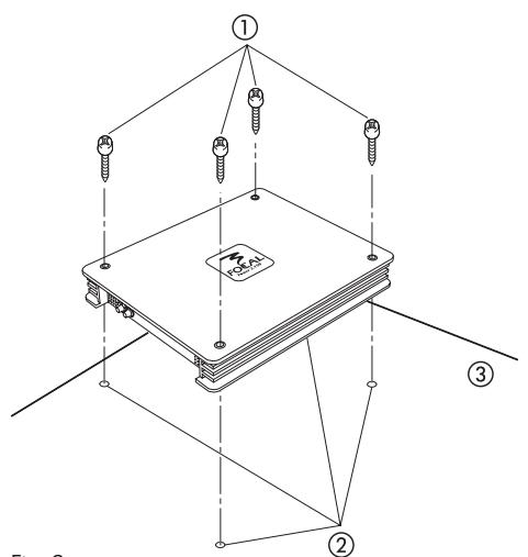
Fig. 2
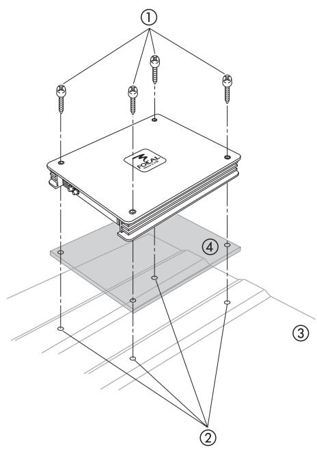
① - Screws
② - Holes
③ - Steel base
(4) MDF base
3-Cabling

WARNING
If there is a doubt as to your ability to install the amplifier and to cable the system properly, get a Focal distributor to do it for you.

WARNING
Before you begin the connection phase of set-up, remove the vehicle battery's negative (-) terminal. (fig. 1).

CAUTION
Avoid routing power supply cables close to low-level input cables (RCA), to your car's radio aerial, or to sensitive units. High-current power supply cables can cause static/interference that affects audio signals.

CAUTION
Keep cables as short as possible to optimise the system's set-up performance and to reduce signal loss.
3.1 - What power supply wire gauge should I use?
| Amplifiers | Main fuse | Length of Cable in Metres | ||||||
| 0-1m | 1-1.8m | 1.8-2.5m | 2.5-3.3m | 3.3-4.1m | 4.1-5.6m | 5.6-7.1m | ||
| Power 2.75 | 1 x 40A | 8mm² | 10mm² | 10mm² | 16mm² | 16mm² | 25mm² | 25mm² |
| 8AWG | 7AWG | 7AWG | 5AWG | 5AWG | 3AWG | 3AWG | ||
| Power 2.150 | 2 x 40A | 16mm² | 16mm² | 25mm² | 25mm² | 35mm² | 35mm² | 53mm² |
| 5AWG | 5AWG | 3AWG | 3AWG | 2AWG | 2AWG | 0AWG | ||
| Power 4.75 | 2 x 40A | 16mm² | 16mm² | 25mm² | 25mm² | 35mm² | 35mm² | 53mm² |
| 5AWG | 5AWG | 3AWG | 3AWG | 2AWG | 2AWG | 0AWG | ||
| Power 5.500 | 4 x 30A | 25mm² | 25mm² | 25mm² | 35mm² | 53mm² | 53mm² | 53mm² |
| 3AWG | 3AWG | 3AWG | 2AWG | 0AWG | 0AWG | 0AWG | ||
| Power 1.800 | 3 x 30A | 16mm² | 16mm² | 25mm² | 35mm² | 35mm² | 35mm² | 53mm² |
| 5AWG | 5AWG | 3AWG | 2AWG | 2AWG | 2AWG | 0AWG | ||
AWG:American Wire Gauge
3.2 - Route the low-level audio cables (RCA), the loudspeaker cables, the REMOTE cable, and the REMOTE CONTROL cable together (a REMOTE CONTROL is ONLY supplied with product references FP 1.800 and FP 5.500) and insulate them from other high-power car accessories, and in particular insulate them from electric motors (i.e. the windscreen-wiper motor, etc.). Retain the full length of the cables – adjustments can be made later.
3.3 - Route the positive power cables (+). Make sure when doing so to route them opposite the cables that you have previously drawn – this is to avoid any interference. DO NOT CONNECT THE CABLE YET.
3.4 - Get hold of the negative power cable. This cable should be as short as possible and ideally should not be any longer than 1 metre, to ensure effective coupling between the amplifier and the car's chassis. The cable and its wire gauge should comply with the table on page 7. Find a suitable ground point (see fig. 4), then sand it to remove any traces of paint or other covering and in so doing optimise the contact point. Pierce the metal that you have previously sanded, making a hole the same size as the screw you are using, making sure that there are no tank cables or any other sensitive vehicle devices nearby. Remove the plastic around 1cm of cable and then tin it. Screw the cable firmly down onto the amplifier's GND terminal. Tin the other end of it and then crimp or weld it onto the terminal lug provided. Insert the terminal lug in the screw, and then put the screw and nut in place and screw-drive the screw in firmly.
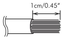
fig. 3
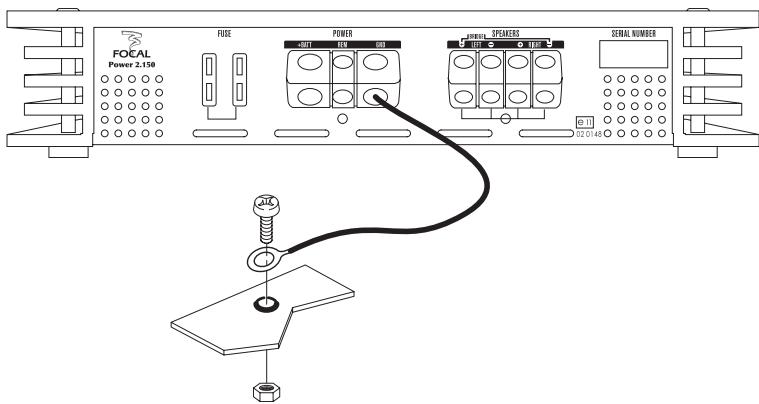
fig. 4
3.5 - You can now start the connection phase - i.e. connection of the audio signal (RCA), REMOTE, and loudspeaker cables. Connect the RCAs to the amplifier, making sure that the polarities are correct (i.e. INPUT Left = black or white, INPUT Right = red). Connect the other end of the RCAs to the car radio's RCA* outputs (Left = left; Right = right).
fig. 5
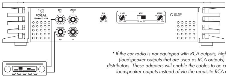
* If the car radio is not equipped with RCA outputs, high-level to low-level adapters (loudspeaker outputs that are used as RCA outputs) are available from all Focal distributors. These adapters will enable the cables to be connected via the car radio's loudspeaker outputs instead of via the requisite RCA outputs, which they replace.
Then connect the REMOTE cable to the amplifier (the REM terminal) - screw it in firmly. Connect the other end of the REMOTE cable to the car radio's REMOTE terminal.
Finally, connect the loudspeaker cables to the amplifier and make sure the polarities are correct.
Connect the REMOTE CONTROL cable (a remote control is supplied with the FP 1.800 and FP 5.500 model amplifiers) to the amplifier, and then put the remote control in its holder at the desired location.

WARNING
Focal amplifiers are not recommended for use with impedance levels of less than 2 (apart from the FP 1.800 model).
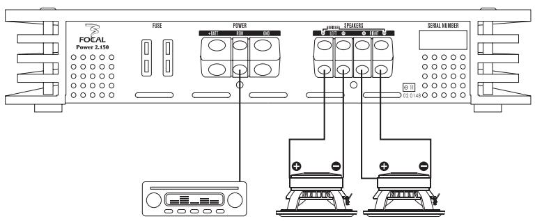
fig. 6
3.6 - Get the positive (+) power supply cable ready for connection to the amplifier by removing 1cm of the plastic coating from the end of it. Tin this part of the cable using a soldering iron and tin the wire. Insert the plastic-free tinned part of it in the amplifier's " + BATT" terminal, then secure the cable in place by screwing it in tightly.
WARNING
The cable that links the positive (+) terminal to the battery at the amplifier's "+" BATT" binding post terminal must ABSOLUTELY be fused (see current ratings listed in the table on page 19) not more than 40cm from the vehicle's battery. The connections on the fuse-holder must be fully insulated.
3.7.1 - You can now start the fuse-holder (the role of which is to make the system safe) installation phase. The fuse-holder must be connected on both sides to the positive (+) power supply cable. It has to be near the battery (i.e. 10cm - 40cm from the battery). Disassemble the fuse-holder, taking care to remove the fuse. Attach the base of the fuse-holder. Cut the red power supply cable at a distance of between 10cm and 40cm (maximum) from the battery. Retain the cable you do not use here, as it will be used later, to link the other end of the fuse-holder to the positive (+) terminal of the vehicle's battery. Strip 1cm of the cable end, then tin it. Screw the cable into the fuse-holder binding post terminal. Do not throw away the spare cable that is left over. Strip 1cm of the cable end, then tin it. Screw the cable into the other fuse-holder binding post terminal (fig. 7).
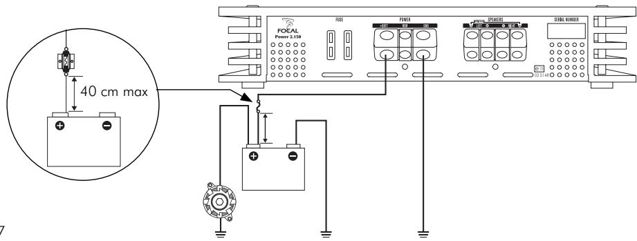
fig. 7
Note: The FP 5.500 amplifier use internal fuses (as opposed to other amplifiers witch have fuses on the rear panel). Replacing these components requires opening the bottom cover of the amplifier. Only a Focal dealer is authorized to change this component. Thank you for bringing the amplifier back to your dealer in order to place the fuse, so to avoid any risk of electric shock, product damage or avoidance of guarantee.
WARNING
Do not open the amplifier or undertake any modifications to the product. There is a risk of accident, fire or electric shock.
3.7.2 - THE FOLLOWING PROCEDURE IS INTENTED TO FOCAL DEALER ONLY. DO NOT CHANGE THE FUSE BY YOURSELF.
FP 5.500 fuse replacement procedure:
- Switch off the amplifier and the other components of the car audio system.
- Disconnect the positive terminal of the battery powering the amplifier.
- Unscrew the fixing screws of the amplifier.
- Turn the amplifier upside down, bear in mind that wires musn't get twisted or crushed.
- Unscrew the screws securing the bottom cover of the amplifier.
- Take the cover off.
-
Remove the blown fuses.
-
Insert the new fuses in the fuse holder. Make sure that the new fuse rating corresponds to the product specifications.
- Put the bottom cover back on and secure it with the screws then screw.
- Turn the amplifier back into position with its bottom facing the attachment surface.
- Screw in the fixing screws of the amplifier.
- Connect the positive terminal of the battery powering the amplifier.
3.8 - Tin the end of the power supply cable before you connect it to the battery's positive (+) terminal. Weld the end of the cable to the terminal lug that is going to be used for the battery's positive (+) terminal. Connect the terminal lug to the battery's positive terminal.
3.9 - Insert the fuse into the fuse-holder(s), and screw in tightly.
3.10 - Connect the loudspeaker cables to the right and left channel crossover networks, making sure that the polarities are the same (note: + = cable with a red border if you are using a Focal kit) as those used for standard cabling set-ups. Focal amplifiers can operate in bridged mode (see product specifications page 19) for amplifying subwoofoers. To do so, simply connect the positive (+) loudspeaker cable to the left channel's ("LEFT") positive (+) binding post terminal and connect the negative (-) loudspeaker cable to the right channel's ("RIGHT") negative (-) binding post terminal.
WARNING
If you are connecting several subwoofoers to a single output, check that the amplifier's impedance rating is compatible (p 19).
3.11 - The connection phase has now been completed. Now all you need to do is to check that you have the right power supply and verify that the overall set-up – car radio + amplifier + loudspeakers – works properly. Set all gains (both source gains and amplifier gains) to their minimum levels. Switch on the various parts of the system. Once you have switched on all of the parts, test the system at low sound level.
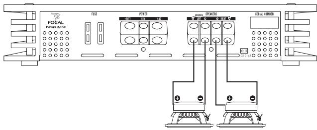
fig. 9
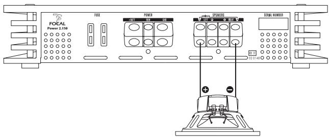
fig. 10
3.12 - Focal amplifiers can be interlinked to facilitate upgrades to the Car Audio system. If you want to create a system that uses several amplifiers, it is therefore possible to save time by not having to connect the source audio cable (from the car radio) to the amplifier again. You simply need to use the "LINE OUT" output on the first Focal amplifier you have installed and connect it to the "INPUT" connector on the new amplifier you are installing. The line level signal from the source will be forwarded directly to the newly-installed amplifier. The settings you have chosen for the first amplifier (GAIN, HI PASS, etc.) will not be duplicated to the line level signal (RCA) – this means that your amplification system will always be 100% reconfigurable.
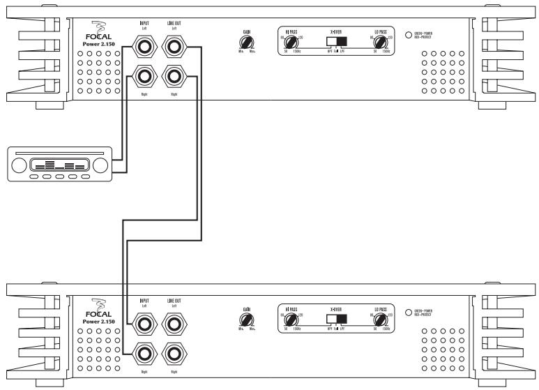
fig. 11
Focal Power 1.800 bridge mode
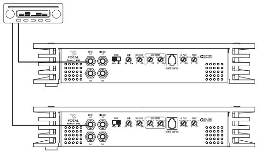
fig. 12. A
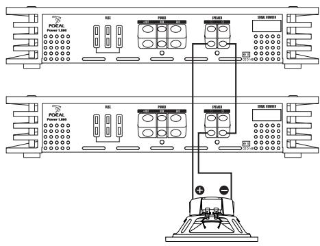
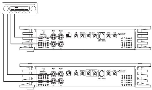
fig. 12. B
Focal Power 2.150 and Focal Power 2.75
Focal Power 4.75
Focal Power 1.800
Focal Power 5.500
Connections, features and controls
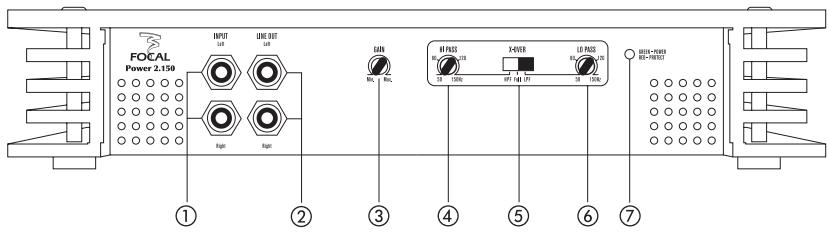
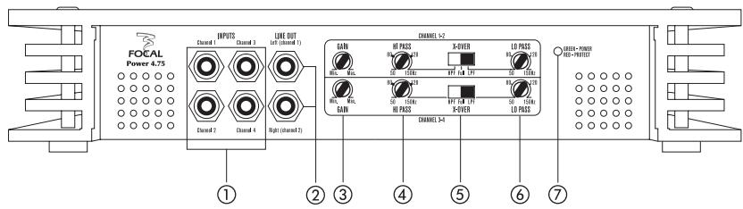
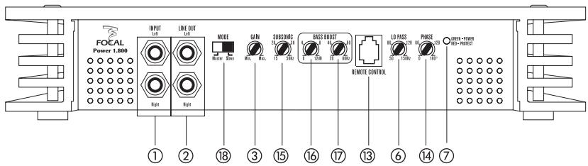
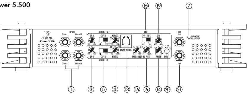
① INPUT(S): the RCA sockets are used for input of the line level signal.
NOTE: the RCA inputs on the FP 4.75 and FP 5.500 model amplifiers relate to channels 1, 2, 3 and 4.
② LINE OUT: the RCA sockets enable a second amplifier to be connected into an existing system, without having to install additional RCA cables to connect the front of a vehicle with an additional amplifier.
NOTE: the FP 5.500 amplifier system does not include a LINE OUT output.
③ GAIN: you can adjust the level of input signals to the amplifier using the GAIN potentiometer.
NOTE: increasing input gain does not mean more power, but rather more noise. Gains in voltage vary from 0.2V to 5V.
NOTE: the GAIN potentiometers on the FP 4.75 and FP 5.500 models can ONLY be used on channels 1, 2, 3, and 4. The GAIN potentiometers located at the top of control panels on the FP 4.75 and FP 5.500 amplifiers relate to channels 1 and 2, whereas those located at the bottom correspond to channels 3 and 4.
This potentiometer must be set depending on the level of the source (level of line output). Start by putting amplifier gain at its lowest level. Gradually increase the level (volume) of the source to 75% of maximum. Increase the amplifier gain level until the required listening volume is reached. Lower the level should sound distortion occur.
If you are using the amplifier in conjunction with one or more subwoofer, the "GAIN" control will enable you to set the levels of the subwoofer(s) in relation to that of sub-systems that are amplified by the source (i.e. the car radio, etc.) or by another amplifier. Set the source at a medium volume level, and then set amplifier gain in order to obtain consistent sound levels from kits/sub-systems and from the subwoofer(s).
④ HI PASS (high pass): the HI PASS potentiometer lets you set the HI PASS filter frequency. The value selected is the frequency above which the signal will be amplified.
NOTE: the FP 1.800 amplifier has a HI PASS filter called SUBSONIC.
NOTE: the HI PASS feature on the FP 4.75 and FP 5.500 amplifiers ONLY works on channels 1, 2, 3 and 4. The HI PASS potentiometers located at the top of control panels on the FP 4.75 and FP 5.500 amplifiers relate to channels 1 and 2, whereas those at the bottom correspond to channels 3 and 4.
Example: X-OVER in HPF position, HI PASS set to 80Hz : The full range kit connected to the amplifier will reproduce an amplified signal at 80Hz and above.
(5) X-OVER (filter mode): the X-OVER switch enables you to switch on either a high pass filter (a HPF), a low pass filter (an LPF) or to not activate any filter at all (Full mode)..
NOTE: the X-OVER switch located at the top of the control panel on the FP 4.75 amplifier relates to channels 1 and 2, whereas that at the bottom corresponds to channels 3 and 4.
NOTE: the FP 1.800 amplifier does not have an X-OVER switch.
NOTE: the X-OVER feature on the FP 5.500 amplifier ONLY works on channels 1, 2, 3 and 4. This X-OVER switch enables you to switch on, according to your requirements, a high pass filter (a HPF), or not to activate any filter (Full mode). The X-OVER switch located at the top of the control panel relates to channels 1 and 2; whereas the one at the bottom corresponds to channels 3 and 4.
⑥ LO PASS (low pass): the LO PASS potentiometer means that you can set the low pass filter frequency. The value selected is the frequency below which the signal will be amplified.
NOTE: the LO PASS potentiometer on the FP 4.75 model amplifier relates to channels 1, 2, 3 and 4. The LO PASS switch located at the top of the control panel relates to channels 1 and 2; whereas the one at the bottom corresponds to channels 3 and 4.
NOTE: the LO PASS feature on the FP 5.500 model amplifier may ONLY be activated using the SUB output.
This filter should only be used if the amplifier is connected to a subwoofer, but UNDER NO CIRCUMSTANCES WHATSOVER IF IT IS CONNECTED TO A FULL RANGE KIT. In that case it will enable you to set the frequency up to which the subwoofer will re-transcribe the audio signal.
Example : X-OVER in LPF position, LO PASS set at 80Hz : the subwoofer connected to the amplifier will re-transcribe the signal amplified, up to 80Hz
⑦ Status indicator: Status indicator: the indicator lets you know whether or not the amplifier is working properly. If the LED (light-emitting diode) indicator is green, your amplifier is switched on and operating normally. If the LED display light is red, your amplifier is being protected following some kind of malfunction - i.e. overheating, defective cabling, etc.
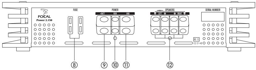
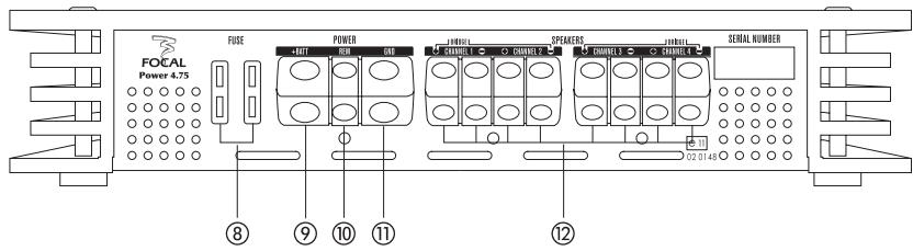
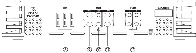
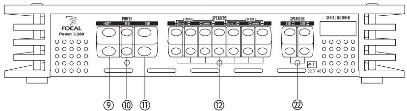
(8) FUSE: the FUSE connector is where the amplifier fuse(s) are positioned. When replacing fuses, ensure that the new fuse has exactly the same rating as the old one.
NOTE: the FP 5.500 amplifier has internal fuses. If your fuses need to be replace, please bring your amplifier back to your Focal dealer.
(9) + BATT : the +BATT power connector is used for the power supply cable which connects the amplifier to the battery's positive (+) terminal.
⑩ REM: the REM connector links the amplifier with the source (car radio) via a REM or REMOTE car radio output. This enables the automatic turn-on of the amplifier when powering on the source (car radio).
⑪ GND: the GND (ground) power connector receives the negative (-) cable ensuring the link between the amplifier and the vehicle's chassis.
⑫ SPEAKERS: the SPEAKERS' connectors link the amplifier and the loudspeakers' crossovers (or the loudspeakers in case of integral crossovers). It is IMPERATIVE to respect the polarities (+ amplifier → + crossover or + speaker / - amplifier → - crossover or - speaker).
NOTE: the SPEAKER output of the FP 1.800 amplifier is ONLY for the connection of one or several subwoofer(s).
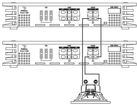
NOTE: When using two FP 1.800 connected together (the first amplifier is locked in Master position, while the second one is locked in Slave position), you must connect the negative speaker terminal of the Master amplifier to the negative speaker terminal of the Slave amplifier (Fig. 12. A and/or Fig. 12. B).
NOTE: When connecting a sub (or more than one sub in serial or in parallel) on two FP 1.800, you must connect the positive terminal of the subwoofer to the positive terminal of the Master amplifier and connect the negative terminal of the subwoofer to the positive terminal of the Slave amplifier (Fig. 12. A and/or Fig. 12. B).
NOTE: the SPEAKERS outputs of the FP 5.500 amplifier are ONLY for connecting coaxial, 2-way or 3-way kits. DO NOT CONNECT A SUBWOOFER to these outputs.
Connections and functions specific to the FP 1.800 and FP 5.500 amplifiers.
⑬ REMOTE CONTROL:
NOTE: DO NOT CONFUSE REMOTE AND REMOTE CONTROL. The REMOTE CONTROL output is for connecting the supplied remote control unit. This accessory enables your to remotely adjust the amplifier's gain.
NOTE: the REMOTE CONTROL (remote control) of the FP 5.500 amplifier ONLY works on the SUB output (subwoofer).
(4) PHASE: the PHASE potentiometer allows you to adjust the channel phase according to the installation.
NOTE: the PHASE control of the FP 5.500 amplifier is ONLY active on the SUB output (subwoofer).
SUBSONIC: the SUBSONIC potentiometer is ONLY the equivalent of a HI PASS filter for the subwoofer output of the amplifier (SPEAKER output for the FP 1.800 amplifiers, SPEAKERS Sub+ Sub- output for the FP 5.500 amplifier). The selected value defines the frequency from which the signal will be amplified. Activation of the filter can avoid distortion.
NOTE: the SUBSONIC filter of the FP 5.500 amplifier is actually an ON/OFF button. The cut-off frequency is 25Hz with a 24dB/octave roll-off.
BASS BOOST 0/12dB: the BASS BOOT 0/12dB potentiometer enables you to raise the level from 0 to 12dB over a frequency range which must be selected through the BASS BOOT 20/80Hz potentiometer (frequency selection ONLY available on the FP 1.800 amplifier).
NOTE: the BASS BOOT of the FP 5.500 amplifier is ONLY to be used on the SUB (subwoofer) output. The central frequency is 45Hz for a Q factor equal to 1.
Connections and functions specific to the FP 1.800 amplifier
BASS BOOST 20/80Hz: 20/80Hz: the BASS BOOT 20/80Hz potentiometer allows you to select the frequency band on which the level is to be raised through a BASS BOOST 0/12dB potentiometer. The BASS BOOT Q factor is equal to 1.
MODE: the MODE button allows you to define the situation of the amplifier when using two FP 1.800 amplifiers. The one used upstream within the system MUST be in the Master position, while the second should be in Slave position. The slave position automatically reverse the phase. The gain button is also out of use. The gain level is the same than the master amplifier gain level. When connecting two FP 1.800 together, you must do the same settings on the Master amplifier and on the Slave amplifier (SUBSONIC, BASS BOOST 0-12dB, BASS BOOST 20-80Hz, LO PASS and PHASE).
Connections and functions specific to the FP 5.500 amplifier
GAIN: the GAIN potentiometer enables you to raise the level of the incoming line level signal in the amplifier for the subwoofer ONLY. WARNING: increasing the input gain does not mean more power, but more noise. The voltage gain varies from 0.2V to 5V. This potentiometer should be adjusted at the same time as the source level (car radio volume).
20 INPUT: many sources (car radio) only have one single stereo output (i.e. a pair of RCA) to feed the line level signals to the amplifier. In order to power channels 1, 2, 3, 4 and SUB, you need a split RCA cable. In this case, the low, medium and high frequencies will be transmitted to inputs 1, 2, 3, 4 of the amplifier. The very low frequencies of the SUB channel will be transmitted via inputs 1 and 2, and the INPUT button will be positioned on CH 1/2 to send the very low frequencies towards the SUB channel, while maintaining control of the medium high frequencies on channels 1, 2, 3, 4.
SUB: the RCA inputs are intended to supply the low level (line level) signals of the source (car radio) towards the SUB channel of the amplifier (where the source is equipped with several outputs).
In order to optimise the overlap of frequency ranges reproduced by the subwoofer and the coaxial or 2-way kits, we advise you to adjust the frequency of the HI PASS filter or that of the LO PASS with an RTA (real-time analyser). Another possibility is to refer to the packaging of your kit or its user's manual. In the case of a Focal kit, the measurements supplied as frequency response take into account the installation of the kit inside a vehicle.
Tuning the FP 1.800 amplifier for SPL contests:
NOTE:
The following adjustments do not correspond to a "musical" use of the amplifier. What is sought here is the maximum sound pressure level without damaging the subwoofer/s.
The use of the FP 1.800 amplifier during SPL contests is an additional asset. The various adjustments available enable you to optimize the amplification for use in SPL contests. Tune the SUBSONIC filter to 50Hz . Position the BASS BOOST level at 12dB, then tune the BASS BOOST frequency to 60Hz . Adjust the LO PASS to 80Hz
Conditions of the Guarantee
In the event of a problem, firstly contact your Focal distributor.
The guarantee for France of all Focal material is for 1 year. In the event of faulty material, this should be sent at your cost in its original packaging to your distributor, who will analyse the equipment and determine the nature of the problem. If it is under guarantee, the equipment will be returned to you or replaced "post-paid".
Otherwise a quote for the repair job will be given to you. The guarantee does not cover damages caused by improper use of improper connection of the amplifier.
Outside France, Focal equipment is covered by a guarantee with local conditions which are set out locally by the official Focal distributor in each country, in accordance with local legislation.
TECHNICAL SPECIFICATIONS
| FP 2.75 | FP 2.150 | FP 4.75 | FP 5.500 | FP 1.800 | ||
| Nominal RMS power measured at 13.8V continuously @ 4Ω | 2x75W | 2x150W | 4x75W | 4x75W+1x200W | 1x400W | |
| Nominal RMS power measured at 13.8V continuously @ 2Ω | 2x100W | 2x200W | 4x100W | 4x100W+1x300W | 1x600W | |
| RMS bridged power measured at 13.8V continuously @ 4Ω | 1x200W | 1x400W | 2x200W | 2x200W+1x200W | - | |
| Nominal RMS power measured at 13.8V continuously @ 1Ω | - | - | - | - | 1x800W | |
| Signal/noise ratio | >100dB(A) | >100dB(A) | >100dB(A) | >100dB(A) | >100dB(A) | |
| Damping factor @ 4Ω | >500 | >500 | >200 | >200 | >200 | |
| Frequency response | 10Hz-35kHz | 10Hz-35kHz | 10Hz-35kHz | 10Hz-35kHz | 10Hz-300Hz | |
| Input impedance | 13kΩ | 13kΩ | 13kΩ | 13kΩ | 13kΩ | |
| Sensitivity | 0.2-5V | 0.2-5V | 0.2-5V | 0.2-5V | 0.2-5V | |
| High-pass filter | 50-150Hz(12dB/oc.) | 50-150Hz(12dB/oc.) | 50-150Hz(12dB/oc.) | 50-150Hz(12dB/oc.) | - | |
| Low-pass filter | 50-150Hz(12dB/oc.) | 50-150Hz(12dB/oc.) | 50-150Hz(12dB/oc.) | 50-150Hz(12dB/oc.) | 50-150Hz(24dB/oc.) | |
| Remote control | - | - | - | YES | YES | |
| Adjustable bass boost level | - | - | - | 0/+12dB | 0/+12dB | |
| Adjustable bass boost frequency | - | - | - | - | 20-80Hz | |
| Variable phase (SUB) | - | - | - | 0/180° | 0-180° | |
| Subsonic filter | - | - | - | 25Hz (24dB/oc.) | 15-50Hz(24dB/oc.) | |
| Maximum cross section of loudspeaker cables | 10mm27AWG | 10mm27AWG | 10mm27AWG | 10mm27AWG(sub) | 7mm28AWG(speakers) | 10mm27AWG |
| Maximum cross section of power cables | 25mm23AWG | 25mm23AWG | 25mm23AWG | 25mm23AWG | 25mm23AWG | |
| Idle current | 0.8A | 0.8A | 1A | 1A | 1A | |
| Fuse(s) | 1x40A | 2x40A | 2x40A | 4x30A | 3x30A | |
| Protections | Short-circuitDCOver-heatingClip limiterOvervoltagePolarity reversal | Short-circuitDCOver-heatingClip limiterOvervoltagePolarity reversal | Short-circuitDCOver-heatingClip limiterOvervoltagePolarity reversal | Short-circuitDCOver-heatingClip limiterOvervoltagePolarity reversal | Short-circuitDCOver-heatingClip limiterOvervoltagePolarity reversal | |
| Dimensions (HxLxD) | 50x230x280mm | 50x350x280mm | 50x350x280mm | 50x500x280mm | 50x320x280mm | |
1 The LED indicators on the top and on the side of the amplifier are off:
- Check that there is a DC voltage of 10.5 to 15.5V at the amplifier power supply connector.
- Check that there is a DC voltage of 10.5 to 15.5V at the battery positive terminal and at the remote switch-on cable (REMOTE). Check the quality of the connections at the two cables of the amplifier, the audio source, the battery and fuse holder Repair or replace if necessary.
- Check the fuse(s) of the battery's positive cable.
- Check the fuse(s) situated on the sides of the amplifier.
- Check that the ground connection is properly implemented on the vehicle's chassis, and that it is on a clean metal surface (without any traces of paint or varnish).
2 The LED indicator on the top of the amplifier is off, the indicator on the side of the amplifier is on and red:
- Switch off the amplifier and the source (car radio).
- Turn on the source (car radio) and the amplifier after waiting for its upper side to cool down.
- If the problem persists, go to step 3.
3 Verification of the amplifier's audio connections
- Check that the RCA input connections are properly connected both at the audio source and to the amplifier. Ensure that the cables are not twisted or broken.
4 The amplifier turns on then turns off
- Verify that no loudspeaker cable is in contact with the vehicle's body (ground point).
- Switch off the audio source and the amplifier. Disconnect the loudspeaker cables and test the loudspeakers with a multimeter adjusted to the impedance measurement to ensure they are working correctly.
- Touch the amplifier with care to check its temperature. If the temperature is high, the amplifier is in thermal protection mode and must cool down.
- Verify the voltage of the + BATT cable. If the voltage is over 15V or below 10.5V, refer to a specialist in car electrical systems.
5 No sound on one channel
- Check the connections of the amplifier end and at the audio source.
- Also check the balance (audio source), then check the loudspeakers with a multimeter in order to make sure there is no short-circuit.
6 Sound level is low
- Check the setting of the potentiometer (volume) of the audio source and the input sensibility of the amplifier (gain).
7 The amplifier stops after a long period of operation
- Check the colour of the LED indicator on the side. If it is red, the amplifier is likely in thermal shutdown. This is evidence of poor cooling due to an improper location or positioning of the amplifier.
- If cooling is ok, check the impedance of the loudspeakers to ensure that it is compatible with the amplifier's capabilities.
- If this is the case, make sure that the positive terminal of the vehicle's battery do supply a DC voltage comprised between 10.5V and 15V. Also check that the cable cross section is according to the recommendations of p. 7.
- Check that the fuse contained in the fuse holder situated near the vehicle's battery is suitable.
8 Noise increasing with accelerating vehicle
- This is a ground loop phenomenon. To verify if this noise is caused by an incorrect grounding, switch off the amplifier and the audio source, then remove the amplifier's RCA cables (ensure that they are shielded and are not touching the chassis once disconnected). Switch the amplifier and the audio source on.
- If the problem persists, it is a grounding problem. If it disappears, the problem is due to the RCA cables being either damaged or too close to the power cables. It is thus necessary to change and place the RCA cables opposite the power cables.
- In the event of a grounding problem, ensure that the ground cables are correctly connected and that the quality of the contacts is good (no paint or varnish on the grounding area.
Once all these verifications have been undertaken and if the amplifier still does not work, contact your nearest Focal distributor.
| Gain | ||||
| X-over 1-2 | ||||
| X-over 3-4 | ||||
| Hi-pass | ||||
| Lo-pass | ||||
| Subsonic | ||||
| Bass boost level | ||||
| Bass boost frequency | ||||
| Phase |
| Gain | ||||
| X-over 1-2 | ||||
| X-over 3-4 | ||||
| Hi-pass | ||||
| Lo-pass | ||||
| Subsonic | ||||
| Bass boost level | ||||
| Bass boost frequency | ||||
| Phase | ||||
| Lo-pass | ||||
| Subsonic | ||||
| Bass boost level | ||||
| Bass boost frequency | ||||
| Phase |
| Gain | ||||
| X-over 1-2 | ||||
| X-over 3-4 | ||||
| Hi-pass | ||||
| Lo-pass | ||||
| Subsonic | ||||
| Bass boost level | ||||
| Bass boost frequency | ||||
| Phase |
NOTICE AMPLIFICATEURS FOCAL POWER
AWG: American Wire Gauge
The Focal guarantee only applies if this page is returned to us within 10 days of purchase, to the following address:
Your complete address:
Your email address:
Details of your installation (brand, model):
Cassette:
CD:
Navigation:
Multimedia center:
DVD:
-
Loudspeakers:
-
CD-change:
Other elements:
Your decision for purchasing this Focal model was made according to:
Dealer's advice
□ Friend's advice
Visit to an exhibition, show
Press article
Listening in auditorium
□ Already own Focal products
Reliability / Quality
□ Documentation
Reputation
French produce
Guarantee
Quality / Price ratio
Design / Finishes
□ Other
Sound
In case of purchase of new equipment, what was your former amplifier?
Explain in a few words why you choose Focal...
Further comments:

Focal® is a registered trademark of Focal-JMlab® - www.focal-fr.com