
MP 400 - Amplifier PEAVEY - Free user manual and instructions
Find the device manual for free MP 400 PEAVEY in PDF.

| Product type | 4-channel powered mixer |
| Brand | PEAVEY |
| Model | MP 400 |
| Output power | 80 W RMS at 4 ohms, 55 W RMS at 8 ohms |
| Power supply | 150 W, 100/120/230 VAC, 50/60 Hz |
| Minimum speaker impedance | 4 ohms |
| Number of input channels | 4 |
| Input types per channel | XLR (low impedance) and 6.4 mm jack (high impedance) |
| Phantom power | +15 VDC on XLR inputs |
| Channel equalizer | Contour control (treble ±15 dB at 10 kHz) |
| Master equalizer | 3-band: bass (80 Hz), mid (1 kHz), treble (10 kHz), ±15 dB |
| Reverb | Internal reverb with channel and master control, footswitch (optional) |
| Outputs | Main 6.4 mm jack, Aux/Reverb 6.4 mm jack, two speaker outputs 6.4 mm jack |
| Aux input | 6.4 mm jack for line level signal |
| Frequency response | 20 Hz to 20 kHz (±3 dB) to speaker outputs |
| Distortion (THD) | Less than 0.009% at 1 kHz |
| Signal-to-noise ratio | Greater than 80 dB (mic to speaker) |
| Dynamic range | 95 dB |
| Safety | Electric shock risk, do not open, do not expose to rain or moisture |
| Maintenance and cleaning | Clean with a dry, soft cloth. Do not use abrasive products. |
| Repairability | Have repairs done by an authorized Peavey repair technician. No user-serviceable parts inside. |
| Optional accessories | Footswitch (model 5100) |
Frequently Asked Questions - MP 400 PEAVEY
User questions about MP 400 PEAVEY
0 question about this device. Answer the ones you know or ask your own.
Ask a new question about this device
Download the instructions for your Amplifier in PDF format for free! Find your manual MP 400 - PEAVEY and take your electronic device back in hand. On this page are published all the documents necessary for the use of your device. MP 400 by PEAVEY.
USER MANUAL MP 400 PEAVEY
Intended to alert the user to the presence of uninsulated "dangerous voltage" within the product's enclosure that may be of sufficient magnitude to constitute a risk of electric shock to persons.

Intended to alert the user of the presence of important operating and maintenance (servicing) instructions in the literature accompanying the product.
CAUTION: Risk of electrical shock — DO NOT OPEN!
CAUTION: To reduce the risk of electric shock, do not remove cover. No user serviceable parts inside. Refer servicing to qualified service personnel.
WARNING: To prevent electrical shock or fire hazard, do not expose this appliance to rain or moisture. Before using this appliance, read the operating guide for further warnings.

Thank you for purchasing the Peavey MP™ 400! The MP™ 400 is a four-channel, powered mixer packed into an amazing compact package. Featuring only the essential requirements for a sound reinforcement mixer, the MP 400 is a breeze to operate and a joy to own. Quality semiconductor components lend a hand to achieve the excellent audio characteristics and reliable service that has made the MP Series Mixer so well known.
The MP 400 boasts four discrete channels, each with high and low impedance inputs, a Contour high frequency EQ control, and Reverb and Level controls. The master section offers a three-band equalizer, Master Level and Reverb controls, 1/4 Main and Reverb/Aux Outputs, Aux Input, and Remote Switch Input.
The following guide explains the MP 400 features and the proper operation of each. Refer to the diagrams in each section to locate each feature by its designated number. Throughout this guide, related features will sometimes refer you to another feature using this number system. Let's begin by listing the main features of the MP 400.
FEATURES:
- Four total input channels
- Reverb control on each channel
- Contour high frequency equalizer on each channel
- 1/4" and XLR inputs on each input channel
1/4" Main Output
1/4" Aux/Reverb Output
1/4" Aux Input
1/4" Remote Switch for reverb defeat - Master Three-band Equalizer
- Master Level and Reverb controls
- 80 W power amp
POWER
This section describes the proper application of AC power to your MP 400. To insure the safety of you and your MP 400, please pay close attention to any designated cautions.
REAR PANEL
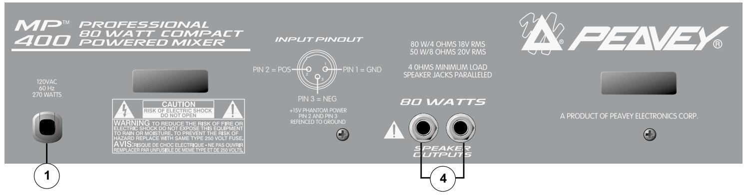
1. IEC POWER SOCKET:
With the Power Switch (#2) in the off (O) position, plug the power cord into this connector prior to plugging it into your AC power source. Always insure that proper grounding practices are utilized. Damage to the equipment may occur if improper line voltage is used (see voltage marking on unit). Never remove or cut the ground pin of the line cord plug.
NOTE: FOR UK ONLY
As the colors of the wires in the mains lead of this apparatus may not correspond with the colored markings identifying the terminals in your plug, proceed as follows: (1) The wire which is colored green and yellow must be connected to the terminal which is marked by the letter E, or by the earth symbol, or colored green or green and yellow. (2) The wire which is colored blue must be connected to the terminal which is marked with the letter N, or the color black. (3) The wire which is colored brown must be connected to the terminal which is marked with the letter L or color red.
2. POWER SWITCH (See front panel diagram next page)
Place this switch in the "ON" position to turn the unit on.
3. POWER LED (See front panel diagram next page)
Illuminates when AC power is being supplied to the mixer.
SPEAKER CONNECTIONS
This section will help you locate the two speaker output jacks on the rear of your MP 400.

WARNING: NEVER ALLOW YOUR TOTAL SPEAKER IMPEDANCE TO DROP BELOW THE MINIMUM IMPEDANCE OF 4 OHMS.
4. SPEAKER OUTPUTS
Two parallel 1/4" jacks are provided at the output of the power amplifier for ease of speaker connection. Minimum speaker impedance (min. load) is 4 ohms.
CHANNEL FEATURES (CHANNELS 1-4)
The following section describes channels 1-4. Each of these input channels is identical.
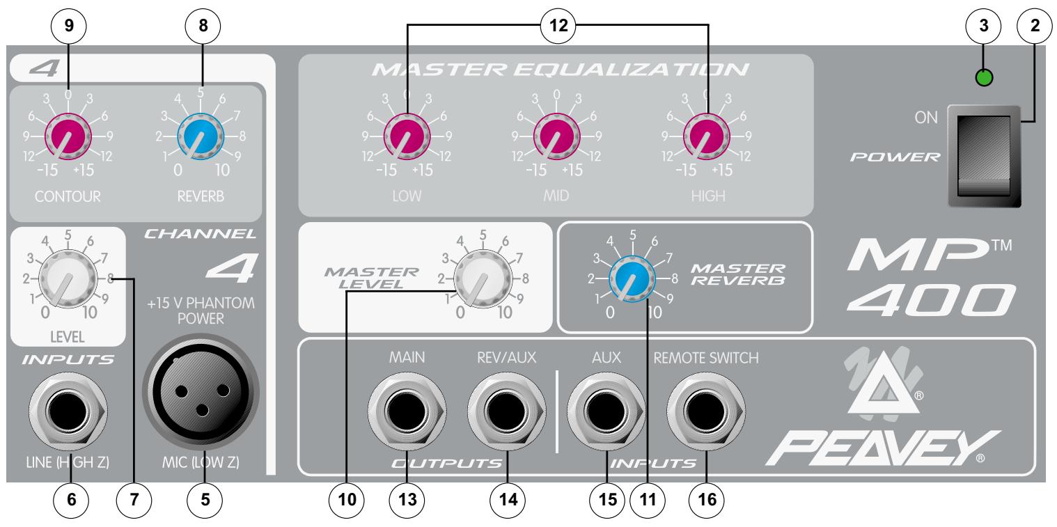
5. MIC (LOW Z) INPUT
XLR balanced low impedance channel input optimized for a microphone or other low impedance source. Pin 2 is the positive input. This connector has +15V phantom power supply on Pins 2 and 3 at all times (Pin 1 is the ground reference).

WARNING: BECAUSE THE LOW-Z INPUTS HAVE PHANTOM POWER, ONLY CONNECT MICROPHONES OR PRODUCTS WITH A BALANCED OUTPUT TO PREVENT DAMAGE. IF YOU ARE UNSURE, PLEASE CHECK THE PRODUCT'S OPERATING INSTRUCTIONS.
6. LINE (HIGH Z) INPUT
1/4" unbalanced input that accepts line level sources equipped with a 1/4" plug (TS). The two inputs (XLR and 1/4") cannot be used simultaneously.
7. LEVEL
Sets the level of the individual channel in the mix.
8. REVERB
Sets the level of the internal reverb for the channel and must be used in conjunction with the master reverb level. It is post gain and will be affected by the LEVEL (7) adjustment. The Reverb/Aux control also determines the level of signal sent to the Effects Output (14).
9. CONTOUR
A shelving type of active tone control that varies the treble frequency level ± 15 dB at 10kHz . It is designed to remove noise or to add brilliance to the signal, depending on the quality of the source.
MASTER FEATURES
10. MASTER LEVEL CONTROL
Controls the overall volume level of the system.
11. MASTER REVERB CONTROL
Controls the amount of reverb that will be heard in the main mix.
Provides ± 15 dB equalization at each center frequency. EQ boost is obtained by moving a particular EQ band's control above the "0" position. EQ cut is obtained by moving a particular EQ band's control below the "0" position. The following list describes each EQ control and its center frequency.
Low - shelving type - 80 Hz
Mid - peak type - 1 kHz
High - shelving type - 10 kHz
OPERATION NOTE: This equalizer is designed to provide room equalization, feedback control and system tone control. No amount of equalization will correct the response curve of a poor loudspeaker. Always begin with all controls in the "0" position and avoid excessively cutting large segments of the audio passband, which would limit the system's dynamic range.
13. MAIN OUTPUT
1/4" unbalanced output that can be used as a source for an external amplifier/speaker system feed to other mixers or a tape deck.
14. REVERB/AUX OUTPUT
Plugging into this mono (TS) 1/4 output allows you to utilize external effects devices. In order to return the signal from the external effects unit, use the Aux Input (15). Simply turn the Reverb Master down to defeat the Internal Reverb if desired.
15. AUX INPUT
Use this mono 1/4" (TS) input to insert a line-level signal into the main mix. This signal can originate from a variety of sources including instrument/mic preamps, external effects (see #14), and even an additional sub mixer. This input bypasses the reverb and can be controlled by the Master EQ and Level.
16. REVERB FOOTSWITCH
Provided for connection of the optional remote footswitch (5100). The footswitch is used to activate/defeat the reverb.
MP™ 400 SPECIFICATIONS
Note: All specifications are typical unless otherwise noted.
0 dBV = 1 Volt RMS
0 dBu = .778 Volts RMS
All specs are referenced to nominal output level (0 dBV) unless otherwise noted.
All measurements are wideband 20Hz to 20kHz unless otherwise noted.
All control settings are nominal (50% rotation) unless otherwise noted.
CHANNEL:
Equivalent Input Noise
-116 dBV @ 40 dB Max Gain
Frequency Response:
(To Speaker Outputs)
±3 dB 20 Hz to 20 kHz
Distortion: @ (1 kHz):
Less than .009%
Input Impedance:
Low Z Bal. 2K ohms
1/4" Mic Input 22K ohms
CHANNEL EQ:
Contour EQ:
±15 dB @ 10 kHz Minimum
Center Detent flat ±2 dB
Nominal Channel Gain:
Line = 0 dB
Low Z = 30 dB
Maximum Channel Gain:
Low Z = 50 dB
Line = 19 dB
Nominal Input Level:
Low Z = -30 dB
Line = 0 dB
Minimum Input Level:
Low Z = -50 dB
Line = -19 dB
Maximum Input Level:
Low Z =-11 dB
Line = +28 dB
Phantom Power:
+15 VDC
MASTER:
Gain
Main: = 10 dB (variable)
High EQ:
± 15 dB @ 12 kHz Minimum
Center Detent flat ±2 dB
Mid EQ:
±15dB@1kHz Minimum
Center Detent flat ±2 dB
Low EQ:
±15dB@60HZ Minimum
Center Detent flat ±2 dB
Maximum Output Level:
Main: = +18 dBV (8.0 V RMS)
Effects: = +18 dBV (8.0 V RMS)
Nominal Headroom:
Main: = 18 dB
Effects: = 18 dB
Output Impedance:
Main: = 100 ohms
Effects: = 100 ohms
Output Noise:
Residual: -95
(Master Level Down)
Bus: -93
(Master Nominal, All Channel Level Full CCW, Reverb Level Down)
Nominal: -78
(All Controls Nominal, Low Z Input Terminated 150 Ohms)
Signal to noise ratio:
Microphone input to speaker output (>80dB)
Frequency Response: 20Hz to 20kHz
SYSTEM DYNAMIC RANGE:
95 dB
POWER AMP SECTION:
Frequency Response:
+0, -3 dB, 30 Hz to 28 kHz @ Rated Power
RATED POWER AND LOAD:
80 W RMS into 4 ohms
55 W RMS into 8 ohms
THD less than .5% Mic input to speaker output 1 kHz at rated power. Speaker system Impedance: 4 ohms minimum.
Power Requirements:
150W @ 100V, 120V, 230 VAC 50/60 Hz.
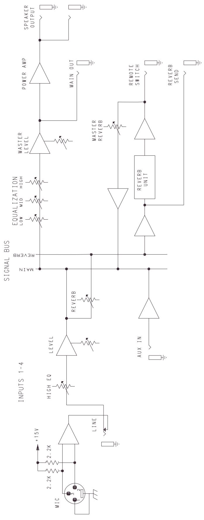
MP 400 BLOCK DIAGRAM
DEUTSCH
MP™ 400
Power-Mixer
Low - shelving type - 80 Hz
Mid - peak type - 1 kHz
High - shelving type – 10 kHz
±3 dB 20 Hz a 20 kHz
±15 dB @ 10 kHz Minimo
Centro plano ±2 dB
Ganancia Nominal de Canal:
Linea = 0 dB
Low Z = 30 dB
±15 dB @ 12 kHz Minimo:
Centro Plano ±2 dB
EQ Medio:
±15 dB @ 1 kHz Minimo:
Centro Plano ±2 dB
EQ Grave:
±15 dB @ 60 HZ Minimo:
Centro Plano ±2 dB
Nivel de Salida Maximo:
Main: = +18 dBV (8.0 V RMS)
Effectos: = +18 dBV (8.0 V RMS)
Umbral Nominal:
Main: = 18 dB
Effectos: = 18 dB
Effective Date: July 1, 1998
What This Warranty Covers
Your Peavey Warranty covers defects in material and workmanship in Peavey products purchased and serviced in the U.S.A. and Canada.
What This Warranty Does Not Cover
The Warranty does not cover: (1) damage caused by accident, misuse, abuse, improper installation or operation, rental, product modification or neglect; (2) damage occurring during shipment; (3) damage caused by repair or service performed by persons not authorized by Peavey; (4) products on which the serial number has been altered, defaced or removed; (5) products not purchased from an Authorized Peavey Dealer.
Who This Warranty Protects
This Warranty protects only the original retail purchaser of the product.
How Long This Warranty Lasts
The Warranty begins on the date of purchase by the original retail purchaser. The duration of the Warranty is as follows:
| Product Category | Duration |
| Guitars/Basses, Amplifiers, Pre-Amplifiers, Mixers, Electronic Crossovers and Equalizers | 2 years * (+ 3 years) |
| Drums | 2 years * (+ 1 year) |
| Enclosures | 3 years * (+ 2 years) |
| Digital Effect Devices and Keyboard and MIDI Controllers | 1 year * (+ 1 year) |
| Microphones | 2 years |
| Speaker Components (incl. speakers, baskets, drivers, diaphragm replacement kits and passive crossovers) and all Accessories | 1 year |
| Tubes and Meters | 90 days |
[denotes additional warranty period applicable if optional Warranty Registration Card is completed and returned to Peavey by original retail purchaser within 90 days of purchase.]
What Peavey Will Do
We will repair or replace (at Peavey's discretion) products covered by warranty at no charge for labor or materials. If the product or component must be shipped to Peavey for warranty service, the consumer must pay initial shipping charges. If the repairs are covered by warranty, Peavey will pay the return shipping charges.
How To Get Warranty Service
(1) Take the defective item and your sales receipt or other proof of date of purchase to your Authorized Peavey Dealer or Authorized Peavey Service Center.
OR
(2) Ship the defective item, prepaid, to Peavey Electronics Corporation, International Service Center, 412 Highway 11 & 80 East, Meridian, MS 39301 or Peavey Canada Ltd., 95 Shields Court, Markham, Ontario, Canada L3R 9T5. Include a detailed description of the problem, together with a copy of your sales receipt or other proof of date of purchase as evidence of warranty coverage. Also provide a complete return address.
Limitation of Implied Warranties
ANY IMPLIED WARRANTY, INCLUDING WARRANTYES OF MERCHANTABILITY AND FITNESS FOR A PARTICULAR PURPOSE, ARE LIMITED IN DURATION TO THE LENGTH OF THIS WARRANTY.
Some states do not allow limitations on how long an implied warranty lasts, so the above limitation may not apply to you.
Exclusions of Damages
PEAVEY'S LIABILITY FOR ANY DEFECTIVE PRODUCT IS LIMITED TO THE REPAIR OR REPLACEMENT OF THE PRODUCT, AT PEAVEY'S OPTION. IF WE ELECT TO REPLACE THE PRODUCT, THE REPLACEMENT MAY BE A RECONDITIONED UNIT. PEAVEY SHALL NOT BE LIABLE FOR DAMAGES BASED ON INCONVENIENCE, LOSS OF USE, LOST PROFITS, LOST SAVINGS, DAMAGE TO ANY OTHER EQUIPMENT OR OTHER ITEMS AT THE SITE OF USE, OR ANY OTHER DAMAGES WHETHER INCIDENTAL, CONSEQUENTIAL OR OTHERWISE, EVEN IF PEAVEY HAS BEEN ADVISED OF THE POSSIBILITY OF SUCH DAMAGES.
Some states do not allow the exclusion or limitation of incidental or consequential damages, so the above limitation or exclusion may not apply to you.
This Warranty gives you specific legal rights, and you may also have other rights which vary from state to state.
If you have any questions about this warranty or service received or if you need assistance in locating an Authorized Service Center, please contact the Peavey International Service Center at (601) 483-5365 / Peavey Canada Ltd. at (905) 475-2578.
Features and specifications subject to change without notice.
IMPORTANT SAFETY INSTRUCTIONS
WARNING: When using electric products, basic cautions should always be followed, including the following:
- Read these instructions.
- Keep these instructions.
- Heed all warnings.
- Follow all instructions.
- Do not use this apparatus near water. For example, near or in a bathtub, swimming pool, sink, wet basement, etc.
- Clean only with a damp cloth.
- Do not block any of the ventilation openings. Install in accordance with manufacturer's instructions. It should not be placed flat against a wall or placed in a built-in enclosure that will impede the flow of cooling air.
- Do not install near any heat sources such as radiators, heat registers, stoves or other apparatus (including amplifiers) that produce heat.
- Do not defeat the safety purpose of the polarized or grounding-type plug. A polarized plug has two blades with one wider than the other. A grounding type plug has two blades and a third grounding plug. The wide blade or third prong is provided for your safety. When the provided plug does not fit into your inlet, consult an electrician for replacement of the obsolete outlet. Never break off the grounding. Write for our free booklet "Shock Hazard and Grounding". Connect only to a power supply of the type marked on the unit adjacent to the power supply cord.
- Protect the power cord from being walked on or pinched, particularly at plugs, convenience receptacles, and the point they exit from the apparatus.
- Only use attachments/accessories provided by the manufacturer.
- Use only with a cart, stand, tripod, bracket, or table specified by the manufacturer, or sold with the apparatus. When a cart is used, use caution when moving the cart/apparatus combination to avoid injury from tip-over.
- Unplug this apparatus during lightning storms or when unused for long periods of time.
- Refer all servicing to qualified service personnel. Servicing is required when the apparatus has been damaged in any way, such as power-supply cord or plug is damaged, liquid has been spilled or objects have fallen into the apparatus, the apparatus has been exposed to rain or moisture, does not operate normally, or has been dropped.
- If this product is to be mounted in an equipment rack, rear support should be provided.
- Exposure to extremely high noise levels may cause a permanent hearing loss. Individuals vary considerably in susceptibility to noise-induced hearing loss, but nearly everyone will lose some hearing if exposed to sufficiently intense noise for a sufficient time. The U.S. Government's Occupational and Health Administration (OSHA) has specified the following permissible noise level exposures:
| Duration Per Day In Hours | Sound Level dBA, Slow Response |
| 8 | 90 |
| 6 | 92 |
| 4 | 95 |
| 3 | 97 |
| 2 | 100 |
| 1 1/2 | 102 |
| 1 | 105 |
| 1/2 | 110 |
| 1/4 or less | 115 |
According to OSHA, any exposure in excess of the above permissible limits could result in some hearing loss. Ear plugs or protectors to the ear canals or over the ears must be worn when operating this amplification system in order to prevent a permanent hearing loss, if exposure is in excess of the limits as set forth above. To ensure against potentially dangerous exposure to high sound pressure levels, it is recommended that all persons exposed to equipment capable of producing high sound pressure levels such as this amplification system be protected by hearing protectors while this unit is in operation.
SAVE THESE INSTRUCTIONS!

PEAVEY
Features and specifications subject to change without notice.
Peavey Electronics Corporation • 711 A Street • Meridian • MS • 39301 (601) 483-5365 • FAX (601) 486-1278 • www.peavey.com


- FEATURES:
- POWER
- REAR PANEL
- IEC POWER SOCKET:
- NOTE: FOR UK ONLY
- POWER SWITCH (See front panel diagram next page)
- POWER LED (See front panel diagram next page)
- SPEAKER CONNECTIONS
- WARNING: NEVER ALLOW YOUR TOTAL SPEAKER IMPEDANCE TO DROP BELOW THE MINIMUM IMPEDANCE OF 4 OHMS.
- SPEAKER OUTPUTS
- CHANNEL FEATURES (CHANNELS 1-4)
- MIC (LOW Z) INPUT
- LINE (HIGH Z) INPUT
- LEVEL
- REVERB
- CONTOUR
- MASTER FEATURES
- MASTER LEVEL CONTROL
- MASTER REVERB CONTROL
- MAIN OUTPUT
- REVERB/AUX OUTPUT
- AUX INPUT
- REVERB FOOTSWITCH
- MP™ 400 SPECIFICATIONS
- CHANNEL:
- Equivalent Input Noise
- Frequency Response:
- Distortion: @ (1 kHz):
- Input Impedance:
- CHANNEL EQ:
- Contour EQ:
- Nominal Channel Gain:
- Maximum Channel Gain:
- Nominal Input Level:
- Minimum Input Level:
- Maximum Input Level:
- Phantom Power:
- MASTER:
- Gain
- High EQ:
- Mid EQ:
- Low EQ:
- Maximum Output Level:
- Nominal Headroom:
- Output Impedance:
- Output Noise:
- Residual: -95
- Signal to noise ratio:
- SYSTEM DYNAMIC RANGE:
- POWER AMP SECTION:
- RATED POWER AND LOAD:
- Power Requirements:
- DEUTSCH
- MP™ 400
- Power-Mixer
- Ganancia Nominal de Canal:
- EQ Medio:
- EQ Grave:
- Nivel de Salida Maximo:
- Umbral Nominal:
- What This Warranty Covers
- What This Warranty Does Not Cover
- Who This Warranty Protects
- How Long This Warranty Lasts
- What Peavey Will Do
- How To Get Warranty Service
- OR
- Limitation of Implied Warranties
- Exclusions of Damages
- IMPORTANT SAFETY INSTRUCTIONS
- SAVE THESE INSTRUCTIONS!
Brand : PEAVEY
Model : MP 400
Category : Amplifier