
CKd 608 - Amplifier PEAVEY - Free user manual and instructions
Find the device manual for free CKd 608 PEAVEY in PDF.

| Product Type | Power Processing Amplifier |
| Number of Channels | 8 |
| Amplifier Class | Class D |
| Rated Power (4 Ohms, 1 kHz, single channel) | 660 W per channel at <0.05% THD |
| Rated Power (70.7V, 1 kHz, single channel) | 660 W per channel at <0.05% THD |
| Rated Power (100V, 1 kHz, single channel) | 660 W per channel at <0.025% THD |
| Minimum Load Impedance (Low Z mode) | 4 Ohms |
| Frequency Response | 10 Hz – 20 kHz, 0 dB to +0.5 dB (1 W, 8 Ohms) |
| Input Sensitivity (Low Z) | 1.25 V (4 Ohms), 1.77 V (8 Ohms) at 1 kHz |
| Input Impedance | 20 kOhms balanced, 10 kOhms unbalanced |
| Voltage Gain (Low Z) | x40 (32 dB) |
| Dimensions (H x W x D) | 3.48" x 19" x 20.30" (8.84 cm x 48.26 cm x 51.56 cm) |
| Net Weight | 23.4 lbs (10.60 kg) |
| Power Requirements | 120 VAC 60 Hz or 230 VAC 50 Hz |
| Idle Power Consumption | 180 W (350 VA) |
| Cooling Method | Temperature-dependent variable speed 80 mm DC fan |
| Protection Features | TourClass: ACL, IGM, AutoRamp, DC, Overcurrent, Thermal, Short Circuit, Load monitoring |
| Input Connectors | 8 x 3-pin Euro-style detachable terminal blocks |
| Output Connectors | 4 x 4-position barrier strip terminal blocks (screw terminals) |
| Module Bay | For optional NexSys network modules (NxDante8 or NxCobraNet8) |
| Rack Space | 2 EIA rack units |
Frequently Asked Questions - CKd 608 PEAVEY
User questions about CKd 608 PEAVEY
0 question about this device. Answer the ones you know or ask your own.
Ask a new question about this device
Download the instructions for your Amplifier in PDF format for free! Find your manual CKd 608 - PEAVEY and take your electronic device back in hand. On this page are published all the documents necessary for the use of your device. CKd 608 by PEAVEY.
USER MANUAL CKd 608 PEAVEY


FCC/ICES Compliance Statement
This device complies with Part 15 of the FCC rules and Industry Canada license-exempt RSS Standard(s). Operation is subject to the following two conditions: (1) this device may not cause harmful interference, and (2) this device must accept any interference received, that may cause undesired operation.
Warning: Changes or modifications to the equipment not approved by Peavey Electronics Corp. can void the user's authority to use the equipment.
Note – This equipment has been tested and found to comply with the limits for a Class B digital device, pursuant to Part 15 of the FCC Rules. These limits are designed to provide reasonable protection against harmful interference in a residential installation. This equipment generates, uses, and can radiate radio frequency energy and, if not installed and used in accordance with the instructions, may cause harmful interference to radio communications. However, there is no guarantee that interference will not occur in a particular installation. If this equipment does cause harmful interference to radio or television reception, which can be determined by turning the equipment off and on, the user is encouraged to try and correct the interference by one or more of the following measures.
- Reorient or relocate the receiving antenna.
- Increase the separation between the equipment and receivers.
- Connect the equipment into an outlet on a circuit different from that to which the receiver is connected.
- Consult the dealer or an experienced radio/TV technician for help.
Caution
The equipment complies with FCC radiation exposure limits set forth for an uncontrolled environment.

1 Save the carton and packing material even if the equipment has arrived in good condition. Should you ever need to ship the unit, use only the original factory packing.
2 Read all documentation before operating your equipment. Retain all documentation for future reference.
3 Follow all instructions printed on unit chassis for proper operation.
4 Do not spill water or other liquids into or on the unit, or operate the unit while standing in liquid.
5 Make sure power outlets conform to the power requirements listed on the back of the unit.
6 Do not use the unit if the electrical power cord is frayed or broken. The power supply cords should be routed so that they are not likely to be walked on or pinched by items placed upon or against them, paying particular attention to cords and plugs, convenience receptacles, and the point where they exit from the appliance.
7 Always operate the unit with the AC ground wire connected to the electrical system ground. Precautions should be taken so that the means of grounding of a piece of equipment is not defeated.
8 Mains voltage must be correct and the same as that printed on the rear of the unit. Damage caused by connection to improper AC voltage is not covered by any warranty.
9 Have gain controls on amplifiers turned down during power-up to prevent speaker damage if there are high signal levels at the inputs.
0 Power down & disconnect units from mains voltage before making connections.
Never hold a power switch in the "ON" position if it won't stay there itself!
Do not use the unit near stoves, heat registers, radiators, or other heat producing devices.
Do not block fan intake or exhaust ports. Do not operate equipment on a surface or in an environment which may impede the normal flow of air around the unit, such as a bed, rug, weather-sheet, carpet, or completely enclosed rack. If the unit is used in an extremely dusty or smoky environment, the unit should be periodically “blown free” of foreign matter.
Do not remove the cover. Removing the cover will expose you to potentially dangerous voltages. There are no user serviceable parts inside.
Connecting amplifier outputs to oscilloscopes or other test equipment while the amplifier is in bridged mode may damage both the amplifier and test equipment!
§ Do not drive the inputs with a signal level greater than that required to drive equipment to full output.
Do not connect the inputs / outputs of amplifiers or consoles to any other voltage source, such as a battery, mains source, or power supply, regardless of whether the amplifier or console is turned on or off.
f Do not run the output of any amplifier channel back into another channel's input. Do not parallel- or series-connect an amplifier output with any other amplifier output. Crest Audio is not responsible for damage to loudspeakers for any reason.
f Do not ground any + ("hot") terminal. Never connect a + ("hot") output to ground or to another + ("hot") output!
a Non-use periods. The power cord of equipment should be unplugged from the outlet when left unused for a long period of time.
Service Information
Equipment should be serviced by qualified service personnel when:
A. The power supply cord or the plug has been damaged;
B. Objects have fallen, or liquid has been spilled into the equipment;
c. The equipment has been exposed to rain;
D. The equipment does not appear to operate normally, or exhibits a marked change in performance;
E. The equipment has been dropped, or the enclosure damaged.
To obtain service,
contact your nearest Crest Audio Service Center, Distributor, Dealer, or Crest Audio at (866) 812-7378 (USA). This symbol is used to alert

This symbol is used to alert the operator to follow important operating procedures and precautions detailed in documentation.

This symbol is used to warn operators that uninsulated "dangerous voltages" are present within the equipment enclosure that may pose a risk of electric shock.
WARNING
THE ON/OFF SWITCH IN THIS APPARATUS DOES NOT BREAK BOTH SIDES OF THE MAINS. HAZARDOUS ENERGY MAY BE PRESENT INSIDE THE ENCLOSURE WHEN THE POWER SWITCH IS IN THE OFF POSITION.
Introduction
Congratulations on your purchase of a Crest Audio CKd family of Power Processing amplifiers. Please read this manual carefully (especially the "Important Precautions" section located inside the front cover) as it contains information vital to the safe operation of the amplifier. Also, please fill out and return the enclosed product registration card. The CKd Series of four and eight channel Power Processing amplifiers represent new levels of value and flexibility never before offered to the contracting market. CKd Series amps are specially designed to independently drive low impedance speaker loads and/or provide directly coupled 70.7 or 100 volt outputs on a per channel basis. This amplifier covers almost every conceivable installed or distributed sound power requirement. By combining legendary Crest performance with a plug-in module bay located on the rear panel, these amplifiers can become very sophisticated audio processors. The CKd Series is everything that you expect from Crest Audio. They are ruggedly built from high quality components, intelligently laid out, and possess comprehensive protection features. After-sale support is considered paramount at Crest Audio. For any assistance in the set-up or operation of this product please call Crest Audio's Customer Service department or your local Crest Audio representative. Should you have any problems at all, or suggestions that may help us improve our products or service, please contact us. We encourage your participation in Crest's future. (See back cover for contact info) Crest Audio may also be contacted on the World Wide Web at: http://www.crestaudio.com.
CKd Series Amplifier Features
- Two separate power supplies for amplifier and Nx Module Bay. High Current Amplifier power supply has front panel breaker.
- Four and eight-channel versions available utilizing the latest high efficiency class D topology.
- Individual channels may be selected as low impedance, 70 volt direct or 100V direct output.
- Tour Class® protection–ACL, IGM, AutoRamp, DC, OC, Thermal, Load, etc.
- Advanced limiting with thermal and performance parameters for maximum 'up-time' and sound quality.
- Front and rear panel LED indicators for amplifier status.
- Variable-speed fan with front to side ventilation.
- Sequential turn-on using contact closures.
- Mini Euro-style audio input connectors.
- Barrier strip amplifier output connections.
- 70Hz, 3 pole, high pass filter on each channel automatically engaged in 70V or 100V modes and disengaged in Low Z mode. Other options are available under software control.
- One controlled-voltage input per channel standard which defaults to channel gain through a 1K pot.
- Module bay provided for Nx module bay accessories for full amplifier control and monitoring via NexSys® software or MediaMatrix® product and digital audio distribution.
For your safety, read the important precautions section, as well as input, output, and power connection sections.


Installation
Getting Started
This section covers the basics for setting up CKd amps. Refer to this section in order to get the amplifier up and running quickly. Pay special attention to the Requirements and Considerations section. It contains important information concerning the operating conditions necessary to operate the CKd in a safe and stable fashion. Also be sure to refer to the Precautions page at the front of this manual for additional safety warnings.
Unpacking
Upon unpacking, inspect the amplifier. If you find any damage, notify your supplier immediately. Only the consignee may institute a claim with the carrier for damage incurred during shipping. Be sure to save the carton and all packing materials. Should you ever need to ship the unit back to Crest Audio, one of its offices, service centers, or the supplier, use only the original factory packing. If the shipping carton is unavailable, contact Crest to obtain a replacement.
Installation and Mounting
Crest Audio CKd Power Processing amplifiers are configured to a standard set-up at the factory. They are functional and ready to use 'out of the box.' All controls and input/output connections are clearly labeled. Units are shipped either with a network module or blank panel over the module bay.
To Set The Amplifier Up For Basic Usage:
- Rack mount the amplifier, remembering to allow for adequate access and cooling space. For more information, see the section titled Cooling Requirements in this section.
- Make input connections to the mini Euroblock connector inputs. Make the connections to all inputs for normal operation. Refer to Input Sources and Output Configuration in the Amplifier Operation section for more information.
- Connect speakers to the output barrier strip. Refer to Output Connections in the Amplifier Operation section for more information.
- Make AC power connections, allowing for rated current draw.
- Turn the front panel three-position switch to 'On', and bring up the rear panel gain attenuators to the desired level.
For replacement packaging, call Crest Audio's Customer Service Department directly. See service and supp

Always turn off and disconnect the amplifier from mains voltage before making audio connections. Also, as an extra precaution, have the attenuators turned down during power-up.

CKd Power Processing amplifiers are 2 rack space units of 20.50" (52.07 cm) depth that mount in a standard 19-inch rack." Due to the fixed power cord extrusion, the amplifier comes with the rack ears mounted. Total depth is 21.75" (55.24). It's 21.25" (54cm) to the center of the ear mounting hole. Because of the cables and connectors on the rear panel, a right-angle or offset screwdriver or hex key will make it easier to fasten the rear mounting ears to the rails.
Requirements and Considerations
Circuit Size Requirements
CKd Power Processing amplifier power requirements are rated at "idle," 1/8th power ("typical" music conditions), 1/3rd power, and rated power.
Note: Always turn off and disconnect the amplifier from the mains voltage before making audio connections. If possible, as an extra precaution, have the attenuators turned down during power-up.
Cooling Requirements
CKd Power Processing amplifiers use a forced-air cooling system to maintain a low, even operating temperature. Air drawn by a fan mounted behind the front panel enters through the front grill and cools the amplifier's power MOSFET's. Heated exhaust air exits through the side panel ports. Fan is on at low speed with switch on Standby. Fan speed increases when switched to On. Make sure that there is enough space around the front of the amplifier to allow air to enter, and around the sides to allow the heated air to exit. See page 11 for intake and exhaust locations.
Note: If the amplifier is rack-mounted, do not use doors or covers on the front or rear without pressurizing the rack. Whatever type of rack you are using, make sure that heated air can escape freely, and that there is no resistance to the intake of cool air through the front grill. Intake and exhaust air must flow without resistance. Ensure that fan filters are regularly cleaned and periodically replaced. (No tools are required for filter removal)
Thermal Emissions
System cooling needs must be considered before installation, and the system installer/designer should specify appropriate countermeasures, such as ventilation, air conditioning, etc.
Make certain that there is enough space around the front and rear of the amplifier to allow the heated air to escape.

Suggestion: In racks with closed backs allow at least one standard-rack-space opening for every four amps.


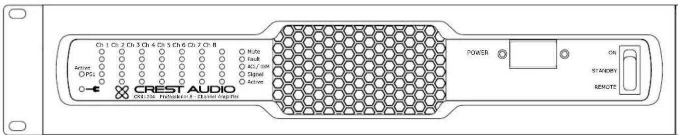
This section identifies and labels all the switches, indicators, connectors and functional components with which a CKd owner should become familiarized. Getting to know the items in this section and their locations on the CKd will make the manual much clearer. Keep in mind that this only as an overview of the amplifier's layout, and does not contain all the information necessary to effectively operate the CKd Amplifier. For more detailed information on many of the items listed here, see Amplifier Operation.
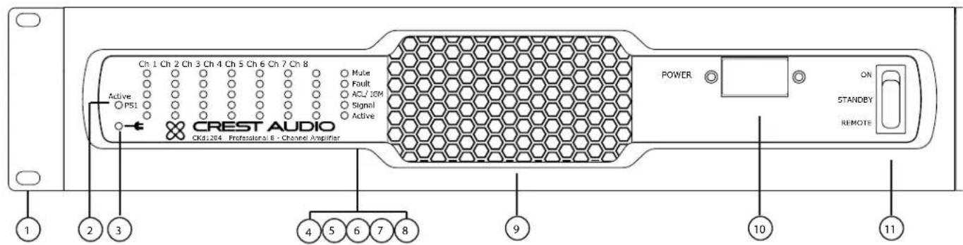
1. Rack Mounting Ears
Two mounting holes are provided on each front mounting ear.
2. PS LED (Power Supply)
The PS LED, when fully lit, indicates that power supply is active. When the PS LED is blinking fast, it indicates an Amplifier Level Fault. Amplifier Level Faults include: AC Voltage Faults, Low Voltage DC Rail Faults, Fan Faults. When the PS LED is blinking slowly, it indicates a Power Supply Level Fault. Power Supply Level Faults include; High Voltage Rails Fault, Bias Voltage Rail Fault, Breaker Tripped, and DC Fault. For more details regarding LED Fault identification, please see appendix.
3. LED (AC Voltage present)
The AC Voltage Present LED, when fully lit, indicates that the unit has incoming AC voltage.
4. Channel Active LED
The channel 'Active' LED notes the channel's Active status. For channels to be Active, the unit must be set "On" or "Remote" by the front panel switch or through software control and the corresponding power supply must be Active. Individual channels can be set Active
The three-position Power Switch never disconnects the AC mains. Hazardous energy may be present in the enclosure when the power switch is in any position.

Make certain that there is enough space around the front and rear of the amplifier to allow the heated air to escape.
Suggestion: In racks with closed backs allow at least one standard-rack-space opening for every four amps.
by turning the channel attenuators >-∞ , or through software control. Please note that when a channel is deactivated by the rear panel attenuator, it can not be set active through software control.
5. Channel Signal LEDs
Indicates presence of a signal.
6. Channel ACL/IGM LED
The ACL (Automatic Clip Limiter)/IGM (Instantaneous Gain Modulation LED indicates the channel protection limiter is active because it either exceeded its maximum voltage (ACL) level or current (IGM) level or temperature. The temperature limit is distinctly noted when the channel LED is continuously and dimly lit. See Page 14.
7. Fault LEDs
Each Channel has a fault LED which indicates channel Faults. When lit, the channel will not pass audio.
8. Mute LEDs
Each channel has a Mute LED. If a channel is muted, this LED will light. The Mute LED's also denote Faults when a Device or Power Supply Fault occurs. Please see appendix for more information.
9. Fan Filter
A high-efficiency DC fan draws cool air into the amplifier though the safety grill and removable dust filter. Do not block this intake! The variable speed fan operates when the unit is "Active". Fan filters are easy to remove and should be cleaned regularly to ensure optimum performance.
10. Power Supply Breaker
Magnetic circuit breaker for power supply.
11. Three-position Power Switch
With this switch in the "up" position the amplifier is "Active" (On). The middle position is "Standby" (Off) and the lower position is marked Remote. When switched to Remote, the amplifier must be activated by the sequential turn on/turn off (STO) circuit or NexSys or NWare software.
Because of the complexity of the design and the risk of electrical shock, all repairs must be attempted only by qualified technical personnel. If the unit needs to be shipped back to the factory, it must be sent in its original carton. If improperly packed, your amplifier may be damaged.


1. AC Power Cord
See Appendix for AC load requirements and circuit breaker ratings.
2. STO Connectors
These connectors can be wired to a contact closure for remote turn-on/off and to other CKd/Ci/Cki/CK amplifiers for sequential turn-on (STO). See Page 12.
3. Rear Panel Status LED's
Same as front panel status LED indicators.
4. "100V/70V/Low Z" Channel Mode/Gain Switch
This switch sets the amplifier's gain structure as "70V" constant voltage (1.414V Sensitivity) or "100V" constant voltage (2.0V Sensitivity.) or "Low Z" constant gain (x40 settings). This switch also sets thresholds for IGM and ACL accordingly. In '100V' or '70V' modes, the 70Hz, 3 pole, high pass filter (by default) is automatically engaged. In 'LowZ' mode, the HPF is disengaged (by default). See Page 14.
5. Channel Attenuators
Each channel has an attenuator knob to adjust the channel's output from -∞ to 0 dB. When set to -∞ , the channel is deactivated and the 'Active' LED will turn off. To improve power and thermal performance, it is recommended to deactivate unused channels.
6. Amplifier Output Connectors
Barrier strips provide speaker level output connections. High voltages are present at these terminals. Protective covers are provided. Bare wire or spade lugs may be used to make barrier strip connections. See Output Connections section for more information.
7. Control Voltage Inputs
Each channel has a Control Voltage Input. Using a 1K Ohm potentiometer across the +/- terminals, these inputs (by default) control the volume of the corresponding amplifier channel. These inputs can be further programmed using NexSys or NWare Software.
Rear panel LED's assist in troubleshooting from the back of the rack.

8. Analog Audio Inputs
The CKd uses on 3-pin mini Euroblock connector per channel for balanced line-level audio input. These inputs can also be setup to accept an unbalanced signal.
9. Module Bay
The rear panel of a CKd Power Processing amplifier provides a module bay configured to accept interchangeable plug-in modules. Your amplifier may have been factory configured with one of the optional modules. In this case, additional information on the relevant modules will be enclosed in the amplifier box, or in a separate binder. If all required information is not included, please call Crest Audio's Customer Service department or your local Crest Audio representative
10. Relay Fault Outputs
Each channel has a Fault output contact closure. When a channel fault occurs, this contact closure will engage. These contact closures can be further programmed using NexSys or NWare Software.
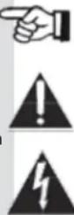
Side Panels
natural_image
Two rows of circular patterns: one with horizontal lines and one with a grid of circles, no text or symbols present.Exhaust Ports
The front panel fan pushes air into the unit and heated air exits through the exhaust ports, located on the sides of the amplifier chassis. Do not block these ports when rack-mounting the amplifier.
Amplifier Operation
Input Sources
CKd Power Processing amplifiers are designed to accept a balanced input signal. For use with an unbalanced source, please see the diagram below.

Output Connections
Speakers are connected using the Output Barrier Strip connectors. Spade lugs, ring tongues or bare wire may be connected to the output barrier strip elements. Spade Lug measurements for Output barrier strip are as follows: 0.44" (11mm) screw spacing, 0.35" (9mm) lug space. For output spade lugs, please review the suggested parts below:
nylon insulated, metal insulation grip sleeve, 12 – 10 AWG wire range, #10 stud size.
3M Part Numbers:
LFV10-6, LFV10-8, LFV10-10 - Locking Fork, Vinyl Insulated, Butted Seam, 12 – 10 AWG wire range
Consult the wire gauge charts in Appendix D for speaker wiring recommendations. Make sure the amplifier is turned off before you change any output connections or jumpers. Also ensure that the impedance of the load being connected is not less than the amplifier's recommended minimum load.
Output Configuration
In standard channel mode, all channels operate independently. Individual input attenuators control the respective levels of each channel. By default, signal at Channel 1 input produces output at Channel 1 output, while signal at Channel 2 input produces output at Channel 2 output and Channel 3 input produces output at Channel 3 output, etc.. Please be sure to properly set the channel Mode/Gain Switches (100V, 70V, LowZ) as this sets both gain and impedance dependant protection thresholds. See table below for minimum nominal load impedance for Mode/Gain Switches (100V, 70V, LowZ) settings of CKd Series amplifiers.
Mode 604/608 Minimum Impedance 12 04 Minimum Impedance
| 100VMode: 16 Ohms | 8 Ohms |
| 70V Mode: 8 Ohms | 4 Ohms |
| LowZ Mode: 4 Ohms | 4 Ohms |
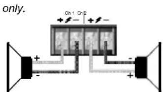
Connect loudspeakers to the barrier strip output connectors for all channels 1 thru 8. Connections are shown in the diagram at right.
Further audio routing can be configured using Nx modules via software.

Never connect a + or - terminal directly to another + or - terminal.

Mode/Gain Selection Switch (100V, 70V, LowZ)
The three-position gain select switch found on the rear panel of the CKd is used to set the overall gain and protection thresholds (ACL & IGM) of the amplifier channels. The '100V' position set's the channel gain to x50 with a 2.0V sensitivity. The '70V' position set's the channel gain to x50 with a 1.414V sensitivity. The 'LowZ' position set's the channel gain to x40 with a 1.4V sensitivity for 8 Ohms and 1.0V sensitivity for 4 Ohms loads. The protection limiter thresholds are adjusted accordingly.
In '100V and '70V' modes, a 70 Hertz, third order, high pass filter is automatically engaged. In 'LowZ' mode, the HPF is disengaged. Further control of the HPF can be done through software control. The HPF has two modes:
Auto Mode: (default) filter is automatically engaged / disengaged depending on the Mode/Gain switch.
Discrete Mode: HPF can be engaged / disengaged independent of the Mode/Gain switch.
Sequential Turn-On/Turn-Off (STO)
CKd Power Processing amplifiers come standard with Sequential Turn-On/Turn-Off (STO) circuitry. If the amplifier front power switch is set to "remote," a single SPDT toggle switch or two SPST momentary switches can be used to turn the amplifier on and off. Using the same switch(es), additional amplifiers can be turned on/off sequentially by daisy chaining the STO "Out" terminals of one amplifier to the STO "In" terminals of a subsequent amplifier. The standard turn-on delay time between amplifiers is approximately 100ms; turn-off delay time is 200ms. Note: when using NexSys or NWare control, hardwiring for manual switch closure between amplifiers should be used cautiously. If the switch closure output is wired up, it WILL cause the next amp to switch, regardless of which source (hardware switch or NexSys STO command) has initiated the command.
Standard Sequential Turn-On/Turn-Off Wiring
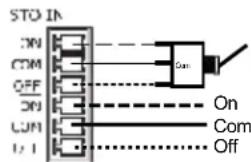
For non-NexSys remote turn-on, a single SPDT toggle switch or two SPST momentary switches can be used. In either case, the switch(es) are wired to the "STO In" connector on the amplifier's rear panel and the amplifier's front panel power switch must be set to "Remote." With an SPDT toggle, the center tap of the switch must be wired to the "Com" pin on the connector, one of the end taps must be wired to the "On" pin, and the other end tap must be wired to the "Off" pin. When the switch shorts the "On" and "Com" pins, the amplifier will turn-on. Likewise, throwing the switch and shorting the "Off" and "Com" pins turns the CKd off. See the diagram below:
STC OUT
SPDT Switch
To STO In of next amp
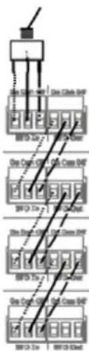
With two SPST momentary switches, one switch must be wired across the "On" and "Com" pins, and the other switch must be wired across "Off" and "Com" pins. When the first switch is depressed, it shorts the "On" and "Com" pins, turning the amplifier on. Depressing the other switch will short the "Off" and "Com" pins, turning the CKd off. See the diagram below:

Any number of CKd, Ci, CKi or CKS/V/X amplifiers can be daisy-chained together for sequential turn-on. Wiring two amplifiers for STO is as simple as connecting the "On," "Com" and "Off" pins of the "STO Out" connector on the first amplifier to the corresponding pins on the "STO In" connector on the second amplifier. Repeating this wiring scheme with subsequent amplifiers allows entire systems of CKd's to be wired for STO.
STO connections are optically isolated so connecting amplifiers from different AC feeds will not create grounding (hum) issues.

flowchart
graph TD
    A["Power Source"] --> B["Switch"]
    B --> C["Ground"]
    D["Power Source"] --> E["Switch"]
    E --> F["Ground"]
    G["Power Source"] --> H["Switch"]
    H --> I["Ground"]
    J["Power Source"] --> K["Switch"]
    K --> L["Ground"]
    M["Power Source"] --> N["Switch"]
    N --> O["Ground"]
Amp 1
Amp 2
Amp 3
Amp 4
TourClass® Protection Features
Every model in the CKd Power Processing line incorporates Crest Audio's TourClass protection features. Derived from Crest's extensive experience with the world's largest sound rental companies, the TourClass group of features sets new standards in load and amplifier protection.
Automatic Clip Limiting (ACL)
Automatic Clip Limiting (ACL) circuitry protects both loudspeakers and audio fidelity against damaging square-wave clipping. When the amplifier reaches its maximum output power (the point at which the amplifier would begin to clip), the ACL circuitry automatically reduces the amplifier's gain to keep the signal from being driven into hard clipping. Situations that may activate ACL include: uncontrolled feedback, oscillations, or an improper equipment setting or malfunctions upstream from the amplifier. Normal program transients will not trigger ACL, only steady or excessive clipping. ACL is virtually transparent in operation and full signal bandwidth is maintained.
Instantaneous Gain Modulation (IGM)
Instantaneous Gain Modulation (IGM) is an innovative impedance sensing circuit that allows the CKd amplifier to operate safely into any load. When the amplifier sees a load that overstresses the output stage, the IGM circuit reduces the channel gain to a safe level. Like ACL, the IGM circuit is sonically transparent in normal use.
Thermal Protection
If the temperature of the amplifier's output devices becomes abnormally high, the CKd channel will protect itself by shutting down the amplifier's output stage. The channel's 'Active' LED will turn off and the channel 'Fault' LED will light if this occurs. Once adequately cooled, the amplifier channel will resume operation automatically.
A thermal limiter option is available to further protect channels from shutting down due to thermal faults. The thermal limiter will activated when a channel approaches its thermal limit. This is indicated by a dimly lit ACL/IGM LED. When the thermal limiter is active, the channel will lower its IGM threshold until the temperature stabilizes.
Short Circuit
If an output is shorted, the IGM and thermal circuits will automatically protect the amplifier. The IGM circuit senses the short circuit as an extremely stressful load condition and attenuates the signal, protecting the channel's output transistors from over-current stress.
DC Voltage Protection
If an amplifier channel detects DC voltage at its output terminals, amplifier channels will shutdown to prevent loudspeaker damage. When a DC voltage is detected on channels 1 through 4, Power Supply 1 will shut down, deactivating channels 1 through 4. When a DC voltage is detected on channels 5 through 8, Power Supply 2 will shut down, deactivating channels 5 through 8.
AutoRamp Protection
AutoRamp gradually increases the amplifier gain from -∞ to the attenuator setting every time the amplifier is turned on or is reactivated after a protect condition. This exclusive Crest feature avoids unnecessary stress on the loudspeakers by
Because of the complexity of the design and the risk of electrical shock, all repairs must be attempted only by qualified technical personnel. If the unit needs to be shipped back to the factory, it must be sent in its original carton. If improperly packed, your amplifier may be damaged.

preventing sudden bursts of audio from arriving at the amplifier's output after its output relays initially close.
NexSys Fault Monitoring
A CKd equipped with an NxDante8 or NxCobraNet8 module and connected to a NexSys network will report fault conditions to the PC controlling the network. If a networked amplifier enters ACL or IGM or experiences a thermal, DC voltage, or short circuit fault, the fault condition will be reported the PC interface. This allows easy monitoring of amplifier operating conditions across a large or widespread network from a single location.
Module Bay
CKd Power Processing amplifiers come standard with a blanking panel fixed over the module bay. When a NexSys module is installed in this bay, connection to a network is made via a standard RJ-45 connector and CAT-5 Ethernet cable.
Module Removal
Only module upgrades require modules to be removed from the amplifier. Contact Crest Audio Customer Service for full details on module removal. The 'General Module Setup' diagram indicates the general setup of the rear panel module/bay configuration.
Note: Removable modules contain static-sensitive devices; handle modules only at static-safe workstations!
Replacing or Installing a Network Module
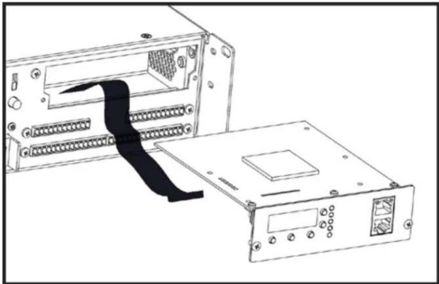
The amplifier must be switched off and unplugged from the AC mains supply before this operation is undertaken. Two Phillips head screws secure the module to the chassis. The module is connected electrically to the amplifier with a single multi-pin ribbon cable. Once unscrewed from the chassis, unplugging the module from this ribbon cable frees the module for removal. To insert a module, simply reverse this procedure.
Note: Standard CKd Power Processing amplifiers come with a blank panel installed in the Network bay. The amplifier must not be operated without a Network module or blank panel in place.
Service or Technical Inquiries
For Crest Audio service, parts or technical assistance, please call our toll free customer service number: 866.812.7378.
NexSys Module Basics and Installation
Although the CKd Power Processing amplifiers are venerable audio workhorses in their own right, the true breadth of their capabilities is only reached once they are tied into a NexSys amplifier network. In order for a CKd to capitalize on this network potential, it must be equipped with one or more of a series of NexSys modules. These modules reside in the CKd's module bay (see Amplifier Layout for the exact location of the module bay) and provide numerous control, monitoring, and signal processing features to the NexSys system. This section will cover installation NexSys modules as well as important information concerning computer control of a NexSys system.
Overview
The extended capabilities of CKd amplifiers are reached when connected to a NexSys amplifier network via a NexSys module. These modules reside in the CKd's module bay and provide control, monitoring, and signal processing features. This section covers the installation of NexSys modules as well as information concerning computer control of a NexSys system.
Module Installation
There are two modules through which a CKd amplifier can be connected to a NexSys network – the NxDante8 Module and the NxCobranet8 Module. Although they have different feature sets, they both serve the networking function. Because of this, they are collectively referred to as “NexSys network modules.” The installation procedure for both is the same.
-
Remove the blank panel covering the CKd's module bay by removing the screws on either side of the panel. Save these screws, as they will be needed for fastening the network module.
-
Inside the exposed module bay you should see the ribbon cable connector on the amplifier's circuit board. Note of the way the connector is keyed, and position the ribbon cable to match. Insert the cable into the connector, with the opposite end hanging out of the module bay.
-
Position the network module right side up. Connect the exposed end of the ribbon cable to the connector on the module, again taking note of the keying of the connectors.
-
Slide the module into the bay, and fasten it to the CKd's chassis with the screws removed in Step #1.
natural_image
Line drawing of an electronic device showing a rack-mounted unit connected to a power strip (no text or symbols)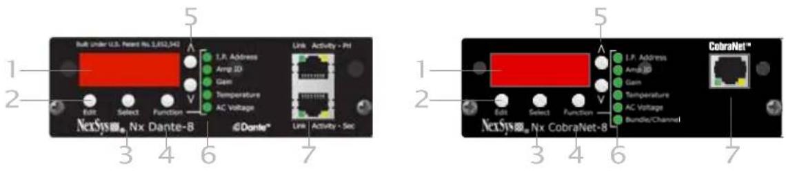
NexSys Modules
Module Features
These following pages describe the buttons, indicators, connectors and functional components that are relevant to the two NexSys modules. These features exist on both the NxDante8 and NxCobranet8 Modules. Features specific to the NxCobranet8 Module are discussed later in this section.
1 4-character Display
The LED display shows the value of the current parameter for the function chosen. The selected Function is indicated by the corresponding LED.
2 Edit Button
Enables and disables editing of a function parameter. When pressed, the value in the display will flash, indicating that edit mode has been entered. The value can now be adjusted using the increment and decrement buttons. Pressing Edit again will register the value and stop the flashing of the display.
3 Select Button
When a function parameter exists for each independent channel (e.g. Gain, Temperature), this button changes the parameter values for each individual channel. This button is also used to select parameters within a given function.
4 Function Button
This button scrolls through the functions that can be controlled from the module panel including: I.P.Address, Amp ID, Gain, Temperature, AC Line Voltage. As each is selected, the corresponding LED wil light and the appropriate function parameter will appear in the display.
5 Increment/Decrement Buttons
When the module is in edit mode and the value in the display is flashing, the increment and decrement buttons will adjust the value.
6 Function LEDs
Each of the main functions has a corresponding LED. When a function is selected, this LED will light to identify the selection. Some secondary functions do not have an associated LED, so no LED will light when these functions are selected.
7 RJ-45 Network Connector
The RJ-45 connector allows connection of the Ci amplifier to an Ethernet network. The jack accommodates a standard male RJ-45 connector.
Data & Link LEDs
The Data LED will flash when data packets are being sent or received by the module.
Edited values are not saved while incrementing/decrementing. The value being edited is saved when exiting edit mode.
The Link LED will light when the module detects that it is connected to an Ethernet network.
Module Operation
The following pages contain information on how to operate the NxEthernet and NxCobraNet modules. The NexSys functions that can be controlled from the amplifier's rear panel will be explained. After working through this section, you should have an understanding of the network modules' operation through hardware. For more on software control of the modules' features, see the NexSys Manual.
The instructions in this section assume that a module has been mounted in the Ci amplifier and the user has a working knowledge of the module's control panel layout.
Making Network Connections
The Network modules are connected to the network via standard CAT-5 Ethernet cabling using and RJ-45 connector. When the cable has been physically connected to the module and to an active network device, the “Link” LED will illuminate.
Setting IP Addresses
Press the Function button until the LED next to I.P.Address illuminates. Once the function has been chosen, depressing the Select button will scroll through the four octets of the I.P.Address. The position of the decimal point in the numeric display designates which octet has been selected. If the decimal point is to the left of all three digits, then the first octet is being displayed. If the decimal is between the first and second digit, the second octet is being displayed and so on. Once the appropriate octet has been selected, press the Edit button. The octet value will begin flashing. Press the increment and decrement buttons to change the octet value. There are 256 possible values for each octet, ranging from 0 to 255. Once the correct value has been reached, press the Edit button again to register the value and exit edit mode. If another octet value must be changed, select it using the Select button and repeat the editing procedure. Setting the I.P.Address to 000.000.000.000 will enable DHCP for this amplifier. Under this setting a connected DHCP server will dynamically assign an I.P.Address to the amplifier.
Setting Amplifier ID
Use the Function button to choose Amp ID. Each Amp ID is composed of two, two-digit hexadecimal values (see Appendix C for more information on Hex Numbering). The upper two digits (the High Value) and the lower two digits (the Low Value) can be independently adjusted. For this function, the Select button toggles between these two values.
Select a value for adjustment, and press Edit. The selected portion of the ID will flash, and the increment and decrement keys can now be used to adjust the value. An amplifier's I.P.Address can be used to designate an amp in a network, however Amp ID is more useful for designation, particularly when DHCP is being used.
Network Examples
NexSys Modules 7
Amplifier IDs can remain fixed even if I.P.Address change, making the amplifier's settings and operating conditions easier to track. Additionally, creative use of the High and Low Values in the Amp ID can provide even more information about an amplifier. Since the two values can be adjusted independently, the High Value could
Not all function parameters can be adjusted (e.g. AC Line Voltage, Temperature, etc.) as they are output values only.
Firmware revision 0.2.61 and later allows two speed value editing. For example, when setting the IP Address on the module, first select the IP Address octet to be edited. Then press the "Edit" button. Next, press the up/down arrow to increment/decrement the value at a slow speed. Or, press the up or down arrow in conjunction with the "Function" button to increment/decrement the value at a faster speed.
Note: For instructions on I.P.Addresses, designing and setting up a complete network, please see Appendix C:
be used to designate a group of amplifiers, while the Low Value would identify specific amplifiers in that group.
Adjusting Gain
Use the Function button to choose Gain. In this mode, the Select button chooses between Channel 1 thru 8. With the proper channel selected, press the Edit button. The increment and decrement buttons will now adjust the channel's gain. If the channel has been muted by NexSys, the first press of either the increment or decrement will bring the channel out of mute and return its previous value. Subsequent presses will adjust the gain value. Once the gain has been adjusted, pressing the "Edit" button again will lock in the value and the display will stop flashing. Gain values are listed in dB, from 0 (unity) to -80. The setting of the amplifier's attenuators will also affect the overall gain. The attenuators are positioned after the NexSys gain control in the amp's gain structure resulting in an additive attenuation value. For example, if an attenuator is set to -6dB, and the NexSys gain for that channel is set to -10dB, the amplifier's overall gain will be 16dB below the amplifier's maximum output.
Condition Monitoring
These functions do not make use of the Edit and increment/decrement buttons. They simply provide information concerning the amplifier's operating condition.
Temperature
Use the Function button to choose Temperature. The internal ambient temperature of the amplifier will be displayed with a designation of "F" for degrees Fahrenheit or "C" for degrees Celsius. To change the units that the temperature is displayed in, press the Select button.
AC Line Voltage
Use the Function button to choose AC Voltage. The AC line voltage will be displayed. The AC Voltage is only reported on 120V CKd models.
The Amp ID's
The Amp ID's given to each amplifier in a NexSys system are composed of two independently adjustable two-digit hexadecimal values. It is not necessary to fully understand hexadecimal numbering in order to set an Amp ID, but it is helpful to know. Also, when the numeric display reads "AE," the operator will realize this is a completely normal number when working in hex, and there is no cause for alarm!
Hexadecimal or “hex” numbering is a system of counting widely used in digital technology and in the design of digital systems. This is largely because of its close relationship to binary numbering, which is the counting scheme that makes up the fundamentals of all digital technology. Hexadecimal is a Base-16 numbering system, as opposed to binary, which is Base-2, or our comfortable, everyday decimal numbering system, which is Base-10.
The “base” of a numbering system is simply the number of digits in the system. For example, the garden-variety decimal system has ten digits (“0,” “1,” “2,” “3,” “4,” “5,” “6,” “7,” “8,” and “9”) and therefore we say it is a Base-10 system. Binary, as the name implies, has only two digits – the lowly “1” and the humble “0.” However, these two digits can still be used to represent infinitely large numbers just as effectively as the decimal system. In fact, while most humans think in terms of the decimal system computers and digital devices “think” in terms of the binary system.
Hex uses sixteen digits – all of the numerals used in the decimal system, plus the first six letters of the alphabet. Therefore, counting from zero in hex one has “0,” “1,” “2,” “3,” “4,” “5,” “6,” “7,” “8,” “9,” “A,” “B,” “C,” “D,” “E,” and “F.” Remember, the digits are just symbols representing a value – they could be numerals, letters, hieroglyphs, dots of different colors, anything. This is important to keep in mind, because many systems (including the three mentioned here) just so happen to use many of the same symbols, however in the different systems they may not always represent the same value. This is where confusion often arises, and it is an issue that will be address shortly.
Counting in the decimal system, once “9” is reached there are no more different symbols to use. The solution is to start combining digits in a logical fashion, by adding a new placeholder. The result is the number “10.” The value in this new place is worth ten times the placeholder to its right, and as we all know we can continue this pattern indefinitely. However, the reason each value is worth ten times the placeholder to its right is because decimal is a Base-10 numbering system. This is not a hard and fast rule, although it may seem to be because the Base-10 (decimal) system is used almost exclusively in day-to-day life. However, in Base-2 for example, each placeholder is worth two times the placeholder to its right, and in Base-16, sixteen times.
Here is the decimal example described:
1 0 = (1 ^ ten ) + (0 ^ one ) = ten
Likewise, other decimal values:
3 5 = (3 ^ 0) + (5 ^ ) = 3 0 + 5 = 3 5 5 2 8 = (5 ^ 1 0 0) + (2 ^ 1 0) + (8* 1) = 5 0 0 + 2 0 + 8
= 5 2 8 2 0 4 6 = (2 ^ 1 0 0 0) + (0 ^ 1 0 0) + (4 ^ 1 0) + (6 ^ 1) = 2 0 0 0 + 0 0 0 + 4 0 + 6 = 2 0 4 6
However, since this is really only converting decimal back into decimal, it is of limited usefulness. Retaining the above concepts and applying it to the other numbering systems makes things much more clear. Looking at Base-2, digits are in very short supply. Counting from zero, one has "0," "1," and then one must start again. Add a placeholder, and again the result is "10." However, now "10" represents two, not ten. The "1" in "10" binary has a value of two times the place to its right, and the place to its right has a one's value.
Analyzing this example with the approach used above:
1 0 = (1 ^ two ) + (0 ^ one ) = two
It becomes readily apparent that "10" does not always represent "ten," it is entirely dependent on the base of the numbering system being used. Other binary values:
| 0 0 0 | | b . = (1 ^ 3 2) + (0 ^ 1 6) + (0 ^ 8) + (0 ^ 4) + (1 ^ 2) + (1 ^ 1) = 3 2 + 0 + 0 + 0 + 2 + 1 = 3 5 0 0 0 0 0 0 0 0 b = (1 ^ 5 1 2) + (0 ^ 2 5 6) + (0 ^ 1 2 8) + (0 ^ 6 4) + (0 ^ 3 2) + (1 ^ 1 6) + (0 ^ 8) + (0 ^ 4) + (0 ^ 2) + (0 ^ 1) = 5 2 + 0 + 0 + 0 + 0 + 1 6 + 0 + 0 + 0 + 0 = 5 2 8 0 b = (1 ^ 1 0 2 4) + (1 ^ 5 1 2) + (1 ^ 2 5 6) + (1 ^ 1 2 8) + (1 ^ 6 4) + (1 ^ 3 2) + (1 ^ 1 6) + (1 ^ 8) + (1 ^ 4) + (1 ^ 2) + (0* 1) = 1 0 2 4 + 5 1 2 + 2 5 6 + 1 2 8 + 6 4 + 3 2 + 1 6 + 8 + 4 + 2 + 0 = 2 0 4 6
Of course, a similar approach can be applied to hex. However, this time there are more digits than in decimal. Now, counting to “9” is the same as in decimal, but it is possible to continue on with “A,” “B,” “C,” “D,” “E,” and “F.” It is only once “F” is exceeded that a new placeholder is required, and it will of course have a value sixteen times that of the placeholder to its right. If we use our example of “10” again, the “I” is worth sixteen, so the number represented in this case is sixteen.
Approaching "10" with the above method in hex:
1 0 = (1 ^ sixteen ) + (0 ^ one ) = sixteen
Yet another proof that "10" does not always mean "ten." Here are other hex examples:
2 3 h = (2 ^ 6) + (3 ^ ) = 3 2 + 3 = 3 5 2 1 0 h = (2 ^ 2 5 6) + (1 ^ 1 6) + (0 ^ 1) = 5 1 2 + 1 6 + 0 = 5 2 8 7 FEh = (7 ^ 2 5 6) + (1 5 ^ 1 6) + (1 4 ^ 1) = 1 7 9 2 + 2 4 0 + 1 4 = 2 0 4 6
Wire Gauge
| Stranded Cable Length | Wire Gauge | 8 Ω load | Power Loss4 Ω load | 2 Ω load |
| 1.5 | 0.58 | 1.16 | 2.3 | |
| 2.5 | 0.35 | 0.70 | 1.39 | |
| 4.0 | 0.22 | 0.44 | 0.87 |
| 5 meters | 0.5 mm 2 | 4.3% | 8.2% | 15.5% |
| 0.75 | 2.9 | 5.6 | 10.8 | |
| 1.5 | 1.45 | 2.9 | 5.6 | |
| 2.5 | 0.87 | 1.74 | 3.4 | |
| 4 | 0.55 | 1.09 | 2.2 | |
| 6 | 0.37 | 0.73 | 1.45 |
| Stranded Cable Length | Wire Gauge | Power Loss | ||
| 8Ω load | 4Ω load | 2Ω load | ||
| 18AWG | 0.81% | 1.61% | 3.2% | |
| 16 | 0.51 | 1.02 | 2.0 | |
| 14 | 0.32 | 0.64 | 1.28 | |
| 12 | 0.20 | 0.40 | 0.80 | |
| 10 | 0.128 | 0.25 | 0.51 | |
| 10 feet | 18AWG | 1.61% | 3.2% | 6.2% |
| 16 | 1.02 | 2.0 | 4.0 | |
| 14 | 0.64 | 1.28 | 2.5 | |
| 12 | 0.40 | 0.80 | 1.60 | |
| 10 | 0.25 | 0.51 | 1.01 |
| s 10 th | 0.5mm | 8.24% | 5.5% | 28% |
| 0.75 | 5.6 | 10.8 | 19.9 | |
| 1.5 | 2.9 | 5.6 | 10.8 | |
| 2.5 | 1.74 | 2.9 | 6.7 | |
| 4 | 1.09 | 1.74 | 4.3 | |
| 6 | 0.73 | 1.09 | 2.9 |
| 40feet | 6.2% | 11.9% | 22% | |
| 18AWG | 4.0 | 7.7 | 14.6 | |
| 16 | ||||
| 14 | 2.5 | 5.0 | 9.6 | |
| 12 | 1.60 | 3.2 | 6.2 | |
| 10 | 1.01 | 2.0 | 4.0 | |
| 8 | 0.60 | 1.20 | 2.4 |
| 30meters 0.75mm2 | 15.5% | 0.73% | 45% |
| 8.2 | 15.5 | 28 | |
| 2.5 | 5.1 | 9.8 | 18.2 |
| 4 | 3.2 | 6.3 | 12.0 |
| 6 | 2.2 | 4.3 | 8.2 |
| 10 | 1.31 | 2.6 | 5.1 |
| 80 feet | 11.9% | 22% | 37% | |
| 16AWG | 7.7 | 14.6 | 26 | |
| 14 | 5.0 | 9.6 | 17.8 | |
| 12 | 3.2 | 6.2 | 11.8 | |
| 10 | 2.0 | 4.0 | 7.7 | |
| 8 | 1.20 | 2.4 | 4.7 |
Identifying CKd Amplifier Fault Codes and Amplifier Firmware Revision
This document explains how to identify the fault codes and versions displayed on the front and rear panel LED's during the initialization process of CKd amplifiers.
When the amplifier is turned on via the front panel switch or remotely, the amplifier begins an initialization process. This process has three phases;
- All LED's On
- Faults and Version on LED's
- Channel initialization
The “All LED’s On” phase occurs first when power is turned “On”. All the LED’s will light for about 1 second. Then the Signal LED’s will display the revision of the amplifier firmware (which is separate from the NexSys module firmware) and the “Mute” LED’s will display any faults. If there are no faults, all of the “Mute” LED’s will be off.
The “Faults and Version” phase will be displayed for a minimum of 1 second or as long as faults are active. The lit Signal LED’s represent the binary version number. Once all the faults are cleared, the amplifier will continue to the “Channel Initialization” phase.
Next, all the LED's will shut off and each channel will simultaneously initialize. During "Channel Initialization", all channels will simultaneously activate, lighting the Active LED. The channel is now active. If a channel does not activate, make sure the attenuation knob is turned up and that the channel is not deactivated in software.
There are three levels of 'Faults'; Device Faults, Power Supply Faults and Channel Faults.
- Device Faults are ones that affect the entire device and prevent all channels from passing audio.
• Power Supply Faults only prevent its associated channels from passing audio. - Channel Faults only prevent individual channels from passing audio.
Device Faults can be flagged even when the amplifier, power supplies or channels are active or not active. During a Device Fault, the PS LED will blink at a fast rate. While the PS LED is blinking, the Mute LED's will indicate which fault triggered as noted below:
• CH1 Mute LED: +15 Volt Rail fault
• CH2 Mute LED: -15 Volt Rail fault
• CH3 Mute LED: -5 Volt Rail Fault
• CH4 Mute LED: AC Voltage Line Fault
• CH5 Mute LED: Logic Rail Monitor Fault
• CH6 Mute LED: Fan Fault
• CH7 Mute LED: Audio CoDec Voltage Fault
• CH8 Mute LED: ADC Rail Monitor Fault
Please note: When the PS LED is blinking at a fast rate, a Device Fault occurred.
Power Supply Faults are flagged when a power supply is activated. During a Power Supply Fault, the PS LED will blink at a slower rate. While the PS LED is blinking, the Mute LED's will indicate which fault triggered as noted below:
• CH1 Mute LED: PS Voltage Fault
• CH2 Mute LED: PS Bias Voltage Fault
• CH3 Mute LED: PS Breaker Tripped
• CH4 Mute LED: PS DC Fault
• CH5 Mute LED: PS Voltage Fault (repeated)
• CH6 Mute LED: PS Bias Voltage Fault (repeated)
• CH7 Mute LED: PS Breaker Tripped (repeated)
• CH8 Mute LED: PS DC Fault (repeated)
Channel Faults are flagged when a channel is Active. During a Channel Fault, the corresponding channels Fault LED will light, the channel will shutdown and not pass audio. The channel will try to recover from the fault and activate automatically. The following items are recognized as Channel Faults:
• Over Current Fault
• Full limiter attenuation
- Thermal
- Initialization
A distributed or constant voltage system, as shown in the figure below, uses loudspeaker step-down transformers for each speaker. The transformers are designed to deliver a specific power level into a specific load impedance when a specific voltage (the example here uses 70.7 volts) appears at the primary. A speaker transformer usually has taps on its primary, secondary, or both, so it can be used for several different power levels or speaker impedances. Each speaker step-down transformer converts the low impedance of its loudspeaker to a relatively high impedance as seen by the distributed line. Consequently, loads can be added or subtracted to the distributed line with very little effect on the actual line voltage, hence the term "constant voltage." The actual line load Z that the amplifier "sees" is determined by the formula
Z = V 2 / P
where P is the sum of the loudspeaker power taps, compensated for transformer insertion loss;
(P = X [xfrmr#1] * P [speaker#1] + X [xfrmr#2] * P [speaker#2] + ...), and V is the distributed line voltage. So, for a 70.7 volt line,
Z = (7 0. 7) 2 / P
Z = 5 0 0 0 / P
For example, if the total power demanded by the speakers is 200 watts, then:
V 2 / P = 2 5
The compensation factor for transformer insertion loss is:
x = power drawn from distributed line
power delivered to speaker = 10 Insertion loss (in dB)/ 10
Therefore, a speaker transformer with an insertion loss of 1 dB, tapped at 4 watts, will actually demand 1.26 times 4 watts, or about 5 watts. Ci Series amplifiers are specifically designed for use with distributed or constant voltage systems. Each Ci Series model can drive up to eight distributed lines (one per channel) of the type for which they are configured, any number of tapped loudspeakers can be placed on a line as long as the total demanded power including insertion losses does not exceed the rated power of the model chosen. If the impedance of a distributed line overly stresses the amplifier output stage, the amplifier's IGM protection circuits engage, reducing gain in order to protect the amplifier.

| MODEL | CKd 608 | CKd 1204 | CKd 604 |
| Rated Power @ 4 Ohms 1KHz single channel driven | 660 watts per channel at <0.05% | 1,400 watts per channel at <0.1% | 700 watts per channel at <0.05% |
| Rated Power @ 8 Ohms 1KHz single channel driven | 660 watts per channel at <0.05% | 1,300 watts per channel at <0.15% | 680 watts per channel at <0.05% |
| Rated Power @ 70.7 volts 1KHz single channel driven | 660 watts per channel at <0.05% | 1,250 watts per channel at <0.05% | 670 watts per channel at <0.05% |
| Rated Power @ 100 volts 1KHz single channel driven | 660 watts per channel at <0.025% | 1,250 watts per channel at <0.05% | 670 watts per channel at <0.05% |
| Rated Power @ 4 Ohms all channels driven | 625 watts per channel at <0.05% | 1,250 watts per channel at <0.05% | 670 watts per channel at 1KHz |
| Rated Power @ 8 Ohms all channels driven | 625 watts per channel at 1KHz* | 1,250 watts per channel at 1KHz* | 670 watts per channel at 1KHz |
| Rated Power @ 70.7 volt all channels driven | 625 watts per channel at 1KHz* | 1,250 watts per channel at <0.05% | 625 watts per channel at 1KHz |
| Rated Power @ 100 volt all channels driven | 625 watts per channel at 1KHz* | 1,250 watts per channel at 1KHz* | 625 watts per channel at 1KHz |
| Minimum Load Impedance | 4 Ohms | 4 Ohms | 4 Ohms |
| Frequency Response @ 1W (8 Ohm load) | 10Hz - 20KHz, 0 dB to +0.5dB | 10Hz - 20KHz, 0 dB to +0.5dB | 10Hz - 20KHz, 0 dB to +0.5dB |
| Damping Factor (8 Ohms) | >150:1 @ 20Hz - 1KHz | >200:1 @ 20Hz - 1KHz | >200:1 @ 20Hz - 1KHz |
| Input CMMR | <-75 dB @ 1KHz | <-75 dB @ 1KHz | <-75 dB @ 1KHz |
| Voltage Gain Low Z | X 40 (32 dB) | X 40 (32 dB) | X 40 (32 dB) |
| Voltage Gain 70V / 100V | X 50 (34 dB) | X 50 (34 dB) | X 50 (34 dB) |
| High Pass Filter | 70Hz, 3rd order HPF | 70Hz, 3rd order HPF | 70Hz, 3rd order HPF |
| Input Sensitivity Low Z | 1.25V at 1KHz 4 Ohm rated power1.77V at 1KHz 8 Ohm rated power | 1.77V at 1KHz 4 Ohm rated power2.50 at 1KHz 8 Ohm rated power | 1.25V at 1KHz 4 Ohm rated power1.77V at 1KHz 8 Ohm rated power |
| Input Sensitivity High Z: 70V / 100V | 1.4V at 1KHz 70V 8 Ohm rated2.0V at 1KHz 100V 16 Ohm rated | 1.4V at 1KHz 70V 4 Ohm rated2.0V at 1KHz 100V 8 Ohm rated | 1.4V at 1KHz 70V 8 Ohm rated2.0V at 1KHz 100V 16 Ohm rated |
| Input Impedance | 20K Ohms balanced, 10K Ohms unbalanced | 20K Ohms balanced, 10K Ohms unbalanced | 20K Ohms balanced, 10K Ohms unbalanced |
| Noise and Hum | >-95dB, "A" weighted reference torated power at 8 Ohms | >-95dB, "A" weighted reference torated power at 8 Ohms | >-95dB, "A" weighted reference torated power at 8 Ohms |
| Current Consumption All Channels: Idle | 180 watts / 350VA,(162W 315VA @220V CN) | 126 watts / 260VA | 114 watts / 225VA |
| Current Consumption: at 1/8 power | At 4 Ohms/8 Ohms 70V/16 Ohms100V respectively:990W 1.540KVA /895W 1.408KVA/842W 1.342KVA | At 4 Ohms / 8 Ohms respectively:812W 1.35KVA /765W 1.26KVA | At 4 Ohms/8 Ohms 70V/16 Ohms100V respectively:530W 920VA /487W 852VA /431W774VA |
| Thermal Emission All Channels at Idle (Btu/hour) | 615 (553 @220V CN) | 430 | 389 |
| Thermal Emission All Channels at 1/8 power:(Btu/hour) | At 4 Ohms/8 Ohms 70V/16 Ohms100V respectively:977 / 935 / 911 | At 4 Ohms / 8 Ohms respectively:638 / 480 | At 4 Ohms/8 Ohms 70V/16 Ohms100V respectively:665 / 519 / 404 |
| Cooling | Temperature dependent variable speed 80mm DC fan | ||
| CONTROLS: Front Panel | On/Standby/Remote AC Switch, one21A circuit breaker for all 8 channels | On/Standby/Remote AC Switch, one21A circuit breaker for all 4 channels | On/Standby/Remote AC Switch, one13A circuit breaker for all 4 channels |
| CONTROLS: Rear Panel | 8 channel input signal attenuators, 8channel 100V/70V selection switches, two 3-position connectors for STO in and STO out, 8 Fault Relay Outputs (NO/NC), 8 Control Voltage inputs, NexSys module bay | 4 channel input signal attenuators, 4 channel 100V/70V selection switches,two 3-position connectors for STO In and STO out, 4 Fault Relay Outputs(NO/NC), 4 Control Voltage inputs, NexSys module bay | |
| INDICATOR LEDs: Front and Rear Panels | 8 Mute, 8 Fault, 8 ACL/IGM, 8 Signal,8 Active, 1 PS, 1 AC mains | 4 Mute, 4 Fault, 4 ACL/IGM, 4 Signal, 4 Active, 1 PS, 1 AC mains | |
| Protection per channel | Over temperature, DC, Subsonic, Incorrect Loads, Short-Circuit, Overcurrent, Thermal | ||
| Unit Protection | Over/Under AC Voltage, Fan operation, DC Voltage Fault | ||
| Connectors: for Input | Eight 3-position Euro-style detachable terminal blocks | Four 3-position Euro-style detachable terminal blocks | |
| Connectors: for Output | Four 4-position barrier strip terminal blocks with screws | Two 4-position barrier strip terminal blocks with screws | |
| Construction | 14-gauge aluminum reinforced chassis with 12-gauge steel rack ears | ||
| DIMENSIONS: Height | 3.48" (8.84cm), 2 EIA rack spaces | ||
| Width front | 19" (48.26cm) | ||
| Width rear | 17.25" (43.82cm) | ||
| Overall depth | 20.30" (51.56cm) | ||
| Mounting depth | 19.70" (50.04 cm) behind front rack ears | ||
| Net Weight (does not include power cord) | 23.4 lbs (10.60 kg) | 23.2 lbs (10.52 kg) | 21.2 lbs (9.62 kg) |
| Gross Weight | 29.4 lbs (13.3 kg) | 29.8 lbs (13.52 kg) | 27.8 lbs (12.6 kg) |
| Power Requirements | 120 VAC 60 Hz or 230 VAC 50Hz | ||
*repetitive 1KHz cycles 50ms onset of clip
04/19/2024

www.peaveycommercialaudio.com
Warranty registration and information for U.S. customers available online at
www.peavey.com/warranty
or use the QR tag below

Features and specifications subject to change without notice.
Crest Audio 5022 HWY 493 N. Meridian, MS 39305 (601) 483-5365 FAX (601) 486-1278

Logo referenced in Directive 2002/96/EC Annex IV (OJ(L)37/38,13.02.03 and defined in EN 50419: 2005
The bar is the symbol for marking of new waste and is applied only to equipment manufactured after 13 August 2005

- Caution
- Service Information
- Equipment should be serviced by qualified service personnel when:
- To obtain service,
- WARNING
- Introduction
- CKd Series Amplifier Features
- Installation
- Getting Started
- Unpacking
- Installation and Mounting
- Requirements and Considerations
- Circuit Size Requirements
- Cooling Requirements
- Thermal Emissions
- Rack Mounting Ears
- PS LED (Power Supply)
- LED (AC Voltage present)
- Channel Active LED
- Channel Signal LEDs
- Channel ACL/IGM LED
- Fault LEDs
- Mute LEDs
- Fan Filter
- Power Supply Breaker
- Three-position Power Switch
- AC Power Cord
- STO Connectors
- Rear Panel Status LED's
- "100V/70V/Low Z" Channel Mode/Gain Switch
- Channel Attenuators
- Amplifier Output Connectors
- Control Voltage Inputs
- Analog Audio Inputs
- Module Bay
- Relay Fault Outputs
- Exhaust Ports
- Amplifier Operation
- Input Sources
- Output Connections
- Output Configuration
- Mode/Gain Selection Switch (100V, 70V, LowZ)
- Sequential Turn-On/Turn-Off (STO)
- Standard Sequential Turn-On/Turn-Off Wiring
- SPDT Switch
- TourClass® Protection Features
- Automatic Clip Limiting (ACL)
- Instantaneous Gain Modulation (IGM)
- Thermal Protection
- Short Circuit
- DC Voltage Protection
- AutoRamp Protection
- NexSys Fault Monitoring
- Module Bay
- Module Removal
- Replacing or Installing a Network Module
- Service or Technical Inquiries
- NexSys Module Basics and Installation
- Overview
- Module Installation
- NexSys Modules
- Module Features
- 4-character Display
- Edit Button
- Select Button
- Function Button
- Increment/Decrement Buttons
- Function LEDs
- RJ-45 Network Connector
- Data & Link LEDs
- Module Operation
- Making Network Connections
- Setting IP Addresses
- Setting Amplifier ID
- Network Examples
- NexSys Modules 7
- Adjusting Gain
- Condition Monitoring
- Temperature
- AC Line Voltage
- The Amp ID's
- Here is the decimal example described:
- Identifying CKd Amplifier Fault Codes and Amplifier Firmware Revision
Brand : PEAVEY
Model : CKd 608
Category : Amplifier