
CA-A540B - Amplifier PEAVEY - Free user manual and instructions
Find the device manual for free CA-A540B PEAVEY in PDF.

| Product Type | Power Amplifier for Theaters and Cinemas |
| Brand | PEAVEY |
| Model | CA-A540B |
| Frequency Response | 20 Hz to 20 kHz, ±0.2 dB at rated power |
| Total Harmonic Distortion (THD) | Less than 0.07% at rated power |
| Slew Rate | 20 V/µs in stereo mode |
| Noise and Hum | 100 dB below rated power |
| SPS Protection | Patented protection system with LED indicators and switch (Enable/Defeat) |
| Cooling | Two-speed fans, rear intake and front exhaust |
| Operating Modes | Stereo and Bridge (STEREO/BRIDGE selector) |
| Minimum Output Impedance | 4 Ω per channel in stereo, 8 Ω in Bridge mode |
| Input Connectors | Electronically balanced terminal block (+, -, ground) |
| Output Connectors | Four-screw terminal block |
| Control Connector | Quick-Connect™ RJ11 for Peavey monitors |
| Power Supply | IEC connector, requires at least 7 A, mandatory grounding |
| Circuit Breaker | Resettable thermal protection on rear panel |
| Level Controls | Graduated in 3 dB increments |
| LED Indicators | Power LED and SPS enable LED (one per channel) |
| Mounting | Metal chassis for standard rack (dimensions not specified) |
| Maintenance and Cleaning | Use a dry cloth only |
| Safety | Do not expose to rain or moisture; do not open; refer service to qualified personnel |
| General Information | Amplifier designed for theater and cinema applications, with oversized transformers and advanced semiconductor output stage |
Frequently Asked Questions - CA-A540B PEAVEY
User questions about CA-A540B PEAVEY
0 question about this device. Answer the ones you know or ask your own.
Ask a new question about this device
Download the instructions for your Amplifier in PDF format for free! Find your manual CA-A540B - PEAVEY and take your electronic device back in hand. On this page are published all the documents necessary for the use of your device. CA-A540B by PEAVEY.
USER MANUAL CA-A540B PEAVEY
Intended to alert the user to the presence of uninsulated "dangerous voltage" within the product's enclosure that may be of sufficient magnitude to constitute a risk of electric shock to persons.

Intended to alert the user of the presence of important operating and maintenance (servicing) instructions in the literature accompanying the product.
CAUTION: Risk of electrical shock — DO NOT OPEN!
CAUTION: To reduce the risk of electric shock, do not remove cover. No user serviceable parts inside. Refer servicing to qualified service personnel.
WARNING: To prevent electrical shock or fire hazard, do not expose this appliance to rain or moisture. Before using this appliance, read the operating guide for further warnings.

- SPS™ compression with LED indicators and defeat switch
- Slew Rate: 20 V/microsecond, stereo mode
- Frequency Response (each channel): 20 Hz to 20 kHz, ± 0.2 dB , at rated power
- Total Harmonic Distortion: Less than 0.07% , at rated power
- Hum and Noise: 100 dB below rated power, unweighted
Congratulations! You are now the owner of a Peavey CinemAcoustics amplifier designed especially for the theater marketplace. The Peavey CinemAcoustics amplifiers, models CA-A540B and CA-A800B, are the result of the latest developments in technology, allowing Peavey to provide you with cost-effective amplifiers that do not sacrifice performance or reliability, while still continuing to meet the demanding needs of today's digital theater.
In the development of the CinemAcoustics CA-A540B and CA-A800B amplifiers, Peavey's engineers left no stone unturned. Right up front at the power source, CinemAcoustics' amplifiers utilize massive power transformers, which are based on a new approach to power transformer design, optimizing both cost and performance. On the power delivery side, these amplifiers utilize the latest in semiconductor power device technology and implement a unique, two-speed fan-cooled heat sink arrangement, insuring quality and ruggedness. The features and performance found in these amplifiers place them in a class of their own — the CinemAcoustics line!
Each amplifier is attractively packaged with rugged rack-mountable construction. The front panel of each amplifier contains a rocker mains power switch, an LED power indicator, and dual LED SPS activation indicators. The back panel of each amplifier has a resetable circuit breaker, an input level control, a Euro input connector, and an output barrier strip. Additionally, the back panel contains switches for stereo/bridge select and SPS defeat.
This operating guide is intended to serve both the CA-A540B and CA-A800B CinemAcoustics series power amplifiers. Although each has different power ratings, the overall packaging and features are similar.
FRONT PANEL CA-A800B
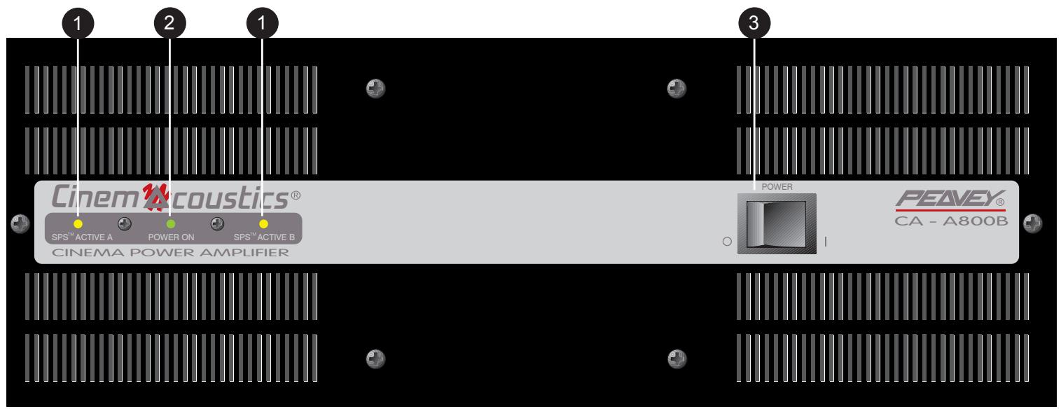
(1) SPS COMPRESSION ACTIVE LED
These indicators, one per channel, illuminate when SPS compression is taking place. This LED becomes a CLIP indicator when the rear panel SPS ENABLE/DEFEAT switch is in the DEFEAT position.
(2) POWER LED
This indicator illuminates when AC mains power is applied to the amplifier and both channels are operational. The power LED will go dark if AC mains power is disconnected, if either channel experiences a fault condition, or if the amplifier exceeds the safe operating temperature limits.
(3) MAINS POWER SWITCH
The mains power switch is a heavy-duty, rocker-type switch. Selecting the "O" position turns the power amplifier off. Selecting the "I" position turns the power amplifier on.
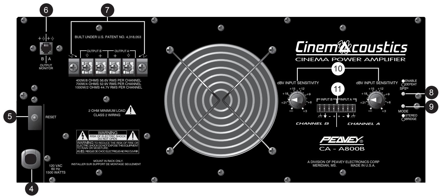
BACK PANEL CA-A800B
(4) MAINS POWER SOURCE
All CinemAcoustics Series power amplifiers are fitted with a single, heavy-duty, three-conductor line cord and a conventional, three-terminal AC plug with a ground pin for 120V products. For 100V and 220V products, the line cord is fitted with the appropriate power connector. The power plug should be connected to an independent circuit capable of supporting at least 15 amps for 100V and 120V service, and 7.5 amps for 220V service. This is particularly important for applications where the amplifiers will be continuously operated at, or near, their maximum power rating. The use of extension cords should be avoided, but when necessary, use a three-wire type with at least a 14 WG wire size.
Always allow a qualified electrician to install any new electrical service. The ground pin of the power plug is provided for your safety and should not be defeated. To prevent the risk of shock or fire hazard, always be sure that the amplifier is properly grounded.
NOTE: FOR UK ONLY
As the colors of the wires in the mains lead of this apparatus may not correspond with the colored markings identifying the terminals in your plug, proceed as follows: (1) The wire which is colored green and yellow must be connected to the terminal which is marked by the letter E, or by the earth symbol, or colored green or green and yellow. (2) The wire which is colored blue must be connected to the terminal which is marked with the letter N, or the color black. (3) The wire which is colored brown must be connected to the terminal which is marked with the letter L or the color red.
(5) CIRCUIT BREAKER
The power circuit breaker serves to protect the amplifier. The trip current value has been carefully chosen to allow continuous operation at the rated power while still offering adequate protection. Under normal conditions, the breaker will not trip unless there is a fault condition that draws excessive mains current. Please note, however, that abnormal conditions such as a short circuit applied to an output or continuous operation at overload or clipping will also cause the breaker to trip. If you suspect that the breaker has tripped because of abnormal conditions, be sure to remedy the cause of the fault before resetting the breaker. When tripped, the breaker button extends outward nearly 1/2" , and can be reset by pushing inward after a brief wait to allow the breaker to cool down. When not tripped, the breaker button extends outward about 1/4" . If the
breaker trips instantly each time you attempt to reset it, the unit should be taken to a qualified service center for repair.
(6) OUTPUT MONITOR
This standard Quick-Connect™ RJ11 modular connector provides Channel A and B signals to Peavey's booth monitor products such as the CA-M400. Refer to the diagram above the connector for proper polarity. (+ is equal to the channel's positive output.) The channels are indicated below the connector.
(7) BARRIER STRIP SPEAKER OUTPUTS
The SPEAKER OUTPUTS for each channel are provided by means of a heavy-duty, four screw barrier strip. The screw terminals marked “+” are the power amplifier outputs for each channel. The remaining screw terminals are ground (chassis). The minimum recommended speaker load impedance is 4 ohms per channel, or 8 ohms in BRIDGE mode. Operation into loads below the recommended load impedance can result in temporary amplifier shutdown due to internal fault sensing.
(8) SPS SWITCH
This switch is used to either ENABLE or DEFEAT the SPS safety compressor. Normally, the SPS switch should be in the ENABLE position to minimize the possibility of a channel going into clipping or overload. With SPS defeated, a severe overload could cause the unit's circuit breaker to trip.
(9) MODE SWITCH
This switch is used to select either STEREO or BRIDGE mode for the amplifier operation. Care should be exercised whenever the BRIDGE mode is selected. Accidental selection of this mode could cause damage to loudspeakers, particularly in BIAMPED systems. NOTE: Peavey does not recommend the use of BRIDGE mode for normal theater applications.
(10) INPUT LEVEL
The INPUT controls are labeled in approximately 3 dB increments for ease of gain adjustment. Maximum input gain is achieved at the full clockwise setting. When used with CinemAcoustics signal processors, these controls should be left in the full clockwise position.
(11) EURO CONNECTOR INPUTS
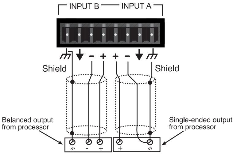
The popular plugable Euro connector is provided for the inputs for each channel. These inputs are balanced electronically, with the terminals marked “+” as the positive amplifier inputs, and the terminals marked “-” as the negative amplifier inputs. The remaining terminals are ground (chassis). If possible, always use two-conductor, shielded cables when interconnecting to the amplifier; connecting the twisted pair to the respective “+” and “-” terminals of each amplifier channel, and the shields to the amplifier ground. When connecting to a CinemAcoustics Cinema Processor, or to any signal processor with a balanced output, connect the “+”, “-”, and ground inputs of the power amplifier to the respective “+”, “-”, and ground outputs of the processor. When connecting the amplifier to a Cinema Processor with a single-ended output, again, use a two-conductor, shielded cable and wire the cable to the amplifier as outlined above. At the processor end, wire the “+” amplifier input to the Cinema Processor “+” output, and wire the “-” amplifier input together with the amplifier shield to the Cinema Processor ground. The amplifier can be wired in an unbalanced configuration using single-conductor, shielded cables by connecting the single conductor to the “+” input of each channel, and connecting the shield to both the “-” input and ground of each channel. A similar connection must be made at the Processor as well. See figure below.
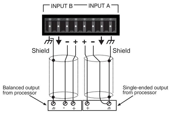
Input A is wired in an unbalanced configuration.
Input A is wired in an unbalanced configuration.
Input B is wired in a balanced configuration.
INSTALLATION AND SETUP
The CinemAcoustics Series of power amplifiers is engineered for durability and high performance in theater installations. Each amplifier is internally cooled by an automatic two-speed fan, and is designed to be installed in a standard 19 inch EIA equipment rack. All input and output connections, as well as level controls, selector switches, and the mains circuit breaker are located on the rear panel. The mains power switch, and the LED indicators for power and SPS activation are located on the front panel. The internal cooling fans pull air in from the rear of the unit and exhaust hot air out the front. When the unit is mounted in an equipment rack, an adequate supply of cool air must be available. Due to the internal fan, it is not necessary to leave a rack space between each amplifier in the stack. Upon power-up, the fan will operate at its low speed and will continue to operate at low speed until sustained, high power operating levels occur. Depending upon signal conditions and amp loading, high-speed fan operation may continue or it may cycle between high and low. The cycling of fan speed during active use is normal. The amplifier thermal sensing circuitry may temporarily shut down the amplifier for a variety of reasons. These reasons include an inadequate supply of cool air, a reduction of air flow due to blockage of the amplifier's inlet or outlet ports, and severe overloading or short circuit of an output. A temporary shutdown will cause the front panel POWER LED to go dark. Depending upon the fault condition, operation could be restored relatively
quickly. In all circumstances, an investigation should be undertaken to determine the cause of the thermal shut down. If the amplifier is not severely overloaded or its outputs shorted, and air flow is normal in and out of the amplifier, steps should be taken to provide a cooler environment for the amplifier, along with any other amplifiers in the same equipment cabinet. As a general rule, the cooler electronic equipment is operated, the longer its useful service life.
BRIDGE MODE
BRIDGE MODE is not recommended in installations where the amplifier is located at a distance from the speaker system. The CA-A540 and CA-A800 amplifiers are equipped with switching to enable BRIDGE operation, should the installation require it. BRIDGE MODE operation is accomplished by placing the mode switch in the "BRIDGE" position, connecting the load across "+" terminal of Channel "A" for the positive and the "+" terminal of Channel "B" for the negative. Use Channel "A" as the input channel. The Channel "B" input is defeated in this mode. In BRIDGE MODE, the minimum recommended load impedance is 8 ohms.
SPS OPERATION
Peavey's patented SPS compression system maximizes the performance of the amplifier by preventing the power amplifier from clipping under maximum power delivery conditions. This compression system is activated by a very unique circuit that senses signal conditions which might overload the amplifier, reducing the amp gain when clipping is imminent. The threshold of compression is near the clip point, so no active compression occurs within the normal dynamic range of the audio signal. By preventing clipping, this feature reduces the possibility of system distortion and possible damage to the loudspeaker. In normal theater applications, it is recommended that the SPS compression feature is placed in ENABLE.
| Characteristics: | CA-A540B | CA-A800B |
| Output Power 1, 2, 3: | ||
| 2 Channel Mode, Stereo | ||
| 4 ohms, 1 kHz at 1% THD | 450 W RMS per channel | 700 W RMS per channel |
| 8 ohms, 1 kHz at 1% THD | 270 W RMS per channel | 400 W RMS per channel |
| Bridge Mode, Mono | ||
| 8 ohms, 1 kHz at 1% THD | 900 W RMS | 1400 W RMS |
| Rated Output Power 1, 2: | ||
| 4 ohms, 20 Hz to 20 kHz, 0.15% THD | 400 W RMS per chan | 625 W RMS per chan |
| 8 ohms, 20 Hz to 20 kHz, 0.1% THD | 240 W RMS per chan | 370 W RMS per chan |
| Slew Rate 3: | ||
| Stereo Mode, each channel | 20 volts per uSec. | 20 volts per uSec. |
| Bridge Mode, mono | 40 volts per uSec. | 40 volts per uSec. |
| Total Harmonic Distortion 2, 3: | ||
| 20 Hz to 20 kHz at rated output, 8 ohms | Less than 0.07% | Less than 0.07% |
| Input Sensitivity and Impedance 4: | ||
| At rated output power, 8 ohms | 1.0 V RMS, 0 dBV | 1.4 V RMS, +3 dBV |
| Balanced inputs | 6.8k ohms per leg | 6.8k ohms per leg |
| Overall system gain per channel | 32.5 dB | 32.5 dB |
| Frequency Response 2, 3: | ||
| ±1dB, 1 W RMS, 8 ohms | 10 Hz to 40 kHz | 10 Hz to 40 kHz |
| ±0.2 dB, at rated output, 8 ohms | 20 Hz to 20 kHz | 20 Hz to 20 kHz |
| Damping Factor 2, 3: | ||
| 8 ohms, 1 kHz | Greater than 300 | Greater than 300 |
| Hum and Noise 1, 2: | ||
| Below rated output power, 8 ohms | 100 dB, unweighted | 100 dB, unweighted |
| Power Consumption 2: | ||
| At rated output power, 8 ohms | 10.3 A at 100 VAC | 15.2 A at 100 VAC |
| 8.6 A at 120 VAC | 12.7 A at 120 VAC | |
| 4.3 A at 220 VAC | 6.4 A at 220 VAC | |
| Cooling System: | Two-speed fan | Two-speed fan |
| SPS Compression System: | Switchable with LED | Switchable with LED |
| Dimensions and Weight: | ||
| Height: | 5.25" (13.3 cm) | 7" (17.8 cm) |
| Width: | 19" (48.3 cm) | 19" (48.3 cm) |
| Depth: | 15" (38.1 cm) | 15" (38.1 cm) |
| Weight: | 45 lbs. (20.5 kg) | 55 lbs. (25.0 kg) |
Notes:
(1) @ 120 VAC, 60 Hz (2) Stereo mode, both channels driven (3) Typical value (4) Input attenuator set FCW
IMPORTANT SAFETY INSTRUCTIONS
WARNING: When using electric products, basic cautions should always be followed, including the following:
- Read these instructions.
- Keep these instructions.
- Heed all warnings.
- Follow all instructions.
- Do not use this apparatus near water. For example, near or in a bathtub, swimming pool, sink, wet basement, etc.
- Clean only with a damp cloth.
- Do not block any of the ventilation openings. Install in accordance with manufacturer's instructions. It should not be placed flat against a wall or placed in a built-in enclosure that will impede the flow of cooling air.
- Do not install near any heat sources such as radiators, heat registers, stoves or other apparatus (including amplifiers) that produce heat.
- Do not defeat the safety purpose of the polarized or grounding-type plug. A polarized plug has two blades with one wider than the other. A grounding type plug has two blades and a third grounding plug. The wide blade or third prong is provided for your safety. When the provided plug does not fit into your inlet, consult an electrician for replacement of the obsolete outlet. Never break off the grounding. Write for our free booklet "Shock Hazard and Grounding". Connect only to a power supply of the type marked on the unit adjacent to the power supply cord.
- Protect the power cord from being walked on or pinched, particularly at plugs, convenience receptacles, and the point they exit from the apparatus.
- Only use attachments/accessories provided by the manufacturer.
- Use only with a cart, stand, tripod, bracket, or table specified by the manufacturer, or sold with the apparatus. When a cart is used, use caution when moving the cart/apparatus combination to avoid injury from tip-over.
- Unplug this apparatus during lightning storms or when unused for long periods of time.
- Refer all servicing to qualified service personnel. Servicing is required when the apparatus has been damaged in any way, such as power-supply cord or plug is damaged, liquid has been spilled or objects have fallen into the apparatus, the apparatus has been exposed to rain or moisture, does not operate normally, or has been dropped.
- If this product is to be mounted in an equipment rack, rear support should be provided.
- Exposure to extremely high noise levels may cause a permanent hearing loss. Individuals vary considerably in susceptibility to noise-induced hearing loss, but nearly everyone will lose some hearing if exposed to sufficiently intense noise for a sufficient time. The U.S. Government's Occupational and Health Administration (OSHA) has specified the following permissible noise level exposures:
Duration Per Day In Hours
8
6
4
3
2
1 1/2
1
1/2
1/4 or less
Sound Level dBA, Slow Response
90
92
95
97
100
102
105
110
115
According to OSHA, any exposure in excess of the above permissible limits could result in some hearing loss. Ear plugs or protectors to the ear canals or over the ears must be worn when operating this amplification system in order to prevent a permanent hearing loss, if exposure is in excess of the limits as set forth above. To ensure against potentially dangerous exposure to high sound pressure levels, it is recommended that all persons exposed to equipment capable of producing high sound pressure levels such as this amplification system be protected by hearing protectors while this unit is in operation.
ESPAÑOL
CA-A540B™ y CA-A800B™
\section*{Characteristicas comunes}
Input A is wired in an unbalanced configuration. Input B is wired in a balanced configuration.
| Characteristics: | CA-A540B | CA-A800B |
| Output Power 1, 2, 3: | ||
| 2 Channel Mode, Stereo | ||
| 4 ohms, 1 kHz at 1% THD | 450 W RMS per channel | 700 W RMS per channel |
| 8 ohms, 1 kHz at 1% THD | 270 W RMS per channel | 400 W RMS per channel |
| Bridge Mode, Mono | ||
| 8 ohms, 1 kHz at 1% THD | 900 W RMS | 1400 W RMS |
| Rated Output Power 1, 2: | ||
| 4 ohms, 20 Hz to 20 kHz, 0.15% THD | 400 W RMS per chan | 625 W RMS per channel |
| 8 ohms, 20 Hz to 20 kHz, 0.1% THD | 240 W RMS per chan | 370 W RMS per channel |
| Slew Rate 3: | ||
| Stereo Mode, each channel | 20 volts per uSec. | 20 volts per uSec. |
| Bridge Mode, mono | 40 volts per uSec. | 40 volts per uSec. |
| Total Harmonic Distortion 2, 3: | ||
| 20 Hz to 20 kHz at rated output, 8 ohms | Less than 0.07% | Less than 0.07% |
| Input Sensitivity and Impedance 4: | ||
| At rated output power, 8 ohms | 1.0 V RMS, 0 dBV | 1.4 V RMS, +3 dBV |
| Balanced inputs | 6.8k ohms per leg | 6.8k ohms per leg |
| Overall system gain per channel | 32.5 dB | 32.5 dB |
| Frequency Response 2, 3: | ||
| ±1dB, 1 W RMS, 8 ohms | 10 Hz to 40 kHz | 10 Hz to 40 kHz |
| ±0.2 dB, at rated output, 8 ohms | 20 Hz to 20 kHz | 20 Hz to 20 kHz |
| Damping Factor 2, 3: | ||
| 8 ohms, 1 kHz | Greater than 300 | Greater than 300 |
| Hum and Noise 1, 2: | ||
| Below rated output power, 8 ohms | 100 dB, unweighted | 100 dB, unweighted |
| Power Consumption 2: | ||
| At rated output power, 8 ohms | 10.3 A at 100 VAC | 15.2 A at 100 VAC |
| 8.6 A at 120 VAC | 12.7 A at 120 VAC | |
| 4.3 A at 220 VAC | 6.4 A at 220 VAC | |
| Cooling System: | Two-speed fan | Two-speed fan |
| SPS Compression System: | Switchable with LED | Switchable with LED |
| Dimensions and Weight: | ||
| Height: | 5.25" (13.3 cm) | 7" (17.8 cm) |
| Width: | 19" (48.3 cm) | 19" (48.3 cm) |
| Depth: | 15" (38.1 cm) | 15" (38.1 cm) |
| Weight: | 45 lbs. (20.5 kg) | 55 lbs. (25.0 kg) |
Notes:
(1) @ 120 VAC, 60 Hz (2) Stereo mode, both channels driven (3) Typical value (4) Input attenuator set FCW
NOTE IMPORTANTE CONCERNANT LA SECURITE
CONSERVEZ CES INSTRUCTIONS!
DEUTSCH
| Characteristics: | CA-A540B | CA-A800B |
| Output Power 1, 2, 3: | ||
| 2 Channel Mode, Stereo | ||
| 4 ohms, 1 kHz at 1% THD | 450 W RMS per channel | 700 W RMS per channel |
| 8 ohms, 1 kHz at 1% THD | 270 W RMS per channel | 400 W RMS per channel |
| Bridge Mode, Mono | ||
| 8 ohms, 1 kHz at 1% THD | 900 W RMS | 1400 W RMS |
| Rated Output Power 1, 2: | ||
| 4 ohms, 20 Hz to 20 kHz, 0.15% THD | 400 W RMS per chan | 625 W RMS per channel |
| 8 ohms, 20 Hz to 20 kHz, 0.1% THD | 240 W RMS per chan | 370 W RMS per channel |
| Slew Rate 3: | ||
| Stereo Mode, each channel | 20 volts per uSec. | 20 volts per uSec. |
| Bridge Mode, mono | 40 volts per uSec. | 40 volts per uSec. |
| Total Harmonic Distortion 2, 3: | ||
| 20 Hz to 20 kHz at rated output, 8 ohms | Less than 0.07% | Less than 0.07% |
| Input Sensitivity and Impedance 4: | ||
| At rated output power, 8 ohms | 1.0 V RMS, 0 dBV | 1.4 V RMS, +3 dBV |
| Balanced inputs | 6.8k ohms per leg | 6.8k ohms per leg |
| Overall system gain per channel | 32.5 dB | 32.5 dB |
| Frequency Response 2, 3: | ||
| ±1dB, 1 W RMS, 8 ohms | 10 Hz to 40 kHz | 10 Hz to 40 kHz |
| ±0.2 dB, at rated output, 8 ohms | 20 Hz to 20 kHz | 20 Hz to 20 kHz |
| Damping Factor 2, 3: | ||
| 8 ohms, 1 kHz | Greater than 300 | Greater than 300 |
| Hum and Noise 1, 2: | ||
| Below rated output power, 8 ohms | 100 dB, unweighted | 100 dB, unweighted |
| Power Consumption 2: | ||
| At rated output power, 8 ohms | 10.3 A at 100 VAC | 15.2 A at 100 VAC |
| 8.6 A at 120 VAC | 12.7 A at 120 VAC | |
| 4.3 A at 220 VAC | 6.4 A at 220 VAC | |
| Cooling System: | Two-speed fan | Two-speed fan |
| SPS Compression System: | Switchable with LED | Switchable with LED |
| Dimensions and Weight: | ||
| Height: | 5.25" (13.3 cm) | 7" (17.8 cm) |
| Width: | 19" (48.3 cm) | 19" (48.3 cm) |
| Depth: | 15" (38.1 cm) | 15" (38.1 cm) |
| Weight: | 45 lbs. (20.5 kg) | 55 lbs. (25.0 kg) |
Notes:
(1) @ 120 VAC, 60 Hz (2) Stereo mode, both channels driven (3) Typical value (4) Input attenuator set FCW
Cinem Acoustics ™ Division
PEAVEY ELECTRONICS CORPORATION LIMITED WARRANTY
Effective Date: November 1, 1998
What This Warranty Covers
Your Peavey CinemAcoustics Warranty covers defects in material and workmanship in CinemAcoustics products purchased and serviced in the U.S.A. and Canada.
What This Warranty Does Not Cover
The Warranty does not cover: (1) damage caused by accident, misuse, abuse, improper installation or operation, rental, product modification or neglect; (2) damage occurring during shipment; (3) damage caused by repair or service performed by persons not authorized by Peavey; (4) products on which the serial number has been altered, defaced or removed; (5) products not purchased from an Authorized CinemAcoustics Dealer.
Who This Warranty Protects
This Warranty protects only the original retail purchaser/end user of the product.
How Long This Warranty Lasts
The Warranty begins on the date of shipment to the CinemAcoustics Dealer. The duration of the Warranty is as follows:
Product Category
Duration
Cinema Processors, Monitors, Power Amplifiers, Electronic
Crossovers, Loudspeakers and MediaMatrix® CPU
(excluding frames) 5 years
Replacement Speaker Components (including speakers,
baskets, drivers, diaphragm replacement kits and
Passive crossovers) purchased as individual
components and all Accessories 1 year
What Peavey Will Do
We will repair or replace (at Peavey's discretion) products covered by warranty at no charge for labor or materials. If the product or component must be shipped to Peavey for warranty service, the consumer must pay initial shipping charges. If the repairs are covered by warranty, Peavey will pay the return shipping charges.
How To Get Warranty Service
(1) Take the defective item to your Authorized CinemAcoustics Dealer or Authorized Peavey Service Center.
OR
(2) Ship the defective item, prepaid, to Peavey Electronics Corporation, International Service Center, 412 Highway 11 and 80 East, Meridian, MS 39301. Include a detailed description of the problem and provide a complete return address.
Limitation of Implied Warranties
ANY IMPLIED WARRANTY, INCLUDING WARRANTYES OF MERCHANTABILITY AND FITNESS FOR A PARTICULAR PURPOSE, ARE LIMITED IN DURATION TO THE LENGTH OF THIS WARRANTY.
Some states do not allow limitations on how long an implied warranty lasts, so the above limitation may not apply to you.
Exclusions of Damages
PEAVEY'S LIABILITY FOR ANY DEFECTIVE PRODUCT IS LIMITED TO THE REPAIR OR REPLACEMENT OF THE PRODUCT, AT PEAVEY'S OPTION. IF WE ELECT TO REPLACE THE PRODUCT, THE REPLACEMENT MAY BE A RECONDITIONED UNIT. PEAVEY SHALL NOT BE LIABLE FOR DAMAGES BASED ON INCONVENIENCE, LOSS OF USE, LOST PROFITS, LOST SAVINGS, DAMAGE TO ANY OTHER EQUIPMENT OR OTHER ITEMS AT THE SITE OF USE, OR ANY OTHER DAMAGES WHETHER INCIDENTAL, CONSEQUENTIAL OR OTHERWISE, EVEN IF PEAVEY HAS BEEN ADVISED OF THE POSSIBILITY OF SUCH DAMAGES.
Some states do not allow the exclusion or limitation of incidental or consequential damages, so the above limitation or exclusion may not apply to you.
This Warranty gives you specific legal rights, and you may also have other rights which vary from state to state.
If you have any questions about this warranty or service received or if you need assistance in locating an Authorized Service Center, please contact the Peavey International Service Center at (601) 483-5365.


Features and specifications subject to change without notice.

PEAVY
Features and specifications subject to change without notice.
Peavey Electronics Corporation • 711 A Street • Meridian • MS • 39301
(601) 483-5376 • FAX (601) 486-1678 • www.peavey.com

- FRONT PANEL CA-A800B
- SPS COMPRESSION ACTIVE LED
- POWER LED
- MAINS POWER SWITCH
- MAINS POWER SOURCE
- NOTE: FOR UK ONLY
- CIRCUIT BREAKER
- OUTPUT MONITOR
- BARRIER STRIP SPEAKER OUTPUTS
- SPS SWITCH
- MODE SWITCH
- INPUT LEVEL
- EURO CONNECTOR INPUTS
- INSTALLATION AND SETUP
- BRIDGE MODE
- SPS OPERATION
- Notes:
- IMPORTANT SAFETY INSTRUCTIONS
- ESPAÑOL
- CA-A540B™ y CA-A800B™
- \section*{Characteristicas comunes}
- NOTE IMPORTANTE CONCERNANT LA SECURITE
- CONSERVEZ CES INSTRUCTIONS!
- DEUTSCH
- Cinem Acoustics ™ Division
- PEAVEY ELECTRONICS CORPORATION LIMITED WARRANTY
- What This Warranty Covers
- What This Warranty Does Not Cover
- Who This Warranty Protects
- How Long This Warranty Lasts
- Product Category
- Duration
- What Peavey Will Do
- How To Get Warranty Service
- Limitation of Implied Warranties
- Exclusions of Damages
Brand : PEAVEY
Model : CA-A540B
Category : Amplifier