
MESSENGER M100 - Guitar amplifier PEAVEY - Free user manual and instructions
Find the device manual for free MESSENGER M100 PEAVEY in PDF.
| Product Type | Portable PA system with amplifier, mixer and speakers |
| Output Power | 50 W per channel (into 4 Ω), 100 W total |
| Frequency Response | 40 Hz – 25 kHz (+0/-3 dB) |
| Distortion | < 0.8% THD |
| Signal-to-Noise Ratio | 85 dB (standard microphone signal) |
| Power Supply | 115 V~ 60 Hz or 230 V~ 50/60 Hz |
| Weight (assembled) | 8.8 kg |
| Included Microphone | PV®i 100 cardioid unidirectional microphone with On/Off switch |
| Inputs | 5 channels: 2 XLR (with phantom power), 1 high-impedance instrument input, 3 line inputs, 2 RCA inputs (for separate tracks) |
| Outputs | 2 speaker outputs (LEFT/RIGHT), 2 auxiliary RCA outputs, 6.35 mm headphone jack output |
| Speakers (per speaker) | 2 x 4" speakers + 1" tweeter, 2-way |
| Mixer | Independent EQ (Bass, Mid, Treble) per channel, Master Volume control, 7-band graphic equalizer with FLS® system |
| Special Function | Track separation (Music/Vocal) on channels 4/5 with inverter, Mid Morph™ EQ |
| Enclosure | High-density polypropylene polymer (carrying case) |
| Safety | Grounded plug, do not expose to moisture, do not open (risk of electric shock) |
| Maintenance | Clean with a dry cloth only |
| Repairability | Have all servicing done by a Peavey authorized technician |
| Box Contents | Mixer, 2 speakers, microphone, cables (speaker, XLR, power), stand |
Frequently Asked Questions - MESSENGER M100 PEAVEY
User questions about MESSENGER M100 PEAVEY
0 question about this device. Answer the ones you know or ask your own.
Ask a new question about this device
Download the instructions for your Guitar amplifier in PDF format for free! Find your manual MESSENGER M100 - PEAVEY and take your electronic device back in hand. On this page are published all the documents necessary for the use of your device. MESSENGER M100 by PEAVEY.
USER MANUAL MESSENGER M100 PEAVEY
Intended to alert the user to the presence of uninsulated "dangerous voltage" within the product's enclosure that may be of sufficient magnitude to constitute a risk of electric shock to persons.
Intended to alert the user of the presence of important operating and maintenance (servicing) instructions in the literature accompanying the product.
CAUTION: Risk of electrical shock — DO NOT OPEN!
CAUTION: To reduce the risk of electric shock, do not remove cover. No user serviceable parts inside. Refer servicing to qualified service personnel.
WARNING: To prevent electrical shock or fire hazard, this apparatus should not be exposed to rain or moisture, and objects filled with liquids, such as vases, should not be placed on this apparatus. Before using this apparatus, read the operating guide for further warnings.

WARNING: When using electrical products, basic cautions should always be followed, including the following:
- Read these instructions.
- Keep these instructions.
- Heed all warnings.
- Follow all instructions.
- Do not use this apparatus near water.
- Clean only with a dry cloth.
- Do not block any of the ventilation openings. Install in accordance with manufacturer's instructions.
- Do not install near any heat sources such as radiators, heat registers, stoves or other apparatus (including amplifiers) that produce heat.
- Do not defeat the safety purpose of the polarized or grounding-type plug. A polarized plug has two blades with one wider than the other. A grounding type plug has two blades and a third grounding plug. The wide blade or third prong is provided for your safety. If the provided plug does not fit into your outlet, consult an electrician for replacement of the obsolete outlet.
- Protect the power cord from being walked on or pinched, particularly at plugs, convenience receptacles, and the point they exit from the apparatus.
- Only use attachments/accessories provided by the manufacturer.
- Use only with a cart, stand, tripod, bracket, or table specified by the manufacturer, or sold with the apparatus. When a cart is used, use caution when moving the cart/apparatus combination to avoid injury from tip-over.
Unplug this apparatus during lightning storms or when unused for long periods of time. - Refer all servicing to qualified service personnel. Servicing is required when the apparatus has been damaged in any way, such as power-supply cord or plug is damaged, liquid has been spilled or objects have fallen into the apparatus, the apparatus has been exposed to rain or moisture, does not operate normally, or has been dropped.
- Never break off the ground pin. Write for our free booklet "Shock Hazard and Grounding." Connect only to a power supply of the type marked on the unit adjacent to the power supply cord.
- If this product is to be mounted in an equipment rack, rear support should be provided.
- Note for UK only: If the colors of the wires in the mains lead of this unit do not correspond with the terminals in your plug, proceed as follows:
a) The wire that is colored green and yellow must be connected to the terminal that is marked by the letter E, the earth symbol, colored green or colored green and yellow.
b) The wire that is colored blue must be connected to the terminal that is marked with the letter N or the color black.
c) The wire that is colored brown must be connected to the terminal that is marked with the letter L or the color red.
- This electrical apparatus should not be exposed to dripping or splashing and care should be taken not to place objects containing liquids, such as vases, upon the apparatus.
- Exposure to extremely high noise levels may cause a permanent hearing loss. Individuals vary considerably in susceptibility to noise-induced hearing loss, but nearly everyone will lose some hearing if exposed to sufficiently intense noise for a sufficient time. The U.S. Government's Occupational Safety and Health Administration (OSHA) has specified the following permissible noise level exposures:
| Duration Per Day In Hours | Sound Level dBA, Slow Response |
| 8 | 90 |
| 6 | 92 |
| 4 | 95 |
| 3 | 97 |
| 2 | 100 |
| 1 1/2 | 102 |
| 1 | 105 |
| 1/2 | 110 |
| 1/4 or less | 115 |
According to OSHA, any exposure in excess of the above permissible limits could result in some hearing loss. Ear plugs or protectors to the ear canals or over the ears must be worn when operating this amplification system in order to prevent a permanent hearing loss, if exposure is in excess of the limits as set forth above. To ensure against potentially dangerous exposure to high sound pressure levels, it is recommended that all persons exposed to equipment capable of producing high sound pressure levels such as this amplification system be protected by hearing protectors while this unit is in operation.
SAVE THESE INSTRUCTIONS!
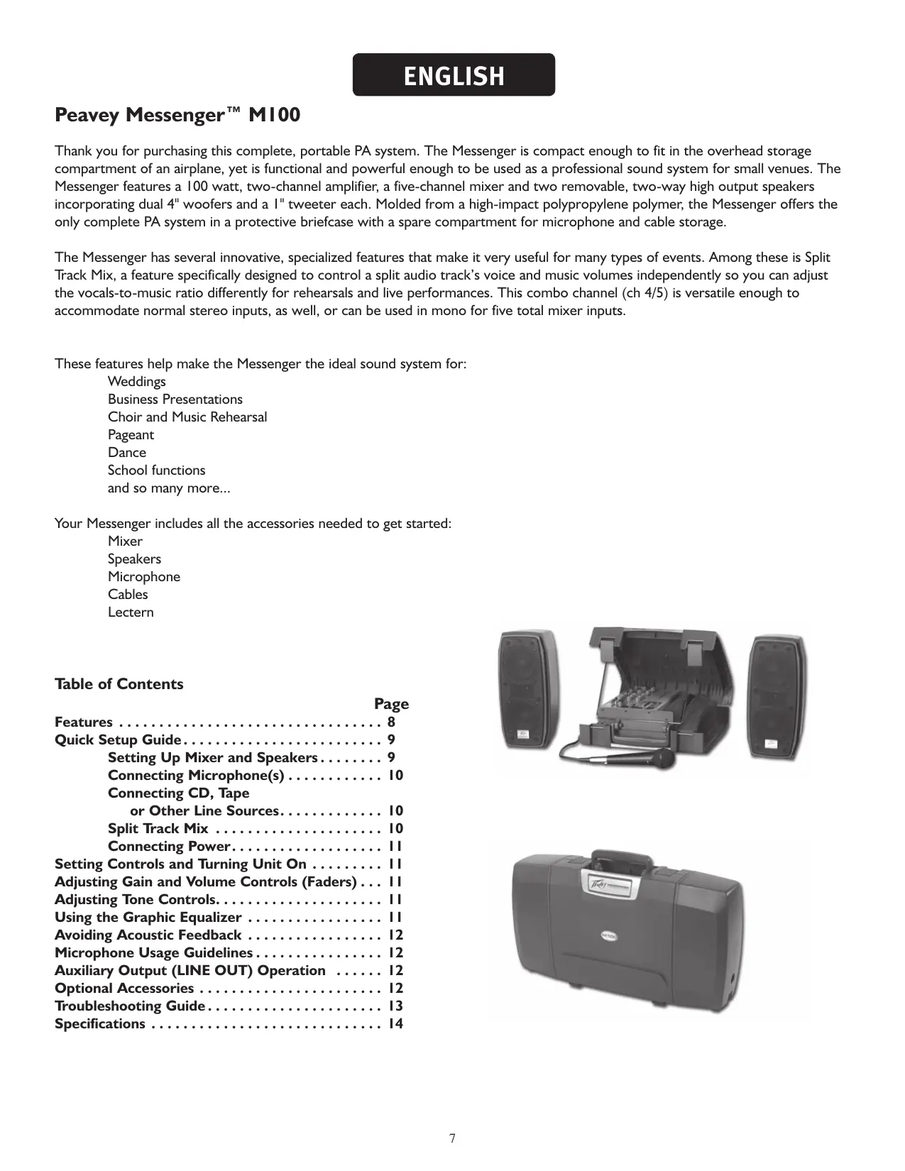
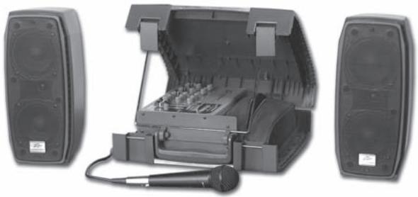
Thank you for purchasing this complete, portable PA system. The Messenger is compact enough to fit in the overhead storage compartment of an airplane, yet is functional and powerful enough to be used as a professional sound system for small venues. The Messenger features a 100 watt, two-channel amplifier, a five-channel mixer and two removable, two-way high output speakers incorporating dual 4'' woofers and a 1'' tweeter each. Molded from a high-impact polypropylene polymer, the Messenger offers the only complete PA system in a protective briefcase with a spare compartment for microphone and cable storage.
The Messenger has several innovative, specialized features that make it very useful for many types of events. Among these is Split Track Mix, a feature specifically designed to control a split audio track's voice and music volumes independently so you can adjust the vocals-to-music ratio differently for rehearsals and live performances. This combo channel (ch 4/5) is versatile enough to accommodate normal stereo inputs, as well, or can be used in mono for five total mixer inputs.
These features help make the Messenger the ideal sound system for:
Weddings
Business Presentations
Choir and Music Rehearsal
Pageant
Dance
School functions
and so many more...
Your Messenger includes all the accessories needed to get started:
Mixer
Speakers
Microphone
Cables
Lectern
Table of Contents
Page
Features 8
Quick Setup Guide. 9
Setting Up Mixer and Speakers. 9
Connecting Microphone(s) 10
Connecting CD, Tape
or Other Line Sources. 10
Split Track Mix 10
Connecting Power. 11
Setting Controls and Turning Unit On . . . . . . I I
Adjusting Gain and Volume Controls (Faders) . . . I I
Adjusting Tone Controls. 11
Using the Graphic Equalizer 11
Avoiding Acoustic Feedback 12
Microphone Usage Guidelines 12
Auxiliary Output (LINE OUT) Operation 12
Optional Accessories 12
Troubleshooting Guide. 13
Specifications 14

Messenger™ MI00 FEATURES
- Molded, high-impact polypropylene carrying case
Convenient briefcase design
Modern ergonomics
Light weight
Interlock speakers
Internal space for cable and microphone storage
- Powered Mixer
100 watts continuous power
Two master speaker channels with independent volume control
Five channels of input with independent volume, low-mid and high EQ controls, including Mid Morph™EQ on channels 1 and 2
Five band graphic EQ featuring FLS® (Feedback Locating System)
Channels 4 and 5 feature Split Track mix with track-swap switch
Two XLR microphone input with phantom power
One high gain instrument/microphone input
Three line-level inputs
Two RCA/phono inputs
Two RCA/phono outputs
Headphone output
Headphone level control
1 14 phone line out
- Two high-efficiency, two-way speakers
Molded polypropylene enclosures
Metal grille
Two 4" high output woofers per speaker
I x I" tweeteter
Molded speaker stand receptacle
- PV®i 100 handheld microphone
Dynamic cardioid
Metal grille
On/Off switch
XLR balanced output
Cables
Two 12' speaker cables
One 15^ XLR balanced microphone cable
One line cord
Quick Setup Guide
THINK SAFETY FIRST!

Much of the setup of the Messenger™ M100 is similar to the setup of other sound systems, and many aspects require plain common sense. Safety should always be your first concern. Always use grounded outlets and three-wire extension cords. Run sound system cables in a way to prevent the danger of tripping, and tape them down where necessary. Place the speaker stands and mixer stand on a solid, level surface. Following these guidelines will help prevent personal injury and equipment damage.
Setting Up Mixer and Speakers
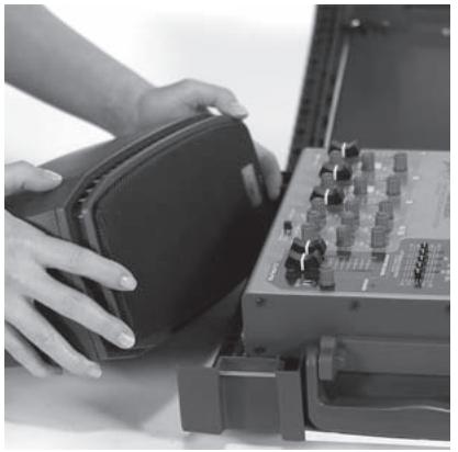
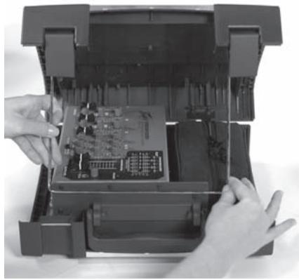
Place the unit on a horizontal surface. Release the latches by lifting up until they disengage. Open the top cover and remove the speakers from the Messenger package.
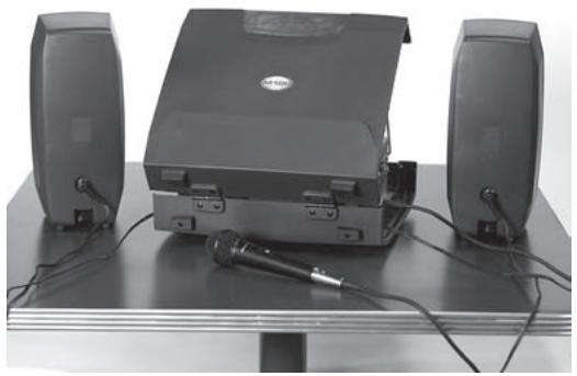
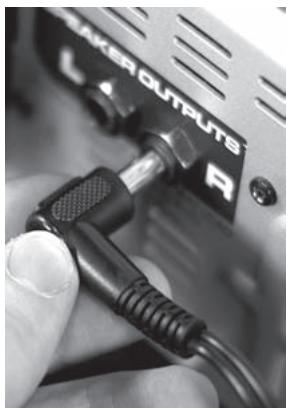
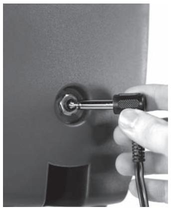
Place speakers on a suitable surface and position them so that they will face toward the audience and away from the microphones. All of the necessary interconnect cables can be found in the convenient zipper pouch. Connect the speaker cables from the jack on the rear of each speaker to the powered mixer, connecting the left speaker to the LEFT OUTPUT and the right speaker to the RIGHT OUTPUT jacks on the side panel of the unit.

Warning! Do not connect additional speakers to the Messenger powered mixer. The included speakers provide the optimal load for the amplifier.
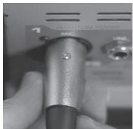
Connecting Microphone(s)
The Messenger™ M100 powered mixer is designed to work with any good-quality, balanced, dynamic or condenser microphone such as the supplied PV®i model. Connect the microphone(s) to the XLR (three-pin) input connectors as shown. When using more than one mic, try to connect them to channels in the same order as they appear on stage to make them easier to identify and control.
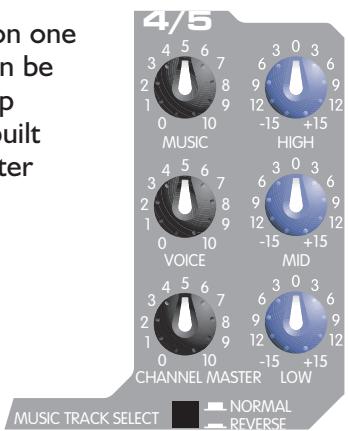
Split Track Mix
Split Track is a featured used on many sing along CDs and cassettes. The vocals are on one side (track) while the music is on the other track. The advantage is that the music can be played without or with only a small amount of vocals during the performance (to help stay on key and beat/que). The Messenger has provisions for the split track feature built in. Channels 4 and 5 have independent volume controls that are controlled by a master channel volume.
For example:
If you want to increase the volume of the pre-recorded material (both tracks) to the level of the other channels (such as a live singer), simply increase the channel 4/5 master volume.
If you want to increase the volume of the music over the vocals, simply increase the music control on ch 4/5 or vice versa for vocals.
This method is much better than a balance or fader because it allows one track to be controlled independently of the other, whereas faders and balance controls reduce one channel while increasing the other.
Since the recording companies who produce these split-track cassettes often use differing production methods, sometimes the music and vocal tracks are swapped—meaning that the Music and Voice controls on channel 4/5 will be respectively backward. What you would expect to hear when adjusting the Music level control would be the voice, and vice versa.
We've included a "swap" button on this channel that allows you to flip-flop the tracks so our Music and Voice level controls always adjust the correct track. If you adjust the Messenger's Music control and notice a change in the vocal volume, for example, then simply press the Music Track Select button. The Music control will then adjust the music, and the Voice control will adjust the vocals.
Connecting CD, Tape or Other Line Sources
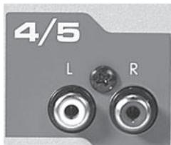
Simply connect the output of the device to the channel 4/5 RCA/phono inputs. Red is right and white is left. For normal audio play, be sure to set the vocal and music volume controls on channel 4/5 to "5." The channel master volume is used to control the volume of the track.
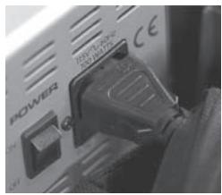
Connecting Power
Before connecting power, make sure that the power switch is in the OFF position.
Connect the IEC power cord to the receptacle on the back panel of the unit, and then to a suitable electrical outlet. If an extension cord is used, be sure that it is a three-wire cord with ground pin intact to preserve the safety ground.
NOTE: FOR U.K. ONLY
If the colors of the wires in the mains lead of this unit do not correspond to the colored markings identifying the terminals in your plug, proceed as follows: (1) The wire that is colored green and yellow must be connected to the terminal that is marked by the letter E, the earth symbol; colored green; or colored green and yellow. (2) The wire that is colored blue must be connected to the terminal that is marked with the letter N or the color black. (3) The wire that is colored brown must be connected to the terminal that is marked with the letter L or
the color red.
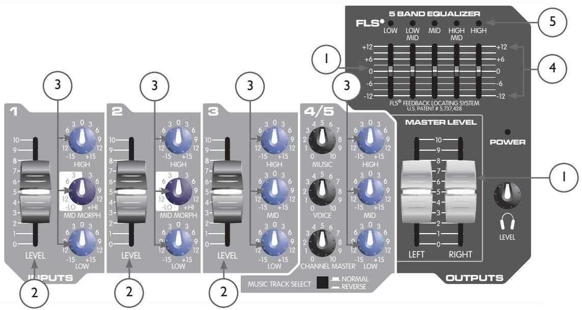
Setting Controls and Turning Unit On (I)
Set MASTER LEVEL controls to the “5” position and all other controls to “0” (all graphic EQ sliders should be on “0”). Turn on power by placing the OFF/ON switch, located adjacent to the IEC cord receptacle, in the ON position.
Adjusting Gain and Volume Controls (Faders) (2)
With the master level at "5," adjust the channel LEVEL controls for desired volume from the speakers. If the desired volume is reached with the channel LEVEL at a low setting (1-3), lower the MASTER LEVEL controls. If the channel LEVEL needs to be set at 9-10 for desired volume, raise the MASTER LEVEL controls. The L and R MASTER LEVEL controls adjust the left and right speakers.
Adjusting Tone Controls (3)
Adjust the channel LOW, MID and HIGH controls as necessary to achieve the desired sound. However, use moderation in setting channel tone controls. The Mid EQ is a unique tone control designed to provide a wide variation of mid-range frequencies. Turning the knob to the left (counterclockwise) adds warmth and smoothness to the voice, while rotating the control to the right (clockwise) enhances vocal intelligibility. Extreme settings of these controls can adversely affect sound quality. Large amounts of boost (+) on these controls can also increase the chance of feedback on microphone inputs.
Using the Graphic Equalizer (4)
Unlike the LOW and HIGH controls on each channel, the five-band graphic equalizer adjusts the tonal balance of all the signals going through the powered mixer. This gives the user greater flexibility in adjusting the sound,
but use moderation in making adjustments.
Avoiding Acoustic Feedback (5)
Acoustic feedback is the loud howl or squealing sound heard through sound systems as the result of sound from the speakers re-entering the microphones. Although it does an excellent job of getting the audience's attention, feedback should be avoided. When dealing with acoustic feedback, it is always best to start looking at the placement of the mics and speakers in the system before resorting to equalization (EQ) adjustments. Make sure that the speakers are positioned to direct the sound toward the audience and away from the microphones. Position mics as close to the sound source as reasonable. Moving the mic closer to the person singing or speaking increases the volume of the sound through the system without having to turn up the gain.
The FLS® (Feedback Locating System) LED indicators (small red lights) are invaluable tools in helping to reduce/eliminate feedback. To use the FLS feature, start by setting all graphic EQ sliders to "0". Then, before the audience arrives, increase the MASTER LEVEL and/or CHANNEL LEVEL until feedback occurs. Note which LED illuminates and slightly lower its corresponding EQ slider. This reduces the volume at the feedback frequency and can be repeated if necessary to improve volume before feedback. However, only lower the sliders in small amounts to avoid adversely affecting sound quality.
Microphone Usage Guidelines
When practical, a single microphone is preferred. Additional microphones will pick up more sound from the speakers and each mic must then be turned down to prevent feedback. However, if you have difficulty balancing the level of different individuals using a single mic, or if you still cannot
get sufficient gain, using more mics can offer an advantage. For example, giving several singers their own microphones allows you to place the microphones much closer to their users. This increases the volume of the sound at the mic and far outweighs any detrimental effect from using multiple mics. It also allows the volume of each mic to be adjusted separately for proper balance. Always have the microphone as close to the instrument or singer's mouth as possible. The singer should hold the microphone directly in front of his/her mouth for best results and to help avoid a "thin" sound. This is why professionals say "eat the mic."
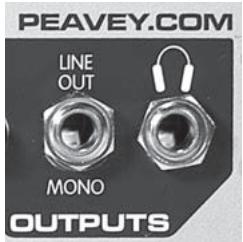
Auxiliary Output (LINE OUT) Operation
The LINE OUT is a line-level output from the mixer that can be used for recording or driving an auxiliary amplifier.
Warning: Connecting a tape machine to the LINE OUT to record while simultaneously connecting the tape machine's output into the mixer inputs can create an electronic feedback loop. Connect only the tape machine's inputs or outputs to the mixer, never both.
Optional Accessories (available from Peavey dealers)
Microphone stand(s)
Additional microphones and cables
Microphone wind screens (grilles)
Additional speaker cables in various lengths
Additional speaker stands in various heights
Audio cables for CD and cassette

Troubleshooting Guide
| Problem | Check | Correction |
| No sound (no power light) | Is power switch on? Is line cord connected to live power outlet? | Turn power switch on. Connect power cord to live outlet. |
| No sound (power light on) | Are MASTER and CHANNEL LEVEL controls up? | Adjust both MASTER and CHANNEL LEVEL controls upward to desired level. Check speaker connections. Turn mic switch on. Check mic or sound source connection. |
| System hum | Are all line cord ground connections made properly on Messenger™ and any auxiliary equipment connected to Messenger? Are all connections secure? Are all interconnect cables shielded, except the speaker cables? Does the system hum when touching microphone? | Turn the volume down on each channel starting with channel 1, working through the mixer channels to determine if the problem is coming from an external audio source, such as a malfunction in that source or a bad recording. We recommend that all units connected to the Messenger be plugged into the same AC power strip. Change the microphone cable and/or microphone. |
| Only one speaker works | Are speaker cable connectors secure? Are both MASTER LEVEL controls up? | Fully insert connector and/or swap speaker cables between left and right speakers and outputs to check for damaged cables. |
| Loud howling or squeal from speakers (known as "feedback" by audio professionals) | If it goes away when the CHANNEL or MASTER volume controls are lowered, it is acoustic feedback. Refer to Avoiding Acoustic Feedback and Using Graphic EQ sections of this manual. | Reduce microphone volume. Reposition microphone behind or farther from speakers. Observe FLS light above EQ and reduce level of that band. |
| Sound is distorted | Is the CHANNEL LEVEL at a very high setting? | Reduce CHANNEL LEVEL and increase MASTER LEVEL. |
Messenger™ MI00 Specifications
Output Power: 50 watts per channel into 4 ohm load
Frequency Response: 40 Hz to 25kHz + 0/ - 3dB measured at I W
Distortion: Less than 0.8% THD at rated output
Signal/Noise Ratio: 85 dB mic input typical
AC Power: 115 VAC 60 Hz or 230 VAC 50/60 Hz
Weight: Assembled: 19.5 lbs. (8.8 kg)
Dimensions: 13.5''H × 24.5''W × 5.25''D (34.3 cm H × 62.2 cm W × 13.3 cm D)
Speakers: Woofer 4'' (100 mm) Dynamic I" (25 mm) Horn Tweeter
Microphone: Dynamic, Cardioid (Unidirectional)
DEUTSCH
Peavey Messenger™ M100
Dynamic I" (25 mm) Hochtoner
Connection Microphone(s) 26
Connector le(s) microphone(s)
This method is much better than a balance or fader because it allows one track to be controlled independently of the other, whereas faders and balance controls reduce one channel while increasing the other.
Dimensions: (34.3 cm H × 62.2 cm L × 13.3 cm P)
Enceintes: 2 haut-parleurs de 4" (100 mm)
tweeter de 1" (25 mm)
What This Warranty Covers
Your Peavey Warranty covers defects in material and workmanship in Peavey products purchased and serviced in the U.S.A. and Canada.
What This Warranty Does Not Cover
The Warranty does not cover: (1) damage caused by accident, misuse, abuse, improper installation or operation, rental, product modification or neglect; (2) damage occurring during shipment; (3) damage caused by repair or service performed by persons not authorized by Peavey; (4) products on which the serial number has been altered, defaced or removed; (5) products not purchased from an Authorized Peavey Dealer.
Who This Warranty Protects
This Warranty protects only the original retail purchaser of the product.
How Long This Warranty Lasts
The Warranty begins on the date of purchase by the original retail purchaser. The duration of the Warranty is as follows:
| Product Category | Duration |
| Guitars/Basses, Amplifiers, Pre-Amplifiers, Mixers, Electronic Crossovers and Equalizers | 2 years * (+ 3 years) |
| Drums | 2 years * (+ 1 year) |
| Enclosures | 3 years * (+ 2 years) |
| Digital Effect Devices and Keyboard and MIDI Controllers | 1 year * (+ 1 year) |
| Microphones | 2 years |
| Speaker Components (incl. speakers, baskets, drivers, diaphragm replacement kits and passive crossovers) and all Accessories | 1 year |
| Tubes and Meters | 90 days |
[Denotes additional warranty period applicable if optional Warranty Registration Card is completed and returned to Peavey by original retail purchaser within 90 days of purchase.]
What Peavey Will Do
We will repair or replace (at Peavey's discretion) products covered by warranty at no charge for labor or materials. If the product or component must be shipped to Peavey for warranty service, the consumer must pay initial shipping charges. If the repairs are covered by warranty, Peavey will pay the return shipping charges.
How To Get Warranty Service
(1) Take the defective item and your sales receipt or other proof of date of purchase to your Authorized Peavey Dealer or Authorized Peavey Service Center. OR
(2) Ship the defective item, prepaid, to Peavey Electronics Corporation, International Service Center, 412 Highway 11 & 80 East, Meridian, MS 39301 or Peavey Canada Ltd., 95 Shields Court, Markham, Ontario, Canada L3R 9T5. Include a detailed description of the problem, together with a copy of your sales receipt or other proof of date of purchase as evidence of warranty coverage. Also provide a complete return address.
Limitation of Implied Warranties
ANY IMPLIED WARRANTY, INCLUDING WARRANTY OF MERCHANTABILITY AND FITNESS FOR A PARTICULAR PURPOSE, ARE LIMITED IN DURATION TO THE LENGTH OF THIS WARRANTY.
Some states do not allow limitations on how long an implied warranty lasts, so the above limitation may not apply to you.
Exclusions of Damages
PEAVEY'S LIABILITY FOR ANY DEFECTIVE PRODUCT IS LIMITED TO THE REPAIR OR REPLACEMENT OF THE PRODUCT, AT PEAVEY'S OPTION. IF WE ELECT TO REPLACE THE PRODUCT, THE REPLACEMENT MAY BE A RECONDITIONED UNIT. PEAVEY SHALL NOT BE LIABLE FOR DAMAGES BASED ON INCONVENIENCE, LOSS OF USE, LOST PROFITS, LOST SAVINGS, DAMAGE TO ANY OTHER EQUIPMENT OR OTHER ITEMS AT THE SITE OF USE, OR ANY OTHER DAMAGES WHETHER INCIDENTAL, CONSEQUENTIAL OR OTHERWISE, EVEN IF PEAVEY HAS BEEN ADVISED OF THE POSSIBILITY OF SUCH DAMAGES. Some states do not allow the exclusion or limitation of incidental or consequential damages, so the above limitation or exclusion may not apply to you.
This Warranty gives you specific legal rights, and you may also have other rights which vary from state to state.
If you have any questions about this warranty or service received or if you need assistance in locating an Authorized Service Center, please contact the Peavey International Service Center at (601) 483-5365 / Peavey Canada Ltd. at (905) 475-2578.
FEATURES AND SPECIFICATIONS SUBJECT TO CHANGE WITHOUT NOTICE.

Features and specifications subject to change without notice.
Peavey Electronics Corporation • 711 A Street • Meridian • MS • 39301
(601) 483-5365 • FAX (601) 486-1278 • www.peavey.com
EX000013
- SAVE THESE INSTRUCTIONS!
- Table of Contents
- Messenger™ MI00 FEATURES
- Quick Setup Guide
- THINK SAFETY FIRST!
- Setting Up Mixer and Speakers
- Connecting Microphone(s)
- Split Track Mix
- Connecting CD, Tape or Other Line Sources
- Connecting Power
- NOTE: FOR U.K. ONLY
- Setting Controls and Turning Unit On (I)
- Adjusting Gain and Volume Controls (Faders) (2)
- Adjusting Tone Controls (3)
- Using the Graphic Equalizer (4)
- Avoiding Acoustic Feedback (5)
- Microphone Usage Guidelines
- Auxiliary Output (LINE OUT) Operation
- Optional Accessories (available from Peavey dealers)
- Messenger™ MI00 Specifications
- DEUTSCH
- Peavey Messenger™ M100
- Connector le(s) microphone(s)
- What This Warranty Covers
- What This Warranty Does Not Cover
- Who This Warranty Protects
- How Long This Warranty Lasts
- What Peavey Will Do
- How To Get Warranty Service
- Limitation of Implied Warranties
- Exclusions of Damages
Brand : PEAVEY
Model : MESSENGER M100
Category : Guitar amplifier