CEL-2A - Professional audio equipment PEAVEY - Free user manual and instructions
Find the device manual for free CEL-2A PEAVEY in PDF.

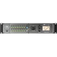
| Product Type | Dual compressor/expander/limiter (stereo or dual mono) |
| Power Supply | Mains via IEC connector, voltage per unit (typ. 100-240 V AC, 50/60 Hz) |
| Power Consumption | Not specified, typical for a 1U rack |
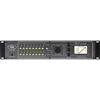
| Inputs | XLR and 1/4" TRS balanced, line impedance |
| Outputs | XLR and 1/4" TRS balanced, line level |
| Insert Connectors | 1/4" TRS (tip input, ring output) per channel |
| Side-chain | Stereo TRS jack for external insert (send/return) |
| Main Functions | Expansion, compression (Soft Knee), limiting (infinite ratio), de-essing, ducking, side-chain high-pass filter |
| Display | 12-LED VU meters (input/output level and gain reduction) |
| Bypass | Yes, with bi-color LED (green normal, red bypass) |
| Stereo Link | Yes, RMS summation of both channels, channel A controls master |
| Frequency Response | Not specified, typical for professional audio equipment (20 Hz - 20 kHz) |
| Distortion | Very low due to VCA and RMS circuits |
| Signal-to-Noise Ratio | Excellent, optimized by level adjustment |
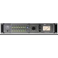
| Dimensions | Standard 1U rack unit (44.5 mm × 483 mm wide), depth not specified |
| Weight | Not specified, typical ~2-3 kg |
| Maintenance and Cleaning | Clean with a dry cloth; refer any repairs to a qualified Peavey technician |
| Safety | Do not expose to rain or moisture; disconnect before servicing |
| Spare Parts and Repairability | No user-serviceable parts; contact an authorized Peavey repair center |
Frequently Asked Questions - CEL-2A PEAVEY
User questions about CEL-2A PEAVEY
0 question about this device. Answer the ones you know or ask your own.
Ask a new question about this device
Download the instructions for your Professional audio equipment in PDF format for free! Find your manual CEL-2A - PEAVEY and take your electronic device back in hand. On this page are published all the documents necessary for the use of your device. CEL-2A by PEAVEY.
USER MANUAL CEL-2A PEAVEY
Intended to alert the user to the presence of uninsulated "dangerous voltage" within the product's enclosure that may be of sufficient magnitude to constitute a risk of electric shock to persons.

Intended to alert the user of the presence of important operating and maintenance (servicing) instructions in the literature accompanying the product.
CAUTION: Risk of electrical shock — DO NOT OPEN!
CAUTION: To reduce the risk of electric shock, do not remove cover. No user serviceable parts inside.
Refer servicing to qualified service personnel.
WARNING: To prevent electrical shock or fire hazard, do not expose this appliance to rain or moisture. Before using this appliance, read the operating guide for further warnings.

WARNING: When using electrical products, basic cautions should always be followed, including the following:
- Read these instructions.
- Keep these instructions.
- Heed all warnings.
- Follow all instructions.
- Do not use this apparatus near water.
- Clean only with a dry cloth.
- Do not block any of the ventilation openings. Install in accordance with manufacturer's instructions.
- Do not install near any heat sources such as radiators, heat registers, stoves or other apparatus (including amplifiers) that produce heat.
- Do not defeat the safety purpose of the polarized or grounding-type plug. A polarized plug has two blades with one wider than the other. A grounding type plug has two blades and a third grounding plug. The wide blade or third prong is provided for your safety. If the provided plug does not fit into your outlet, consult an electrician for replacement of the obsolete outlet.
- Protect the power cord from being walked on or pinched, particularly at plugs, convenience receptacles, and the point they exit from the apparatus.
- Note for UK only: If the colors of the wires in the mains lead of this unit do not correspond with the terminals in your plug, proceed as follows:
a) The wire that is colored green and yellow must be connected to the terminal that is marked by the letter E, the earth symbol, colored green or colored green and yellow.
b) The wire that is colored blue must be connected to the terminal that is marked with the letter N or the color black.
c) The wire that is colored brown must be connected to the terminal that is marked with the letter L or the color red.
- Only use attachments/accessories provided by the manufacturer.
- Use only with a cart, stand, tripod, bracket, or table specified by the manufacturer, or sold with the apparatus. When a cart is used, use caution when moving the cart/apparatus combination to avoid injury from tip-over.
- Unplug this apparatus during lightning storms or when unused for long periods of time.
- Refer all servicing to qualified service personnel. Servicing is required when the apparatus has been damaged in any way, such as power-supply cord or plug is damaged, liquid has been spilled or objects have fallen into the apparatus, the apparatus has been exposed to rain or moisture, does not operate normally, or has been dropped.
- Never break off the ground pin. Write for our free booklet "Shock Hazard and Grounding." Connect only to a power supply of the type marked on the unit adjacent to the power supply cord.
- If this product is to be mounted in an equipment rack, rear support should be provided.
- Exposure to extremely high noise levels may cause a permanent hearing loss. Individuals vary considerably in susceptibility to noise-induced hearing loss, but nearly everyone will lose some hearing if exposed to sufficiently intense noise for a sufficient time. The U.S. Government's Occupational and Health Administration (OSHA) has specified the following permissible noise level exposures:
| Duration Per Day In Hours | Sound Level dBA, Slow Response |
| 8 | 90 |
| 6 | 92 |
| 4 | 95 |
| 3 | 97 |
| 2 | 100 |
| 1 1/2 | 102 |
| 1 | 105 |
| 1/2 | 110 |
| 1/4 or less | 115 |
According to OSHA, any exposure in excess of the above permissible limits could result in some hearing loss. Ear plugs or protectors to the ear canals or over the ears must be worn when operating this amplification system in order to prevent a permanent hearing loss, if exposure is in excess of the limits as set forth above. To ensure against potentially dangerous exposure to high sound pressure levels, it is recommended that all persons exposed to equipment capable of producing high sound pressure levels such as this amplification system be protected by hearing protectors while this unit is in operation.
SAVE THESE INSTRUCTIONS!
ENGLISH
CEL-2A™
Dual Compressor/Expander/Limiter
Thank you for purchasing the CEL-2A. You'll find plenty of features and versatility in this single-rack space, dual compressor. The CEL-2A can be operated as either two independent compressors or as a linked, stereo compressor with true RMS summing. High-quality, voltage-controlled amplifier (VCA) and RMS-rectifier integrated circuits are used to maintain low distortion and excellent noise performance.
This unit has fully-balanced inputs and outputs, with XLR and 1/4 " jack connections. A special "one cable" in/out 1/4 " TRS jack has also been provided to allow the use of a standard 1/4 " stereo cable to directly connect the CEL-2A to an insert jack of a mixer.
Soft-knee topology is used for the compressor and expander functions to provide smooth transition curves. (When the circuits become active, the gain change is phased in rather than instantaneously applied.) This causes the dynamic changes to be less obvious and more aesthetically pleasing as well as being easier to adjust for the desired result.
The "downward" expander section has threshold and ratio adjustments to allow it to be used for noise reduction (slight ratio) or a gate (high ratio). An LED lights when it is active. The compressor has attack and release controls in addition to threshold and ratio controls for complete versatility. Any level lost due to compression can be made up by the gain control. The limiter is an infinite ratio compressor that keeps the output from exceeding a level set by its threshold control and has only one adjustment. It is totally independent of the compressor's settings and can be used to stop peaks from getting through when only mild compression (a low ratio setting in the compressor section) is desired. It has its own LED to indicate when it has been activated.
Each section (expander, compressor or limiter) can be set so that it is disabled either by a threshold or ratio adjustment. A side-chain insert (with its own enable switch) in the detector path allows manipulation or replacement of the detector signal. Built into the side-chain are two selectable filters: a low-cut filter which reduces low frequency modulation from the detector path and a "de-ess" filter, which will assist in removing sibilance (overstressing of the s, c and k consonants). These functions can be used simultaneously, either by themselves or with an external signal applied at the rear jack.
A dual-mono/stereo link switch sums the RMS detected signal levels of each channel together to accurately represent the stereo signal's amplitude. This voltage is used to control both VCAs. In this mode, only the controls associated with Channel A function. The gain meter of Channel B follows Channel A's.
There is a twelve-segment LED array that shows the amount of gain reduction and a ten-segment array to indicate either the output or input levels. By watching the gain reduction meter and the output meter, adjustments are readily apparent and easy to set.
A bypass switch disengages all functions and passes the input signal to the output without processing it. It is configured to allow the unit to be used as an unbalanced to balanced converter even when bypassed, so power is always required.
Please read this guide carefully to ensure your personal safety as well as the safety of your equipment.
Features
- compressor, limiter and expander functions simultaneously available
- operates as two, independent compressors or a linked stereo compressor with true RMS summing
- one cable (per channel) operation with mixer TRS inserts
- full gain reduction monitoring of expander, compressor and limit processors
- fully balanced inputs and outputs (XLR and TRS 1/4")
- soft-knee topology providing smooth transition curves
- expander section includes threshold and ratio adjustments
- side-chain insert
- built-in de-esser and low-cut side chain filters
- low noise circuitry
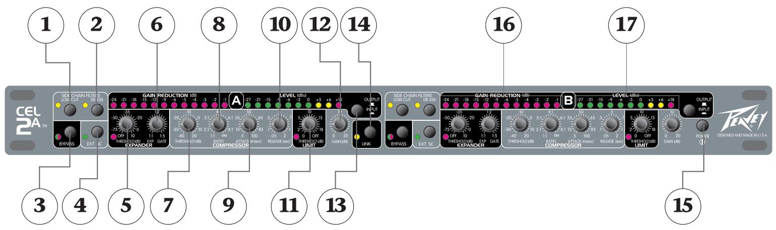
(1) Low-cut filter
An 18 dB filter with a cut-off frequency of 200 Hz in the side chain (only), does not filter the audio path. This filter is used to prevent low frequency modulation (which often appears as pumping and breathing) by reducing the affects of wind, stage and handling noise. If it is used with bass-only program material, it could prevent the compressor from seeing the source. It does not require the external side-chain to be enabled.
(2) De-esser filter
This filter is named after its function—it helps remove the hissing in the "sss." By increasing the compressor's sensitivity to high frequency components (as in the s, c and k consonants) it acts more aggressively on these sounds without lowering normal speech levels. For this circuit to function properly, the compressor's attack and release controls must be set to respond very quickly (minimum settings) and a mid- to high-compression ratio must be used. It does not require the external side-chain to be enabled.
(3) Bypass
To disable signal processing each channel of the CELO can be bypassed. The internal circuitry maintains input and output isolation even when bypassed, allowing the unit to function as an unbalanced to balanced converter if needed. To provide this feature, power must be on even when the unit is bypassed. A two-color status LED is provided to show the channel's condition. When the unit is operating the LED is green (processing happening), when the LED is red, the unit is bypassed.
(4) External Side-chain Enable
The side-chain is an insert loop inserted into the detector path so that the signal sent to the detector can be rerouted through an external device or replaced altogether. This switch enables the rear panel jack and external processing. It has no affect on the side-chain low-cut or de-ess filters, which operate independently, but any signal applied to the external jack will pass through them if they are enabled.
(5) Expander Threshold
This sets the level at which the downward expander begins operation. If the input signal drops below the thresholds set point, the expander fades it out according to the slope (ratio) set by the ratio control. The soft-knee design smooths the transition from off to active by dynamically shifting the slope through the transition point. The attack and release times are preset. An LED has been provided to show expansion activity.
(6) Expander Ratio (Gate)
The expander ratio is determined by dividing the input level by the output level. A ratio of 1:5 signifies that the output level has dropped five times as fast as the input (downward expanded). Ratios of 1:1.2 to 1:2 are typically used to eliminate background noise and to dampen room reverberations. Higher ratios are used when gating is required. Expansion is eliminated when the ratio is set to 1:1.
(7) Compressor Threshold
This sets the point that compression action begins. Any signal above this threshold will be compressed at the amount set by the ratio control. If it drops below this point, the compressor has no affect. At the maximum setting, the compressor will be out of circuit for all signals except very high peaks. At the minimum setting, the source will be continuously compressed.
(8) Compressor Ratio
This varies the amount of compression. It is the ratio of the input level to the output level. A ratio of 4:1 signifies that the input level has increased four times as fast as the output (the dynamic range is compressed by a factor of 4). If the ratio is 1:1 the output exactly tracks the input and there is no compression. Ratios of 2:1 to 4:1 are typically used for vocals and musical instruments. High ratios provide a soft limiting function, since the compressor uses a soft-knee design. To disable compression, set the ratio to 1:1.
(9) Compressor Attack
Sets the speed at which the compressor circuit responds to an increase in the input level. Minimum settings allow it to act quickly so that fast transients do not get through. High settings slow down the response time to let the signal settle before acting upon it. (Useful for those situations when you want percussive attacks but still need compression.)
(10) Compressor Release
Sets the time which the compressor circuit takes to track the input after a drop in level. Low settings will cause the compressor to follow the signal closely so that rapid input changes will not be lost during compression. Higher settings smooth out compression effects.
(11) Limiter Threshold
The limiter is an infinite ratio compressor. The threshold control defines the point that absolute limiting begins. The limit LED will light when this threshold has been exceeded. To disable limiting, set this control to maximum.
(12) Gain
Adjusts the post-processing gain to make up for compression loss. It does not adjust the input level. The input levels should be set by the source equipment to o dBu or +4 dBu for best noise performance. The input and output levels are monitored by an LED meter so that gain can be applied to the signal. A twelve-segment LED array tells how much gain reduction is being applied to the signal. If this meter is not active there is no change to the input signal. It is very useful for making adjustments, since the action of all controls is easily seen.
(13) Input/Output Level Meter Switch
This is a peak indicating meter that is connected to either the output or the input. When in the out position, the LEDs display the output and when depressed, the LEDs display the input.
(14) Stereo Link
If the compressor is to be used with stereo signals, the link switch should be pressed. This gives true RMS summing for an accurate representation of the levels of Channel A and B and locks them together to maintain the stereo image during processing. When the link switch is pressed, Channel A's controls become the masters and affect both channels. The controls for Channel B are disabled. The meters of Channel B will still reflect the VCA and input/output levels, just as in the dual-mono mode.
(15) Power Switch
Power is applied to the unit when this switch is pressed.
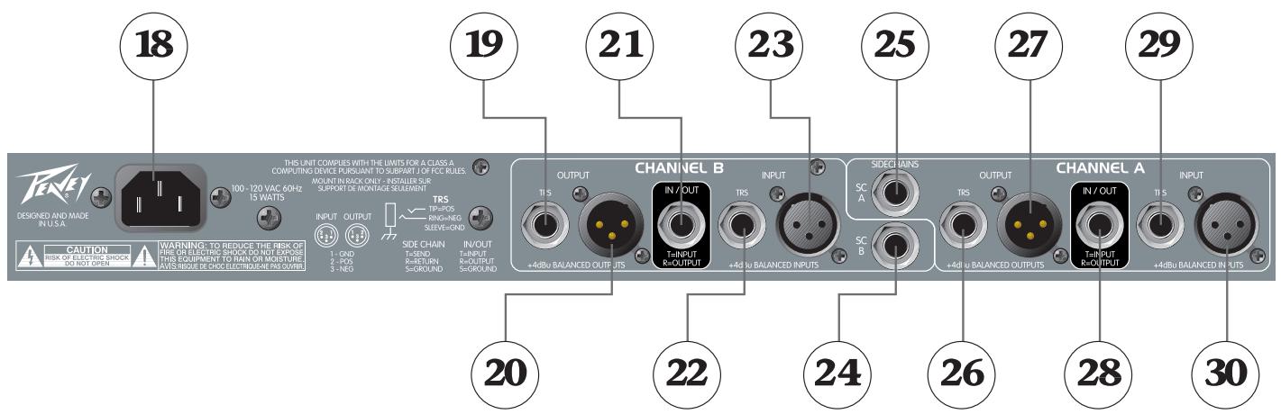

(18) AC Mains Input
Connect the appropriate line cord to this connector to provide power to the unit. Damage to the equipment may result if improper line voltage is used. Operate only with the specified AC input voltage applied.
(19, 20, 26, 27) Balanced Outputs
XLR and 1/4 "TRS, servo-balanced, line level outputs. Pin 2 (tip) is the positive phase, pin 3 (ring) is the negative phase. If unbalanced outputs are used the negative phase must be grounded. The XLR and 1/4 "TRS jacks are wired directly in parallel.
(21, 28) Input/Output
This unbalanced 1 / 4 TRS jack has both input and output signals. It is configured so that a standard (not cross wired) stereo shielded cable can be used to plug into the TRS insert of a mixer. (The tip is input, ring is output, which match the insert jack wiring of all current Peavey mixers.)
(22, 23, 29, 30) Balanced Inputs
XLR and 1/4 "TRS balanced inputs for line level inputs. Pin 2 (tip) is the positive phase, pin 3 (ring) is the negative phase. If unbalanced inputs are used the negative phase must be grounded. The XLR and 1/4 "jacks are wired directly in parallel.
(24, 25) Detector Side-chain Insert
A 1/4" stereo (TRS) jack which allows an external device to be inserted into the detector's signal path or an alternate signal can be brought in to be used as a key. The tip has the send signal and the ring is the return input. A switch in the jack normally connects the return (ring) to the send (tip) until a plug is inserted. To use as a ducker, apply the controlling signal to the ring connection and adjust the compressor controls to set the amount and threshold.
Setting the Controls
If you are starting from scratch or have something out of whack and do not know exactly what to adjust, begin by setting the controls so that all functions are disabled. Here are the control positions for this:
| Expander | |
| Threshold | min (off) |
| Ratio | min (1:1) |
| Compressor | |
| Threshold | max (+20 dB) |
| Ratio | min (1:1) |
| Attack | center (50 mSec) |
| Release | center (.5 sec) |
| Limit | max (off) |
| Gain | min (0 dB) |
| Low Cut | out (off) |
| De-ess | out (off) |
Naturally, the controls that need to be adjusted depend on what you want to accomplish. Below are some suggestions to get you up and running. Follow the order listed and leave the controls in the disabled positions if that particular function is not required.
- Determine the maximum output level and adjust the Limit Threshold so that, at the loudest peaks, the output level never exceeds this point. (The action of the limiter can be seen on the Gain Reduction Meter. If it never activates, there will be no LED activity.) One way to do this is to deliberately increase the input to the compressor until the desired maximum level is exceeded, then turn the Limit Threshold control counter-clockwise until it limits it to the correct gain. Reset the input level to the nominal setting (o dBu average). An alternate method is to turn down the Limit Threshold until gain reduction has just occurred. Then, adjust the output level control to set the desired output level. If the limit is set too low, the signal will lose its dynamic range and the sound will be squashed.
- To set up a noise gate, first turn the Expander Ratio control fully clockwise (1:5). During quiet passages of the source (between songs, when the mics are not being used, etc.) adjust the Expander Threshold clockwise until gain reduction is indicated (a reduction of -9 dB is a good starting point). Re-adjust the Expander Ratio to set the desired gating action when the source changes from noise to signal. A setting of 1:1.2 has little action and can tolerate higher threshold settings without coloring the sound; 1:5 will cause an abrupt turn on and off when the signal changes and will probably need a lower threshold setting to prevent the signal from dropping off when you don't want it to. You may need to go back and adjust the threshold after the ratio has been changed since the soft-knee circuitry has more affect at lower ratios, making the transition point less obvious.
-
For typical voice compression, set the Compressor Ratio control to 4:1 (a range of 2:1 to 6:1 is common) and adjust the Compressor Threshold until the desired amount of gain reduction is seen on the meter. This is a personal preference but continuous gain reduction greater than -9 dB (especially with higher ratios) could be excessive and create pumping/breathing artifacts as the signal rises and falls. Lower ratios will have a more gentle effect. Adjust the Attack control to low values to suppress leading-edge spikes or to high values to let them through (often used to pass through the click of a drum hit). The Release control is adjusted to smooth the transition as it comes out of compression. Too quick a release will cause the signal to sound artificial. A fast attack and a short release time will cause the compressor to track the signal very closely (and keep the dynamic range very limited), but can severely impact the sound. (A 50 millisecond attack and a .5 second release time are good starting points.)
-
To use as a de-esser, engage the side-chain De-ess filter. Set the Attack and Release controls at minimum and the Compressor Ratio to 4:1. Speak or sing a phrase with heavy sibilance (lots of "Ss") and adjust the Compressor Threshold until 6–9 dB of gain reduction occurs at the peaks. This will get you close to where you need to be. Modify the settings for more or less reduction. If the ratio is too high or the threshold is too low the compression may be exaggerated, causing the material to drop excessively in volume (duck) during sibilance.
- When heavy bass or low frequency noise causes the compressor to drop levels unnecessarily, the side-chain Low-cut filter can be used. When activated, the Compressor Threshold should be reset since a large portion of the signal usually contains low frequency components. The bass will have less affect on the compressor and the signal will sound more natural. If the source contains only bass frequencies, this may prevent the compressor from working at all and the bass will pass through unchanged.
- After all the settings are made, adjust the Gain control for a 0 dBu (or +4 dBu) average on the output meter.
CEL-2A
SPECIFICATIONS
| Control | Adjustment Range |
| Expander Threshold | -80 dBu to +10 dBu |
| Expander Ratio | 1:1 (off) to 1:5 (gate) |
| Expander Attack | .5 mSec (fixed) |
| Expander Release | 200 mSec (fixed) |
| Compressor Threshold | -40 dBu to +20 dBu |
| Compressor Ratio | 1:1 (off) to infinite:1 (limit) |
| Compressor Attack | .5 mSec to 100 mSec |
| Compressor Release | .05 sec to 2 sec |
| Limiter Threshold | o dBu to +20 dBu (off) |
| Limiter Attack | .5 mSec (fixed) |
| Limiter Release | 50 mSec (fixed) |
| Gain Recovery | o dB to +20 dB |
| Input | Impedance | Connector |
| XLR (balanced) | 20K oHms | XLR Pin 1 = ground Pin 2 = positive phase Pin 3 = negative phase |
| TRS (balanced) | 20K oHms | 1/4" Sleeve = ground Tip = positive phase Ring = negative phase |
| 1/4" In/Out Phone (unbalanced) | 10K oHms | 1/4" phone tip = input ring = output (see control functions above) |
THD: Less than 0.1%, 20 Hz-20 kHz (10 Hz-80 kHz BW)
Signal-to-noise: 97 dB (o dBu reference level)
Frequency Response: 20 Hz-64 kHz (+o dB/-1 dB)
Output Impedance: 100 ohms (XLR and 14 )
Meters: Two 12-segment LED arrays, two 10-segment LED arrays, two activity LEDs
Dimensions: 19"W x 9.25"D x 1.75"H
Weight: 7.2 lbs (3.3 kg)
Power Requirements: Domestic: 100-120 VAC 50/60 Hz (15 watts nominal); Export: 230 VAC 50/60 Hz (15 watts nominal)
CEL-2A Application Guide
The key to successfully using a compressor is to visualize the signal's envelope and then create a scheme that closely tracks that flow. Thus, a kick drum, with its sharp attack and fast decay, requires a tracing envelope with a quick attack, somewhat heavy clamping, and fast release of the compressed signal. The CEL-2A has enough parameter control to "dial-in" almost any desired configuration. With the unique architecture of the CEL-2A, the gate, compressor and limiter act independently on the signal, then return the processed signal to the output, thereby insuring the shortest, cleanest path. These settings typically work best on individual instruments brought into the CEL-2A and returned through a channel insert. It is worth noting, personal taste is an integral part of any audio endeavor, including compression, so feel free to adjust these settings for preference.
Lead Vocal
Less is more here, with the primary job of the CEL-2A being a non-invasive massaging of the vocalist's dynamic range so it fits within the system and venue capacities. Thus, the compressor's threshold can be set high enough (-5) to give the vocalist complete dynamic freedom for most of the song, engaging the unit only during loud passages and sharp transients. A ratio of 3:1 should suffice, but gifted vocalists may need more clamping at 4:1. Setting the attack control to 50mS will allow the singer's unique timbre to punch through while keeping attacks from becoming destructive. Conversely, a release setting around .4S will smooth phrases without removing their vitality. For the expander, it may be wise to leave it disengaged since soft passages may be lost if the background noise forces a high threshold setting. However, it is worth an attempt to engage the gate to bring the vocalist mentally closer to the audience with reduced room encroachment. Try setting the threshold while the mic is silent by raising its value until its LED lights, indicating it is shut. Next, place the expansion gate control at the nominal 1:2 position and watch the LED ladder above for a reduction around -6 (gentle shutting) to -12 (hard slam). During soundcheck, reduce or increase the expansion setting so the gate shuts enough between passages to prevent background noise from entering the mic while still allowing soft passages to be heard. If the vocalist is using a hyper-cardioid condenser mic, there may be excessive sibilance (overstressing of the "s" and "c" consonants) in the system. The CEL-2A features a new de-essing circuit that is engaged by a simple press of the associated switch. This circuit is designed to remove the annoying sibilance without destroying the articulation necessary for comprehension. At the lower end of the frequency scale, the low-cut filter should be activated when the vocal in use contains little bass information, such as a soprano, alto, tenor or lead. Removing unneeded information will dramatically improve the quality of the vocal and make the engineer's job much easier. The final adjustment is to the limiter, the safety valve of the signal. For lead vocals, set the control to 15, then sit back and enjoy the show (at least until the next round of feedback occurs).
Background Vocal
Like a lead vocalist, the background vocalists (or BGV) may need some level control assistance. Unlike lead vocalists, however, BGV benefit from higher compression due to the desire for consistent levels among themselves and "one-notch-down" settings behind the lead vocalist. Therefore, a ratio from 4:1 up to 6:1 is not uncommon with the threshold set to -10. For the attack, a quick-response time of 35mS will deliver the smoothness necessary and a release time of .75S will keep the level right at the end of each phrase. Expansion gate settings are similar to lead vocalists' with a threshold setting of -25 and a ratio of 1:2, dependent on ambient stage levels. The limiter may be set lower than the lead at 12, if conditions permit. If the BGV contain baritone or bass, leave the low-cut filter out and start the session with the de-esser disengaged to keep the sparkle in the song.
Keyboards
Current hard and soft synths produce a bewildering array of sounds, each varying in tone and level. Creating consistent volume across the presets can be accomplished inside the keyboard, but is seldom done, leaving the audio engineer with the duty of level control. If the keyboard in question is an electronic synthesizer, the expansion gate can be combined with the compressor to achieve an excellent signal to noise ratio. With the expansion threshold set about -20 and the ratio at 2.5:1, the residual noise of the keyboard can be kept at bay. If this setting masks some soft string or pad patches, reduce the threshold to -30. For compression, listen to the sounds the keyboardist is favoring. Organ and string patches typically have slower attacks and require appropriate attack and release values around 50mS and .6S, respectively. Percussive sounds like acoustic piano and bell need quicker response times of 30mS and .4S to follow their envelope. A compressor threshold of -10 and a ratio of 3:1 should keep the majority of keyboard tones within a usable range. Finally, the limiter can be set at 15 and the low-cut and de-esser circuits left out to preserve as much of the keyboardist's tone as possible.
Acoustic Guitar
If the guitar is mic'd, it will usually have a darker tone than a signal derived through a built-in pickup. To address the tone of a mic'd acoustic, the key is to allow enough of the initial percussive phase of the tone to pass intact. At the same time, enough control must be exercised to prevent the tail of the signal from overlapping the next strum. If the ambient noise is low, leave the expansion gate out of the path. However, if the background is distracting, set the expansion threshold at -40 and the ratio at 1:2. While this will not yield a studio-level noise floor, it will reduce the noise to some extent without chopping off the ring of the instrument. On the compressor, try setting the threshold at -5 and the ratio at 2:1 for a light touch on the peaks. If the guitarist uses a pick, place the attack control around 35mS and the release at .5S. For finger picking, use a slower attack of 50mS and a release of .4S. The limiter can be set at 15 with the de-esser off. If the guitar is a Dreadnought or other bass heavy style, the low-cut filter can be left out unless the sound becomes boomy, then engaged on a trial basis. For smaller instruments, the low-cut filter may be more appropriate, especially if other instrumentation is present in the mix. Acoustic guitars with built-in bridge pickups may use the above settings with slightly quicker attack times and a higher 3:1 compression ratio.
Electric Guitar
It is usually unwise to alter the sustain characteristics of electric guitars since sustain is such an integral part of the guitarist's tone. The CEL-2A can best serve as a noise gate for tube amps and floor-based effects processors and as a final limiter for unforeseen incidents. To that end, the expansion gate threshold may be placed at -30 with a gate ratio of 1:3. The compressor can be left out of the signal path, unless the guitarist cannot or will not control the dynamic range. A limiter setting of 12 will allow enough room for screaming leads, but with the assurance things won't get out of control.
Bass Guitar
Neck-through bodies and innovative tensioning systems have made today's basses capable of incredible sustain. However, for even more sustain, a little compression can go a long way. If the bass and amp are quiet, the expansion can be bypassed, but may be brought in as with the electric guitar if necessary. Maintaining consistent volume among all the strings is made easier with the CEL-2A. Start by setting the downward expander threshold at -35 and the ratio at 1:2.5. The compressor's threshold can be placed at -10, the ratio at 3:1, attack at 30mS and release at .5S.
Kick Drum
Allowing the initial phase of the beater/head contact to pass unaltered is a key component in maintaining peace with the drummer. Compression can begin after the aural signature of the kick drum is past. Set the compressor's threshold at -5, the ratio at 4:1, the attack at 20mS, and the release at .2S and the limiter at 15. For the expander, try a threshold setting of -30 and the ratio at 1:2 to keep the passages between beats quiet. For toms, a similar arrangement can be made with some tweaking probably necessary on the expander to keep ambient noise out of each mic.
Recording
Sometimes there is nothing worse than a recording made directly from a board mix. A compressor can improve the situation by reducing the excessive dynamic range of a live event to a manageable level and by preventing overshoots onto tape. If recording to cassette, a compressor can also keep the recording out of the noise floor. Set the expander threshold to -30 with a ratio of 1:2. The compressor's threshold can be positioned at -15, with a ratio of 4:1, an attack around 20mS and a release of .5S.
Monitor World
If individual channels can be used, detailed control over monitors is possible. The key is to set the threshold high but hit the signal hard to prevent feedback instead of increasing feedback, as compressors can sometimes do. The expander must be set low, with a threshold of -40 and a ratio of 1:1.5 to 2. The compressor's threshold must be set at 0, with a strong ratio of 5:1 or higher, a quick attack of 25mS and a release of .3S. If the vocalists push harder against the compressor, feedback and frustration can occur, making the bypass switch a handy tool in monitor world.
Broadcast
Keeping as much level as hot as possible for as long as possible is the goal. To that end, the expander can be ignored or set nominally at -45 threshold and 1:1.5 ratio. The compressor's ratio, however, can be set at 6:1, with a threshold of -20 and an attack of 15mS and a release time of .6S.
DEUTSCH
CEL-2A
Dualer Kompressor/Expander/Limiter
(6) Expander Ratio (Gate)
(10) Compressor Release
(19, 20, 26, 27) Balanced Outputs
(22, 23, 29, 30) Balanced Inputs
| Control | Adjustment Range |
| Expander Threshold | -80 dBu to +10 dBu |
| Expander Ratio | 1:1 (off) to 1:5 (gate) |
| Expander Attack | .5 mSec (fixed) |
| Expander Release | 200 mSec (fixed) |
| Compressor Threshold | -40 dBu to +20 dBu |
| Compressor Ratio | 1:1 (off) to infinite:1 (limit) |
| Compressor Attack | .5 mSec to 100 mSec |
| Compressor Release | .05 sec to 2 sec |
| Limiter Threshold | 0 dBu to +20 dBu (off) |
| Limiter Attack | .5 mSec (fixed) |
| Limiter Release | 50 mSec (fixed) |
| Gain Recovery | 0 dB to +20 dB |
| Input | Impedance | Connector |
| XLR (balanced) | 20K oHms | XLR Pin 1 = ground Pin 2 = positive phase Pin 3 = negative phase |
| TRS (balanced) | 20K oHms | ¼" Sleeve = ground Tip = positive phase Ring = negative phase |
| ¼" In/Out Phone (unbalanced) | 10K oHms | ¼" phone tip = input ring = output (see control functions above) |
THD: Less than 0.1%, 20 Hz-20 kHz (10 Hz-80 kHz BW)
Signal-to-noise: 97 dB (o dBu reference level)
Frequency Response: 20 Hz-64 kHz (+o dB/-1 dB)
Output Impedance: 100 ohms (XLR and 14 )
Meters: Two 12-segment LED arrays, two 10-segment LED arrays, two activity LEDs
Dimensions: 19"W x 9.25"D x 1.75"H
Weight: 7.2 lbs (3.3 kg)
Power Requirements: Domestic: 100-120 VAC 50/60 Hz (15 watts nominal); Export: 230 VAC 50/60 Hz (15 watts nominal)
| Control | Adjustment Range |
| Expander Threshold | -80 dBu to +10 dBu |
| Expander Ratio | 1:1 (off) to 1:5 (gate) |
| Expander Attack | .5 mSec (fixed) |
| Expander Release | 200 mSec (fixed) |
| Compressor Threshold | -40 dBu to +20 dBu |
| Compressor Ratio | 1:1 (off) to infinite:1 (limit) |
| Compressor Attack | .5 mSec to 100 mSec |
| Compressor Release | .05 sec to 2 sec |
| Limiter Threshold | o dBu to +20 dBu (off) |
| Limiter Attack | .5 mSec (fixed) |
| Limiter Release | 50 mSec (fixed) |
| Gain Recovery | o dB to +20 dB |
| Input | Impedance | Connector |
| XLR (balanced) | 20K oHms | XLR Pin 1 = ground Pin 2 = positive phase Pin 3 = negative phase |
| TRS (balanced) | 20K oHms | 1/4" Sleeve = ground Tip = positive phase Ring = negative phase |
| 1/4" In/Out Phone (unbalanced) | 10K oHms | 1/4" phone tip = input ring = output (see control functions above) |
THD: Less than 0.1%, 20 Hz-20 kHz (10 Hz-80 kHz BW)
Signal-to-noise: 97 dB (o dBu reference level)
Frequency Response: 20 Hz-64 kHz (+o dB/-1 dB)
Output Impedance: 100 ohms (XLR and 14 )
Meters: Two 12-segment LED arrays, two 10-segment LED arrays, two activity LEDs
Dimensions: 19"W x 9.25"D x 1.75"H
Weight: 7.2 lbs (3.3 kg)
Power Requirements: Domestic: 100-120 VAC 50/60 Hz (15 watts nominal); Export: 230 VAC 50/60 Hz (15 watts nominal)
(10) Compressor Release
(19, 20, 26, 27) Balanced Outputs
(22, 23, 29, 30) Balanced Inputs
| Control | Adjustment Range |
| Expander Threshold | -80 dBu to +10 dBu |
| Expander Ratio | 1:1 (off) to 1:5 (gate) |
| Expander Attack | .5 mSec (fixed) |
| Expander Release | 200 mSec (fixed) |
| Compressor Threshold | -40 dBu to +20 dBu |
| Compressor Ratio | 1:1 (off) to infinite:1 (limit) |
| Compressor Attack | .5 mSec to 100 mSec |
| Compressor Release | .05 sec to 2 sec |
| Limiter Threshold | 0 dBu to +20 dBu (off) |
| Limiter Attack | .5 mSec (fixed) |
| Limiter Release | 50 mSec (fixed) |
| Gain Recovery | 0 dB to +20 dB |
| Input | Impedance | Connector |
| XLR (balanced) | 20K oHms | XLR Pin 1 = ground Pin 2 = positive phase Pin 3 = negative phase |
| TRS (balanced) | 20K oHms | ¼" Sleeve = ground Tip = positive phase Ring = negative phase |
| ¼" In/Out Phone (unbalanced) | 10K oHms | ¼" phone tip = input ring = output (see control functions above) |
THD: Less than 0.1%, 20 Hz-20 kHz (10 Hz-80 kHz BW)
Signal-to-noise: 97 dB (o dBu reference level)
Frequency Response: 20 Hz-64 kHz (+o dB/-1 dB)
Output Impedance: 100 ohms (XLR and 14 )
Meters: Two 12-segment LED arrays, two 10-segment LED arrays, two activity LEDs
Dimensions: 19"W x 9.25"D x 1.75"H
Weight: 7.2 lbs (3.3 kg)
Power Requirements: Domestic: 100-120 VAC 50/60 Hz (15 watts nominal); Export: 230 VAC 50/60 Hz (15 watts nominal)
What This Warranty Covers
Your Peavey Warranty covers defects in material and workmanship in Peavey products purchased and serviced in the U.S.A. and Canada.
What This Warranty Does Not Cover
The Warranty does not cover: (1) damage caused by accident, misuse, abuse, improper installation or operation, rental, product modification or neglect; (2) damage occurring during shipment; (3) damage caused by repair or service performed by persons not authorized by Peavey; (4) products on which the serial number has been altered, defaced or removed; (5) products not purchased from an Authorized Peavey Dealer.
Who This Warranty Protects
This Warranty protects only the original retail purchaser of the product.
How Long This Warranty Lasts
The Warranty begins on the date of purchase by the original retail purchaser. The duration of the Warranty is as follows:
| Product Category | Duration |
| Guitars/Basses, Amplifiers, Pre-Amplifiers, Mixers, Electronic Crossovers and Equalizers | 2 years * (+ 3 years) |
| Drums | 2 years * (+ 1 year) |
| Enclosures | 3 years * (+ 2 years) |
| Digital Effect Devices and Keyboard and MIDI Controllers | 1 year * (+ 1 year) |
| Microphones | 2 years |
| Speaker Components (incl. speakers, baskets, drivers, diaphragm replacement kits and passive crossovers) and all Accessories | 1 year |
| Tubes and Meters | 90 days |
[Denotes additional warranty period applicable if optional Warranty Registration Card is completed and returned to Peavey by original retail purchaser within 90 days of purchase.]
What Peavey Will Do
We will repair or replace (at Peavey's discretion) products covered by warranty at no charge for labor or materials. If the product or component must be shipped to Peavey for warranty service, the consumer must pay initial shipping charges. If the repairs are covered by warranty, Peavey will pay the return shipping charges.
How To Get Warranty Service
(a) Take the defective item and your sales receipt or other proof of date of purchase to your Authorized Peavey Dealer or Authorized Peavey Service Center. OR
(2) Ship the defective item, prepaid, to Peavey Electronics Corporation, International Service Center, 412 Highway 11 & 80 East, Meridian, MS 39301 or Peavey Canada Ltd., 95 Shields Court, Markham, Ontario, Canada L3R 9T5. Include a detailed description of the problem, together with a copy of your sales receipt or other proof of date of purchase as evidence of warranty coverage. Also provide a complete return address.
Limitation of Implied Warranties
ANY IMPLIED WARRANTY, INCLUDING WARRANTY OF MERCHANTABILITY AND FITNESS FOR A PARTICULAR PURPOSE, ARE LIMITED IN DURATION TO THE LENGTH OF THIS WARRANTY.
Some states do not allow limitations on how long an implied warranty lasts, so the above limitation may not apply to you.
Exclusions of Damages
PEAVEY'S LIABILITY FOR ANY DEFECTIVE PRODUCT IS LIMITED TO THE REPAIR OR REPLACEMENT OF THE PRODUCT, AT PEAVEY'S OPTION. IF WE ELECT TO REPLACE THE PRODUCT, THE REPLACEMENT MAY BE A RECONDITIONED UNIT. PEAVEY SHALL NOT BE LIABLE FOR DAMAGES BASED ON INCONVENIENCE, LOSS OF USE, LOST PROFITS, LOST SAVINGS, DAMAGE TO ANY OTHER EQUIPMENT OR OTHER ITEMS AT THE SITE OF USE, OR ANY OTHER DAMAGES WHEATHER INCIDENTAL, CONSEQUENTIAL OR OTHERWISE, EVEN IF PEAVEY HAS BEEN ADVISED OF THE POSSIBILITY OF SUCH DAMAGES.
Some states do not allow the exclusion or limitation of incidental or consequential damages, so the above limitation or exclusion may not apply to you.
This Warranty gives you specific legal rights, and you may also have other rights which vary from state to state.
If you have any questions about this warranty or service received or if you need assistance in locating an Authorized Service Center, please contact the Peavey International Service Center at (601) 483-5365 / Peavey Canada Ltd. at (905) 475-2578.
FEATURES AND SPECIFICATIONS SUBJECT TO CHANGE WITHOUT NOTICE.

Features and specifications subject to change without notice.
Peavey Electronics Corporation • 711 A Street • Meridian • MS • 39301
(601) 483-5365 • FAX (601) 486-1278 • www.peavey.com