
AUTOMIX 2 - Audio Mixer PEAVEY - Free user manual and instructions
Find the device manual for free AUTOMIX 2 PEAVEY in PDF.

| Product Type | Automatic Mixer with 8 Mic/Line Inputs |
| Brand | Peavey |
| Model | Automix 2 |
| Number of Mic Inputs | 8 (balanced with transformer, impedance 2 kΩ) |
| Number of Line Inputs | 8 (via same connectors with 30 dB attenuator, impedance >20 kΩ) |
| Phantom Power | +48 V switchable per channel (DIP switch) |
| High-Pass Filter | 100 Hz, 6 dB/octave slope, switchable per channel |
| Notch Filters | 3 adjustable filters: low (40-925 Hz), mid (260-6 kHz), high (500-12 kHz), cut 0-15 dB |
| Expander | Adjustable to reduce background noise |
| Operating Modes | Manual or automatic per channel (switchable) |
| Main Outputs | Main and Aux balanced via transformer (600 Ω, nominal level 2.21 dBu) |
| Direct Outputs | 1 per channel (independent of automatic gain) |
| Remote Control | Via external potentiometer (10 kΩ: 0-25 dB, 100 kΩ: 0-45 dB) or DC voltage (0-13 V: 0-70 dB) |
| Mute Bus | Global muting of assigned channels (via ground terminal) |
| Inter-Unit Link | Possibility to chain multiple Automix 2 (master/slave) for more inputs |
| Format | 19-inch rack, 1U height |
| Power Supply | 100-240 VAC, 50/60 Hz (IEC connector, switch) |
| Maintenance and Cleaning | Clean with a dry cloth; do not open; refer maintenance to qualified personnel |
| Safety | Do not expose to rain or moisture; disconnect before maintenance; do not use damaged cord |
| General Information | 32-page user manual available in PDF |
Frequently Asked Questions - AUTOMIX 2 PEAVEY
User questions about AUTOMIX 2 PEAVEY
0 question about this device. Answer the ones you know or ask your own.
Ask a new question about this device
Download the instructions for your Audio Mixer in PDF format for free! Find your manual AUTOMIX 2 - PEAVEY and take your electronic device back in hand. On this page are published all the documents necessary for the use of your device. AUTOMIX 2 by PEAVEY.
USER MANUAL AUTOMIX 2 PEAVEY
8 Channel Automatic Mixer
OPERATING GUIDE

Intended to alert the user to the presence of uninsulated "dangerous voltage" within the product's enclosure that may be of sufficient magnitude to constitute a risk of electric shock to persons.

Intended to alert the user of the presence of important operating and maintenance (servicing) instructions in the literature accompanying the product.
CAUTION: Risk of electrical shock — DO NOT OPEN!
CAUTION: To reduce the risk of electric shock, do not remove cover. No user serviceable parts inside. Refer servicing to qualified service personnel.
WARNING: To prevent electrical shock or fire hazard, do not expose this appliance to rain or moisture. Before using this appliance, read the operating guide for further warnings.

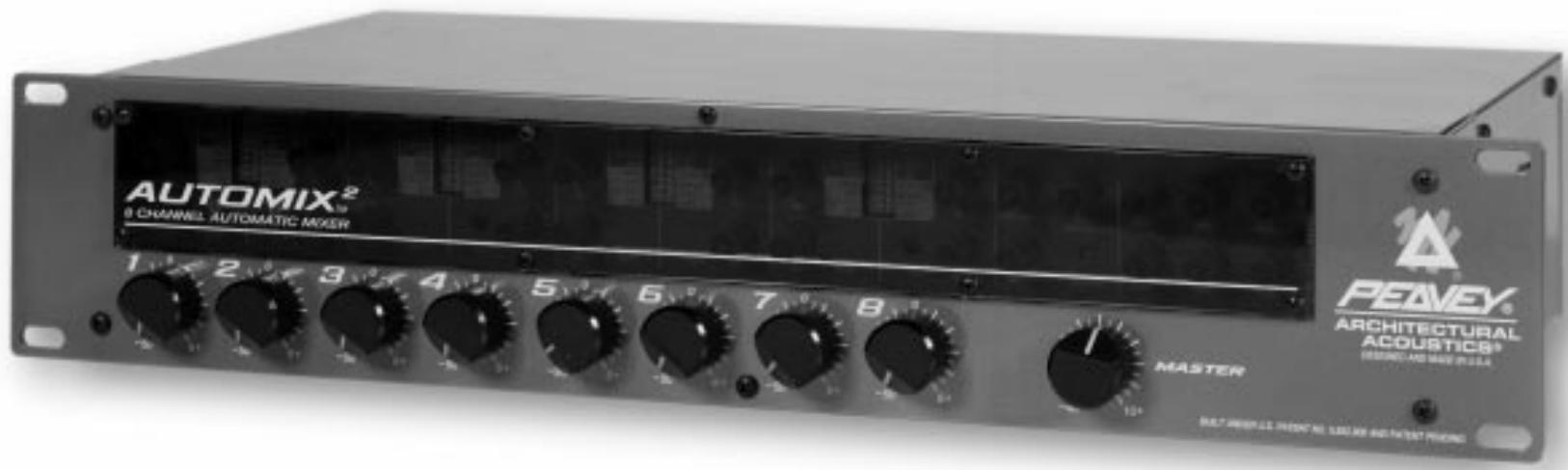
Thank you for purchasing the Automix™ 2! The Architectural Acoustics Automix™ 2 is a high quality automatic mixer with eight transformer balanced mic/line inputs. Each channel provides a gain control, 48 Volt phantom power (mic inputs), low cut filter, activity/clipping LED, an Aux send control and a choice between manual or automatic operation. Each channel also provides a defeatable insert point, 5 Volt TTL status output and can be muted individually or multiple channels can be muted simultaneously via an assignable mutebus. In addition, channels one and two provide an adjustable priority control.
The master section provides a gain trim control, three 1/9 octave sweepable notch filters, a downward expander, transformer balanced outputs (main and aux) and remote volume connections. The Automix™ 2 has been designed to easily link multiple units together to form a single mixer with many more inputs (16, 24, 32...). The Automix 2 is supplied with a see-through plexiglass security panel to prevent changes to the installer's settings.
Manual Mode: In the manual mode the channel level controls provide 6dB of gain and 50dB of attenuation.
Auto Mode: In the auto mode the control still provides 50dB of attenuation, but the control does not add gain to the overall system level. Instead, when the level is adjusted above "0", the other channels are attenuated to make the channel being adjusted sound louder in the mix without adding to the system gain.
2. MASTER LEVEL
The master level controls the overall output level. The range is set for 10dB of gain above, and 40dB of attenuation.
INTERNAL PANEL
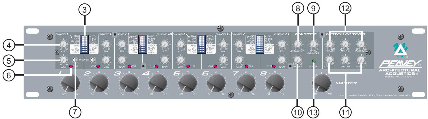
INTERNAL PANEL FEATURES
3. DIP SWITCHES
Each channel has four DIP switches that control the following functions.
A. MAN/AUTO
This switch determines whether the channel is operating in the automatic or manual mode.
B. OFF/MBUS
This switch is used to connect the channel to the system mutebus. This allows multiple inputs to be muted simultaneously under external control. See MUTEBUS, page 7.
C. LO CUT/FLAT
This switch selects the low cut filter. The low cut filter provides a low frequency rolloff that will help minimize unwanted noise (handling of mics, bumping of table, etc...). The rolloff starts at 100Hz (-3dB) and is a 6dB per octave filter.
D. OFF/+48
When this switch is in the +48 position, +48 volts of phantom power is supplied to the mic ± terminals. This provides power for condenser mics and should be defeated when using dynamic microphones or unbalanced inputs.
4. AUX SEND CONTROL
Controls the level of the signal being sent to the AUX bus. The level being sent to the Aux bus will also be affected if the gain control in that channel is changed.
5. GAIN TRIM
This control sets the input gain in each channel. The amount of gain is adjustable from +25dB to +60dB. (Mic input.)
6. ACTIVITY/CLIPPING LED ACTIVITY
In the automatic mode the LED will glow green, indicating the channel that is predominant in the mix (auto mode). If the channel is in the manual mode the LED will stay on if the front panel level control is at or above the 12:00 position. The green LED is also an indication of the status output state. If the LED is on, then the status output will be high (+5 Volts). If the LED is off, then the status output will be low (0 Volts).
CLIPPING
The LED will turn red if the channel is within 1dB of clipping.
7. PRIORITY (CHANNEL 1 and 2 ONLY)
Turning the priority control clockwise allows one channel to override the others in the mix. It does this by "tricking" the gain computing circuits into thinking this channel is louder than the others. Up to 9dB of priority is available.
8. AUX MASTER LEVEL CONTROL
This control sets the level of the signal being sent to the Aux Out. This level should be set after the individual channel levels have been set.
9. DOWNWARD EXPANDER
The downward expander can be used to attenuate the system gain when all of the input signals are low. This can be used to prevent background room noise from being amplified.
SETTING THE DOWNWARD EXPANDER
Have someone speak into a microphone at the softest level you can expect to encounter. Slowly turn the downward expander clockwise until the background noise between words is attenuated. Be careful not to go too far. The more downward expander that is used, the less "natural" sounding the system will become.
This method will give you a good starting point, but the best way to set the downward expander is during an actual meeting or event. While doing this, the downward expander can be adjusted for the best sound. If you have to deal with both loud and quiet events, you will need to trade off between natural sounding ambient and background noise.
10. MASTER GAIN TRIM
This control sets the maximum overall system gain and should be set with the front panel master gain set to the full clockwise position, all channels at unity, and external power amps turned up and locked at operational settings. When trimmed to a safe margin below feedback, no combination of user controls can cause feedback. This trim provides up to 25dB of attenuation of the system gain.
11. NOTCH FILTER LEVEL CONTROL
The notch filter level control adjusts the amount of cut at the frequency selected by the corresponding frequency control (12). It is adjustable from 0dB to 15dB of cut.
12. NOTCH FILTER FREQUENCY CONTROL
The notch filter frequency control is used to select the center frequency of the notch filter. The bottom filter has a range of 40Hz to 925Hz . The middle filter has a range of 260Hz to 6kHz . The upper filter has a range of 500Hz to 12kHz .
13. POWER LED
Indicates that AC mains power power is connected and power switch is in the "ON" position.
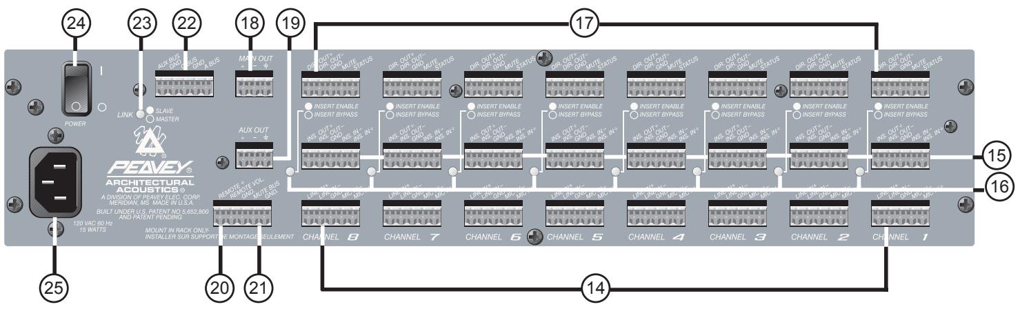
BACK PANEL FEATURES
14. MIC INPUTS
For use with low impedance microphones or low level sources. This is a transformer balanced input with an impedance of 2,000Ω . Input sensitivity for nominal output is -56dBu to -19dBu.
LINE INPUTS
These allow line level inputs to be used. This is a transformer balanced input through a 30dB resistive pad. Input impedance is >20kΩ
15. INSERT IN/OUT
This is a signal loop that allows an external device such as an EQ to be inserted into the signal path of individual channels (refer to diagram below).
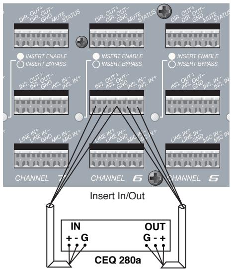
16. INSERT BYPASS SWITCH
When no signal processor is being used or bypassing the signal processor is desired, this switch should be in the "in" position. If a signal processor is being used, then this switch should be in the "out" position.
17. DIRECT OUTPUTS
Each channel has direct output terminals that can be used for recording or anytime the output of an individual channel is required. This signal is independent of "Automix" gain manipulation. The nominal output level is 2.21dBu (1 Volt).
MUTE
Channels can be muted individually by shorting this terminal to ground. It provides approximately 45dB of attenuation.
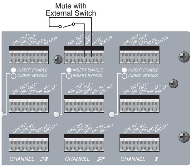
STATUS OUTPUT
The status output is a DC logic output that is high (+5 Volts) when the channel is active and low (0Volts) when the channel is not active. This DC voltage can be used to key video cameras or trigger key lights on active microphones.
NOTE: Each channel can source a maximum of 10 mA.
18. MAIN OUT
The main output is a 600Ω , transformer balanced output that can be used to feed an external power amplifier. It is at this point the automatically mixed or the manually mixed output is accessed. The nominal output is 2.21 dBu (1 volt).
19. AUX OUT
The aux output is a 600Ω , transformer balanced output that can be used as an additional non-automixed output. The nominal output is 2.21 dBu (1 volt).
20. REMOTE VOLUME
The master level of the mixer can be controlled remotely with a simple connection on the back of the unit. A 10k pot will provide approximately 0 to 25dB of attenuation. A 100k pot will provide 0 to 45dB of attenuation. If desired, a control voltage can be inserted to command 0 to 70dB of attenuation. The internal gain trim must be set full clockwise to achieve the maximum attenuation range of the remote volume (refer to diagram below).

NOTE: THE CONTROL VOLTAGE SHOULD NEVER EXCEED 13 VOLTS DC.
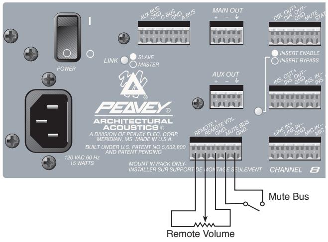
21. MUTEBUS
The mutebus is a control port that when shorted to ground will mute all channels that are assigned to the mutebus approximately 45dB. The channels to be muted must be assigned to the mutebus using the internal switch marked OFF/MBUS. See INTERNAL PANEL FEATURES, page 4 and diagram page 7.
22. LINK PORT
To increase the number of inputs available, multiple Automixers can be linked together. Linking automixers is a very simple process. It can be done with a small flat-head screwdriver and a short length of four conductor shielded wire. The following diagram and procedures will ensure proper linking.
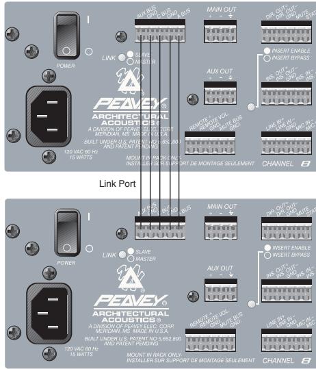
- Make a linking cable.
- Connect the mixers according to the diagram above.
- Select the mixer to be used as the master and place its link switch in the "master" position.
- All other mixers in the system should have their link switches in the "slave" position.
You now have a 16 (or more) channel automatic mixer. The master controls of the unit chosen as "master" should be used to control the system.
23. LINK SWITCH
The link switch is used to place the unit in the master or slave mode of operation. A standalone unit should always be in the master mode. See Link Port (#22).
24. POWER SWITCH
Switch to "I" position to turn on.
25. IEC INLET (AC)

With the Power Switch in the off (O) position, plug the power cord into this connector prior to plugging into your AC power source. Always ensure proper AC voltage and grounding practices are utilized (proper voltage is labeled under inlet).
NOTE: FOR UK ONLY
As the colors of the wires in the mains lead of this apparatus may not correspond with the colored markings identifying the terminals in your plug, proceed as follows: (1) The wire which is colored green and yellow must be connected to the terminal which is marked by the letter E or by the earth symbol or colored green or green and yellow. (2) The wire which is colored blue must be connected to the terminal which is marked with the letter N or the color black. (3) The wire which is colored brown must be connected to the terminal which is marked with the letter L or color red.
AUTOMIX™ 2 SPECIFICATIONS
Nominal Out = 2.21 dBu = 1 Volt
Input Specifications:
| Function | Input z (ohms) Min | Input Gains Setting | Input Levels (to bal. outputs) | Bal./ Unbal. | Connector | ||
| Min* | Nominal** | Max | |||||
| Microphone (150 ohms) | 2k | Max Gain (60dB) | -64dBu (0.5mV) | -43dBu (5.5mV) | -2dBu (615mV) | Bal. | Mic In (+) Mic In (-) Ground |
| Line (10K ohms) | >20k | Max Gain (30dB) | -35dBu 13.7mV | -14dBu (155mV) | +27dBu (17.4V) | Bal. | Line In (+) Line In (-) Ground |
- Minimum input level (Sensitivity) is the smallest signal that will produce nominal output (2.21dBu) with channel and master controls set for maximum gain.
** Nominal settings are defined s all control set at 0 dB (or 50% rotation for rotary pots.
EIN: -122dBu (Max gain, terminated 150 Ohms)
Phantom Power: +48 Volts at Mic ± terminated
Priority (Channels 1 and 2): 0dB to 9dB
Low Cut Filter: -3dB at 100Hz (6dB per octave)
Common Mode: >65dB at 20Hz — 20kHz
Rejection Ratio: >85dB @ 1kHz
Output Specifications:
| Function | Minimum Load Z (Ohms) | Output Levels | Bal./ Unbal. | Connector Main Out (=) | ||
| Nominal | Max | |||||
| Main Out | 600 | +2.21dBu (1V) | +20dBu (7.75V) (Hi Z load) | +16dBm (6.44V) (600Ω load) | Bal. | Main Out (+) Main Out (-) Ground |
| Aux Out | 600 | +2.21dBu (1V) | +20dBu (Hi Z load) | +16dBm (600Ω load) | Bal. | Aux Out (+) Aux Out (-) Ground |
Distortion:
Mic Input to Main Output: <0.2% at nominal (20Hz to 20kHz)
Frequency Response:
Mic Input Main Output: 20Hz to 20kHz +0/-1 dB at nominal
Mic Input to Aux Output: 20Hz to 20kHz +0/-1 dB at nominal
AUTOMIX™ 2 SPECIFICATIONS
Hum and Noise:
| Output | Residual Noise Ref: 0 dBu | S/N Ratio Ref: 2:21 dBu | Test Conditions |
| Main Out | -85dBu | 87dB | All controls down |
| -84dBu | 86dB | One channel nominal, Master level nominal | |
| Aux Out | -85dBu | 87dB | All controls down |
| -80dBu | 82dB | One channel send nominal, Monitor master nominal | |
(Hum and noise measurements: 22Hz to 22kHz BW)
GENERAL SPECS:
| Remote volume range: | 0dB to 70dB of attenuation |
| Off channel attenuation: | 0dB to 70dB |
| Mute: | Channel is attenuated 45dB when Mute to ground connection is made. |
| MuteBus: | Multiple channels can be attenuation 45dB when MuteBus to ground connection is made. |
| Status output: | Status is high (5V) when channel is active. It is low (0V) when channel is not active. |
| Power consumption: | AC 120 Volts, 60Hz, Domestic AC 230 Volts, 50/60 Hz Export 15 watts |
| Weight: | 11 pounds |
| Dimensions: | Width: 19 inches Depth: 9 1/4 inches Height: 3 1/2 inches |
AUTOMIX™ 2
Setting up the Automix™ 2
1. Wiring Inputs and Outputs:
For best results, it is recommended that two-conductor shielded cable is used for all input and output connections. When making connections remember to observe proper polarity. The recommended strip length for the detachable screw terminals is 1/2" .
2. Initial Control Settings:
| Channel Levels | (Faceplate) | — | Full CCW |
| Channel Gain Trims | /Internal) | — | Full CCW |
| Aux Send Controls | /Internal) | — | Full CCW |
| Priority | /Internal) | — | Full CCW |
| Notch Controls | /Internal) | — | Full CCW |
| Downward Expander | /Internal) | — | Full CCW |
| Aux Master Level | /Internal) | — | Full CCW |
| Master Level | (Faceplate) | — | Full CW |
| Master Gain Trim | /Internal) | — | Full CCW |
All channels in the "auto" mode
3. Setting the Channel Level:
Set the front panel control (of the channel that is being adjusted) to the middle (12 o'clock) position. Connect a mic or line input to the first channel. While someone is speaking into the mic (in a way that it would normally be used), slowly increase the channel gain trim until a slight ringing (feedback) is heard or until the clip led begins to blink red occasionally. Turn the channel gain trim down slowly until the ringing is no longer audible. This is the maximum level that the gain trim should be set. Turn the external channel level control down (full CCW).
NOTE: The internal master gain trim (#10) may need to be turned up (CW) if the channels can be easily driven into clipping, or feedback cannot be obtained in the normal operating range of the internal gain trim control.
Repeat this step for the remaining channels.
Return all of the external channel levels controls to their mid position (12 o'clock).
4. Setting the Notch Filter:
The notch filter can be set in a couple of ways. It can be set using test equipment to pinpoint frequencies that are prone to feedback, or it can be set "by ear." For the purpose of this manual, the "by ear" method will be described:
A. Slowly increase the master gain trim (internal) until a slight ringing is audible.
B. Select the proper frequency range and turn the corresponding level control CW to about the 12 o'clock position.
C. Slowly turn the frequency control back and forth until the ringing is no longer audible.
D. Again, slowly increase the master gain trim until ringing is heard. If this is a different frequency, repeat steps B and C. If it is not a different frequency, try turning the frequency control while listening to the feedback. Stop when the feedback is as low as possible. If the feedback is still audible, turn the corresponding level control CW toward the -15 setting until the feedback is gone.
5. Setting the Overall Level:
Set the master level control (external) for the desired overall output level. This mixer's levels are now set and the mixer's other features (downward expander, low cut and priorities) can be set as desired for the application.
6. Attaching the Security Panel:
Attach the security plexiglass with the eight supplied screws. This will prevent any unwanted tampering with the settings.
INTRODUCCION
Effective Date: July 1, 1998
What This Warranty Covers
Your Peavey Warranty covers defects in material and workmanship in Peavey products purchased and serviced in the U.S.A. and Canada.
What This Warranty Does Not Cover
The Warranty does not cover: (1) damage caused by accident, misuse, abuse, improper installation or operation, rental, product modification or neglect; (2) damage occurring during shipment; (3) damage caused by repair or service performed by persons not authorized by Peavey; (4) products on which the serial number has been altered, defaced or removed; (5) products not purchased from an Authorized Peavey Dealer.
Who This Warranty Protects
This Warranty protects only the original retail purchaser of the product.
How Long This Warranty Lasts
The Warranty begins on the date of purchase by the original retail purchaser. The duration of the Warranty is as follows:
| Product Category | Duration |
| Guitars/Basses, Amplifiers, Pre-Amplifiers, Mixers, Electronic Crossovers and Equalizers | 2 years * (+ 3 years) |
| Drums | 2 years * (+ 1 year) |
| Enclosures | 3 years * (+ 2 years) |
| Digital Effect Devices and Keyboard and MIDI Controllers | 1 year * (+ 1 year) |
| Microphones | 2 years |
| Speaker Components (incl. speakers, baskets, drivers, diaphragm replacement kits and passive crossovers) and all Accessories | 1 year |
| Tubes and Meters | 90 days |
[denotes additional warranty period applicable if optional Warranty Registration Card is completed and returned to Peavey by original retail purchaser within 90 days of purchase.]
What Peavey Will Do
We will repair or replace (at Peavey's discretion) products covered by warranty at no charge for labor or materials. If the product or component must be shipped to Peavey for warranty service, the consumer must pay initial shipping charges. If the repairs are covered by warranty, Peavey will pay the return shipping charges.
How To Get Warranty Service
(1) Take the defective item and your sales receipt or other proof of date of purchase to your Authorized Peavey Dealer or Authorized Peavey Service Center.
OR
(2) Ship the defective item, prepaid, to Peavey Electronics Corporation, International Service Center, 412 Highway 11 & 80 East, Meridian, MS 39301 or Peavey Canada Ltd., 95 Shields Court, Markham, Ontario, Canada L3R 9T5. Include a detailed description of the problem, together with a copy of your sales receipt or other proof of date of purchase as evidence of warranty coverage. Also provide a complete return address.
Limitation of Implied Warranties
ANY IMPLIED WARRANTY, INCLUDING WARRANTYES OF MERCHANTABILITY AND FITNESS FOR A PARTICULAR PURPOSE, ARE LIMITED IN DURATION TO THE LENGTH OF THIS WARRANTY.
Some states do not allow limitations on how long an implied warranty lasts, so the above limitation may not apply to you.
Exclusions of Damages
PEAVEY'S LIABILITY FOR ANY DEFECTIVE PRODUCT IS LIMITED TO THE REPAIR OR REPLACEMENT OF THE PRODUCT, AT PEAVEY'S OPTION. IF WE ELECT TO REPLACE THE PRODUCT, THE REPLACEMENT MAY BE A RECONDITIONED UNIT. PEAVEY SHALL NOT BE LIABLE FOR DAMAGES BASED ON INCONVENIENCE, LOSS OF USE, LOST PROFITS, LOST SAVINGS, DAMAGE TO ANY OTHER EQUIPMENT OR OTHER ITEMS AT THE SITE OF USE, OR ANY OTHER DAMAGES WHETHER INCIDENTAL, CONSEQUENTIAL OR OTHERWISE, EVEN IF PEAVEY HAS BEEN ADVISED OF THE POSSIBILITY OF SUCH DAMAGES
Some states do not allow the exclusion or limitation of incidental or consequential damages, so the above limitation or exclusion may not apply to you.
This Warranty gives you specific legal rights, and you may also have other rights which vary from state to state.
If you have any questions about this warranty or service received or if you need assistance in locating an Authorized Service Center, please contact the Peavey International Service Center at (601) 483-5365 / Peavey Canada Ltd. at (905) 475-2578.
Features and specifications subject to change without notice.
IMPORTANT SAFETY INSTRUCTIONS
WARNING: When using electric products, basic cautions should always be followed, including the following:
- Read these instructions.
- Keep these instructions.
- Heed all warnings.
- Follow all instructions.
- Do not use this apparatus near water. For example, near or in a bathtub, swimming pool, sink, wet basement, etc.
- Clean only with a damp cloth.
- Do not block any of the ventilation openings. Install in accordance with manufacturer's instructions. It should not be placed flat against a wall or placed in a built-in enclosure that will impede the flow of cooling air.
- Do not install near any heat sources such as radiators, heat registers, stoves or other apparatus (including amplifiers) that produce heat.
- Do not defeat the safety purpose of the polarized or grounding-type plug. A polarized plug has two blades with one wider than the other. A grounding type plug has two blades and a third grounding plug. The wide blade or third prong is provided for your safety. When the provided plug does not fit into your inlet, consult an electrician for replacement of the obsolete outlet. Never break off the grounding write for our free booklet "Shock Hazard and Grounding". Connect only to a power supply of the type marked on the unit adjacent to the power supply cord.
- Protect the power cord from being walked on or pinched particularly at plugs, convenience receptacles, and the point they exit from the apparatus.
- Only use attachments/accessories provided by the manufacturer.
- Use only with a cart, stand, tripod, bracket, or table specified by the manufacturer, or sold with the apparatus. When a cart is used, use caution when moving the cart/apparatus combination to avoid injury from tip-over.
- Unplug this apparatus during lightning storms or when unused for long periods of time.
- Refer all servicing to qualified service personnel. Servicing is required when the apparatus has been damaged in any way, such as power-supply cord or plug is damaged, liquid has been spilled or objects have fallen into the apparatus, the apparatus has been exposed to rain or moisture, does not operate normally, or has been dropped..
- If this product is to be mounted in an equipment rack, rear support should be provided.
- Exposure to extremely high noise levels may cause a permanent hearing loss. Individuals vary considerably in susceptibility to noise induced hearing loss, but nearly everyone will lose some hearing if exposed to sufficiently intense noise for a sufficient time. The U.S. Government's Occupational and Health Administration (OSHA) has specified the following permissible noise level exposures:
Duration Per Day In Hours
8
6
4
3
2
1 1/2
1
1/2
1/4 or less
Sound Level dBA, Slow Response
90
92
95
97
100
102
105
110
115
According to OSHA, any exposure in excess of the above permissible limits could result in some hearing loss. Ear plugs or protectors to the ear canals or over the ears must be worn when operating this amplification system in order to prevent a permanent hearing loss if exposure is in excess of the limits as set forth above. To ensure against potentially dangerous exposure to high sound pressure levels, it is recommended that all persons exposed to equipment capable of producing high sound pressure levels such as this amplification system be protected by hearing protectors while this unit is in operation.
SAVE THESE INSTRUCTIONS!

PEAVEX
ARCHITECTURAL ACOUSTICS
Features and specifications subject to change without notice.
Peavey Electronics Corporation • 711 A Street • Meridian • MS • 39301
(601) 483-5376 • FAX (601) 486-1678 • www.peavey.com

80304515
- MASTER LEVEL
- INTERNAL PANEL
- INTERNAL PANEL FEATURES
- DIP SWITCHES
- AUX SEND CONTROL
- GAIN TRIM
- ACTIVITY/CLIPPING LED ACTIVITY
- CLIPPING
- PRIORITY (CHANNEL 1 and 2 ONLY)
- AUX MASTER LEVEL CONTROL
- DOWNWARD EXPANDER
- SETTING THE DOWNWARD EXPANDER
- MASTER GAIN TRIM
- NOTCH FILTER LEVEL CONTROL
- NOTCH FILTER FREQUENCY CONTROL
- POWER LED
- BACK PANEL FEATURES
- MIC INPUTS
- LINE INPUTS
- INSERT IN/OUT
- INSERT BYPASS SWITCH
- DIRECT OUTPUTS
- MUTE
- STATUS OUTPUT
- MAIN OUT
- AUX OUT
- REMOTE VOLUME
- MUTEBUS
- LINK PORT
- LINK SWITCH
- POWER SWITCH
- IEC INLET (AC)
- NOTE: FOR UK ONLY
- AUTOMIX™ 2 SPECIFICATIONS
- Distortion:
- Frequency Response:
- AUTOMIX™ 2
- Setting up the Automix™ 2
- Wiring Inputs and Outputs:
- Initial Control Settings:
- Setting the Channel Level:
- Setting the Notch Filter:
- Setting the Overall Level:
- Attaching the Security Panel:
- INTRODUCCION
- What This Warranty Covers
- What This Warranty Does Not Cover
- Who This Warranty Protects
- How Long This Warranty Lasts
- What Peavey Will Do
- How To Get Warranty Service
- OR
- Limitation of Implied Warranties
- Exclusions of Damages
- IMPORTANT SAFETY INSTRUCTIONS
- SAVE THESE INSTRUCTIONS!
Brand : PEAVEY
Model : AUTOMIX 2
Category : Audio Mixer