
GPS - Amplifier PEAVEY - Free user manual and instructions
Find the device manual for free GPS PEAVEY in PDF.

| Product Type | Power Amplifier |
| Brand | PEAVEY |
| Model | GPS Series (900, 1500, 2600, 3400, 3500) |
| Number of Channels | 2 (stereo) or 1 (bridged) |
| Output Power (e.g. GPS 3500) | 1750 W RMS per channel into 2 ohms (stereo), 1200 W RMS per channel into 4 ohms (stereo), 775 W RMS per channel into 8 ohms (stereo), 3400 W RMS into 4 ohms (bridged) |
| Minimum Load Impedance | 2 ohms per channel (stereo), 4 ohms (bridged) |
| Frequency Response | 10 Hz – 100 kHz (+0/-3 dB at 1 W) |
| Input Sensitivity | 1.4 V RMS (for rated power into 2 ohms, gain x40) |
| Voltage Gain | 32 dB (x40) |
| Power Supply | 120 V AC (domestic version), detachable IEC power cord |
| Power Consumption (1/8 power into 2 ohms) | 1400 W (GPS 3500) |
| Cooling | Two 80 mm DC fans with variable speed based on temperature |
| Built-in Protections | Thermal, short circuit, DC voltage, subsonic, initialization protection (IP™), Load Fault Correction (LFC™), DDT™ (anti-clip compression) |
| Input Connectors | Neutrik® Combo (XLR + 6.35 mm jack) per channel, THRU output |
| Output Connectors | Speakon® (for 2600/3400/3500 models) or 6.35 mm jack (for 900/1500) + 5-way binding posts |
| Dimensions (W x H x D) | 483 x 133 x 432 mm (19 x 5.23 x 17 inches) |
| Weight (e.g. GPS 3500) | 23.3 kg (51.3 lb) |
| Rack Mounting | 2 units (2U), standard 48 cm rack |
| LED Indicators | Power, Signal, DDT/Clip |
| Maintenance | Clean with a dry cloth; do not obstruct ventilation grilles; refer all repairs to authorized service technician |
Frequently Asked Questions - GPS PEAVEY
User questions about GPS PEAVEY
0 question about this device. Answer the ones you know or ask your own.
Ask a new question about this device
Download the instructions for your Amplifier in PDF format for free! Find your manual GPS - PEAVEY and take your electronic device back in hand. On this page are published all the documents necessary for the use of your device. GPS by PEAVEY.
USER MANUAL GPS PEAVEY
GPS™ Series Amplifiers

Intended to alert the user to the presence of uninsulated "dangerous voltage" within the product's enclosure that may be of sufficient magnitude to constitute a risk of electric shock to persons.

Intended to alert the user of the presence of important operating and maintenance (servicing) instructions in the literature accompanying the product.
CAUTION: Risk of electrical shock — DO NOT OPEN!
CAUTION: To reduce the risk of electric shock, do not remove cover. No user serviceable parts inside. Refer servicing to qualified service personnel.
WARNING: To prevent electrical shock or fire hazard, do not expose this appliance to rain or moisture. Before using this appliance, read the operating guide for further warnings.

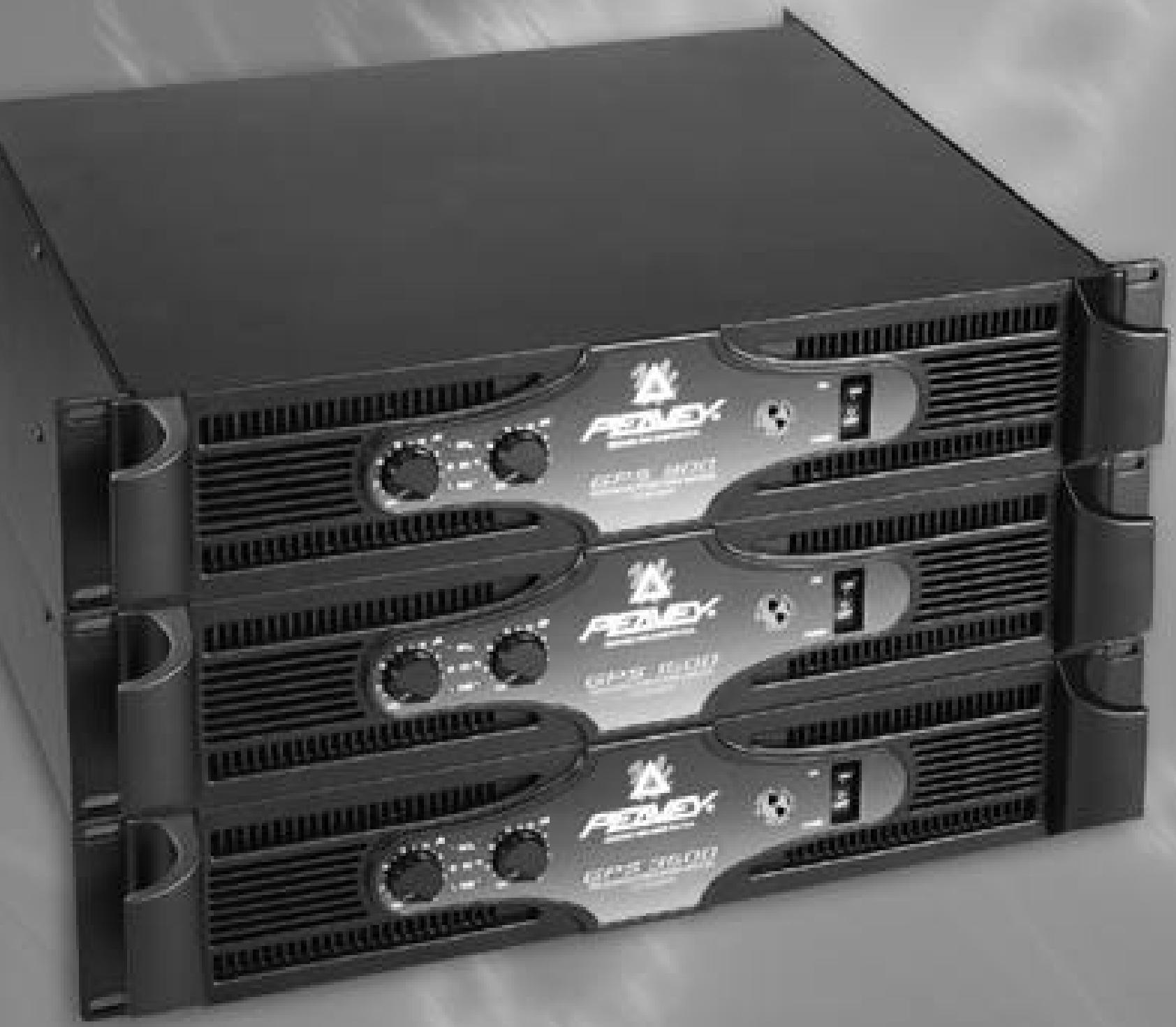
Congratulations on your purchase of the new GPS Series amplifier by Peavey Electronics. Years of power amp design and testing have produced a totally refined, dynamic power amp product line. The GPS Series consists of the GPS 900, GPS 1500, GPS 2600, GPS 3400 and GPS 3500. Each model features tunnel cooling, two variable-speed fans, initialization protection and DDT TM speaker protection. There are, however, differences between the various models such as output power and connections. This guide will describe each feature of your GPS Series amplifier and note the features common to specific models. The chart below offers a quick reference.
| GPS™ Series Power Amps | ||||
| SPECIFICATIONS | GPS™ 900 | GPS™ 1500 | GPS™ 2600 | GPS™ 3500 |
| OUTPUT POWER | ||||
| Stereo mode, both channels driven | ||||
| 2 ohms, 1 kHz, 0.1% THD | 450W RMS per channel | 750W RMS per channel | 1300W RMS per channel | 1700W RMS per channel |
| 4 ohms, 1 kHz, 0.1% THD | 330W RMS per channel | 550W RMS per channel | 950W RMS per channel | 1200W RMS per channel |
| 8 ohms, 1 kHz, 0.1% THD | 200W RMS per channel | 320W RMS per channel | 620W RMS per channel | 775W RMS per channel |
| Bridge mode, mono | ||||
| 4 ohms, 1 kHz, 0.1% THD | 900W RMS | 1500W RMS | 2600W RMS | 3500W RMS |
| 8 ohms 1 kHz, 0.1% THD | 660W RMS | 1100W RMS | 1900W RMS | 2400W RMS |
| RATED OUTPUT POWER: | ||||
| Stereo mode, both channels driven | ||||
| 4 ohms, 20 Hz to 20 kHz, 0.03% THD | 300W RMS per channel | 500W RMS per channel | 900W RMS per channel | 1050W RMS per channel |
| 8 ohms, 20 Hz to 20 kHz, 0.02% THD | 1700W RMS per channel | 280W RMS per channel | 600W RMS per channel | 750W RMS per channel |
| 4 ohms, 20 Hz to 20 kHz, 0.1% THD | ||||
| 8 ohms, 20 Hz to 20 kHz, 0.08% THD | ||||
| SLEW RATE:(Typical value) | ||||
| Stereo mode, each channel | 40 Volts per μsec | 40 Volts per μsec | 40 Volts per μsec | 40 Volts per μsec |
| Bridge mode, mono | 80 Volts per μsec | 80 Volts per μsec | 80 Volts per μsec | 80 Volts per μsec |
| INPUT SENSITIVITY & IMPEDANCE: | ||||
| @ rated output power, 4 ohms | 0.87V RMS | 1.12V RMS | 1.54V RMS | 1.62V RMS |
| unbalanced, 1/4" phone jack | 20 k ohms | 20 k ohms | 20 k ohms | 20 k ohms |
| Balanced, XLR (polarity selectable) | 10 k ohms per leg | 10 k ohms per leg | 10 k ohms per leg | 10 k ohms per leg |
| Overall system gain per channel | 40X (+32 dB) | 40X (+32 dB) | 40X (-32 dB) | 40X (+32 dB) |
| FREQUENCY RESPONSE: | ||||
| Stereo mode, both channels driven | ||||
| +0m -1 dB @ 1 WRMS, 4 ohms | 5 Hz to 50 kHz | 5 Hz to 50 kHz | 5 Hz to 100 kHz | 5 Hz to 100 kHz |
| +0, -0.2 dB @ rated output, 4 ohms | 20 Hz to 20 kHz | 20 Hz to 20 kHz | 10 Hz to 30 kHz | 10 Hz to 30 kHz |
| DAMPING FACTOR: (Typical value) | ||||
| Stereo mode, both channels driven | Greater than 400 | Greater than 400 | Greater than 700 | Greater than 325 |
| 8 ohms | ||||
| Hum & Noise: | ||||
| Stereo mode, both channels driven | ||||
| Below rated output power, 4 ohms | 100 dB, unweighted | 100 dB, unweighted | 100 dB, unweighted | 100 dB, unweighted |
Specifications subject to change without notice.
Please read this guide in its entirety. Pay close attention to the various warnings within as they pertain to the safety of you and your product. Each section will begin with a short description of the information you can expect to obtain within. This should help you to locate the material you are looking for in a timely manner. Once again, congratulations and thank you for buying Peavey!
UNPACKING/REGISTRATION
Inspect the amplifier during unpacking. If you find any damage, notify your dealer immediately. Be sure to save the carton and all packing materials. Should you ever need to ship the unit back to Peavey Electronics, one of its service centers, or the dealer, use only the original factory packing. Please fill out your registration card at this time. It is important that you complete the entire form and mail it to Peavey Electronics in order for your warranty to apply.
INSTALLATION AND MOUNTING
GPS Series amplifiers are 2-rack-space units that mount in a standard 19-inch rack. On all amplifiers, four front panel mounting holes are provided. Refer to the specifications for your specific model in this manual.
QUICK START
The following section lists the steps for basic usage. This is only a quick reference. It is very important that you read the entire manual in order to ensure the safe and optimum operation of your GPS Series amplifier.
TO SET UP THE AMPLIFIER FOR BASIC USAGE:
- Rack mount the amplifier in the location where it is to be used, remembering to allow for adequate access and cooling space. For more information, see the section on Cooling Requirements.
- Make input connections, balanced or unbalanced, to the combination input connector on the rear panel. See the sections on The INs and OUTs of MODE SELECTION for more information.
- Connect speakers to the output jacks or binding posts. Be sure to make the correct output connections for stereo or bridged mono configuration. See the section on The INs and OUTs of MODE SELECTION for more information.
- Make power connections, allowing for proper current draw. See the section on AC Mains Circuit Size Requirements for more information.
- Turn down (fully counterclockwise) the two gain attenuators on the front panel. Turn the front panel AC switch to "ON," and bring up the gain attenuators to the desired levels.
AC POWER
The following section will describe the AC power features of your GPS Series amplifier. AC power is a critical element in power amplification. Please read this section carefully, paying special attention to any warning signs. Refer to the diagram below and on page 8 to locate these features. Refer to page 7 for operation notes regarding AC power.
NOTE: Always make connections to your GPS Series amplifier while the unit is turned off.
1. REMOVABLE AC POWER CORD (Located on the rear of the unit)
This receptacle is for the IEC line cord (included), which provides AC power to the unit. Connect the line cord to this connector and to a properly grounded AC supply. Damage to the equipment may occur if an improper line voltage is used. (See voltage marking on unit.) Never remove or cut the ground pin
of the line cord plug. This unit is supplied with a properly rated line cord. When lost or damaged, replace this cord with one of the proper ratings.
2. AC POWER SWITCH (Located on the front of the unit. See diagram on page 9.)
A two-position power switch is on the right side of the front panel. With the top portion of the switch pushed to the "IN" position the amplifier is "ON". Press the bottom portion of the switch to the "IN" position to turn the unit "OFF".
3. POWER LED (Located on the front of the unit. See diagram on page 9.)
The Power LEDs illuminate to indicate the amplifier is turned on.
REAR PANEL
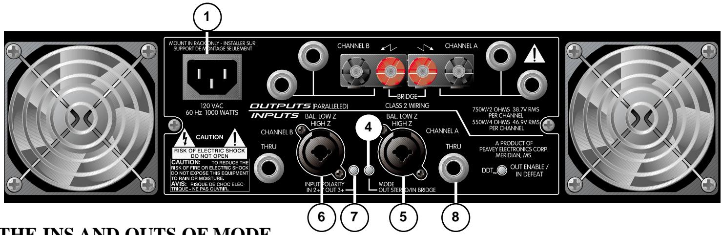
THE INS AND OUTS OF MODE SELECTION
Once you have provided proper AC power to the amplifier, you may now connect to the inputs and outputs. Remember to do this while the power to the unit is turned off (Power LED are not lit). The rear panel of your GPS Series amplifier provides a central location for all input and output connections. Regardless of the GPS model, all input connections are located at the bottom-center portion of the rear panel and all output connections are located at the top-center portion. In addition, your amplifier can operate in either stereo or bridged (mono) mode. All GPS Series amplifiers have DDT compression. However, only GPS models 900 and 1500 have a switch to defeat this feature. This section will describe these areas of your GPS Series amplifier in detail.
MODE SELECTION
4. MODE SWITCH
This switch determines which mode your amplifier will operate in. Before connecting your input signal and speaker cables to the amp, you must determine how you want the amp to function. Two modes of operation are offered on your amplifier, stereo or bridged (seperate).
STEREO:
When we use the term "stereo" we are referring to two channels, not necessarily left and right.
Therefore, in "stereo" mode there are essentially two power amps regardless of input type. You may use a stereo input, one stereo input to each channel of the GPS, or you may send two mono inputs to the GPS in the same manner. A good example of two separate inputs would be the use of one channel for mono mains and one channel for mono monitor signals. In order to select the "stereo" mode of operation you must place the Mode Switch in the "out" position. In this mode, Channel A Output is supplied by the Channel A Input. Channel B Output is supplied by Channel B Input.
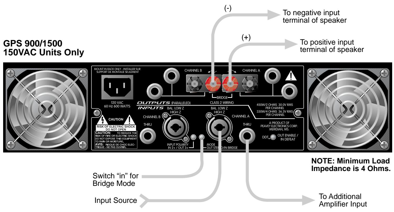
BRIDGED OR MONO:
In the "bridge" mode the two channels of the amplifier combine to form a single mono channel. The benefit of using your amplifier in this mode is that the power is doubled. Refer to the specifications in this manual for detailed output power specs on your specific model. To use the GPS Series amp in
"bridge" mode, place the Mode Switch to the "in" position where the switch remains down. The amp is now a mono amplifier and only requires a single input. Plug your input signal into Channel A only for "bridge" mode operation. Channel B input must not have anything connected.
NOTE FOR GPS 900 AND 1500:
When these models are switched to "bridge" mode, the Power LED (3) for Channel B will no longer illuminate.
NOTE: Refer to the Outputs section for an explanation of how the Mode Switch affects the speaker outputs.
INPUTS
5. CHANNEL A COMBINATION INPUT
GPS 900 AND 1500
These GPS Series amplifiers offer both XLR electronic balanced and phone jack quasi-balanced inputs for each channel using Neutrik®'s new "combo" connector to save panel space.
The female XLR inputs are connected to dual OP AMP circuitry which offers very low noise and extremely high common mode rejection ratio to minimize outside interference!

The female 1/4 phone jack input in the center of the "comb" connectors are also connected to a unique "quasi-balanced" input circuitry. When used, these 1/4 Jacks are not "chassis grounded" but connected to ground through a relatively low impedance circuit which is part of a "ground loop" elimination circuit associated with the input. This will normally allow "hum free" operation when relatively short 1/4 cable patches are made to this input by various outputs from other equipment that share the same rack with this amp. This "quasi-balanced" circuit is "automatic", and is virtually invisible in normal usage. It cannot be defeated. Use only a two-conductor (TS) phone plug when connecting to the 1/4 input of this connector.
GPS 2600, 3400 AND 3500
These GPS Series amplifiers offer both XLR electronic balanced and phone jack balanced/unbalanced inputs for each channel using Neutrik's new "comb" connector to save panel space.
The female 1/4 phone jack input in the center of the "comb" connectors is also connected to a unique balanced/unbalanced input circuitry. When used, these 1/4 jacks can accept both unbalanced two-conductor (TS) and balanced three-conductor (TRS) inputs. Balanced operation is always recommended for optimum signal-to-noise. If unbalanced operation is a required, always keep the input cable to a minimum length to avoid excessive noise.
6. CHANNEL B COMBINATION INPUT
This connector is identical to the Channel A Combination Input (5) except it is not used during "bridge" mode [See Mode Switch (4).]
7. INPUT POLARITY
Located between the Channel A and Channel B Inputs is a recessed Input Polarity switch (7) that allows the user to select the desired polarity (phase) of the XLR inputs. This switch is a push-push type and a small diameter "tool" is required to select the desired position. Set to the out (default) position, the polarity is pin #3 positive, pin #2 negative, and pin #1 ground. This is the polarity found on most Peavey power amplifiers. Although this is not the world "standard" (IEC) polarity, it was chosen by Peavey more than 20 years ago, and thus we offer this polarity to be consistent with products both past and present. If this amplifier is used with other competitive products which use the IEC standard polarity, then the "in" position of switch (7) should be selected yielding pin #2 positive, pin #3 negative, and pin #1 ground. As with any electronic gear, polarity (phasing) is important because the
loudspeaker enclosures associated with this power amplifier must be in phase with any other loudspeaker enclosures associated with other power amps. If one loudspeaker system were to "push" while the other "pulls", a serious sound "cancellation" could result. Changing the setting of the polarity switch has the same effect as reversing the polarity of the loudspeaker connections at the output.
8. THRU

Each channel has a female phone jack (8) labeled "thru". This Thru jack offers very flexible patching capability. When the XLR input of the combination connectors (5 and 6) are used, this THRU jack is the output of the electronic balanced input circuitry, and as such can be used as a "line out" to connect to the other input jack on this amplifier or other amps in the same rack. Thus, one balanced mixer feed can be connected to the amp via the XLR connector and then further distributed (unbalanced) locally via the THRU jack. Alternatively, when the 1/4 phone jack input of the combination connectors (5 and 6) is used as the input, the THRU jack becomes a "bridged" input to it (similar to a Y-cord), again allowing this input signal to be patched to the other input jack on this amplifier or other amps in the system. IMPORTANT: The THRU jack is not intended to be an "input", and inadvertent usage as such will result in excessive loading of the input source. Although not a catastrophic mistake, it will cause a significant reduction in "system gain" due to the loading, and will seriously limit the overall system performance.
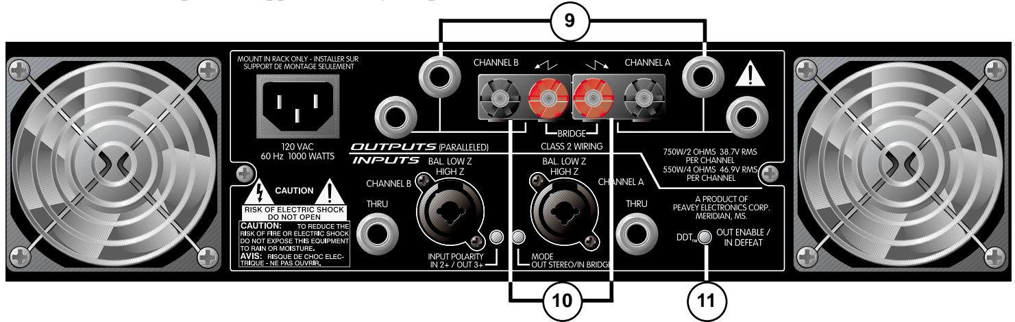
OUTPUTS
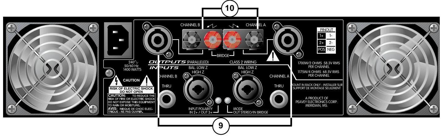
9. SPEAKER OUTPUT CONNECTORS
Each GPS Series amplifier offers two separate output sections featuring parallel outputs. The type of output jack differs from model to model. Find the model and AC supply voltage of your unit to identify which description is applicable to your product.
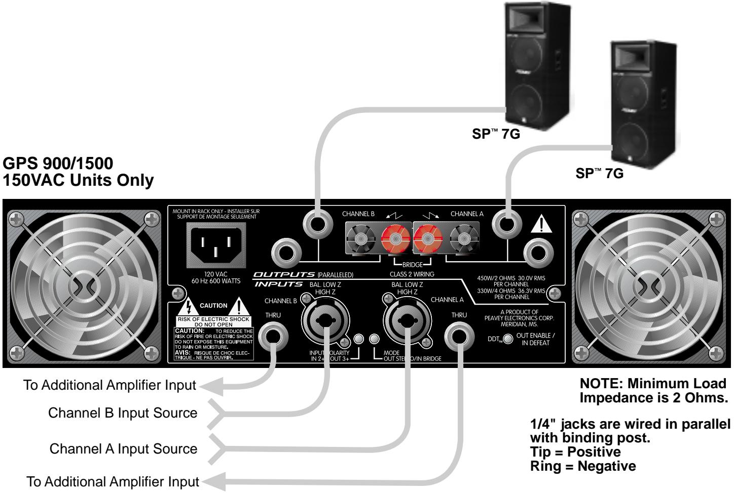
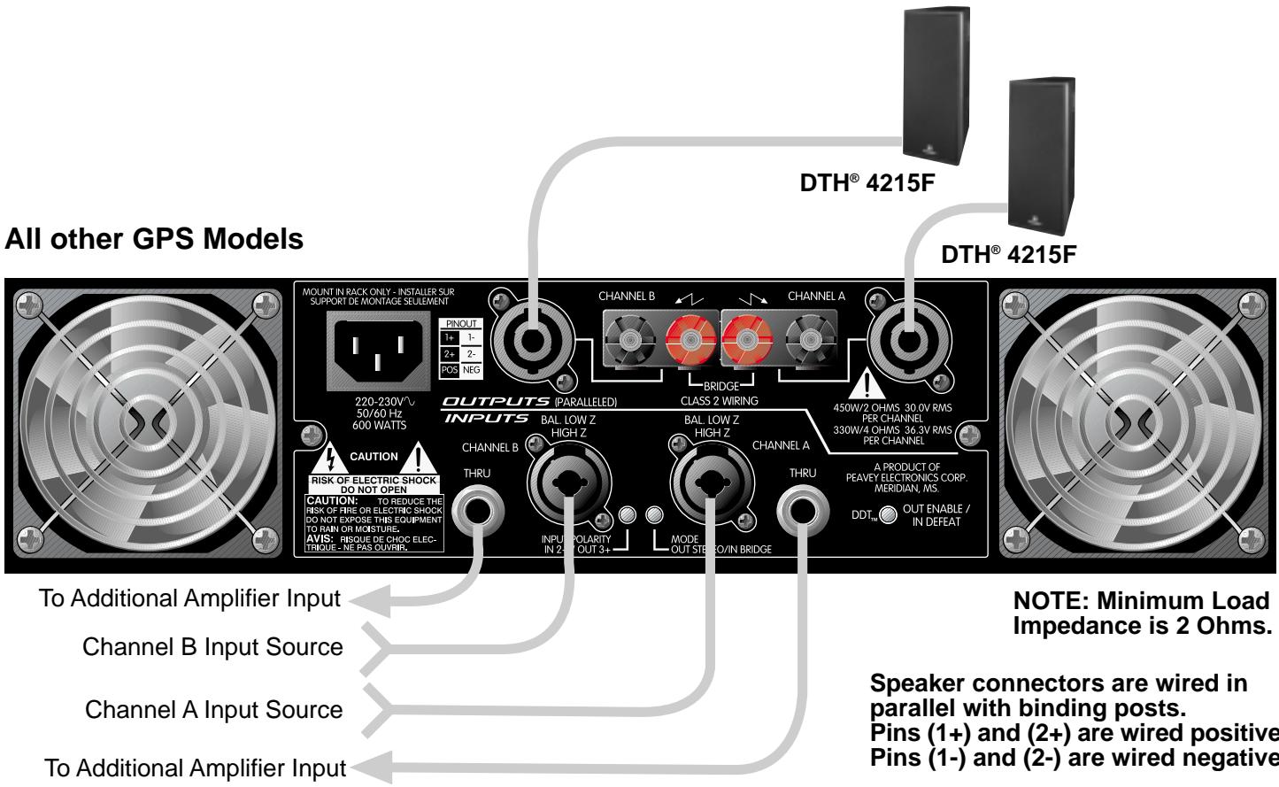
GPS 900 OR GPS 1500 120 VAC (DOMESTIC) MODELS:
These two models feature 1/4 output jacks located on the top-center of the rear panel. There are two parallel 1/4 jacks per channel which are labeled either "CHANNEL A" or "CHANNEL B". In addition to the 1/4 output jacks, Binding Posts (10) are also provided for each channel.
All other GPS models:
These models offer dual Speakon® Quick Connectors. The Speakon® is a four-wire connector with the connections labeled as 1+, 1-, 2+ and 2-. The Speakon connectors found on your GPS Series amplifier are connected with pins 1+ and 2+ wired in parallel to the positive output. Pins 1- and 2- are wired in parallel to the negative output. This is typical for each channel.
NOTE: Consult your loud speaker specifications to determine the wiring configuration that will best suit your system. The diagrams on pages 13 and 14 display the recommended hookup for your GPS Series amplifier. In addition to the Speakon® Quick Connectors, Binding Posts (10) are also provided for each channel.
10. BINDING POST OUTPUT CONNECTORS
Five-way binding post speaker outputs can be found on each channel regardless of model. For each channel, the outputs are in parallel, hence the speaker connection cables can be terminated with banana plugs or stripped wires for use in the binding post terminals as well as the output connectors (9). For sustained high power applications, the use of the binding post terminals is recommended; however, care must be exercised to assure the correct speaker polarity. The red binding posts are the signal outputs from each channel, and the black binding posts are chassis ground. The red binding post should be connected to the positive inputs of the associated loudspeakers. For "bridge" mode operation, only the red binding posts are used, and the associated loudspeaker load is connected between the two red binding posts. The red binding post associated with Channel A should be considered the positive output for the system and thus should be connected to the positive input of the associated loudspeaker system.

WARNING: Regardless of what connections are used, the minimum parallel speaker load should always be limited to 2 ohms per channel or 4 ohms "bridge" mode for any application. Operation at loads of 4 ohms per channel or 8 ohms "bridge" mode is more desirable for sustained operation applications due to the fact that the amplifier will run much cooler at this loading. Operation above 4 ohms per channel and even open circuit conditions can always be considered safe; however, sustained operation at loads below 2 ohms could result in temporary amplifier shut down due to the thermal limits fault circuitry.
DDT COMPRESSION
11. DDT DEFEAT
This switch is used to defeat the DDT compression used to protect against signal clipping. Only the GPS 900 and 1500 models offer this feature. It is recommended to leave the DDT compression enabled at all times to protect your speakers from damaging square waves. The DDT function is disabled when the switch is pressed to the "in" position. The DDT LEDs (12) will illuminate when DDT compression is occurring in that particular channel.
FRONT PANEL CONTROLS/INDICATORS
The following section describes the controls and indicators found on the front panel of your GPS Series amplifier. The Power Switch and LED are explained in a previous section, AC Power.
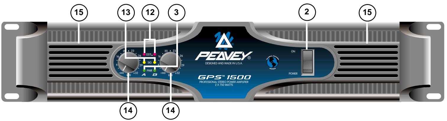
12. DDT LEDs
The DDT LEDs will illuminate when signal compression is occurring in that channel. If you have a GPS 900 or 1500 and you have the DDT compression defeated, these LED will indicate the channel is clipping.
13. SIGNAL LEDs
Each channel has a Signal LED, which comes on when the amplifier channel output exceeds 1 volt.
14. INPUT GAIN
Each channel has an Input Gain control used to adjust the gain of the input signal. Maximum power amplifier input gain (minimum sensitivity) is achieved at the full clockwise setting (30 dB or 40x ). This setting yields maximum mixer/system headroom. A setting of less than full clockwise will yield lower system noise at the expense of headroom.
15. FAN GRILL (located on front and rear panel)
Two continuously variable-speed DC fans supply cool air to the amplifier.
GPS 900 AND 1500
The fans operate at a quiet, low speed when the unit is turned on. The speed of the fans increase as the amplifier heatsinks require cooling. (See Operation Notes.)
GPS 2600, 3400 AND 3500
The fans do not operate when the unit is first turned on. The operation and speed of the fans are temperature dependent and change as the amplifier heatsinks require cooling. (See Operation Notes.)

DO NOT BLOCK THIS EXHAUST PORT! During the operation of your GPS Series amplifier, it will require fresh air intake in order for the tunnel cooling to function properly. Blocking this air exhaust port or the air intake ports on the rear could result in thermal shutdown of your amplifier.
OPERATION NOTES
AC MAINS CIRCUIT SIZE REQUIREMENTS.
Power requirements for the GPS Series amplifiers are rated at "typical" music conditions. The maximum power current draw rating is limited by the amplifier's circuit breaker. Consult the specification sheet for the current that each amplifier will demand. AC mains voltage must be the same as that indicated on the back of the amplifier. Damage caused by connecting the amplifier to improper AC voltage is not covered by any warranty.
LINE CORD
For your safety, we have incorporated a removable 3-wire line (mains) cable with proper grounding facilities. It is not advisable to remove the ground contact under any circumstances. If it is necessary to use the equipment without proper grounding facilities, suitable grounding adapters should be used. Less noise and greatly reduced shock hazard exists when the unit is operated with the proper grounded receptacles.
NOTE: Always turn off the amplifier before making audio connections. As an extra precaution, have the input attenuator turned down during power-up.
COOLING REQUIREMENTS (GPS 900 and 1500)
These GPS Series amplifiers use a forced-air cooling system to maintain a low, even operating temperature. Cooling air is drawn by synchronized, variable-speed fans mounted on the back panel, and exhausts through slots on the front panel. The fans will remain at low speed until internal operating temperature rises above 45°C . Make sure that there is enough space around the back of the amplifier to allow air to enter. The normal operating temperature is 55°C . This is a very cool temperature when compared to most amplifier standards. What this means to you is a noticeable increase in product life. On the GPS 900 and 1500 models, the fans will turn on simultaneously when temperature activated.
COOLING REQUIREMENTS (All models except GPS 900 and 1500)
These GPS Series amplifiers use a forced-air cooling system to maintain a low, even operating temperature. Cooling air is drawn by continuously variable speed fans mounted on the back panel, and exhausts through slots on the front panel. The fan will remain inactive until internal operating temperature rises above 45°C . Make sure that there is enough space around the back of the amplifier to allow air to enter. The normal operating temperature is 55°C . This is a very cool temperature when compared to most amplifier standards. What this means to you is a noticeable increase in product life.
NOTE: If the amplifier is rack-mounted, do not use doors or covers on the front or back while the unit is in operation. Whatever type of rack you are using, make sure that heated air can escape freely, and that there is no resistance to the intake of cool air through the back grill. Intake and exhaust air must flow without resistance.
INPUT CONNECTIONS
The input connector accepts balanced and unbalanced audio signals. For use with an unbalanced source, tie the inverting (-) input to ground by installing a jumper to the signal ground connection. If the inverting input is left floating, a 6 dB loss in gain will result.
GPS Series amplifiers are configured for two-channel (stereo) or bridged mode operation at the input connectors and via Mode Switch. To send the same signal to both channels, connect the input signal to Channel A via the input connector. Run a jumper from the Thru jack of Channel A to the input of Channel B. Both channels then share Channel A's input signal, but will operate independently. Speakers are connected as in two-channel (stereo) mode.
Bridged mode converts the amplifier into a single-channel unit with a power rating equal to the sum of both channels' power ratings, and at a load rating of twice that of the single-channel rating. In bridged mode, the channels operate at opposite polarity of each other so that one channel "pushes" and the other "pulls" equally. Signal is connected to the Channel A Input connector. The speakers are connected only to the designated "+" output terminals. Never ground either side of the speaker cable when the amplifier is in bridged mode, as both sides are "hot". For GPS Series amplifiers, the minimum nominal load impedance in bridged mode is 4 ohms; this is the equivalent of driving both channels at 2 ohms. Driving loads of less than 4 ohms may activate the thermal protect circuitry.
NOTE: Regardless of operating mode, NEVER connect amplifier outputs together!
SPEAKER OUTPUT CONNECTIONS
Speakers are connected using the output connectors on the rear of your amplifier. Make sure the amplifier is turned off before you change any output connections. Refer to the diagram on page 14 to view the wiring configuration of the Speakon connectors if your model utilizes them. Consult the Wire Gauge Chart on page 14 to find a suitable wire gauge and minimize losses of power in the speaker cables. Also, make sure that the load impedance is not lower than that rated for the amplifier.
PROTECTION FEATURES
The GPS Series incorporates protection features derived from Peavey's extensive experience with reliability. The amplifiers are ruggedly built from high quality components and feature comprehensive protection circuits to protect your amplifier from those "real world" occurrences.
DDT
At the amplifier's full power, or clipping point, the channel gain will automatically be reduced, guarding the loudspeakers against damaging high power and continuous square waves that would otherwise be produced. This is indicated by illumination of the DDT LED. Operation is virtually transparent in use and full signal bandwidth is maintained. However, if you have a GPS 900 or 1500 and choose to defeat the DDT compression function, this will not apply and clipping may occur.
LOAD FAULT CORRECTION
LFCTM (Load Fault Correction) is an innovative circuit that will instantaneously reduce channel gain to allow the amplifier to operate at a safe level into an abnormal load. Moderate activation of LFC is inaudible in normal use. In addition, if extreme low impedance or a short circuit is encountered during high signal level conditions, the amplifier's output relay will open.
INITIALIZATION PROTECTION™ (IP™)
IPTM operates every time the amplifier is turned on, or after a protect condition. During turn-on, the amplifier goes into protect mode and leaves the speaker load disconnected until the amplifier determines that the operating status is normal. The IPTM circuit attenuates the signal during the initial turn-on or protect operation. After relay release, channel gain gradually increases to the attenuator setting to avoid unnecessary stress on the loudspeakers.
THERMAL PROTECTION
If the heatsink temperature or power transformer reaches an abnormally high temperature, the amplifier will protect itself by disconnecting the speaker load until the amplifier returns to a normal temperature. During this time, the Power LEDs will not illuminate for that particular channel, and the cooling fan(s) will operate at maximum speed.
SHORT CIRCUIT
If an output is shorted, the LFCTM , speaker relay and thermal circuits will automatically protect the amplifier. The LFCTM circuit senses the short circuit as an abnormal load condition and reduces the channel gain to a safe level for the load. In extreme or severe conditions, the speaker relays will disconnect the load and initiate a power-on start-up sequence.
DC VOLTAGE PROTECTION
If an amplifier channel detects DC voltage or subsonic signals at its output terminals, the speaker relay will immediately open to prevent loudspeaker damage.
GPS™ Series Amplifiers
Recommended Connection for Stereo Mode
NOTE: Always use a balanced input source if available.
GPS™ Series Amplifiers Recommended Connection for Bridged Mode
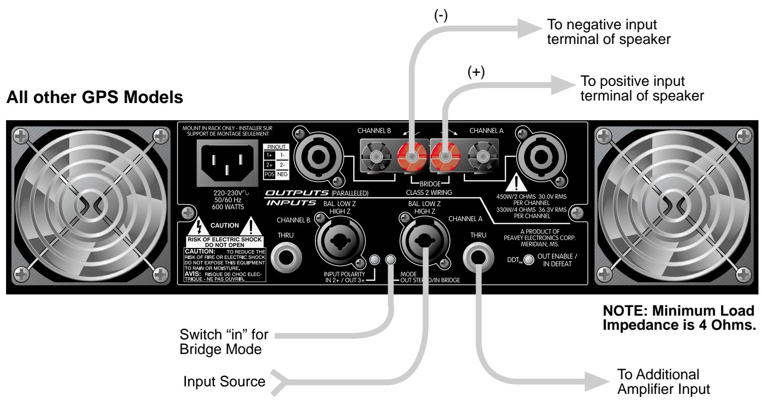
NOTE: Always use a balanced input source if available.
WIRE GAUGE CHART
| Cable Length (Feet) | Stranded Wire Gauge (AWG) | Power Loss Into 8 ohms | Power Loss Into 4 ohms | Power Loss Into 2 ohms |
| 5' | 18 AWG | .79% | 1.58% | 3.16% |
| 16 | .05 | 1.0 | 2.0 | |
| 14 | .31 | .62 | 1.24 | |
| 12 | .20 | .40 | .80 | |
| 10 | .125 | .25 | .50 | |
| 10' | 18 AWG | 1.58% | 3.16% | 6.32% |
| 16 | 1.0 | 2.0 | 4.0 | |
| 14 | .62 | 1.25 | 2.50 | |
| 12 | .40 | .80 | 1.6 | |
| 10 | .25 | .50 | 1.0 | |
| 40' | 18 AWG | 8% | 12.6% | 25.2% |
| 16 | 4.0 | 8.0 | 16.0 | |
| 14 | 2.5 | 5.0 | 10 | |
| 12 | 1.60 | 3.2 | 6.4 | |
| 10 | 1.0 | 2.0 | 4.0 | |
| 8 | .625 | 1.25 | 2.50 | |
| 80' | 16 AWG | 8.0% | 16.0% | 32.0% |
| 14 | 5.0 | 10.0 | 20.0 | |
| 12 | 3.2 | 6.4 | 12.8 | |
| 10 | 2.0 | 4.0 | 8.0 |
GPS™ 900 SPECIFICATIONS
OUTPUT POWER: (Typical value)
2 ohms, 1 kHz, .1 THD
4 ohms, 1 kHz, .1 THD
8 ohms, 1 kHz, .1 THD
4 ohms, 1 kHz, .1 THD
8 ohms, 1 kHz, .1 THD
RATED OUTPUT POWER:
4 ohms, 20Hz to 20kHz,0.03% THD
8 ohms, 20Hz to 20KHz,0.02% THD
SLEW RATE: (Typical value)
Stereo mode, each channel
Bridge mode, mono
INPUT SENSITIVITY AND IMPEDANCE:
Input attenuator set @ FCW
@ rated output power, 4 ohms
Unbalanced, 1 / 4'' phone jack
Balanced, XLR (phase selectable)
Overall system gain per channel
FREQUENCY RESPONSE: (Typical)
+0,-1 dB, 1 WRMS, 4 ohms
+0,-0.2 dB @ rated output, 4 ohms
DAMPING FACTOR: (Typical value)
8 ohms, 1kHz
HUM AND NOISE:
Below rated output power, 4 ohms
POWER CONSUMPTION:
@ 1/8 rated power @ 2 ohms
WEIGHT:
Stereo mode, both channels driven
- 450 WRMS per channel
- 330 WRMS per channel
- 200 WRMS per channel
Bridge mode, mono
- 900 WRMS
-660WRMS
Stereo mode, both channels driven
- 300 WRMS per channel
-
170 WRMS per channel
-
40 Volts per usec
-
80 Volts per usec
-
0.90 VRMS (-1 dBV)
-
20k ohms
- 10k ohms per leg
- 40X(+32dB)
Stereo mode, both channels driven
- 5Hz to 50kHz
- 20Hz to 20kHz
Stereo mode, both channels driven
- Greater than 400
Stereo mode, both channels driven
- 100 dB @ 120 volts
Stereo mode, both channels driven
-
540 watts @ 120 VAC
-
35.8 lbs. (16.2 kg)
GPS™ 1500 SPECIFICATIONS
OUTPUT POWER: (Typical value)
2 ohms, 1 kHz, .1 THD
4 ohms, 1 kHz, .1 THD
8 ohms, 1 kHz, .1 THD
4 ohms, 1 kHz, .1 THD
8 ohms, 1 kHz, .1 THD
Stereo mode, both channels driven
- 750 WRMS per channel
- 550 WRMS per channel
- 320 WRMS per channel
Bridge mode, mono
- 1,500 WRMS
- 1,100 WRMS
RATED OUTPUT POWER:
4 ohms, 20Hz to 20kHz,0.03% THD
8 ohms, 20Hz to 20kHz,0.02% THD
Stereo mode, both channels driven
- 500 WRMS per channel
- 280 WRMS per channel
SLEW RATE: (Typical value)
Stereo mode, each channel
Bridge mode, mono
- 40 Volts per usec
- 80 Volts per usec
INPUT SENSITIVITY and IMPEDANCE:
Input attenuator set @ FCW
@ rated output power, 4 ohms
Unbalanced, 1/4 " phone jack
Balanced, XLR (phase selectable)
Overall system gain per channel
- 1.17 VRMS (+1dBV)
- 20k ohms
- 10k ohms per leg
- 40X(+32dB)
FREQUENCY RESPONSE: (Typical)
+0,-1 dB, 1 WRMS, 4 ohms
+0,-0.2 dB @ rated output, 4 ohms
Stereo mode, both channels driven
- 5Hz to 50kHz
- 20Hz to 20kHz
DAMPING FACTOR: (Typical value)
8 ohms, 1kHz
Stereo mode, both channels driven
- Greater than 400
HUM AND NOISE:
Below rated output power, 4 ohms
Stereo mode, both channels driven
- 100dB ,unweighted
POWER CONSUMPTION:
@ 1/8 rated power @ 2 ohms
Stereo mode, both channels driven
- 1080 watts @ 120 VAC
WEIGHT:
- 39.2 lbs. (17.9kg)
GPS™ 2600 SPECIFICATIONS
Rated Power (2 x 2 ohms)
Rated Power (2 x 4 ohms)
Rated Power (2 x 8 ohms)
Rated Power (1 x 2 ohms)
Rated Power (1 x 4 ohms)
Rated Power (1 x 8 ohms)
Minimum Load Impedance
Maximum RMS Voltage Swing
Frequency Response
Power Bandwidth
T.H.D. (2 x 2 ohms)
T.H.D. (2 x 4 ohms)
T.H.D. (2 x 8 ohms)
Input CMRR
Voltage Gain
Crosstalk
Hum and Noise
Power Consumption
Slew Rate
Damping Factor (8 ohms)
SMPTE IMD
Input Sensitivity (x 40)
Input Impedance
Current Draw @ 1/8 power@ 2 ohms
Cooling
Controls
Indicator LEDs
Protection
Connectors
Construction
Dimensions
Weight
-
1,300 watts @ 1 kHz both channels driven at < 0.15% T.H.D.
-
950 watts @ 1 kHz both channels driven at < 0.1% T.H.D.
-
650 watts @ 1 kHz both channels driven at < 0.1% T.H.D.
-
1,500 watts @ 1 kHz at <0.1% T.H.D
-
1,000 watts @ 1 kHz at <0.1% T.H.D
-
700 watts @ 1 kHz at <0.05% T.H.D
-
2 ohms
-
93 volts
-
10Hz - 100kHz; + 0, - .3 dB at 1 watt
-
10Hz - 40kHz; + 0, - 3 dB at rated power
-
<0.15% @ 1050 watts from 20 Hz to 20 kHz with both channels driven
-
<0.1% @ 900 watts from 20 Hz to 20 kHz with both channels driven
-
<0.1% @ 600 watts from 20 Hz to 20 kHz with both channels driven
-
- 65dB @ 1 kHz
-
x 40 (32 dB)
-
-75 dB @ 1 kHz at rated power @ 8 ohms
-
-110 dB, “A” weighted referenced to rated power @ 8 ohms
-
1200 watts
-
40V/us
-
700:1 @ 20 Hz to 1 kHz
-
<0.1% 60 Hz and 7 kHz, 900W @ 4 ohms
-
1.54 volts for 4 ohm rated power, 1.27 volts for 2 ohm rated power
-
20 k ohms, balanced
-
10 A @ 120 volts
-
Two 80mm DC fans, off until heatsinks reach 45°C , then temperature dependant variable speed
-
Two front panel attenuators
-
Two Clip, two Signal, two Active
-
Thermal, DC, turn-on bursts, subsonic, incorrect loads
-
XLR input, 6.3mm phone type output patch, Speakon and Binding Post speaker output, IEC mains input
-
16 ga. steel reinforced with 12 ga.rack ears
-
133mm× 483mm× 432mm 400 mm behind rear mounting ears (5.23" x 19" x 17", 15.75" behind rack ears)
-
45.7 lbs. (20.7 kg)
GPS 3400 SPECIFICATIONS
| Rated Power (2 x 2 ohms): | 1,700 watts @ 1 kHz both channels driven at <0.15% T.H.D. |
| Rated Power (2 x 4 ohms): | 1,200 watts @ 1 kHz both channels driven at <0.1% T.H.D. |
| Rated Power (2 x 8 ohms): | 750 watts @ 1 kHz both channels driven at <0.1% T.H.D. |
| Rated Power (1 x 2 ohms): | 1,800 watts @ 1 kHz at <0.1% T.H.D |
| Rated Power (1 x 4 ohms): | 1,350 watts @ 1 kHz at <0.1% T.H.D |
| Rated Power (1 x 8 ohms): | 825 watts @ 1 kHz at <0.05% T.H.D |
| T.H.D. (2 x 2 ohms): | <0.15% @ 1350W from 20 Hz to 20 kHz with both channels driven |
| T.H.D. (2 x 4 ohms): | <0.1% @ 1000W from 20 Hz to 20 kHz with both channels driven |
| T.H.D. (2 x 8 ohms): | <0.08% @ 700W from 20 Hz to 20 kHz with both channels driven |
| Input CMRR: | > -65 dB @ 1 kHz |
| Voltage Gain: | x 40 (32 dB) |
| Crosstalk: | > -75 dB @ 1 kHz at rated power @ 8 ohms |
| Hum and Noise: | > -115 dB, “A” weighted referenced to rated power @ 8 ohms |
| Power Consumption: | > 1400 watts |
| Slew Rate: | > 40V/us |
| Damping Factor (8 ohms): | > 325:1 @ 20 Hz - 1 kHz |
| SMPTE IMD: | <0.1% 60Hz and 7 kHz, 950W @ 4 ohms |
| Input Sensitivity (x 40): | 1.7 volts for 4 ohm rated power, 1.4 volts for 2 ohm rated power |
| Input Impedance: | 20 k ohms, balanced |
| Current Draw @ 1/8 rated power @ 2 ohms: | 11.66 A @ 120 volts |
| Cooling: | Two 80 mm DC fans, off until heatsinks reach 45°C, then temperature dependent variable speed |
| Controls: | Two front panel attenuators |
| Indicator LEDs: | Two DDT/Clip, 2 Signal, 2 Power |
| Protection: | Thermal, DC, turn-on bursts, subsonic, incorrect loads |
| Connectors: | XLR input, 6.3mm phone type output patch, Speakon and Binding Post speaker output, IEC mains input |
| Construction: | 16 ga. steel reinforced with 12 ga.rack ears |
| Dimensions: | 133 mm x 483 mm x 432 mm, 400 mm behind rear mounting ears (5.23" x 19" x 17", 15.75" behind rack ears) |
| Weight: | 49.8 lbs. (23.3 kg) |
GPS 3500 SPECIFICATIONS
| Rated Power (2 x 2 ohms): | 1750 watts @ 1 kHz both channels driven at <0.15% T.H.D. |
| Rated Power (2 x 4 ohms): | 1200 watts @ 1 kHz both channels driven at <0.1% T.H.D. |
| Rated Power (2 x 8 ohms): | 775 watts @ 1 kHz both channels driven at <0.1% T.H.D. |
| Rated Power (1 x 2 ohms): | 1,850 watts @ 1 kHz at <0.1% T.H.D |
| Rated Power (1 x 4 ohms): | 1,350 watts @ 1 kHz at <0.1% T.H.D |
| Rated Power (1 x 8 ohms): | 850 watts @ 1 kHz at <0.05% T.H.D |
| Minimum Load Impedance: | 2 ohms |
| Maximum RMS Voltage Swing: | 89 volts |
| Frequency Response: | 10 Hz - 100 kHz; +0, -3d B at 1 watt |
| Power Bandwidth: | 10 Hz - 40 kHz; +0, -3 dB at rated power |
| T.H.D. (2 x 2 ohms): | <0.15% @ 1400W from 20 Hz to 20 kHz with both channels driven |
| T.H.D. (2 x 4 ohms): | <0.1% @ 1050W from 20 Hz to 20 kHz with both channels driven |
| T.H.D. (2 x 8 ohms): | <0.08% @ 750W from 20 Hz to 20 kHz with both channels driven |
| Input CMRR: | > -65 dB @ 1 kHz |
| Voltage Gain: | x 40 (32 dB) |
| Crosstalk: | > -75 dB @ 1 kHz at rated power @ 8 ohms |
| Hum and Noise: | > -115 dB, “A” weighted referenced to rated power @ 8 ohms |
| Power Consumption: | > 1400 watts |
| Slew Rate: | > 40V/us |
| Damping Factor (8 ohms): | > 325:1 @ 20 Hz - 1 kHz |
| SMPTE IMD: | <0.1% 60Hz and 7 kHz, 950W @ 4 ohms |
| Input Sensitivity (x 40): | 1.7 volts for 4 ohm rated power, 1.4 volts for 2 ohm rated power |
| Input Impedance: | 20 k ohms, balanced |
| Current Draw @ 1/8 rated power @ 2 ohms: | 11.66 A @ 120 volts |
| Cooling: | Two 80 mm DC fans, off until heatsinks reach 45°C, then temperature dependent variable speed |
| Controls: | Two front panel attenuators |
| Indicator LEDs: | Two DDT/Clip, 2 Signal, 2 Power |
| Protection: | Thermal, DC, turn-on bursts, subsonic, incorrect loads |
| Connectors: | XLR input, 6.3mm phone type output patch, Speakon and Binding Post speaker output, IEC mains input |
| Construction: | 16 ga. steel reinforced with 12 ga.rack ears |
| Dimensions: | 133 mm x 483 mm x 432 mm, 400 mm behind rear mounting ears (5.23" x 19" x 17", 15.75" behind rack ears) |
| Weight: | 51.3 lbs. (23.3 kg) |
ESPAÑOL
Serie GPS
| SPECIFICATIONS | GPS™ 900 | GPS™ 1500 | GPS™ 2600 | GPS™ 3500 |
| OUTPUT POWER | ||||
| Stereo mode, both channels driven | ||||
| 2 ohms, 1 kHz, 0.1% THD | 450W RMS per channel | 750W RMS per channel | 1300W RMS per channel | 1700W RMS per channel |
| 4 ohms, 1 kHz, 0.1% THD | 330W RMS per channel | 550W RMS per channel | 950W RMS per channel | 1200W RMS per channel |
| 8 ohms, 1 kHz, 0.1% THD | 200W RMS per channel | 320W RMS per channel | 620W RMS per channel | 775W RMS per channel |
| Bridge mode, mono | ||||
| 4 ohms, 1 kHz, 0.1% THD | 900W RMS | 1500W RMS | 2600W RMS | 3500W RMS |
| 8 ohms, 1 kHz, 0.1% THD | 660W RMS | 1100W RMS | 1900W RMS | 2400W RMS |
| RATED OUTPUT POWER: | ||||
| Stereo mode, both channels driven | ||||
| 4 ohms, 20 Hz to 20 kHz, 0.03% THD | 300W RMS per channel | 500W RMS per channel | 900W RMS per channel | 1050W RMS per channel |
| 8 ohms, 20 Hz to 20 kHz, 0.02% THD | 1700W RMS per channel | 280W RMS per channel | 600W RMS per channel | 750W RMS per channel |
| 4 ohms, 20 Hz to 20 kHz, 0.1% THD | ||||
| 8 ohms, 20 Hz to 20 kHz, 0.08% THD | ||||
| SLEW RATE:(Typical value) | ||||
| Stereo mode, each channel | 40 Volts per μsec | 40 Volts per μsec | 40 Volts per μsec | 40 Volts per μsec |
| Bridge mode, mono | 80 Volts per μsec | 80 Volts per μsec | 80 Volts per μsec | 80 Volts per μsec |
| INPUT SENSITIVITY & IMPEDANCE: | ||||
| @ rated output power, 4 ohms | 0.87V RMS | 1.12V RMS | 1.54V RMS | 1.62V RMS |
| unbalanced, 1/4" phone jack | 20 k ohms | 20 k ohms | 20 k ohms | 20 k ohms |
| Balanced, XLR (polarity selectable) | 10 k ohms per leg | 10 k ohms per leg | 10 k ohms per leg | 10 k ohms per leg |
| Overall system gain per channel | 40X (+32 dB) | 40X (+32 dB) | 40X (-32 dB) | 40X (+32 dB) |
| FREQUENCY RESPONSE: | ||||
| Stereo mode, both channels driven | ||||
| +0m -1 dB @ 1 WRMS, 4 ohms | 5 Hz to 50 kHz | 5 Hz to 50 kHz | 5 Hz to 100 kHz | 5 Hz to 100 kHz |
| +0, -0.2 dB @ rated output, 4 ohms | 20 Hz to 20 kHz | 20 Hz to 20 kHz | 10 Hz to 30 kHz | 10 Hz to 30 kHz |
| DAMPING FACTOR: (Typical value) | ||||
| Stereo mode, both channels driven | Greater than 400 | Greater than 400 | Greater than 700 | Greater than 325 |
| 8 ohms | ||||
| Hum & Noise: | ||||
| Stereo mode, both channels driven | ||||
| Below rated output power, 4 ohms | 100 dB, unweighted | 100 dB, unweighted | 100 dB, unweighted | 100 dB, unweighted |
| Cable Length (Feet) | Stranded Wire Gauge (AWG) | Power Loss Into 8 ohms | Power Loss Into 4 ohms | Power Loss Into 2 ohms |
| 5' | 18 AWG | .79% | 1.58% | 3.16% |
| 16 | .05 | 1.0 | 2.0 | |
| 14 | .31 | .62 | 1.24 | |
| 12 | .20 | .40 | .80 | |
| 10 | .125 | .25 | .50 | |
| 10' | 18 AWG | 1.58% | 3.16% | 6.32% |
| 16 | 1.0 | 2.0 | 4.0 | |
| 14 | .62 | 1.25 | 2.50 | |
| 12 | .40 | .80 | 1.6 | |
| 10 | .25 | .50 | 1.0 | |
| 40' | 18 AWG | 8% | 12.6% | 25.2% |
| 16 | 4.0 | 8.0 | 16.0 | |
| 14 | 2.5 | 5.0 | 10 | |
| 12 | 1.60 | 3.2 | 6.4 | |
| 10 | 1.0 | 2.0 | 4.0 | |
| 8 | .625 | 1.25 | 2.50 | |
| 80' | 16 AWG | 8.0% | 16.0% | 32.0% |
| 14 | 5.0 | 10.0 | 20.0 | |
| 12 | 3.2 | 6.4 | 12.8 | |
| 10 | 2.0 | 4.0 | 8.0 |
4 ohmios, 20Hz a 20kHz,0.03% THD
8 ohmios, 20Hz a 20KHz,0.02% THD
RAZON SLEW: (Valor Túpico)
2 ohmios, 1kHz 1% THD
4 ohmios, 1 kHz, 1% THD
8 ohmios, 1 kHz, 1% THD
4 ohmios, 1kHz 1% THD
8 ohmios, 1 kHz, 1% THD
4 ohmios, 20Hz to 20kHz,0.03% THD
8 ohmios, 20Hz to 20kHz,0.02% THD
T.H.D. (2 x 2 ohmios):
T.H.D. (2 x 4 ohmios):
T.H.D. (2 x 8 ohmios):
Entrada CMRR:
Factor Damping (8 ohmios):
SMPTE IMD:
51.3 lbs. (23.3kg)
T.H.D. (2 x 2 ohmios):
T.H.D. (2 x 4 ohmios):
T.H.D. (2 x 8 ohmios):
Entrada CMRR:
T.H.D. (2 x 2 ohmios):
T.H.D. (2 x 4 ohmios):
T.H.D. (2 x 8 ohmios):
Entrada CMRR:
51.3 lbs. (23.3kg)
FRANÇAIS
Série GPS
| SPECIFICATIONS | GPS™ 900 | GPS™ 1500 | GPS™ 2600 | GPS™ 3500 |
| OUTPUT POWER | ||||
| Stereo mode, both channels driven | ||||
| 2 ohms, 1 kHz, 0.1% THD | 450W RMS per channel | 750W RMS per channel | 1300W RMS per channel | 1700W RMS per channel |
| 4 ohms, 1 kHz, 0.1% THD | 330W RMS per channel | 550W RMS per channel | 950W RMS per channel | 1200W RMS per channel |
| 8 ohms, 1 kHz, 0.1% THD | 200W RMS per channel | 320W RMS per channel | 620W RMS per channel | 775W RMS per channel |
| Bridge mode, mono | ||||
| 4 ohms, 1 kHz, 0.1% THD | 900W RMS | 1500W RMS | 2600W RMS | 3500W RMS |
| 8 ohms 1 kHz, 0.1% THD | 660W RMS | 1100W RMS | 1900W RMS | 2400W RMS |
| RATED OUTPUT POWER: | ||||
| Stereo mode, both channels driven | ||||
| 4 ohms, 20 Hz to 20 kHz, 0.03% THD | 300W RMS per channel | 500W RMS per channel | 900W RMS per channel | 1050W RMS per channel |
| 8 ohms, 20 Hz to 20 kHz, 0.02% THD | 1700W RMS per channel | 280W RMS per channel | 600W RMS per channel | 750W RMS per channel |
| 4 ohms, 20 Hz to 20 kHz, 0.1% THD | ||||
| 8 ohms, 20 Hz to 20 kHz, 0.08% THD | ||||
| SLEW RATE:(Typical value) | ||||
| Stereo mode, each channel | 40 Volts per μsec | 40 Volts per μsec | 40 Volts per μsec | 40 Volts per μsec |
| Bridge mode, mono | 80 Volts per μsec | 80 Volts per μsec | 80 Volts per μsec | 80 Volts per μsec |
| INPUT SENSITIVITY & IMPEDANCE: | ||||
| @ rated output power, 4 ohms | 0.87V RMS | 1.12V RMS | 1.54V RMS | 1.62V RMS |
| unbalanced, 1/4" phone jack | 20 k ohms | 20 k ohms | 20 k ohms | 20 k ohms |
| Balanced, XLR (polarity selectable) | 10 k ohms per leg | 10 k ohms per leg | 10 k ohms per leg | 10 k ohms per leg |
| Overall system gain per channel | 40X (+32 dB) | 40X (+32 dB) | 40X (-32 dB) | 40X (+32 dB) |
| FREQUENCY RESPONSE: | ||||
| Stereo mode, both channels driven | ||||
| +0m-1 dB @ 1 WRMS, 4 ohms | 5 Hz to 50 kHz | 5 Hz to 50 kHz | 5 Hz to 100 kHz | 5 Hz to 100 kHz |
| +0,-0.2 dB @ rated output, 4 ohms | 20 Hz to 20 kHz | 20 Hz to 20 kHz | 10 Hz to 30 kHz | 10 Hz to 30 kHz |
| DAMPING FACTOR: (Typical value) | ||||
| Stereo mode, both channels driven | Greater than 400 | Greater than 400 | Greater than 700 | Greater than 325 |
| 8 ohms | ||||
| Hum & Noise: | ||||
| Stereo mode, both channels driven | ||||
| Below rated output power, 4 ohms | 100 dB, unweighted | 100 dB, unweighted | 100 dB, unweighted | 100 dB, unweighted |
| Cable Length (Feet) | Stranded Wire Gauge (AWG) | Power Loss Into 8 ohms | Power Loss Into 4 ohms | Power Loss Into 2 ohms |
| 5' | 18 AWG | .79% | 1.58% | 3.16% |
| 16 | .05 | 1.0 | 2.0 | |
| 14 | .31 | .62 | 1.24 | |
| 12 | .20 | .40 | .80 | |
| 10 | .125 | .25 | .50 | |
| 10' | 18 AWG | 1.58% | 3.16% | 6.32% |
| 16 | 1.0 | 2.0 | 4.0 | |
| 14 | .62 | 1.25 | 2.50 | |
| 12 | .40 | .80 | 1.6 | |
| 10 | .25 | .50 | 1.0 | |
| 40' | 18 AWG | 8% | 12.6% | 25.2% |
| 16 | 4.0 | 8.0 | 16.0 | |
| 14 | 2.5 | 5.0 | 10 | |
| 12 | 1.60 | 3.2 | 6.4 | |
| 10 | 1.0 | 2.0 | 4.0 | |
| 8 | .625 | 1.25 | 2.50 | |
| 80' | 16 AWG | 8.0% | 16.0% | 32.0% |
| 14 | 5.0 | 10.0 | 20.0 | |
| 12 | 3.2 | 6.4 | 12.8 | |
| 10 | 2.0 | 4.0 | 8.0 |
SPECIFICATIONS DU GPS™ 900
2 ohms, 1 kHz, 1% THD
4 ohms, 1 kHz, 1% THD
8 ohms, 1kHz 1% THD
4 ohms, 1 kHz, 1% THD
8 ohms, 1kHz 1% THD
8 ohms, 1kHz
2 ohms, 1 kHz, 1% THD
4 ohms, 1 kHz, 1% THD
8 ohms, 1 kHz, 1% THD
4 ohms, 1 kHz, 1% THD
8 ohms, 1 kHz, 1% THD
8 ohms, 1kHz
T.H.D. (2 x 2 ohms):
T.H.D. (2 x 4 ohms):
T.H.D. (2 x 8 ohms):
RRMC entrée:
Gain de tension:
Diaphonie:
T.H.D. (2 x 2 ohms):
T.H.D. (2 x 4 ohms):
T.H.D. (2 x 8 ohms):
RRMC entrée:
Gain de tension:
Diaphonie:
| SPECIFICATIONS | GPS™ 900 | GPS™ 1500 | GPS™ 2600 | GPS™ 3500 |
| OUTPUT POWER | ||||
| Stereo mode, both channels driven | ||||
| 2 ohms, 1 kHz, 0.1% THD | 450W RMS per channel | 750W RMS per channel | 1300W RMS per channel | 1700W RMS per channel |
| 4 ohms, 1 kHz, 0.1% THD | 330W RMS per channel | 550W RMS per channel | 950W RMS per channel | 1200W RMS per channel |
| 8 ohms, 1 kHz, 0.1% THD | 200W RMS per channel | 320W RMS per channel | 620W RMS per channel | 775W RMS per channel |
| Bridge mode, mono | ||||
| 4 ohms, 1 kHz, 0.1% THD | 900W RMS | 1500W RMS | 2600W RMS | 3500W RMS |
| 8 ohms 1 kHz, 0.1% THD | 660W RMS | 1100W RMS | 1900W RMS | 2400W RMS |
| RATED OUTPUT POWER: | ||||
| Stereo mode, both channels driven | ||||
| 4 ohms, 20 Hz to 20 kHz, 0.03% THD | 300W RMS per channel | 500W RMS per channel | 900W RMS per channel | 1050W RMS per channel |
| 8 ohms, 20 Hz to 20 kHz, 0.02% THD | 1700W RMS per channel | 280W RMS per channel | 600W RMS per channel | 750W RMS per channel |
| 4 ohms, 20 Hz to 20 kHz, 0.1% THD | ||||
| 8 ohms, 20 Hz to 20 kHz, 0.08% THD | ||||
| SLEW RATE:(Typical value) | ||||
| Stereo mode, each channel | 40 Volts per μsec | 40 Volts per μsec | 40 Volts per μsec | 40 Volts per μsec |
| Bridge mode, mono | 80 Volts per μsec | 80 Volts per μsec | 80 Volts per μsec | 80 Volts per μsec |
| INPUT SENSITIVITY & IMPEDANCE: | ||||
| @ rated output power, 4 ohms | 0.87V RMS | 1.12V RMS | 1.54V RMS | 1.62V RMS |
| unbalanced, 1/4" phone jack | 20 k ohms | 20 k ohms | 20 k ohms | 20 k ohms |
| Balanced, XLR (polarity selectable) | 10 k ohms per leg | 10 k ohms per leg | 10 k ohms per leg | 10 k ohms per leg |
| Overall system gain per channel | 40X (+32 dB) | 40X (+32 dB) | 40X (-32 dB) | 40X (+32 dB) |
| FREQUENCY RESPONSE: | ||||
| Stereo mode, both channels driven | ||||
| +0m -1 dB @ 1 WRMS, 4 ohms | 5 Hz to 50 kHz | 5 Hz to 50 kHz | 5 Hz to 100 kHz | 5 Hz to 100 kHz |
| +0, -0.2 dB @ rated output, 4 ohms | 20 Hz to 20 kHz | 20 Hz to 20 kHz | 10 Hz to 30 kHz | 10 Hz to 30 kHz |
| DAMPING FACTOR: (Typical value) | ||||
| Stereo mode, both channels driven | Greater than 400 | Greater than 400 | Greater than 700 | Greater than 325 |
| 8 ohms | ||||
| Hum & Noise: | ||||
| Stereo mode, both channels driven | ||||
| Below rated output power, 4 ohms | 100 dB, unweighted | 100 dB, unweighted | 100 dB, unweighted | 100 dB, unweighted |
This is a proof of Theorem 1.2.1. This is the same as in [10]. Moreover, it is also a consequence of Theorem 1.1.
LOAD-FAULT-CORRECTION
Initialization-Protection (IPTM)
| Cable Length (Feet) | Stranded Wire Gauge (AWG) | Power Loss Into 8 ohms | Power Loss Into 4 ohms | Power Loss Into 2 ohms |
| 5' | 18 AWG | .79% | 1.58% | 3.16% |
| 16 | .05 | 1.0 | 2.0 | |
| 14 | .31 | .62 | 1.24 | |
| 12 | .20 | .40 | .80 | |
| 10 | .125 | .25 | .50 | |
| 10' | 18 AWG | 1.58% | 3.16% | 6.32% |
| 16 | 1.0 | 2.0 | 4.0 | |
| 14 | .62 | 1.25 | 2.50 | |
| 12 | .40 | .80 | 1.6 | |
| 10 | .25 | .50 | 1.0 | |
| 40' | 18 AWG | 8% | 12.6% | 25.2% |
| 16 | 4.0 | 8.0 | 16.0 | |
| 14 | 2.5 | 5.0 | 10 | |
| 12 | 1.60 | 3.2 | 6.4 | |
| 10 | 1.0 | 2.0 | 4.0 | |
| 8 | .625 | 1.25 | 2.50 | |
| 80' | 16 AWG | 8.0% | 16.0% | 32.0% |
| 14 | 5.0 | 10.0 | 20.0 | |
| 12 | 3.2 | 6.4 | 12.8 | |
| 10 | 2.0 | 4.0 | 8.0 |
GPS™ 900 SPEZIFIKATIONEN
2 Ohm, 1 kHz, 1% THD
4 Ohm, 1 kHz, 1% THD
8 Ohm, 1 kHz, 1% THD
4 Ohm, 1 kHz, 1% THD
8 Ohm, 1 kHz, 1% THD
2 Ohm, 1 kHz, 1% THD
4 Ohm, 1 kHz, 1% THD
8 Ohm, 1 kHz, 1% THD
4 Ohm, 1 kHz, 1% THD
8 Ohm, 1 kHz, 1% THD
Effective Date: July 1, 1998
What This Warranty Covers
Your Peavey Warranty covers defects in material and workmanship in Peavey products purchased and serviced in the U.S.A. and Canada.
What This Warranty Does Not Cover
The Warranty does not cover: (1) damage caused by accident, misuse, abuse, improper installation or operation, rental, product modification or neglect; (2) damage occurring during shipment; (3) damage caused by repair or service performed by persons not authorized by Peavey; (4) products on which the serial number has been altered, defaced or removed; (5) products not purchased from an Authorized Peavey Dealer.
Who This Warranty Protects
This Warranty protects only the original retail purchaser of the product.
How Long This Warranty Lasts
The Warranty begins on the date of purchase by the original retail purchaser. The duration of the Warranty is as follows:
| Product Category | Duration |
| Guitars/Basses, Amplifiers, Pre-Amplifiers, Mixers, Electronic Crossovers and Equalizers | 2 years * (+ 3 years) |
| Drums | 2 years * (+ 1 year) |
| Enclosures | 3 years * (+ 2 years) |
| Digital Effect Devices and Keyboard and MIDI Controllers | 1 year * (+ 1 year) |
| Microphones | 2 years |
| Speaker Components (incl. speakers, baskets, drivers, diaphragm replacement kits and passive crossovers) and all Accessories | 1 year |
| Tubes and Meters | 90 days |
[denotes additional warranty period applicable if optional Warranty Registration Card is completed and returned to Peavey by original retail purchaser within 90 days of purchase.]
What Peavey Will Do
We will repair or replace (at Peavey's discretion) products covered by warranty at no charge for labor or materials. If the product or component must be shipped to Peavey for warranty service, the consumer must pay initial shipping charges. If the repairs are covered by warranty, Peavey will pay the return shipping charges.
How To Get Warranty Service
(1) Take the defective item and your sales receipt or other proof of date of purchase to your Authorized Peavey Dealer or Authorized Peavey Service Center.
OR
(2) Ship the defective item, prepaid, to Peavey Electronics Corporation, International Service Center, 412 Highway 11 & 80 East, Meridian, MS 39301 or Peavey Canada Ltd., 95 Shields Court, Markham, Ontario, Canada L3R 9T5. Include a detailed description of the problem, together with a copy of your sales receipt or other proof of date of purchase as evidence of warranty coverage. Also provide a complete return address.
Limitation of Implied Warranties
ANY IMPLIED WARRANTYES, INCLUDING WARRANTYES OF MERCHANTABILITY AND FITNESS FOR A PARTICULAR PURPOSE, ARE LIMITED IN DURATION TO THE LENGTH OF THIS WARRANTY.
Some states do not allow limitations on how long an implied warranty lasts, so the above limitation may not apply to you.
Exclusions of Damages
PEAVEY'S LIABILITY FOR ANY DEFECTIVE PRODUCT IS LIMITED TO THE REPAIR OR REPLACEMENT OF THE PRODUCT, AT PEAVEY'S OPTION. IF WE ELECT TO REPLACE THE PRODUCT, THE REPLACEMENT MAY BE A RECONDITIONED UNIT. PEAVEY SHALL NOT BE LIABLE FOR DAMAGES BASED ON INCONVENIENCE, LOSS OF USE, LOST PROFITS, LOST SAVINGS, DAMAGE TO ANY OTHER EQUIPMENT OR OTHER ITEMS AT THE SITE OF USE, OR ANY OTHER DAMAGES WHETHER INCIDENTAL, CONSEQUENTIAL OR OTHERWISE, EVEN IF PEAVEY HAS BEEN ADVISED OF THE POSSIBILITY OF SUCH DAMAGES.
Some states do not allow the exclusion or limitation of incidental or consequential damages, so the above limitation or exclusion may not apply to you.
This Warranty gives you specific legal rights, and you may also have other rights which vary from state to state.
If you have any questions about this warranty or service received or if you need assistance in locating an Authorized Service Center, please contact the Peavey International Service Center at (601) 483-5365 / Peavey Canada Ltd. at (905) 475-2578.
Features and specifications subject to change without notice.
IMPORTANT SAFETY INSTRUCTIONS
WARNING: When using electric products, basic cautions should always be followed, including the following:
- Read these instructions.
- Keep these instructions.
- Heed all warnings.
- Follow all instructions.
- Do not use this apparatus near water. For example, near or in a bathtub, swimming pool, sink, wet basement, etc.
- Clean only with a damp cloth.
- Do not block any of the ventilation openings. Install in accordance with manufacturer's instructions. It should not be placed flat against a wall or placed in a built-in enclosure that will impede the flow of cooling air.
- Do not install near any heat sources such as radiators, heat registers, stoves or other apparatus (including amplifiers) that produce heat.
- Do not defeat the safety purpose of the polarized or grounding-type plug. A polarized plug has two blades with one wider than the other. A grounding type plug has two blades and a third grounding plug. The wide blade or third prong is provided for your safety. When the provided plug does not fit into your inlet, consult an electrician for replacement of the obsolete outlet. Never break off the grounding. Write for our free booklet "Shock Hazard and Grounding". Connect only to a power supply of the type marked on the unit adjacent to the power supply cord.
- Protect the power cord from being walked on or pinched, particularly at plugs, convenience receptacles, and the point they exit from the apparatus.
- Only use attachments/accessories provided by the manufacturer.
- Use only with a cart, stand, tripod, bracket, or table specified by the manufacturer, or sold with the apparatus. When a cart is used, use caution when moving the cart/apparatus combination to avoid injury from tip-over.
- Unplug this apparatus during lightning storms or when unused for long periods of time.
- Refer all servicing to qualified service personnel. Servicing is required when the apparatus has been damaged in any way, such as power-supply cord or plug is damaged, liquid has been spilled or objects have fallen into the apparatus, the apparatus has been exposed to rain or moisture, does not operate normally, or has been dropped.
- If this product is to be mounted in an equipment rack, rear support should be provided.
- Exposure to extremely high noise levels may cause a permanent hearing loss. Individuals vary considerably in susceptibility to noise-induced hearing loss, but nearly everyone will lose some hearing if exposed to sufficiently intense noise for a sufficient time. The U.S. Government's Occupational and Health Administration (OSHA) has specified the following permissible noise level exposures:
Duration Per Day In Hours
8
6
4
3
2
1 1/2
1
1/2
1/4 or less
Sound Level dBA, Slow Response
90
92
95
97
100
102
105
110
115
According to OSHA, any exposure in excess of the above permissible limits could result in some hearing loss. Ear plugs or protectors to the ear canals or over the ears must be worn when operating this amplification system in order to prevent a permanent hearing loss, if exposure is in excess of the limits as set forth above. To ensure against potentially dangerous exposure to high sound pressure levels, it is recommended that all persons exposed to equipment capable of producing high sound pressure levels such as this amplification system be protected by hearing protectors while this unit is in operation.
SAVE THESE INSTRUCTIONS!

PEAVEY
Features and specifications subject to change without notice.
Peavey Electronics Corporation • 711 A Street • Meridian • MS • 39301
(601) 483-5365 • FAX (601) 486-1278 • www.peavey.com

80304679

- GPS™ Series Amplifiers
- UNPACKING/REGISTRATION
- INSTALLATION AND MOUNTING
- QUICK START
- TO SET UP THE AMPLIFIER FOR BASIC USAGE:
- AC POWER
- REMOVABLE AC POWER CORD (Located on the rear of the unit)
- AC POWER SWITCH (Located on the front of the unit. See diagram on page 9.)
- POWER LED (Located on the front of the unit. See diagram on page 9.)
- REAR PANEL
- THE INS AND OUTS OF MODE SELECTION
- MODE SELECTION
- MODE SWITCH
- STEREO:
- BRIDGED OR MONO:
- NOTE FOR GPS 900 AND 1500:
- INPUTS
- CHANNEL A COMBINATION INPUT
- GPS 900 AND 1500
- GPS 2600, 3400 AND 3500
- CHANNEL B COMBINATION INPUT
- INPUT POLARITY
- THRU
- OUTPUTS
- SPEAKER OUTPUT CONNECTORS
- GPS 900 OR GPS 1500 120 VAC (DOMESTIC) MODELS:
- All other GPS models:
- BINDING POST OUTPUT CONNECTORS
- DDT COMPRESSION
- DDT DEFEAT
- FRONT PANEL CONTROLS/INDICATORS
- DDT LEDs
- SIGNAL LEDs
- INPUT GAIN
- FAN GRILL (located on front and rear panel)
- OPERATION NOTES
- AC MAINS CIRCUIT SIZE REQUIREMENTS.
- LINE CORD
- COOLING REQUIREMENTS (GPS 900 and 1500)
- COOLING REQUIREMENTS (All models except GPS 900 and 1500)
- INPUT CONNECTIONS
- SPEAKER OUTPUT CONNECTIONS
- PROTECTION FEATURES
- DDT
- LOAD FAULT CORRECTION
- INITIALIZATION PROTECTION™ (IP™)
- THERMAL PROTECTION
- SHORT CIRCUIT
- DC VOLTAGE PROTECTION
- Recommended Connection for Stereo Mode
- GPS™ 900 SPECIFICATIONS
- OUTPUT POWER: (Typical value)
- RATED OUTPUT POWER:
- SLEW RATE: (Typical value)
- INPUT SENSITIVITY AND IMPEDANCE:
- FREQUENCY RESPONSE: (Typical)
- DAMPING FACTOR: (Typical value)
- HUM AND NOISE:
- POWER CONSUMPTION:
- Stereo mode, both channels driven
- Bridge mode, mono
- GPS™ 1500 SPECIFICATIONS
- GPS™ 2600 SPECIFICATIONS
- GPS 3400 SPECIFICATIONS
- GPS 3500 SPECIFICATIONS
- ESPAÑOL
- Serie GPS
- RAZON SLEW: (Valor Túpico)
- FRANÇAIS
- Série GPS
- SPECIFICATIONS DU GPS™ 900
- LOAD-FAULT-CORRECTION
- Initialization-Protection (IPTM)
- GPS™ 900 SPEZIFIKATIONEN
- What This Warranty Covers
- What This Warranty Does Not Cover
- Who This Warranty Protects
- How Long This Warranty Lasts
- What Peavey Will Do
- How To Get Warranty Service
- OR
- Limitation of Implied Warranties
- Exclusions of Damages
- IMPORTANT SAFETY INSTRUCTIONS
- SAVE THESE INSTRUCTIONS!
- PEAVEY
Brand : PEAVEY
Model : GPS
Category : Amplifier