
CT-S4000L - Thermal printer CITIZEN - Free user manual and instructions
Find the device manual for free CT-S4000L CITIZEN in PDF.

| Product type | Online thermal printer |
| Brand | CITIZEN |
| Model | CT-S4000L |
| Print method | Line thermal |
| Print speed | Up to 150 mm/s |
| Print width | 104 mm / 832 dots, 72 mm / 576 dots, 50 mm / 400 dots |
| Paper width | 112 mm, 82.5 mm, 80 mm, 58 mm (label model) |
| Roll diameter | Maximum 102 mm |
| Interfaces | USB, RS-232C (serial), IEEE1284 (parallel) |
| Cash drawer interface | 2 cash drawers supported |
| Auto cutter | Yes, partial and full cut |
| Power supply | AC 100-240 V, 50/60 Hz, 130 VA |
| Power consumption | Approx. 70 W (normal printing) |
| Weight | Approx. 2.3 kg |
| Dimensions (W × D × H) | 177 × 213 × 147 mm |
| Operating temperature | 5 to 45 °C |
| Operating humidity | 10 to 90% RH (non-condensing) |
| Barcode types | UPC-A/E, EAN 13/8, ITF, CODE 39, CODE 128, CODABAR, CODE 93, PDF417, QR Code |
| User memory | 384 KB for custom characters and logos |
| Cleaning | Thermal head: cotton swab soaked in ethyl alcohol; sensors: moist cotton swab |
| Print head life | 100 km or 100 million pulses |
| Auto cutter life | 1,000,000 cuts |
Frequently Asked Questions - CT-S4000L CITIZEN
- Steady on: paper end or paper nearly empty.
- Flashing: cover open, cutter jam, head overheating, paper jam, or detection error (label/black mark). Refer to the manual for the specific flash code.
User questions about CT-S4000L CITIZEN
0 question about this device. Answer the ones you know or ask your own.
Ask a new question about this device
Download the instructions for your Thermal printer in PDF format for free! Find your manual CT-S4000L - CITIZEN and take your electronic device back in hand. On this page are published all the documents necessary for the use of your device. CT-S4000L by CITIZEN.
USER MANUAL CT-S4000L CITIZEN
LINE THERMAL PRINTER
MODEL CT-S4000/CT-S4000DC
CT-S4000L/CT-S4000DCL
CT-S4000M/CT-S4000DCM
User's Manual
Mode d'emploi
Benutzerhandbuch
Manuale dell'utente
Manual de Usuario
natural_image
Line drawing of a rectangular electronic device with ports and a lid (no text or symbols)Declaration of Conformity
This printer conforms to the following Standards:
Low Voltage Directive 73/23/EEC, 93/68/EEC and the EMC Directive 89/336/EEC, 92/31/EEC, 93/68/EEC.
LVD : EN60950-1
EMC : EN55022 Class A
EN61000-3-2
EN61000-3-3
EN55024
This declaration is applied only for 230V model.
IMPORTANT: This equipment generates, uses, and can radiate radio frequency energy and if not installed and used in accordance with the instruction manual, may cause interference to radio communications. It has been tested and found to comply with the limits for a Class A computing device pursuant to Subpart J of Part 15 of FCC Rules, which are designed to provide reasonable protection against such interference when operated in a commercial environment. Operation of this equipment in a residential area is likely to cause interference, in which case the user at his own expense will be required to take whatever measures may be necessary to correct the interference.
CAUTION: Use shielded cable for this equipment.
Sicherheitshinweis
This Class A digital apparatus complies with Canadian ICES-003.
This digital apparatus does not exceed the class A limits for radio noise emissions from digital apparatus, as set out in the radio interference regulations of the Canadian department of communications.
- Before using this product, be sure to read through this manual. After having read this manual, keep it in a safe, readily accessible place for future reference.
● The information contained herein is subject to change without prior notice.
● Reproduction or transfer of part or all of this document in any means is prohibited without permission from Citizen Systems.
● Note that Citizen Systems is not responsible for any operation results regardless of missing, error, or misprinting in this manual.
● Note that Citizen Systems is not responsible for any trouble caused as a result of using options or consumables that are not specified in this manual. - Except explained elsewhere in this manual, do not attempt to service, disassemble, or repair this product.
● Note that Citizen Systems is not responsible for any damage attributable to incorrect operation/handling or improper operating environments that are not specified in this manual.
● Data is basically for temporary use and not stored for an extended period of time or permanently. Please note that Citizen Systems is not responsible for damage or lost profit resulting from the loss of data caused by accidents, repairs, tests or other occurrence. - If you find loss of information, error, or uncertain matter, please contact your Citizen Systems dealer.
- If you find any disordered or missing page(s), contact your Citizen Systems dealer for replacement.
THE TABLE OF CONTENTS
- GENERAL OUTLINE 7
- EXPLANATION OF PRINTER PARTS...... 10
- PREPARATION......12
- MAINTENANCE AND TROUBLESHOOTING .... 17
- OTHER 22
CITIZEN is a registered trade mark of Citizen Holdings Co., Japan
Company names and product names in this manual are trademarks or registered trademarks of relevant companies.
Copyright© 2008 by CITIZEN SYSTEMS JAPAN CO., LTD.
SAFETY PRECAUTIONS ... WHICH SHOULD BE STRICTLY OBSERVED
Before using this product for the first time, carefully read these SAFETY PRECAUTIONS. Improper handling may result in accidents (fire, electric shock or injury).
In order to prevent injury to operators, third parties, or damage to property, special warning symbols are used in the User's Manual to indicate important items to be strictly observed.
● After having read this Manual, keep it in a safe, readily accessible place for future reference.
● Some of the descriptions contained in this manual may not be relevant to some printer models.
The following describes the degree of hazard and damage that could occur if the printer is improperly operated by ignoring the instructions indicated by the warning symbols.

WARNING
Neglecting precautions indicated by this symbol may result in fatal or serious injury.

CAUTION
Neglecting precautions indicated by this symbol may result in injury or damage to properties.

This symbol is used to alert your attention to important items.

This symbol is used to alert you to the danger of electric shock or electrostatic damage.

This symbol denotes a request to unplug the printer from the wall outlet.

This symbol is used to indicate useful information, such as procedures, instructions or the like.

This symbol is used to indicate prohibited actions.

WARNING
■ Do not use or store this product in a place where it will be exposed to:
* Flames or moist air.
* Direct sunlight.
* Hot airflow or radiation from a heating device.
* Salty air or corrosive gases.
* Ill-ventilated atmosphere.
* Chemical reactions in a laboratory.
* Airborne oil, steel particles, or dust.
* Static electricity or strong magnetic field.
- Neglecting these warnings may result in printer failure, overheating, emission of smoke, fire, or electric shock.


■ Do not drop any foreign object nor spill liquid into the printer. Do not place any object on the printer either.
■ Do not drop any metallic object such as paper clip, pin or screw into the printer.
■ Do not place a flower vase, pot or cup containing water on the printer.
■ Do not spill coffee, soft drinks or any other liquid into the printer.
■ Do not spray insecticide or any other chemical liquid over the printer.
- A metallic foreign object, if accidentally dropped into the printer, may cause printer failure, fire, or electric shock. Should it occur, immediately turn the printer off, unplug it from the supply outlet, and call your local Citizen Systems dealer.


Do not handle the printer in the following ways:
■ Do not allow the printer to sustain strong impacts or hard jolts (e.g., trampling, dropping, striking with a hard edge).
■ Never attempt to disassemble or modify the printer.
- Neglecting to handle properly may result in printer failure, overheating, emission of smoke, fire, or electric shock.


■ Install, use, or store the printer out of the reach of children.
- Electric appliances could cause an unexpected injury or accident if they are handled or used improperly.
- Keep the power cord and signal cables out of the reach of children. Also children should not be allowed to gain access to any internal part of the printer.
- The plastic bag the printer came in must be disposed of properly or kept away from children. Wearing it over the head may lead to suffocation.


WARNING
Please observe the following precautions for power source and power cord:
■ Do not plug or unplug the power cord with a wet hand.
■ Use the printer only at the specified supply voltage and frequency.
■ Check to make sure that the supply outlet from which the printer is powered has a sufficient capacity.
■ Do not supply the printer from a power strip or current tap shared with other appliances.
■ Do not plug the power cord into a supply outlet with dust or debris left on its plug.
■ Do not use a deformed or damaged power cord.
■ Do not move the printer while the printer power is on.
- Neglecting to handle properly may result in printer failure, emission of smoke, fire, or electric shock.
- An overload may cause the power cord to overheat or fire or the circuit breaker to trip.
Do not allow anything to rest on the power cord. Do not place the printer where the power cord will be trampled on.
■ Do not use or carry the printer with its power cord bent, twisted, or pulled.
■ Do not attempt to modify the power cord unnecessarily.
■ Do not lay the power cord in the neighbor of a heating device.
- Neglecting these cautions may cause wires or insulation to break, which could result in leakage, electric shock, or printer failure. If the power cord sustains damage, contact your Citizen Systems dealer.
■ Do not leave things around the supply outlet.
■ Supply power to the printer from a convenient wall outlet, readily accessible in an emergency.
- The printer may not be immediately shut down in an emergency.
■ Insert the power plug fully into the outlet.
If the printer will not be used for a long time, leave it disconnected from its supply outlet.
■ Hold the plug and connector when plugging or unplugging the power cord or signal cable after turning off the printer and the appliance connected to it.


CAUTION
Do not use the printer under the following conditions.
■ A state subject to vibration or unstable state.
■ A state with this product slanted.
- Otherwise dropping may cause injury.
- Poor print quality may occur.
A state where the printer ventilation holes are obstructed by a nearby wall or other equipment.
■ A state where any object is placed on the printer
■ A state where the printer is covered or wrapped by a cloth or bed clothing
- Be careful about internal heat buildup, which could cause fire and deform the case.
■ Avoid using the printer near a radio or TV set or from supplying it from the same outlet as these appliances.
■ Avoid using the printer interconnected with a cable or cord that has no protection against noise. (For interconnections, use shielded or a twisted pair of cables and ferrite cores, or other anti-noise devices.)
- Avoid using the printer with a device that is a strong source of noise.
- The printer may have an adverse effect on nearby radio or TV transmissions. There may also be cases when nearby electrical appliances adversely influence the printer, causing data errors or malfunction.
■ A state where this product is installed vertically or sidelong.
- Malfunction, failure, or electric shock may result.
■ Use the printer with its grounding post connected to a convenient grounding facility.
- If leakage occurs electric shock may result.
- Do not connect the printer's grounding post onto any of the following facilities:
* Utility gas piping
• A gas explosion could result.
* Telephone line ground
* Lightning rod
- If lightning strikes a large surge of current may cause fire or shock.
* Utility water pipes
- Plastic water pipes should not be used for grounding. (Those approved by a Waterworks Department may be used.)
■ Before connecting or disconnecting the grounding lead to or from the printer, always unplug it from supply outlet.
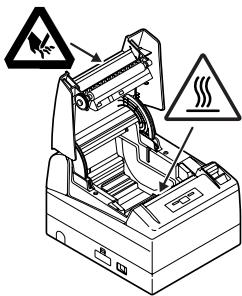
Caution label is attached on the position shown in the following figure. Carefully read the precautions in handling before using the printer.
THESE LABELS INDICATE THE RISK OF ANY INJURY DUE TO "HIGH TEMPERATURE" OF THE PRINT HEAD AND "SAW-TOOTHED EDGE" OF THE MANUAL CUTTER.


CAUTION
■ Do not transport this printer with the paper roll inside.
- Printer failure or breakage may occur.
To prevent possible malfunction or failure observe the following.
- Avoid operating the printer without paper properly loaded.
- Avoid the use of paper not complying with specifications.
- May result in poor print quality.
■ Avoid using torn pieces of paper or spliced with plastic adhesive tapes.
- Avoid forcibly pulling already loaded paper by hand.
■ Avoid wedging the paper into the printer.
- May jam paper. To release, refer to "Removing Jammed Paper" in this manual.
- Avoid using a sharp pointed device to operate panel keys.


■ Be sure to firmly insert the cable plug into its mating socket.
- A cross connection may damage the printer's internal electronics or the host system's hardware.
■ Only use the printer with devices that have designated solenoid specifications for the cash drawer interface connector. - Neglecting this caution may result in malfunction or failure.
To prevent injury and printer failures from worsening, observe the following:
■ Do not touch the printing surface of the thermal head.
- Do not touch any of the moving parts (e.g., paper cutter, gears, active electrical parts) while the printer is working.
In case of trouble do not attempt to repair the printer. Ask Citizen Systems service for repair.
■ Be careful that the printer cover does not entrap your hands or fingers.
■ Be careful with sharp edges on the printer. Do not allow them to injure you or damage property.
- May result in electric shock, burn, or injury.


If the printer emits smoke, an odd smell, or unusual noise while printing, immediately abort the current print session and unplug the printer from the supply outlet.

DAILY MAINTENANCE
Observe the following precautions for daily maintenance.
■ When cleaning the printer, always turn it off and unplug it from the supply outlet.
■ Use a soft, dry cloth for cleaning the surface of the printer case.
■ For severe stains, use a soft cloth slightly dampened with water.
■ Never use organic cleaning solvent such as alcohol, paint thinner, trichloroethylene, benzene, or ketone. Never use a chemically processed cleaning cloth.
■ To remove paper dust, use a soft brush.


CAUTION
- The thermal head is at a dangerously high temperature immediately after printing. Allow it to cool off before launching maintenance work.
1. GENERAL OUTLINE
This product is thermal line printers designed for use with a broad array of terminal equipment including data, POS, and kitchen terminals.
With extensive features, they can be used in a wide range of applications.
1.1 Features
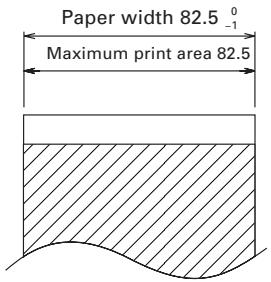
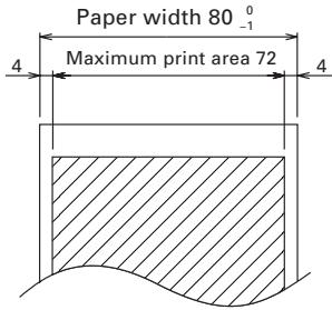
- Versatile roll capacity with ability to use 80 mm, 82.5 mm and 112 mm wide paper rolls.
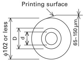
● Can use paper roll with a maximum of 102 mm diameter. - Drop-in paper loading mechanism facilitating easy paper handling and head cleaning.
● High speed (150 mm/s) printing.
● Equipped with USB interface as standard plus a choice of either a serial or parallel interface. - Replaceable interface board.
● High-speed parallel interface (Parallel interface model)
● Built-in cash drawer interface.
● Auto cutter mechanism provided as a standard. - User customization such as memory switch setting are available.
- Page mode
● Registration of user-defined characters and logos into flash memory. - Barcode & 2D Barcode printing is supported.
● 2-color printing is supported (When specified paper is used).
● Error indication is available with LED or buzzer.
[Only CT-S4000L, CT-S4000DCL]
● High speed (132 mm/s) printing.
- Label paper of 58 to 107mm wide in addition to 112-mm wide label paper is usable without step.
[Only CT-S4000L, CT-S4000DCL, CT-S4000M, CT-S4000DCM]
● Paper sensor sensitivity adjustment system by volume is adopted.
1.2 Unpacking
When unpacking the printer, confirm that the following are provided:
● Printer: 1
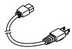
● AC power cord : 1 (for CT-S4000, CT-S4000L, CT-S4000M)
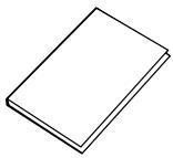
- User's manual (This manual): 1
● Sample paper roll: 1 roll
● Partition: 1
● Screw: 1
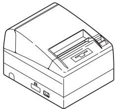
natural_image
Line drawing of a portable electronic device with ports and buttons (no text or symbols)CT-S4000
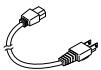
AC power cord
natural_image
Simple line drawing of a closed book or notebook (no text or symbols visible)User's manual (This manual)

Sample paper roll
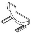
Partition

Screw
1.3 Model Classification
The printer models are classified by the following designation method:
CT - S4000
Power supply
No marking: AC power type (built-in power supply)
DC: DC power supply type
Interface
PA: IEEE1284 & USB
RS: RS-232C & USB
UB: USB only (Option)
RS E - BK -
Label/Black mark
No marking: Standard
L: Label
M: Black mark
Body case color
WH: Cool white
BK: Black
Character set, AC cable,
E: Europe
U: USA
*Description marked "*L" in this manual is the description for CT-S4000L/CT-S4000DCL and that marked "*M" for CT-S4000M/CTS4000DCM. Read this manual after confirming your model in use.
1.4 Basic Specifications
| Item | Specifications | |||||
| Model | CT-S4000 PA/RS/UB, CT-S4000DC PA/RS/UB | |||||
| Print method | Line thermal dot print method | |||||
| Print width *1 | 104 mm/832 dots, 82.5 mm/660 dots, 72 mm/576 dots104 mm/832 dots, 72 mm/576 dots, 50 mm/400 dots | |||||
| Dot density | 8 dots/mm (203 dpi) in horizontal & vertical | |||||
| Print speed | 150 mm/s (Fastest, print density 100 %), 1200 dot lines/sOnly in label mode, 132 mm/s (max), print density level is 88%, and 1056 dot lines/s. | |||||
| Number of print columns *2 | — | Number of print columns (columns) | Dot configuration (Dot) | |||
| Paper widthFont | 112mm | 82.5mm | 80mm | 58mm*L | ||
| Font A | 69 | 55 | 48 | 33 | 12 × 24 | |
| Font B | 92 | 73 | 64 | 44 | 9 × 24 | |
| Font C | 104 | 82 | 72 | 50 | 8 × 16 | |
| Character size *3 | Font A: 1.50 × 3.00 mm Font B: 1.13 × 3.00 mm Font C: 1.00 × 2.00 mm | |||||
| Character type | Alphanumeric, International, PC437 PC850/852/857/858/860/863/864/865/866/WPC1252/Katakana/Thai code 18 | |||||
| User memory | 384 KB (Capable of registering user-defined characters and logos) | |||||
| Types of barcode and 2D barcode | UPC-A/E, JAN (EAN) 13/8 columns, ITF, CODE 39, CODE 128,CODABAR, CODE 93, PDF417, QR Code | |||||
| Line spacing *4 | 4.23 mm (1/6 inch) | |||||
| Paper roll | Thermal paper roll: 112-0mm/82.5-0mm/80-0mm × Maximum φ102 mmPaper thickness: 65-150 μm | |||||
| Interfacing | Serial (RS-232C compliant), Parallel (IEEE 1284 compliant), USB | |||||
| Cash drawer interface | 2 cash drawers are supported. | |||||
| Input buffer | 4K bytes/45 bytes (selectable) in Serial or Parallel interface, 16K bytes in USB interface | |||||
| Supply voltage | AC100 to 240V, 50/60 Hz, 130VA / DC24V, 2.0A | |||||
| Power consumption | Approx. 70W (in normal printing) | |||||
| Weight | Approx. 2.3 Kg for CT-S4000, CT-S4000L, CT-S4000MApprox. 2.0 Kg for CT-S4000DC, CT-S4000DCL, CT-S4000DCM | |||||
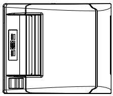
| Outside dimensions | 177 (W) × 213 (D) × 147 (H) mm | |||||
| Operating temperature and humidity | 5 to 45°C, 10 to 90% RH (No condensation) | |||||
| Storage temperature and humidity | -20 to 60°C, 10 to 90% RH (No condensation) | |||||
| Reliability | Print head life: 100 km, 1 × 10⁶ pulses (At normal temperature/humidity with recommended paper used)Auto cutter life:1 million cuts (At normal temperature/humidity with recommended paper used) | |||||
| Safety standard | UL, C-UL, FCC Class A, TÜV-GS, CE Marking | |||||
Notes:
*1: When paper width is 112, 82.5, 80 mm
*2: The number of printable columns are selectable with a Memory Switch.
The number of columns in this table refers to typical model. Printer varies partly in the number of columns depending on printer specifications.
*3: As each character size includes the space inside the character font, actual character looks smaller.
*4: The line spacing is selectable with a command or Memory Switch. When the printer is turned on, it will be slecte with the memory switch.
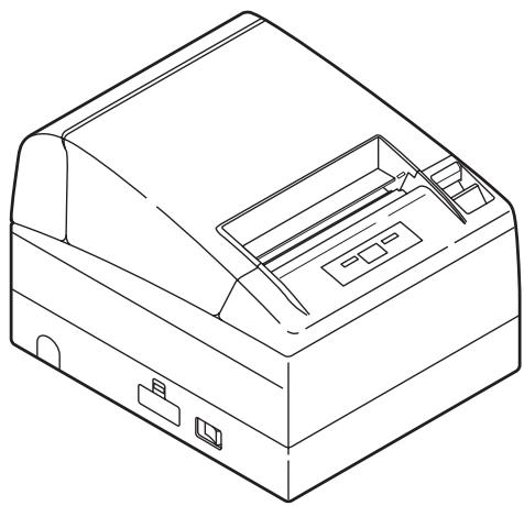
2.1 Printer Appearance
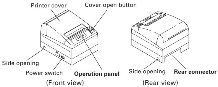
● Printer cover
Paper is loaded under this cover.
- Cover open button
To refill or replace paper, open the printer cover by pulling the cover open button forward.
● Power switch
This switch turns the printer power ON/OFF.
- Side opening
The cables connected to the printer can be routed through this side opening. (Before use, push the small plastic barrier on the cover until it brakes.)
Operation Panel
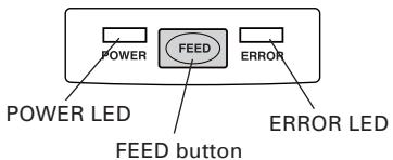
● POWER LED
Illuminated when the printer power is on and off when the printer power is off. May blink or light in a special mode or in case of failure.
● ERROR LED
Illuminated or blinks when paper is empty or in case of failure.
The interval length of blinking represents the type of error.
● FEED button
Pressing this button once causes the paper to feed one line. The longer the button is pressed, the more paper is fed.
Pressing this button causes the paper to feed to the next Black Mark position in Black Mark mode.

See 5.3 Manual Setting of Memory Switch
In case of auto cutter error, press the FEED button after removing the cause of the error.

See 4.6 Error Indication
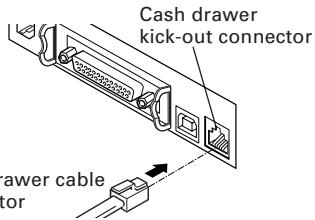
Rear Connectors
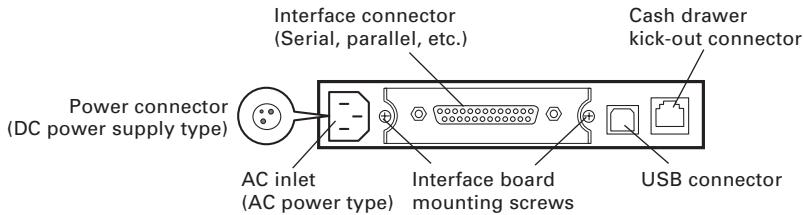
● Interface connector (Serial, parallel, etc.)
Connects to the interface cable. A DIP switch is provided on the serial interface board.
● Cash drawer kick-out connector
Connects to the cable from the cash drawer.
● AC inlet (AC power type)
Connects to the AC power cord.
● Power connector (DC power supply type)
Connects to the cable from DC power source.
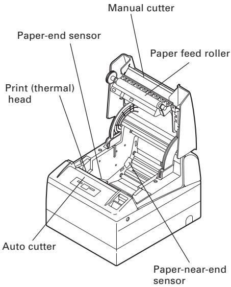
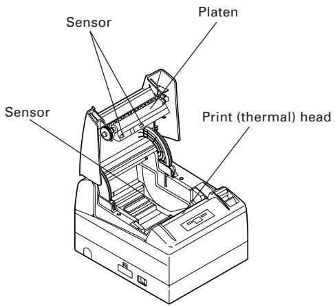
2.2 Printer Cover Inside
● Paper feed roller
Feeds paper as part of print mechanism.
● Paper-near-end sensor
Detects near paper end, change position in accordance with the outer diameter of paper core.
● Auto cutter
Cuts the paper with a command at the end of printing. Cutting method is selectable between partial cut and full cut with a command.
* Factory default of the memory SW4-8 is set to "Partial cut", so that a command will be ignored.
However, full cutting is set for the model supporting label.
- Manual cutter
Tears the paper by hand.
● Print (thermal) head
Prints characters and/or graphic data on thermal paper.
● Paper-end sensor
Stops printing when this sensor detects paper end.
3.1 Connecting the AC Power Cord
- Turn off the printer power switch.
- For AC power type (with built-in power supply), connect the AC power cord to the AC inlet at the back of the printer and plug the AC power cord into the wall outlet.
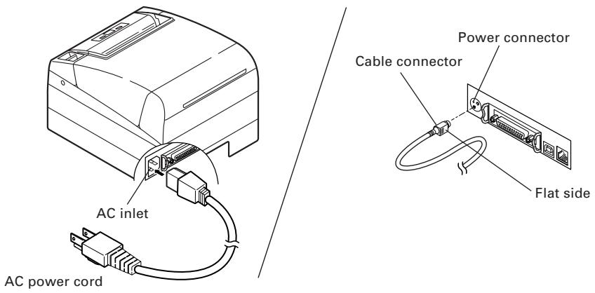
AC power type
(built-in power supply)
DC power supply type

CAUTION!
■ When disconnecting a cable, DO NOT pull out by the cable. Always hold the plug.
■ Always keep the AC power supply away from other noise generating equipment.
■ DO NOT pull the AC power cord. Otherwise fire, electric shock, or power disconnection may result.
If lightning is approaching, unplug the AC power cord from the wall outlet. Otherwise fire or electric shock may result.
- Keep the power cord away from heat generating appliances. Otherwise the shield of power cord may be fused resulting in a fire or electric shock.
If the printer will not be used for a long time, leave it disconnected from its supply outlet.
■ Avoid locating the AC power cord in places which may cause tripping or falling.
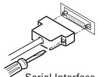
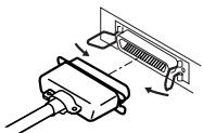
3.2 Connecting Interface Cables
Confirm that the power switch is OFF and connect the interface cable.
Orient the interface cable terminal correctly and insert it into the interface connector.
natural_image
Diagram of a connector with a screwdriver inserted, showing internal structure (no text or symbols)Serial Interface
natural_image
Diagram of a plug assembly with arrows indicating connection to a wall socket (no text or symbols present)Parallel Interface
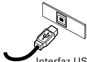
natural_image
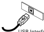
Illustration of an USB interfacial connector with a socket and panel (no text or symbols on the diagram itself)USB Interface

CAUTION!
■ When disconnecting the cable, always hold the connector.
■ Be careful not to insert the USB interface cable into the cash drawer kick-out connector.
For serial interface cable, use the one with the following connection.
25-pin - 25-pin cable
PC
Printer
| Signal | Pin | Pin | Signal | |
| FG | 1 | 1 | FG | |
| TXD | 2 | 2 | TXD | |
| RXD | 3 | 3 | RXD | |
| CTS | 5 | 4 | RTS | |
| DSR | 6 | 6 | DSR | |
| SG | 7 | 7 | SG | |
| DTR | 20 | 20 | DTR |
9-pin - 25-pin cable
PC
Printer
| Signal | Pin | Pin | Signal | |
| RXD | 2 | 2 | TXD | |
| TXD | 3 | 3 | RXD | |
| DTR | 4 | 4 | RTS | |
| SG | 5 | 6 | DSR | |
| DSR | 6 | 7 | SG | |
| CTS | 8 | 20 | DTR |

CAUTION!
Avoid locating the interface cable in places which may cause tripping or falling.
3.3 Connecting the Cash Drawer
- Confirm that the power switch is OFF.
- Confirm the top and bottom of the cash drawer cable connector and insert it into the cash drawer kick-out connector at the back of the printer.
- Screw the cash drawer's ground wire to the body of the printer.
Cash drawer cable connector

CAUTION!
DO NOT connect any other device than the specified cash drawer to the cash drawer kick-out connector. (DO NOT connect a telephone line either.)
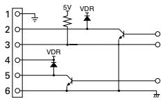
(1) Connector Pin Configuration
| No. | Signal | Function | 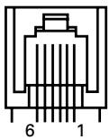 |
| 1 | FG | Frame Ground | |
| 2 | DRAWER 1 | Drawer 1 drive signal | |
| 3 | DRSW | Drawer switch input | |
| 4 | VDR | Drawer drive power supply | |
| 5 | DRAWER 2 | Drawer 2 drive signal | |
| 6 | GND | Common ground on circuits |
Connector used: TM5RJ3-66 (Hirose) or equivalent Applicable connector: TM3P-66P (Hirose) or equivalent
(2) Electrical characteristics
1) Driving voltage: 24 VDC
2) Driving current: Approx. 1A max. (shall not exceed 510 ms.)
3) DRSW signal: Signal levels: "L" = 0 to 0.5 V, "H" = 3 to 5 V
(3) DRSW signal
DRSW signal status can be tested with the DLE+EOT, GS+a, or GS+r command or at pin 34 on the parallel interface port.
(4) Drive Circuit (printer side)

CAUTION!
■ No output is produced while printing.
■ The cash drawers 1 and 2 cannot be driven simultaneously.
A solenoid used for the cash drawer should be of 24 Ω or more. The output current should be kept at 1A or less; otherwise, breakdown or burning could occur.
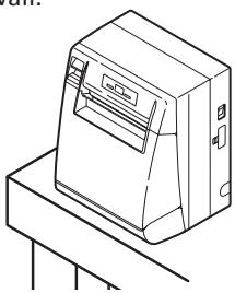
3.4 Installing the Printer
The printer can be installed horizontally, vertically, and on the wall. At the time of shipment, the printer is set for horizontal installation. To install the printer vertically or on the wall, the following adjustments are required.
- Adjustment of paper near-end sensor position (See section 3.7)
- Anti-slip rubber feet (for vertical setting)
- Optional wall-mounting kit (for wall-mounting)
natural_image
Line drawing of a mechanical device with a base and top plate (no text or symbols)Vertical position

CAUTION!
■ When used in vertical position, the printer ejects paper not to fall naturally even with full cutting. Be careful in using the printer built in equipment, etc.
■ Ensure that the wall on which the printer is mounted has enough strength before installation.
■ When using in horizontal setting, avoid cutting full. Otherwise, the cut paper may drop into the cutter and may result in double cutting and narrow pieces of paper. This may cause paper jam.
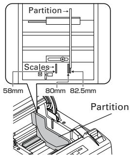
3.5 Partition for Paper Roll
At the time of shipment, this partition is not installed.
- Confirm that the power switch is OFF.
- Open the printer cover.
- Insert the partition into the slot and align it with the scale inside of the printer which meets the width of the paper roll used. When using the 80mm or 82.5mm wide paper roll, set the partition by using the accessory screw. *58 mm is only for label supporting model.
- Change the setting of paper width by reffering to the section 5.2, "Manual Setting of Memory Switch".

CAUTION!
When using 112 paper roll, the partition is not used.
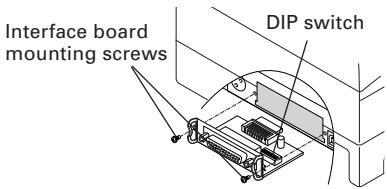
3.6 Setting DIP Switch
The DIP switch is present on the serial interface board.
The function of each switch is as shown below.

CAUTION!
As for the setting of the serial interface, it gives priority to the setting of the memory switch rather than the DIP switch as the factory default.
■ Consult with the dealer where the printer was purchased when the change of the DIP switch setting is necessary.
| Switch No. | Function | ON | OFF | InitialSettings |
| 1 | Communication condition setting method | DIP switch setting | Memory switch setting | OFF |
| 2 | Hand shake | XON/XOFF | DTR/DSR | OFF |
| 3 | Bit length | 7 bits | 8 bits | OFF |
| 4 | Parity check | With parity | None | OFF |
| 5 | Parity selection | Even parity | Odd parity | OFF |
| 6 | Baud rate selection | See Table below. | OFF | |
| 7 | ON | |||
| 8 | INIT | Reset | Invalid | OFF |
Selecting baud rate
| Baud Rate (bps) | Switch No. | |
| 6 | 7 | |
| 2400 | OFF | OFF |
| 4800 | ON | OFF |
| 9600 | OFF | ON |
| 19200 | ON | ON |
38400, 57600 and 115200 bps can also be selected by a command, etc.
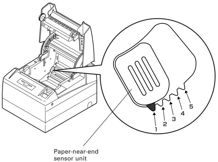
3.7 Adjusting the Paper Near-end Sensor
- Lightly push in the paper near-end sensor unit.
- Move the paper near-end sensor unit to the right and left while keeping to press it. The position to be set varies in accordance with the setting of the printer, horizontal or vertical, or diameter of the paper roll as shown in the following figure.
| Sensor Position | Roll paper diameter at the detection of near-end | Outer core diameter of roll paper used | |
| Horizontal | **1 | 21.0 | 18.0 |
| *2 | 24.5 | 21.5 | |
| 3 | 28.0 | 25.5 | |
| 4 | 31.5 | 28.0 | |
| 5 | 35.0 | 32.0 | |
| Vertical | 5 | 21.0 | 18.0 |
| 4 | 24.5 | 21.5 | |
| 3 | 28.0 | 25.5 | |
| 2 | 31.5 | 28.0 | |
| 1 | 35.0 | 32.0 |
* Factory setting for USA version
** Factory setting for other country version

CAUTION!
■ Paper remaining differs by the type of paper roll used.
■ The external diameter of the paper roll is only for reference.
■ When a paper end error is detected incorrectly during using a paper roll with a honeycomb type core, move the sensor position to the larger number.
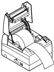
4.1 Setting/Replacing the paper roll
- Pull the cover open button forward.
- Open the printer cover.
- Insert a paper roll with its print area facing down as shown in the figure and pull out the paper end straightforward several cm (or inches) out of the printer.
- Firmly close the printer cover until a click can be heard.

See 5.3 Manual Setting of Memory Switch
natural_image
Technical line drawing of a mechanical device with rollers and clamps (no text or symbols)
CAUTION!
■ Always use the specified types of paper roll.
■ Confirm that the paper roll is set correctly.
■ When the paper is skewed and not extended straightforward from under the printer cover, open the printer cover and adjust the paper correctly.
■ When the printer cover is opened after setting the paper, be sure to pull the paper straightforward several cm (or inches) out of the printer, and then close the printer cover.
■ When closing the printer cover, press on the center part of the cover to close it firmly.
■ When setting paper, be careful not to have your finger injured by the manual cutter or paper edge.
In the case of selecting "Valid" with memory SW4-3, the paper is fed and cut automatically when the printer cover is closed.

WARNING
When opening the printer cover, DO NOT touch the print head or cutter blade. Otherwise, burning or injury of hand may result.
4.2 Removing Jammed Paper
- Turn the printer power off.
- Open the printer cover.
If the cutter blade remains protruded with paper jammed, do not force the printer cover to open. Referring to the section 4.7, restore the blade to the normal position and then open the cover. - Remove the jammed paper including any remaining paper shreds.
- Turn on the printer. The auto cutter mechanism is initialized and the alarm is cleared.

CAUTION!
If the cutter blade remains protruded with paper jammed, DO NOT open the printer cover foribly and try to turn OFF and ON the printer power. If the cutter blade cannot be restored, refer to the section 4.7.
■ The print head is hot immediately after printing. DO NOT touch it with your hand. DO NOT touch the heating element of the head with a bare hand or metal object either.
4.3 Periodic cleaning
If the print head or platen is dirty, clear printing is not available or fault may occur. If paper dust or the like is present on the sensor protection sheet, label paper or blackmark paper may not be detected correctly. Periodic cleaning in accordance with the following procedure is recommended.
- Turn the printer power off.
- Open the printer cover.
- Wait several minutes. Wipe off any debris on the heating element of the head using a cotton swab soaked in ethyl alcohol. Just after printing, high temperature remains in the print (thermal) head. Be careful not to touch it by hand.
- Moisten the tip of the cotton swab with water and wipe the dirt on the surface of the sensor protection sheet. Avoid using solvent such as alcohol. Use of it may result in smoky sensor protection sheet.

CAUTION!
■ Do not touch the surface of the heating element of the print head by bare hand or metal.
■ Wipe the dust off the surface of the platen periodically with a cotton swab moistened with ethyl alcohol. Especially, when full cutting is used for label paper, paper dust may adhere on the platen depending on the property of liner sheet, roll paper diameter, environmental condition of using the printer, etc.
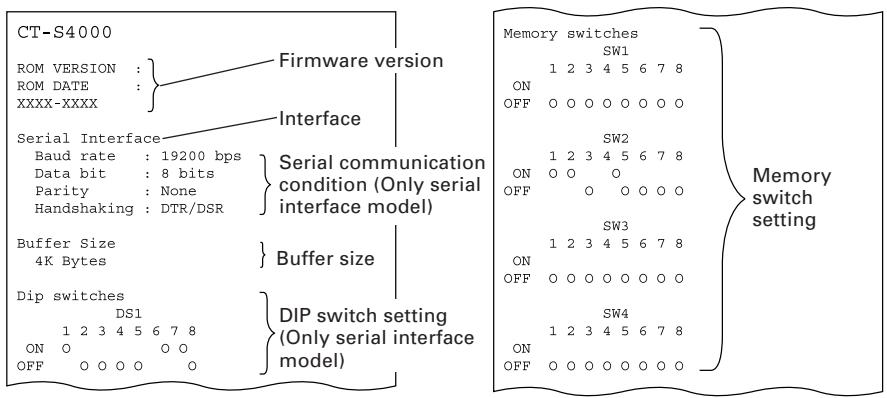
4.4 Self-printing
Insert paper into the printer. With the FEED button pressed and held, turn the printer power on, keep the FEED button held for about 1 second, and then release the FEED button. The printer starts self-printing. The printer prints model name, version, DIP switch setting, memory switch setting, and built-in fonts.
4.5 Hexadecimal Dump Printing
This function is to print all received data in hexadecimal numbers. If problems such as missing data, data duplication, etc. should occur, this function allows checking whether or not the printer is receiving data correctly.
Load the paper into the printer and keep the printer cover open. With the FEED button pressed and held, turn the printer power on and then close the printer cover. The printer prints "HEX dump print mode" followed by the received data printed in hexadecimal numbers and some characters.

CAUTION!
■ The printer prints “.” if there is no characters corresponding to data.
■ During hexadecimal dump, functions except some command will be disabled.
■ If print data DOES NOT cover a line, press the FEED button to print the line.
When you press the FEED button three times consecutively, or you turn the printer power off, or the printer receives a reset signal from the interface, the hexadecimal dump printing is terminated.
Print example
| HEX | DUMP | MODE | |||||||||
| 1B | 21 | 00 | 1B | 20 | 04 | 41 | 42 | 43 | 44 | . ! . . | .ABCD |
| 45 | 46 | 47 | 48 | 49 | 4A | 4B | 4C | 4D | 4E | EFGHIJKLMN | |
| 4F | 50 | 0D | 0A | 31 | 32 | 33 | 0D | 0A | OP..123.. | ||
4.6 Error Indication
● Paper end
Paper out is detected in two steps: paper near-end and paper end. ERROR LED will light when the paper is empty. If paper end is detected, refill the paper. If the printer cover is open, a paper-end is detected.
● Printer cover open
During printing, do not open the printer cover. If you open the printer cover accidentally, the ERROR LED blinks. Check the paper, pull the paper straightforward several cm (or inches) out of the printer, and then close the printer cover. Printing resumes automatically. Sending a command to resume printing may be required depending on the memory switch setting.
● Cutter lock
If the cutter blade stops operating due to paper jam or the like, the ERROR LED blinks. Remove the cause of the trouble and press the FEED button. If the blade still does not move and the printer cover cannot be opened, refer to the section 4.7.
● Thermal head overheat
When you print dense characters or dark image, the head temperature rises. If the head temperature exceeds a specified level, the printer stops printing operation and waits till the head temperature is lowered. During waiting, the ERROR LED blinks. When the head temperature is lowered, printing resumes automatically.
● Paper jam error
If paper feeding is not normal and paper jam occurs in the platen, etc., printing and line feed operation stop and ERROR LED blinks.
● Power switch operation error
If you turn power on again just after powering off, an error may occur.
Before turning power on again, wait till POWER LED goes off completely after powering off.
● Black Mark detection error (in Black Mark mode)
When Black Mark cannot be detected even if a certain amount of paper feed is carried out for Black mark detection, a Black Mark detection error occurs. If black detection continues more than the specified period, a No Paper condition is assumed and the same error as No Paper is indicated.
● Waiting for paper (label) cutting
If the "GS+FF" command is executed under the condition that auto cutter operation is disabled (memory switch 2-2 is OFF), label paper is ejected and ERROR LED blinks. When the FEED switch is pressed under this circumstance, paper returns to the starting position of printing and ERROR LED goes off.
● Paper (label) detection error
If detection is not available even with paper feeding of given amount for detecting space between labels or label paper, ERROR LED blinks. In this case, adjust the sensor in the paper sensor adjustment mode. If no detection occurs even after the sensor adjustment, replace the label paper. If replacing label paper is not effective for detection, the sensor, etc. may be faulty (degraded). Contact the service representative.
Lighting and blinking status of each error including the above is shown below.
| Status | POWER LED | ERROR LED | Buzzer |
| Paper-end | Lights | Lights |  |
| Paper near-end | Lights | Lights | — |
| Printer cover open | Lights | Lights | — |
| Printer cover open error *1 | Lights |  |  |
| Cutter lock error | Lights |  |  |
| Head overheat error | Lights |  | — |
| Paper jam error | Lights |  |  |
| Memory check error |  | Lights | — |
| Low voltage error | Lights |  |  |
| High voltage error or Power switch operation error | Lights |  _ _ |  |
| Macro execution wait *2 | Lights |  |  |
| Black Mark detection error | OFF |  |  |
| Waiting for paper (label) cutting*L, *M | OFF |  |  |
| Paper (label) detection error*L, *M | OFF |  |  |
*1: When the printer is printing.
*2: The ERROR LED may blink even in the execution of macro function.
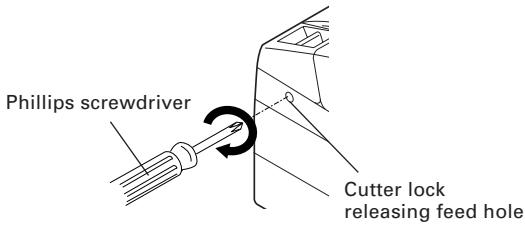
4.7 When the Paper Cover Cannot Be Opened
If the cutter blade remains protruded due to paper jam or for any abnormality, opening the paper cover may be disabled. In this case, do not open the paper cover forcibly. Insert a Phillips screwdriver (size #1) into the cutter lock releasing feed hole and turn it in the direction of arrow (clockwise).
When you find that both ends of the blade reached the lowest position, stop turning the screwdriver. Open the cover and follow the procedure of removing jam or other cause of trouble.
5.1 External Views and Dimensions
natural_image
Technical line drawing of a rectangular device with internal compartments and a central control panel (no text or symbols)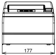
natural_image
Technical line drawing of a rectangular electronic device with a top panel and base, labeled with dimension 177 (no text or symbols on the device itself)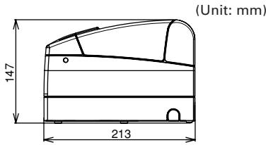
5.2 Printing Paper
Use the print paper shown in the following table or the paper with equivalent quality.
| Paper Type | Product Name |
| Recommended thermal paper roll | F230AA, P220AG, HP220A, HP220AB-1, P220AB, P220AE-1, PB670 (Red/Black), PB770 (Blue/Black) from Mitsubishi Paper TF50KS-E2D from Nippon Paper PD150R, PD160R from Ohji Paper |
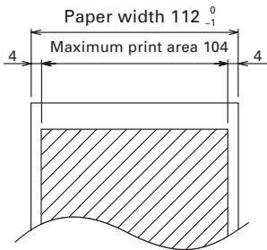
(Unit: mm)
| Paper thickness (μm)* | 65-75 | 75-150 |
| Core inner diameter d (mm) | 12 | 25.4 |
| Core outer diameter D (mm) | 18 | 32 |
*Thickness of label paper is the total of the thickness of "liner sheet" and "label".

CAUTION!
DO NOT use the following type of paper roll.
■ Paper with folds.
■ Paper with bent corners.
■ Paper pasted or glued to the core.
■ In-wound paper roll (print side in).
When using "label paper" with CT-S4000L and CT-S4000DCL, refer to the following. Use the following paper or the equivalent paper.
| Paper type | Product name |
| Recommended thermal label paper | 150LA-1 from Ricoh, GG40/P22/G6B from Ojitac, HD75 from Nippon Paper |
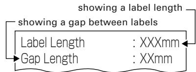
a) Label paper *L
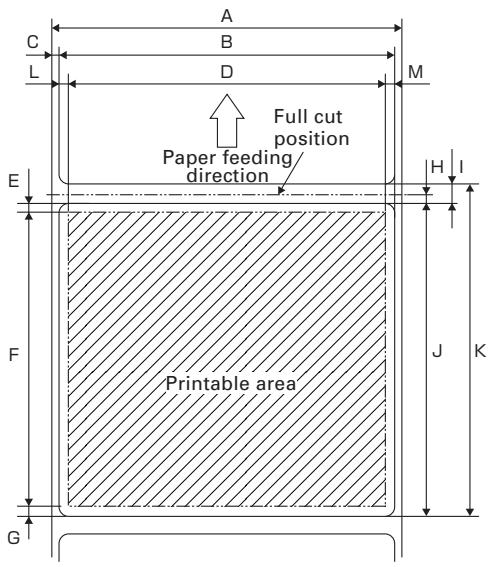
Unit: mm
| Mark | Item | Dimensions |
| A | Liner width | 58 to 112 _-1^0 |
| B | Label width | 54 to 108 ± 0.5 |
| C | Left edge of label | 2 + 0.5 |
| D | Print width | 50 to 104 |
| E | Top margin | 2 ± 1 |
| F | Print length | 21 to 296 |
| G | Bottom margin | 2 ± 1 |
| H | Cut position between labels | 1/2 x (Size I) |
| I | Gap between labels | 4 to 30 |
| J | Label length | 25 to 300 |
| K | Label pitch | I+J |
| L | Left margin | 2 ± 1 |
| M | Right margin | 2 ± 1 |

CAUTION!
Pay attention to the following when using Auto Cutter. Otherwise, a cutter lock or a cutter failure may occur.
■ Set the cut length of paper to 25 mm or more.
■ When using label paper, cut the gap between labels (liner sheet). Do not cut the label paper (tack paper).
■ Adusting the paper sensor must be carried when the type of liner is changed.
Label paper cannot be used with the model supporting blackmark (CT-S4000M/CT-S4000DCM).
b) Black mark paper (BM paper)
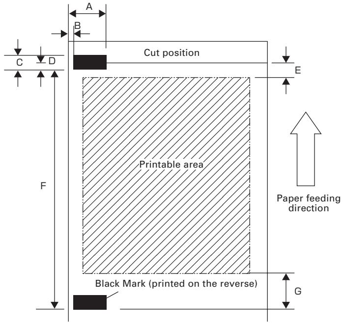
Unit: mm
| Mark | Item | Dimensions |
| A | Right edge of black mark | 15 or more |
| B | Left edge of black mark | 0 to 1.5 |
| C | Black mark height | 5 |
| D | Cut position in black mark | 2.5 |
| E | Top margin | 6.5 / 12 |
| F | Black mark pitch | 30 to 300 |
| G | Bottom margin | 9 |
* In the case of the operation that the printer cuts the paper, the top margin will be changed by the setting of the memory switch 4-8. It is 6.5mm at 0 (OFF) and 12mm at 1(ON).
* In the case of the operation that the printer does not cut the paper, the top margin is 6.5mm.

CAUTION!
■ PCS value of black mark must be 0.9 or more.
■ When using the black mark paper, consider the margin of +/- 2 mm for the print position against the standard position and +/- 5 mm for print length.
■ Refer to the above drawing for the printable area and have enough margins specified in the marks E and G. If the print data size is out of the printable area, the printer should skip to next page.
5.3 Manual Setting of Memory Switch
Memory switches can be set manually or by a command.
For manual setting, refer to the next page.
The function of each memory switch is shown in the following table.
(The white-on-black characters factory setting.)
| Switch No. | Setting | 0 (OFF) | 1 (ON) |
| Memory SW1-1 | Power ON Info | Valid | Not send |
| SW1-2 | Buffer Size | 4k bytes | 45 bytes |
| SW1-3 | Busy Condition | Full/Err | Full |
| SW1-4 | Receive Error | Print (?) | No Print |
| SW1-5 | CR mode | Ignored | LF |
| SW1-6 | Reserved | Fixed | - |
| SW1-7 | DSR Signal | Invalid | Valid |
| SW1-8 | Init Signal | Invalid | Valid |
| Memory SW2-1 | Reserved | - | Fixed |
| SW2-2 | Auto Cutter | Invalid | Valid |
| SW2-3 | Spool Print | Invalid | Valid |
| SW2-4 | Full Col Print | LineFeed | WaitData |
| SW2-5 | Resume aft PE | Next | Top |
| SW2-6 | Reserved | Fixed | - |
| SW2-7 | Reserved | Fixed | - |
| SW2-8 | PNE Sensor | Valid | Invalid |
| Memory SW3-1 | Resum Ctr Err | Valid | Invalid |
| SW3-2 | Reserved | Fixed | - |
| SW3-3 | Parallel 31 Pin | Valid | Invalid |
| SW3-4 | Reserved | Fixed | - |
| SW3-5 | Reserved | Fixed | - |
| SW3-6 | Reserved | Fixed | - |
| SW3-7 | CBM1000 Mode | Invalid | Valid |
| SW3-8 | Resum Open Err | Close | Command |
| Memory SW4-1 *M | P. Length Set | Auto Measure | Command |
| SW4-2 *M | Power on TOF | Invalid | Valid |
| SW4-3 | Feed&Cut at TOF | Invalid | Valid |
| SW4-4 *L | Paper Select *1 | Thermal Roll | BM.P / Lbl.P *4 |
| SW4-5 *L | Position detect *2 | Black Mark | Label |
| SW4-4 *M | Paper Select *1 | Thermal Roll | BM.P |
| SW4-5 *M | Position detect *2 | Black Mark | - |
| SW4-6 | Reserved | Fixed | - |
| SW4-7 | Reserved | Fixed | - |
| SW4-8 *3 | Prtial Only | Invalid | Valid |
Notes:
*1: The factory setting of "Paper Select" will be different, depending on the model classification.
*2: In the case of selecting the thermal roll with the SW4-4, the SW4-5 will not be available. The SW4-5 will be set to "Black Mark" status for the Black Mark version printer.
*3: In the label mode (with memory switches SW4-4 and SW4-5 set to ON), full cutting is used for paper regardless of the setting of memory switch SW4-8.
*4: When printing on label paper, printing columns of 660 dots is not usable.
Memory switch SW2-8 is not usable with label paper.
| Switch No. | Setting | 0 (OFF) | 1 (ON) |
| Memory SW5-1 | Buzzer | Valid | Invalid |
| SW5-2 | Line Pitch | 360 | 406 |
| SW5-3 | USB Mode | Virtual COM | Printer Class |
| SW5-4 | Reserved | Fixed | - |
| SW5-5 | Reserved | nvalid | - |
| SW5-6 | Reserved | Fixed | - |
| SW5-7 | Reserved | Fixed | - |
| SW5-8 | Reserved | Fixed | - |
| Switch No. | Setting | Default | Set Values |
| Memory SW7-1 | Baud Rate | 9600 bps | 1200 bps, 2400 bps, 4800 bps, 9600 bps, 19200 bps, 38400 bps, 57600 bps, 115200 bps |
| SW7-2 | Data Length | 8Bits | 7Bits, 8Bits |
| SW7-3 | Stop Bit | 1Bit | 1Bit, 2Bits |
| SW7-4 | Parity | NONE | NONE, EVEN, ODD |
| SW7-5 | Flow Control | DTR/DSR | DTR/DSR, XON/XOFF |
| SW7-6 | DMA Control | Valid | Valid, Invalid |
| SW7-7 | VCom Protocol | PC Setting | PC Setting, DTR/DSR, XON/XOFF |
| Memory SW8-1 | Print Width | 832dots | 832dots(69 col.), 720dots(60col.), 660dots(55col), 576dots(48col.), 512dots(42col) |
| SW8-2 | Paper Type | 1 Color Normal | 1 Color Normal, 2 Color Normal |
| Memory SW9-1 | Code Page | PC437 | PC437/Katakana/PC850,858/PC860/PC863/PC865/PC852/PC866/PC857/WPC1252/PC864/Thai Code 18 |
| Memory SW9-2 | Int'Char Set | USA | USA, France, Germany, England, Denmark, Sweden, Italy, Spain, Japan, Norway, Denmark 2, Spain 2, Latin America, Korea Croatia, China |
| Memory SW9-3* | Kanji | OFF | ON, OFF |
| SW9-4* | JIS/Shift JIS | JIS | JIS, Shift JIS |
| Memory SW10-1 | Print Density | 100% | 70%, 75%, 80%, 85%, 90%, 95%, 100%, 105%, 110%, 115%, 120%, 125%, 130%, 135%, 140% |
| SW10-2 | Print Speed | Level 9 | Level 1, Level 2, Level 3, Level 4, Level 5, Level 6, Level 7, Level 8, Level 9 |
| SW10-3 | ACK Timing | Before Busy | Before Busy, Same Period, After Busy |
| SW10-4 | NV User | 192K bytes | 1K bytes, 64K bytes, 128K bytes, 192K bytes |
| SW10-5 | NV Graphic | 384K bytes | 0 byte, 64K bytes, 128K bytes, 192K bytes, 256K bytes, 320K bytes, 384K bytes |
* In this printer, Memory Switches 9-3 and 9-4 are not usable.
Manual Setting of Memory Switch (Memory SW)
The memory switch can be selected, changed, or written by the combination of three actions: pressing the FEED button, pressing and holding the FEED button, and opening or closing the printer cover.
- Entering memory switch setting mode.
Set paper in the printer and keep the printer cover open. With the FEED button pressed and held, turn the printer power on, and then press the FEED button twice. Close the cover. If the current settings of the memory switch etc. are printed, the printer is now in the memory switch setting mode.
Memory SW (1) 00000000
0: OFF state
1: ON state
(No indication for 0/1 with memory switch SW7 through SW10)
- Selecting memory switch (MEMORY SWITCH SELECT MODE)
When the FEED button is pressed short (*1), printing occurs in the order of "Memory SW1" → "Memory SW2" → "Memory SW3" → ...... "Memory SW10" → "Save To Memory" → "Memory SW1" → ...... repeatedly. When the memory switch you want to change is reached, press and hold the FEED button (for more than 2 seconds).
- Selecting each switch item
2-16 items are provided for setting in each switch. By pressing and holding the FEED button long (*2), the printer goes to the next item and prints the current setting of the item. Repeat pressing and holding until the item you want to change is reached.
Power ON Info (Valid)
OFF state: ERROR LED OFF
ON state: ERROR LED ON
(With memory switch SW7 through SW10, ERROR LED goes on only at the factory setting.)
- Changing the setting
When the item you want to change is printed, press the FEED button short (*1). The changed set value is printed. (When the change of the set value is repeated, the original set value is recovered). When you press the FEED button long (*2), the set value is accepted and then the printer goes to the next setting item.
- Returning to the MEMORY SWITCH SELECT MODE (the above Item 2)
When the setting of the desired content is completed, open the printer cover and then close the printer cover. This allows the printer to print the setting of the changed memory switch.
- Saving the setting and exiting the memory switch setting mode
Press the FEED button short (*1) to move to "Save To Memory". Then press and hold the FEED button. The printer prints the contents of new setting and exits the memory switch setting mode to return to the normal standby state.
* Unless saving the setting is executed, the changed setting cannot be enabled.
- Initializing the memory switch
When you want to return the memory switch setting to the initial state, go to "Save To Memory" in the above procedure. Here, open the printer cover and press and hold the FEED button till buzzer sounds. This allows the printer to return to the initial state.
* All the memory switches settings are returned to the factory set values.
*1: Press for less than 2 seconds *2: Press for more than 2 seconds
5.4 Selecting Paper Type \*L, \*M
Paper type selection is available by the combination of memory switches SW4-4 and SW4-5 by the used of "Memory Switch Select Mode". In addition, the following procedure is available.
1 Enter Selecting Paper Type mode.
1) Open the printer cover and remove paper. Pressing and holding the FEED button, turn the printer power ON. The POWER LED starts blinking.
2) Release the FEED button and then close the printer cover. Buzzer sounds and the paper type currently set is indicated by the LED on the operation panel.
2 Select Paper Type.
Press the FEED button to match the paper type loaded to the LED indications in the table below. (Refer to the table below.)
| POWER LED | ERROR LED | |
| Green lit | (OFF) | |
| (OFF) | Red lit | |
| Green lit | Red lit |
3 Save the selected Paper Type to the Printer.
Open and close the printer cover. By this operation, selected paper type is stored in the printer memory and the Selecting Paper Type mode is terminated.
Since then, "P.Length Set" of Memory switch 4-1 becomes disable.
When closing the printer cover during the setting a Black Mark paper or label paper in the printer, paper length is measured, and the result will be printed out.
* If Paper Detection error occurs at the measurement of paper length, the printer automatically enters Adjusting Paper Sensor mode. Adjust the sensor in accordance with "5-5 Adjusting Paper Sensor".
5.5 Adjusting Paper Sensor *L , *M
Before using Black Mark paper (BM paper) or label, adjust the Paper sensor. First, hold the lever at the upper end of the sensor adjustment control cover located at the left of the Power switch and press the lever down and toward the front to remove the cover from the printer.
As shown below, the most left one is a label paper sensor adjuster, the next is Black Mark paper sensor adjuster, and the right one is a level indicator LED. Adjust them in the following procedure.
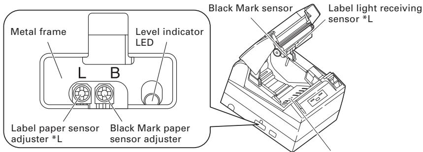
Label light emitting sensor *L
1 Enter Adjusting Paper Sensor mode.
Open the printer cover, remove paper, and then set the printer power switch to ON. Here, POWER LED and ERROR LED go on with the buzzer sound. Then close the printer cover while pressing the FEED button. The ERROR LED starts blinking with the buzzer sound.
2 Set Paper to be adjusted to the Printer.
This printer has three types of built-in paper sensors.
In case of label, set it so that label is positioned on the label light receiving sensor and label light emitting sensor. In case of Black Mark paper, set it so that the printable portion (other than black mark) is positioned on the Black Mark sensor. With this state kept, closing the printer cover causes ERROR LED to blink with the buzzer sound.
3 Adjust Paper Sensor.
Turn the corresponding adjuster counterclockwise by using a tapered flat screwdriver. Set the adjuster at the position where LED begins to change from orange to green.

Turning the adjuster counterclockwise
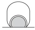
Green

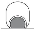
Orange


Red
* While turning the adjuster by the screwdriver, do not let the part of the screwdriver touch the metal frame. Otherwise proper LED light color will not be displayed while touching.
4 Perform Paper Measuring operation
When the FEED button is pressed, label is fed and paper measuring is carried. If the FEED button is presed during the paper measuring, the result will be printed out as follows, and the printer memory switch will be initialized.
* The measuring result is a reference value
< Example of label measuring result*L >
< Example of black mark paper measuring result *M>

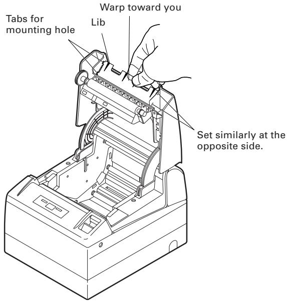
5.6 Full cutting label paper * L
When full-cutting the label paper with the printer installed horizontally, Be sure that the guide plate is mounted on the paper exit of the printer cover.
(This guide plate was set to the printer at the time of factory shipment.)
The Guide Plate prevents cut paper from dropping in the printer.

CAUTION!
■ If about 10 sheets of cut paper accumulate on the paper exit, remove the paper.
- Stacking of 10 or papers, paper jam may occur.
■ Remove the guide plate in other than full-cutting label paper with the printer set horizontally.
- The manual cutter cannot be used when the guide plate is mounted.
- Short label paper with the printer set vertically may be hard to exit.
●Mounting and Dismounting Guide Plate
- Mounting
With the printer cover kept open, insert the tabs of the guide plate to the two mounting holes (either right or left hole) located at the inside of the cover front. Set the guide plate with its lib facing toward you.
Then, with the guide plate warping toward you, insert the tabs to the two mounting holes at the opposite side of the cover.
- Dismounting
With the printer cover kept open, pull the center portion of the guide plate toward you to remove the guide plate.
FRANÇAIS
PRÉCAUTIONS GÉNÉRALES
CITIZEN is a registered trade mark of Citizen Holdings Co., Japan
Company names and product names in this manual are trademarks or registered trademarks of relevant companies.
Copyright© 2008 by CITIZEN SYSTEMS JAPAN CO., LTD.
PRÉCAUTIONS DE SÉCURITÉ ... QUI DEVRAIENT ÊTRE OBSERVÉES RIGOUREUSEMENT

ATTENTION
natural_image
Line drawing of a portable electronic device with ports and buttons (no text or symbols)CT-S4000

Cordon secteur.

natural_image
Simple line drawing of a closed book or notebook (no text or symbols visible)| PC | Imprimante | ||
| Signal | Pin | Pin | Signal |
| FG | 1 | 1 | FG |
| TXD | 2 | 2 | TXD |
| RXD | 3 | 3 | RXD |
| CTS | 5 | 4 | RTS |
| DSR | 6 | 6 | DSR |
| SG | 7 | 7 | SG |
| DTR | 20 | 20 | DTR |
Câble 9 broches - 25 broches
| PC | Imprimante | ||
| Signal | Pin | Pin | Signal |
| RXD | 2 | 2 | TXD |
| TXD | 3 | 3 | RXD |
| DTR | 4 | 4 | RTS |
| SG | 5 | 6 | DSR |
| DSR | 6 | 7 | SG |
| CTS | 8 | 20 | DTR |

ATTENTION!
natural_image
Line drawing of a mechanical device with a rectangular base and a vertical slot, no text or symbols present.Position verticale

ATTENTION!
natural_image
Technical line drawing of a mechanical device with rollers and clamps (no text or symbols)
natural_image
Top-down line drawing of a rectangular device with internal compartments and a control panel (no text or symbols)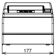
natural_image
Technical line drawing of a rectangular electronic device with a 177-unit base and top panel (no text or symbols)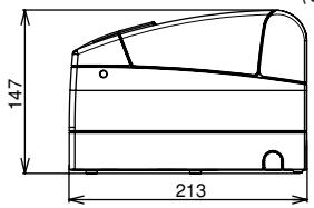
(Unité: mm)
| No. commutateur | Réglage | 0 (OFF) | 1 (ON) |
| Memory SW1-1 | Power ON Info | Valid | Not send |
| SW1-2 | Buffer Size | 4k bytes | 45 bytes |
| SW1-3 | Busy Condition | Full/Err | Full |
| SW1-4 | Receive Error | Print "7" | No Print |
| SW1-5 | CR mode | Ignored | LF |
| SW1-6 | Reserved | Fixed | - |
| SW1-7 | DSR Signal | Invalid | Valid |
| SW1-8 | Init Signal | Invalid | Valid |
| Memory SW2-1 | Reserved | - | Fixed |
| SW2-2 | Auto Cutter | Invalid | Valid |
| SW2-3 | Spool Print | Invalid | Valid |
| SW2-4 | Full Col Print | LineFeed | WaitData |
| SW2-5 | Resume aft PE | Next | Top |
| SW2-6 | Reserved | Fixed | - |
| SW2-7 | Reserved | Fixed | - |
| SW2-8 | PNE Sensor | Valid | Invalid |
| Memory SW3-1 | Resum Ctr Err | Valid | Invalid |
| SW3-2 | Reserved | Fixed | - |
| SW3-3 | Parallel 31 Pin | Valid | Invalid |
| SW3-4 | Reserved | Fixed | - |
| SW3-5 | Reserved | Fixed | - |
| SW3-6 | Reserved | Fixed | - |
| SW3-7 | CBM1000 Mode | Invalid | Valid |
| SW3-8 | Resum Open Err | Close | Command |
| Memory SW4-1 *M | P. Length Set | Auto Measure | Command |
| SW4-2 *M | Power on TOF | Invalid | Valid |
| SW4-3 | Feed&Cut at TOF | Invalid | Valid |
| SW4-4 *L | Paper Select *1 | Thermal Roll | BM.P / Lbl.P *4 |
| SW4-5 *L | Position detect *2 | Black Mark | Label |
| SW4-4 *M | Paper Select *1 | Thermal Roll | BM.P |
| SW4-5 *M | Position detect *2 | Black Mark | - |
| SW4-6 | Reserved | Fixed | - |
| SW4-7 | Reserved | Fixed | - |
| SW4-8 *3 | Prtial Only | Invalid | Valid |
Notes:
| No. commutateur | Réglage | 0 (OFF) | 1 (ON) |
| Memory SW5-1 | Buzzer | Valid | Invalid |
| SW5-2 | Line Pitch | 360 | 406 |
| SW5-3 | USB Mode | Virtual COM | Printer Class |
| SW5-4 | Reserved | Fixed | - |
| SW5-5 | Reserved | nvalid | - |
| SW5-6 | Reserved | Fixed | - |
| SW5-7 | Reserved | Fixed | - |
| SW5-8 | Reserved | Fixed | - |
| No. commutateur | Réglage | Réglage par défaut | Valeurs de réglage |
| Memory SW7-1 | Baud Rate | 9600 bps | 1200 bps, 2400 bps, 4800 bps, 9600 bps, 19200 bps, 38400 bps, 57600 bps, 115200 bps |
| SW7-2 | Data Length | 8Bits | 7Bits, 8Bits |
| SW7-3 | Stop Bit | 1Bit | 1Bit, 2Bits |
| SW7-4 | Parity | NONE | NONE, EVEN, ODD |
| SW7-5 | Flow Control | DTR/DSR | DTR/DSR, XON/XOFF |
| SW7-6 | DMA Control | Valid | Valid, Invalid |
| SW7-7 | VCom Protocol | PC Setting | PC Setting, DTR/DSR, XON/XOFF |
| Memory SW8-1 | Print Width | 832dots | 832dots(69 col.), 720dots(60col.), 660dots(55col), 576dots(48col.), 512dots(42col) |
| SW8-2 | Paper Type | 1 Color Normal | 1 Color Normal, 2 Color Normal |
| Memory SW9-1 | Code Page | PC437 | PC437/Katakana/PC850,858/PC860/PC863/PC865/PC852/PC866/PC857/WPC1252/PC864/Thai Code 18 |
| Memory SW9-2 | Int'Char Set | USA | USA, France, Germany, England, Denmark, Sweden, Italy, Spain, Japan, Norway, Denmark 2, Spain 2, Latin America, Korea Croatia, China |
| Memory SW9-3* | Kanji | OFF | ON, OFF |
| SW9-4* | JIS/Shift JIS | JIS | JIS, Shift JIS |
| Memory SW10-1 | Print Density | 100% | 70%, 75%, 80%, 85%, 90%, 95%, 100%, 105%, 110%, 115%, 120%, 125%, 130%, 135%, 140% |
| SW10-2 | Print Speed | Level 9 | Level 1, Level 2, Level 3, Level 4, Level 5, Level 6, Level 7, Level 8, Level 9 |
| SW10-3 | ACK Timing | Before Busy | Before Busy, Same Period, After Busy |
| SW10-4 | NV User | 192K bytes | 1K bytes, 64K bytes, 128K bytes, 192K bytes |
| SW10-5 | NV Graphic | 384K bytes | 0 byte, 64K bytes, 128K bytes, 192K bytes, 256K bytes, 320K bytes, 384K bytes |
- Selecting each switch item
Power ON notify setting (Valid)
CITIZEN is a registered trade mark of Citizen Holdings Co., Japan
Company names and product names in this manual are trademarks or registered trademarks of relevant companies.
Copyright© 2008 by CITIZEN SYSTEMS JAPAN CO., LTD.

VORSICHT
[Nur CT-S4000L, CT-S4000DCL]
[Nur CT-S4000L, CT-S4000DCL, CT-S4000M, CT-S4000DCM]
natural_image
Line drawing of a portable electronic device with ports and buttons (no text or symbols)CT-S4000
Netzkabel
natural_image
Simple line drawing of a closed book or notebook (no text or symbols visible)natural_image
Technical illustration of a connector with a screwdriver inserted, showing internal components (no text or symbols)natural_image
Diagram of a mechanical component with arrows indicating assembly or connection (no text or symbols present)natural_image
Illustration of an USB switch connected to a wall-mounted socket (no text or symbols)USB-Schnittstelle

VORSICHT!
| Signal | Pin | Pin | Signal | |
| FG | 1 | 1 | FG | |
| TXD | 2 | 2 | TXD | |
| RXD | 3 | 3 | RXD | |
| CTS | 5 | 4 | RTS | |
| DSR | 6 | 6 | DSR | |
| SG | 7 | 7 | SG | |
| DTR | 20 | 20 | DTR |
9-Pin - 25-Pin-Kabel
PC
Drucker
| Signal | Pin | Pin | Signal | |
| RXD | 2 | 2 | TXD | |
| TXD | 3 | 3 | RXD | |
| DTR | 4 | 4 | RTS | |
| SG | 5 | 6 | DSR | |
| DSR | 6 | 7 | SG | |
| CTS | 8 | 20 | DTR |

VORSICHT!
natural_image
Line drawing of a mechanical device with a rectangular base and a vertical panel (no text or symbols)Vertikale Position
Papiermengen-Sensor
natural_image
Line drawing of a mechanical device with rollers and clamps (no text or symbols)
natural_image
Technical line drawing of a rectangular device with internal components and ventilation slots (no text or symbols)
natural_image
Technical line drawing of a mechanical device with dimension标注 (no text or symbols)
5.2 Druckpapier
| Switch-Nr. | Einstellung | 0 (AUS) | 1 (AN) |
| Memory SW1-1 | Power ON Info | Valid | Not send |
| SW1-2 | Buffer Size | 4k bytes | 45 bytes |
| SW1-3 | Busy Condition | Full/Err | Full |
| SW1-4 | Receive Error | Print (?) | No Print |
| SW1-5 | CR mode | Ignored | LF |
| SW1-6 | Reserved | Fixed | - |
| SW1-7 | DSR Signal | Invalid | Valid |
| SW1-8 | Init Signal | Invalid | Valid |
| Memory SW2-1 | Reserved | - | Fixed |
| SW2-2 | Auto Cutter | Invalid | Valid |
| SW2-3 | Spool Print | Invalid | Valid |
| SW2-4 | Full Col Print | LineFeed | WaitData |
| SW2-5 | Resume aft PE | Next | Top |
| SW2-6 | Reserved | Fixed | - |
| SW2-7 | Reserved | Fixed | - |
| SW2-8 | PNE Sensor | Valid | Invalid |
| Memory SW3-1 | Resum Ctr Err | Valid | Invalid |
| SW3-2 | Reserved | Fixed | - |
| SW3-3 | Parallel 31 Pin | Valid | Invalid |
| SW3-4 | Reserved | Fixed | - |
| SW3-5 | Reserved | Fixed | - |
| SW3-6 | Reserved | Fixed | - |
| SW3-7 | CBM1000 Mode | Invalid | Valid |
| SW3-8 | Resum Open Err | Close | Command |
| Memory SW4-1 *M | P. Length Set | Auto Measure | Command |
| SW4-2 *M | Power on TOF | Invalid | Valid |
| SW4-3 | Feed&Cut at TOF | Invalid | Valid |
| SW4-4 *L | Paper Select *1 | Thermal Roll | BM.P / Lbl.P *4 |
| SW4-5 *L | Position detect *2 | Black Mark | Label |
| SW4-4 *M | Paper Select *1 | Thermal Roll | BM.P |
| SW4-5 *M | Position detect *2 | Black Mark | - |
| SW4-6 | Reserved | Fixed | - |
| SW4-7 | Reserved | Fixed | - |
| SW4-8 *3 | Prtial Only | Invalid | Valid |
Hinweise:
Power ON notify setting (Valid)
Status OFF: FEHLER-LED AUS
Status ON: FEHLER-LED AN
CITIZEN is a registered trade mark of Citizen Holdings Co., Japan
Company names and product names in this manual are trademarks or registered trademarks of relevant companies.
Copyright© 2008 by CITIZEN SYSTEMS JAPAN CO., LTD.
PRECAUZIONI DI SICUREZZA ... DA OSSERVARE RIGOROSAMENTE


ATTENZIONE
[Solo modello CT-S4000L, CT-S4000DCL, CT-S4000M, CT-S4000DCM]
natural_image
Line drawing of a portable printer with ports and lid (no text or symbols)CT-S4000
natural_image
Simple line drawing of a closed book or document (no text or symbols visible)natural_image
Diagram of a mechanical component with arrows indicating assembly or connection (no text or symbols present)natural_image
Illustration of an Ethernet cable connector with a wall-mounted socket (no text or symbols)Interfaccia USB

ATTENZIONE!
natural_image
Line drawing of a computer monitor on a stand (no text or symbols)Posizione verticale

ATTENZIONE!
natural_image
Technical line drawing of a mechanical device with rollers and a clamping mechanism (no text or symbols)
natural_image
Technical line drawing of a rectangular device with internal compartments and connectors (no text or symbols)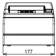
natural_image
Technical line drawing of a mechanical device with dimension标注 (no text or symbols)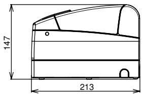
| No. microinterruttore | Regolazione | 0 (OFF) | 1 (ON) |
| Memory SW1-1 | Power ON Info | Valid | Not send |
| SW1-2 | Buffer Size | 4k bytes | 45 bytes |
| SW1-3 | Busy Condition | Full/Err | Full |
| SW1-4 | Receive Error | Print "?" | No Print |
| SW1-5 | CR mode | Ignored | LF |
| SW1-6 | Reserved | Fixed | - |
| SW1-7 | DSR Signal | Invalid | Valid |
| SW1-8 | Init Signal | Invalid | Valid |
| Memory SW2-1 | Reserved | - | Fixed |
| SW2-2 | Auto Cutter | Invalid | Valid |
| SW2-3 | Spool Print | Invalid | Valid |
| SW2-4 | Full Col Print | LineFeed | WaitData |
| SW2-5 | Resume aft PE | Next | Top |
| SW2-6 | Reserved | Fixed | - |
| SW2-7 | Reserved | Fixed | - |
| SW2-8 | PNE Sensor | Valid | Invalid |
| Memory SW3-1 | Resum Ctr Err | Valid | Invalid |
| SW3-2 | Reserved | Fixed | - |
| SW3-3 | Parallel 31 Pin | Valid | Invalid |
| SW3-4 | Reserved | Fixed | - |
| SW3-5 | Reserved | Fixed | - |
| SW3-6 | Reserved | Fixed | - |
| SW3-7 | CBM1000 Mode | Invalid | Valid |
| SW3-8 | Resum Open Err | Close | Command |
| Memory SW4-1 *M | P. Length Set | Auto Measure | Command |
| SW4-2 *M | Power on TOF | Invalid | Valid |
| SW4-3 | Feed&Cut at TOF | Invalid | Valid |
| SW4-4 *L | Paper Select *1 | Thermal Roll | BM.P / Lbl.P *4 |
| SW4-5 *L | Position detect *2 | Black Mark | Label |
| SW4-4 *M | Paper Select *1 | Thermal Roll | BM.P |
| SW4-5 *M | Position detect *2 | Black Mark | - |
| SW4-6 | Reserved | Fixed | - |
| SW4-7 | Reserved | Fixed | - |
| SW4-8 *3 | Prtial Only | Invalid | Valid |
| No. microinterruttore | Regolazione | 0 (OFF) | 1 (ON) |
| Memory SW5-1 | Buzzer | Valid | Invalid |
| SW5-2 | Line Pitch | 360 | 406 |
| SW5-3 | USB Mode | Virtual COM | Printer Class |
| SW5-4 | Reserved | Fixed | - |
| SW5-5 | Reserved | nvalid | - |
| SW5-6 | Reserved | Fixed | - |
| SW5-7 | Reserved | Fixed | - |
| SW5-8 | Reserved | Fixed | - |
| No. microinterruttore | Regolazione | Regolazione implicita | Valori di regolazione |
| Memory SW7-1 | Baud Rate | 9600 bps | 1200 bps, 2400 bps, 4800 bps, 9600 bps, 19200 bps, 38400 bps, 57600 bps, 115200 bps |
| SW7-2 | Data Length | 8Bits | 7Bits, 8Bits |
| SW7-3 | Stop Bit | 1Bit | 1Bit, 2Bits |
| SW7-4 | Parity | NONE | NONE, EVEN, ODD |
| SW7-5 | Flow Control | DTR/DSR | DTR/DSR, XON/XOFF |
| SW7-6 | DMA Control | Valid | Valid, Invalid |
| SW7-7 | VCom Protocol | PC Setting | PC Setting, DTR/DSR, XON/XOFF |
| Memory SW8-1 | Print Width | 832dots | 832dots(69 col.), 720dots(60col.), 660dots(55col), 576dots(48col.), 512dots(42col) |
| SW8-2 | Paper Type | 1 Color Normal | 1 Color Normal, 2 Color Normal |
| Memory SW9-1 | Code Page | PC437 | PC437/Katakana/PC850,858/PC860/PC863/PC865/PC852/PC866/PC857/WPC1252/PC864/Thai Code 18 |
| Memory SW9-2 | Int'Char Set | USA | USA, France, Germany, England, Denmark, Sweden, Italy, Spain, Japan, Norway, Denmark 2, Spain 2, Latin America, Korea Croatia, China |
| Memory SW9-3* | Kanji | OFF | ON, OFF |
| SW9-4* | JIS/Shift JIS | JIS | JIS, Shift JIS |
| Memory SW10-1 | Print Density | 100% | 70%, 75%, 80%, 85%, 90%, 95%, 100%, 105%, 110%, 115%, 120%, 125%, 130%, 135%, 140% |
| SW10-2 | Print Speed | Level 9 | Level 1, Level 2, Level 3, Level 4, Level 5, Level 6, Level 7, Level 8, Level 9 |
| SW10-3 | ACK Timing | Before Busy | Before Busy, Same Period, After Busy |
| SW10-4 | NV User | 192K bytes | 1K bytes, 64K bytes, 128K bytes, 192K bytes |
| SW10-5 | NV Graphic | 384K bytes | 0 byte, 64K bytes, 128K bytes, 192K bytes, 256K bytes, 320K bytes, 384K bytes |
Power ON notify setting (Valid)
Stato OFF: DEL ERRORE OFF
Stato ON: DEL ERRORE ON
CITIZEN is a registered trade mark of Citizen Holdings Co., Japan
Company names and product names in this manual are trademarks or registered trademarks of relevant companies.
Copyright© 2008 by CITIZEN SYSTEMS JAPAN CO., LTD.
NORMAS DE SEGURIDAD ... QUE DEBEN SER SEGUIDAS ESTRICTAMENTE

PRECAUCION
[Solamente CT-S4000L, CT-S4000DCL, CT-S4000M, CT-S4000DCM]
natural_image
Line drawing of a portable electronic device with ports and buttons (no text or symbols)CT-S4000
natural_image
Simple line drawing of a closed book or notebook (no text or symbols visible)natural_image
Technical illustration of a connector with a screwdriver inserted, showing internal components (no text or symbols)Interfaz Serie

natural_image
Diagram of a mechanical component with arrows indicating assembly or connection (no text or symbols)Interfaz Paralelo
natural_image
Illustration of an Ethernet cable with a connector and wall-mounted socket (no text or symbols)Interfaz USB

¡PRECAUCION!
natural_image
Line drawing of a mechanical device with a base and top plate (no text or symbols)natural_image
Line drawing of a mechanical device with rollers and clamps (no text or symbols)
Ver 5.3 Ajuste Manual de los "Memory Switches"

¡PRECAUCION!
natural_image
Line drawing of a room interior with furniture layout (no text or symbols)
natural_image
Technical line drawing of a rectangular electronic device with a 177-unit base and top panel (no text or symbols)
| No. de Conmutador | Ajuste | 0 (OFF) | 1 (ON) |
| Memory SW1-1 | Power ON Info | Valid | Not send |
| SW1-2 | Buffer Size | 4k bytes | 45 bytes |
| SW1-3 | Busy Condition | Full/Err | Full |
| SW1-4 | Receive Error | Print "?" | No Print |
| SW1-5 | CR mode | Ignored | LF |
| SW1-6 | Reserved | Fixed | - |
| SW1-7 | DSR Signal | Invalid | Valid |
| SW1-8 | Init Signal | Invalid | Valid |
| Memory SW2-1 | Reserved | - | Fixed |
| SW2-2 | Auto Cutter | Invalid | Valid |
| SW2-3 | Spool Print | Invalid | Valid |
| SW2-4 | Full Col Print | LineFeed | WaitData |
| SW2-5 | Resume aft PE | Next | Top |
| SW2-6 | Reserved | Fixed | - |
| SW2-7 | Reserved | Fixed | - |
| SW2-8 | PNE Sensor | Valid | Invalid |
| Memory SW3-1 | Resum Ctr Err | Valid | Invalid |
| SW3-2 | Reserved | Fixed | - |
| SW3-3 | Parallel 31 Pin | Valid | Invalid |
| SW3-4 | Reserved | Fixed | - |
| SW3-5 | Reserved | Fixed | - |
| SW3-6 | Reserved | Fixed | - |
| SW3-7 | CBM1000 Mode | Invalid | Valid |
| SW3-8 | Resum Open Err | Close | Command |
| Memory SW4-1 *M | P. Length Set | Auto Measure | Command |
| SW4-2 *M | Power on TOF | Invalid | Valid |
| SW4-3 | Feed&Cut at TOF | Invalid | Valid |
| SW4-4 *L | Paper Select *1 | Thermal Roll | BM.P / Lbl.P *4 |
| SW4-5 *L | Position detect *2 | Black Mark | Label |
| SW4-4 *M | Paper Select *1 | Thermal Roll | BM.P |
| SW4-5 *M | Position detect *2 | Black Mark | - |
| SW4-6 | Reserved | Fixed | - |
| SW4-7 | Reserved | Fixed | - |
| SW4-8 *3 | Prtial Only | Invalid | Valid |
| No. de Conmutador | Ajuste | 0 (OFF) | 1 (ON) |
| Memory SW5-1 | Buzzer | Valid | Invalid |
| SW5-2 | Line Pitch | 360 | 406 |
| SW5-3 | USB Mode | Virtual COM | Printer Class |
| SW5-4 | Reserved | Fixed | - |
| SW5-5 | Reserved | nvalid | - |
| SW5-6 | Reserved | Fixed | - |
| SW5-7 | Reserved | Fixed | - |
| SW5-8 | Reserved | Fixed | - |
| No. de Conmutador | Ajuste | Por omisión | Valores de Ajuste |
| Memory SW7-1 | Baud Rate | 9600 bps | 1200 bps, 2400 bps, 4800 bps, 9600 bps, 19200 bps, 38400 bps, 57600 bps, 115200 bps |
| SW7-2 | Data Length | 8Bits | 7Bits, 8Bits |
| SW7-3 | Stop Bit | 1Bit | 1Bit, 2Bits |
| SW7-4 | Parity | NONE | NONE, EVEN, ODD |
| SW7-5 | Flow Control | DTR/DSR | DTR/DSR, XON/XOFF |
| SW7-6 | DMA Control | Valid | Valid, Invalid |
| SW7-7 | VCom Protocol | PC Setting | PC Setting, DTR/DSR, XON/XOFF |
| Memory SW8-1 | Print Width | 832dots | 832dots(69 col.), 720dots(60col.), 660dots(55col), 576dots(48col.), 512dots(42col) |
| SW8-2 | Paper Type | 1 Color Normal | 1 Color Normal, 2 Color Normal |
| Memory SW9-1 | Code Page | PC437 | PC437/Katakana/PC850,858/PC860/PC863/PC865/PC852/PC866/PC857/WPC1252/PC864/Thai Code 18 |
| Memory SW9-2 | Int'Char Set | USA | USA, France, Germany, England, Denmark, Sweden, Italy, Spain, Japan, Norway, Denmark 2, Spain 2, Latin America, Korea Croatia, China |
| Memory SW9-3* | Kanji | OFF | ON, OFF |
| SW9-4* | JIS/Shift JIS | JIS | JIS, Shift JIS |
| Memory SW10-1 | Print Density | 100% | 70%, 75%, 80%, 85%, 90%, 95%, 100%, 105%, 110%, 115%, 120%, 125%, 130%, 135%, 140% |
| SW10-2 | Print Speed | Level 9 | Level 1, Level 2, Level 3, Level 4, Level 5, Level 6, Level 7, Level 8, Level 9 |
| SW10-3 | ACK Timing | Before Busy | Before Busy, Same Period, After Busy |
| SW10-4 | NV User | 192K bytes | 1K bytes, 64K bytes, 128K bytes, 192K bytes |
| SW10-5 | NV Graphic | 384K bytes | 0 byte, 64K bytes, 128K bytes, 192K bytes, 256K bytes, 320K bytes, 384K bytes |
Power ON notify setting (Valid)
Estado OFF:
If you want to dispose this product, do not mix with general household waste. There is a separate collection systems for used electronics products in accordance with legislation under the WEEE Directive (Directive 2002/96/EC) and is effective only within European Union.
Ge
natural_image
Symbol of a trash bin crossed out by two diagonal lines, representing no waste or discharge (no text or numbers present)
- LINE THERMAL PRINTER
- MODEL CT-S4000/CT-S4000DC
- CT-S4000L/CT-S4000DCL
- CT-S4000M/CT-S4000DCM
- User's Manual
- Mode d'emploi
- Benutzerhandbuch
- Manuale dell'utente
- Manual de Usuario
- Declaration of Conformity
- Sicherheitshinweis
- THE TABLE OF CONTENTS
- SAFETY PRECAUTIONS ... WHICH SHOULD BE STRICTLY OBSERVED
- WARNING
- CAUTION
- DAILY MAINTENANCE
- GENERAL OUTLINE
- Features
- Unpacking
- Model Classification
- Printer Appearance
- Operation Panel
- Rear Connectors
- Printer Cover Inside
- Connecting the AC Power Cord
- CAUTION!
- Connecting Interface Cables
- Connecting the Cash Drawer
- Connector Pin Configuration
- Electrical characteristics
- DRSW signal
- Drive Circuit (printer side)
- Installing the Printer
- Partition for Paper Roll
- Setting DIP Switch
- Adjusting the Paper Near-end Sensor
- Setting/Replacing the paper roll
- Removing Jammed Paper
- Periodic cleaning
- Self-printing
- Hexadecimal Dump Printing
- Error Indication
- ● Paper end
- ● Printer cover open
- ● Cutter lock
- ● Thermal head overheat
- ● Paper jam error
- ● Power switch operation error
- ● Black Mark detection error (in Black Mark mode)
- ● Waiting for paper (label) cutting
- ● Paper (label) detection error
- When the Paper Cover Cannot Be Opened
- External Views and Dimensions
- Printing Paper
- Manual Setting of Memory Switch
- Manual Setting of Memory Switch (Memory SW)
- Selecting Paper Type \*L, \*M
- Enter Selecting Paper Type mode.
- Select Paper Type.
- Save the selected Paper Type to the Printer.
- Adjusting Paper Sensor *L , *M
- Enter Adjusting Paper Sensor mode.
- Set Paper to be adjusted to the Printer.
- Adjust Paper Sensor.
- Perform Paper Measuring operation
- Full cutting label paper * L
- FRANÇAIS
- PRÉCAUTIONS GÉNÉRALES
- PRÉCAUTIONS DE SÉCURITÉ ... QUI DEVRAIENT ÊTRE OBSERVÉES RIGOUREUSEMENT
- ATTENTION
- ATTENTION!
- VORSICHT
- VORSICHT!
- Druckpapier
- PRECAUZIONI DI SICUREZZA ... DA OSSERVARE RIGOROSAMENTE
- ATTENZIONE
- ATTENZIONE!
- NORMAS DE SEGURIDAD ... QUE DEBEN SER SEGUIDAS ESTRICTAMENTE
- PRECAUCION
- ¡PRECAUCION!
- Ge
Brand : CITIZEN
Model : CT-S4000L
Category : Thermal printer