
NBG410W3G - Wireless Router ZYXEL - Free user manual and instructions
Find the device manual for free NBG410W3G ZYXEL in PDF.
| Product Type | Wireless Router |
| Brand | ZYXEL |
| Model | NBG410W3G |
| Dimensions (L x W x H) | Approximately 170 x 120 x 35 mm |
| Weight | Approximately 250 g |
| Power Supply | 12 V DC, 1 A power adapter |
| Power Consumption | Less than 12 W |
| Wi-Fi Standard | 802.11 b/g (2.4 GHz) |
| Maximum Wireless Speed | Up to 54 Mbps |
| Ports | 1 WAN port (RJ45) + 4 LAN ports (RJ45) 10/100 Mbps |
| Main Features | Router, Wi-Fi access point, firewall, 3G/4G support via USB |
| Wireless Security | WEP, WPA, WPA2, MAC filtering |
| Reset Button | Yes, on the back of the device |
| Antenna | 2 removable external antennas |
| Operating Temperature | 0 to 40 °C |
| Operating Humidity | 10 to 90% non-condensing |
| Certifications | CE, FCC, IC |
| Package Contents | Router, power adapter, Ethernet cable, quick installation guide |
| Care and Cleaning | Use a dry, soft cloth. Do not use abrasive products. |
| Spare Parts and Repairability | Spare parts are not directly available. Contact ZYXEL customer service. |
| Warranty | 2 years (depending on country) |
Frequently Asked Questions - NBG410W3G ZYXEL
User questions about NBG410W3G ZYXEL
0 question about this device. Answer the ones you know or ask your own.
Ask a new question about this device
Download the instructions for your Wireless Router in PDF format for free! Find your manual NBG410W3G - ZYXEL and take your electronic device back in hand. On this page are published all the documents necessary for the use of your device. NBG410W3G by ZYXEL.
USER MANUAL NBG410W3G ZYXEL
About This User's Guide
Intended Audience
This manual is intended for people who want to configure the ZyXEL Device using the web configurator. You should have at least a basic knowledge of TCP/IP networking concepts and topology.
Related Documentation
- Quick Start Guide
The Quick Start Guide is designed to help you get up and running right away. It contains information on setting up your network and configuring for Internet access.
Web Configurator Online Help
Embedded web help for descriptions of individual screens and supplementary information.
- Supporting Disk
Refer to the included CD for support documents.
ZyXEL Web Site
Please refer to www.zyxel.com for additional support documentation and product certifications.
User Guide Feedback
Help us help you. Send all User Guide-related comments, questions or suggestions for improvement to the following address, or use e-mail instead. Thank you!
The Technical Writing Team,
ZyXEL Communications Corp.,
6 Innovation Road II,
Science-Based Industrial Park,
Hsinchu, 300, Taiwan.
E-mail: techwriters@zyxel.com.tw
Document Conventions
Warnings and Notes
These are how warnings and notes are shown in this User's Guide.

Warnings tell you about things that could harm you or your device.

Notes tell you other important information (for example, other things you may need to configure or helpful tips) or recommendations.
Syntax Conventions
- The NBG410W3G and NBG412W3G may be referred to as the "ZyXEL Device", the "device", the "system", or the "NBG410W3G Series" in this User's Guide.
- Product labels, screen names, field labels and field choices are all in bold font.
- A key stroke is denoted by square brackets and uppercase text, for example, [ENTER] means the "enter" or "return" key on your keyboard.
- “Enter” means for you to type one or more characters and then press the [ENTER] key. "Select" or "choose" means for you to use one of the predefined choices.
- A right angle bracket (>) within a screen name denotes a mouse click. For example, Maintenance > Log > Log Setting means you first click Maintenance in the navigation panel, then the Log sub menu and finally the Log Setting tab to get to that screen.
- Units of measurement may denote the "metric" value or the "scientific" value. For example, "k" for kilo may denote "1000" or "1024", "M" for mega may denote "1000000" or "1048576" and so on.
- "e.g.," is a shorthand for "for instance", and "i.e.," means "that is" or "in other words".
Icons Used in Figures
Figures in this User's Guide may use the following generic icons. The ZyXEL Device icon is not an exact representation of your device.
| ZyXEL Device | Computer | Notebook computer |
| Server | DSLAM | Firewall |
| Telephone | Switch | Router |
SafetyWarnings

For your safety, be sure to read and follow all warning notices and instructions.
- Do NOT use this product near water, for example, in a wet basement or near a swimming pool.
- Do NOT expose your device to dampness, dust or corrosive liquids.
- Do NOT store things on the device.
- Do NOT install, use, or service this device during a thunderstorm. There is a remote risk of electric shock from lightning.
- Connect ONLY suitable accessories to the device.
- Do NOT open the device or unit. Opening or removing covers can expose you to dangerous high voltage points or other risks. ONLY qualified service personnel should service or disassemble this device. Please contact your vendor for further information.
- Make sure to connect the cables to the correct ports.
- Place connecting cables carefully so that no one will step on them or stumble over them.
- Always disconnect all cables from this device before servicing or disassembling.
- Use ONLY an appropriate power adaptor or cord for your device.
- Connect the power adaptor or cord to the right supply voltage (for example, 110V AC in North America or 230V AC in Europe).
- Do NOT remove the plug and connect it to a power outlet by itself; always attach the plug to the power adaptor first before connecting it to a power outlet.
- Do NOT allow anything to rest on the power adaptor or cord and do NOT place the product where anyone can walk on the power adaptor or cord.
- Do NOT use the device if the power adaptor or cord is damaged as it might cause electrocution.
- If the power adaptor or cord is damaged, remove it from the power outlet.
- Do NOT attempt to repair the power adaptor or cord. Contact your local vendor to order a new one.
- Do not use the device outside, and make sure all the connections are indoors. There is a remote risk of electric shock from lightning.
- Do NOT obstruct the device ventilation slots, as insufficient airflow may harm your device.
- Antenna Warning! This device meets ETSI and FCC certification requirements when using the included antenna(s). Only use the included antenna(s).
- If you wall mount your device, make sure that no electrical lines, gas or water pipes will be damaged.
This product is recyclable. Dispose of it properly.

Contents Overview
Introduction 33
Getting to Know Your ZyXEL Device 35
Introducing the Web Configurator 43
Wizard Setup 59
Tutorials 65
Network 99
LAN Screens 101
WAN Screens 111
DMZ Screens 135
Wireless 145
Wi-Fi 147
Security 165
Firewall 167
Authentication Server 191
Certificates 195
Advanced 223
Network Address Translation (NAT) 225
Static Route 243
DNS 247
Remote Management 259
UPnP 281
Custom Application 291
ALG Screen 293
Logs and Maintenance 299
Logs Screens 301
Maintenance 325
Troubleshooting and Specifications 337
Troubleshooting 339
Product Specifications 345
Appendices and Index 351
Table of Contents
About This User's Guide 3
Document Conventions 4
SafetyWarnings 6
Contents Overview 9
Table of Contents 11
List of Figures 21
List of Tables 29
Part I: Introduction 33
Chapter 1 Getting to Know Your ZyXEL Device 35
1.1 Overview 35
1.2 Applications for the ZyXEL Device 35
1.2.1 3G WAN Application 35
1.2.2 Secure Broadband Internet Access via Cable or DSL Modem 36
1.3 Ways to Manage the ZyXEL Device 36
1.4 Configuring Your ZyXEL Device's Security Features 37
1.4.1 Control Access to Your Device 37
1.4.2 Wireless Security 37
1.4.3 Firewall 37
1.4.4 NAT 38
1.4.5 UPnP 38
1.5 Maintaining Your ZyXEL Device 38
1.5.1 Front Panel Lights 39
Chapter 2 Introducing the Web Configurator 43
2.1 Web Configurator Overview 43
2.2 Accessing the ZyXEL Device Web Configurator 43
2.3 Resetting the ZyXEL Device 45
2.3.1 Procedure To Use The Reset Button 45
2.3.2 Uploading a Configuration File Via Console Port 45
2.4 Navigating the ZyXEL Device Web Configurator 46
2.4.1 Title Bar 46
2.4.2 Main Window 47
2.4.3 HOME Screen 47
2.4.4 Navigation Panel 52
2.4.5 Port Statistics 54
2.4.6 Show Statistics: Line Chart 55
2.4.7 DHCP Table Screen 56
Chapter 3
Wizard Setup 59
3.1 Wizard Setup Overview 59
3.2 Internet Access 59
3.2.1 ISP Parameters 59
3.2.2 Internet Access Wizard Setup Complete 64
Chapter 4
Tutorials 65
4.1 DMZ Overview 65
4.2 DMZ Setup Example 66
4.2.1 Basic Setup 66
4.2.2 Advanced Setup 68
4.3 Firewall Rule Setup 69
4.4 Setting Up a VoIP Phone with H.323 72
4.5 Using NAT with Multiple Public IP Addresses 77
4.5.1 Example Parameters and Scenario 77
4.5.2 Configuring the WAN Connection with a Static IP Address 78
4.5.3 Public IP Address Mapping 82
4.5.4 Forwarding Traffic from the WAN to a Local Computer 87
4.5.5 Allow WAN-to-LAN Traffic through the Firewall 89
4.5.6 Testing the Connections 96
4.6 Using NAT with Multiple Game Players 96
Part II: Network 99
Chapter 5
LAN Screens 101
5.1 LAN, WAN and the ZyXEL Device 101
5.2 IP Address and Subnet Mask 101
5.2.1 Private IP Addresses 102
5.3 DHCP 102
5.3.1 IP Pool Setup 103
5.4 RIP Setup 103
5.5 Multicast 103
5.6 WINS 104
5.7 LAN 104
5.8 LAN Static DHCP 106
5.9 LAN IP Alias 107
5.10 LAN Port Roles 109
Chapter 6
WAN Screens 111
6.1 WAN Overview 111
6.2 Multiple WAN 111
6.3 TCP/IP Priority (Metric) 112
6.4 WAN General 112
6.5 WAN IP Address Assignment 115
6.6 DNS Server Address Assignment 116
6.7 WAN MAC Address 116
6.8 WAN 1 117
6.8.1 WAN Ethernet Encapsulation 117
6.8.2 PPPoE Encapsulation 120
6.8.3 PPTP Encapsulation 123
6.9 3G (WAN 2) 126
6.10 Traffic Redirect 133
6.11 Configuring Traffic Redirect 134
Chapter 7
DMZ Screens 135
7.1 DMZ 135
7.2 Configuring DMZ 135
7.3 DMZ Static DHCP 138
7.4 DMZ IP Alias 139
7.5 DMZ Public IP Address Example 141
7.6 DMZ Private and Public IP Address Example 141
7.7 DMZ Port Roles 142
Part III: Wireless 145
Chapter 8
Wi-Fi 147
8.1 Wi-Fi Introduction 147
8.2 Wireless Security Overview 148
8.2.1 SSID 148
8.2.2 MAC Address Filter 148
8.2.3 User Authentication 149
8.2.4 Encryption 149
8.2.5 Additional Installation Requirements for Using 802.1x 151
8.3 Wireless Card 151
8.3.1 SSID Profile 153
8.4 Configuring Wireless Security 154
8.4.1 No Security 156
8.4.2 Static WEP 156
8.4.3 IEEE 802.1x Only 157
8.4.4 IEEE 802.1x + Static WEP 158
8.4.5 WPA, WPA2, WPA2-MIX 160
8.4.6 WPA-PSK, WPA2-PSK, WPA2-PSK-MIX 161
8.5 MAC Filter 162
Part IV: Security 165
Chapter 9
Firewall 167
9.1 Firewall Overview 167
9.2 Packet Direction Matrix 168
9.3 Packet Direction Examples 169
9.4 Security Considerations 170
9.5 Firewall Rules Example 171
9.6 Asymmetrical Routes 173
9.6.1 Asymmetrical Routes and IP Alias 173
9.7 Firewall Default Rule 173
9.8 Firewall Rule Summary 175
9.8.1 Firewall Edit Rule 177
9.9 Anti-Probing 180
9.10 Firewall Thresholds 181
9.10.1 Threshold Values 182
9.11 Threshold Screen 182
9.12 Service 184
9.12.1 Firewall Edit Custom Service 185
9.13 My Service Firewall Rule Example 186
Chapter 10
Authentication Server 191
10.1 Authentication Server Overview 191
10.2 Local User Database 191
10.3 RADIUS 193
Chapter 11
Certificates 195
11.1 Certificates Overview 195
11.1.1 Advantages of Certificates 196
11.2 Self-signed Certificates 196
11.3 Verifying a Certificate 196
11.3.1 Checking the Fingerprint of a Certificate on Your Computer 196
11.4 Configuration Summary 197
11.5 My Certificates 198
11.6 My Certificate Details 200
11.7 My Certificate Export 202
11.7.1 Certificate File Export Formats 202
11.8 My Certificate Import 203
11.8.1 Certificate File Formats 203
11.9 My Certificate Create 205
11.10 Trusted CAs 209
11.11 Trusted CA Details 211
11.12 Trusted CA Import 214
11.13 Trusted Remote Hosts 215
11.14 Trusted Remote Hosts Import 217
11.15 Trusted Remote Host Certificate Details 218
11.16 Directory Servers 220
11.17 Directory Server Add or Edit 221
Part V: Advanced 223
Chapter 12
Network Address Translation (NAT) 225
12.1 NAT Overview 225
12.1.1 NAT Definitions 225
12.1.2 What NAT Does 226
12.1.3 How NAT Works 226
12.1.4 NAT Application 227
12.1.5 Port Restricted Cone NAT 228
12.1.6 NAT Mapping Types 229
12.2 Using NAT 230
12.2.1 SUA (Single User Account) Versus NAT 230
12.3 NAT Overview Screen 230
12.4 NAT Address Mapping 232
12.4.1 What NAT Does 232
12.4.2 NAT Address Mapping Edit 234
12.5 Port Forwarding 235
12.5.1 Default Server IP Address 235
12.5.2 Port Forwarding: Services and Port Numbers 236
12.5.3 Configuring Servers Behind Port Forwarding (Example) 236
12.5.4 NAT and Multiple WAN 237
12.5.5 Port Translation 237
12.6 Port Forwarding Screen 238
12.7 Port Triggering 240
Chapter 13
Static Route 243
13.1 IP Static Route 243
13.2 IP Static Route 244
13.2.1 IP Static Route Edit 245
Chapter 14
DNS 247
14.1 DNS Overview 247
14.2 DNS Server Address Assignment 247
14.3 DNS Servers 247
14.4 Address Record 248
14.4.1 DNS Wildcard 248
14.5 Name Server Record 248
14.5.1 Private DNS Server 248
14.6 System Screen 248
14.6.1 Adding an Address Record 250
14.6.2 Inserting a Name Server Record 251
14.7 DNS Cache 252
14.8 Configure DNS Cache 252
14.9 Configuring DNS DHCP 254
14.10 Dynamic DNS 255
14.10.1 DYNDNS Wildcard 255
14.10.2 High Availability 256
14.11 Configuring Dynamic DNS 256
Chapter 15
Remote Management 259
15.1 Remote Management Overview 259
15.1.1 Remote Management Limitations 260
15.1.2 System Timeout 260
15.2 WWW (HTTP and HTTPS) 260
15.3 WWW 261
15.4 HTTPS Example 263
15.4.1 Internet Explorer Warning Messages 263
15.4.2 Netscape Navigator Warning Messages 263
15.4.3 Avoiding the Browser Warning Messages 264
15.4.4 Login Screen 265
15.5 SSH 267
15.6 How SSH Works 267
15.7 SSH Implementation on the ZyXEL Device 268
15.7.1 Requirements for Using SSH 268
15.8 Configuring SSH 269
15.9 Secure Telnet Using SSH Examples 270
15.9.1 Example 1: Microsoft Windows 270
15.9.2 Example 2: Linux 270
15.10 Secure FTP Using SSH Example 271
15.11 Telnet 272
15.12 Configuring TELNET 272
15.13 FTP 273
15.14 SNMP 274
15.14.1 Supported MIBs 275
15.14.2 SNMP Traps 276
15.14.3 REMOTE MANAGEMENT: SNMP 276
15.15 DNS 277
15.16 Introducing Vantage CNM 278
15.17 Configuring CNM 278
15.17.1 Additional Configuration for Vantage CNM 280
Chapter 16
UPnP 281
16.1 Universal Plug and Play Overview 281
16.1.1 How Do I Know If I'm Using UPnP? 281
16.1.2 NAT Traversal 281
16.1.3 Cautions with UPnP 281
16.1.4 UPnP and ZyXEL 282
16.2 Configuring UPnP 282
16.3 Displaying UPnP Port Mapping 283
16.4 Installing UPnP in Windows Example 284
16.4.1 Installing UPnP in Windows Me 285
16.4.2 Installing UPnP in Windows XP 286
16.5 Using UPnP in Windows XP Example 286
16.5.1 Auto-discover Your UPnP-enabled Network Device 287
16.5.2 Web Configurator Easy Access 288
Chapter 17
Custom Application 291
17.1 Custom Application 291
17.2 Custom Application Configuration 291
Chapter 18
ALG Screen 293
18.1 ALG Introduction 293
18.1.1 ALG and NAT 293
18.1.2 ALG and the Firewall 293
18.1.3 ALG and Multiple WAN 294
18.2 FTP 294
18.3 H.323 294
18.4 RTP 294
18.4.1 H.323 ALG Details 294
18.5 SIP 295
18.5.1 STUN 295
18.5.2 SIP ALG Details 296
18.5.3 SIP Signaling Session Timeout 296
18.5.4 SIP Audio Session Timeout 296
18.6 ALG Screen 296
Part VI: Logs and Maintenance 299
Chapter 19
Logs Screens 301
19.1 Configuring View Log 301
19.2 Log Description Example 302
19.2.1 About the Certificate Not Trusted Log 303
19.3 Configuring Log Settings 304
19.4 Configuring Reports 307
19.4.1 Viewing Web Site Hits 309
19.4.2 Viewing Host IP Address 309
19.4.3 Viewing Protocol/Port 310
19.4.4 System Reports Specifications 312
19.5 Log Descriptions 312
19.6 Syslog Logs 323
Chapter 20
Maintenance 325
20.1 Maintenance Overview 325
20.2 General Setup and System Name 325
20.2.1 General Setup 325
20.3 Configuring Password 326
20.4 Time and Date 327
20.5 Pre-defined NTP Time Server Pools 330
20.5.1 Resetting the Time 330
20.5.2 Time Server Synchronization 330
20.6 F/W Upload Screen 331
20.7 Backup and Restore 333
20.7.1 Backup Configuration 334
20.7.2Restore Configuration 334
20.7.3 Back to Factory Defaults 335
20.8 Restart Screen 336
Part VII: Troubleshooting and Specifications 337
Chapter 21
Troubleshooting 339
21.1 Power, Hardware Connections, and LEDs 339
21.2 ZyXEL Device Access and Login 340
21.3 Internet Access 342
21.4 3G Connection 343
Chapter 22
Product Specifications 345
22.1 General ZyXEL Device Specifications 345
22.2 Wall-mounting Instructions 347
22.3 Power Adaptor Specifications 349
Part VIII: Appendices and Index 351
Appendix A Pop-up Windows, JavaScripts and Java Permissions 353
Appendix B Setting up Your Computer's IP Address 361
Appendix C IP Addresses and Subnetting 377
Appendix D Common Services 385
Appendix E Wireless LANs 389
Appendix F Importing Certificates 403
Appendix G Legal Information 415
Appendix H Customer Support 419
Index 425
List of Figures
Figure 1 3G WAN Application 36
Figure 2 Secure Internet Access via Cable or DSL Modem 36
Figure 3 Front Panel 39
Figure 4 Login Screen 44
Figure 5 Change Password Screen 44
Figure 6 Replace Certificate Screen 44
Figure 7 Example Xmodem Upload 46
Figure 8 HOME Screen 46
Figure 9 Web Configurator HOME Screen 47
Figure 10 HOME > Show Statistics 55
Figure 11 HOME > Show Statistics > Line Chart 56
Figure 12 HOME > DHCP Table 57
Figure 13 Wizard Setup Welcome 59
Figure 14 ISP Parameters: Ethernet Encapsulation 60
Figure 15 ISP Parameters: PPPoE Encapsulation 61
Figure 16 ISP Parameters: PPTP Encapsulation 63
Figure 17 Internet Access Setup Complete 64
Figure 18 DMZ Overview 65
Figure 19 DMZ Tutorial: DMZ Setup 66
Figure 20 DMZ Tutorial: NETWORK > DMZ > Static DHCP 67
Figure 21 DMZ Tutorial: NETWORK > DMZ
Figure 22 DMZ Tutorial: ADVANCED > NAT Overview 68
Figure 23 DMZ Tutorial: ADVANCED > ALG 68
Figure 24 DMZ Tutorial: ADVANCED > NAT > Port Forwarding 69
Figure 25 DMZ Tutorial: SECURITY > Firewall > Rule Summary 70
Figure 26 DMZ Tutorial: NETWORK > Firewall > Rule Summary: Firewall - Edit 71
Figure 27 DMZ Tutorial: SECURITY > Firewall > Rule Summary Example 72
Figure 28 Tutorial: H.323 Phone Setup 72
Figure 29 H.323 Tutorial: NETWORK > LAN > Static DHCP 73
Figure 30 H.323 Tutorial: ADVANCED > ALG 73
Figure 31 H.323 Tutorial: ADVANCED > NAT > Port Forwarding 74
Figure 32 H.323 Tutorial: SECURITY > Firewall > Rule Summary 74
Figure 33 H.323 Tutorial: SECURITY > Firewall > Rule Summary 76
Figure 34 H.323 Tutorial: SECURITY > Firewall > Rule Summary 77
Figure 35 Tutorial Example: Using NAT with Static Public IP Addresses 78
Figure 36 Tutorial Example: WAN Connection with a Static Public IP Address 79
Figure 37 Tutorial Example: WAN 1 Screen 79
Figure 38 Tutorial Example: DNS > System 80
Figure 39 Tutorial Example: DNS > System Edit-1 80
Figure 40 Tutorial Example: DNS > System Edit-2
Figure 41 Tutorial Example: DNS > System: Done 81
Figure 42 Tutorial Example: Status 82
Figure 43 Tutorial Example: Mapping Multiple Public IP Addresses to Inside Servers 83
Figure 44 Tutorial Example: NAT > NAT Overview 84
Figure 45 Tutorial Example: NAT > Address Mapping 85
Figure 46 Tutorial Example: NAT Address Mapping Edit: One-to-One (1) 85
Figure 47 Tutorial Example: NAT Address Mapping Edit: One-to-One (2) 86
Figure 48 Tutorial Example: NAT Address Mapping Edit: Many-to-One 86
Figure 49 Tutorial Example: NAT Address Mapping Done 87
Figure 50 Tutorial Example: Forwarding Incoming FTP Traffic to a Local Computer 88
Figure 51 Tutorial Example: NAT Address Mapping Edit: Server 88
Figure 52 Tutorial Example: NAT Port Forwarding 89
Figure 53 Tutorial Example: Forwarding Incoming FTP Traffic to a Local Computer 89
Figure 54 Tutorial Example: Firewall Default Rule 90
Figure 55 Tutorial Example: Firewall Rule: WAN1 to LAN 90
Figure 56 Tutorial Example: Firewall Rule: WAN to LAN Address Edit for Web Server 91
Figure 57 Tutorial Example: Firewall Rule: WAN to LAN Service Edit for Web Server 92
Figure 58 Tutorial Example: Firewall Rule: WAN to LAN Address Edit for Mail Server 93
Figure 59 Tutorial Example: Firewall Rule: WAN to LAN Service Edit for Mail Server 93
Figure 60 Tutorial Example: Firewall Rule: WAN to LAN Address Edit for FTP Server 94
Figure 61 Tutorial Example: Firewall Rule: WAN to LAN Service Edit for FTP Server 95
Figure 62 Tutorial Example: Firewall Rule Summary 95
Figure 63 Tutorial Example: NAT Address Mapping Done: Game Playing 97
Figure 64 LAN and WAN 101
Figure 65 NETWORK > LAN 104
Figure 66 NETWORK > LAN > Static DHCP 107
Figure 67 Physical Network & Partitioned Logical Networks 108
Figure 68 NETWORK > LAN > IP Alias 108
Figure 69 NETWORK > LAN > Port Roles 110
Figure 70 Port Roles Change Complete 110
Figure 71 NETWORK > WAN General 113
Figure 72 NETWORK > WAN > WAN 1 (Ethernet Encapsulation) 117
Figure 73 NETWORK > WAN > WAN 1 (PPPoE Encapsulation) 121
Figure 74 NETWORK > WAN > WAN 1 (PPTP Encapsulation) 124
Figure 75 NETWORK > WAN > 3G (WAN 2) 129
Figure 76 Traffic Redirect WAN Setup 133
Figure 77 Traffic Redirect LAN Setup 133
Figure 78 NETWORK > WAN > Traffic Redirect 134
Figure 79 NETWORK > DMZ 136
Figure 80 NETWORK > DMZ > Static DHCP 138
Figure 81 NETWORK > DMZ > IP Alias 140
Figure 82 DMZ Public Address Example 141
Figure 83 DMZ Private and Public Address Example 142
Figure 84 NETWORK > DMZ > Port Roles 143
Figure 85 Example of a Wireless Network 147
Figure 86 WIRELESS > Wi-Fi > Wireless Card 151
Figure 87 WIRELESS > Wi-Fi > Configuring SSID 154
Figure 88 WIRELESS > Wi-Fi > Security 155
Figure 89 WIRELESS > Wi-Fi > Security: None 156
Figure 90 WIRELESS > Wi-Fi > Security: WEP 157
Figure 91 WIRELESS > Wi-Fi > Security: 802.1x Only 158
Figure 92 WIRELESS > Wi-Fi > Security: 802.1x + Static WEP 159
Figure 93 WIRELESS > Wi-Fi > Security: WPA, WPA2 or WPA2-MIX 160
Figure 94 WIRELESS > Wi-Fi > Security: WPA(2)-PSK 161
Figure 95 WIRELESS > Wi-Fi > MAC Filter 163
Figure 96 Default Firewall Action 167
Figure 97 SECURITY > FIREWALL > Default Rule 168
Figure 98 Default Block Traffic From WAN1 to DMZ Example 169
Figure 99 Blocking All LAN to WAN IRC Traffic Example 171
Figure 100 Limited LAN to WAN IRC Traffic Example 172
Figure 101 Using IP Alias to Solve the Triangle Route Problem 173
Figure 102 SECURITY > FIREWALL > Default Rule 174
Figure 103 SECURITY > FIREWALL > Rule Summary 176
Figure 104 SECURITY > FIREWALL > Rule Summary > Edit 178
Figure 105 SECURITY > FIREWALL > Anti-Probing 180
Figure 106 Three-Way Handshake 181
Figure 107 SECURITY > FIREWALL > Threshold 182
Figure 108 SECURITY > FIREWALL > Service 184
Figure 109 Firewall Edit Custom Service 185
Figure 110 My Service Firewall Rule Example: Service 186
Figure 111 My Service Firewall Rule Example: Edit Custom Service 187
Figure 112 My Service Firewall Rule Example: Rule Summary 187
Figure 113 My Service Firewall Rule Example: Rule Edit: Source and Destination Addresses 188
Figure 114 My Service Firewall Rule Example: Edit Rule: Service Configuration 189
Figure 115 My Service Firewall Rule Example: Rule Summary: Completed 190
Figure 116 SECURITY > AUTHSERVER > Local User Database 192
Figure 117 SECURITY > AUTHSERVER > RADIUS 193
Figure 118 Certificates on Your Computer 196
Figure 119 Certificate Details 197
Figure 120 Certificate Configuration Overview 197
Figure 121 SECURITY > CERTIFICATES > My Certificates 198
Figure 122 SECURITY > CERTIFICATES > My Certificates > Details 200
Figure 123 SECURITY > CERTIFICATES > My Certificates > Export 202
Figure 124 SECURITY > CERTIFICATES > My Certificates > Import 204
Figure 125 SECURITY > CERTIFICATES > My Certificates > Import: PKCS#12 204
Figure 126 SECURITY > CERTIFICATES > My Certificates > Create (Basic) 205
Figure 127 SECURITY > CERTIFICATES > My Certificates > Create (Advanced) 206
Figure 128 SECURITY > CERTIFICATES > Trusted CAs 210
Figure 129 SECURITY > CERTIFICATES > Trusted CAs > Details 212
Figure 130 SECURITY > CERTIFICATES > Trusted CAs > Import 215
Figure 131 SECURITY > CERTIFICATES > Trusted Remote Hosts 216
Figure 132 SECURITY > CERTIFICATES > Trusted Remote Hosts > Import 217
Figure 133 SECURITY > CERTIFICATES > Trusted Remote Hosts > Details 218
Figure 134 SECURITY > CERTIFICATES > Directory Servers 220
Figure 135 SECURITY > CERTIFICATES > Directory Server > Add 221
Figure 136 How NAT Works 227
Figure 137 NAT Application With IP Alias 228
Figure 138 Port Restricted Cone NAT Example 229
Figure 139 ADVANCED > NAT > NAT Overview 231
Figure 140 ADVANCED > NAT > Address Mapping 233
Figure 141 ADVANCED > NAT > Address Mapping > Edit 234
Figure 142 Multiple Servers Behind NAT Example 237
Figure 143 Port Translation Example 238
Figure 144 ADVANCED > NAT > Port Forwarding 239
Figure 145 Trigger Port Forwarding Process: Example 240
Figure 146 ADVANCED > NAT > Port Triggering 241
Figure 147 Example of Static Routing Topology 243
Figure 148 ADVANCED >STATIC ROUTE > IP Static Route 244
Figure 149 ADVANCED > STATIC ROUTE > IP Static Route > Edit 245
Figure 150 ADVANCED > DNS > System DNS 249
Figure 151 ADVANCED > DNS > Add (Address Record) 250
Figure 152 ADVANCED > DNS > Insert (Name Server Record) 251
Figure 153 ADVANCED > DNS > Cache 253
Figure 154 ADVANCED > DNS > DHCP 254
Figure 155 ADVANCED > DNS > DDNS 256
Figure 156 Secure and Insecure Remote Management From the WAN 259
Figure 157 HTTPS Implementation 261
Figure 158 ADVANCED > REMOTE MGMT > WWW 262
Figure 159 Security Alert Dialog Box (Internet Explorer) 263
Figure 160 Security Certificate 1 (Netscape) 264
Figure 161 Security Certificate 2 (Netscape) 264
Figure 162 Example: Lock Denoting a Secure Connection 265
Figure 163 Replace Certificate 266
Figure 164 Device-specific Certificate 266
Figure 165 Common ZyXEL Device Certificate 267
Figure 166 SSH Communication Over the WAN Example 267
Figure 167 How SSH Works 268
Figure 168 ADVANCED > REMOTE MGMT > SSH 269
Figure 169 SSH Example 1: Store Host Key 270
Figure 170 SSH Example 2: Test 270
Figure 171 SSH Example 2: Log in 271
Figure 172 Secure FTP: Firmware Upload Example 272
Figure 173 ADVANCED > REMOTE MGMT > Telnet 272
Figure 174 ADVANCED > REMOTE MGMT > FTP 273
Figure 175 SNMP Management Model 275
Figure 176 ADVANCED > REMOTE MGMT > SNMP 276
Figure 177 ADVANCED > REMOTE MGMT > DNS 278
Figure 178 ADVANCED > REMOTE MGMT > CNM 279
Figure 179 ADVANCED > UPnP 282
Figure 180 ADVANCED > UPnP > Ports 283
Figure 181 ADVANCED > Custom APP 292
Figure 182 H.323 ALG Example 295
Figure 183 H.323 with Multiple WAN IP Addresses 295
Figure 184 SIP ALG Example 296
Figure 185 ADVANCED > ALG 297
Figure 186 LOGS > View Log 301
Figure 187 myZyXEL.com: Download Center 303
Figure 188 myZyXEL.com: Certificate Download 304
Figure 189 LOGS > Log Settings 305
Figure 190 LOGS > Reports 308
Figure 191 LOGS > Reports: Web Site Hits Example 309
Figure 192 LOGS > Reports: Host IP Address Example 310
Figure 193 LOGS > Reports: Protocol/Port Example 311
Figure 194 MAINTENANCE > General Setup 326
Figure 195 MAINTENANCE > Password 327
Figure 196 MAINTENANCE > Time and Date 328
Figure 197 Synchronization in Process 330
Figure 198 Synchronization is Successful 331
Figure 199 Synchronization Fail 331
Figure 200 MAINTENANCE > Firmware Upload 332
Figure 201 Firmware Upload In Process 332
Figure 202 Network Temporarily Disconnected 333
Figure 203 Firmware Upload Error 333
Figure 204 MAINTENANCE > Backup and Restore 334
Figure 205 Configuration Upload Successful 335
Figure 206 Network Temporarily Disconnected 335
Figure 207 Configuration Upload Error 335
Figure 208 Reset Warning Message 336
Figure 209 MAINTENANCE > Restart 336
Figure 210 Wall-mounting Example 348
Figure 211 Masonry Plug and M4 Tap Screw 348
Figure 212 Pop-up Blocker 353
Figure 213 Internet Options: Privacy 354
Figure 214 Internet Options: Privacy 355
Figure 215 Pop-up Blocker Settings 355
Figure 216 Internet Options: Security 356
Figure 217 Security Settings - Java Scripting 357
Figure 218 Security Settings - Java 357
Figure 219 Java (Sun) 358
Figure 220 Mozilla Firefox: Tools > Options 359
Figure 221 Mozilla Firefox Content Security 359
Figure 222 Windows 95/98/Me: Network: Configuration 362
Figure 223 Windows 95/98/Me: TCP/IP Properties: IP Address 363
Figure 224 Windows 95/98/Me: TCP/IP Properties: DNS Configuration 364
Figure 225 Windows XP: Start Menu 365
Figure 226 Windows XP: Control Panel 365
Figure 227 Windows XP: Control Panel: Network Connections: Properties 366
Figure 228 Windows XP: Local Area Connection Properties 366
Figure 229 Windows XP: Internet Protocol (TCP/IP) Properties 367
Figure 230 Windows XP: Advanced TCP/IP Properties 368
Figure 231 Windows XP: Internet Protocol (TCP/IP) Properties 369
Figure 232 Macintosh OS 8/9: Apple Menu 370
Figure 233 Macintosh OS 8/9: TCP/IP 370
Figure 234 Macintosh OS X: Apple Menu 371
Figure 235 Macintosh OS X: Network 372
Figure 236 Red Hat 9.0: KDE: Network Configuration: Devices 373
Figure 237 Red Hat 9.0: KDE: Ethernet Device: General 373
Figure 238 Red Hat 9.0: KDE: Network Configuration: DNS 374
Figure 239 Red Hat 9.0: KDE: Network Configuration: Activate 374
Figure 240 Red Hat 9.0: Dynamic IP Address Setting in ifconfig-eth0 375
Figure 241 Red Hat 9.0: Static IP Address Setting in ifconfig-eth0 375
Figure 242 Red Hat 9.0: DNS Settings in resolver.conf 375
Figure 243 Red Hat 9.0: Restart Ethernet Card 375
Figure 244 Red Hat 9.0: Checking TCP/IP Properties 376
Figure 245 Network Number and Host ID 378
Figure 246 Subnetting Example: Before Subnetting 380
Figure 247 Subnetting Example: After Subnetting 381
Figure 248 Peer-to-Peer Communication in an Ad-hoc Network 389
Figure 249 Basic Service Set 390
Figure 250 Infrastructure WLAN 391
Figure 251 RTS/CTS 392
Figure 252 WPA(2) with RADIUS Application Example 399
Figure 253 WPA(2)-PSK Authentication 400
Figure 254 Security Certificate 403
Figure 255 Login Screen 404
Figure 256 Certificate General Information before Import 404
Figure 257 Certificate Import Wizard 1 405
Figure 258 Certificate Import Wizard 2 405
Figure 259 Certificate Import Wizard 3 406
Figure 260 Root Certificate Store 406
Figure 261 Certificate General Information after Import 407
Figure 262 ZyXEL Device Trusted CA Screen 408
Figure 263 CA Certificate Example 409
Figure 264 Personal Certificate Import Wizard 1 409
Figure 265 Personal Certificate Import Wizard 2 410
Figure 266 Personal Certificate Import Wizard 3 410
Figure 267 Personal Certificate Import Wizard 4 411
Figure 268 Personal Certificate Import Wizard 5 411
Figure 269 Personal Certificate Import Wizard 6 411
Figure 270 Access the ZyXEL Device Via HTTPS 412
Figure 271 SSL Client Authentication 412
Figure 272 ZyXEL Device Secure Login Screen 412
List of Tables
Table 1 NBG410W3G Front Panel Lights 39
Table 2 NBG412W3G Front Panel Lights 40
Table 3 Title Bar: Web Configurator Icons 47
Table 4 Web Configurator HOME Screen 47
Table 5 Screens Summary 52
Table 6 HOME > Show Statistics 55
Table 7 HOME > Show Statistics > Line Chart 56
Table 8 HOME > DHCP Table 57
Table 9 ISP Parameters: Ethernet Encapsulation 60
Table 10 ISP Parameters: PPPoE Encapsulation 61
Table 11 ISP Parameters: PPTP Encapsulation 63
Table 12 NETWORK > LAN 105
Table 13 NETWORK > LAN > Static DHCP 107
Table 14 NETWORK > LAN > IP Alias 109
Table 15 NETWORK > LAN > Port Roles 110
Table 16 NETWORK > WAN General 114
Table 17 Private IP Address Ranges 115
Table 18 NETWORK > WAN > WAN 1 (Ethernet Encapsulation) 118
Table 19 NETWORK > WAN > WAN 1 (PPPoE Encapsulation) 121
Table 20 NETWORK > WAN > WAN 1 (PPTP Encapsulation) 124
Table 21 2G, 2.5G, 2.75G, 3G and 3.5G Wireless Technologies 127
Table 22 NETWORK > WAN > 3G (WAN 2) 130
Table 23 NETWORK > WAN > Traffic Redirect 134
Table 24 NETWORK > DMZ 136
Table 25 NETWORK > DMZ > Static DHCP 138
Table 26 NETWORK > DMZ > IP Alias 140
Table 27 NETWORK > DMZ > Port Roles 143
Table 28 Types of Encryption for Each Type of Authentication 150
Table 29 WIRELESS > Wi-Fi > Wireless Card 152
Table 30 WIRELESS > Wi-Fi > Configuring SSID 154
Table 31 Security Modes 155
Table 32 WIRELESS > Wi-Fi > Security 155
Table 33 WIRELESS > Wi-Fi > Security: None 156
Table 34 WIRELESS > Wi-Fi > Security: WEP 157
Table 35 WIRELESS > Wi-Fi > Security: 802.1x Only 158
Table 36 WIRELESS > Wi-Fi > Security: 802.1x + Static WEP 159
Table 37 WIRELESS > Wi-Fi > Security: WPA, WPA2 or WPA2-MIX 160
Table 38 WIRELESS > Wi-Fi > Security: WPA(2)-PSK 161
Table 39 WIRELESS > Wi-Fi > MAC Filter 163
Table 40 Blocking All LAN to WAN IRC Traffic Example 171
Table 41 Limited LAN to WAN IRC Traffic Example 172
Table 42 SECURITY > FIREWALL > Default Rule 174
Table 43 SECURITY > FIREWALL > Rule Summary 176
Table 44 SECURITY > FIREWALL > Rule Summary > Edit 179
Table 45 SECURITY > FIREWALL > Anti-Probing 181
Table 46 SECURITY > FIREWALL > Threshold 183
Table 47 SECURITY > FIREWALL > Service 185
Table 48 SECURITY > FIREWALL > Service > Add 186
Table 49 SECURITY > AUTH SERVER > Local User Database 193
Table 50 SECURITY > AUTH SERVER > RADIUS 193
Table 51 SECURITY > CERTIFICATES > My Certificates 198
Table 52 SECURITY > CERTIFICATES > My Certificates > Details 200
Table 53 SECURITY > CERTIFICATES > My Certificates > Export 202
Table 54 SECURITY > CERTIFICATES > My Certificates > Import 204
Table 55 SECURITY > CERTIFICATES > My Certificates > Import: PKCS#12 204
Table 56 SECURITY > CERTIFICATES > My Certificates > Create 206
Table 57 SECURITY > CERTIFICATES > Trusted CAs 210
Table 58 SECURITY > CERTIFICATES > Trusted CAs > Details 212
Table 59 SECURITY > CERTIFICATES > Trusted CAs Import 215
Table 60 SECURITY > CERTIFICATES > Trusted Remote Hosts 216
Table 61 SECURITY > CERTIFICATES > Trusted Remote Hosts > Import 217
Table 62 SECURITY > CERTIFICATES > Trusted Remote Hosts > Details 219
Table 63 SECURITY > CERTIFICATES > Directory Servers 221
Table 64 SECURITY > CERTIFICATES > Directory Server > Add 221
Table 65 NAT Definitions 225
Table 66 NAT Mapping Types 230
Table 67 ADVANCED > NAT > NAT Overview 231
Table 68 ADVANCED > NAT > Address Mapping 233
Table 69 ADVANCED > NAT > Address Mapping > Edit 235
Table 70 Services and Port Numbers 236
Table 71 ADVANCED > NAT > Port Forwarding 239
Table 72 ADVANCED > NAT > Port Triggering 241
Table 73 ADVANCED >STATIC ROUTE > IP Static Route 245
Table 74 ADVANCED > STATIC ROUTE > IP Static Route > Edit 245
Table 75 ADVANCED > DNS > Add (Address Record) 251
Table 76 ADVANCED > REMOTE MGMT > WWW 262
Table 77 ADVANCED > REMOTE MGMT > SSH 269
Table 78 ADVANCED > REMOTE MGMT > Telnet 273
Table 79 ADVANCED > REMOTE MGMT > FTP 274
Table 80 SNMP Traps 276
Table 81 ADVANCED > REMOTE MGMT > SNMP 277
Table 82 ADVANCED > REMOTE MGMT > DNS 278
Table 83 ADVANCED > REMOTE MGMT > CNM 279
Table 84 ADVANCED > UPnP 282
Table 85 ADVANCED > UPnP > Ports 283
Table 86 ADVANCED > Custom APP 292
Table 87 ADVANCED > ALG 297
Table 88 LOGS > View Log 302
Table 89 Log Description Example 302
Table 90 LOGS > Log Settings 306
Table 91 LOGS > Reports 308
Table 92 LOGS > Reports: Web Site Hits Report 309
Table 93 LOGS > Reports: Host IP Address 310
Table 94 LOGS > Reports: Protocol/ Port 311
Table 95 Report Specifications 312
Table 96 System Maintenance Logs 312
Table 97 System Error Logs 313
Table 98 Access Control Logs 314
Table 99 TCP Reset Logs 314
Table 100 Packet Filter Logs 315
Table 101 ICMP Logs 315
Table 102 Remote Management Logs 315
Table 103 CDR Logs 316
Table 104 PPP Logs 316
Table 105 UPnP Logs 316
Table 106 Attack Logs 317
Table 107 3G Logs 318
Table 108 PKI Logs 319
Table 109 ACL Setting Notes 321
Table 110 ICMP Notes 321
Table 111 Syslog Logs 323
Table 112 RFC-2408 ISAKMP Payload Types 324
Table 113 MAINTENANCE > General Setup 326
Table 114 MAINTENANCE > Password 327
Table 115 MAINTENANCE > Time and Date 328
Table 116 MAINTENANCE > Firmware Upload 332
Table 117 Restore Configuration 334
Table 118 Typical 3G transmission speeds 344
Table 119 Hardware Specifications 345
Table 120 Firmware Specifications 346
Table 121 Feature Specifications 347
Table 122 IP Address Network Number and Host ID Example 378
Table 123 Subnet Masks 379
Table 124 Maximum Host Numbers 379
Table 125 Alternative Subnet Mask Notation 379
Table 126 Subnet 1 381
Table 127 Subnet 2 382
Table 128 Subnet 3 382
Table 129 Subnet 4 382
Table 130 Eight Subnets 382
Table 131 24-bit Network Number Subnet Planning 383
Table 132 16-bit Network Number Subnet Planning 383
Table 133 Commonly Used Services 385
Table 134 IEEE 802.11g 393
Table 135 Wireless Security Levels 394
Table 136 Comparison of EAP Authentication Types 397
Table 137 Wireless Security Relational Matrix 400
PART I
Introduction
Getting to Know Your ZyXEL Device (35)
Introducing the Web Configurator (43)
Wizard Setup (59)
Tutorials (65)
Getting to Know Your ZyXEL Device
This chapter introduces the main features and applications of the ZyXEL Device.
1.1 Overview
The ZyXEL Device is a high-security 3G router with wireless capability.
Access the Internet with the 3G connection from any location with 3G coverage, with the option of using a wired WAN connection at the same time.
Enhance network security by adding a De-Militarized Zone (DMZ) to your network. This separates devices that are publicly accessible (and less secure) from your LAN.
Set up a local network with the four LAN ports and set up a wireless network with IEEE 802.11b or IEEE 802.11g compatible wireless devices. The ZyXEL Device provides the option to easily move devices from your LAN or wireless network to the DMZ.
The ZyXEL Device also provides NAT, port forwarding, DHCP server and many other powerful features.
The NBG410W3G and NBG412W3G offer similar features. However, the NBG410W3G also supports an internal 3G interface.
See Chapter 22 on page 345 for a complete list of features for both devices.
1.2 Applications for the ZyXEL Device
Here are some examples of what you can do with your ZyXEL Device.
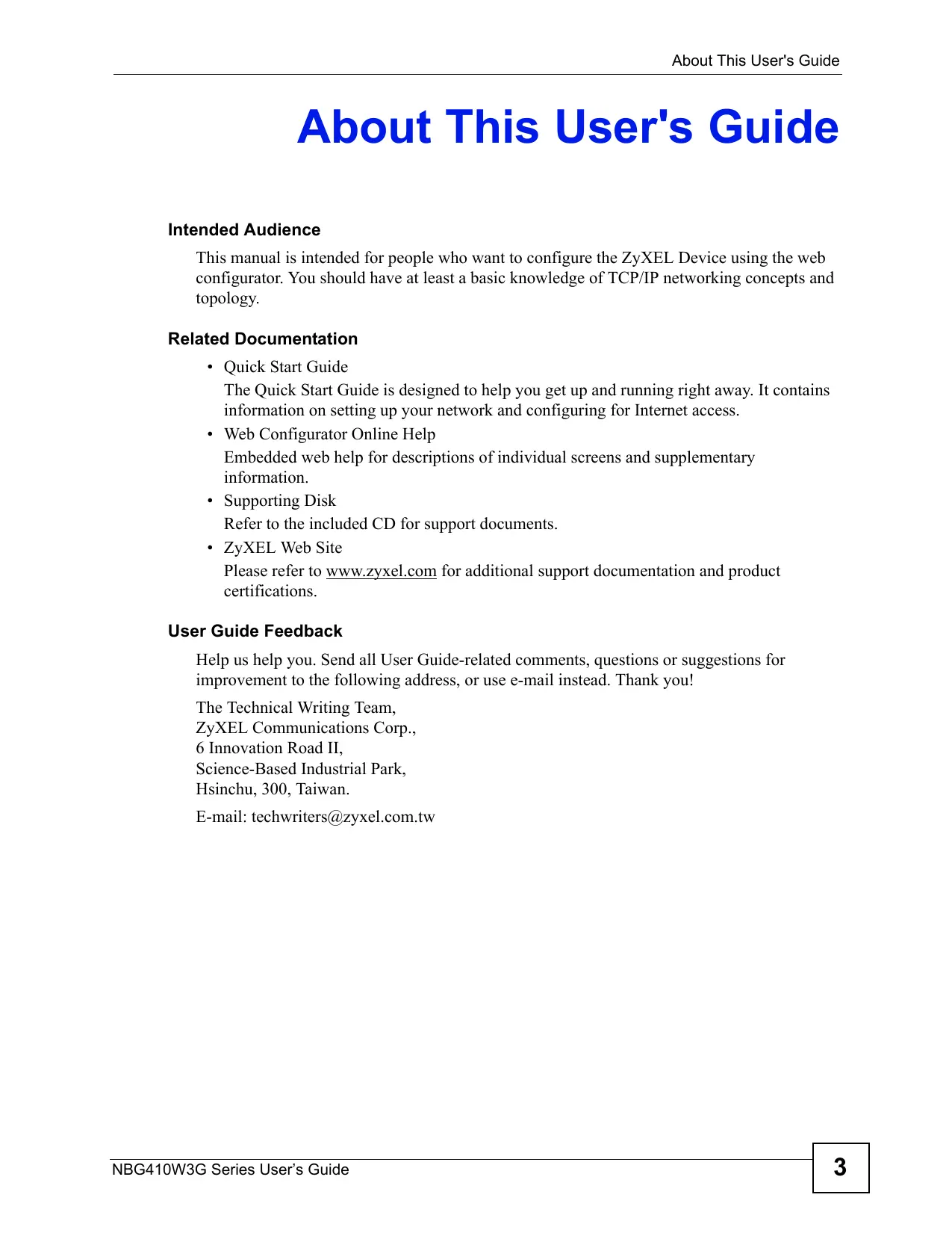
1.2.1 3G WAN Application
With an activated, correctly inserted 3G SIM card and/or 3G USB dongle you can use the ZyXEL Device to wirelessly access the Internet via a 3G base station. See Section 6.9 on page 126 for more information about 3G.
With both the primary WAN (physical WAN port) and 3G connections enabled, you can set one of the WAN connections as a backup.
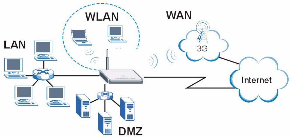
Figure 1 3G WAN Application
1.2.2 Secure Broadband Internet Access via Cable or DSL Modem
For Internet access, connect the WAN Ethernet port to your existing Internet access gateway (company network, or your cable or DSL modem for example). Connect computers or servers to the LAN or DMZ ports for shared Internet access.
The ZyXEL Device guarantees not only high speed Internet access, but secure internal network protection and traffic management as well.
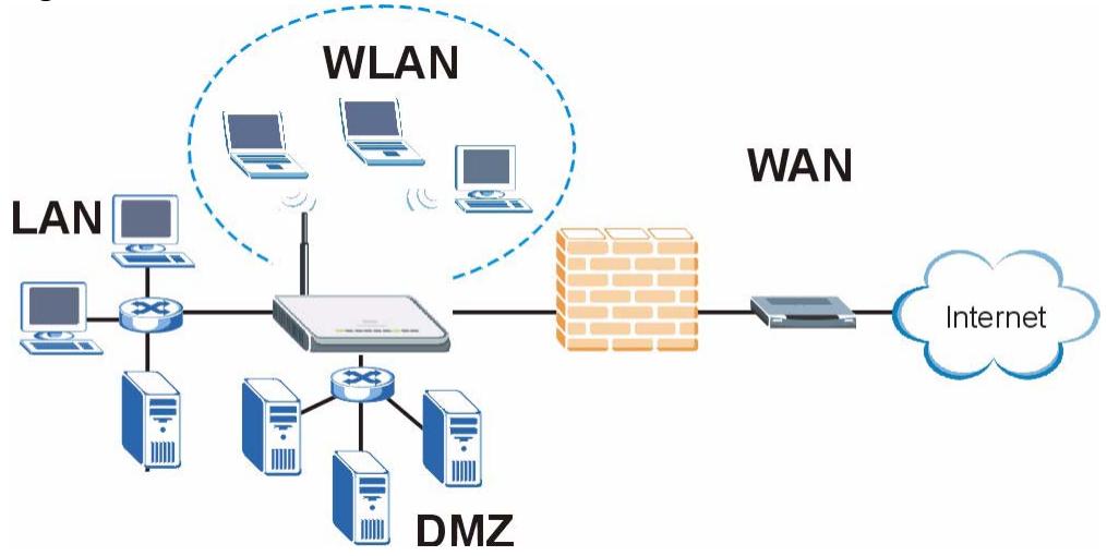
Figure 2 Secure Internet Access via Cable or DSL Modem
1.3 Ways to Manage the ZyXEL Device
Use any of the following methods to manage the ZyXEL Device.
- Web Configurator. This is recommended for everyday management of the ZyXEL Device using a (supported) web browser.
- Command Line Interface. Line commands are mostly used for troubleshooting by service engineers.
- FTP for firmware upgrades and configuration backup/restore.
1.4 Configuring Your ZyXEL Device's Security Features
Your ZyXEL Device comes with a variety of security features. This section summarizes these features and provides links to sections in the User's Guide to configure security settings on your ZyXEL Device. Follow the suggestions below to improve security on your ZyXEL Device and network.
1.4.1 Control Access to Your Device
Ensure only people with permission can access your ZyXEL Device.
- Control physical access by locating devices in secure areas, such as locked rooms. Most ZyXEL Devices have a reset button. If an unauthorized person has access to the reset button, they can then reset the device's password to its default password, log in and reconfigure its settings.
- Change any default passwords on the ZyXEL Device, such as the password used for accessing the ZyXEL Device's web configurator (if it has a web configurator). Use a password with a combination of letters and numbers and change your password regularly. Write down the password and put it in a safe place.
- Avoid setting a long timeout period before the ZyXEL Device's web configurator automatically times out. A short timeout reduces the risk of unauthorized person accessing the web configurator while it is left idle.
See Chapter 20 on page 325 for instructions on changing your password and setting the timeout period.
- Configure remote management to control who can manage your ZyXEL Device. See Section 15.1 on page 259 for more information. If you enable remote management, ensure you have enabled remote management only on the IP addresses, services or interfaces you intended and that other remote management settings are disabled.
1.4.2 Wireless Security
Wireless devices are especially vulnerable to attack. If your ZyXEL Device has a wireless function, take the following measures to improve wireless security.
- Enable wireless security on your ZyXEL Device. Choose the most secure encryption method that all devices on your network support. If you have a RADIUS server, enable IEEE 802.1x or WPA(2) user identification on your network so users must log in. This method is more common in business environments.
- Hide your wireless network name (SSID). TheSSID can be regularly broadcast and unauthorized users may use this information to access your network.
- Enable the MAC filter to allow only trusted users to access your wireless network or deny unwanted users access based on their MAC address.
See Section 8.2 on page 148 for directions on these wireless security measures.
1.4.3 Firewall
See Section 9.1 on page 167 for more information on the following security measures
-
Ensure the firewall is turned on. Traffic initiated from your WAN is blocked by default.
-
Set the firewall to blockICMPrequests.
- Enable do not respond to requests for unauthorized services.
- If you have a backup gateway (for example, backup Internet access) on your network, disable the Bypass Triangle Routes feature and enable IP Alias to put your backup gateway on a different subnet.
- Avoid raising the maximum number of NAT sessions per host unnecessarily as it increases the possibility of unauthorized connections, such as connections caused by a computer virus.
1.4.4 NAT
- Enable NAT (Network Address Translation) to make devices on your network "invisible" to those outside your network (unless you configure port-forwarding rules for them).
- Applications such as games or file-sharing can be configured so they are visible from other networks by using port-forwarding. Ensure only applications you want are configured to port-forward.
See Section 12.1 on page 225 for instructions on these measures.
1.4.5 UPnP
- Disable UPnP (Universal Plug and Play) unless you specifically want applications (for example, games or file-sharing applications) on your network to pass through your firewall unchecked.
See Section 16.1 on page 281 for instructions on this measure.
1.5 Maintaining Your ZyXEL Device
Do the following things regularly to keep your ZyXEL Device running.
- Check the ZyXEL website (www.zyxel.com.tw) regularly for new firmware for your ZyXEL Device.

Ensure you download the correct firmware for your model.
- Back up the configuration (and make sure you know how to restore it). Restoring an earlier working configuration may be useful if the device becomes unstable or even crashes. If you forget your password, you will have to reset the ZyXEL Device to its factory default settings. If you backed up an earlier configuration file, you would not have to totally reconfigure the ZyXEL Device. You could simply restore your last configuration.
1.5.1 Front Panel Lights

Figure 3 Front Panel
The following tables describe the lights. Table 1 describes the light features in NBG410W3G, and Table 2 describes the light features in NBG412W3G.
Table 1 NBG410W3G Front Panel Lights
| LED | ICONS | COLOR | STATUS | DESCRIPTION |
| POWER | Off | The ZyXEL Device is turned off. | ||
| Green | On | The ZyXEL Device is ready and running. | ||
| Flashing | The ZyXEL Device is restarting. | |||
| Red | On | The power to the ZyXEL Device is too low. | ||
| LAN/DMZ 10/100 | Off | The LAN/DMZ is not connected. | ||
| Green | On | The ZyXEL Device has a successful 10Mbps Ethernet connection. | ||
| Flashing | The 10M LAN is sending or receiving packets. | |||
| Orange | On | The ZyXEL Device has a successful 100Mbps Ethernet connection. | ||
| Flashing | The 100M LAN is sending or receiving packets. | |||
| WAN | Off | The WAN connection is not ready, or has failed. | ||
| Green | On | The ZyXEL Device has a successful 10Mbps WAN connection. | ||
| Flashing | The 10M WAN is sending or receiving packets. | |||
| Orange | On | The ZyXEL Device has a successful 100Mbps WAN connection. | ||
| Flashing | The 100M WAN is sending or receiving packets. | |||
| Wi-Fi | Off | The wireless connection through the built-in Wi-Fi card is not ready, or has failed. | ||
| On | The wireless LAN through the built-in wireless LAN card is ready. | |||
| Flashing | The wireless LAN through the built-in wireless LAN card is sending or receiving packets. | |||
| 3G OPERATION | 3G | Green | On | The ZyXEL Device has a successful 3G connection. |
| Flashing | The ZyXEL Device has detected an available 3G network, but has not yet connected to it. | |||
| Blue | On | The ZyXEL Device has a successful 3.5G connection | ||
| Flashing | The ZyXEL Device has detected an available 3.5G network, but has not yet connected to it. | |||
| Orange | On | The ZyXEL Device has a successful 2G or 2.5G connection | ||
| Flashing | The ZyXEL Device has detected an available 2G or 2.5G network, but has not yet connected to it. | |||
| Off | One (or more) of the following has occurred. • The 3G function is not activated. • The ZyXEL Device is not registered with a 3G network. • The ZyXEL Device is using a 3G USB dongle for 3G connection. | |||
| 3G SIGNAL STRENGTH | Green | On | The 3G signal is strong. | |
| Yellow | The 3G signal is moderate. | |||
| Red | The 3G signal is weak. | |||
| Off | If the 3G OPERATION LED is off, there is no 3G connection, or the ZyXEL Device is using a 3G USB dongle for a 3G connection. If the 3G OPERATION LED is not off, no 3G signal is detected. |
Table 2 NBG412W3G Front Panel Lights
| LED | ICONS | COLOR | STATUS | DESCRIPTION |
| POWER | Off | The ZyXEL Device is turned off. | ||
| Green | On | The ZyXEL Device is ready and running. | ||
| Flashing | The ZyXEL Device is restarting. | |||
| Red | On | The power to the ZyXEL Device is too low. | ||
| LAN/DMZ 10/100 | Off | The LAN/DMZ is not connected. | ||
| Green | On | The ZyXEL Device has a successful 10Mbps Ethernet connection. | ||
| Flashing | The 10M LAN is sending or receiving packets. | |||
| Orange | On | The ZyXEL Device has a successful 100Mbps Ethernet connection. | ||
| Flashing | The 100M LAN is sending or receiving packets. | |||
| WAN | Off | The WAN connection is not ready, or has failed. | ||
| Green | On | The ZyXEL Device has a successful 10Mbps WAN connection. | ||
| Flashing | The 10M WAN is sending or receiving packets. | |||
| Orange | On | The ZyXEL Device has a successful 100Mbps WAN connection. | ||
| Flashing | The 100M WAN is sending or receiving packets. | |||
| Wi-Fi | i | Green | Off | The wireless connection through the built-in Wi-Fi card is not ready, or has failed. |
| On | The wireless LAN through the built-in wireless LAN card is ready. | |||
| Flashing | The wireless LAN through the built-in wireless LAN card is sending or receiving packets. | |||
| 3G MODE | 3G | Green | On | The 3G function is activated. |
| Off | The 3G function is not activated. | |||
| 3G LINK | T | Green | On | The ZyXEL Device has a successful 3G connection. |
| Off | There is no 3G connection. |
Introducing the Web Configurator
This chapter describes how to access the ZyXEL Device web configurator and provides an overview of its screens.
2.1 Web Configurator Overview
The web configurator is an HTML-based management interface that allows easy ZyXEL Device setup and management via Internet browser. Use Internet Explorer 6.0 and later or Netscape Navigator 7.0 and later versions. The recommended screen resolution is 1024 by 768 pixels.
In order to use the web configurator you need to allow:
- Web browser pop-up windows from your device. Web pop-up blocking is enabled by default in Windows XP SP (Service Pack) 2.
- JavaScripts (enabled by default).
- Java permissions (enabled by default).
See Appendix A on page 353 if you want to make sure these functions are allowed in Internet Explorer or Netscape Navigator.
2.2 Accessing the ZyXEL Device Web Configurator
1 Make sure your ZyXEL Device hardware is properly connected and prepare your computer/computer network to connect to the ZyXEL Device (refer to the Quick Start Guide).
2 Launch your web browser.
3 Type "192.168.1.1" as the URL.
4 Type "1234" (default) as the password and click Login. In some versions, the default password appears automatically - if this is the case, click Login.
Figure 4 Login Screen
5 You should see a screen asking you to change your password (highly recommended) as shown next. Type a new password (and retype it to confirm) and click Apply or click Ignore.
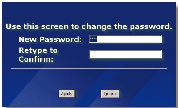
Figure 5 Change Password Screen
6 Click Apply in the Replace Certificate screen to create a certificate using your ZyXEL Device's MAC address that will be specific to this device.

If you do not replace the default certificate here or in the CERTIFICATES screen, this screen displays every time you access the web configurator.
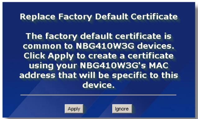
Figure 6 Replace Certificate Screen
7 You should now see the HOME screen (see Figure 9 on page 47).

The management session automatically times out when the time period set in the Administrator Inactivity Timer field expires (default five minutes). Simply log back into the ZyXEL Device if this happens to you.
2.3 Resetting the ZyXEL Device
If you forget your password or cannot access the web configurator, you will need to reload the factory-default configuration file or use the RESET button on the back of the ZyXEL Device. Uploading this configuration file replaces the current configuration file with the factory-default configuration file. This means that you will lose all configurations that you had previously and the speed of the console port will be reset to the default of 9600bps with 8 data bit, no parity, one stop bit and flow control set to none. The password will be reset to 1234, also.
2.3.1 Procedure To Use The Reset Button
Make sure the POWER LED is on (not blinking) before you begin this procedure.
1 Press the RESET button for ten seconds, and then release it. If the POWER LED begins to blink, the defaults have been restored and the ZyXEL Device restarts. Otherwise, go to step 2.
2 Turn the ZyXEL Device off.
3 While pressing the RESET button, turn the ZyXEL Device on.
4 Continue to hold the RESET button. The POWER LED will begin to blink and flicker very quickly after about 20 seconds. This indicates that the defaults have been restored and the ZyXEL Device is now restarting.
5 Release the RESET button and wait for the ZyXEL Device to finish restarting.
1 Download the default configuration file from the ZyXEL FTP site, unzip it and save it in a folder.
2 Turn off the ZyXEL Device, begin a terminal emulation software session and turn on the ZyXEL Device again. When you see the message "Press Any key to enter Debug Mode within 3 seconds", press any key to enter debug mode.
3 Enter "y" at the prompt below to go into debug mode.
4 Enter "atlc" after "Enter Debug Mode" message.
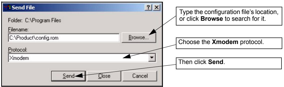
5 Wait for "Starting XMODem upload" message before activating Xmodem upload on your terminal. This is an example Xmodem configuration upload using HyperTerminal.
Figure 7 Example Xmodem Upload
6 After successful firmware upload, enter "atgo" to restart the router.
2.4 Navigating the ZyXEL Device Web Configurator
The following summarizes how to navigate the web configurator from the HOME screen.
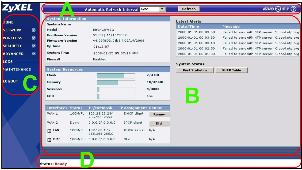
Figure 8 HOME Screen
As illustrated above, the main screen is divided into these parts:
A - title bar
B - main window
C - navigation panel
- D - status bar
2.4.1 Title Bar
The title bar provides some icons in the upper right corner.
The icons provide the following functions.
Table 3 Title Bar: Web Configurator Icons
| ICON | DESCRIPTION |
| WIZARD | Wizard Click this icon to open one of the web configurator wizards. See Chapter 3 on page 59 for more information. |
| HELP | Help Click this icon to open the help page for the current screen. |
2.4.2 Main Window
The main window shows the screen you select in the navigation panel. It is discussed in more detail in the rest of this document.
Right after you log in, the HOME screen is displayed.
2.4.3 HOME Screen
This screen displays general status information about the ZyXEL Device.
WAN 2 refers to the 3G feature on the supported ZyXEL Device.
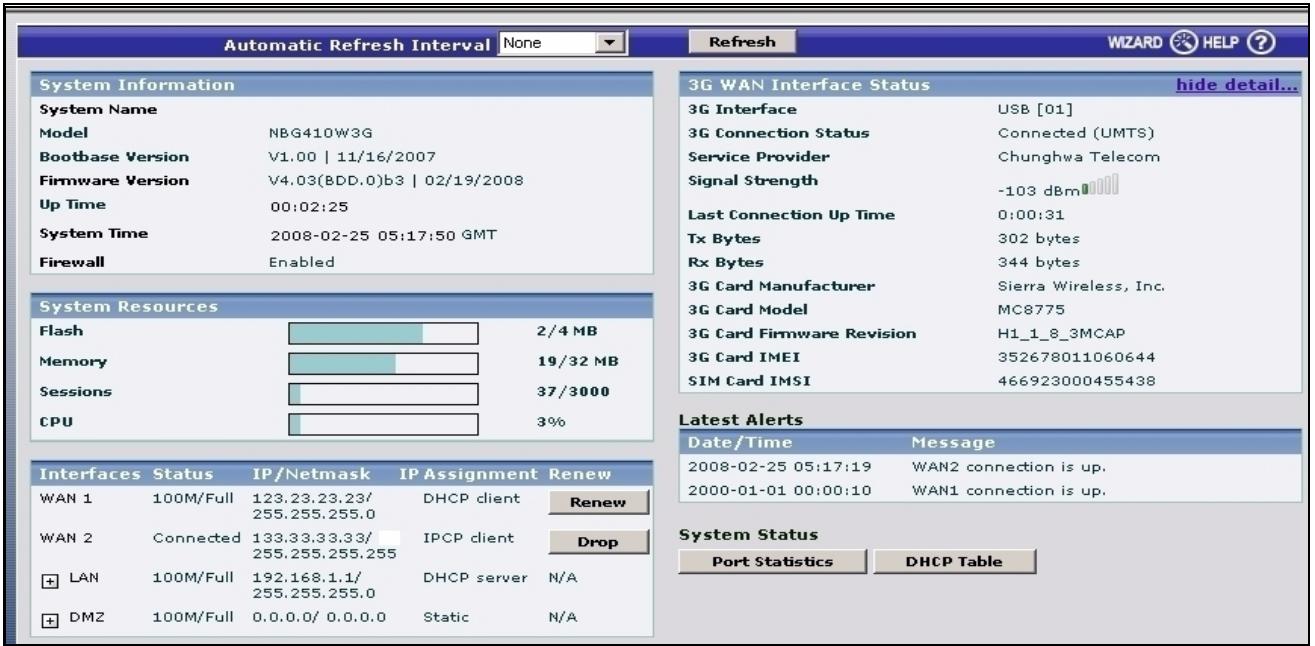
Figure 9 Web Configurator HOME Screen
The following table describes the labels in this screen.
Table 4 Web Configurator HOME Screen
| LABEL | DESCRIPTION |
| Automatic Refresh Interval | Select a number of seconds or None from the drop-down list box to update all screen statistics automatically at the end of every time interval or to not update the screen statistics. |
| Refresh | Click this button to update the status screen statistics immediately. |
| System Information | |
| System Name | This is the System Name you enter in the MAINTENANCE > General screen. It is for identification purposes. Click the field label to go to the screen where you can specify a name for this ZyXEL Device. |
| Model | This is the model name of your ZyXEL Device. |
| Bootbase Version | This is the bootbase version and the date created. |
| Firmware Version | This is the ZyNOS firmware version and the date created. ZyNOS is ZyXEL's proprietary Network Operating System design. Click the field label to go to the screen where you can upload a new firmware file. |
| Up Time | This field displays how long the ZyXEL Device has been running since it last started up. The ZyXEL Device starts up when you turn it on, when you restart it (MAINTENANCE > Restart), or when you reset it (see Section 2.3 on page 45). |
| System Time | This field displays your ZyXEL Device's present date (in yyyy-mm-dd format) and time (in hh:mm:ss format) along with the difference from the Greenwich Mean Time (GMT) zone. The difference from GMT is based on the time zone. It is also adjusted for Daylight Saving Time if you set the ZyXEL Device to use it. Click the field label to go to the screen where you can modify the ZyXEL Device's date and time settings. |
| Firewall | This displays whether or not the ZyXEL Device's firewall is activated. Click the field label to go to the screen where you can turn the firewall on or off. |
| System Resources | |
| Flash | The first number shows how many megabytes of the flash the ZyXEL Device is using. |
| Memory | The first number shows how many megabytes of the heap memory the ZyXEL Device is using. Heap memory refers to the memory that is not used by ZyNOS (ZyXEL Network Operating System) and is thus available for running processes like NAT and the firewall. The second number shows the ZyXEL Device's total heap memory (in megabytes). The bar displays what percent of the ZyXEL Device's heap memory is in use. The bar turns from green to red when the maximum is being approached. |
| Sessions | The first number shows how many sessions are currently open on the ZyXEL Device. This includes all sessions that are currently traversing the ZyXEL Device, terminating at the ZyXEL Device or Initiated from the ZyXEL Device The second number is the maximum number of sessions that can be open at one time. The bar displays what percent of the maximum number of sessions is in use. The bar turns from green to red when the maximum is being approached. |
| CPU | This field displays what percentage of the ZyXEL Device's processing ability is currently used. When this percentage is close to 100%, the ZyXEL Device is running at full load, and the throughput is not going to improve anymore. If you want some applications to have more throughput, you should turn off other applications. |
| Interfaces | This is the port type. Click "+" to expand or "-" to collapse the IP alias drop-down lists. Hold your cursor over an interface's label to display the interface's MAC address. Click an interface's label to go to the screen where you can configure settings for that interface. |
| Status | For the LAN and DMZ ports, this displays the port speed and duplex setting. Ethernet port connections can be in half-duplex or full-duplex mode. Full-duplex refers to a device's ability to send and receive simultaneously, while half-duplex indicates that traffic can flow in only one direction at a time. The Ethernet port must use the same speed or duplex mode setting as the peer Ethernet port in order to connect.For the WAN 1 port, it displays the port speed and duplex setting if you're using Ethernet encapsulation or the remote node name for a PPP connection and Down (line is down or not connected), Idle (line (ppp) idle), Dial (starting to trigger a call) or Drop (dropping a call) if you're using PPPoE encapsulation.For the WAN 2 interface, it displays Connected when the 3G connection is up, Connecting when the 3G card is trying to connect to a network but has not received a response from the base station, Ready to Connect when the 3G connection is idle, Initializing when the ZyXEL Device is configuring the 3G card with AT commands, Disconnecting when the ZyXEL Device is dropping the 3G connection or Down when the 3G connection is down. |
| IP/Netmask | This shows the port's IP address and subnet mask. |
| IP Assignment | For the WAN, if the ZyXEL Device gets its IP address automatically from an ISP, this displays DHCP client when you're using Ethernet encapsulation and IPCP Client when you're using PPPoE or PPTP encapsulation. Static displays if the WAN port is using a manually entered static (fixed) IP address.For the LAN or DMZ, DHCP server displays when the ZyXEL Device is set to automatically give IP address information to the computers connected to the LAN. DHCP relay displays when the ZyXEL Device is set to forward IP address assignment requests to another DHCP server. Static displays if the LAN port is using a manually entered static (fixed) IP address. In this case, you must have another DHCP server on your LAN, or else the computers must be manually configured. |
| Renew | If you are using Ethernet encapsulation and the WAN port is configured to get the IP address automatically from the ISP, click Renew to release the WAN port's dynamically assigned IP address and get the IP address afresh. Click Dial to dial up the PPTP, PPPoE or 3G WAN connection. Click Drop to disconnect the PPTP, PPPoE or 3G WAN connection. |
| 3G WAN Interface Status | The fields below display when a 3G card is inserted and WAN 2 is enabled. |
| show detail.../hide detail... | Click show detail... to see more information about the 3G connection and 3G card. Click hide detail... to display less information about the 3G connection and 3G card. |
| 3G Connection Status | This displays Down when the 3G connection is down or not activated.This displays Initializing when the ZyXEL Device is configuring the 3G card with AT commands.This displays Ready to Connect when the 3G connection is idle before the ZyXEL Device triggers a call.This displays Connecting when the 3G card is trying to connect to a network but has not received a response from the base station.This displays Connected when the 3G connection is up.This displays Disconnecting when the ZyXEL Device is dropping the 3G connection.This field also displays the type of the network to which the ZyXEL Device is connected. The network type varies depending on the 3G card you inserted and could be UMTS, HSDPA, GPRS or EDGE when you insert a GSM 3G card, or 1xRTT, EVDO Rev.0 or EVDO Rev.A when you insert a CDMA 3G card. |
| Service Provider | This displays the name of your network service provider or Limited Service when the signal strength is too low or the ISP is limiting your access. |
| Roaming Network | This field is available only when you insert a 3G card that supports the roaming feature. This displays whether the card is able to connect to other ISPs' base stations. |
| Dormant State | This field is available only when you insert a 3G card that supports the dormant state. This displays whether the card is in dormant state. When there is no data transmitting, a card does not send a radio signal and is in dormant state to reduce bandwidth usage. |
| Signal Strength | This displays the signal strength of the wireless network in dBm. The status bar shows the strength of the signal. The signal strength mainly depends on the antenna output power and the distance between your ZyXEL Device and the service provider's base station. You can see a signal strength indication even when the ZyXEL Device does not have a 3G connection (because the signal is still there even when the ZyXEL Device is not using it). |
| Last Connection Up Time | This displays how long the 3G connection has been up. |
| Tx Bytes | This displays the total number of data frames transmitted. |
| Rx Bytes | This displays the total number of data frames received. |
| 3G Card Manufacturer | This displays the manufacturer of your 3G card. |
| 3G Card Model | This displays the model name of your 3G card. |
| 3G Card Firmware Revision | This displays the version of the firmware currently used in the 3G card. |
| 3G Card IMEI | This field is available only when you insert a GSM (Global System for Mobile Communications) or UMTS (Universal Mobile Telecommunications System) 3G card. This displays the International Mobile Equipment Identity (IMEI) which is the serial number of the GSM or UMTS 3G wireless card. The IMEI is a unique 15-digit number used to identify a mobile device. |
| SIM Card IMSI | This field is available only when you insert a GSM or UMTS 3G card. This displays the International Mobile Subscriber Identity (IMSI) stored in the SIM (Subscriber Identity Module) card. The SIM card is installed in a mobile device and used for authenticating a customer to the carrier network. The IMSI is a unique 15-digit number used to identify a user on a network. |
| 3G Card ESN | This field is available only when you insert a CDMA (Code Division Multiple Access) 3G card. This shows the ESN (Electronic Serial Number) of the inserted CDMA 3G card. The ESN is the serial number of a CDMA 3G card and is similar to the IMEI on a GSM or UMTS 3G card. |
| Enter PIN code again | If the PIN code you specified in the 3G (WAN 2) screen is not the right one for the card you inserted, this field displays allowing you to enter the correct PIN code. Enter the PIN code (four to eight digits) for the inserted 3G card. |
| Apply | Click Apply to save the correct PIN code and replace the one you specified in the 3G (WAN 2) screen. |
| PUK Code | If you enter the PIN code incorrectly three times, the SIM card will be blocked by your ISP and you cannot use the account to access the Internet. You should get the PUK (Personal Unblocking Key) code (four to eight digits) from your ISP. Enter the PUK code to enable the SIM card. If an incorrect PUK code is entered 10 times, the SIM card will be disabled permanently. You then need to contact your ISP for a new SIM card. |
| New PIN Code | Configure a PIN code for the SIM card. You can specify any four to eight digits to have a new PIN code or enter the previous PIN code. |
| Confirm New PIN Code | Enter the PIN code again for confirmation. |
| Apply | Click Apply to save your changes in this section. |
| Reset budget counters, resume budget control | This field displays if you have enabled budget control but insert a 3G card with a different user account from the one for which you configured budget control. Select this option to have the ZyXEL Device do budget calculation starting from 0 but use the previous settings. |
| Resume budget control | This field displays if you have enabled budget control but insert a 3G card with a different user account from the one for which you configured budget control. Select this option to have the ZyXEL Device keep the existing statistics and continue counting. |
| Disable budget control | This field displays if you have enabled budget control but insert a 3G card with a different user account from the one for which you configured budget control. Select this option to disable budget control. If you want to enable and configure new budget control settings for the new user account, go to the 3G (WAN 2) screen. The ZyXEL Device keeps the existing statistics if you do not change the budget control settings. You could reinsert the original card and enable budget control to have the ZyXEL Device continue counting the budget control statistics. |
| Apply | Click Apply to save your changes in this section. |
| Enter modem unlock code | This field only displays when you insert a 3G card and the internal modem on the 3G card is blocked. Enter a key to enable the internal modem on your 3G card. By default, the key is the last four digits of your phone number used to dial up the 3G connection. Otherwise, you need to get the key from your service provider. |
| Apply | Click Apply to save your changes in this section. |
| Remaining Time Budget | This field is available only when you enable budget control in the 3G (WAN 2) screen. This shows the amount of time (in hours and minutes) the 3G connection can still be used before the ZyXEL Device takes the actions you specified in the 3G (WAN 2) screen. |
| Remaining Data Budget | This field is available only when you enable budget control in the Network > WAN > 3G (WAN 2) screen. This shows how much data (in bytes) can still be transmitted through the 3G connection before the ZyXEL Device takes the actions you specified in the 3G (WAN 2) screen. Note: The budget counters will not be reset when you restore the factory defaults. The budget counters are saved to the flash every hour or when the 3G connection is dropped. If you restart the ZyXEL Device within one hour, any change in the counters will not be saved. |
| Reset time and data budget counters | This button is available only when you enable budget control in the 3G (WAN 2) screen. Click this button to reset the time and data budgets. The count starts over with the 3G connection's full configured monthly time and data budgets. This does not affect the normal monthly budget restart. |
| Latest Alerts | This table displays the five most recent alerts recorded by the ZyXEL Device. You can see more information in the View Log screen, such as the source and destination IP addresses and port numbers of the incoming packets. |
| Date/Time | This is the date and time the alert was recorded. |
| Message | This is the reason for the alert. |
| System Status | |
| Port Statistics | Click Port Statistics to see router performance statistics such as the number of packets sent and number of packets received for each port. |
| DHCP Table | Click DHCP Table to show current DHCP client information. |
| Bandwidth | Click Bandwidth to view the ZyXEL Device's bandwidth usage and allotments. |
2.4.4 Navigation Panel
After you enter the password, use the sub-menus on the navigation panel to configure ZyXEL Device features.
The following table describes the sub-menus.
Table 5 Screens Summary
| LINK | TAB | FUNCTION |
| HOME | This screen shows the ZyXEL Device's general device and network status information. Use this screen to access the wizards, statistics and DHCP table. | |
| NETWORK | ||
| LAN | LAN | Use this screen to configure LAN DHCP and TCP/IP settings. |
| Static DHCP | Use this screen to assign fixed IP addresses on the LAN. | |
| IP Alias | Use this screen to partition your LAN interface into subnets. | |
| Port Roles | Use this screen to change the LAN/DMZ port roles. | |
| WAN | General | This screen allows you to configure operation mode, route priority and connection test. |
| WAN1 | Use this screen to configure the WAN1 connection for Internet access. | |
| 3G (WAN2) | Use this screen to configure the WAN2 connection for Internet access. | |
| Traffic Redirect | Use this screen to configure your traffic redirect properties and parameters. | |
| DMZ | DMZ | Use this screen to configure your DMZ connection. |
| Static DHCP | Use this screen to assign fixed IP addresses on the DMZ. | |
| IP Alias | Use this screen to partition your DMZ interface into subnets. | |
| Port Roles | Use this screen to change the LAN/DMZ port roles on the ZyXEL Device. | |
| WIRELESS | ||
| 3G (WAN2) | 3G (WAN2) | Use this screen to configure the WAN2 connection for Internet access. |
| Wi-Fi | Wireless Card | Use this screen to configure the wireless LAN settings. |
| Security | Use this screen to configure the Wi-Fi security settings. | |
| MAC Filter | Use this screen to change MAC filter settings on the ZyXEL Device | |
| SECURITY | ||
| FIREWALL | Default Rule | Use this screen to activate/deactivate the firewall and the direction of network traffic to which to apply the rule |
| Rule Summary | This screen shows a summary of the firewall rules, and allows you to edit/add a firewall rule. | |
| Anti-Probing | Use this screen to change your anti-probing settings. | |
| Threshold | Use this screen to configure the threshold for DoS attacks. | |
| Service | Use this screen to configure custom services. | |
| CERTIFICATES | My Certificates | Use this screen to view a summary list of certificates and manage certificates and certification requests. |
| Trusted CAs | Use this screen to view and manage the list of the trusted CAs. | |
| Trusted Remote Hosts | Use this screen to view and manage the certificates belonging to the trusted remote hosts. | |
| Directory Servers | Use this screen to view and manage the list of the directory servers. | |
| AUTH SERVER | Local User Database | Use this screen to configure the local user account(s) on the ZyXEL Device. |
| RADIUS | Configure this screen to use an external server to authenticate wireless users. | |
| ADVANCED | ||
| NAT | NAT Overview | Use this screen to enable NAT. |
| Address Mapping | Use this screen to configure network address translation mapping rules. | |
| Port Forwarding | Use this screen to configure servers behind the ZyXEL Device. | |
| Port Triggering | Use this screen to change your ZyXEL Device's port triggering settings. | |
| STATIC ROUTE | IP Static Route | Use this screen to configure IP static routes. |
| DNS | System | Use this screen to configure the address and name server records. |
| Cache | Use this screen to configure the DNS resolution cache. | |
| DHCP | Use this screen to configure LAN/DMZ DNS information. | |
| DDNS | Use this screen to set up dynamic DNS. | |
| REMOTE MGMT | WWW | Use this screen to configure through which interface(s) and from which IP address(es) users can use HTTPS or HTTP to manage the ZyxEL Device. |
| SSH | Use this screen to configure through which interface(s) and from which IP address(es) users can use Secure Shell to manage the ZyxEL Device. | |
| TELNET | Use this screen to configure through which interface(s) and from which IP address(es) users can use Telnet to manage the ZyxEL Device. | |
| FTP | Use this screen to configure through which interface(s) and from which IP address(es) users can use FTP to access the ZyxEL Device. | |
| SNMP | Use this screen to configure your ZyxEL Device's settings for Simple Network Management Protocol management. | |
| DNS | Use this screen to configure through which interface(s) and from which IP address(es) users can send DNS queries to the ZyxEL Device. | |
| CNM | Use this screen to configure and allow your ZyxEL Device to be managed by the Vantage CNM server. | |
| UPnP | UPnP | Use this screen to enable UPnP on the ZyxEL Device. |
| Ports | Use this screen to view the NAT port mapping rules that UPnP creates on the ZyxEL Device. | |
| Custom APP | Custom APP | Use this screen to specify port numbers for the ZyxEL Device to monitor for FTP, HTTP, SMTP, POP3, H323, and SIP traffic. |
| ALG | ALG | Use this screen to allow certain applications to pass through the ZyxEL Device. |
| LOGS | View Log | Use this screen to view the logs for the categories that you selected. |
| Log Settings | Use this screen to change your ZyxEL Device's log settings. | |
| Reports | Use this screen to have the ZyxEL Device record and display the network usage reports. | |
| MAINTENANCE | General | This screen contains administrative. |
| Password | Use this screen to change your password. | |
| Time and Date | Use this screen to change your ZyxEL Device's time and date. | |
| F/W Upload | Use this screen to upload firmware to your ZyxEL Device | |
| Backup & Restore | Use this screen to backup and restore the configuration or reset the factory defaults to your ZyxEL Device. | |
| Restart | This screen allows you to reboot the ZyxEL Device without turning the power off. | |
| LOGOUT | Click this label to exit the web configurator. | |
2.4.5 Port Statistics
Click Port Statistics in the HOME screen. Read-only information here includes port status and packet specific statistics. The Automatic Refresh Interval field is configurable.
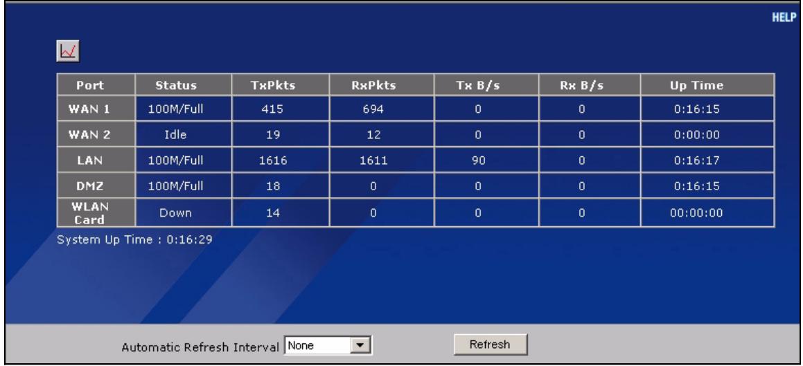
Figure 10 HOME > Show Statistics
The following table describes the labels in this screen.
Table 6 HOME > Show Statistics
| LABEL | DESCRIPTION |
| Click the icon to display the chart of throughput statistics. | |
| Port | These are the ZyXEL Device's interfaces. |
| Status | For the WAN interface(s), this displays the port speed and duplex setting if you're using Ethernet encapsulation or the remote node name for a PPP connection and Down (line is down or not connected), Idle (line (ppp) idle), Dial (starting to trigger a call) or Drop (dropping a call) if you're using PPPoE encapsulation. For the LAN or DMZ ports, this displays the port speed and duplex setting. For the Wi-Fi card, this displays the transmission rate when Wi-Fi is enabled or Down when Wi-Fi is disabled. |
| TxPkts | This is the number of transmitted packets on this port. |
| RxPkts | This is the number of received packets on this port. |
| Tx B/s | This displays the transmission speed in bytes per second on this port. |
| Rx B/s | This displays the reception speed in bytes per second on this port. |
| Up Time | This is the total amount of time the line has been up. |
| System Up Time | This is the total time the ZyXEL Device has been on. |
| Automatic Refresh Interval | Select a number of seconds or None from the drop-down list box to update all screen statistics automatically at the end of every time interval or to not update the screen statistics. |
| Refresh | Click this button to update the screen's statistics immediately. |
2.4.6 Show Statistics: Line Chart
Click the icon in the Show Statistics screen. This screen shows you a line chart of each port's throughput statistics.
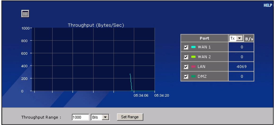
Figure 11 HOME > Show Statistics > Line Chart
The following table describes the labels in this screen.
Table 7 HOME > Show Statistics > Line Chart
| LABEL | DESCRIPTION |
| Click the icon to go back to the Show Statistics screen. | |
| Port | Select the check box(es) to display the throughput statistics of the corresponding interface(s). |
| B/s | Specify the direction of the traffic for which you want to show throughput statistics in this table. Select Tx to display transmitted traffic throughput statistics and the amount of traffic (in bytes). Select Rx to display received traffic throughput statistics and the amount of traffic (in bytes). |
| Throughput Range | Set the range of the throughput (in B/s, KB/s or MB/s) to display. Click Set Range to save this setting back to the ZyXEL Device. |
2.4.7 DHCP Table Screen
DHCP (Dynamic Host Configuration Protocol, RFC 2131 and RFC 2132) allows individual clients to obtain TCP/IP configuration at start-up from a server. You can configure the ZyXEL Device as a DHCP server or disable it. When configured as a server, the ZyXEL Device provides the TCP/IP configuration for the clients. If DHCP service is disabled, you must have another DHCP server on your LAN, or else the computer must be manually configured.
Click Show DHCP Table in the HOME screen. Read-only information here relates to your DHCP status. The DHCP table shows current DHCP client information (including IP Address, Host Name and MAC Address) of all network clients using the ZyXEL Device's DHCP server.
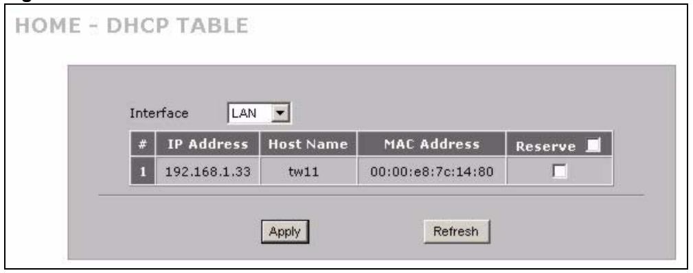
Figure 12 HOME > DHCP Table
The following table describes the labels in this screen.
Table 8 HOME > DHCP Table
| LABEL | DESCRIPTION |
| Interface | Select LAN or DMZ to show the current DHCP client information for the specified interface. |
| # | This is the index number of the host computer. |
| IP Address | This field displays the IP address relative to the # field listed above. |
| Host Name | This field displays the computer host name. |
| MAC Address | The MAC (Media Access Control) or Ethernet address on a LAN (Local Area Network) is unique to your computer (six pairs of hexadecimal notation). A network interface card such as an Ethernet adapter has a hardwired address that is assigned at the factory. This address follows an industry standard that ensures no other adapter has a similar address. |
| Reserve | Select the check box in the heading row to automatically select all check boxes or select the check box(es) in each entry to have the ZyXEL Device always assign the selected entry(ies)'s IP address(es) to the corresponding MAC address(es) (and host name(s)). You can select up to 128 entries in this table. After you click Apply, the MAC address and IP address also display in the corresponding LAN or DMZ Static DHCP screen (where you can edit them). |
| Refresh | Click Refresh to reload the DHCP table. |
Wizard Setup
This chapter provides information on the Wizard Setup screens in the web configurator.
3.1 Wizard Setup Overview
The web configurator's setup wizards help you configure Internet connection settings.
In the HOME screen, click the wizard icon WIZARD to open the Wizard Setup Welcome screen. The following summarizes the wizards you can select:
- Internet Access Setup
Click this link to open a wizard to set up an Internet connection for WAN 1 (the WAN port) on the ZyXEL Device.
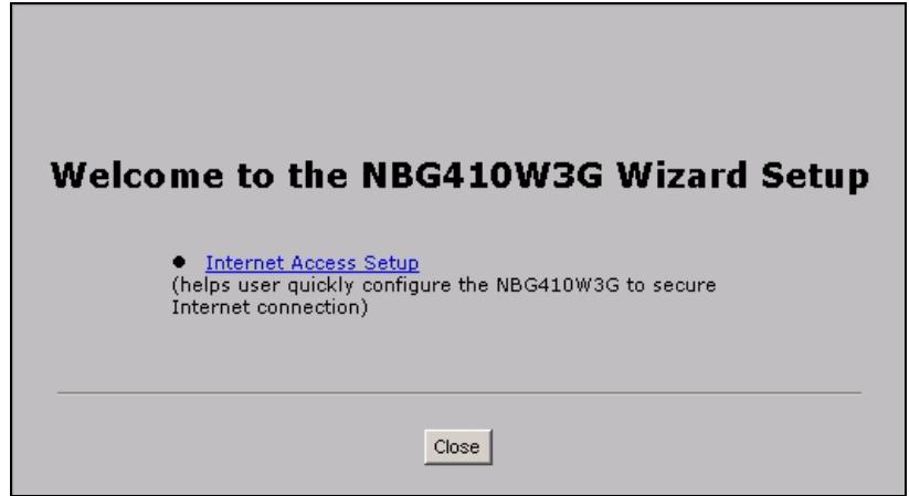
Figure 13 Wizard Setup Welcome
3.2 Internet Access
The Internet access wizard screen has three variations depending on what encapsulation type you use. Refer to information provided by your ISP to know what to enter in each field. Leave a field blank if you don't have that information.
3.2.1 ISP Parameters
The ZyXEL Device offers three choices of encapsulation. They are Ethernet, PPTP or PPPoE.
The wizard screen varies according to the type of encapsulation that you select in the Encapsulation field.
3.2.1.1 Ethernet
For ISPs (such as Telstra) that send UDP heartbeat packets to verify that the customer is still online, please create a WAN-to-WAN/ZyXEL Device firewall rule for those packets. Contact your ISP to find the correct port number.
Choose Ethernet when the WAN port is used as a regular Ethernet port.
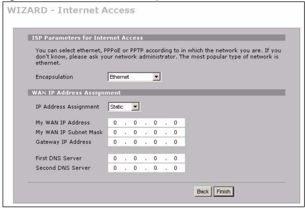
Figure 14 ISP Parameters: Ethernet Encapsulation
The following table describes the labels in this screen.
Table 9 ISP Parameters: Ethernet Encapsulation
| LABEL | DESCRIPTION |
| ISP Parameters for Internet Access | |
| Encapsulation | You must choose the Ethernet option when the WAN port is used as a regular Ethernet. Otherwise, choose PPPoE or PPTP for a dial-up connection. |
| WAN IP Address Assignment | |
| IP Address Assignment | Select Dynamic If your ISP did not assign you a fixed IP address. This is the default selection. Select Static If the ISP assigned a fixed IP address. The fields below are available only when you select Static. |
| My WAN IP Address | Enter your WAN IP address in this field. |
| My WAN IP Subnet Mask | Enter the IP subnet mask in this field. |
Table 9 ISP Parameters: Ethernet Encapsulation
| LABEL | DESCRIPTION |
| Gateway IP Address | Enter the gateway IP address in this field. |
| First DNS Server Second DNS Server | Enter the DNS server's IP address(es) in the field(s) to the right. Leave the field as 0.0.0.0 if you do not want to configure DNS servers. If you do not configure a DNS server, you must know the IP address of a machine in order to access it. |
| Back | Click Back to return to the previous wizard screen. |
| Finish | Click Finish to save your changes and go to the next screen. |
3.2.1.2 PPPoE Encapsulation
Point-to-Point Protocol over Ethernet (PPPoE) functions as a dial-up connection. PPPoE is an IETF (Internet Engineering Task Force) standard specifying how a host personal computer interacts with a broadband modem (for example DSL, cable, wireless, etc.) to achieve access to high-speed data networks.
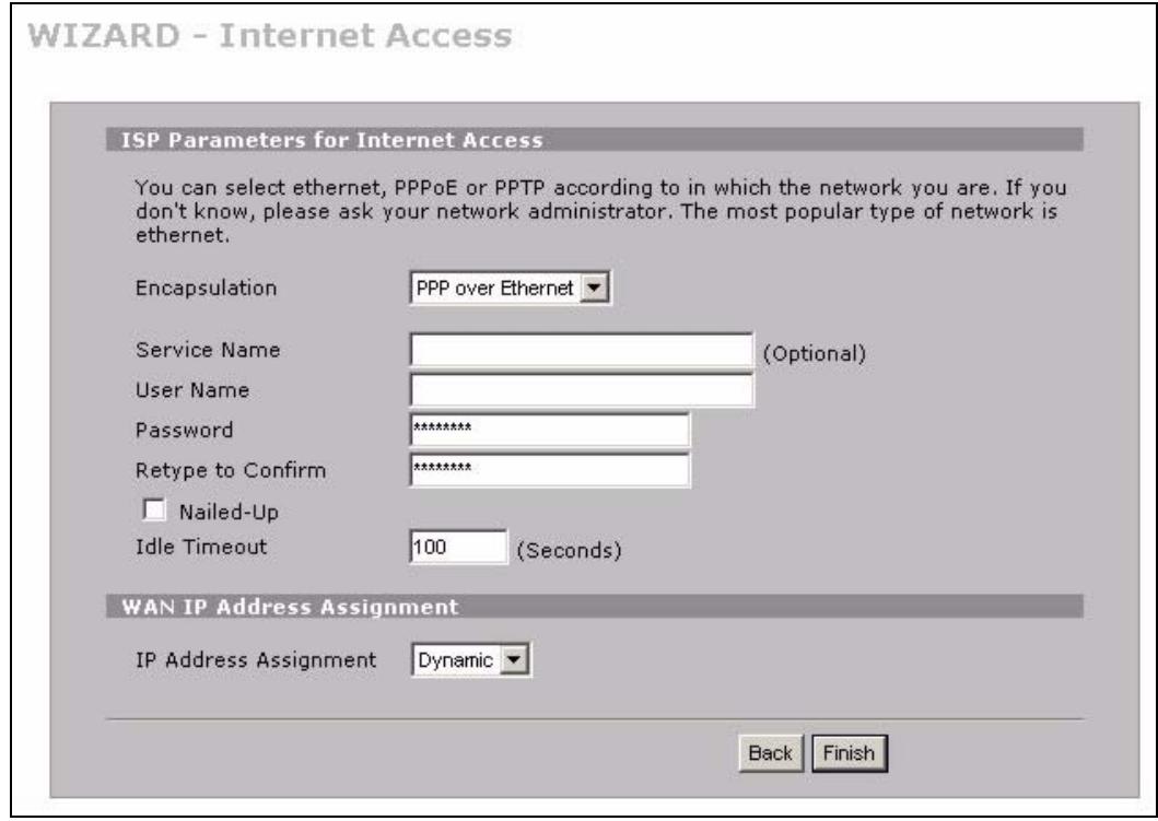
Figure 15 ISP Parameters: PPPoE Encapsulation
The following table describes the labels in this screen.
Table 10 ISP Parameters: PPPoE Encapsulation
| LABEL | DESCRIPTION |
| ISP Parameter for Internet Access | |
| Encapsulation | Choose an encapsulation method from the pull-down list box. PPP over Ethernet forms a dial-up connection. |
| Service Name | Type the name of your service provider. |
| User Name | Type the user name given to you by your ISP. |
| Password | Type the password associated with the user name above. |
| Rotypical to Confirm | Type your password again for confirmation. |
| Nailed-Up | Select Nailed-Up if you do not want the connection to time out. |
| Idle Timeout | Type the time in seconds that elapses before the router automatically disconnects from the PPPoE server. The default time is 100 seconds. |
| WAN IP Address Assignment | |
| IP Address Assignment | Select Dynamic If your ISP did not assign you a fixed IP address. This is the default selection. Select Static If the ISP assigned a fixed IP address. The fields below are available only when you select Static. |
| My WAN IP Address | Enter your WAN IP address in this field. |
| First DNS Server Second DNS Server | Enter the DNS server's IP address(es) in the field(s) to the right. Leave the field as 0.0.0.0 if you do not want to configure DNS servers. If you do not configure a DNS server, you must know the IP address of a machine in order to access it. |
| Back | Click Back to return to the previous wizard screen. |
| Finish | Click Finish to save your changes and go to the next screen. |
3.2.1.3 PPTP Encapsulation
Point-to-Point Tunneling Protocol (PPTP) is a network protocol that enables transfers of data from a remote client to a private server, creating a Virtual Private Network (VPN) using TCP/IP-based networks.
PPTP supports on-demand, multi-protocol, and virtual private networking over public networks, such as the Internet.

The ZyXEL Device supports one PPTP server connection at any given time.
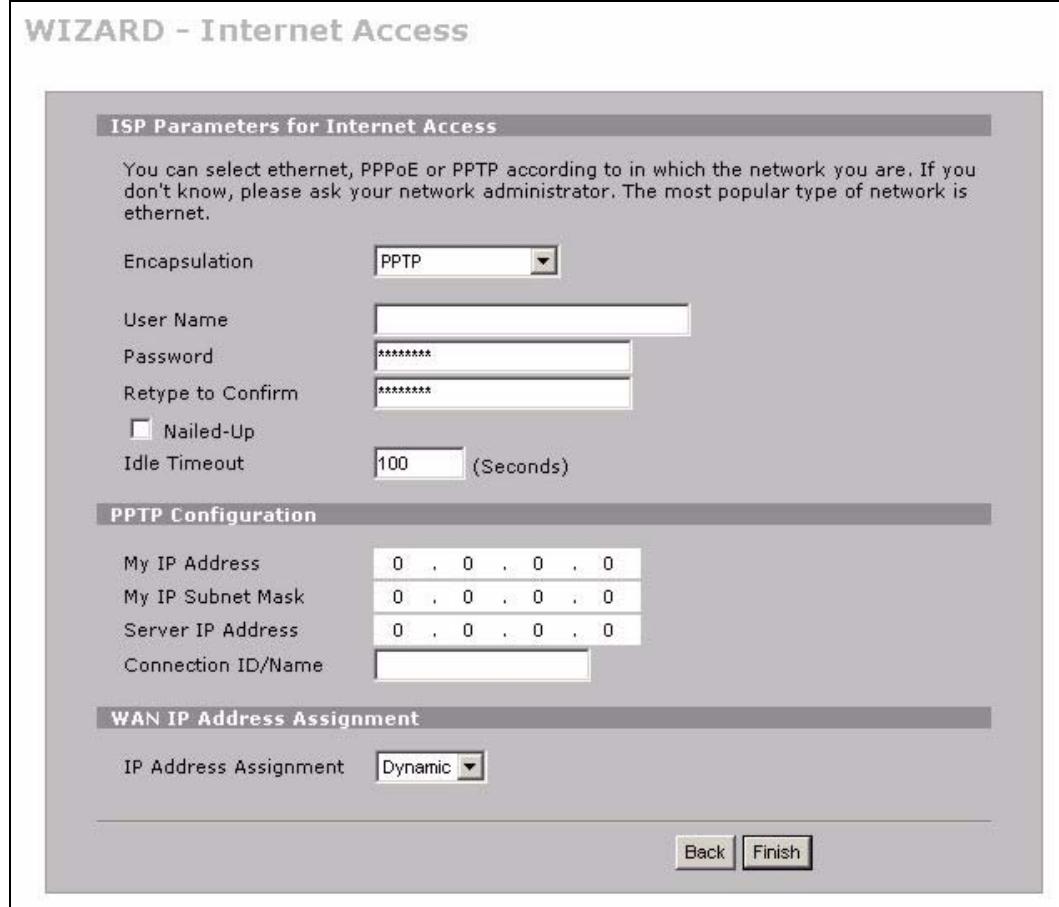
Figure 16 ISP Parameters: PPTP Encapsulation
The following table describes the labels in this screen.
Table 11 ISP Parameters: PPTP Encapsulation
| LABEL | DESCRIPTION |
| ISP Parameters for Internet Access | |
| Encapsulation | Select PPTP from the drop-down list box. To configure a PPTP client, you must configure the User Name and Password fields for a PPP connection and the PPTP parameters for a PPTP connection. |
| User Name | Type the user name given to you by your ISP. |
| Password | Type the password associated with the User Name above. |
| Retype to Confirm | Type your password again for confirmation. |
| Nailed-Up | Select Nailed-Up if you do not want the connection to time out. |
| Idle Timeout | Type the time in seconds that elapses before the router automatically disconnects from the PPTP server. |
| PPTP Configuration | |
| My IP Address | Type the (static) IP address assigned to you by your ISP. |
| My IP Subnet Mask | Type the subnet mask assigned to you by your ISP (if given). |
| Server IP Address | Type the IP address of the PPTP server. |
Table 11 ISP Parameters: PPTP Encapsulation
| LABEL | DESCRIPTION |
| Connection ID/ Name | Enter the connection ID or connection name in this field. It must follow the "c:id" and "n:name" format. For example, C:12 or N:My ISP. This field is optional and depends on the requirements of your xDSL modem. |
| WAN IP Address Assignment | |
| IP Address Assignment | Select Dynamic If your ISP did not assign you a fixed IP address. This is the default selection. Select Static If the ISP assigned a fixed IP address. The fields below are available only when you select Static. |
| My WAN IP Address | Enter your WAN IP address in this field. |
| First DNS Server Second DNS Server | Enter the DNS server's IP address(es) in the field(s) to the right. Leave the field as 0.0.0.0 if you do not want to configure DNS servers. If you do not configure a DNS server, you must know the IP address of a machine in order to access it. |
| Back | Click Back to return to the previous wizard screen. |
| Finish | Click Finish to save your changes and go to the next screen. |
3.2.2 Internet Access Wizard Setup Complete
The congratulations screen displays. Click Close to complete the Internet access setup.
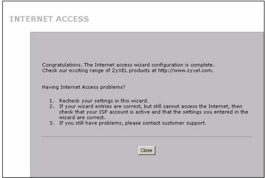
Figure 17 Internet Access Setup Complete
Tutorials
This section describes how to do the following.
1 Set up a DMZ (De-Militarized Zone).
2 Use an H.323 VoIP phone on your LAN.
3 Use NAT (Network Address Translation) with multiple public IP addresses.
4 Allow multiple game players to connect to the same server.
4.1 DMZ Overview
The DMZ is a separate network for devices that provide services to users on the Internet. Devices such as a web or e-mail server are more prone to security threats as they are more visible from the Internet and more frequently accessed than devices on your LAN. By placing such devices on a DMZ, you can better restrict access to the devices on your LAN.
The diagram shows servers on the DMZ which are open to public access but protected by the ZyXEL Device's firewall. Devices which require greater security are located on the LAN.
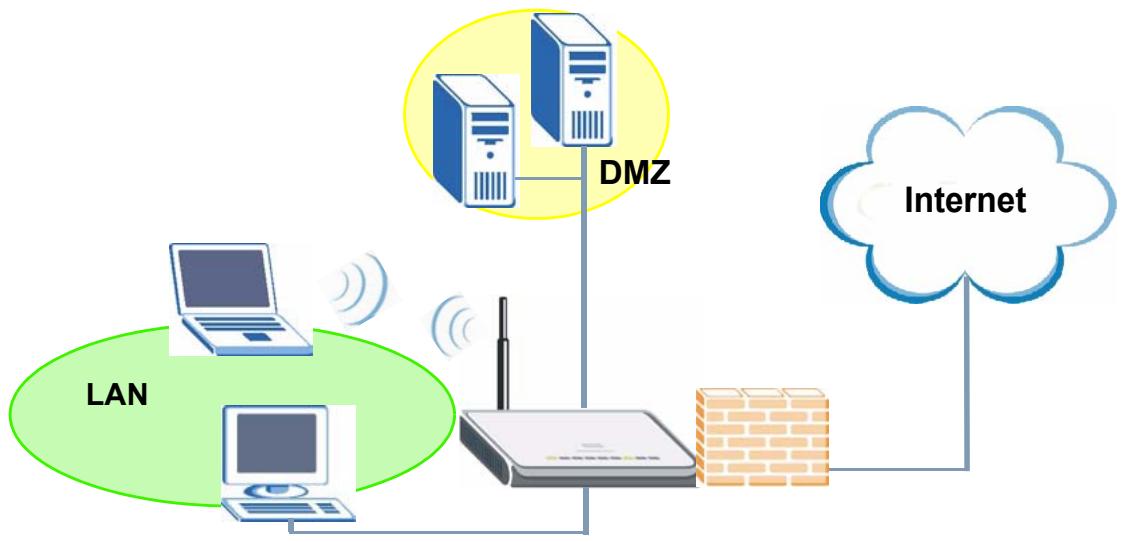
Figure 18 DMZ Overview
In this situation a file server is located in the DMZ. The file server is available for public access from the Internet and also from computers located on the LAN.
You can use either public or private IP addresses for your DMZ, however the DMZ must be on a different subnet or network from the LAN.
4.2 DMZ Setup Example
In this example the DMZ uses private IP addresses and the default subnet mask of 255.255.255.0. (See Appendix C on page 377 for information on subnetting.) You can also use a static public IP address for your file server.
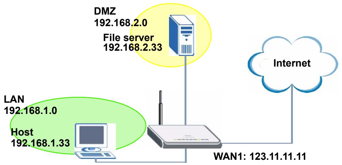
Figure 19 DMZ Tutorial: DMZ Setup
4.2.1 Basic Setup
Follow these steps to set up your DMZ with a private or a public IP address.
4.2.1.1 Private IP Address
1 Click NETWORK > DMZ to open the DMZ screen. In the DMZ TCP/IP field type your DMZ IP address in the IP address field. In the IP Subnet Mask field type the same subnet mask as that used on the LAN.
2 Select Server from the drop-down list in the DHCP field to have the ZyXEL Device dynamically assign IP addresses to devices on the DMZ. In the IP Pool Starting Address field type the first available IP address for the DMZ subnetwork. In this example 192.168.2.33 is used. Skip to Section 4.2.1.3 on page 67.
4.2.1.2 Public IP Address
Either configure a static IP address on the server directly using the server's operating system, or follow these steps to set up static DHCP on the ZyXEL Device.
1 Click NETWORK > DMZ > Static DHCP to open the Static DHCP screen.
2 Type the MAC address of the file server in the MAC Address field and a valid IP address on your DMZ in the IP Address field. In this example the MAC address is 00:A0:C5:00:00:02 and the IP address is 192.168.2.33.
3 Click Apply. That completes setup of static DHCP on the ZyXEL Device.
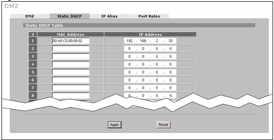
Figure 20 DMZ Tutorial: NETWORK > DMZ > Static DHCP
4.2.1.3 Public and Private IP Addresses
1 In Windows Networking (NetBIOS over TCP/IP) select Allow between DMZ and LAN. In this example, both the file server on the DMZ and a computer on the LAN use a Windows OS. Enable NetBIOS to allow LAN computers to use Windows programs such as Windows Explorer to access the server on the DMZ.
2 Click Apply.
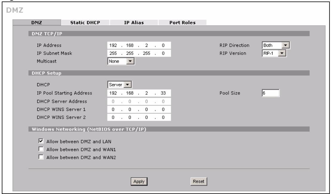
Figure 21 DMZ Tutorial: NETWORK > DMZ
3 Ensure NAT (Network Address Translation) is enabled on your WAN to allow the ZyXEL Device to manage the IP addresses of traffic it routes between networks. Click ADVANCED > NAT. For your WAN connection select. In this example NAT is enabled in the Enable NAT field on WAN1 and SUA is selected. For more information on this screen see Chapter 12 on page 225.
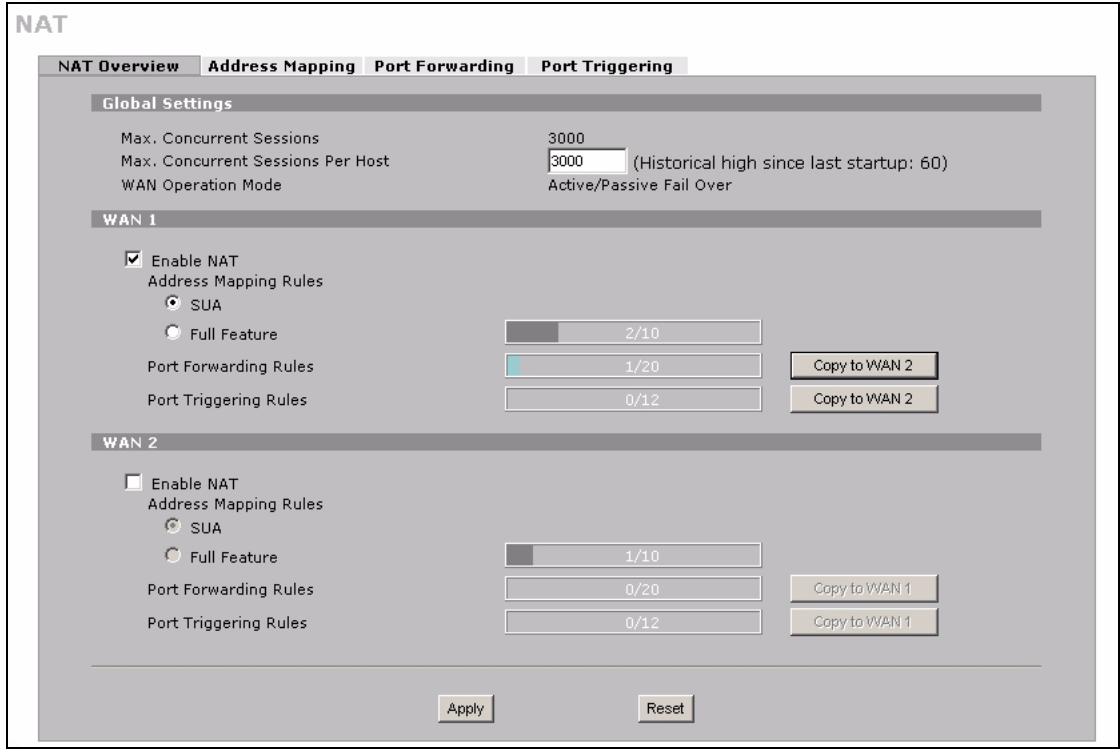
Figure 22 DMZ Tutorial: ADVANCED > NAT Overview
This completes basic setup of your DMZ.
4.2.2 Advanced Setup
In this scenario the file server runs an FTP (File Transfer Protocol) download service. Since FTP is not compatible with NAT, you can use the ALG (Application Layer Gateway) to manage FTP. (See Chapter 18 on page 293 for more information.)
To allow FTP sessions to be initiated by users on the WAN, port-forwarding is also required (see Section 12.5 on page 235 for more information) and for port-forwarding the file server needs a static IP address.
ALG Setup
To turn on the ZyXEL Device's FTP ALG, click ADVANCED > ALG. Select Enable FTP ALG and click Apply.
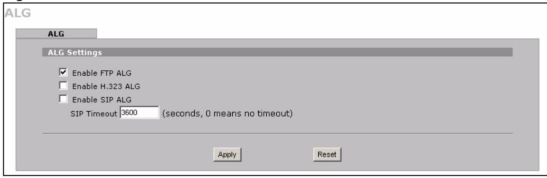
Figure 23 DMZ Tutorial: ADVANCED > ALG
Port Forwarding Setup
1 To configure port forwarding, first configure a static IP on the file server if you haven't already. See Section 4.2.1.2 on page 66.
2 Click ADVANCED > NAT > Port Forwarding to open the Port Forwarding screen.
3 In the WAN Interface field select the correct WAN for your network. This example uses WAN1.
4 In the rule row you are configuring select Active.
5 In the Name field type a descriptive name for the port forwarding rule. This example uses FTP.
6 In the Incoming Port(s) field type the port number used by the FTP application. This example uses 69.
7 In the Server IP Address field type the IP address of your file server. This example uses 192.168.1.33.
8 Click Apply.
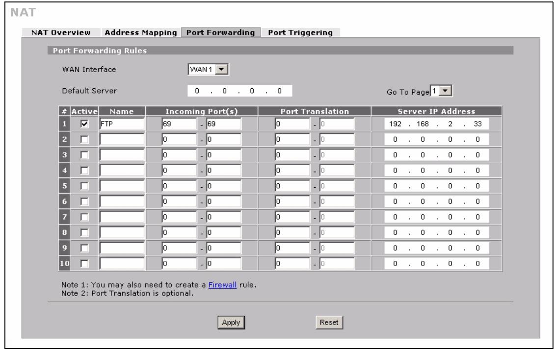
Figure 24 DMZ Tutorial: ADVANCED > NAT > Port Forwarding
This completes setup of NAT-incompatible services on the server in your DMZ. Now users can access the file server on your DMZ from the Internet.
4.3 Firewall Rule Setup
Your ZyXEL Device's firewall default settings provide network security by allowing traffic from the WAN to your DMZ, and blocking traffic from the DMZ to the LAN. However, you can further enhance network security by defining firewall rules specifically for traffic from the WAN to the DMZ.
You need to define two rules - one to drop all traffic from the WAN to the DMZ, the other to permit HTTP and FTP traffic from the WAN to the DMZ. This ensures that only HTTP and FTP traffic from the WAN to the DMZ is permitted and all other traffic is blocked.
If you have not already done so, define a static IP address for the file server (see step 1 on page 69 for instructions).
1 Click SECURITY > Firewall > Rule Summary to display the Rule Summary screen. Use this screen to configure firewall rules on traffic between the file server and the WAN. In this example, traffic from WAN1 to the file server is restricted to HTTP and FTP traffic.
2 The Rule Summary screen appears. Select WAN1 and DMZ from the drop-down list in the Packet Direction field and click Refresh. Click the Modify ( ) icon to add a new rule.
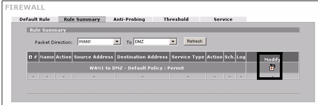
Figure 25 DMZ Tutorial: SECURITY > Firewall > Rule Summary
3 The Firewall - Edit screen appears. Type the name of the firewall rule in the Rule Name field. In this example WAN12DMZ - DENY is used.
4 In the Edit Source Address section select Any Address in the drop-down box in the Address Type field to define the source address of traffic from the Internet as any IP address.
5 In the Edit Destination Address section select Single Address in the drop-down box in the Address Type field. Type the destination address of traffic in the Start IP Address field. In this case the WAN1 IP address is used - 123.23.23.23. If you are using a public static IP address for your web server, type the server's IP address in this field.
6 Click Add so that the IP address appears in the Destination Address(es) field.
7 In the Edit Service section of the Firewall - Edit screen select Any so that they appear in the Selected Service(s) field.
8 In the Action for Matched Packets field select Drop from the drop-down box.
9 In the Edit Service section select FTP and click the arrow icon. Then select HTTP and click the arrow icon again so that FTP and HTTP appear in the Selected Service(s) field.
10 Click Apply.
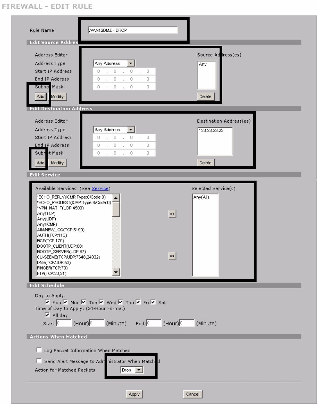
Figure 26 DMZ Tutorial: NETWORK > Firewall > Rule Summary: Firewall - Edit
11 Repeat the firewall rule setup procedure to set up a rule for WAN1 to DMZ traffic with the same source and destination addresses. In the Edit Service section of the Firewall - Edit screen select HTTP and FTP so that they appear in the Selected Service(s) field.
12 In the Action for Matched Packets field select Permit from the drop-down list and click Apply.
13 In the Rule Summary screen select Any and Any from the drop-down list in the Packet Direction fields and click Refresh to check your firewall rule settings.
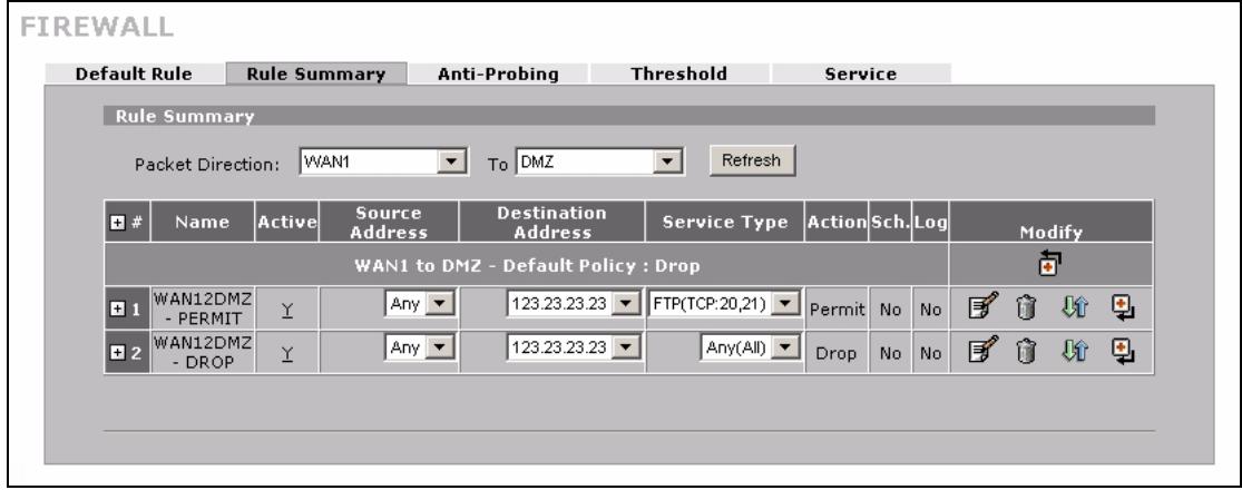
Figure 27 DMZ Tutorial: SECURITY > Firewall > Rule Summary Example
This completes setup of a firewall rules for the file server on your DMZ.
4.4 Setting Up a VoIP Phone with H.323
You can use the ZyXEL Device to manage calls from your VoIP enabled phone using H.323. The following diagram shows an example of a VoIP phone configured to make calls over the Internet.
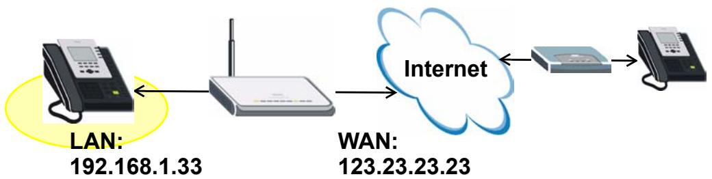
Figure 28 Tutorial: H.323 Phone Setup
To configure your ZyXEL Device to allow VoIP phone calls using your H.323 phone, you need to set up the H.323 ALG (Application Layer Gateway) and port forwarding, which in turn requires a fixed IP address for your phone.
IP Address Settings
Follow these steps to give your phone a fixed IP address.
1 Click NETWORK > LAN > Static DHCP to open the Static DHCP screen.
2 Type the MAC address of your device in the MAC Address field and a valid IP address on your LAN in the IP Address field. In this example the MAC address is 00:A0:C5:00:00:02 and the IP address is 192.168.1.33.
3 Click Apply.
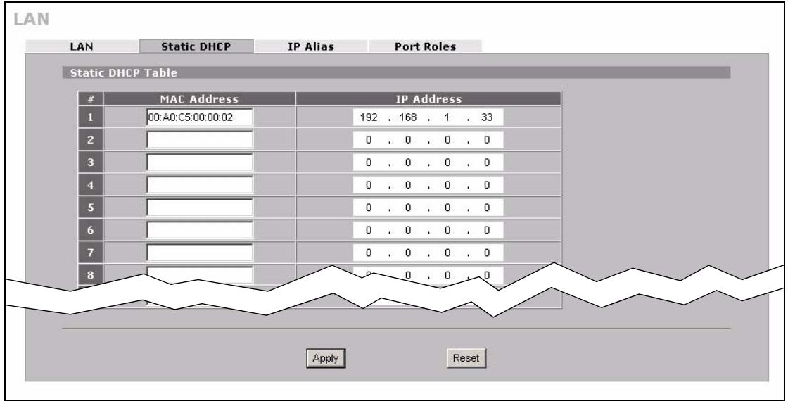
Figure 29 H.323 Tutorial: NETWORK > LAN > Static DHCP
4 Click NETWORK > LAN to display the LAN screen. Ensure that Server is selected in the drop-down box in the DHCP field.
Setup ALG
Follow these steps to set up ALG (Application Layer Gateway) to let your ZyXEL Device manage H.323 traffic. (For more information on ALG see Chapter 18 on page 293.)
1 Click ADVANCED > ALG to display the ALG screen. Select Enable H.323 ALG and click Apply. This configures ALG (Application Layer Gateway) to manage H.323 traffic through your ZyXEL Device.
2 Click Apply.
ALG
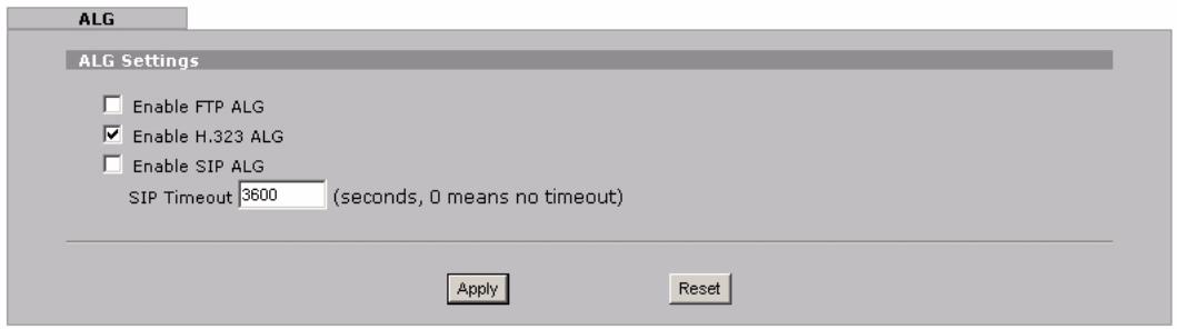
Figure 30 H.323 Tutorial: ADVANCED > ALG
Set up Port Forwarding
1 Click ADVANCED > NAT > Port Forwarding to display the Port Forwarding screen.
2 Select the correct WAN for your network in the WAN Interface field.
3 Select Active in the rule row you are configuring.
4 Type a descriptive name for the port forwarding rule in the Name field. In this example H.323 is used.
5 Type 1720 in the Incoming Port(s) field. This port number is used for the H.323 services.
6 Type the IP address of your VoIP phone in the Server IP Address field. In this example 192.168.1.33 is used.
7 Click Apply.
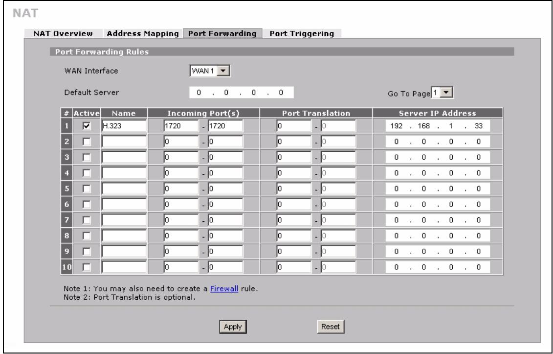
Figure 31 H.323 Tutorial: ADVANCED > NAT > Port Forwarding
Setup a Firewall Rule
1 Click SECURITY > Firewall > Rule Summary to display the Rule Summary screen and to configure firewall rules on traffic between the VoIP phone and the WAN. In this example, traffic between the file server and WAN1 is restricted to H.323 traffic.
2 The Rule Summary screen appears. Select DMZ and WAN1 from the drop-down list in the Packet Direction field and click Refresh. Click the Modify (向) icon to add a new rule.
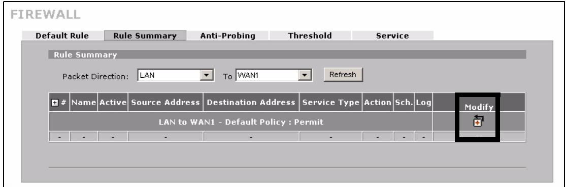
Figure 32 H.323 Tutorial: SECURITY > Firewall > Rule Summary
3 The Firewall - Edit screen appears. Type the name of the firewall rule in the Rule Name field. In this example LAN2WAN1 - H.323 is used.
4 In the Edit Source Address section select Single Address in the drop-down box in the Address Type field. Type the source address of H.323 traffic in the Start IP Address
field - 123.23.23.23 and click Add so that the IP address appears in the Destination Address(es) field. If you are using a H.323 server, use its IP address instead.
5 In the Edit Destination Address section select Single Address in the drop-down box in the Address Type field. Type the destination address of H.323 traffic in the Start IP Address field - 192.168.1.33 and click Add so that the IP address appears in the Source Address(es) field.
6 In the Edit Service section select H.323 and click the arrow icon so that H.323 appears in the Selected Service(s) field.
7 Click Apply.
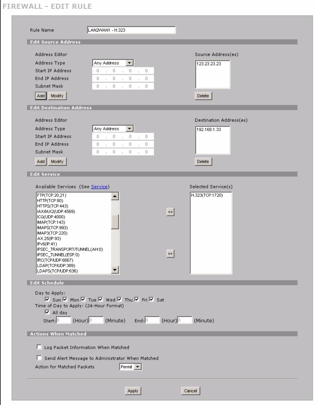
Figure 33 H.323 Tutorial: SECURITY > Firewall > Rule Summary
8 Repeat the firewall rule setup procedure to add a similar firewall rule for H.323 traffic from the WAN to the LAN, using the same WAN IP address and LAN IP address settings.
9 In the Rule Summary screen select Any and Any from the drop-down list in the Packet Direction fields and click Refresh to check your firewall rule settings.
Figure 34 H.323 Tutorial: SECURITY > Firewall > Rule Summary
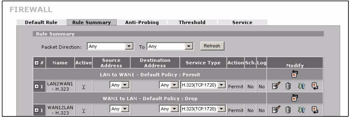
That completes setup of your H.323 VoIP phone.
4.5 Using NAT with Multiple Public IP Addresses
This section shows you examples of how to set up your ZyXEL Device if you have more than one fixed (static) IP address from your ISP.
4.5.1 Example Parameters and Scenario
The following table shows the public IP addresses from your ISP and your ZyXEL Device's LAN IP address.
| Public IP Addresses | 1.2.3.4 to 1.2.3.7 |
| ZyXEL Device's LAN IP Address | 192.168.1.1 |
The following figure shows the network you want to set up in this example.
- Assign the first public address (1.2.3.4) to the ZyXEL Device's WAN 1 port.
- Map the second and third public IP addresses (1.2.3.5 and 1.2.3.6) to the web and mail servers (192.168.1.12 and 192.168.1.13) respectively for traffic in both directions.
- Map the first public address (1.2.3.4) to outgoing traffic from other local computers.
Map the first public address (1.2.3.4) to incoming traffic from WAN 1. - Forward FTP traffic using port 21 from WAN 1 to a specific local computer (192.168.1.39).
- The last public IP address (1.2.3.7) is not mapped to any device and is reserved for future use.
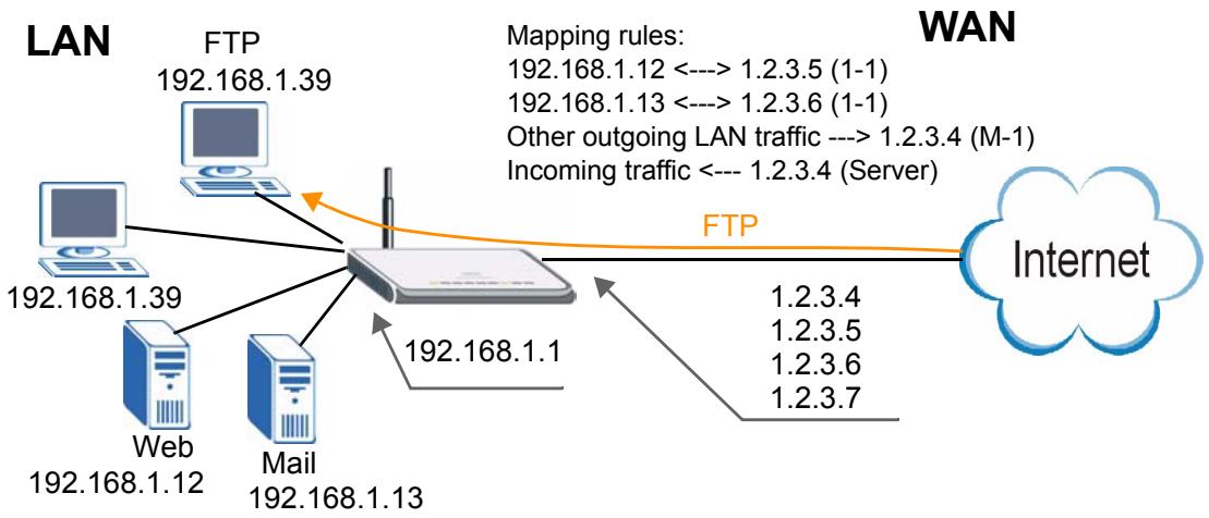
Figure 35 Tutorial Example: Using NAT with Static Public IP Addresses
To set up this network, we are going to:
1 Configure the WAN 1 connection to use the first public IP address (1.2.3.4).
2 Configure NAT address mapping for other public IP addresses (1.2.3.5 and 1.2.3.6).
3 Configure NAT port forwarding to forward FTP traffic from WAN 1 to a specific computer on your local network.
4.5.2 Configuring the WAN Connection with a Static IP Address
The following table shows the information your ISP gave you for Internet connection.
| Encapsulation | PPPoE |
| Public IP Addresses | 1.2.3.4 |
| 1.2.3.5 | |
| 1.2.3.6 | |
| 1.2.3.7 | |
| Gateway IP Address | 1.2.3.89 |
| Subnet Mask | 255.255.255.0 |
| User Name | exampleuser |
| Password | abcd1234 |
| DNS Server | 1.2.1.1 |
| 1.2.1.2 |
Follow the steps below to configure your ZyXEL Device for Internet access using PPPoE in this example.
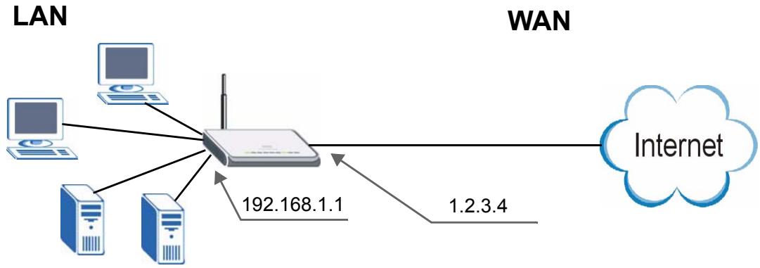
Figure 36 Tutorial Example: WAN Connection with a Static Public IP Address
1 Click NETWORK > WAN > WAN 1.
2 Select PPPoE (PPP over Ethernet) from the Encapsulation drop-down list box.
3 In the ISP Parameters for Internet Access section, enter the information (such as the user name and password) provided by your ISP. If your ISP didn't give you the service name, leave the field blank.
4 In the WAN IP Address Assignment section, select Use Fixed IP Address and enter the first fixed public IP address (1.2.3.4 in this example).
5 Click Apply.
Figure 37 Tutorial Example: WAN 1 Screen
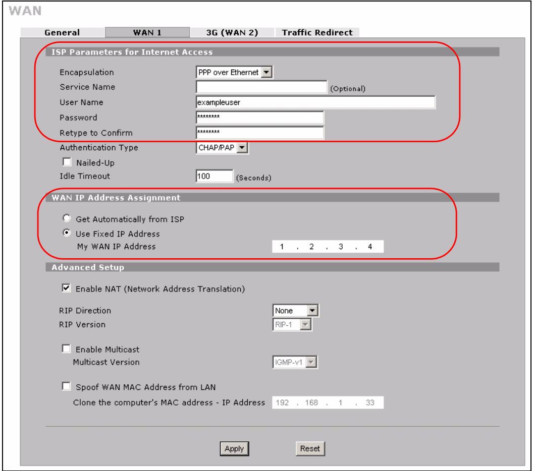
6 Click ADVANCED > DNS.
7 The System screen displays. Click the Insert button to configure the IP address of the DNS server the ZyXEL Device can query to resolve domain names.
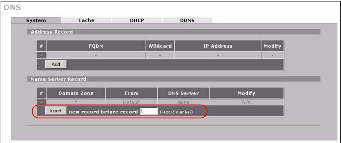
Figure 38 Tutorial Example: DNS > System
8 Select Public DNS Server and enter the first DNS server's IP address given by your ISP. Click Apply.

Figure 39 Tutorial Example: DNS > System Edit-1
9 Enter the rule number (2) where you want to put the second record and click the Insert button to configure the second DNS server's IP address as follows. Click Apply.

To resolve a domain name, theZyXEL Device checks it against the name server record entries in the order that they appear in this list.
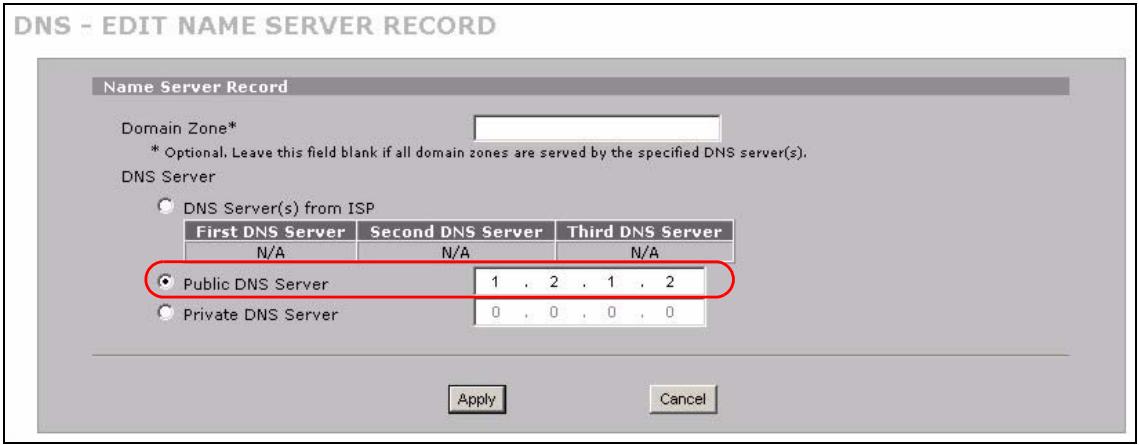
Figure 40 Tutorial Example: DNS > System Edit-2
10 The DNS > System screen should look as shown.
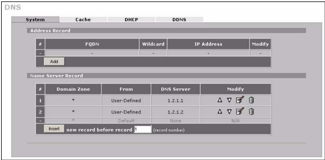
Figure 41 Tutorial Example: DNS > System: Done
11 Go to the Home screen to check your WAN connection status. Make sure the status is not down.
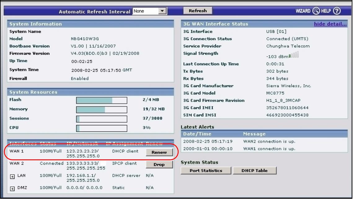
Figure 42 Tutorial Example: Status
4.5.3 Public IP Address Mapping
To have the local computers and servers use specific WAN IP addresses, you need to map static public IP addresses to them.

The one-to-one NAT address mapping rules are for both incoming and outgoing connections. The ZyXEL Device forwards traffic that is initiated from either the LAN or the WAN to the destination IP address.

The many-to-one or many-to-many NAT address mapping rules are for outgoing connections only. That means only traffic initiated from the LAN or returned packets are allowed to go through the ZyXEL Device.
In this example, you create two one-to-one rules to map the internal web server (192.168.1.12) and mail server (192.168.1.13) to different static public IP addresses. The many-to-one rule maps a public IP address (1.2.3.4, that is, the ZyXEL Device's WAN 1 IP address) to outgoing LAN traffic. It allows other local computers on the same subnet as the ZyXEL Device's LAN IP address to use this IP address to access the Internet.
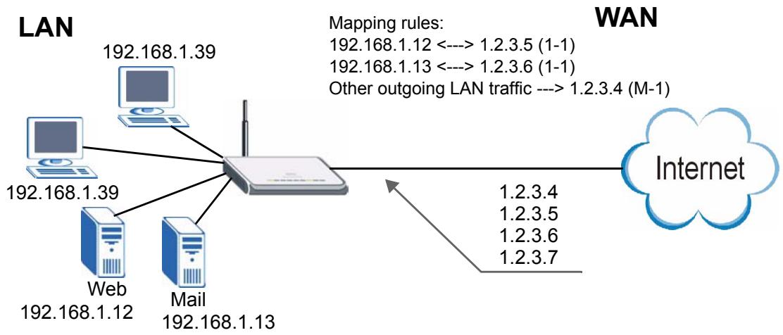
Figure 43 Tutorial Example: Mapping Multiple Public IP Addresses to Inside Servers

The ZyXEL Device applies the rules in the order that you specify. You should put any one-to-one rules before a many-to-one rule.
1 Click ADVANCED > NAT.
2 Enable NAT and select Full Feature for the WAN 1 interface as you have multiple public IP addresses to map to private IP addresses. Click Apply.
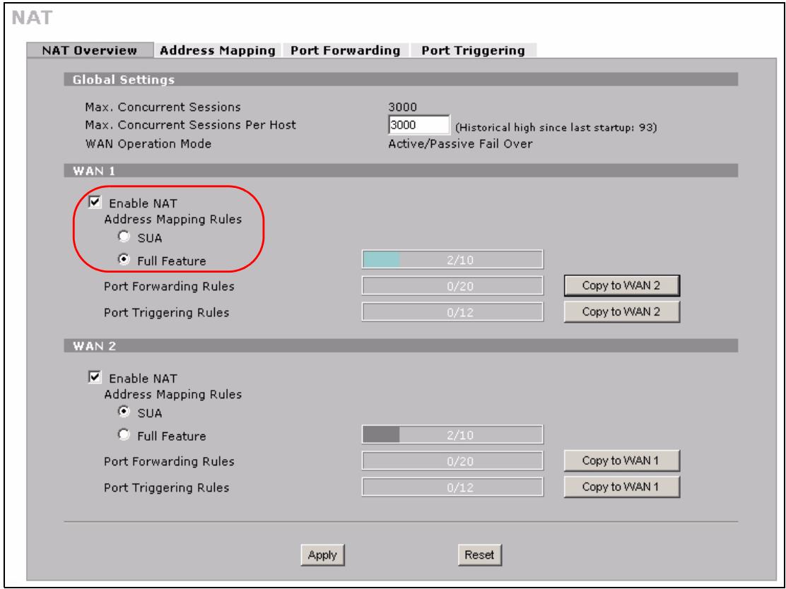
Figure 44 Tutorial Example: NAT > NAT Overview
3 Click the Address Mapping tab.
4 Select WAN 1.
5 Click the first rule's Edit icon (E) in the Modify column to display the Address Mapping Rule screen.
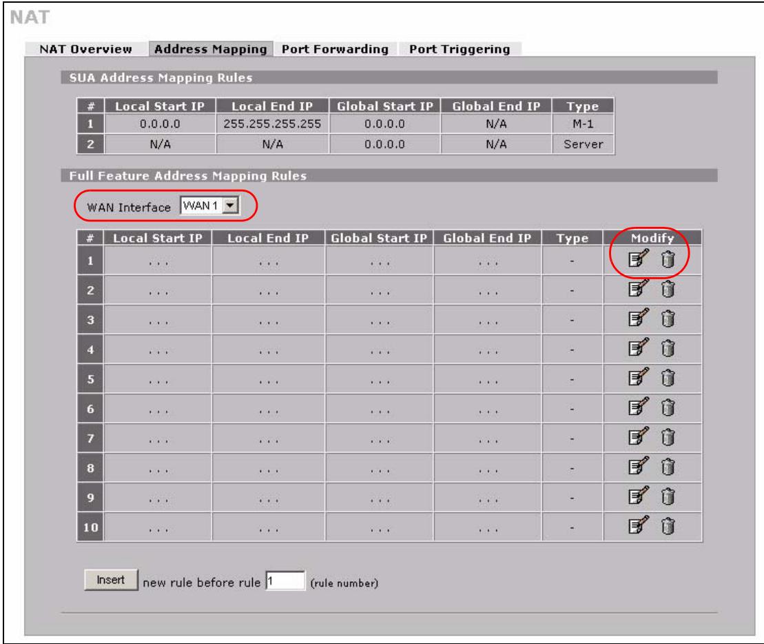
Figure 45 Tutorial Example: NAT > Address Mapping
6 Map a public IP address to the web server.
Select the One-to-One type and enter 192.168.1.12 as the local start IP address and 1.2.3.5 as the global start IP address. Click Apply.
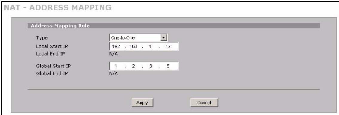
Figure 46 Tutorial Example: NAT Address Mapping Edit: One-to-One (1)
7 Click the second rule's Edit icon (B).
8 Map a public IP address to the mail server. Select the One-to-One type and enter 192.168.1.13 as the local start IP address and 1.2.3.6 as the global start IP address. Click Apply.
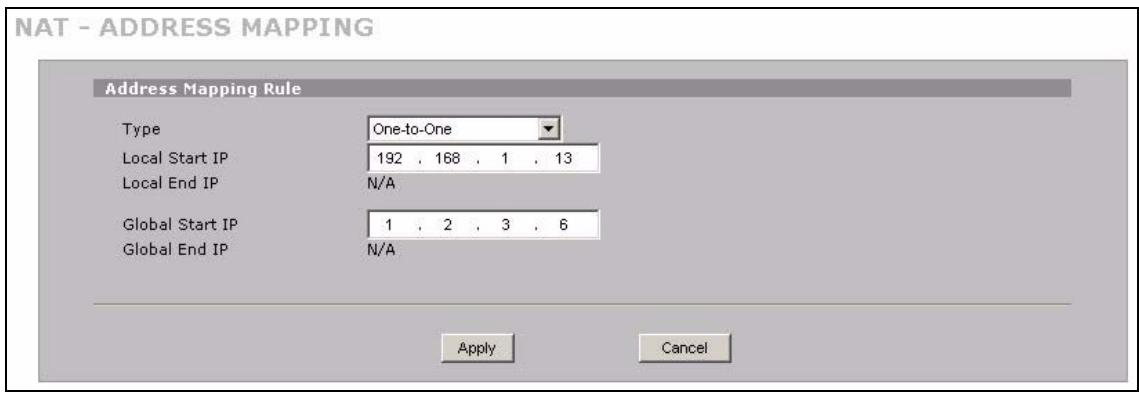
Figure 47 Tutorial Example: NAT Address Mapping Edit: One-to-One (2)
9 Click the third rule's Edit icon (E).
10 Map a public IP address to other outgoing LAN traffic.
Select the Many-to-One type and enter 192.168.1.1 as the local start IP address, 192.168.1.254 as the local end IP address and 1.2.3.4 as the global start IP address. Click Apply.
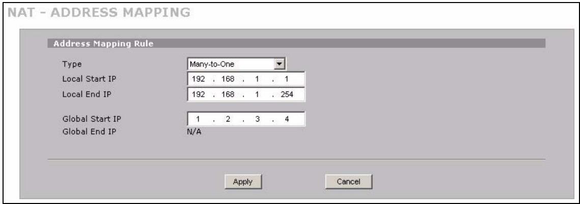
Figure 48 Tutorial Example: NAT Address Mapping Edit: Many-to-One
11 After the configurations, the Address Mapping screen looks as shown. You still have one IP address (1.2.3.7) that can be assigned to another internal server when you expand your network.
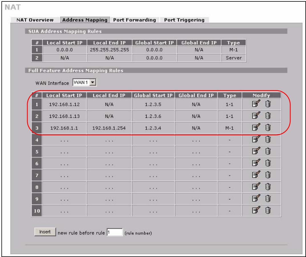
Figure 49 Tutorial Example: NAT Address Mapping Done

To allow traffic from the WAN to be forwarded through the ZyXEL Device, you must also create a firewall rule. Refer to Section 4.5.5 on page 89 for more information.
4.5.4 Forwarding Traffic from the WAN to a Local Computer
A server NAT address mapping rule allows computers behind the NAT be accessible to the outside world. To have the ZyXEL Device forward incoming traffic to a specific computer on your local network, you should also create a port forwarding (server mapping) rule.
In this example, you want to forward FTP traffic using port 21 to the computer with the IP address of 192.168.1.39.
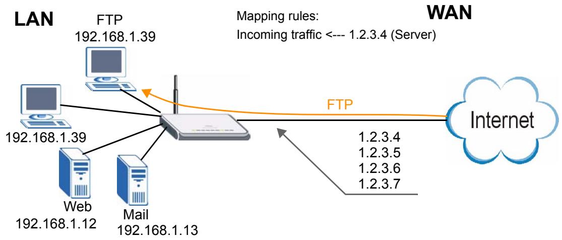
Figure 50 Tutorial Example: Forwarding Incoming FTP Traffic to a Local Computer
1 Click ADVANCED > NAT > Address Mapping.
2 Click the forth rule's Edit icon (E) to configure a server rule.
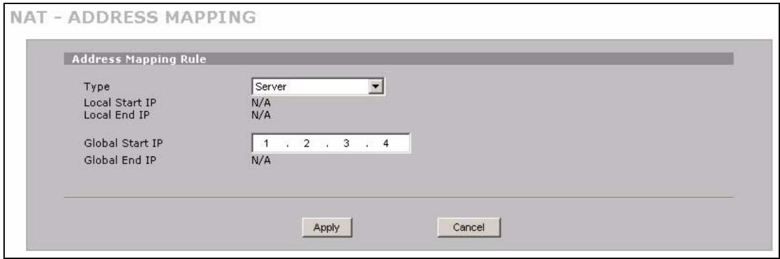
Figure 51 Tutorial Example: NAT Address Mapping Edit: Server
3 Click the Port Forwarding tab.
4 Select WAN 1.
5 Select the Active check box, enter a descriptive name (FTP for example), incoming port number (21) and 192.168.1.39 as the server IP address. Click Apply.
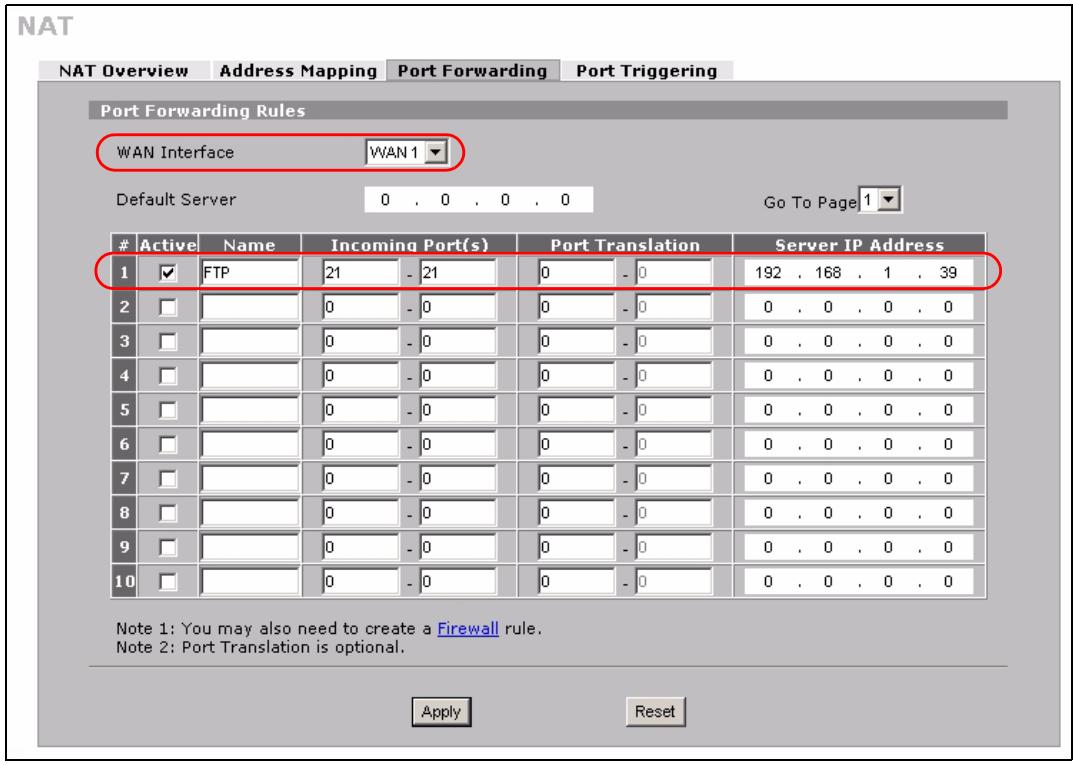
Figure 52 Tutorial Example: NAT Port Forwarding
4.5.5 Allow WAN-to-LAN Traffic through the Firewall
By default, the ZyXEL Device blocks any traffic initiated from the WAN to the LAN. To have the ZyXEL Device forward traffic initiated from WAN 1 to a local computer or server on the LAN, you need to configure a firewall rule to allow it.
In this example, you create the firewall rules to allow traffic from the WAN to the following servers on the LAN:
Web server
- Mail server
FTP server
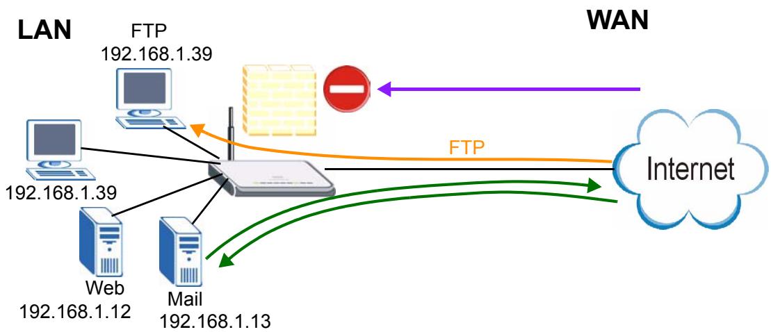
Figure 53 Tutorial Example: Forwarding Incoming FTP Traffic to a Local Computer
1 Click SECURITY > FIREWALL.
2 Make sure the firewall is enabled and traffic from WAN 1 to the LAN is dropped.
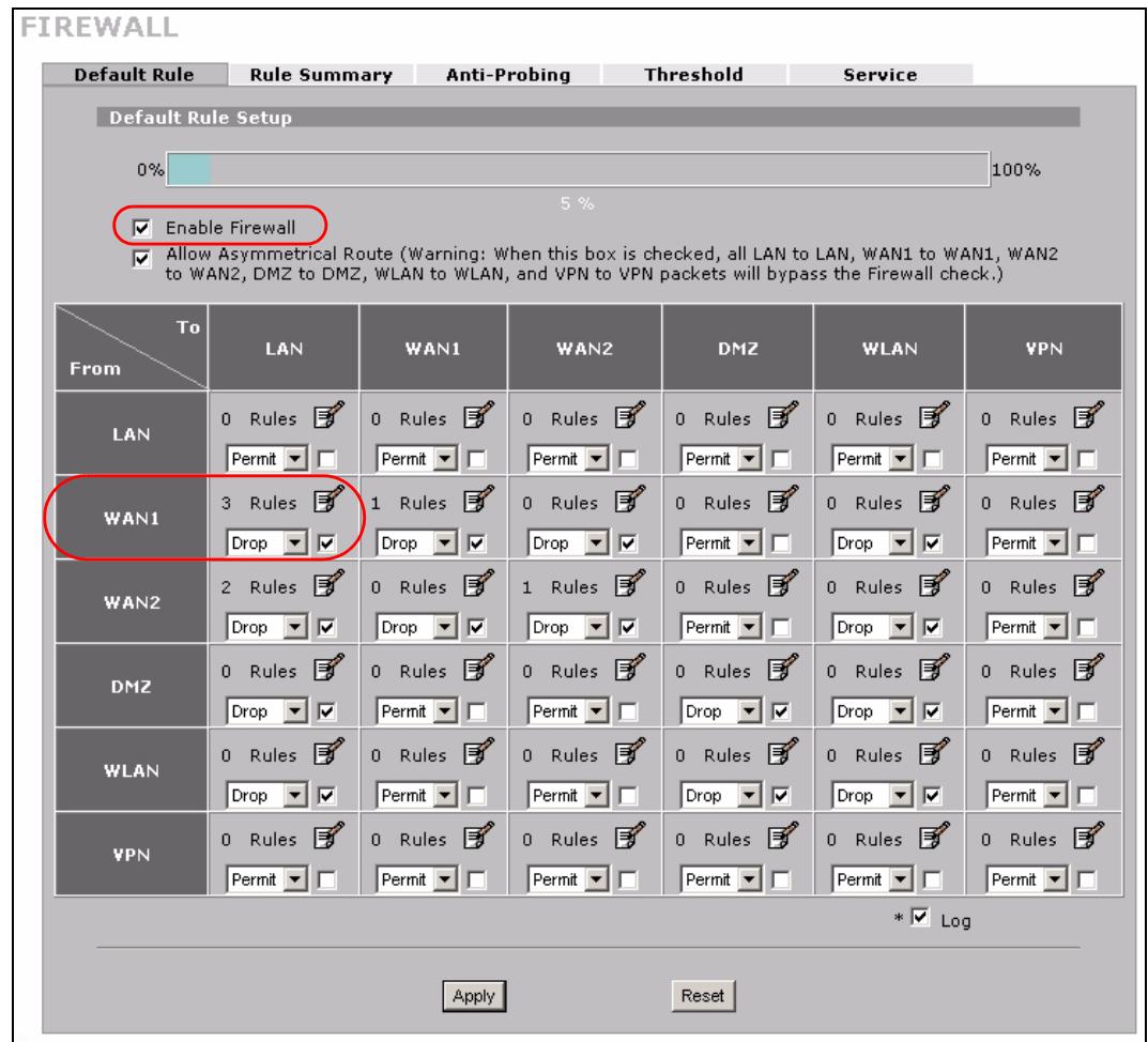
Figure 54 Tutorial Example: Firewall Default Rule
3 Go to the Rule Summary screen.
4 Select WAN1 to LAN as the packet direction and click Refresh.
5 Click the insert icon to create a new firewall rule.
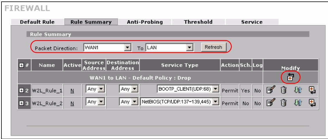
Figure 55 Tutorial Example: Firewall Rule: WAN1 to LAN
6 Configure a firewall rule to allow HTTP traffic from the WAN to the web server.
Enter a descriptive name (W-L_Web for example).
Select Any in the Destination Address(es) box and click Delete.
Select Single Address as the destination address type. Enter 192.168.1.12 and click Add.
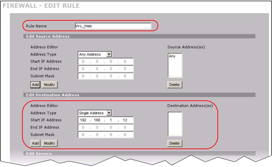
Figure 56 Tutorial Example: Firewall Rule: WAN to LAN Address Edit for Web Server
7 Select HTTP(TCP:80) and HTTPS(TCP:443) in the Available Services box on the left, and click >> to add them to the Selected Service(s) box on the right. Click Apply.
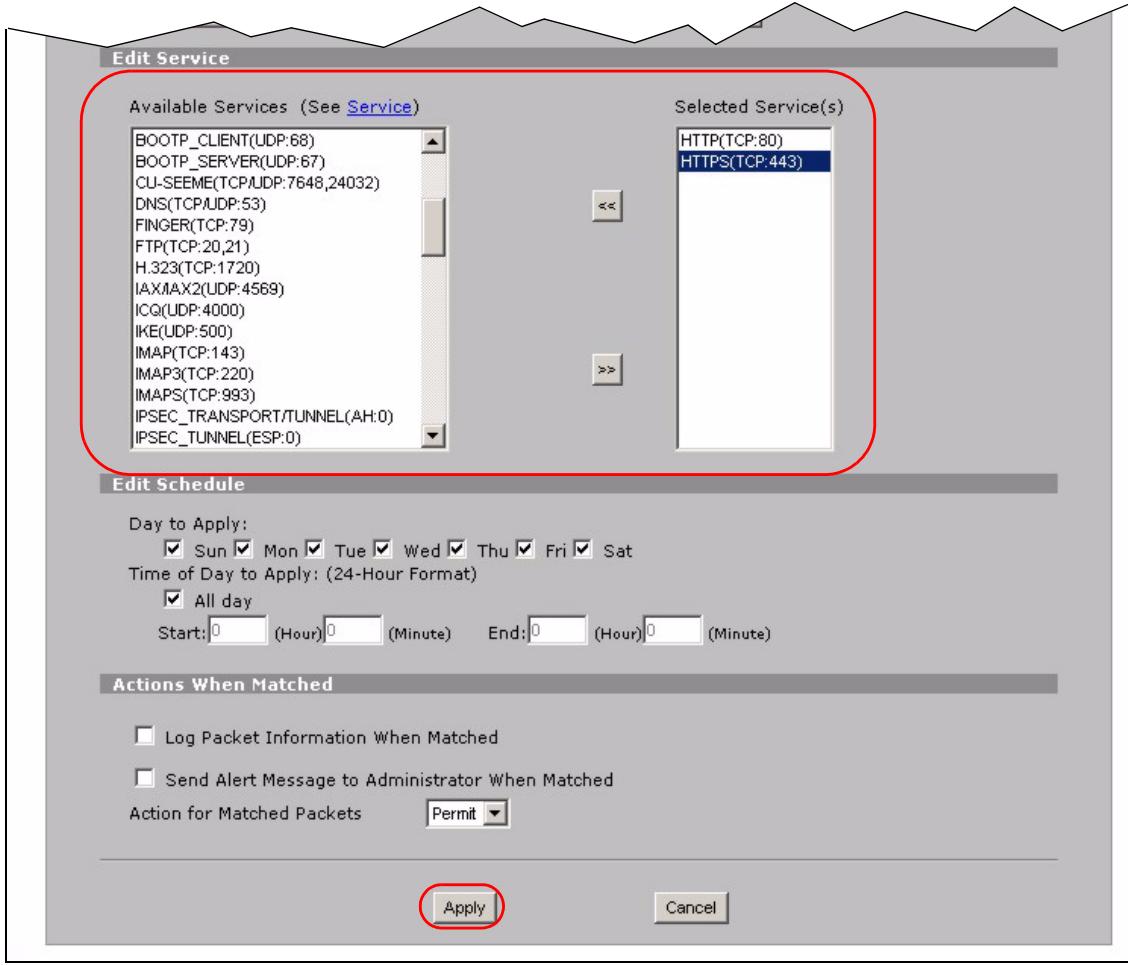
Figure 57 Tutorial Example: Firewall Rule: WAN to LAN Service Edit for Web Server
8 Click the insert icon to configure a firewall rule to allow traffic from the WAN to the mail server.
Enter a descriptive name (W-L_Mail for example).
Select Any in the Destination Address(es) box and click Delete.
Select Single Address as the destination address type. Enter 192.168.1.13 and click Add.
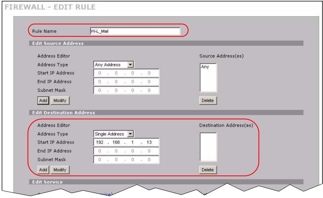
Figure 58 Tutorial Example: Firewall Rule: WAN to LAN Address Edit for Mail Server
9 Select Any(All) in the Available Services box on the left, and click >> to add it to the Selected Service(s) box on the right. Click Apply.
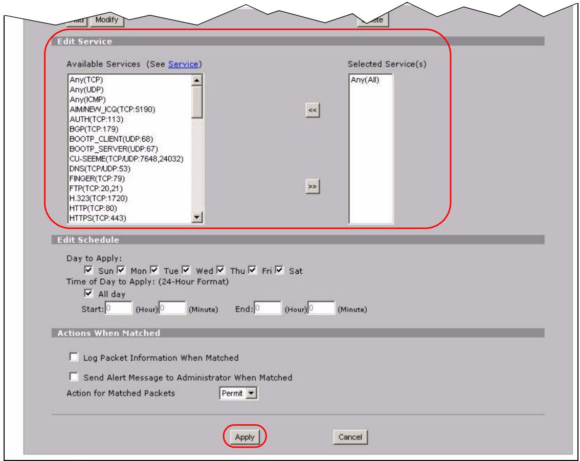
Figure 59 Tutorial Example: Firewall Rule: WAN to LAN Service Edit for Mail Server
10 Click the insert icon to configure a firewall rule to allow FTP traffic from the WAN to the FTP server.
Enter a descriptive name (W-L FTP for example).
Select Any in the Destination Address(es) box and click Delete.
Select Single Address as the destination address type. Enter 192.168.1.39 and click Add.
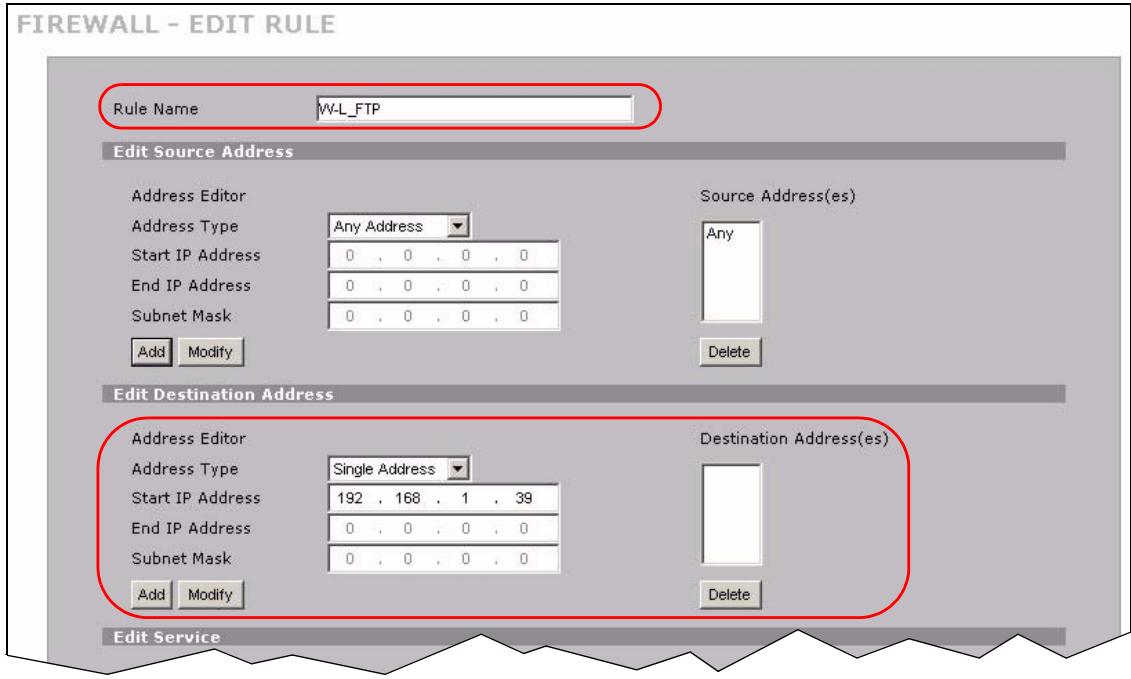
Figure 60 Tutorial Example: Firewall Rule: WAN to LAN Address Edit for FTP Server
11 Select FTP(TCP:20,21) in the Available Services box on the left, and click >> to add it to the Selected Service(s) box on the right. Click Apply.
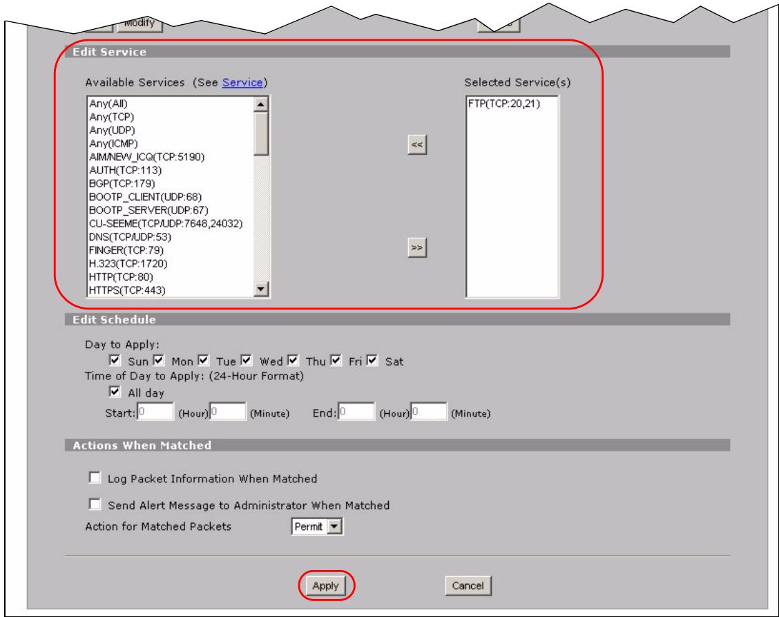
Figure 61 Tutorial Example: Firewall Rule: WAN to LAN Service Edit for FTP Server
12 When you are done, the Rule Summary screen looks as shown.
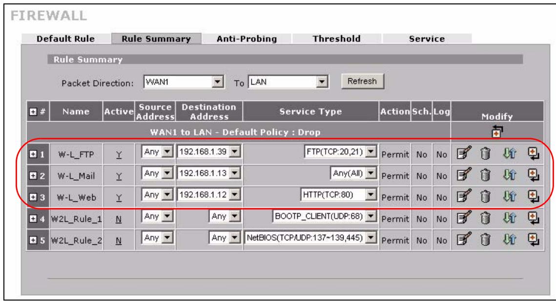
Figure 62 Tutorial Example: Firewall Rule Summary
4.5.6 Testing the Connections
1 Open the web browser on one of the local computers and enter any web site's URL in the address bar. If you can access the web site, your WAN 1 connection and NAT address mapping are configured successfully. If you cannot access it, make sure you entered the correct information in the WAN and NAT Address Mapping screens. Also check that the Internet account is active and the computer's IP address is in the same subnet as the ZyXEL Device.
2 Open your web browser and try accessing the web server (1.2.3.5) from the outside network. If you cannot access the web server, make sure the NAT address mapping rule is configured correctly and there is a firewall rule to allow HTTP traffic from the WAN to the web server.
3 Try accessing the FTP server (1.2.3.4) from the outside network to send or retrieve a file. If you cannot access the FTP server, make sure the NAT port forwarding rule is active and there is a firewall rule to allow FTP traffic from the WAN to FTP server.
4.6 Using NAT with Multiple Game Players
If two users (behind the ZyXEL Device) want to connect to the same server to play online games at the same time, but the server does not allow more than one login from the same IP address, you can configure a many-to-many rule instead of a many-to-one rule.
In this example, you have four static IP addresses (1.2.3.4 to 1.2.3.7) from your ISP. After you set up your WAN connection (see Section 4.5.2 on page 78), use the NAT > Address Mapping screen to map the third and forth public IP addresses to the mail server (192.168.1.12) and web server (192.168.1.13) respectively. The first and second public IP addresses are mapped to other outgoing LAN traffic. See Section 4.5.3 on page 82 for more information about IP address mapping.
When you finish configuration, the screen looks as shown.
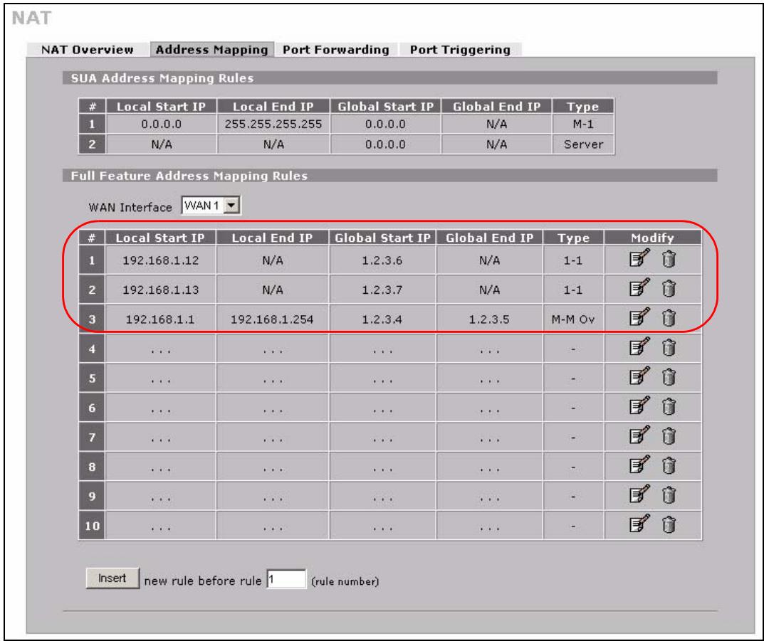
Figure 63 Tutorial Example: NAT Address Mapping Done: Game Playing

To allow traffic from the WAN to be forwarded through the ZyXEL Device, you must also create a firewall rule. Refer to Section 4.5.5 on page 89 for more information.
PART II
Network
LAN Screens (101)
WAN Screens (111)
DMZ Screens (135)
This chapter describes how to configure LAN settings.
5.1 LAN, WAN and the ZyXEL Device
A network is a shared communication system to which many computers are attached.
The Local Area Network (LAN) includes the computers and networking devices in your home or office that you connect to the ZyXEL Device's LAN ports.
The Wide Area Network (WAN) is another network (most likely the Internet) that you connect to the ZyXEL Device's WAN port. See Chapter 6 on page 111 for how to use the WAN screens to set up your WAN connection.
The LAN and the WAN are two separate networks. The ZyXEL Device controls the traffic that goes between them. The following graphic gives an example.
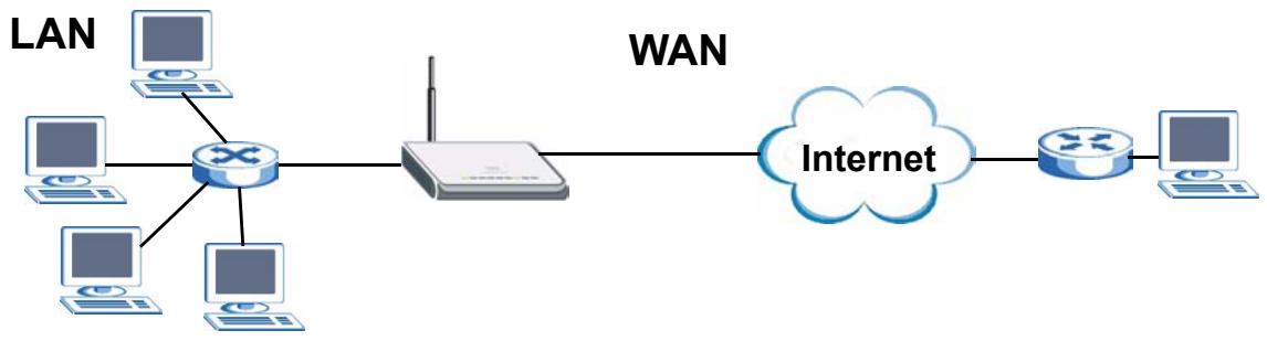
Figure 64 LAN and WAN
5.2 IP Address and Subnet Mask
Similar to the way houses on a street share a common street name, so too do computers on a LAN share one common network number.
Where you obtain your network number depends on your particular situation. If the ISP or your network administrator assigns you a block of registered IP addresses, follow their instructions in selecting the IP addresses and the subnet mask.
If the ISP did not explicitly give you an IP network number, then most likely you have a single user account and the ISP will assign you a dynamic IP address when the connection is established. If this is the case, it is recommended that you select a network number from 192.168.0.0 to 192.168.255.0 and you must enable the Network Address Translation (NAT)
feature of the ZyXEL Device. The Internet Assigned Number Authority (IANA) reserved this block of addresses specifically for private use; please do not use any other number unless you are told otherwise. If you select 192.168.1.0 as the network number; it covers 254 individual addresses, from 192.168.1.1 to 192.168.1.254 (zero and 255 are reserved). In other words, the first three numbers specify the network number while the last number identifies an individual computer on that network.
Once you have decided on the network number, pick an IP address that is easy to remember, for instance, 192.168.1.1, for your ZyXEL Device, but make sure that no other device on your network is using that IP address.
The subnet mask specifies the network number portion of an IP address. Your ZyXEL Device will compute the subnet mask automatically based on the IP address that you entered. You don't need to change the subnet mask computed by the ZyXEL Device unless you are instructed to do otherwise.
5.2.1 Private IP Addresses
Every machine on the Internet must have a unique address. If your networks are isolated from the Internet, for example, only between your two branch offices, you can assign any IP addresses to the hosts without problems. However, the Internet Assigned Numbers Authority (IANA) has reserved the following three blocks of IP addresses specifically for private networks:
10.0.0.0 10.255.255.255
172.16.0.0 — 172.31.255.255
192.168.0.0-192.168.255.255
You can obtain your IP address from the IANA, from an ISP or it can be assigned from a private network. If you belong to a small organization and your Internet access is through an ISP, the ISP can provide you with the Internet addresses for your local networks. On the other hand, if you are part of a much larger organization, you should consult your network administrator for the appropriate IP addresses.

Regardless of your particular situation, do not create an arbitrary IP address; always follow the guidelines above. For more information on address assignment, please refer to RFC 1597, Address Allocation for Private Intermets and RFC 1466, Guidelines for Management of IP Address Space.
5.3 DHCP
The ZyXEL Device can use DHCP (Dynamic Host Configuration Protocol, RFC 2131 and RFC 2132) to automatically assign IP addresses subnet masks, gateways, and some network information like the IP addresses of DNS servers to the computers on your LAN. You can alternatively have the ZyXEL Device relay DHCP information from another DHCP server. If you disable the ZyXEL Device's DHCP service, you must have another DHCP server on your LAN, or else the computers must be manually configured.
5.3.1 IP Pool Setup
The ZyXEL Device is pre-configured with a pool of IP addresses for the computers on your LAN. See Chapter 22 on page 345 for the default IP pool range. Do not assign your LAN computers static IP addresses that are in the DHCP pool.
5.4 RIP Setup
RIP (Routing Information Protocol, RFC 1058 and RFC 1389) allows a router to exchange routing information with other routers. RIP Direction controls the sending and receiving of RIP packets. When set to Both or Out Only, the ZyXEL Device will broadcast its routing table periodically. When set to Both or In Only, it will incorporate the RIP information that it receives; when set to None, it will not send any RIP packets and will ignore any RIP packets received.
RIP Version controls the format and the broadcasting method of the RIP packets that the ZyXEL Device sends (it recognizes both formats when receiving). RIP-1 is universally supported; but RIP-2 carries more information. RIP-1 is probably adequate for most networks, unless you have an unusual network topology.
Both RIP-2B and RIP-2M send routing data in RIP-2 format; the difference being that RIP-2B uses subnet broadcasting while RIP-2M uses multicast. Multicast can reduce the load on non-router machines since they generally do not listen to the RIP multicast address and so will not receive the RIP packets. However, if one router uses multicast, then all routers on your network must use multicast, also.
By default, RIP Direction is set to Both and RIP Version to RIP-1.
5.5 Multicast
Traditionally, IP packets are transmitted in one of either two ways - Unicast (1 sender - 1 recipient) or Broadcast (1 sender - everybody on the network). Multicast delivers IP packets to a group of hosts on the network - not everybody and not just 1.
IGMP (Internet Group Multicast Protocol) is a network-layer protocol used to establish membership in a Multicast group - it is not used to carry user data. IGMP version 2 (RFC 2236) is an improvement over version 1 (RFC 1112) but IGMP version 1 is still in wide use. If you would like to read more detailed information about interoperability between IGMP version 2 and version 1, please see sections 4 and 5 of RFC 2236. The class D IP address is used to identify host groups and can be in the range 224.0.0.0 to 239.255.255.255. The address 224.0.0.0 is not assigned to any group and is used by IP multicast computers. The address 224.0.0.1 is used for query messages and is assigned to the permanent group of all IP hosts (including gateways). All hosts must join the 224.0.0.1 group in order to participate in IGMP. The address 224.0.0.2 is assigned to the multicast routers group.
The ZyXEL Device supports both IGMP version 1 (IGMP-v1) and IGMP version 2 (IGMP-v2). At start up, the ZyXEL Device queries all directly connected networks to gather group membership. After that, the ZyXEL Device periodically updates this information. IP multicasting can be enabled/disabled on the ZyXEL Device LAN and/or WAN interfaces in the web configurator (LAN; WAN). Select None to disable IP multicasting on these interfaces.
5.6 WINS
WINS (Windows Internet Naming Service) is a Windows implementation of NetBIOS Name Server (NBNS) on Windows. It keeps track of NetBIOS computer names. It stores a mapping table of your network's computer names and IP addresses. The table is dynamically updated for IP addresses assigned by DHCP. This helps reduce broadcast traffic since computers can query the server instead of broadcasting a request for a computer name's IP address. In this way WINS is similar to DNS, although WINS does not use a hierarchy (unlike DNS). A network can have more than one WINS server. Samba can also serve as a WINS server.
5.7 LAN
Click NETWORK > LAN to open the LAN screen. Use this screen to configure the ZyXEL Device's IP address and other LAN TCP/IP settings as well as the built-in DHCP server capability that assigns IP addresses and DNS servers to systems that support DHCP client capability.
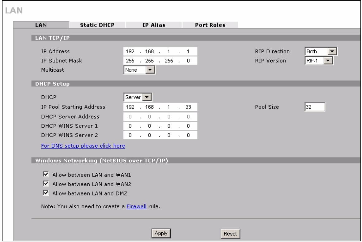
Figure 65 NETWORK > LAN
The following table describes the labels in this screen.
Table 12 NETWORK > LAN
| LABEL | DESCRIPTION |
| LAN TCP/IP | |
| IP Address | Type the IP address of your ZyXEL Device in dotted decimal notation. 192.168.1.1 is the factory default. Alternatively, click the right mouse button to copy and/or paste the IP address. |
| IP Subnet Mask | The subnet mask specifies the network number portion of an IP address. Your ZyXEL Device automatically calculates the subnet mask based on the IP address that you assign. Unless you are implementing subnetting, use the subnet mask computed by the ZyXEL Device. |
| RIP Direction | RIP (Routing Information Protocol, RFC1058 and RFC 1389) allows a router to exchange routing information with other routers. The RIP Direction field controls the sending and receiving of RIP packets. Select the RIP direction from Both/In Only/Out Only/None. When set to Both or Out Only, the ZyXEL Device will broadcast its routing table periodically. When set to Both or In Only, it will incorporate the RIP information that it receives; when set to None, it will not send any RIP packets and will ignore any RIP packets received. Both is the default. |
| RIP Version | The RIP Version field controls the format and the broadcasting method of the RIP packets that the ZyXEL Device sends (it recognizes both formats when receiving). RIP-1 is universally supported but RIP-2 carries more information. RIP-1 is probably adequate for most networks, unless you have an unusual network topology. Both RIP-2B and RIP-2M sends the routing data in RIP-2 format; the difference being that RIP-2B uses subnet broadcasting while RIP-2M uses multicast. Multicast can reduce the load on non-router machines since they generally do not listen to the RIP multicast address and so will not receive the RIP packets. However, if one router uses multicast, then all routers on your network must use multicast, also. By default, RIP direction is set to Both and the Version set to RIP-1. |
| Multicast | Select IGMP V-1 or IGMP V-2 or None. IGMP (Internet Group Multicast Protocol) is a network-layer protocol used to establish membership in a Multicast group - it is not used to carry user data. IGMP version 2 (RFC 2236) is an improvement over version 1 (RFC 1112) but IGMP version 1 is still in wide use. If you would like to read more detailed information about interoperability between IGMP version 2 and version 1, please see sections 4 and 5 of RFC 2236. |
| DHCP Setup | |
| DHCP | DHCP (Dynamic Host Configuration Protocol, RFC 2131 and RFC 2132) allows individual clients (workstations) to obtain TCP/IP configuration at startup from a server. Unless you are instructed by your ISP, leave this field set to Server. When configured as a server, the ZyXEL Device provides TCP/IP configuration for the clients. When set as a server, fill in the IP Pool Starting Address and Pool Size fields. Select Relay to have the ZyXEL Device forward DHCP requests to another DHCP server. When set to Relay, fill in the DHCP Server Address field. Select None to stop the ZyXEL Device from acting as a DHCP server. When you select None, you must have another DHCP server on your LAN, or else the computers must be manually configured. |
| IP Pool Starting Address | This field specifies the first of the contiguous addresses in the IP address pool. |
| Pool Size | This field specifies the size, or count of the IP address pool. |
| DHCP Server Address | Type the IP address of the DHCP server to which you want the ZyXEL Device to relay DHCP requests. Use dotted decimal notation. Alternatively, click the right mouse button to copy and/or paste the IP address. |
| DHCP WINS Server 1, 2 | Type the IP address of the WINS (Windows Internet Naming Service) server that you want to send to the DHCP clients. The WINS server keeps a mapping table of the computer names on your network and the IP addresses that they are currently using. |
| Windows Networking (NetBIOS over TCP/IP) | NetBIOS (Network Basic Input/Output System) are TCP or UDP packets that enable a computer to connect to and communicate with a LAN. For some dial-up services such as PPPoE or PPTP, NetBIOS packets cause unwanted calls. However it may sometimes be necessary to allow NetBIOS packets to pass through to the WAN in order to find a computer on the WAN. |
| Allow between LAN and WAN1 | Select this check box to forward NetBIOS packets from the LAN to WAN 1 and from WAN 1 to the LAN. If your firewall is enabled with the default policy set to block WAN 1 to LAN traffic, you also need to enable the default WAN 1 to LAN firewall rule that forwards NetBIOS traffic.Clear this check box to block all NetBIOS packets going from the LAN to WAN 1 and from WAN 1 to the LAN. |
| Allow between LAN and WAN2 | Select this check box to forward NetBIOS packets from the LAN to WAN 2 and from WAN 2 to the LAN. If your firewall is enabled with the default policy set to block WAN 2 to LAN traffic, you also need to enable the default WAN 2 to LANfirewall rule that forwards NetBIOS traffic.Clear this check box to block all NetBIOS packets going from the LAN to WAN 2 and from WAN 2 to the LAN. |
| Allow between LAN and DMZ | Select this check box to forward NetBIOS packets from the LAN to the DMZ and from the DMZ to the LAN. If your firewall is enabled with the default policy set to block DMZ to LAN traffic, you also need to enable the default DMZ to LAN firewall rule that forwards NetBIOS traffic.Clear this check box to block all NetBIOS packets going from the LAN to the DMZ and from the DMZ to the LAN. |
| Apply | Click Apply to save your changes. |
| Reset | Click Reset to begin configuring this screen afresh. |
5.8 LAN Static DHCP
This table allows you to assign IP addresses on the LAN to specific individual computers based on their MAC Addresses.
Every Ethernet device has a unique MAC (Media Access Control) address. The MAC address is assigned at the factory and consists of six pairs of hexadecimal characters, for example, 00:A0:C5:00:00:02.
To change your ZyXEL Device's static DHCP settings, click NETWORK > LAN > Static DHCP. The screen appears as shown.
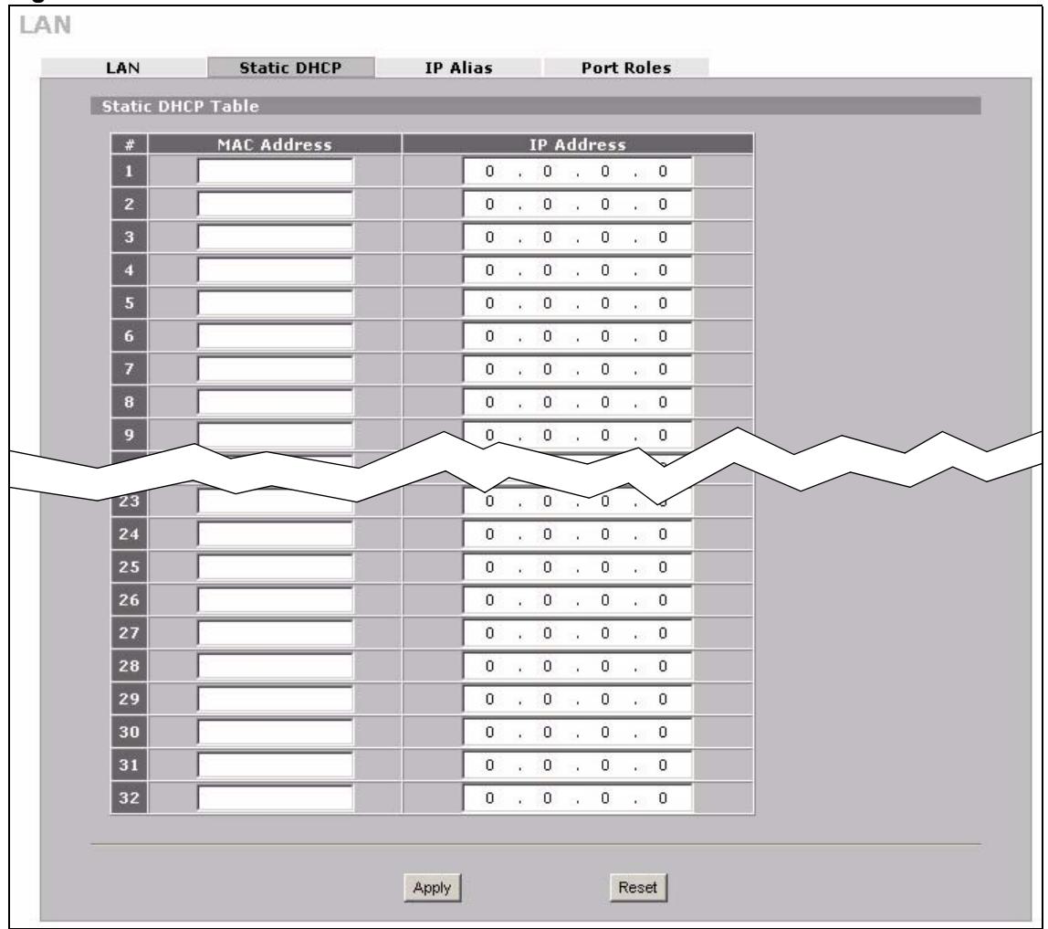
Figure 66 NETWORK > LAN > Static DHCP
The following table describes the labels in this screen.
Table 13 NETWORK > LAN > Static DHCP
| LABEL | DESCRIPTION |
| # | This is the index number of the Static IP table entry (row). |
| MAC Address | Type the MAC address of a computer on your LAN. |
| IP Address | Type the IP address that you want to assign to the computer on your LAN. Alternatively, click the right mouse button to copy and/or paste the IP address. |
| Apply | Click Apply to save your changes. |
| Reset | Click Reset to begin configuring this screen afresh. |
5.9 LAN IP Alias
IP alias allows you to partition a physical network into different logical networks over the same Ethernet interface.
The ZyXEL Device has a single LAN interface. Even though more than one of ports 1 4 may be in the LAN port role, they are all still part of a single physical Ethernet interface and all use the same IP address.
The ZyXEL Device supports three logical LAN interfaces via its single physical LAN Ethernet interface. The ZyXEL Device itself is the gateway for each of the logical LAN networks.
When you use IP alias, you can also configure firewall rules to control access between the LAN's logical networks (subnets).

Make sure that the subnets of the logical networks do not overlap.
The following figure shows a LAN divided into subnets A, B, and C.
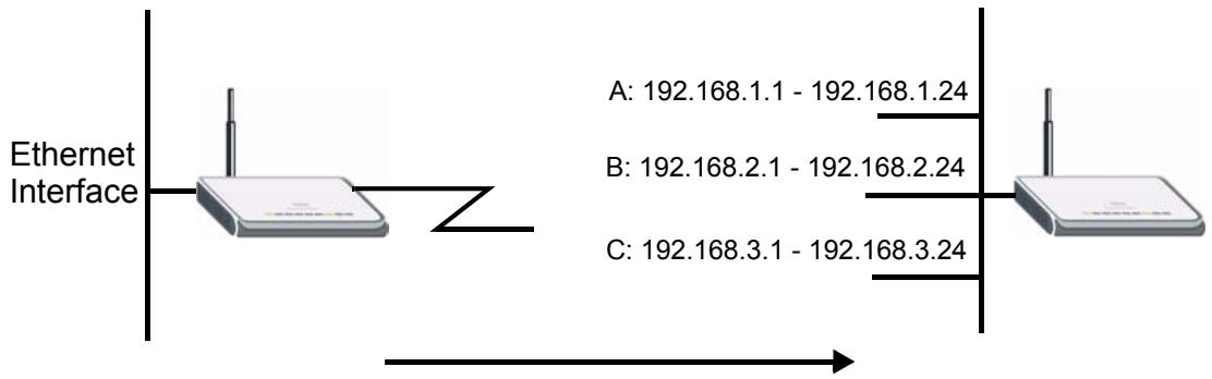
Figure 67 Physical Network & Partitioned Logical Networks
To change your ZyXEL Device's IP alias settings, click NETWORK > LAN > IP Alias. The screen appears as shown.
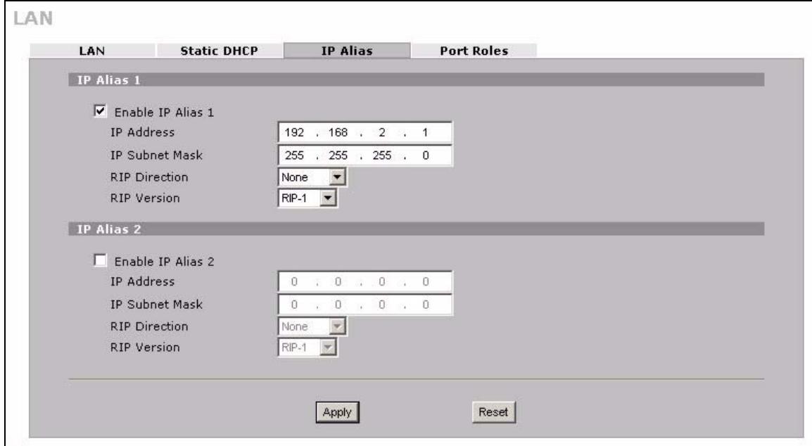
Figure 68 NETWORK > LAN > IP Alias
The following table describes the labels in this screen.
Table 14 NETWORK > LAN > IP Alias
| LABEL | DESCRIPTION |
| Enable IP Alias 1, 2 | Select the check box to configure another LAN network for the ZyXEL Device. |
| IP Address | Enter the IP address of your ZyXEL Device in dotted decimal notation. Alternatively, click the right mouse button to copy and/or paste the IP address. |
| IP Subnet Mask | Your ZyXEL Device will automatically calculate the subnet mask based on the IP address that you assign. Unless you are implementing subnetting, use the subnet mask computed by the ZyXEL Device. |
| RIP Direction | RIP (Routing Information Protocol, RFC 1058 and RFC 1389) allows a router to exchange routing information with other routers. The RIP Direction field controls the sending and receiving of RIP packets. Select the RIP direction from Both/In Only/Out Only/None. When set to Both or Out Only, the ZyXEL Device will broadcast its routing table periodically. When set to Both or In Only, it will incorporate the RIP information that it receives; when set to None, it will not send any RIP packets and will ignore any RIP packets received. |
| RIP Version | The RIP Version field controls the format and the broadcasting method of the RIP packets that the ZyXEL Device sends (it recognizes both formats when receiving). RIP-1 is universally supported but RIP-2 carries more information. RIP-1 is probably adequate for most networks, unless you have an unusual network topology. Both RIP-2B and RIP-2M sends the routing data in RIP-2 format; the difference being that RIP-2B uses subnet broadcasting while RIP-2M uses multicasting. Multicasting can reduce the load on non-router machines since they generally do not listen to the RIP multicast address and so will not receive the RIP packets. However, if one router uses multicastasting, then all routers on your network must use multicastasting, also. By default, RIP direction is set to Both and the Version set to RIP-1. |
| Apply | Click Apply to save your changes. |
| Reset | Click Reset to begin configuring this screen afresh. |
5.10 LAN Port Roles
Use the Port Roles screen to set ports as part of the LAN or DMZ interface.
Ports 1~4 on the ZyXEL Device can be part of the LAN or DMZ interface.

Do the following if you are configuring from a computer connected to a LAN or DMZ port and changing the port's role:
1 A port's IP address varies as its role changes, make sure your computer's IP address is in the same subnet as the ZyXEL Device's LAN or DMZ IP address.
2 Use the appropriate LAN or DMZ IP address to access the ZyXEL Device.
To change your ZyXEL Device's port role settings, click NETWORK > LAN > Port Roles. The screen appears as shown.
The radio buttons correspond to Ethernet ports on the front panel of the ZyXEL Device. On the ZyXEL Device, ports 1 to 4 are all LAN ports by default.

Your changes are also reflected in the DMZ Port Roles screen.
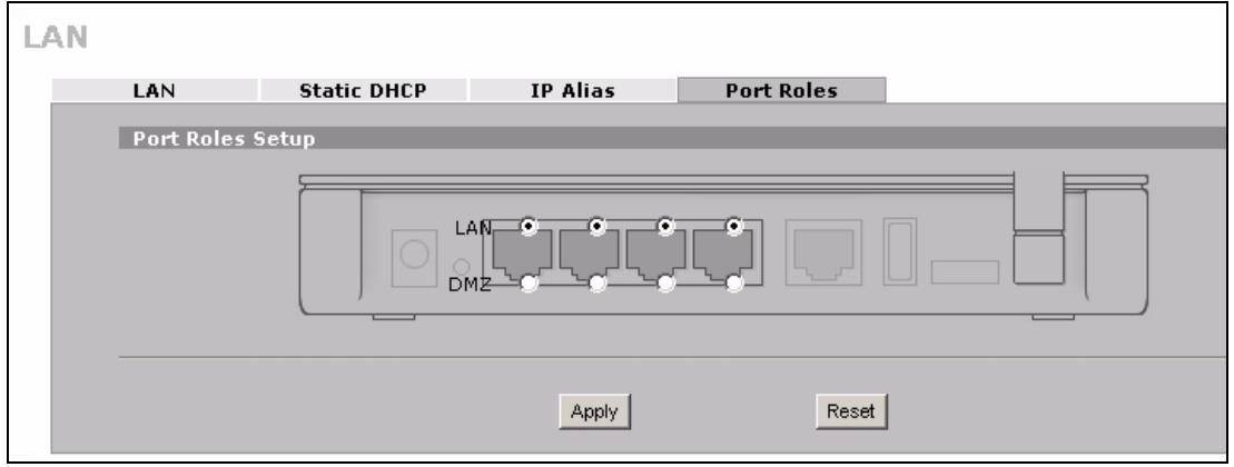
Figure 69 NETWORK > LAN > Port Roles
The following table describes the labels in this screen.
Table 15 NETWORK > LAN > Port Roles
| LABEL | DESCRIPTION |
| LAN | Select a port's LAN radio button to use the port as part of the LAN. The port will use the ZyXEL Device's LAN IP address and MAC address. |
| DMZ | Select a port's DMZ radio button to use the port as part of the DMZ. The port will use the ZyXEL Device's DMZ IP address and MAC address. |
| Apply | Click Apply to save your changes. |
| Reset | Click Reset to begin configuring this screen afresh. |
After you change the LAN or DMZ port roles and click Apply, please wait for few seconds until the following screen appears. Click Return to go back to the Port Roles screen.
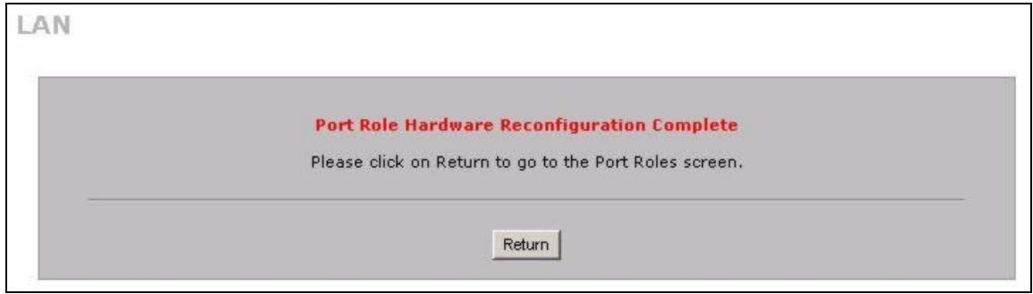
Figure 70 Port Roles Change Complete
WAN Screens
This chapter describes how to configure WAN settings.

WAN 2 refers to the 3G card on the supported ZyXEL Device.
6.1 WAN Overview
- Use the WAN General screen to configure operation mode, route priority and connection test for the ZyXEL Device.
- Use the WAN 1 screen to configure the WAN1 interface for Internet access on the ZyXEL Device.
- Use the 3G (WAN 2) screen to configure the WAN2 interface for Internet access on the ZyXEL Device.
- Use the Traffic Redirect screen to configure an alternative gateway.
6.2 Multiple WAN
You can use a second connection as a backup to enhance network reliability.
The ZyXEL Device has two WAN ports. You can optionally activate the internal 3G card to use the second 3G WAN interface. You can connect one interface to one ISP (or network) and connect the other to a second ISP (or network).
The ZyXEL Device's NAT feature allows you to configure sets of rules for one WAN interface and separate sets of rules for the other WAN interface. Refer to Chapter 12 on page 225 for details.
You can select through which WAN interface you want to send out traffic from UPnP-enabled applications (see Chapter 16 on page 281).
The ZyXEL Device's DDNS lets you select which WAN interface you want to use for each individual domain name. The DDNS high availability feature lets you have the ZyXEL Device use the other WAN interface for a domain name if the configured WAN interface's connection goes down. See Section 14.10.2 on page 256 for details.
6.3 TCP/IP Priority (Metric)
The metric represents the "cost of transmission". A router determines the best route for transmission by choosing a path with the lowest "cost". RIP routing uses hop count as the measurement of cost, with a minimum of "1" for directly connected networks. The number must be between "1" and "15"; a number greater than "15" means the link is down. The smaller the number, the lower the "cost".
1 The metric sets the priority for the ZyXEL Device's routes to the Internet. Each route must have a unique metric.
2 The priorities of the WAN interface routes must always be higher than the traffic redirect route priorities.
Lets say that you have the WAN operation mode set to active/passive, meaning the ZyXEL Device use the second highest priority WAN interface as a back up. The WAN 1 route has a metric of "2", the WAN 2 route has a metric of "3", and the traffic-direct route has a metric of "14". In this case, the WAN 1 route acts as the primary default route. If the WAN 1 route fails to connect to the Internet, the ZyXEL Device tries the WAN 2 route next. If the WAN 2 route fails, the ZyXEL Device tries the traffic-direct route.
The traffic redirect route cannot take priority over the WAN 1 and WAN 2 routes.
6.4 WAN General
Click NETWORK > WAN to open the General screen. Use this screen to configure operation mode, route priority and connection test.

WAN 2 refers to the 3G card on the supported ZyXEL Device.
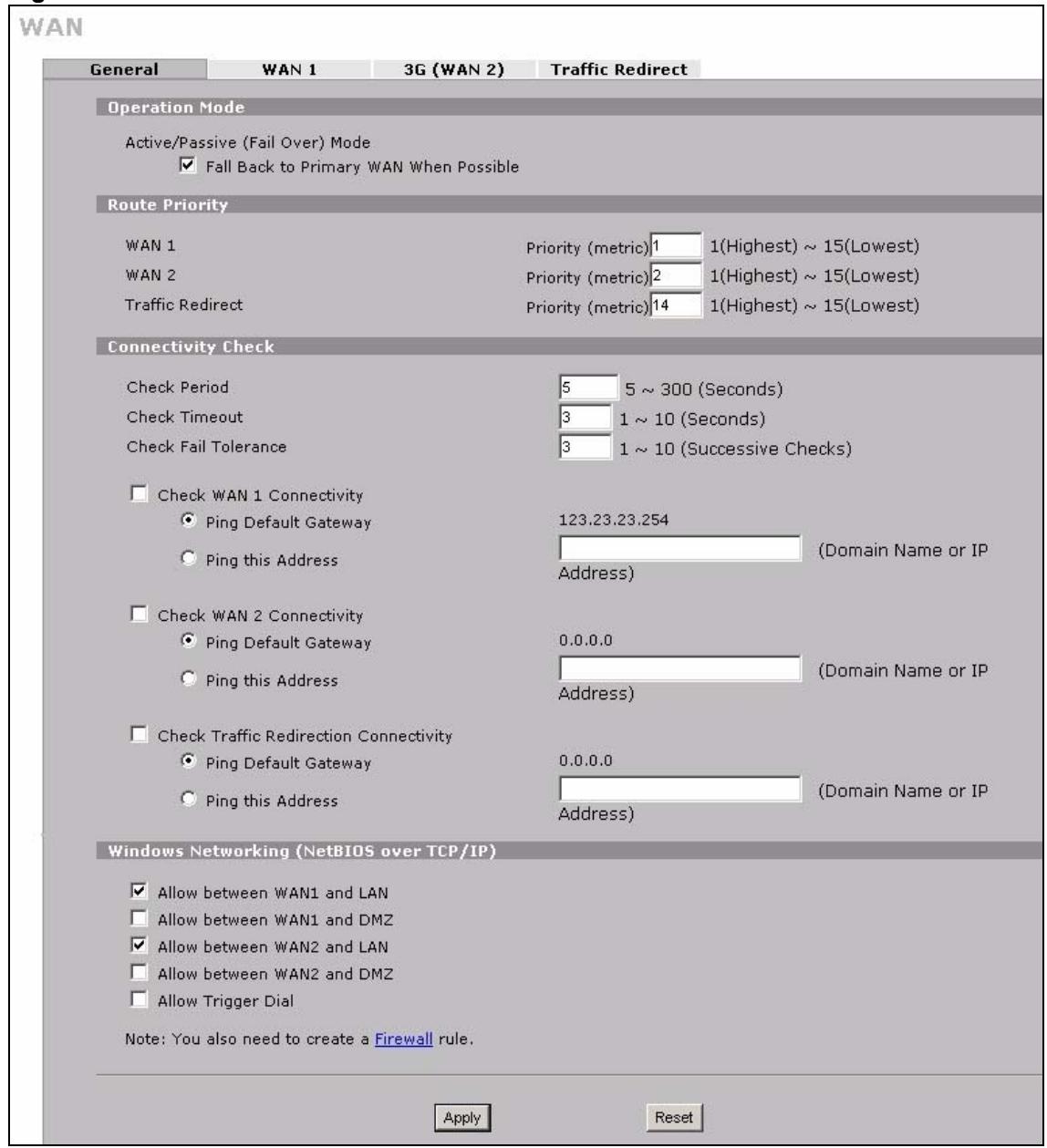
Figure 71 NETWORK > WAN General
The following table describes the labels in this screen.
Table 16 NETWORK > WAN General
| LABEL | DESCRIPTION |
| Active/Passive(Fail Over) Mode | The ZyXEL Device uses the second highest priority WAN interface as a back up. This means that the ZyXEL Device will normally use the highest priority (primary) WAN interface (depending on the priorities you configure in the Route Priority fields). The ZyXEL Device will switch to the secondary (second highest priority) WAN interface when the primary WAN interface's connection fails. |
| Fall Back to Primary WAN When Possible | This field determines the action the ZyXEL Device takes after the primary WAN interface fails and the ZyXEL Device starts using the secondary WAN interface. Select this check box to have the ZyXEL Device change back to using the primary WAN interface when the ZyXEL Device can connect through the primary WAN interface again.Clear this check box to have the ZyXEL Device continue using the secondary WAN interface, even after the ZyXEL Device can connect through the primary WAN interface again. The ZyXEL Device continues to use the secondary WAN interface until it's connection fails (at which time it will change back to using the primary WAN interface if its connection is up. |
| Route Priority | |
| WAN1WAN2Traffic Redirect | The default WAN connection is “1” as your broadband connection via the WAN interface should always be your preferred method of accessing the WAN. The ZyXEL Device switches from WAN interface 1 to WAN interface 2 if WAN interface 1's connection fails and then back to WAN interface 1 when WAN interface 1's connection comes back up. The default priority of the routes is WAN 1, WAN 2 and then Traffic Redirect:You have two choices for an auxiliary connection (WAN 2 and Traffic Redirect) in the event that your regular WAN connection goes down. |
| ConnectivityCheck | |
| Check Period | The ZyXEL Device tests a WAN connection by periodically sending a ping to either the default gateway or the address in the Ping this Address field.Type a number of seconds (5 to 300) to set the time interval between checks. Allow more time if your destination IP address handles lots of traffic. |
| Check Timeout | Type the number of seconds (1 to 10) for your ZyXEL Device to wait for a response to the ping before considering the check to have failed. This setting must be less than the Check Period. Use a higher value in this field if your network is busy or congested. |
| Check FailTolerance | Type how many WAN connection checks can fail (1-10) before the connection is considered "down" (not connected). The ZyXEL Device still checks a "down" connection to detect if it reconnects. |
| Check WAN1/2 Connectivity | Select the check box to have the ZyXEL Device periodically test the respective WAN interface's connection.Select Ping Default Gateway to have the ZyXEL Device ping the WAN interface's default gateway IP address.Select Ping this Address and enter a domain name or IP address of a reliable nearby computer (for example, your ISP's DNS server address) to have the ZyXEL Device ping that address. For a domain name, use up to 63 alphanumeric characters (hyphens, periods and the underscore are also allowed) without spaces. |
| Check Traffic Redirection Connectivity | Select the check box to have the ZyXEL Device periodically test the traffic redirect connection. Select Ping Default Gateway to have the ZyXEL Device ping the backup gateway's IP address. Select Ping this Address and enter a domain name or IP address of a reliable nearby computer (for example, your ISP's DNS server address) to have the ZyXEL Device ping that address. For a domain name, use up to 63 alphanumeric characters (hyphens, periods and the underscore are also allowed) without spaces. |
| Windows Networking (NetBIOS over TCP/IP) | NetBIOS (Network Basic Input/Output System) are TCP or UDP packets that enable a computer to connect to and communicate with a LAN. For some dial-up services such as PPPoE or PPTP, NetBIOS packets cause unwanted calls. |
| Allow between WAN1 and LAN | Select this check box to forward NetBIOS packets from WAN 1 to the LAN port and from the LAN port to WAN1. If your firewall is enabled with the default policy set to block WAN 1 to LAN traffic, you also need to enable the default WAN1 to LAN firewall rule that forwards NetBIOS traffic.Clear this check box to block all NetBIOS packets going from WAN 1 to the LAN port and from LAN port to WAN1. |
| Allow between WAN1 and DMZ | Select this check box to forward NetBIOS packets from WAN 1 to the DMZ port and from the DMZ port to WAN1.Clear this check box to block all NetBIOS packets going from WAN 1 to the DMZ port and from DMZ port to WAN1. |
| Allow between WAN2 and LAN | Select this check box to forward NetBIOS packets from WAN 2 to the LAN port and from the LAN port to WAN2. If your firewall is enabled with the default policy set to block WAN 2 to LAN traffic, you also need to enable the default WAN2 to LANfirewall rule that forwards NetBIOS traffic.Clear this check box to block all NetBIOS packets going from WAN 2 to the LAN port and from LAN port to WAN2. |
| Allow between WAN2 and DMZ | Select this check box to forward NetBIOS packets from WAN 2 to the DMZ port and from the DMZ port to WAN2.Clear this check box to block all NetBIOS packets going from WAN 2 to the DMZ port and from DMZ port to WAN2. |
| Allow Trigger Dial | Select this option to allow NetBIOS packets to initiate calls. |
| Apply | Click Apply to save your changes. |
| Reset | Click Reset to begin configuring this screen afresh. |
6.5 WAN IP Address Assignment
Every computer on the Internet must have a unique IP address. If your networks are isolated from the Internet, for instance, only between your two branch offices, you can assign any IP addresses to the hosts without problems. However, the Internet Assigned Numbers Authority (IANA) has reserved the following three blocks of IP addresses specifically for private networks.
Table 17 Private IP Address Ranges
| 10.0.0.0 | - | 10.255.255.255 |
| 172.16.0.0 | - | 172.31.255.255 |
| 192.168.0.0 | - | 192.168.255.255 |
You can obtain your IP address from the IANA, from an ISP or have it assigned by a private network. If you belong to a small organization and your Internet access is through an ISP, the ISP can provide you with the Internet addresses for your local networks. On the other hand, if you are part of a much larger organization, you should consult your network administrator for the appropriate IP addresses.

Regardless of your particular situation, do not create an arbitrary IP address; always follow the guidelines above. For more information on address assignment, please refer to RFC 1597, Address Allocation for Private Intermets and RFC 1466, Guidelines for Management of IP Address Space.
6.6 DNS Server Address Assignment
Use DNS (Domain Name System) to map a domain name to its corresponding IP address and vice versa, for instance, the IP address of www.zyxel.com is 204.217.0.2. The DNS server is extremely important because without it, you must know the IP address of a computer before you can access it.
The ZyXEL Device can get the DNS server addresses in the following ways.
1 The ISP tells you the DNS server addresses, usually in the form of an information sheet, when you sign up. If your ISP gives you DNS server addresses, manually enter them in the DNS server fields.
2 If your ISP dynamically assigns the DNS server IP addresses (along with the ZyXEL Device's WAN IP address), set the DNS server fields to get the DNS server address from the ISP.
3 You can manually enter the IP addresses of other DNS servers. These servers can be public or private. A DNS server could even be behind a remote IPSec router (see Section 14.5.1 on page 248).
6.7 WAN MAC Address
Every Ethernet device has a unique MAC (Media Access Control) address. The MAC address is assigned at the factory and consists of six pairs of hexadecimal characters, for example, 00:A0:C5:00:00:02.
You can configure the WAN port's MAC address by either using the factory default or cloning the MAC address from a computer on your LAN. Once it is successfully configured, the address will be copied to the "rom" file (ZyNOS configuration file). It will not change unless you change the setting or upload a different "rom" file.
6.8 WAN 1
Use this screen to change your ZyXEL Device's WAN 1 ISP, IP and MAC settings. Click NETWORK > WAN > WAN 1 to display this screen. The screen differs by the encapsulation.

The WAN 1 and WAN 2 IP addresses of a ZyXEL Device with multiple WAN interfaces must be on different subnets.
6.8.1 WAN Ethernet Encapsulation
For ISPs (such as Telstra) that send UDP heartbeat packets to verify that the customer is still online, please create a WAN-to-WAN/ZyXEL Device firewall rule for those packets. Contact your ISP to find the correct port number.
The screen shown next is for Ethernet encapsulation.
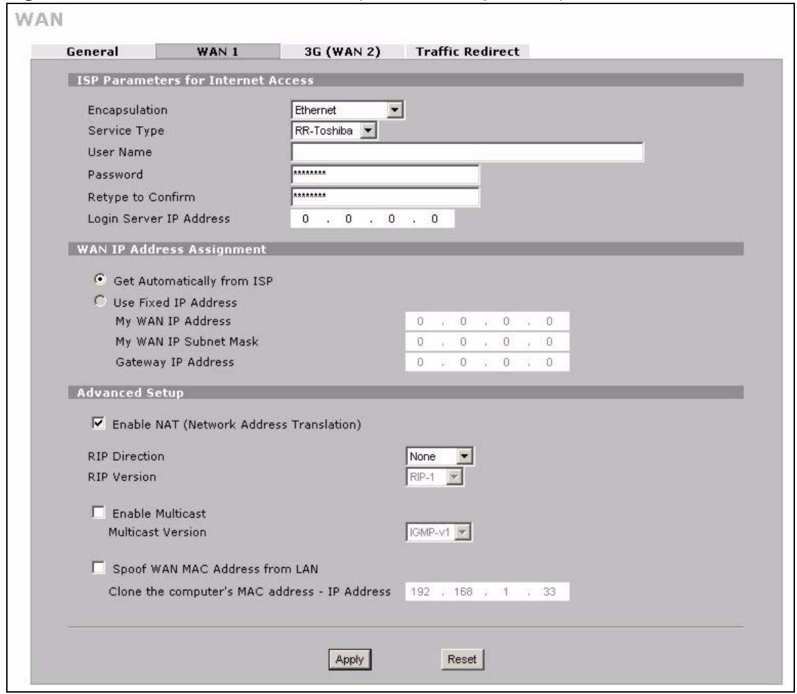
Figure 72 NETWORK > WAN > WAN 1 (Ethernet Encapsulation)
The following table describes the labels in this screen.
Table 18 NETWORK > WAN > WAN 1 (Ethernet Encapsulation)
| LABEL | DESCRIPTION |
| ISP Parameters for Internet Access | |
| Encapsulation | You must choose the Ethernet option when the WAN port is used as a regular Ethernet. |
| Service Type | Choose from Standard, Telstra (RoadRunner Telstra authentication method), RR-Manager (Roadrunner Manager authentication method), RR-Toshiba (Roadrunner Toshiba authentication method) or Telia Login. The following fields do not appear with the Standard service type. |
| UserID | Type the user name given to you by your ISP. |
| Password | Type the password associated with the user name above. |
| Retype to Confirm | Type your password again to make sure that you have entered is correctly. |
| Login Server IP Address | Type the authentication server IP address here if your ISP gave you one. This field is not available for Telia Login. |
| Login Server (Telia Login only) | Type the domain name of the Telia login server, for example login1.telia.com. |
| Reloggin Every(min) (Telia Login only) | The Telia server logs the ZyXEL Device out if the ZyXEL Device does not log in periodically. Type the number of minutes from 1 to 59 (30 default) for the ZyXEL Device to wait between logins. |
| WAN IP Address Assignment | |
| Get automatically from ISP | Select this option If your ISP did not assign you a fixed IP address. This is the default selection. |
| Use Fixed IP Address | Select this option If the ISP assigned a fixed IP address. |
| My WAN IP Address | Enter your WAN IP address in this field if you selected Use Fixed IP Address. |
| My WAN IP Subnet Mask | Enter the IP subnet mask (if your ISP gave you one) in this field if you selected Use Fixed IP Address. |
| Gateway IP Address | Enter the gateway IP address (if your ISP gave you one) in this field if you selected Use Fixed IP Address. |
| Advanced Setup | |
| Enable NAT (Network Address Translation) | Network Address Translation (NAT) allows the translation of an Internet protocol address used within one network (for example a private IP address used in a local network) to a different IP address known within another network (for example a public IP address used on the Internet). Select this check box to enable NAT. |
| RIP Direction | RIP (Routing Information Protocol) allows a router to exchange routing information with other routers. The RIP Direction field controls the sending and receiving of RIP packets.Choose Both, None, In Only or Out Only.When set to Both or Out Only, the ZyXEL Device will broadcast its routing table periodically.When set to Both or In Only, the ZyXEL Device will incorporate RIP information that it receives.When set to None, the ZyXEL Device will not send any RIP packets and will ignore any RIP packets received.By default, RIP Direction is set to Both. |
| RIP Version | The RIP Version field controls the format and the broadcasting method of the RIP packets that the ZyXEL Device sends (it recognizes both formats when receiving).Choose RIP-1, RIP-2B or RIP-2M.RIP-1 is universally supported; but RIP-2 carries more information. RIP-1 is probably adequate for most networks, unless you have an unusual network topology. Both RIP-2B and RIP-2M sends the routing data in RIP-2 format; the difference being that RIP-2B uses subnet broadcasting while RIP-2M uses multicast. Multicast can reduce the load on non-router machines since they generally do not listen to the RIP multicast address and so will not receive the RIP packets. However, if one router uses multicast, then all routers on your network must use multicast, also. By default, the RIP Version field is set to RIP-1. |
| Enable Multicast | Select this check box to turn on IGMP (Internet Group Multicast Protocol). IGMP is a network-layer protocol used to establish membership in a Multicast group - it is not used to carry user data. |
| Multicast Version | Choose None (default), IGMP-V1 or IGMP-V2. IGMP (Internet Group Multicast Protocol) is a session-layer protocol used to establish membership in a Multicast group - it is not used to carry user data. IGMP version 2 (RFC 2236) is an improvement over version 1 (RFC 1112) but IGMP version 1 is still in wide use. If you would like to read more detailed information about interoperability between IGMP version 2 and version 1, please see sections 4 and 5 of RFC 2236. |
| Spoof WAN MAC Address from LAN | You can configure the WAN port's MAC address by either using the factory assigned default MAC Address or cloning the MAC address of a computer on your LAN. By default, the ZyXEL Device uses the factory assigned MAC Address to identify itself on the WAN.Otherwise, select the check box next to Spoof WAN MAC Address from LAN and enter the IP address of the computer on the LAN whose MAC you are cloning.Once it is successfully configured, the address will be copied to the rom file (ZyNOS configuration file). It will not change unless you change the setting or upload a different ROM file. |
| Clone the computer's MAC address - IP Address | Enter the IP address of the computer on the LAN whose MAC you are cloning.If you clone the MAC address of a computer on your LAN, it is recommended that you clone the MAC address prior to hooking up the WAN port. |
| Apply | Click Apply to save your changes. |
| Reset | Click Reset to begin configuring this screen afresh. |
6.8.2 PPPoE Encapsulation
The ZyXEL Device supports PPPoE (Point-to-Point Protocol over Ethernet). PPPoE is an IETF standard (RFC 2516) specifying how a personal computer (PC) interacts with a broadband modem (DSL, cable, wireless, etc.) connection. The PPPoE option is for a dial-up connection using PPPoE.
For the service provider, PPPoE offers an access and authentication method that works with existing access control systems (for example RADIUS).
One of the benefits of PPPoE is the ability to let you access one of multiple network services, a function known as dynamic service selection. This enables the service provider to easily create and offer new IP services for individuals.
Operationally, PPPoE saves significant effort for both you and the ISP or carrier, as it requires no specific configuration of the broadband modem at the customer site.
By implementing PPPoE directly on the ZyXEL Device (rather than individual computers), the computers on the LAN do not need PPPoE software installed, since the ZyXEL Device does that part of the task. Furthermore, with NAT, all of the LANs' computers will have access.
The screen shown next is for PPPoE encapsulation.
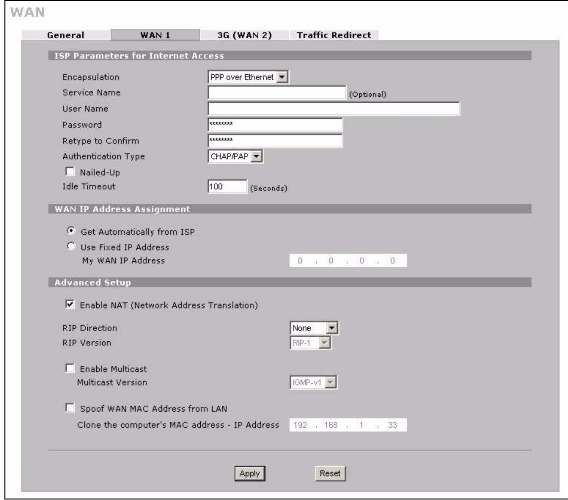
Figure 73 NETWORK > WAN > WAN 1 (PPPoE Encapsulation)
The following table describes the labels in this screen.
Table 19 NETWORK > WAN > WAN 1 (PPPoE Encapsulation)
| LABEL | DESCRIPTION |
| ISP Parameters for Internet Access | |
| Encapsulation | Select PPPoE for a dial-up connection using PPPoE. |
| Service Name | Type the PPPoE service name provided to you by your ISP. PPPoE uses a service name to identify and reach the PPPoE server. |
| User Name | Type the user name given to you by your ISP. |
| Password | Type the password associated with the user name above. |
| Retype to Confirm | Type your password again to make sure that you have entered is correctly. |
| Authentication Type | The ZyXEL Device supports PAP (Password Authentication Protocol) and CHAP (Challenge Handshake Authentication Protocol). CHAP is more secure than PAP; however, PAP is readily available on more platforms.Use the drop-down list box to select an authentication protocol for outgoing calls. Options are:CHAP/PAP - Your ZyXEL Device accepts either CHAP or PAP when requested by this remote node.CHAP - Your ZyXEL Device accepts CHAP only.PAP - Your ZyXEL Device accepts PAP only. |
| Nailed-Up | Select Nailed-Up if you do not want the connection to time out. |
| Idle Timeout | This value specifies the time in seconds that elapses before the ZyXEL Device automatically disconnects from the PPPoE server. |
| WAN IP Address Assignment | |
| Get automatically from ISP | Select this option If your ISP did not assign you a fixed IP address. This is the default selection. |
| Use Fixed IP Address | Select this option If the ISP assigned a fixed IP address. |
| My WAN IP Address | Enter your WAN IP address in this field if you selected Use Fixed IP Address. |
| Advanced Setup | |
| Enable NAT (Network Address Translation) | Network Address Translation (NAT) allows the translation of an Internet protocol address used within one network (for example a private IP address used in a local network) to a different IP address known within another network (for example a public IP address used on the Internet).Select this checkbox to enable NAT.For more information about NAT see Chapter 12 on page 225. |
| RIP Direction | RIP (Routing Information Protocol) allows a router to exchange routing information with other routers. The RIP Direction field controls the sending and receiving of RIP packets.Choose Both, None, In Only or Out Only.When set to Both or Out Only, the ZyXEL Device will broadcast its routing table periodically.When set to Both or In Only, the ZyXEL Device will incorporate RIP information that it receives.When set to None, the ZyXEL Device will not send any RIP packets and will ignore any RIP packets received.By default, RIP Direction is set to Both. |
| RIP Version | The RIP Version field controls the format and the broadcasting method of the RIP packets that the ZyXEL Device sends (it recognizes both formats when receiving). Choose RIP-1, RIP-2B or RIP-2M.RIP-1 is universally supported; but RIP-2 carries more information. RIP-1 is probably adequate for most networks, unless you have an unusual network topology. Both RIP-2B and RIP-2M sends the routing data in RIP-2 format; the difference being that RIP-2B uses subnet broadcasting while RIP-2M uses multicast. Multicasting can reduce the load on non-router machines since they generally do not listen to the RIP multicast address and so will not receive the RIP packets. However, if one router uses multicast, then all routers on your network must use multicast, also. By default, the RIP Version field is set to RIP-1. |
| Enable Multicast | Select this check box to turn on IGMP (Internet Group Multicast Protocol). IGMP is a network-layer protocol used to establish membership in a Multicast group - it is not used to carry user data. |
| Multicast Version | Choose None (default), IGMP-V1 or IGMP-V2. IGMP (Internet Group Multicast Protocol) is a session-layer protocol used to establish membership in a Multicast group - it is not used to carry user data. IGMP version 2 (RFC 2236) is an improvement over version 1 (RFC 1112) but IGMP version 1 is still in wide use. If you would like to read more detailed information about interoperability between IGMP version 2 and version 1, please see sections 4 and 5 of RFC 2236. |
| Spoof WAN MAC Address from LAN | You can configure the WAN port's MAC address by either using the factory assigned default MAC Address or cloning the MAC address of a computer on your LAN. By default, the ZyXEL Device uses the factory assigned MAC Address to identify itself on the WAN. Otherwise, select the check box next to Spoof WAN MAC Address from LAN and enter the IP address of the computer on the LAN whose MAC you are cloning. Once it is successfully configured, the address will be copied to the rom file (ZyNOS configuration file). It will not change unless you change the setting or upload a different ROM file. |
| Clone the computer's MAC address - IP Address | Enter the IP address of the computer on the LAN whose MAC you are cloning. If you clone the MAC address of a computer on your LAN, it is recommended that you clone the MAC address prior to hooking up the WAN port. |
| Apply | Click Apply to save your changes. |
| Reset | Click Reset to begin configuring this screen afresh. |
6.8.3 PPTP Encapsulation
Point-to-Point Tunneling Protocol (PPTP) is a network protocol that enables secure transfer of data from a remote client to a private server, creating a Virtual Private Network (VPN) using TCP/IP-based networks.
PPTP supports on-demand, multi-protocol and virtual private networking over public networks, such as the Internet. The screen shown next is for PPTP encapsulation.
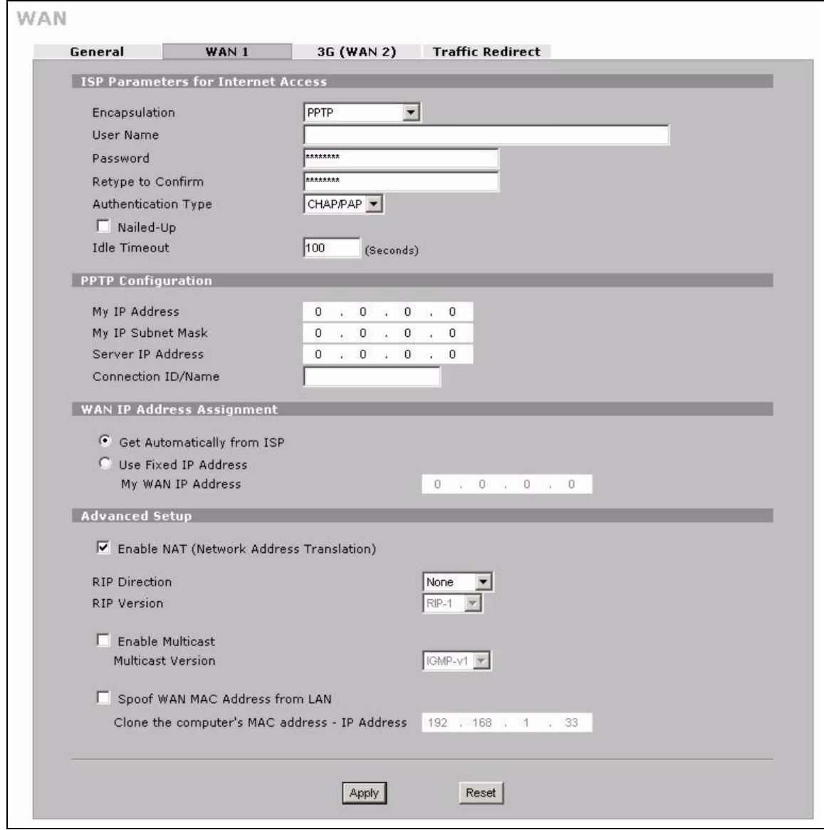
Figure 74 NETWORK > WAN > WAN 1 (PPTP Encapsulation)
The following table describes the labels in this screen.
Table 20 NETWORK > WAN > WAN 1 (PPTP Encapsulation)
| LABEL | DESCRIPTION |
| ISP Parameters for Internet Access | |
| Encapsulation | Set the encapsulation method to PPTP. The ZyXEL Device supports only one PPTP server connection at any given time. To configure a PPTP client, you must configure the User Name and Password fields for a PPP connection and the PPTP parameters for a PPTP connection. |
| User Name | Type the user name given to you by your ISP. |
| Password | Type the password associated with the user name above. |
| Retype to Confirm | Type your password again to make sure that you have entered it correctly. |
| Authentication Type | The ZyXEL Device supports PAP (Password Authentication Protocol) and CHAP (Challenge Handshake Authentication Protocol). CHAP is more secure than PAP; however, PAP is readily available on more platforms.Use the drop-down list box to select an authentication protocol for outgoing calls. Options are:CHAP/PAP - Your ZyXEL Device accepts either CHAP or PAP when requested by this remote node.CHAP - Your ZyXEL Device accepts CHAP only.PAP - Your ZyXEL Device accepts PAP only. |
| Nailed-up | Select Nailed-Up if you do not want the connection to time out. |
| Idle Timeout | This value specifies the time in seconds that elapses before the ZyXEL Device automatically disconnects from the PPTP server. |
| PPTP Configuration | |
| My IP Address | Type the (static) IP address assigned to you by your ISP. |
| My IP Subnet Mask | Your ZyXEL Device will automatically calculate the subnet mask based on the IP address that you assign. Unless you are implementing subnetting, use the subnet mask computed by the ZyXEL Device. |
| Server IP Address | Type the IP address of the PPTP server. |
| Connection ID/ Name | Type your identification name for the PPTP server. |
| WAN IP Address Assignment | |
| Get automatically from ISP | Select this option If your ISP did not assign you a fixed IP address. This is the default selection. |
| Use Fixed IP Address | Select this option If the ISP assigned a fixed IP address. |
| My WAN IP Address | Enter your WAN IP address in this field if you selected Use Fixed IP Address. |
| Advanced Setup | |
| Enable NAT (Network Address Translation) | Network Address Translation (NAT) allows the translation of an Internet protocol address used within one network (for example a private IP address used in a local network) to a different IP address known within another network (for example a public IP address used on the Internet).Select this checkbox to enable NAT.For more information about NAT see Chapter 12 on page 225. |
| RIP Direction | RIP (Routing Information Protocol) allows a router to exchange routing information with other routers. The RIP Direction field controls the sending and receiving of RIP packets.Choose Both, None, In Only or Out Only.When set to Both or Out Only, the ZyXEL Device will broadcast its routing table periodically.When set to Both or In Only, the ZyXEL Device will incorporate RIP information that it receives.When set to None, the ZyXEL Device will not send any RIP packets and will ignore any RIP packets received.By default, RIP Direction is set to Both. |
| RIP Version | The RIP Version field controls the format and the broadcasting method of the RIP packets that the ZyXEL Device sends (it recognizes both formats when receiving).Choose RIP-1, RIP-2B or RIP-2M.RIP-1 is universally supported; but RIP-2 carries more information. RIP-1 is probably adequate for most networks, unless you have an unusual network topology. Both RIP-2B and RIP-2M sends the routing data in RIP-2 format; the difference being that RIP-2B uses subnet broadcasting while RIP-2M uses multicast. Multicast can reduce the load on non-router machines since they generally do not listen to the RIP multicast address and so will not receive the RIP packets. However, if one router uses multicast, then all routers on your network must use multicast, also. By default, the RIP Version field is set to RIP-1. |
| Enable Multicast | Select this check box to turn on IGMP (Internet Group Multicast Protocol). IGMP is a network-layer protocol used to establish membership in a Multicast group - it is not used to carry user data. |
| Multicast Version | Choose None (default), IGMP-V1 or IGMP-V2. IGMP (Internet Group Multicast Protocol) is a session-layer protocol used to establish membership in a Multicast group - it is not used to carry user data. IGMP version 2 (RFC 2236) is an improvement over version 1 (RFC 1112) but IGMP version 1 is still in wide use. If you would like to read more detailed information about interoperability between IGMP version 2 and version 1, please see sections 4 and 5 of RFC 2236. |
| Spoof WAN MAC Address from LAN | You can configure the WAN port's MAC address by either using the factory assigned default MAC Address or cloning the MAC address of a computer on your LAN. By default, the ZyXEL Device uses the factory assigned MAC Address to identify itself on the WAN.Otherwise, select the check box next to Spoof WAN MAC Address from LAN and enter the IP address of the computer on the LAN whose MAC you are cloning. Once it is successfully configured, the address will be copied to the rom file (ZyNOS configuration file). It will not change unless you change the setting or upload a different ROM file. |
| Clone the computer's MAC address - IP Address | Enter the IP address of the computer on the LAN whose MAC you are cloning. If you clone the MAC address of a computer on your LAN, it is recommended that you clone the MAC address prior to hooking up the WAN port. |
| Apply | Click Apply to save your changes. |
| Reset | Click Reset to begin configuring this screen afresh. |
6.9 3G (WAN 2)
3G (Third Generation) is a digital, packet-switched wireless technology. Bandwidth usage is optimized as multiple users share the same channel and bandwidth is only allocated to users when they send data. It allows fast transfer of voice and non-voice data and provides broadband Internet access to mobile devices.

The actual data rate you obtain varies depending on your 3G card, the signal strength of the service provider's base station, your service plan, etc.

For NBG410W3G, you can use either the built-in 3G module or an external USB dongle to establish a 3G connection. Both connections cannot work simultaneously.
If the signal strength of a 3G network is too low, the 3G card may switch to an available 2.5G or 2.75G network. See the following table for a comparison between 2G, 2.5G, 2.75G, 3G and 3.5G wireless technologies.
Table 21 2G, 2.5G, 2.75G, 3G and 3.5G Wireless Technologies
| NAME | TYPE | MOBILE PHONE AND DATA STANDARDS | DATA SPEED | |
| GSM-BASED | CDMA-BASED | |||
| 2G | Circuit-switched | GSM (Global System for Mobile Communications), Personal Handy-phone System (PHS), etc. | Interim Standard 95 (IS-95), the first CDMA-based digital cellular standard pioneered by Qualcomm. The brand name for IS-95 is cdmaOne. IS-95 is also known as TIA-EIA-95. | Slow |
| 2.5G | Packet-switched | GPRS (General Packet Radio Services), High-Speed Circuit-Switched Data (HSCSD), etc. | CDMA2000 is a hybrid 2.5G / 3G protocol of mobile telecommunications standards that use CDMA, a multiple access scheme for digital radio. CDMA2000 1xRTT (1 times Radio Transmission Technology) is the core CDMA2000 wireless air interface standard. It is also known as 1x, 1xRTT, or IS-2000 and considered to be a 2.5G or 2.75G technology. | |
| 2.75G | Packet-switched | Enhanced Data rates for GSM Evolution (EDGE), Enhanced GPRS (EGPRS), etc. | ||
| 3G | Packet-switched | UMTS (Universal Mobile Telecommunications System), a third-generation (3G) wireless standard defined in ITU<sup>a</sup> specification, is sometimes marketed as 3GSM. The UMTS uses GSM infrastructures and W-CDMA (Wideband Code Division Multiple Access) as the air interface. | CDMA2000 EV-DO (Evolution-Data Optimized, originally 1x Evolution-Data Only), also referred to as EV-DO, EVDO, or just EV, is an evolution of CDMA2000 1xRTT and enables high-speed wireless connectivity. It is also denoted as IS-856 or High Data Rate (HDR). | |
| 3.5G | Packet-switched | HSDPA (High-Speed Downlink Packet Access) is a mobile telephony protocol, used for UMTS-based 3G networks and allows for higher data transfer speeds. | ||
A. The International Telecommunication Union (ITU) is an international organization within which governments and the private sector coordinate global telecom networks and services.
After you activate 3G on your ZyXEL Device, the 3G connection becomes WAN 2. Refer to the Chapter 22 on page 345 for the type of 3G cards that you can use in the ZyXEL Device along with the corresponding supported features.
To change your ZyXEL Device's 3G WAN settings, click NETWORK > WAN > 3G (WAN 2) or WIRELESS > 3G (WAN 2).

The WAN 1 and WAN 2 IP addresses of a ZyXEL Device with multiple WAN interfaces must be on different subnets.
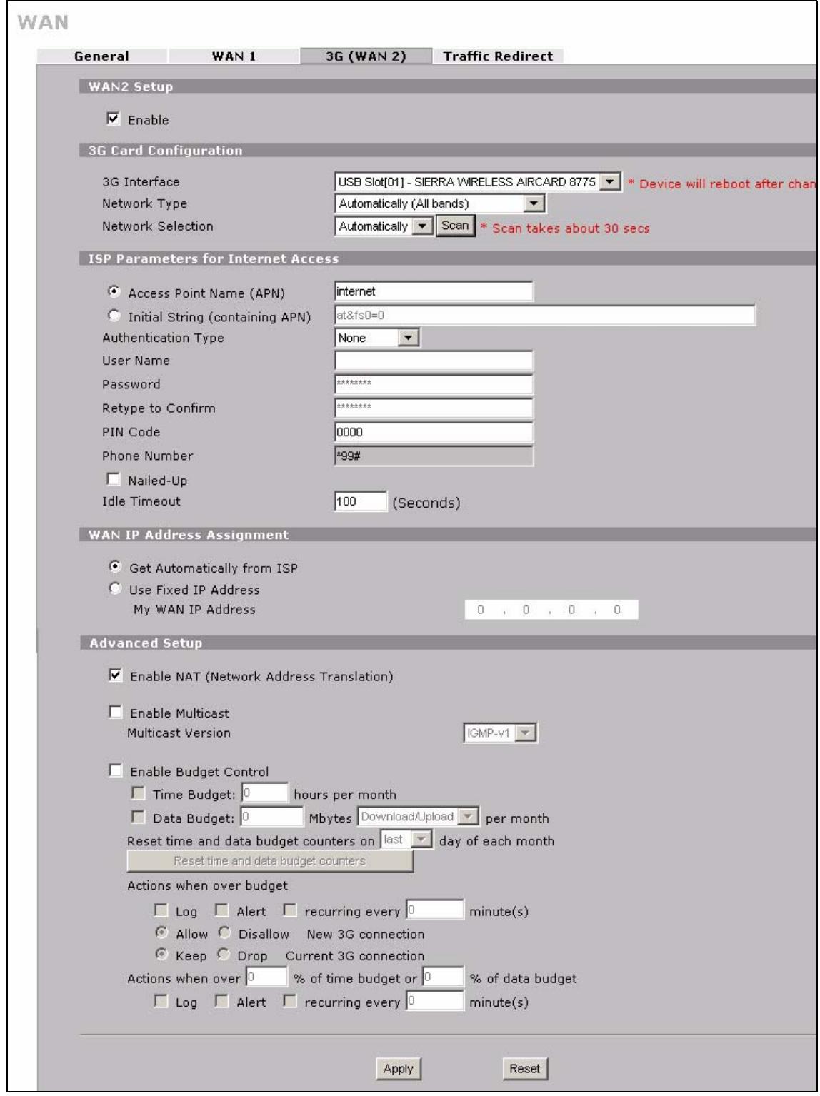
Figure 75 NETWORK > WAN > 3G (WAN 2)
The following table describes the labels in this screen.
Table 22 NETWORK > WAN > 3G (WAN 2)
| LABEL | DESCRIPTION |
| WAN2 Setup | |
| Enable | Select this option to enable WAN 2. The Network Type and Network Selection fields appear. |
| 3G Card Configuration | |
| 3G Interface | This displays the model of the 3G card installed in your ZyXEL Device. This may be installed internally or on the device's USB port. |
| Network Type | Select the type of 3G service and frequency band for your 3G connection. If you are unsure what to select, check with your 3G service provider to find the 3G service available to you in your region. Select Automatically (All bands) to have the card connect to the highest speed network available. Once connected the ZyXEL Device will continue searching for and connecting to the highest speed network as it becomes available. Select UMTS/HSDPA only (WCDMA 2100) to access HSDPA or UMTS networks available at 2100 Mhz in your region. At the time of writing, Europe and Asia offer UMTS or HSDPA using WCDMA 2100. Select GPRS/EDGE (GSM 900/1800) only to access GPRS or EDGE networks available at 900 or 1800 Mhz in your region. At the time of writing, Europe and most of Asia offer GPRS or EDGE using GSM 900/1800. GSM 1800 may also be known as DCS in some countries. Select GSM all to access GPRS or EDGE networks in other GSM frequency bands in other regions. Select WCDMA all to access UMTS or HSDPA networks in other WCDMA frequency bands in other regions. See Table 21 on page 127 for more information. |
| Network Selection | Select a 3G service provider for your connection. Otherwise, select Automatically to have the ZyXEL Device use the default settings on the 3G SIM card and connect to your service provider's base station. This shows Automatically by default. Click Scan to have the ZyXEL Device search for and display the available service providers. Ensure you have disconnected your 3G connection as the ZyXEL Device cannot scan for available 3G service providers while it has a 3G connection. This field resets to the default setting (Automatically) if the ZyXEL Device restarts. |
| ISP Parameters for Internet Access | |
| Access Point Name (APN) | Select this option and enter the APN (Access Point Name) if your ISP gives you the APN only. Connections with different APNs may provide different services (such as Internet access or MMS (Multi-Media Messaging Service)) and charge methods. You can enter up to 31 ASCII printable characters. Spaces are allowed. |
| Initial String (containing APN) | Select this option and enter the initial string and APN if you know how to configure or your ISP provides a string, which would include the APN, to initialize the 3G card. You can enter up to 72 ASCII printable characters. Spaces are allowed. |
| Authentication Type | The ZyXEL Device supports PAP (Password Authentication Protocol) and CHAP (Challenge Handshake Authentication Protocol). CHAP is more secure than PAP; however, PAP is readily available on more platforms.Use the drop-down list box to select an authentication protocol for outgoing calls. Options are:CHAP/PAP - Your ZyXEL Device accepts either CHAP or PAP when requested by the ISP.CHAP - Your ZyXEL Device accepts CHAP only.PAP - Your ZyXEL Device accepts PAP only.None - Your ZyXEL Device does not send your user name and password for authentication. The user name and password fields are grayed out. Select this option if your ISP did not give you a user name and password. |
| UserID | Type the user name (of up to 31 ASCII printable characters) given to you by your service provider. |
| Password | Type the password (of up to 31 ASCII printable characters) associated with the user name above. |
| Retype to Confirm | Type your password again to make sure that you have entered is correctly. |
| PIN Code | A PIN (Personal Identification Number) code is a key to a 3G card. Without the PIN code, you cannot use the 3G card.Enter the PIN code (four to eight digits, 0000 for example) provided by your ISP. If you enter the PIN code incorrectly, the 3G card may be blocked by your ISP and you cannot use the account to access the Internet.If your ISP disabled PIN code authentication, enter an arbitrary number.This field is available only when you insert a GSM 3G card.Check the HOME screen to see if you have entered the correct PIN. |
| Phone Number | Enter the phone number (dial string) used to dial up a connection to your service provider's base station. Your ISP should provide the dial string.By default, *99# is the dial string for GSM-based networks and #777 is the dial string for CDMA-based networks. |
| Nailed-Up | Select Nailed-Up if you do not want the connection to time out. |
| Idle Timeout | This specifies the time (from 0 to 9999) in seconds that elapses before the ZyXEL Device automatically disconnects from the ISP. |
| WAN IP Address Assignment | |
| Get automatically from ISP | Select this option if your ISP did not assign you a fixed IP address. This is the default selection. |
| Use Fixed IP Address | Select this option if the ISP assigned a fixed IP address. |
| My WAN IP Address | Enter your WAN IP address in this field if you selected Use Fixed IP Address. |
| Advanced Setup | |
| Enable NAT (Network Address Translation) | Network Address Translation (NAT) allows the translation of an Internet protocol address used within one network (for example a private IP address used in a local network) to a different IP address known within another network (for example a public IP address used on the Internet).Select this checkbox to enable NAT.For more information about NAT see Chapter 12 on page 225. |
| Enable Multicast | Select this check box to turn on IGMP (Internet Group Multicast Protocol). IGMP is a network-layer protocol used to establish membership in a Multicast group - it is not used to carry user data. |
| Multicast Version | Choose None (default), IGMP-V1 or IGMP-V2. IGMP (Internet Group Multicast Protocol) is a session-layer protocol used to establish membership in a Multicast group - it is not used to carry user data. IGMP version 2 (RFC 2236) is an improvement over version 1 (RFC 1112) but IGMP version 1 is still in wide use. If you would like to read more detailed information about interoperability between IGMP version 2 and version 1, please see sections 4 and 5 of RFC 2236. |
| Enable Budget Control | Select this check box to set a monthly limit for the user account of the installed 3G card. You must insert a 3G card before you enable budget control on the ZyXEL Device. You can set a limit on the total traffic and/or call time. The ZyXEL Device takes the actions you specified when a limit is exceeded during the month. |
| Time Budget | Select this check box and specify the amount of time (in hours) that the 3G connection can be used within one month. If you change the value after you configure and enable budget control, the ZyXEL Device resets the statistics. |
| Data Budget | Select this check box and specify how much downstream and/or upstream data (in Mbytes) can be transmitted via the 3G connection within one month. Select Download to set a limit on the downstream traffic (from the ISP to the ZyXEL Device). Select Upload to set a limit on the upstream traffic (from the ZyXEL Device to the ISP). Select Download/Upload to set a limit on the total traffic in both directions. If you change the value after you configure and enable budget control, the ZyXEL Device resets the statistics. |
| Reset time and data budget counters on | Select the date on which the ZyXEL Device resets the budget every month. If the date you selected is not available in a month, such as 30th or 31th, the ZyXEL Device resets the budget on the last day of the month. |
| Reset time and data budget counters | This button is available only when you enable budget control in this screen. Click this button to reset the time and data budgets immediately. The count starts over with the 3G connection's full configured monthly time and data budgets. This does not affect the normal monthly budget restart. |
| Actions when over budget | Specify the actions the ZyXEL Device takes when the time or data limit is exceeded. Select Log to create a log. Select Alert to create an alert. This option is available only when you select Log. If you select Log, you can also select recurring every to have the ZyXEL Device send a log (and alert if selected) for this event periodically. Specify how often (from 1 to 65535 minutes) to send the log (and alert if selected). Select Allow to permit new 3G connections or Disallow to drop/block new 3G connections. Select Keep to maintain the existing 3G connection or Drop to disconnect it. You cannot select Allow and Drop at the same time. If you select Disallow and Keep, the ZyXEL Device allows you to transmit data using the current connection, but you cannot build a new connection if the existing connection is disconnected. |
| Actions when over % of time budget or % of data budget | Specify the actions the ZyXEL Device takes when the specified percentage of time budget or data limit is exceeded. Enter a number from 1 to 99 in the percentage fields. If you change the value after you configure and enable budget control, the ZyXEL Device resets the statistics. Select Log to create a log. Select Alert to create an alert. This option is available only when you select Log. If you select Log, you can also select recurring every to have the ZyXEL Device send a log (and alert if selected) for this event periodically. Specify how often (from 1 to 65535 minutes) to send the log (and alert if selected). |
| Apply | Click Apply to save your changes. |
| Reset | Click Reset to begin configuring this screen afresh. |
6.10 Traffic Redirect
Traffic redirect forwards WAN traffic to a backup gateway when the ZyXEL Device cannot connect to the Internet through its normal gateway. Connect the backup gateway on the WAN so that the ZyXEL Device still provides firewall protection for the LAN.
Figure 76 Traffic Redirect WAN Setup
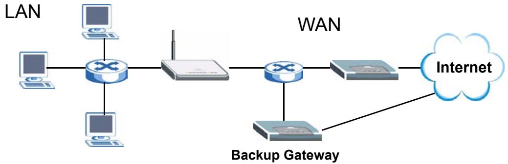
Figure 77 Traffic Redirect LAN Setup
IP alias allows you to avoid triangle route security issues when the backup gateway is connected to the LAN or DMZ. Use IP alias to configure the LAN into two or three logical networks with the ZyXEL Device itself as the gateway for each LAN network. Put the protected LAN in one subnet (Subnet 1 in the following figure) and the backup gateway in another subnet (Subnet 2). Configure a LAN to LAN/ZyXEL Device firewall rule that forwards packets from the protected LAN (Subnet 1) to the backup gateway (Subnet 2).
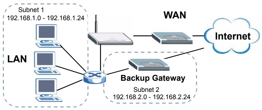
6.11 Configuring Traffic Redirect
To change your ZyXEL Device's traffic redirect settings, click NETWORK > WAN > Traffic Redirect. The screen appears as shown.
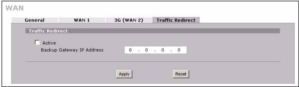
Figure 78 NETWORK > WAN > Traffic Redirect
The following table describes the labels in this screen.
Table 23 NETWORK > WAN > Traffic Redirect
| LABEL | DESCRIPTION |
| Active | Select this check box to have the ZyXEL Device use traffic redirect if the normal WAN connection goes down. |
| Backup Gateway IP Address | Type the IP address of your backup gateway in dotted decimal notation. The ZyXEL Device automatically forwards traffic to this IP address if the ZyXEL Device's Internet connection terminates. |
| Apply | Click Apply to save your changes. |
| Reset | Click Reset to begin configuring this screen afresh. |
DMZ Screens
This chapter describes how to configure the ZyXEL Device's DMZ.
7.1 DMZ
The DeMilitarized Zone (DMZ) provides a way for public servers (Web, e-mail, FTP, etc.) to be visible to the outside world (while still being protected from DoS (Denial of Service) attacks such as SYN flooding and Ping of Death). These public servers can also still be accessed from the secure LAN.
By default the firewall allows traffic between the WAN and the DMZ, traffic from the DMZ to the LAN is denied, and traffic from the LAN to the DMZ is allowed. Internet users can have access to host servers on the DMZ but no access to the LAN, unless special filter rules allowing access were configured by the administrator or the user is an authorized remote user.
It is highly recommended that you connect all of your public servers to the DMZ port(s).
It is also highly recommended that you keep all sensitive information off of the public servers connected to the DMZ port. Store sensitive information on LAN computers.
7.2 Configuring DMZ
The DMZ and the connected computers can have private or public IP addresses.
When the DMZ uses public IP addresses, the WAN and DMZ ports must use public IP addresses that are on separate subnets. See Appendix C on page 377 for information on IP subnetting. If you do not configure SUA NAT or any full feature NAT mapping rules for the public IP addresses on the DMZ, the ZyXEL Device will route traffic to the public IP addresses on the DMZ without performing NAT. This may be useful for hosting servers for NAT unfriendly applications (see Chapter 12 on page 225 for more information).
If the DMZ computers use private IP addresses, use NAT if you want to make them publicly accessible.
Like the LAN, the ZyXEL Device can also assign TCP/IP configuration via DHCP to computers connected to the DMZ ports.
From the main menu, click NETWORK > DMZ to open the DMZ screen. The screen appears as shown next.
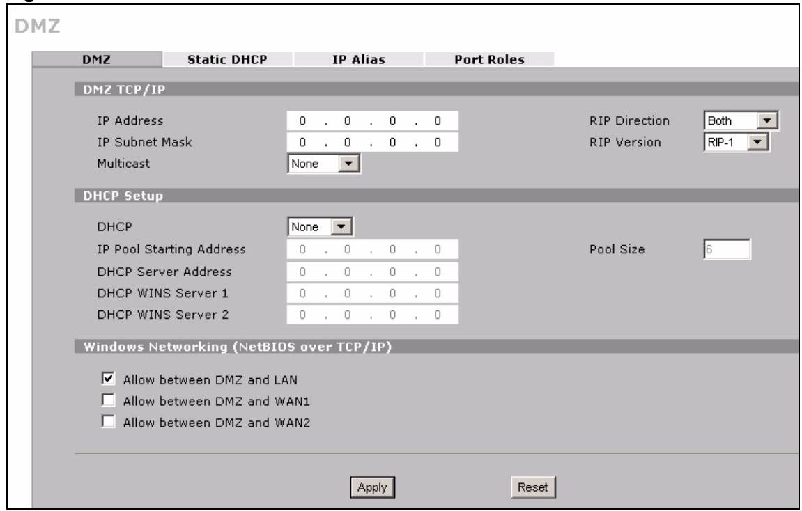
Figure 79 NETWORK > DMZ
The following table describes the labels in this screen.
Table 24 NETWORK > DMZ
| LABEL | DESCRIPTION |
| DMZ TCP/IP | |
| IP Address | Type the IP address of your ZyXEL Device's DMZ port in dotted decimal notation.Note: Make sure the IP addresses of the LAN, WAN and DMZ are on separate subnets. |
| IP Subnet Mask | The subnet mask specifies the network number portion of an IP address. Your ZyXEL Device will automatically calculate the subnet mask based on the IP address that you assign. Unless you are implementing subnetting, use the subnet mask computed by the ZyXEL Device 255.255.255.0. |
| RIP Direction | RIP (Routing Information Protocol, RFC1058 and RFC 1389) allows a router to exchange routing information with other routers. The RIP Direction field controls the sending and receiving of RIP packets. Select the RIP direction from Both/In Only/Out Only/None. When set to Both or Out Only, the ZyXEL Device will broadcast its routing table periodically. When set to Both or In Only, it will incorporate the RIP information that it receives; when set to None, it will not send any RIP packets and will ignore any RIP packets received. Both is the default. |
| RIP Version | The RIP Version field controls the format and the broadcasting method of the RIP packets that the ZyXEL Device sends (it recognizes both formats when receiving). RIP-1 is universally supported but RIP-2 carries more information. RIP-1 is probably adequate for most networks, unless you have an unusual network topology. Both RIP-2B and RIP-2M sends the routing data in RIP-2 format; the difference being that RIP-2B uses subnet broadcasting while RIP-2M uses multicasting. Multicast can reduce the load on non-router machines since they generally do not listen to the RIP multicast address and so will not receive the RIP packets. However, if one router uses multicast, then all routers on your network must use multicasting, also. By default, RIP direction is set to Both and the Version set to RIP-1. |
| Multicast | Select IGMP V-1 or IGMP V-2 or None. IGMP (Internet Group Multicast Protocol) is a network-layer protocol used to establish membership in a Multicast group - it is not used to carry user data. IGMP version 2 (RFC 2236) is an improvement over version 1 (RFC 1112) but IGMP version 1 is still in wide use. If you would like to read more detailed information about interoperability between IGMP version 2 and version 1, please see sections 4 and 5 of RFC 2236. |
| DHCP Setup | |
| DHCP | DHCP (Dynamic Host Configuration Protocol, RFC 2131 and RFC 2132) allows individual clients (workstations) to obtain TCP/IP configuration at startup from a server. Unless you are instructed by your ISP, leave this field set to Server. When configured as a server, the ZyXEL Device provides TCP/IP configuration for the clients. When set as a server, fill in the IP Pool Starting Address and Pool Size fields. Select Relay to have the ZyXEL Device forward DHCP requests to another DHCP server. When set to Relay, fill in the DHCP Server Address field. Select None to stop the ZyXEL Device from acting as a DHCP server. When you select None, you must have another DHCP server on your LAN, or else the computers must be manually configured. |
| IP Pool Starting Address | This field specifies the first of the contiguous addresses in the IP address pool. |
| Pool Size | This field specifies the size, or count of the IP address pool. |
| DHCP Server Address | Type the IP address of the DHCP server to which you want the ZyXEL Device to relay DHCP requests. Use dotted decimal notation. Alternatively, click the right mouse button to copy and/or paste the IP address. |
| DHCP WINS Server 1, 2 | Type the IP address of the WINS (Windows Internet Naming Service) server that you want to send to the DHCP clients. The WINS server keeps a mapping table of the computer names on your network and the IP addresses that they are currently using. |
| Windows Networking (NetBIOS over TCP/IP) | |
| Allow between DMZ and LAN | Select this check box to forward NetBIOS packets from the LAN to the DMZ and from the DMZ to the LAN. If your firewall is enabled with the default policy set to block DMZ to LAN traffic, you also need to configure a DMZ to LAN firewall rule that forwards NetBIOS traffic. Clear this check box to block all NetBIOS packets going from the LAN to the DMZ and from the DMZ to the LAN. |
| Allow between DMZ and WAN 1 | Select this check box to forward NetBIOS packets from the DMZ to WAN 1 and from WAN 1 to the DMZ. Clear this check box to block all NetBIOS packets going from the DMZ to WAN 1 and from WAN 1 to the DMZ. |
| Allow between DMZ and WAN 2 | Select this check box to forward NetBIOS packets from the DMZ to WAN 2 and from WAN 2 to the DMZ. Clear this check box to block all NetBIOS packets going from the DMZ to WAN 2 and from WAN 2 to the DMZ. |
| Apply | Click Apply to save your changes. |
| Reset | Click Reset to begin configuring this screen afresh. |
7.3 DMZ Static DHCP
This table allows you to assign IP addresses on the DMZ to specific individual computers based on their MAC Addresses.
Every Ethernet device has a unique MAC (Media Access Control) address. The MAC address is assigned at the factory and consists of six pairs of hexadecimal characters, for example, 00:A0:C5:00:00:02.
To change your ZyXEL Device's static DHCP settings on the DMZ, click NETWORK > DMZ > Static DHCP. The screen appears as shown.
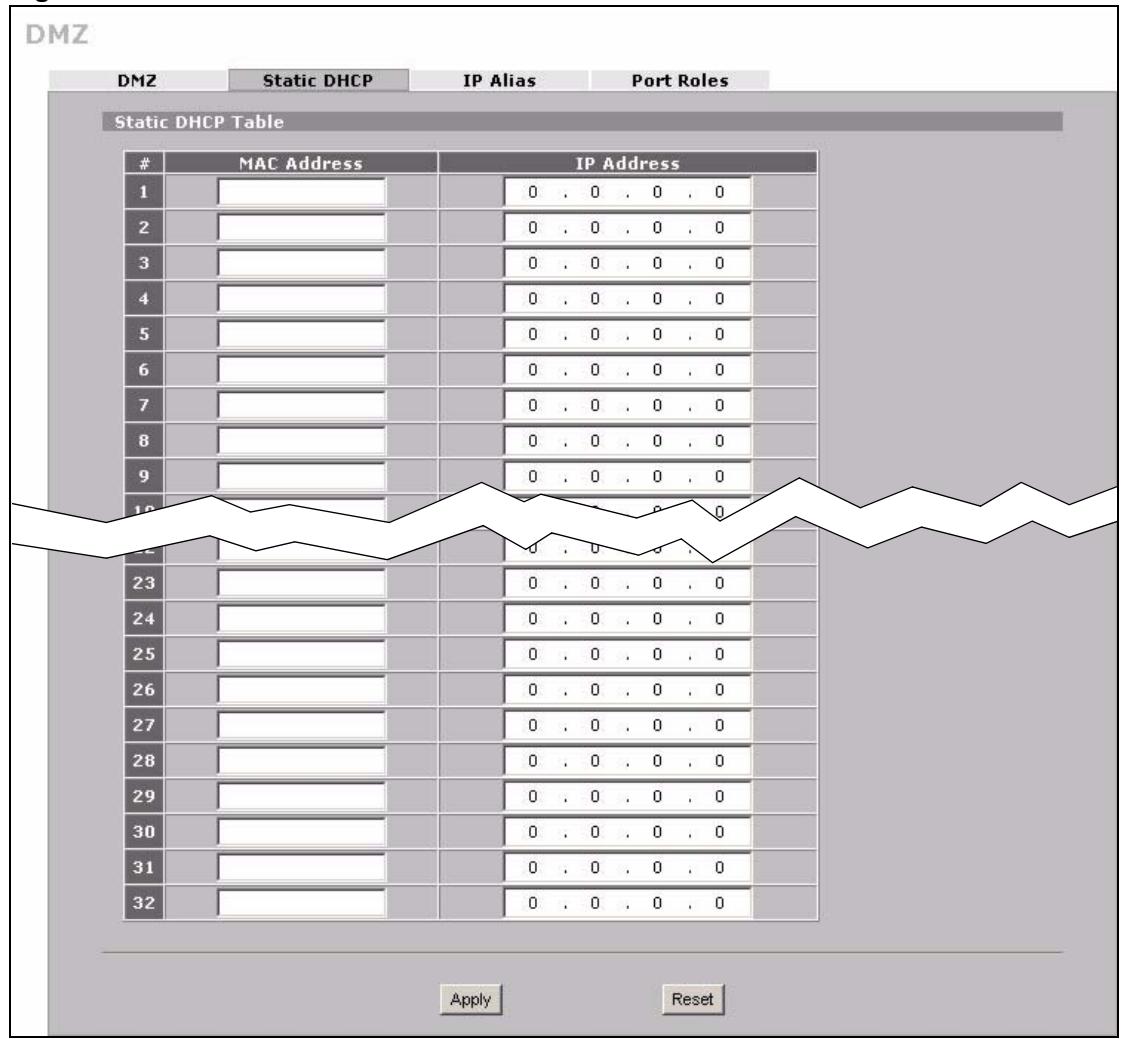
Figure 80 NETWORK > DMZ > Static DHCP
The following table describes the labels in this screen.
Table 25 NETWORK > DMZ > Static DHCP
| LABEL | DESCRIPTION |
| # | This is the index number of the Static IP table entry (row). |
| MAC Address | Type the MAC address of a computer on your DMZ. |
| IP Address | Type the IP address that you want to assign to the computer on your DMZ. Alternatively, click the right mouse button to copy and/or paste the IP address. |
Table 25 NETWORK > DMZ > Static DHCP
| LABEL | DESCRIPTION |
| Apply | Click Apply to save your changes. |
| Reset | Click Reset to begin configuring this screen afresh. |
7.4 DMZ IP Alias
IP alias allows you to partition a physical network into different logical networks over the same Ethernet interface.
The ZyXEL Device has a single DMZ interface. Even though more than one of ports 1 4 may be in the DMZ port role, they are all still part of a single physical Ethernet interface and all use the same IP address.
The ZyXEL Device supports three logical DMZ interfaces via its single physical DMZ Ethernet interface. The ZyXEL Device itself is the gateway for each of the logical DMZ networks.
The IP alias IP addresses can be either private or public regardless of whether the physical DMZ interface is set to use a private or public IP address. Use NAT if you want to make DMZ computers with private IP addresses publicly accessible (see Chapter 12 on page 225 for more information). When you use IP alias, you can have the DMZ use both public and private IP addresses at the same time.

Make sure that the subnets of the logical networks do not overlap.
To change your ZyXEL Device's IP alias settings, click NETWORK > DMZ > IP Alias. The screen appears as shown.
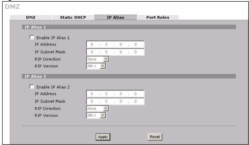
Figure 81 NETWORK > DMZ > IP Alias
The following table describes the labels in this screen.
Table 26 NETWORK > DMZ > IP Alias
| LABEL | DESCRIPTION |
| Enable IP Alias 1, 2 | Select the check box to configure another DMZ network for the ZyXEL Device. |
| IP Address | Enter the IP address of your ZyXEL Device in dotted decimal notation.Note: Make sure the IP addresses of the LAN, WAN and DMZ are on separate subnets. |
| IP Subnet Mask | Your ZyXEL Device will automatically calculate the subnet mask based on the IP address that you assign. Unless you are implementing subnetting, use the subnet mask computed by the ZyXEL Device. |
| RIP Direction | RIP (Routing Information Protocol, RFC1058 and RFC 1389) allows a router to exchange routing information with other routers. The RIP Direction field controls the sending and receiving of RIP packets. Select the RIP direction from Both/In Only/Out Only/None. When set to Both or Out Only, the ZyXEL Device will broadcast its routing table periodically. When set to Both or In Only, it will incorporate the RIP information that it receives; when set to None, it will not send any RIP packets and will ignore any RIP packets received. |
| RIP Version | The RIP Version field controls the format and the broadcasting method of the RIP packets that the ZyXEL Device sends (it recognizes both formats when receiving). RIP-1 is universally supported but RIP-2 carries more information. RIP-1 is probably adequate for most networks, unless you have an unusual network topology. Both RIP-2B and RIP-2M sends the routing data in RIP-2 format; the difference being that RIP-2B uses subnet broadcasting while RIP-2M uses multicasting. Multicasting can reduce the load on non-router machines since they generally do not listen to the RIP multicast address and so will not receive the RIP packets. However, if one router uses multicastasting, then all routers on your network must use multicastasting, also. By default, RIP direction is set to Both and the Version set to RIP-1. |
| Apply | Click Apply to save your changes. |
| Reset | Click Reset to begin configuring this screen afresh. |
7.5 DMZ Public IP Address Example
The following figure shows a simple network setup with public IP addresses on the WAN and DMZ and private IP addresses on the LAN. Lower case letters represent public IP addresses (like a.b.c.d for example). The LAN port and connected computers (A through C) use private IP addresses that are in one subnet. The DMZ port and connected servers (D through F) use public IP addresses that are in another subnet. The public IP addresses of the DMZ and WAN ports are in separate subnets.
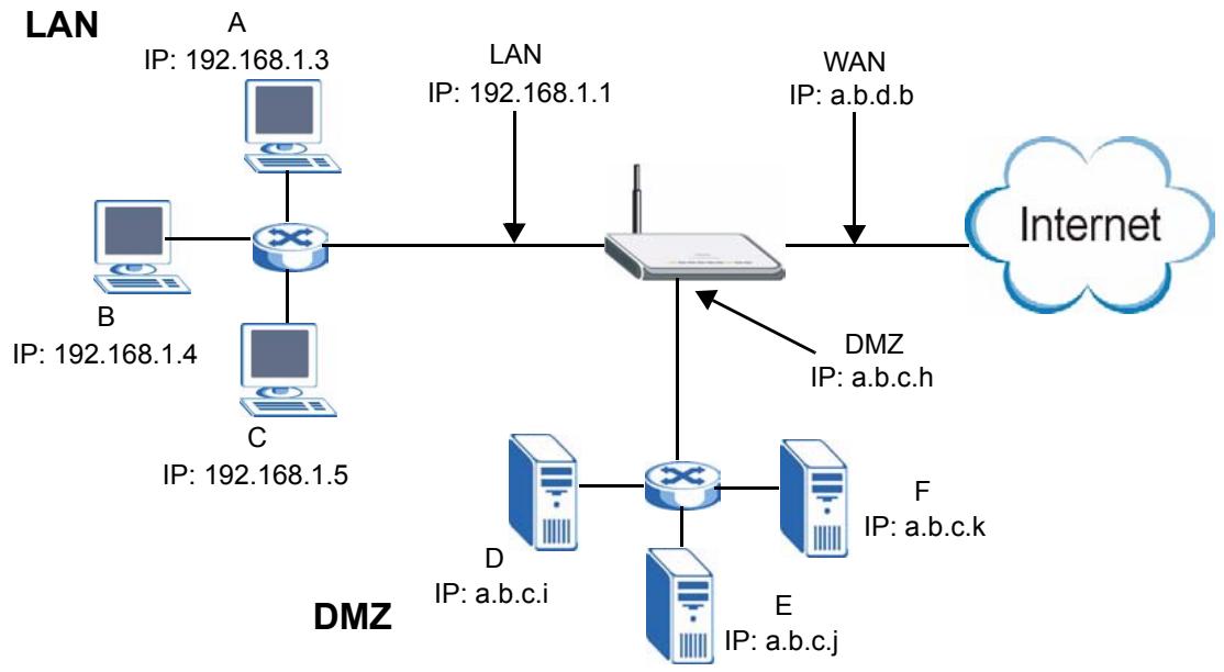
Figure 82 DMZ Public Address Example
7.6 DMZ Private and Public IP Address Example
The following figure shows a network setup with both private and public IP addresses on the DMZ. Lower case letters represent public IP addresses (like a.b.c.d for example). The LAN port and connected computers (A through C) use private IP addresses that are in one subnet. The DMZ port and server F use private IP addresses that are in one subnet. The private IP addresses of the LAN and DMZ are on separate subnets. The DMZ port and connected servers (D and E) use public IP addresses that are in one subnet. The public IP addresses of the DMZ and WAN are on separate subnets.
Configure one subnet (either the public or the private) in the Network > DMZ screen (see Figure 7.2 on page 135) and configure the other subnet in the Network > DMZ > IP Alias screen (see Figure 7.4 on page 139) to use this kind of network setup. You also need to configure NAT for the private DMZ IP addresses.
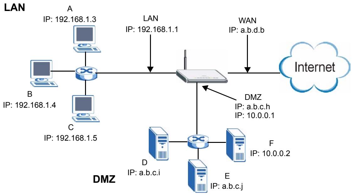
Figure 83 DMZ Private and Public Address Example
7.7 DMZ Port Roles
Use the Port Roles screen to set ports as part of the LAN and/or DMZ interface.
Ports 1~4 on the ZyXEL Device can be part of the LAN and/or DMZ interface.

Do the following if you are configuring from a computer connected to a LAN or DMZ port and changing the port's role:
1 A port's IP address varies as its role changes, make sure your computer's IP address is in the same subnet as the ZyXEL Device's LAN or DMZ IP address.
2 Use the appropriate LAN or DMZ IP address to access the ZyXEL Device.
To change your ZyXEL Device's port role settings, click NETWORK > DMZ > Port Roles. The screen appears as shown.
The radio buttons correspond to Ethernet ports on the front panel of the ZyXEL Device. On the ZyXEL Device, ports 1 to 4 are all LAN ports by default.

Your changes are also reflected in the LAN Port Roles screens.
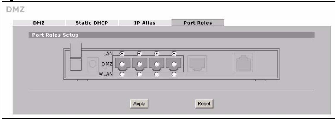
Figure 84 NETWORK > DMZ > Port Roles
The following table describes the labels in this screen.
Table 27 NETWORK > DMZ > Port Roles
| LABEL | DESCRIPTION |
| LAN | Select a port's LAN radio button to use the port as part of the LAN. The port will use the ZyXEL Device's LAN IP address and MAC address. |
| DMZ | Select a port's DMZ radio button to use the port as part of the DMZ. The port will use the ZyXEL Device's DMZ IP address and MAC address. |
| Apply | Click Apply to save your changes. |
| Reset | Click Reset to begin configuring this screen afresh. |
PART III
Wireless
Wi-Fi (147)
This chapter discusses how to configure wireless LAN on the ZyXEL Device.
8.1 Wi-Fi Introduction
Your ZyXEL Device comes with an internal Wi-Fi card, providing AP (access point) functionality, and allowing you to set up a wireless LAN (WLAN). Before you set up your WLAN it is important to understand WLAN and WLAN security concepts.
A wireless LAN can be as simple as two computers with wireless LAN adapters communicating in a peer-to-peer network or as complex as a number of computers with wireless LAN adapters communicating through access points which bridge network traffic to the wired LAN.
The following figure provides an example of a wireless network.
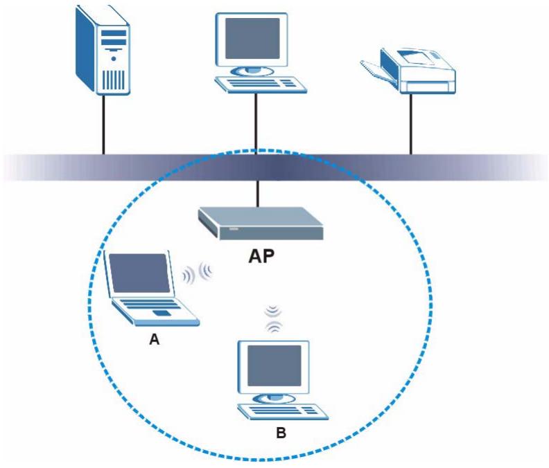
Figure 85 Example of a Wireless Network
The wireless network is the part in the blue circle. In this wireless network, devices A and B are called wireless clients. The wireless clients use the access point (AP) to interact with other devices (such as the printer) or with the Internet. Your ZyXEL Device is the AP.
Every wireless network must follow these basic guidelines.
- Every wireless client in the same wireless network must use the same SSID.
The SSID is the name of the wireless network. It stands for Service Set IDentity.
- If two wireless networks overlap, they should use different channels.
Like radio stations or television channels, each wireless network uses a specific channel, or frequency, to send and receive information.
- Every wireless client in the same wireless network must use security compatible with the AP.
Security stops unauthorized devices from using the wireless network. It can also protect the information that is sent in the wireless network.

See the WLAN appendix for more detailed information on WLANs.
8.2 Wireless Security Overview
The following sections introduce different types of wireless security you can set up in the wireless network.
8.2.1 SSD
Normally, the AP acts like a beacon and regularly broadcasts the SSID in the area. You can hide the SSID instead, in which case the AP does not broadcast the SSID. In addition, you should change the default SSID to something that is difficult to guess.
This type of security is fairly weak, however, because there are ways for unauthorized devices to get the SSID. In addition, unauthorized devices can still see the information that is sent in the wireless network.
8.2.2 MAC Address Filter
Every wireless client has a unique identification number, called a MAC address. A MAC address is usually written using twelve hexadecimal characters; for example, 00A0C5000002 or 00:A0:C5:00:00:02. To get the MAC address for each wireless client, see the appropriate User's Guide or other documentation.
- Some wireless devices, such as scanners, can detect wireless networks but cannot use wireless networks. These kinds of wireless devices might not have MAC addresses.
- Hexadecimal characters are 0, 1, 2, 3, 4, 5, 6, 7, 8, 9, A, B, C, D, E, and F.
You can use the MAC address filter to tell the AP which wireless clients are allowed or not allowed to use the wireless network. If a wireless client is allowed to use the wireless network, it still has to have the correct settings (SSID, channel, and security). If a wireless client is not allowed to use the wireless network, it does not matter if it has the correct settings.
This type of security does not protect the information that is sent in the wireless network. Furthermore, there are ways for unauthorized devices to get the MAC address of an authorized wireless client. Then, they can use that MAC address to use the wireless network.
8.2.3 User Authentication
You can make every user log in to the wireless network before they can use it. This is called user authentication. However, every wireless client in the wireless network has to support IEEE 802.1x to do this.
For wireless networks, there are two typical places to store the user names and passwords for each user.
- In the AP: this feature is called a local user database or a local database.
- In a RADIUS server: this is a server used in businesses more than in homes.
If your AP does not provide a local user database and if you do not have a RADIUS server, you cannot set up user names and passwords for your users.
Unauthorized devices can still see the information that is sent in the wireless network, even if they cannot use the wireless network. Furthermore, there are ways for unauthorized wireless users to get a valid user name and password. Then, they can use that user name and password to use the wireless network.
Local user databases also have an additional limitation that is explained in the next section.
8.2.4 Encryption
Wireless networks can use encryption to protect the information that is sent in the wireless network. Encryption is like a secret code. If you do not know the secret code, you cannot understand the message.
The types of encryption you can choose depend on the type of user authentication. (See Section 8.2.3 on page 149 for information about this.)
Table 28 Types of Encryption for Each Type of Authentication
| Weakest Strongest | No Authentication | RADIUS Server |
| No Security | ||
| Static WEP | ||
| 802.1x +Static WEP | ||
| WPA-PSK | WPA | |
| WPA2-PSK or WPA2-PSK-Mix | WPA2 or WPA2-Mix |
For example, if the wireless network has a RADIUS server, you can choose WPA or WPA2. If users do not log in to the wireless network, you can choose no encryption, Static WEP, WPA-PSK, or WPA2-PSK.
Usually, you should set up the strongest encryption that every wireless client in the wireless network supports. For example, suppose the AP does not have a local user database, and you do not have a RADIUS server. Therefore, there is no user authentication. Suppose the wireless network has two wireless clients. Device A only supports WEP, and device B supports WEP and WPA. Therefore, you should set up Static WEP in the wireless network.

It is recommended that wireless clients use WPA-PSK, WPA, or stronger encryption. IEEE 802.1x and WEP encryption are better than none at all, but it is still possible for unauthorized devices to figure out the original information pretty quickly.

It is not possible to use WPA-PSK, WPA or stronger encryption with a local user database. In this case, it is better to set up stronger encryption with no authentication than to set up weaker encryption with the local user database.
If some wireless clients support WPA and some support WPA2, you should set up WPA2-PSK-Mix or WPA2-Mix (depending on the type of wireless network login) in the ZyXEL Device.
Many types of encryption use a key to protect the information in the wireless network. The longer the key, the stronger the encryption. Every wireless client in the wireless network must have the same key.
8.2.5 Additional Installation Requirements for Using 802.1x
- A computer with an IEEE 802.11b/g wireless LAN card.
- A computer equipped with a web browser (with JavaScript enabled) and/or Telnet.
- A wireless station must be running IEEE 802.1x-compliant software. Currently, this is offered in Windows XP.
- An optional network RADIUS server for remote user authentication and accounting.
8.3 Wireless Card
If you are configuring the ZyXEL Device from a computer connected to the wireless LAN and you change the ZyXEL Device's SSID or security settings, you will lose your wireless connection when you press Apply to confirm. You must then change the wireless settings of your computer to match the ZyXEL Device's new settings.
Click WILESS > Wi-Fi to open the Wireless Card screen.
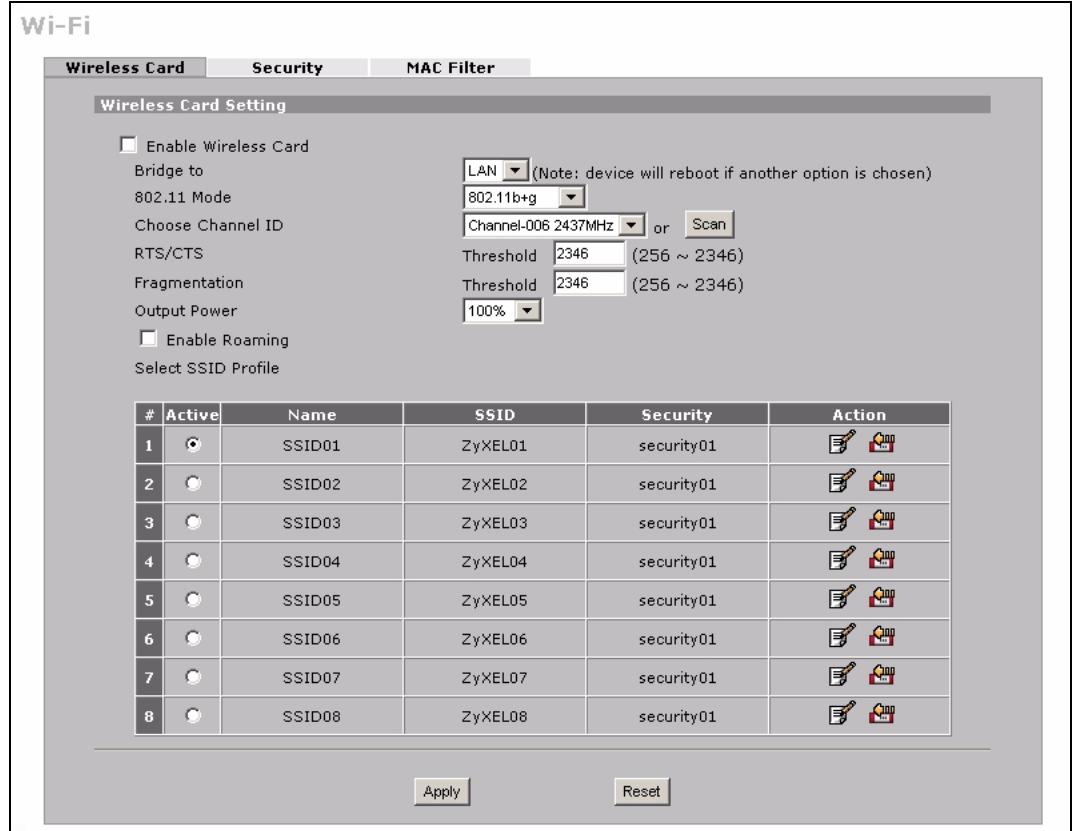
Figure 86 WIRELESS > Wi-Fi > Wireless Card
The following table describes the labels in this screen.
Table 29 WIRELESS > Wi-Fi > Wireless Card
| LABEL | DESCRIPTION |
| Enable Wireless Card | The wireless LAN through a wireless LAN card is turned off by default. Before you enable the wireless LAN you should configure security by setting MAC filters and/or 802.1x security; otherwise your wireless LAN will be vulnerable upon enabling it. Select the check box to enable the wireless LAN. |
| Bridge to | Select LAN to use the wireless card as part of the LAN. Select DMZ to use the wireless card as part of the DMZ. The ZyXEL Device restarts after you change the wireless card setting. Note: If you set the wireless card to be part of the LAN or DMZ, you can still use wireless access. The firewall will treat the wireless card as part of the LAN or DMZ respectively. |
| 802.11 Mode | Select 802.11b Only to allow only IEEE 802.11b compliant wireless devices to associate with the ZyXEL Device. Select 802.11g Only to allow only IEEE 802.11g compliant wireless devices to associate with the ZyXEL Device. Select 802.11b+g to allow both IEEE802.11b and IEEE802.11g compliant wireless devices to associate with the ZyXEL Device. The transmission rate of your ZyXEL Device might be reduced. |
| Choose Channel ID | Set the operating frequency/channel depending on your particular region. To manually set the ZyXEL Device to use a channel, select a channel from the drop-down list box. To have the ZyXEL Device automatically select a channel, click Scan instead. |
| Scan | Click this button to have the ZyXEL Device automatically select the wireless channel with the lowest interference. |
| RTS/CTS Threshold | In a wireless network which covers a large area, wireless devices are sometimes not aware of each other's presence. This may cause them to send information to the AP at the same time and result in information colliding and not getting through. RTS/CTS is designed to prevent collisions due to hidden nodes. You should only configure RTS/CTS if the possibility of hidden nodes exists on your network and the "cost" of resending large frames is more than the extra network overhead involved in the RTS (Request To Send)/CTS (Clear to Send) handshake. Enter a value between 256 and 2346. Data with a frame size larger than this value will perform the RTS (Request To Send)/CTS (Clear to Send) handshake. The lower the value, the more often the devices must get permission. If the RTS/CTS value is greater than the Fragmentation value, then the RTS/CTS handshake will never occur as data frames will be fragmented before they reach RTS/CTS size. |
| Fragmentation Threshold | This is the threshold (number of bytes) for the fragmentation boundary for directed messages. It is the maximum data fragment size that can be sent. Enter a value between 256 and 2346. |
| Output Power | Set the output power of the ZyXEL Device in this field. If there is a high density of APs in an area, decrease the output power to reduce interference with other APs. Select one of the following 100% (full power), 50%, 25%, 12.5% or min (minimum). See the product specifications for more information on your ZyXEL Device's output power. |
| Enable Roaming | Roaming allows wireless stations to switch from one access point to another as they move from one coverage area to another. Select this checkbox to enable roaming on the ZyXEL Device if you have two or more ZyXEL Devices on the same subnet. Note: All APs on the same subnet and the wireless clients must have the same SSID to allow roaming. |
| Select SSID Profile | An SSID profile is the set of parameters relating to one of the ZyXEL Device's BSSs. The SSID (Service Set IDentifier) identifies the Service Set with which a wireless client is associated. Wireless clients associating with the access point (AP) must have the same SSID.Note: If you are configuring the ZyXEL Device from a computer connected to the wireless LAN and you change the ZyXEL Device's SSID or security settings, you will lose your wireless connection when you press Apply to confirm. You must then change the wireless settings of your computer to match the ZyXEL Device's new settings. |
| # | This field displays the index number of each SSID profile. |
| Active | Choose a profile to apply to your wireless network by selecting its radio button. |
| Name | This field displays the identification name of each SSID profile on the ZyXEL Device. |
| SSID | This field displays the name of the wireless profile on the network. When a wireless client scans for an AP to associate with, this is the name that is broadcast and seen in the wireless client utility. |
| Security | This field indicates which security profile is currently associated with each SSID profile.See Section 8.4 on page 154 for more information. |
| Action | Click the edit icon next to the profile you want to configure and go to the SSID configuration screen.Click the reset default icon to clear all user-entered configuration information and return the SSID profile to its factory defaults. |
| Apply | Click Apply to save your changes. |
| Reset | Click Reset to begin configuring this screen afresh. |
8.3.1 SSD Profile
Configure wireless network security by configuring and applying an SSID profile. You can configure multiple profiles but you can only apply one to your network.
Use the Wireless Card screen to see information about the SSID profiles on the ZyXEL Device, and use the Wireless Card > Edit screen to configure the SSID profiles.
Each SSID profile references the settings configured in the following screens:
- WIRELESS > Wi-Fi> Security (one of the security profiles).
- AUTHSERVER > RADIUS (the RADIUS server settings).
- WIRELESS > Wi-Fi > MAC Filter (the MAC filter list, if activated in the SSID profile).
Configure the fields in the above screens to use the settings in an SSID profile.
In the Wireless Card screen, click the edit icon next to an SSID profile to display the following screen.
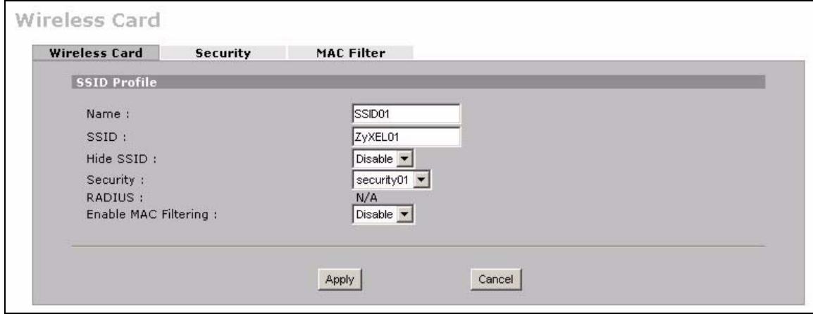
Figure 87 WIRELESS > Wi-Fi > Configuring SSID
The following table describes the labels in this screen.
Table 30 WIRELESS > Wi-Fi > Configuring SSID
| LABEL | DESCRIPTION |
| Name | Enter a name (up to 32 printable 7-bit ASCII characters) identifying this profile. |
| SSID | When a wireless client scans for an AP to associate with, this is the name that is broadcast and seen in the wireless client utility. Enter a descriptive name (up to 32 printable 7-bit ASCII characters) for the wireless LAN. |
| HideSSID | Select Disable if you want the ZyXEL Device to broadcast thisSSID (a wireless client scanning for an AP will find thisSSID). Alternatively, select Enable to have the ZyXEL Device hide thisSSID (a wireless client scanning for an AP will not find thisSSID). |
| Security | Select a security profile to use with thisSSID profile. See Section 8.4 on page 154 for more information. |
| RADIUS | This displays N/A if the security profile you selected does not use RADIUS authentication. See Section 8.4 on page 154 for more information. This displays Radius Configuration if you select a security profile that uses RADIUS authentication. Click Radius Configuration to go to the RADIUS screen where you can view and/or change the RADIUS settings. See Section 10.3 on page 193 for more information. |
| Enable MAC Filtering | Select Enable from the drop down list box to activate MAC address filtering. |
| Apply | Click Apply to save your customized settings and exit this screen. |
| Cancel | Click Cancel to exit this screen without saving. |
8.4 Configuring Wireless Security
Click WIRELESS > Wi-Fi > Security to open the Security screen. Use this screen to create security profiles. A security profile is a group of configuration settings which can be assigned to an SSID profile in the Wireless Card screen.
The screen changes when you configure a security profile and varies according to the security modes you select.
The following table describes the security modes you can configure.
Table 31 Security Modes
| SECURITY MODE | DESCRIPTION |
| None | Select this to have no data encryption. |
| WEP | Select this to use WEP encryption. |
| 802.1x-Only | Select this to use 802.1x authentication with no data encryption. |
| 802.1x-Static64 | Select this to use 802.1x authentication with a static 64bit WEP key and an authentication server. |
| 802.1x-Static128 | Select this to use 802.1x authentication with a static 128bit WEP key and an authentication server. |
| WPA | Select this to use WPA. |
| WPA-PSK | Select this to use WPA with a pre-shared key. |
| WPA2 | Select this to use WPA2. |
| WPA2-MIX | Select this to use either WPA2 or WPA depending on which security mode the wireless client uses. |
| WPA2-PSK | Select this to use WPA2 with a pre-shared key. |
| WPA2-PSK-MIX | Select this to use either WPA-PSK or WPA2-PSK depending on which security mode the wireless client uses. |
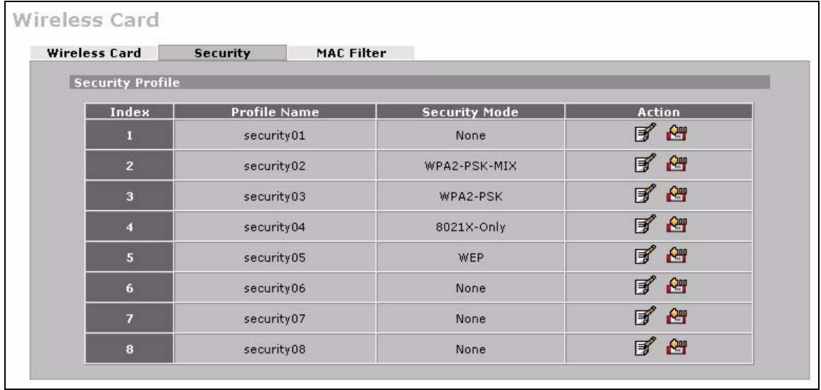
Figure 88 WIRELESS > Wi-Fi > Security
The following table describes the labels in this screen.
Table 32 WIRELESS > Wi-Fi > Security
| LABEL | DESCRIPTION |
| Security Profile | |
| Index | This is the index number of the security profile. |
| Profile Name | This field displays a name given to a security profile in the Security configuration screen. |
| Security Mode | This field displays the security mode this security profile uses. |
| Action | Click the edit icon to configure security settings for that profile. Click the reset default icon to clear all user-entered configuration information and return the security profile to its factory defaults. |
8.4.1 No Security

If you do not enable any wireless security on your ZyXEL Device, your network is accessible to any wireless networking device within range.
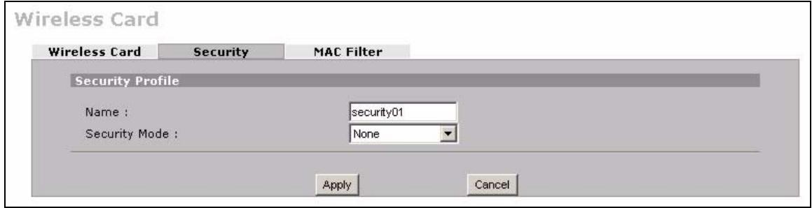
Figure 89 WIRELESS > Wi-Fi > Security: None
The following table describes the wireless LAN security labels in this screen.
Table 33 WIRELESS > Wi-Fi > Security: None
| LABEL | DESCRIPTION |
| Name | Type a name (up to 32 printable 7-bit ASCII characters) to identify this security profile. |
| Security Mode | Select None to allow wireless clients to communicate with the access points without any data encryption. |
| Apply | Click Apply to save your customized settings and exit this screen. |
| Cancel | Click Cancel to exit this screen without saving. |
8.4.2 Static WEP
Static WEP provides a mechanism for encrypting data using encryption keys. Both the AP and the wireless stations must use the same WEP key to encrypt and decrypt data.
Your ZyXEL Device allows you to configure up to four 64-bit, 128-bit or 152-bit WEP keys, but only one key can be used at any one time.
In order to configure and enable WEP encryption, click WILESS > Wi-Fi > Security > Edit.
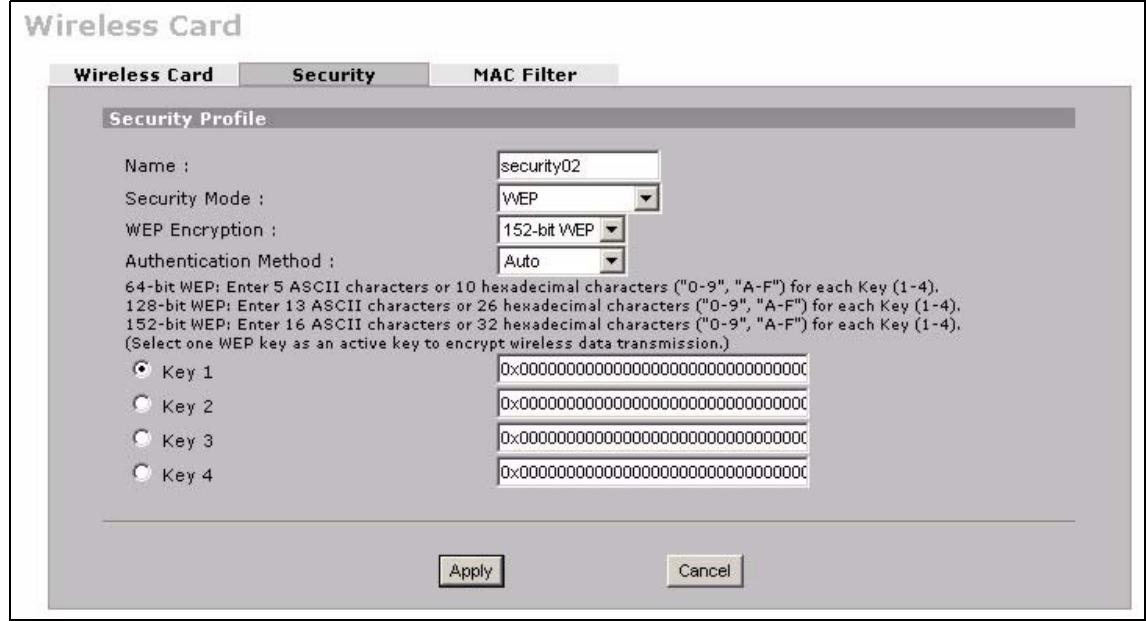
Figure 90 WIRELESS > Wi-Fi > Security: WEP
The following table describes the labels in this screen.
Table 34 WIRELESS > Wi-Fi > Security: WEP
| LABEL | DESCRIPTION |
| Name | Type a name to identify this security profile. |
| Security Mode | Select WEP from the drop-down list. |
| WEP Encryption | WEP (Wired Equivalent Privacy) provides data encryption to prevent unauthorized wireless stations from accessing data transmitted over the wireless network. Select 64-bit WEP, 128-bit WEP or 152-bit WEP to enable data encryption. |
| Authentication Method | Select Shared-Key to have the ZyXEL Device use the default WEP key to authenticate the wireless client to the ZyXEL Device. Select Auto to have the ZyXEL Device switch between the shared-key and open system (the wireless clients and AP do not share a secret key for authentication) modes automatically. The default setting is Auto. |
| Key 1 to Key 4 | The WEP keys are used to encrypt data. Both the ZyXEL Device and the wireless clients must use the same WEP key for data transmission. If you chose 64-bit WEP in the WEP Encryption field, then enter any 5 ASCII characters or 10 hexadecimal characters ("0-9", "A-F") preceded by 0x for each key. If you chose 128-bit WEP in the WEP Encryption field, then enter 13 ASCII characters or 26 hexadecimal characters ("0-9", "A-F") preceded by 0x for each key. If you chose 152-bit WEP in the WEP Encryption field, then enter 16 ASCII characters or 32 hexadecimal characters ("0-9", "A-F") preceded by 0x for each key. You can configure up to four keys, but only one key can be activated at any one time. The default key is key 1. |
| Apply | Click Apply to save your customized settings and exit this screen. |
| Cancel | Click Cancel to exit this screen without saving. |
8.4.3 IEEE 802.1x Only
Click the WIRELESS > Wi-Fi > Security > Edit. Select 8021X-Only from the Security Mode list.
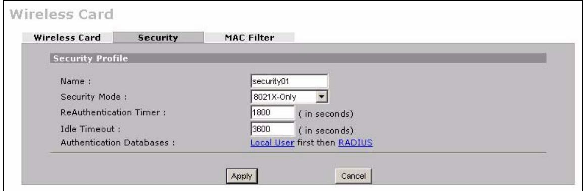
Figure 91 WIRELESS > Wi-Fi > Security: 802.1x Only
The following table describes the labels in this screen.
Table 35 WIRELESS > Wi-Fi > Security: 802.1x Only
| LABEL | DESCRIPTION |
| Name | Type a name to identify this security profile. |
| Security Mode | Select 8021X-Only from the drop-down list. |
| ReAuthentication Timer | Specify how often wireless clients have to resend user names and passwords in order to stay connected. Enter a time interval between 600 and 65535 seconds. If wireless client authentication is done using a RADIUS server, the reauthentication timer on the RADIUS server has priority. |
| Idle Timeout | The ZyXEL Device automatically disconnects a wireless client from the wireless network after a period of inactivity. The wireless client needs to send the username and password again before it can use the wireless network again. Some wireless clients may prompt users for a username and password; other clients may use saved login credentials. In either case, there is usually a short delay while the wireless client logs in to the wireless network again. This value is usually smaller when the wireless network is keeping track of how much time each wireless client is connected to the wireless network (for example, using an authentication server). If the wireless network is not keeping track of this information, you can usually set this value higher to reduce the number of delays caused by logging in again. Enter a time interval between 600 and 65535 seconds. |
| Authentication Databases | Click Local User to go to the Local User Database screen where you can view and/or edit the list of users and passwords. Click RADIUS to go to the RADIUS screen where you can configure the ZyXEL Device to check an external RADIUS server. |
| Apply | Click Apply to save your customized settings and exit this screen. |
| Cancel | Click Cancel to exit this screen without saving. |
8.4.4 IEEE 802.1x + Static WEP
Click the WIRELESS > Wi-Fi > Security > Edit. Select 8021X-Static 64 or 8021X-Static128 in the Security Mode field to display the following screen.
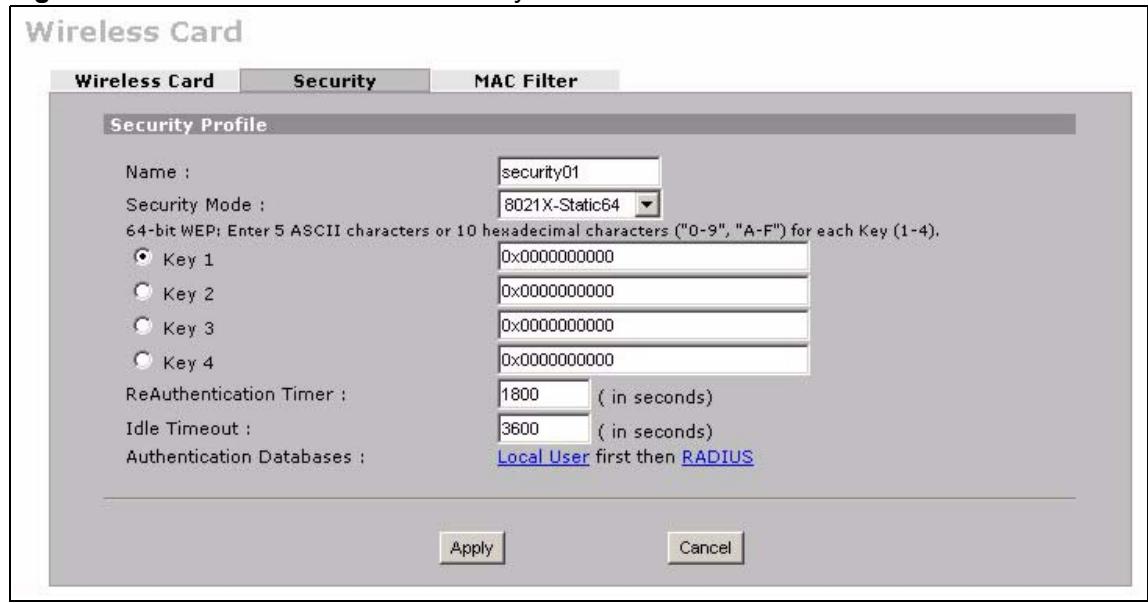
Figure 92 WIRELESS > Wi-Fi > Security: 802.1x + Static WEP
The following table describes the labels in this screen.
Table 36 WIRELESS > Wi-Fi > Security: 802.1x + Static WEP
| LABEL | DESCRIPTION |
| Name | Type a name to identify this security profile. |
| Security Mode | Select 8021X-Static64 or 8021X-Static128 from the drop-down list. |
| Key 1 to Key 4 | If you chose 8021X-Static64 in the Security Mode field, then enter any 5 characters (ASCII string) or 10 hexadecimal characters ("0-9", "A-F") preceded by 0x for each key. If you chose 8021X-Static128 in the Security Mode field, then enter 13 characters (ASCII string) or 26 hexadecimal characters ("0-9", "A-F") preceded by 0x for each key. There are four data encryption keys to secure your data from eavesdropping by unauthorized wireless users. The values for the keys must be set up exactly the same on the access points as they are on the wireless clients. |
| ReAuthentication Timer | Specify how often wireless clients have to resend user names and passwords in order to stay connected. Enter a time interval between 600 and 65535 seconds. If wireless client authentication is done using a RADIUS server, the reauthentication timer on the RADIUS server has priority. |
| Idle Timeout | The ZyXEL Device automatically disconnects a wireless client from the wireless network after a period of inactivity. The wireless client needs to send the username and password again before it can use the wireless network again. Some wireless clients may prompt users for a username and password; other clients may use saved login credentials. In either case, there is usually a short delay while the wireless client logs in to the wireless network again. This value is usually smaller when the wireless network is keeping track of how much time each wireless client is connected to the wireless network (for example, using an authentication server). If the wireless network is not keeping track of this information, you can usually set this value higher to reduce the number of delays caused by logging in again. Enter a time interval between 600 and 65535 seconds. |
| Authentication Databases | Click Local User to go to the Local User Database screen where you can view and/or edit the list of users and passwords. Click RADIUS to go to the RADIUS screen where you can configure the ZyXEL Device to check an external RADIUS server. |
| Apply | Click Apply to save your customized settings and exit this screen. |
| Cancel | Click Cancel to exit this screen without saving. |
8.4.5 WPA, WPA2, WPA2-MIX
Click WIRELESS > Wi-Fi > Security > Edit. Select WPA, WPA2 or WPA2-MIX from the Security Mode list.
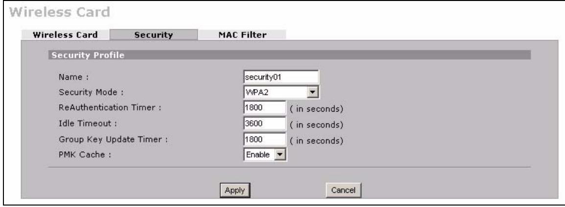
Figure 93 WIRELESS > Wi-Fi > Security: WPA, WPA2 or WPA2-MIX
The following table describes the labels in this screen.
Table 37 WIRELESS > Wi-Fi > Security: WPA, WPA2 or WPA2-MIX
| LABEL | DESCRIPTION |
| Name | Type a name to identify this security profile. |
| Security Mode | Select WPA, WPA2 or WPA2-MIX from the drop-down list. |
| ReAuthentication Timer | Specify how often wireless clients have to resend user names and passwords in order to stay connected. Enter a time interval between 600 and 65535 seconds. If wireless client authentication is done using a RADIUS server, the reauthentication timer on the RADIUS server has priority. |
| Idle Timeout | The ZyXEL Device automatically disconnects a wireless client from the wireless network after a period of inactivity. The wireless client needs to send the username and password again before it can use the wireless network again. Some wireless clients may prompt users for a username and password; other clients may use saved login credentials. In either case, there is usually a short delay while the wireless client logs in to the wireless network again. This value is usually smaller when the wireless network is keeping track of how much time each wireless client is connected to the wireless network (for example, using an authentication server). If the wireless network is not keeping track of this information, you can usually set this value higher to reduce the number of delays caused by logging in again. Enter a time interval between 600 and 65535 seconds. |
| Group Key Update Timer | The Group Key Update Timer is the rate at which the AP sends a new group key out to all clients. The re-keying process is the WPA equivalent of automatically changing the WEP key for an AP and all stations in a WLAN on a periodic basis. Setting of the Group Key Update Timer is also supported in WPA(2)-PSK mode. |
| PMK Cache | This field is available only when you select WPA2 or WPA2-MIX. When a wireless client moves from one AP's coverage area to another, it performs an authentication procedure (exchanging security information) with the new AP. Instead of re-authenticating a client each time it returns to the AP's coverage area, which can cause delays to time-sensitive applications, the AP and the client can store (or “cache”) and use information about their previous authentication. Select Enable to allow PMK (Pairwise Master Key) caching, or Disable to switch this feature off. |
| Apply | Click Apply to save your customized settings and exit this screen. |
| Cancel | Click Cancel to exit this screen without saving. |
8.4.6 WPA-PSK, WPA2-PSK, WPA2-PSK-MIX
Click WIRELESS > Wi-Fi > Security > Edit. Select WPA-PSK, WPA2-PSK or WPA2-PSK-MIX from the Security Mode list.
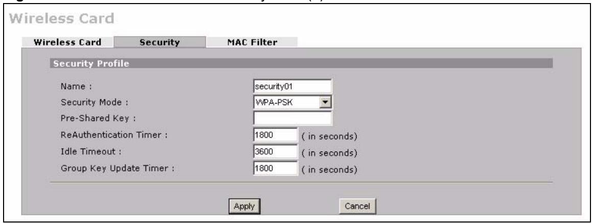
Figure 94 WIRELESS > Wi-Fi > Security: WPA(2)-PSK
The following table describes the labels in this screen.
Table 38 WIRELESS > Wi-Fi > Security: WPA(2)-PSK
| LABEL | DESCRIPTION |
| Name | Type a name to identify this security profile. |
| Security Mode | Select WPA-PSK, WPA2-PSK or WPA2-PSK-MIX from the drop-down list. |
| Pre-Shared Key | The encryption mechanisms used for WPA(2) and WPA(2)-PSK are the same. The only difference between the two is that WPA(2)-PSK uses a simple common password, instead of user-specific credentials.Type a pre-shared key from 8 to 63 case-sensitive ASCII characters (including spaces and symbols). |
| ReAuthentication Timer | Specify how often wireless clients have to resend user names and passwords in order to stay connected. Enter a time interval between 600 and 65535 seconds.If wireless client authentication is done using a RADIUS server, the reauthentication timer on the RADIUS server has priority. |
| Idle Timeout | The ZyXEL Device automatically disconnects a wireless client from the wireless network after a period of inactivity. The wireless client needs to send the username and password again before it can use the wireless network again. Some wireless clients may prompt users for a username and password; other clients may use saved login credentials. In either case, there is usually a short delay while the wireless client logs in to the wireless network again. This value is usually smaller when the wireless network is keeping track of how much time each wireless client is connected to the wireless network (for example, using an authentication server). If the wireless network is not keeping track of this information, you can usually set this value higher to reduce the number of delays caused by logging in again. Enter a time interval between 600 and 65535 seconds. |
| Group Key Update Timer | The Group Key Update Timer is the rate at which the AP sends a new group key out to all clients. The re-keying process is the WPA equivalent of automatically changing the WEP key for an AP and all stations in a WLAN on a periodic basis. Setting of the Group Key Update Timer is also supported in WPA(2)-PSK mode. |
| Apply | Click Apply to save your customized settings and exit this screen. |
| Cancel | Click Cancel to exit this screen without saving. |
8.5 MAC Filter
The MAC filter screen allows you to configure the ZyXEL Device to give exclusive access to specific devices (Allow) or exclude specific devices from accessing the ZyXEL Device (Deny). Every Ethernet device has a unique MAC (Media Access Control) address. The MAC address is assigned at the factory and consists of six pairs of hexadecimal characters, for example, 00:A0:C5:00:00:02. You need to know the MAC addresses of the devices to configure this screen.
To change your ZyXEL Device's MAC filter settings, click the WIRELESS > Wi-Fi > MAC Filter. The screen appears as shown.

To activate MAC filtering on a profile, select Enable from the Enable MAC Filtering drop-down list box in the Wireless Card > Edit screen and click Apply.
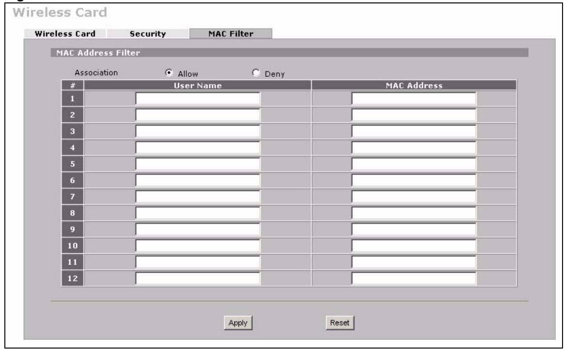
Figure 95 WIRELESS > Wi-Fi > MAC Filter
The following table describes the labels in this menu.
Table 39 WIRELESS > Wi-Fi > MAC Filter
| LABEL | DESCRIPTION |
| Association | Define the filter action for the list of MAC addresses in the MAC address filter table. Select Deny to block access to the router, MAC addresses not listed will be allowed to access the router. Select Allow to permit access to the router, MAC addresses not listed will be denied access to the router. |
| # | This is the index number of the MAC address. |
| User Name | Enter a descriptive name for the MAC address. |
| MAC Address | Enter the MAC addresses (in XX:XX:XX:XX:XX format) of the wireless stations that are allowed or denied access to the ZyXEL Device in these address fields. |
| Apply | Click Apply to save your changes back to the ZyXEL Device. |
| Reset | Click Reset to begin configuring this screen afresh. |
PART IV
Security
Firewall (167)
Certificates (195)
Authentication Server (191)
Firewall
This chapter shows you how to configure your ZyXEL Device's firewall.
9.1 Firewall Overview
The networking term firewall is a system or group of systems that enforces an access-control policy between two networks. It is generally a mechanism used to protect a trusted network from an untrusted network.
The ZyXEL Device physically separates the LAN, DMZ and the WAN and acts as a secure gateway for all data passing between the networks. The ZyXEL Device protects against Denial of Service (DoS) attacks, prevents theft, destruction and modification of data, and logs events.
Enable the firewall to protect your LAN computers from attacks by hackers on the Internet and control access between the LAN, DMZ and WAN. By default the firewall:
- allows traffic that originates from your LAN computers to go to all of the networks.
- blocks traffic that originates on the other networks from going to the LAN.
- allows traffic that originates on the WAN to go to the DMZ and protects your DMZ computers against DoS attacks.
The following figure illustrates the default firewall action. User A can initiate an IM (Instant Messaging) session from the LAN to the WAN (1). Return traffic for this session is also allowed (2). However other traffic initiated from the WAN is blocked (3 and 4).
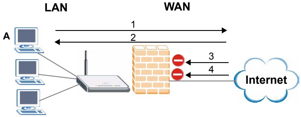
Figure 96 Default Firewall Action
Your customized rules take precedence and override the ZyXEL Device's default settings. The ZyXEL Device checks the source IP address, destination IP address and IP protocol type of network traffic against the firewall rules (in the order you list them). When the traffic matches a rule, the ZyXEL Device takes the action specified in the rule.
9.2 Packet Direction Matrix
The ZyXEL Device's packet direction matrix allows you to apply certain security settings (like firewall) to traffic flowing in specific directions.
For example, click SECURITY > FIREWALL to open the following screen. This screen configures general firewall settings.
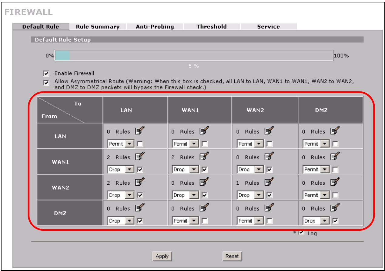
Figure 97 SECURITY > FIREWALL > Default Rule
Packets have a source and a destination. The packet direction matrix in the lower part of the screen sets what the ZyXEL Device does with packets traveling in a specific direction that do not match any of the firewall rules.
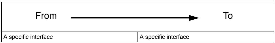
To set the ZyXEL Device to block traffic from WAN 1 from going to the DMZ interfaces, find where the From WAN1 row and the To DMZ column intersect and set the field to Drop as shown.
FIREWALL
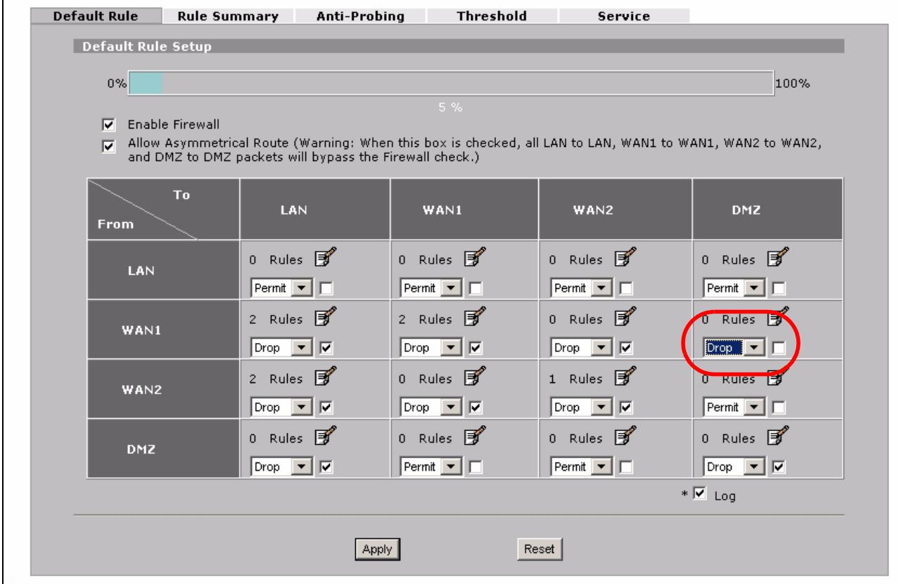
Figure 98 Default Block Traffic From WAN1 to DMZ Example
9.3 Packet Direction Examples
Firewall rules are grouped based on the direction of travel of packets to which they apply. This section gives some examples of why you might configure firewall rules for specific connection directions.
By default, the ZyXEL Device allows packets traveling in the following directions.:
- LAN to LAN These rules specify which computers on the LAN can manage the ZyXEL Device (remote management) and communicate between networks or subnets connected to the LAN interface (IP alias).

You can also configure the remote management settings to allow only a specific computer to manage the ZyXEL Device.
- LAN to WAN 1 These rules specify which computers on the LAN can access which computers or services connected to WAN 1. See Section 9.5 on page 171 for an example.
By default, the ZyXEL Device drops packets traveling in the following directions.
- WAN 1 to LAN
These rules specify which computers connected to WAN 1 can access which computers or services on the LAN. For example, you may create rules to:
- Allow certain types of traffic, such as Lotus Notes database synchronization, from specific hosts on the Internet to specific hosts on the LAN.
- Allow public access to a Web server on your protected network. You could also block certain IP addresses from accessing it.

You also need to configure NAT port forwarding (or full featured NAT address mapping rules) to allow computers on the WAN to access devices on the LAN. See Section 12.5.3 on page 236 for an example.
WAN to WAN
By default the ZyXEL Device stops computers connected to WAN1 or WAN2 from managing the ZyXEL Device or using the ZyXEL Device as a gateway to communicate with other computers on the WAN. You could configure one of these rules to allow a WAN computer to manage the ZyXEL Device.

You also need to configure the remote management settings to allow a WAN computer to manage the ZyXEL Device.
9.4 Security Considerations

Incorrectly configuring the firewall may block valid access or introduce security risks to the ZyXEL Device and your protected network. Use caution when creating or deleting firewall rules and test your rules after you configure them.
Consider these security ramifications before creating a rule:
1 Does this rule stop LAN users from accessing critical resources on the Internet? For example, if IRC is blocked, are there users that require this service?
2 Is it possible to modify the rule to be more specific? For example, if IRC is blocked for all users, will a rule that blocks just certain users be more effective?
3 Does a rule that allows Internet users access to resources on the LAN create a security vulnerability? For example, if FTP ports (TCP 20, 21) are allowed from the Internet to the LAN, Internet users may be able to connect to computers with running FTP servers.
4 Does this rule conflict with any existing rules?
Once these questions have been answered, adding rules is simply a matter of entering the information into the correct fields in the web configurator screens.
9.5 Firewall Rules Example
Suppose that your company decides to block all of the LAN users from using IRC (Internet Relay Chat) through the Internet. To do this, you would configure a LAN to WAN firewall rule that blocks IRC traffic from any source IP address from going to any destination address. You do not need to specify a schedule since you need the firewall rule to always be in effect. The following figure shows the results of this rule.
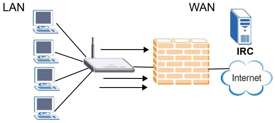
Figure 99 Blocking All LAN to WAN IRC Traffic Example
Your firewall would have the following configuration.
Table 40 Blocking All LAN to WAN IRC Traffic Example
| # | SOURCE | DESTINATION | SCHEDULE | SERVICE | ACTION |
| 1 | Any | Any | Any | IRC | Drop |
| Default | Any | Any | Any | Any | Allow |
- The first row blocks LAN access to the IRC service on the WAN.
- The second row is the firewall's default policy that allows all traffic from the LAN to go to the WAN.
The ZyXEL Device applies the firewall rules in order. So for this example, when the ZyXEL Device receives traffic from the LAN, it checks it against the first rule. If the traffic matches (if it is IRC traffic) the firewall takes the action in the rule (drop) and stops checking the firewall rules. Any traffic that does not match the first firewall rule will match the default rule and the ZyXEL Device forwards it.
Now suppose that your company wants to let the CEO use IRC. You can configure a LAN to WAN firewall rule that allows IRC traffic from the IP address of the CEO's computer. In order to make sure that the CEO's computer always uses the same IP address, make sure it either:
has a static IP address,
- or you configure a static DHCP entry for it so the ZyXEL Device always assigns it the same IP address (see Section 5.8 on page 106 for information on static DHCP).
Now you configure a LAN to WAN firewall rule that allows IRC traffic from the IP address of the CEO's computer (192.168.1.7 for example) to go to any destination address. You do not need to specify a schedule since you want the firewall rule to always be in effect. The following figure shows the results of your two custom rules.
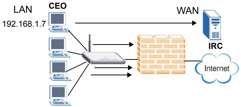
Figure 100 Limited LAN to WAN IRC Traffic Example
Your firewallwould have the following configuration.
Table 41 Limited LAN to WAN IRC Traffic Example
| # | SOURCE | DESTINATION | SCHEDULE | SERVICE | ACTION |
| 1 | 192.168.1.7 | Any | Any | IRC | Allow |
| 2 | Any | Any | Any | IRC | Drop |
| Default | Any | Any | Any | Any | Allow |
- The first row allows the LAN computer at IP address 192.168.1.7 to access the IRC service on the WAN.
- The second row blocks LAN access to the IRC service on the WAN.
- The third row is (still) the firewall's default policy of allowing all traffic from the LAN to go to the WAN.
The rule for the CEO must come before the rule that blocks all LAN to WAN IRC traffic. If the rule that blocks all LAN to WAN IRC traffic came first, the CEO's IRC traffic would match that rule and the ZyXEL Device would drop it and not check any other firewall rules.
9.6 Asymmetrical Routes
If an alternate gateway on the LAN has an IP address in the same subnet as the ZyXEL Device's LAN IP address, return traffic may not go through the ZyXEL Device. This is called an asymmetrical or "triangle" route. This causes the ZyXEL Device to reset the connection, as the connection has not been acknowledged.
You can have the ZyXEL Device permit the use of asymmetrical route topology on the network (not reset the connection).
Allowing asymmetrical routes may let traffic from the WAN go directly to the LAN without passing through the ZyXEL Device. A better solution is to use IP alias to put the ZyXEL Device and the backup gateway on separate subnets.
9.6.1 Asymmetrical Routes and IP Alias
You can use IP alias instead of allowing asymmetrical routes. IP Alias allow you to partition your network into logical sections over the same interface.
By putting your LAN and Gateway A in different subnets, all returning network traffic must pass through the ZyXEL Device to your LAN. The following steps describe such a scenario.
1 A computer on the LAN initiates a connection by sending a SYN packet to a receiving server on the WAN.
2 The ZyXEL Device reroutes the packet to Gateway A, which is in Subnet 2.
3 The reply from the WAN goes to the ZyXEL Device.
4 The ZyXEL Device then sends it to the computer on the LAN in Subnet 1.
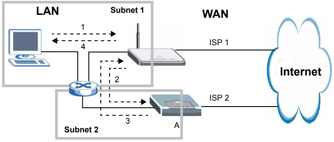
Figure 101 Using IP Alias to Solve the Triangle Route Problem
9.7 Firewall Default Rule
Click SECURITY > FIREWALL to open the Default Rule screen.
Use this screen to configure general firewall settings.
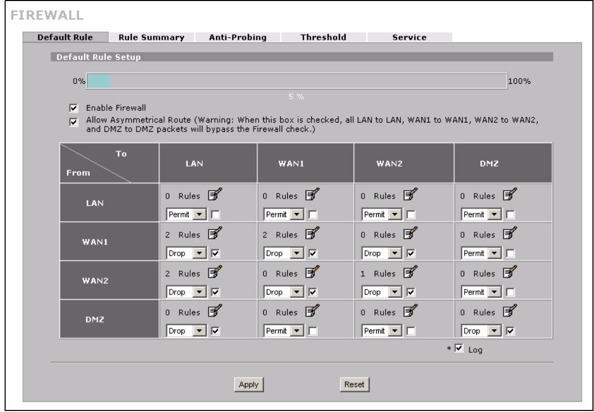
Figure 102 SECURITY > FIREWALL > Default Rule
The following table describes the labels in this screen.
Table 42 SECURITY > FIREWALL > Default Rule
| LABEL | DESCRIPTION |
| 0-100% | This bar displays the percentage of the ZyXEL Device's firewall rules storage space that is currently in use. When the storage space is almost full, you should consider deleting unnecessary firewall rules before adding more firewall rules. |
| Enable Firewall | Select this check box to activate the firewall. TheZyXELDevice performs access control and protects against Denial of Service (DoS) attacks when the firewall is activated.Note:When you activate the firewall, all current connections through theZyXELDevice are dropped when you apply your changes. |
| AllowAsymmetricalRoute | If an alternate gateway on the LAN has an IP address in the same subnet as theZyXELDevice's LAN IP address, return traffic may not go through theZyXELDevice. This is called an asymmetrical or "triangle" route. This causes theZyXELDevice to reset the connection, as the connection has not been acknowledged. Select this check box to have theZyXELDevice permit the use of asymmetricalroute topology on the network (not reset the connection).Note:Allowing asymmetrical routes may let traffic from the WAN go directly to the LAN without passing through theZyXELDevice.A better solution is to use IP alias to put theZyXELDeviceand the backup gateway on separate subnets. See Section 9.6.1 on page 173 for an example. |
| From, To | The firewall rules are grouped by the direction of packet travel. This displays the number of rules for each packet direction. Click the edit icon to go to a summary screen of the rules for that packet direction. Here is an example description of the directions of travel. From LAN To LAN means packets traveling from a computer on one LAN subnet to a computer on another LAN subnet on the LAN interface of the ZyXEL Device or the ZyXEL Device itself. The ZyXEL Device does not apply the firewall to packets traveling from a LAN computer to another LAN computer on the same subnet. Use the drop-down list box to set the firewall's default actions based on the direction of travel of packets. Select Drop to silently discard the packets without sending a TCP reset packet or an ICMP destination-unreachable message to the sender. Select Reject to deny the packets and send a TCP reset packet (for a TCP packet) or an ICMP destination-unreachable message (for a UDP packet) to the sender. Select Permit to allow the passage of the packets. |
| Log | Select the check box next to a direction of packet travel to create a log when the above action is taken for packets that are traveling in that direction and do not match any of your customized rules. |
| Apply | Click Apply to save your changes. |
| Reset | Click Reset to begin configuring this screen afresh. |
9.8 Firewall Rule Summary
Click SECURITY > FIREWALL > Rule Summary to open the screen. This screen displays a list of the configured firewall rules.

The ordering of your rules is very important as rules are applied in the order that they are listed.
See Section 9.1 on page 167 for more information about the firewall.
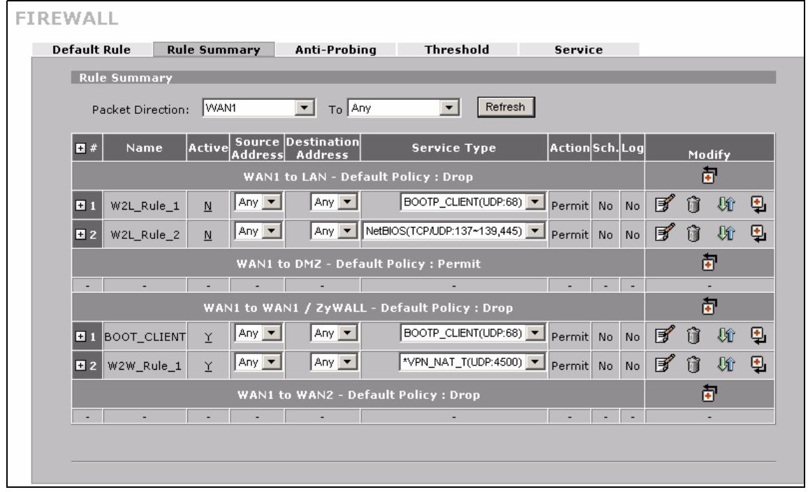
Figure 103 SECURITY > FIREWALL > Rule Summary
The following table describes the labels in this screen.
Table 43 SECURITY > FIREWALL > Rule Summary
| LABEL | DESCRIPTION |
| Packet Direction | Use the drop-down list boxes and click Refresh to select a direction of travel of packets for which you want to display firewall rules. |
| +/- | In the heading row, click + to expand or - to collapse the Source Address, Destination Address and Service Type drop down lists for all of the displayed rules. |
| Default Policy | This field displays the default action you selected in the Default Rule screen for the packet direction displayed. |
| The following fields summarize the rules you have created that apply to traffic traveling in the selected packet direction. The firewall rules that you configure (summarized below) take priority over the general firewall action settings above. | |
| # | This is your firewall rule number. The ordering of your rules is important as rules are applied in turn. Click + to expand or - to collapse the Source Address, Destination Address and Service Type drop down lists. |
| Name | This is the name of the firewall rule. |
| Active | This field displays whether a firewall is turned on (Y) or not (N). Click the setting to change it. |
| Source Address | This drop-down list box displays the source addresses or ranges of addresses to which this firewall rule applies. Please note that a blank source or destination address is equivalent to Any. |
| Destination Address | This drop-down list box displays the destination addresses or ranges of addresses to which this firewall rule applies. Please note that a blank source or destination address is equivalent to Any. |
| Service Type | This drop-down list box displays the services to which this firewall rule applies.Custom services have an * before the name. See Appendix D on page 385 for a list of common services. |
Table 43 SECURITY > FIREWALL > Rule Summary
| LABEL | DESCRIPTION |
| Action | This field displays whether the firewall silently discards packets (Drop), discards packets and sends a TCP reset packet or an ICMP destination-unreachable message to the sender (Reject) or allows the passage of packets (Permit). |
| Sch. | This field tells you whether a schedule is specified (Yes) or not (No). |
| Log | This field shows you whether a log is created when packets match this rule (Yes) or not (No). |
| Modify | Click the edit icon to go to the screen where you can edit the rule. Click the delete icon to delete an existing firewall rule. A window displays asking you to confirm that you want to delete the firewall rule. Note that subsequent firewall rules move up by one when you take this action. Click the insert icon to display the screen where you can configure a new firewall rule. The insert icon at the top of the row creates the new firewall rule before the others. The individual firewall rule insert icons create a new firewall rule after the row's firewall rule. Click the move icon, type an index number, and press Enter to move the rule to the number that you typed. The ordering of your rules is important as they are applied in order of their numbering. |
9.8.1 Firewall Edit Rule
In the Rule Summary screen, click the edit icon or the insert icon to display the Firewall Edit Rule screen.
Use this screen to create or edit a firewall rule. Refer to the following table for information on the labels.
See Section 9.1 on page 167 for more information about the firewall.
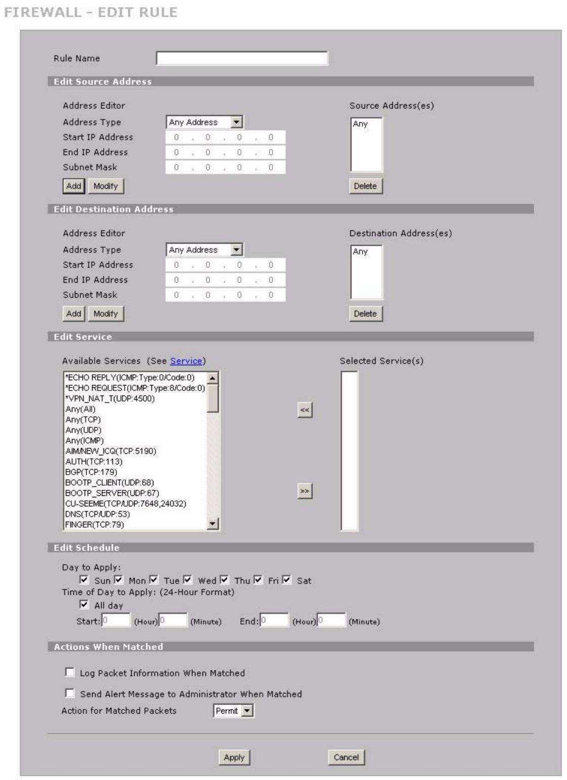
Figure 104 SECURITY > FIREWALL > Rule Summary > Edit
The following table describes the labels in this screen.
Table 44 SECURITY > FIREWALL > Rule Summary > Edit
| LABEL | DESCRIPTION |
| Rule Name | Enter a descriptive name of up to 31 printable ASCII characters (except Extended ASCII characters) for the firewall rule. Spaces are allowed. |
| Edit Source/ Destination Address | |
| Address Type | Do you want your rule to apply to packets with a particular (single) IP, a range of IP addresses (for example 192.168.1.10 to 192.169.1.50), a subnet or any IP address? Select an option from the drop-down list box that includes: Single Address, Range Address, Subnet Address and Any Address. |
| Start IP Address | Enter the single IP address or the starting IP address in a range here. |
| End IP Address | Enter the ending IP address in a range here. |
| Subnet Mask | Enter the subnet mask here, if applicable. |
| Add | Click Add to add a new address to the Source or Destination Address(es) box. You can add multiple addresses, ranges of addresses, and/or subnets. |
| Modify | To edit an existing source or destination address, select it from the box and click Modify. |
| Delete | Highlight an existing source or destination address from the Source or Destination Address(es) box above and click Delete to remove it. |
| Edit Service | |
| Available/ Selected Services | Highlight a service from the Available Services box on the left, then click >> to add it to the Selected Service(s) box on the right. To remove a service, highlight it in the Selected Service(s) box on the right, then click <<. Next to the name of a service, two fields appear in brackets. The first field indicates the IP protocol type (TCP, UDP, or ICMP). The second field indicates the IP port number that defines the service. (Note that there may be more than one IP protocol type). For example, look at the DNS entry, (UDP/TCP:53) means UDP port 53 and TCP port 53. Click the Service link to go to the Service screen where you can configure custom service ports. See Appendix D on page 385 for a list of commonly used services and port numbers. You can use the [CTRL] key and select multiple services at once. |
| Edit Schedule | |
| Day to Apply | Select everyday or the day(s) of the week to apply the rule. |
| Time of Day to Apply (24-Hour Format) | Select All Day or enter the start and end times in the hour-minute format to apply the rule. |
| Actions When Matched | |
| Log Packet Information When Matched | This field determines if a log for packets that match the rule is created (Yes) or not (No). Go to the Log Settings page and select the Access Control logs category to have the ZyXEL Device record these logs. |
| Send Alert Message to Administrator When Matched | Select the check box to have the ZyXEL Device generate an alert when the rule is matched. |
Table 44 SECURITY > FIREWALL > Rule Summary > Edit
| LABEL | DESCRIPTION |
| Action for Matched Packets | Use the drop-down list box to select what the firewall is to do with packets that match this rule. Select Drop to silently discard the packets without sending a TCP reset packet or an ICMP destination-unreachable message to the sender. Select Reject to deny the packets and send a TCP reset packet (for a TCP packet) or an ICMP destination-unreachable message (for a UDP packet) to the sender. Select Permit to allow the passage of the packets. Note: You also need to configure NAT port forwarding (or full featured NAT address mapping rules) if you want to allow computers on the WAN to access devices on the LAN. Note: You may also need to configure the remote management settings if you want to allow a WAN computer to manage the ZyxEL Device or restrict management from the LAN. |
| Apply | Click Apply to save your customized settings and exit this screen. |
| Cancel | Click Cancel to exit this screen without saving. |
9.9 Anti-Probing
Click SECURITY > FIREWALL > Anti-Probing to open the following screen. Configure this screen to help keep the ZyXEL Device hidden from probing attempts. You can specify which of the ZyXEL Device's interfaces will respond to Ping requests and whether or not the ZyXEL Device is to respond to probing for unused ports.
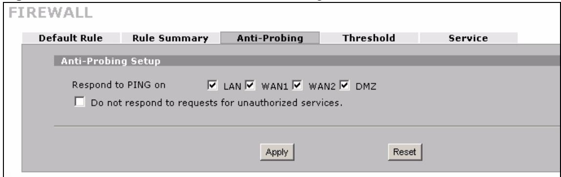
Figure 105 SECURITY > FIREWALL > Anti-Probing
The following table describes the labels in this screen.
Table 45 SECURITY > FIREWALL > Anti-Probing
| LABEL | DESCRIPTION |
| Respond to PING on | Select the check boxes of the interfaces that you want to reply to incoming Ping requests.Clear an interface's check box to have the ZyXEL Device not respond to any Ping requests that come into that interface. |
| Do not respond to requests for unauthorized services. | Select this option to prevent hackers from finding the ZyXEL Device by probing for unused ports. If you select this option, the ZyXEL Device will not respond to port request(s) for unused ports, thus leaving the unused ports and the ZyXEL Device unseen. If this option is not selected, the ZyXEL Device will reply with an ICMP port unreachable packet for a port probe on its unused UDP ports and a TCP reset packet for a port probe on its unused TCP ports.Note that the probing packets must first traverse the ZyXEL Device's firewall rule checks before reaching this anti-probing mechanism. Therefore if a firewall rule stops a probing packet, the ZyXEL Device reacts based on the firewall rule to either send a TCP reset packet for a blocked TCP packet (or an ICMP port-unreachable packet for a blocked UDP packets) or just drop the packets without sending a response packet. |
| Apply | Click Apply to save your changes. |
| Reset | Click Reset to begin configuring this screen afresh. |
9.10 Firewall Thresholds
For DoS attacks, the ZyXEL Device uses thresholds to determine when to start dropping sessions that do not become fully established (half-open sessions). These thresholds apply globally to all sessions.
For TCP, half-open means that the session has not reached the established state-the TCP three-way handshake has not yet been completed. Under normal circumstances, the application that initiates a session sends a SYN (synchronize) packet to the receiving server. The receiver sends back an ACK (acknowledgment) packet and its own SYN, and then the initiator responds with an ACK (acknowledgment). After this handshake, a connection is established.
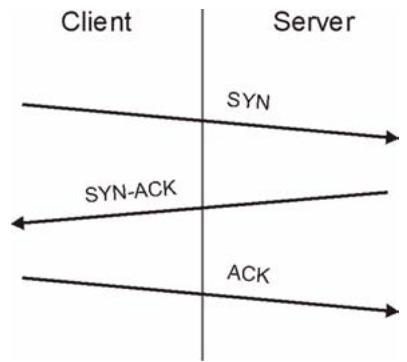
Figure 106 Three-Way Handshake
For UDP, half-open means that the firewall has detected no return traffic. An unusually high number (or arrival rate) of half-open sessions could indicate a DOS attack.
9.10.1 Threshold Values
If everything is working properly, you probably do not need to change the threshold settings as the default threshold values should work for most small offices. Tune these parameters when you believe the ZyXEL Device has been receiving DoS attacks that are not recorded in the logs or the logs show that the ZyXEL Device is classifying normal traffic as DoS attacks.
Factors influencing choices for threshold values are:
1 The maximum number of opened sessions.
2 The minimum capacity of server backlog in your LAN network.
3 The CPU power of servers in your LAN network.
4 Network bandwidth.
5 Type of traffic for certain servers.
Reduce the threshold values if your network is slower than average for any of these factors (especially if you have servers that are slow or handle many tasks and are often busy).
If you often use P2P applications such as file sharing with eMule or eDonkey, it's recommended that you increase the threshold values since lots of sessions will be established during a small period of time and the ZyXEL Device may classify them as DoS attacks.
9.11 Threshold Screen
Click SECURITY > FIREWALL > Threshold to bring up the next screen. The global values specified for the threshold and timeout apply to all TCP connections.
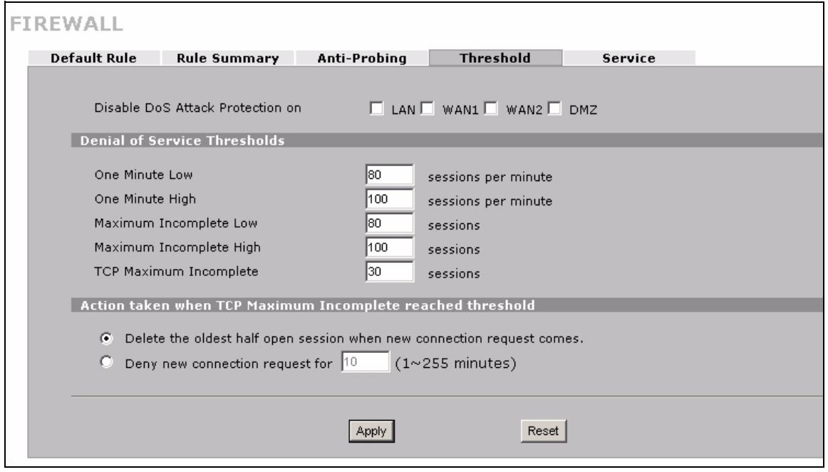
Figure 107 SECURITY > FIREWALL > Threshold
The following table describes the labels in this screen.
Table 46 SECURITY > FIREWALL > Threshold
| LABEL | DESCRIPTION |
| Disable DoS Attack Protection on | Select the check boxes of any interfaces for which you want the ZyXEL Device to not use the Denial of Service protection thresholds. This disables DoS protection on the selected interface.You may want to disable DoS protection for an interface if the ZyXEL Device is treating valid traffic as DoS attacks. Another option would be to raise the thresholds. |
| Denial of Service Thresholds | The ZyXEL Device measures both the total number of existing half-open sessions and the rate of session establishment attempts. Both TCP and UDP half-open sessions are counted in the total number and rate measurements.Measurements are made once a minute. |
| One Minute Low | This is the rate of new half-open sessions per minute that causes the firewall to stop deleting half-open sessions. The ZyXEL Device continues to delete half-open sessions as necessary, until the rate of new connection attempts drops below this number. |
| One Minute High | This is the rate of new half-open sessions per minute that causes the firewall to start deleting half-open sessions. When the rate of new connection attempts rises above this number, the ZyXEL Device deletes half-open sessions as required to accommodate new connection attempts.For example, if you set the one minute high to 100, the ZyXEL Device starts deleting half-open sessions when more than 100 session establishment attempts have been detected in the last minute. It stops deleting half-open sessions when the number of session establishment attempts detected in a minute goes below the number set as the one minute low. |
| Maximum Incomplete Low | This is the number of existing half-open sessions that causes the firewall to stop deleting half-open sessions. The ZyXEL Device continues to delete half-open requests as necessary, until the number of existing half-open sessions drops below this number. |
| Maximum Incomplete High | This is the number of existing half-open sessions that causes the firewall to start deleting half-open sessions. When the number of existing half-open sessions rises above this number, the ZyXEL Device deletes half-open sessions as required to accommodate new connection requests. Do not set Maximum Incomplete High to lower than the current Maximum Incomplete Low number.For example, if you set the maximum incomplete high to 100, the ZyXEL Device starts deleting half-open sessions when the number of existing half-open sessions rises above 100. It stops deleting half-open sessions when the number of existing half-open sessions drops below the number set as the maximum incomplete low. |
| TCP Maximum Incomplete | An unusually high number of half-open sessions with the same destination host address could indicate that a DoS attack is being launched against the host.Specify the number of existing half-open TCP sessions with the same destination host IP address that causes the firewall to start dropping half-open sessions to that same destination host IP address. Enter a number between 1 and 256. As a general rule, you should choose a smaller number for a smaller network, a slower system or limited bandwidth. The ZyXEL Device sends alerts whenever the TCP Maximum Incomplete is exceeded. |
| Action taken when TCP Maximum Incomplete reached threshold | Select the action that ZyXEL Device should take when the TCP maximum incomplete threshold is reached. You can have the ZyXEL Device either:Delete the oldest half open session when a new connection request comes.orDeny new connection requests for the number of minutes that you specify (between 1 and 256). |
| Apply | Click Apply to save your changes. |
| Reset | Click Reset to begin configuring this screen afresh. |
9.12 Service
Click SECURITY > FIREWALL > Service to open the screen as shown next. Use this screen to configure custom services for use in firewall rules or view the services that are predefined in the ZyXEL Device.
See Section 9.1 on page 167 for more information about the firewall.
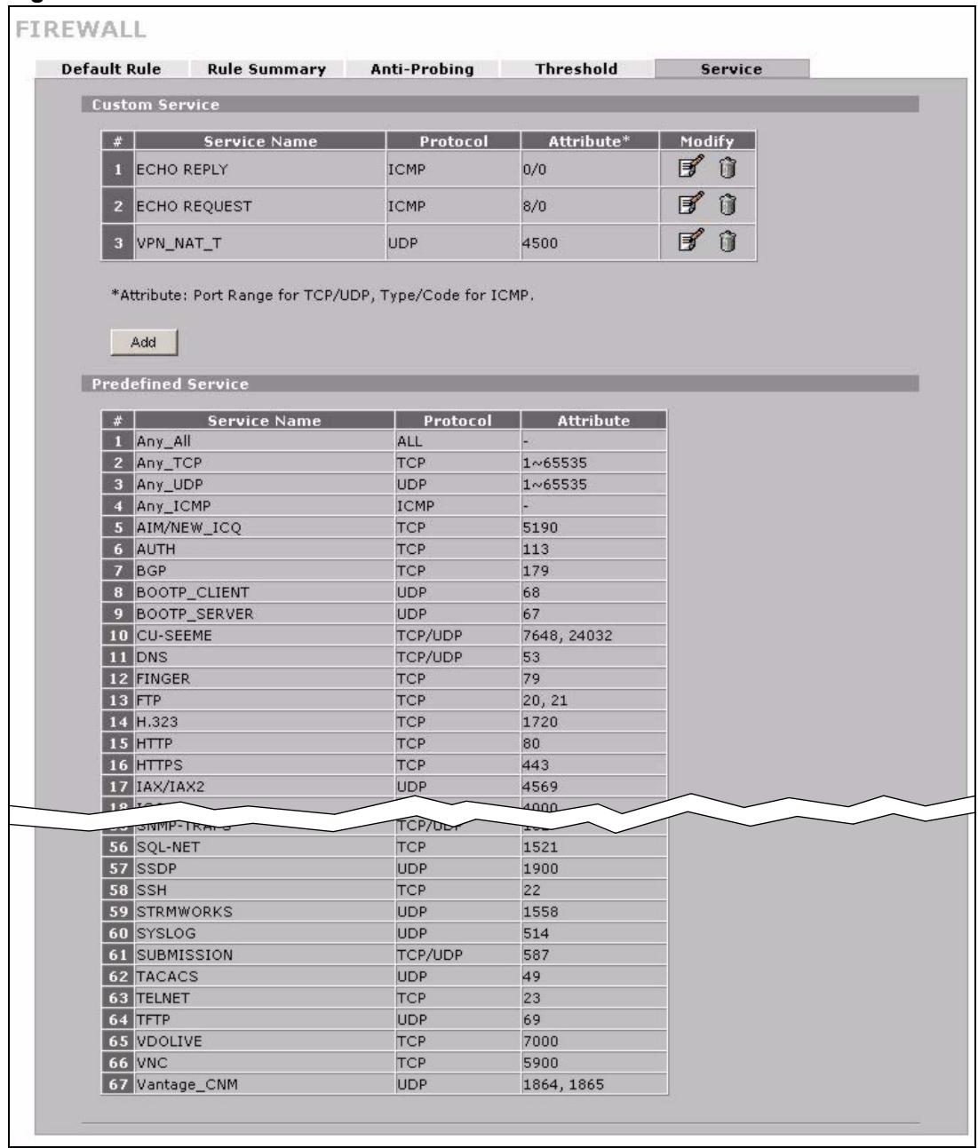
Figure 108 SECURITY > FIREWALL > Service
The following table describes the labels in this screen.
Table 47 SECURITY > FIREWALL > Service
| LABEL | DESCRIPTION |
| Custom Service | This table shows all configured custom services. |
| # | This is the index number of the custom service. |
| Service Name | This is the name of the service. |
| Protocol | This is the IP protocol type. If you selected Custom, this is the IP protocol value you entered. |
| Attribute | This is the IP port number or ICMP type and code that defines the service. |
| Modify | Click the edit icon to go to the screen where you can edit the service. Click the delete icon to remove an existing service. A window displays asking you to confirm that you want to delete the service. Note that subsequent services move up by one when you take this action. |
| Add | Click this button to bring up the screen that you use to configure a new custom service that is not in the predefined list of services. |
| Predefined Service | This table shows all the services that are already configured for use in firewall rules. See Appendix D on page 385 for a list of common services. |
| # | This is the index number of the predefined service. |
| Service Name | This is the name of the service. |
| Protocol | This is the IP protocol type. There may be more than one IP protocol type. |
| Attribute | This is the IP port number or ICMP type and code that defines the service. |
9.12.1 Firewall Edit Custom Service
Click SECURITY > FIREWALL > Service > Add to display the following screen. Use this screen to configure a custom service entry not is not predefined in the ZyXEL Device. See Appendix D on page 385 the user's guide appendices for a list of commonly used services and port numbers.
See Section 9.1 on page 167 for more information about the firewall.
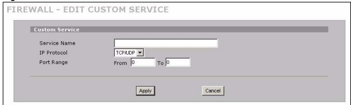
Figure 109 Firewall Edit Custom Service
The following table describes the labels in this screen.
Table 48 SECURITY > FIREWALL > Service > Add
| LABEL | DESCRIPTION |
| Service Name | Enter a descriptive name of up to 31 printable ASCII characters (except Extended ASCII characters) for the custom service. You cannot use the “(”character. Spaces are allowed. |
| IP Protocol | Choose the IP protocol (TCP, UDP, TCP/UDP, ICMP or Custom) that defines your customized service from the drop down list box.If you select Custom, specify the protocol's number. For example, ICMP is 1, TCP is 6, UDP is 17 and so on. |
| Port Range | Enter the port number (from 1 to 255) that defines the customized serviceTo specify one port only, enter the port number in the From field and enter it again in the To field.To specify a span of ports, enter the first port in the From field and enter the last port in the To field. |
| Type/Code | This field is available only when you select ICMP in the IP Protocol field.The ICMP messages are identified by their types and in some cases codes.Enter the type number in the Type field and select the Code radio button and enter the code number if any. |
| Apply | Click Apply to save your customized settings and exit this screen. |
| Cancel | Click Cancel to exit this screen without saving. |
9.13 My Service Firewall Rule Example
The following Internet firewall rule example allows a hypothetical My Service connection from the Internet.
1 In the Service screen, click Add to open the Edit Custom Service screen.
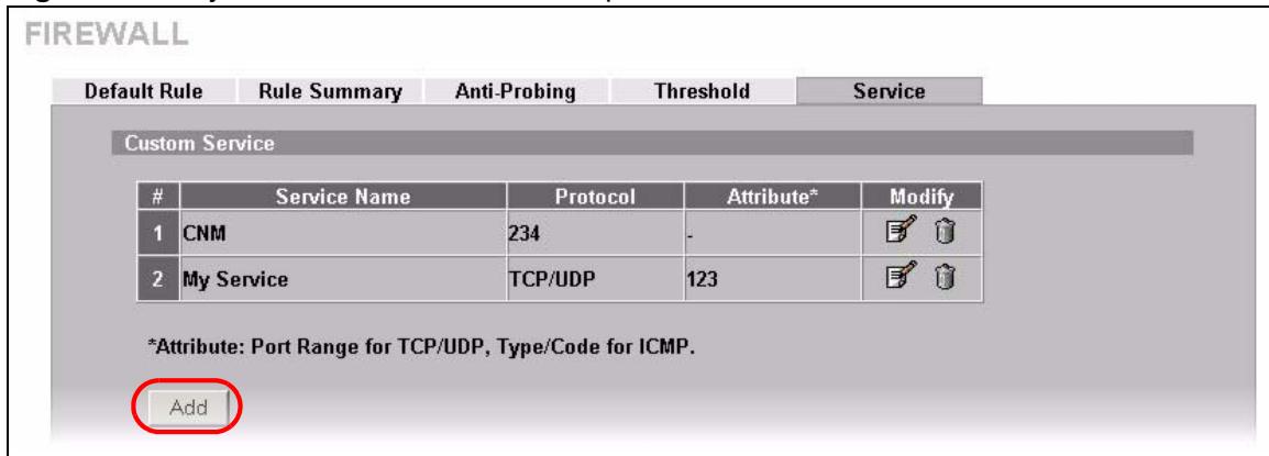
Figure 110 My Service Firewall Rule Example: Service
2 Configure it as follows and click Apply.
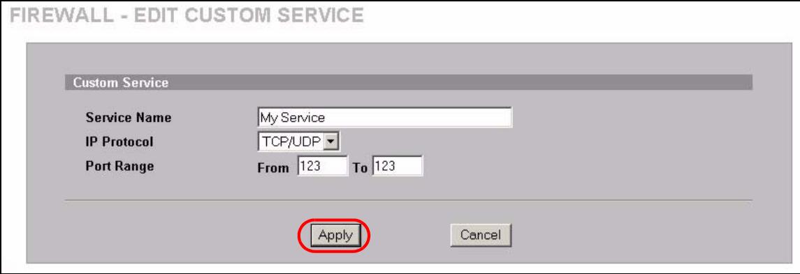
Figure 111 My Service Firewall Rule Example: Edit Custom Service
3 Click Rule Summary. Select WAN1 and LAN from the Packet Direction drop-down list boxes and click Refresh to display existing firewall rules for the selected direction of travel of packets.
4 Click the insert icon at the top of the row to create the new firewall rule before the others.
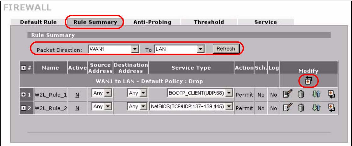
Figure 112 My Service Firewall Rule Example: Rule Summary
5 The Edit Rule screen displays. Enter the name of the firewall rule.
6 Select Any in the Destination Address(es) box and then click Delete.
7 Configure the destination address fields as follows and click Add.
Figure 113 My Service Firewall Rule Example: Rule Edit: Source and Destination Addresses
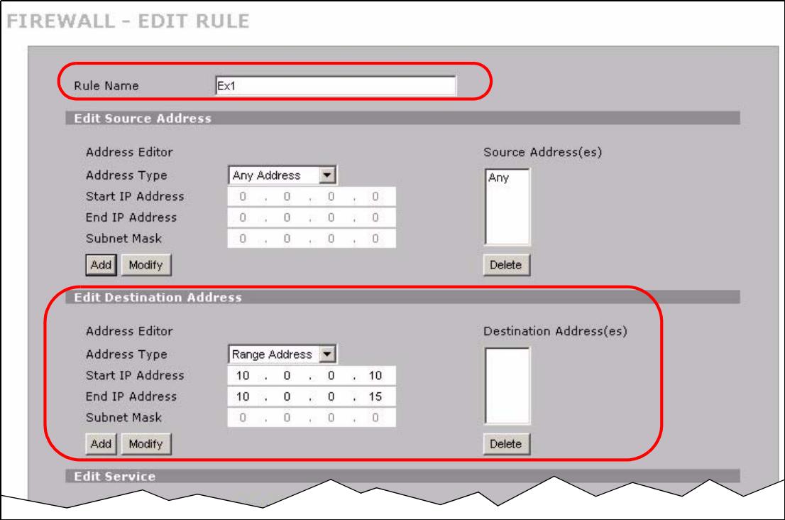
8 In the Edit Service section, use the arrows between Available Services and Selected Service(s) to configure it as follows. Click Apply when you are done.

Custom services show up with an * before their names in the Services list boxes and the Rule Summary screen's Service Type list box.
Figure 114 My Service Firewall Rule Example: Edit Rule: Service Configuration
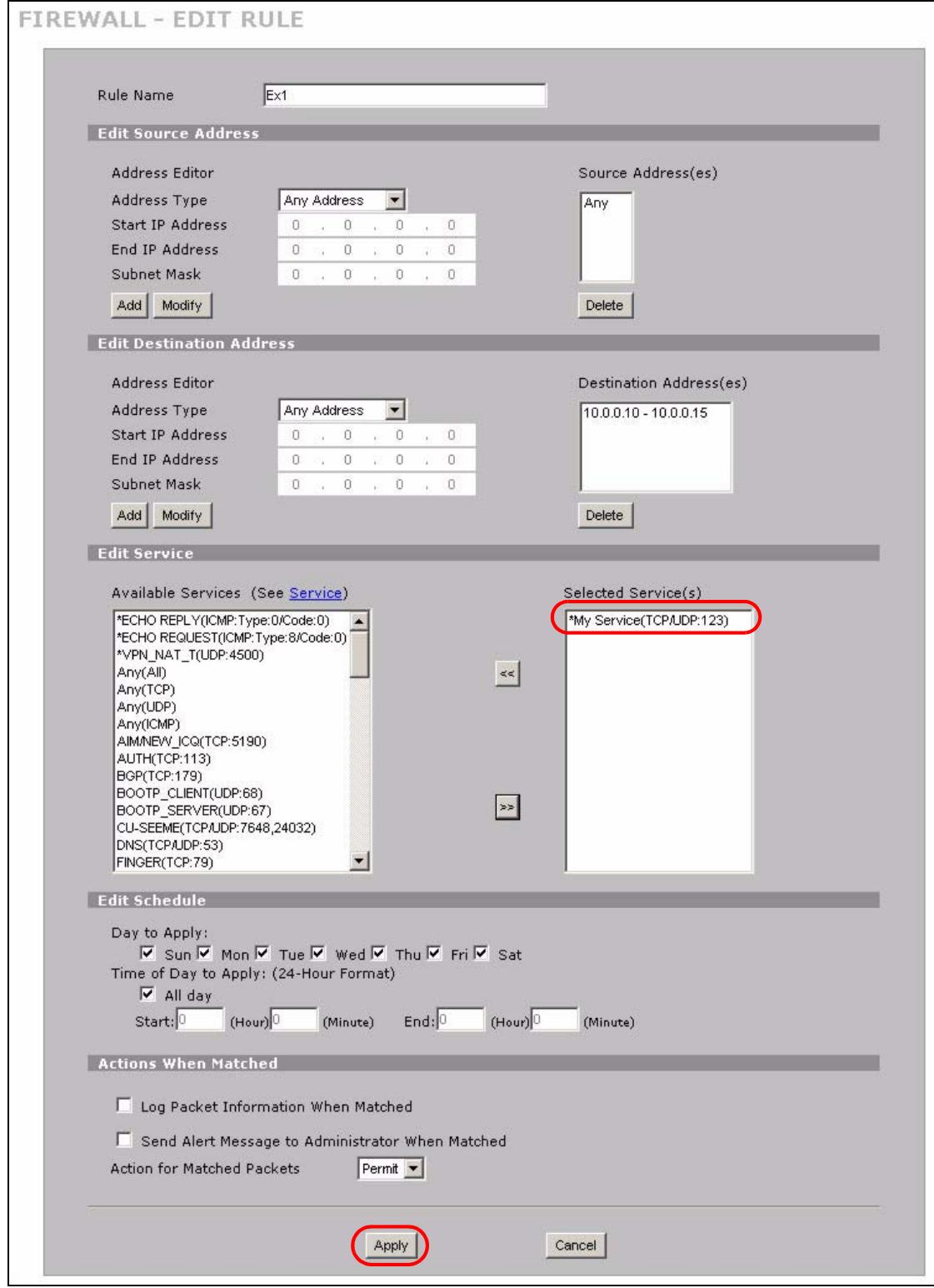
Rule 1 allows a My Service connection from WAN 1 to IP addresses 10.0.0.10 through 10.0.0.15 on the LAN.
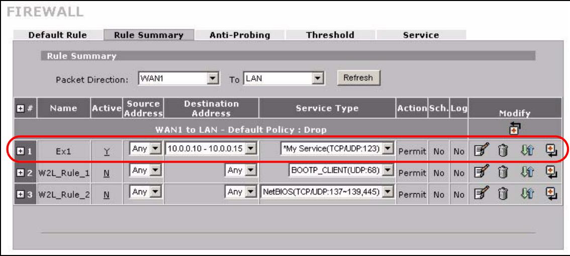
Figure 115 My Service Firewall Rule Example: Rule Summary: Completed
Authentication Server
This chapter discusses how to configure the ZyXEL Device's authentication server feature.
10.1 Authentication Server Overview
A ZyXEL Device can use either the local user database internal to the ZyXEL Device or an external RADIUS server to authenticate wireless clients. See Appendix E on page 389 for more information about RADIUS.
10.2 Local User Database
Click SECURITY > AUTHSERVER to open the Local User Database screen. The local user database is a list of user profiles stored on the ZyXEL Device. The ZyXEL Device can use this list of user profiles to authenticate users. Use this screen to change your ZyXEL Device's list of user profiles.
AUTHENTICATIONSERVER
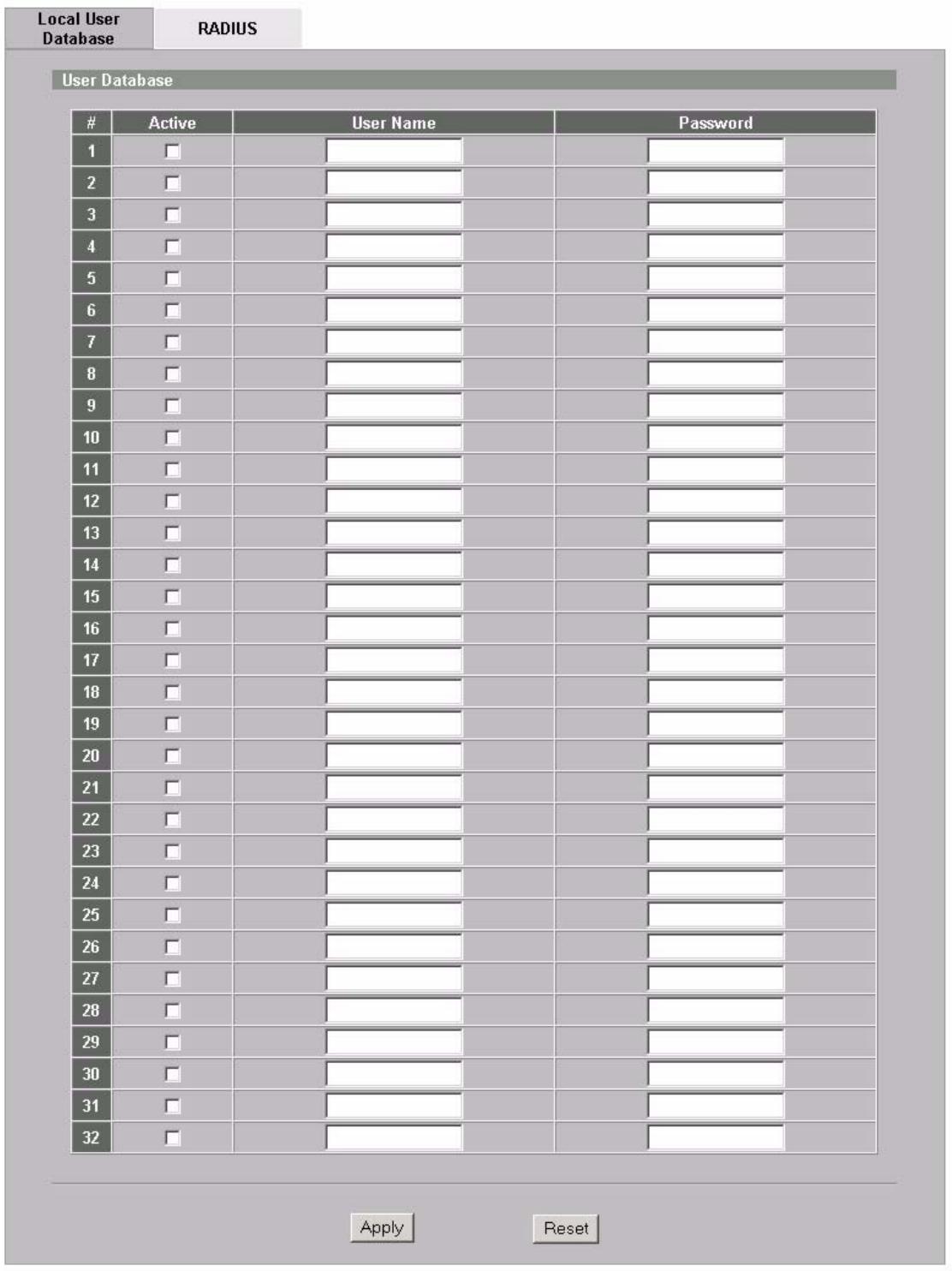
Figure 116 SECURITY > AUTHSERVER > Local User Database
The following table describes the labels in this screen.
Table 49 SECURITY > AUTH SERVER > Local User Database
| LABEL | DESCRIPTION |
| Active | Select this check box to enable the user profile. |
| UserID | Enter the user name of the user profile. |
| Password | Enter a password up to 31 characters long for this user profile. |
| Apply | Click Apply to save your changes. |
| Reset | Click Reset to begin configuring this screen afresh. |
10.3 RADIUS
Click SECURITY > AUTH_SERVER > RADIUS to open the RADIUS screen. Configure this screen to use an external RADIUS server to authenticate users.
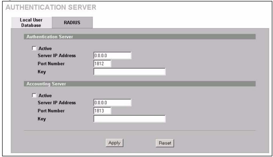
Figure 117 SECURITY > AUTH SERVER > RADIUS
The following table describes the labels in this screen.
Table 50 SECURITY > AUTH SERVER > RADIUS
| LABEL | DESCRIPTION |
| Authentication Server | |
| Active | Select the check box to enable user authentication through an external authentication server.Clear the check box to enable user authentication using the local user profile on the ZyXEL Device. |
| Server IP Address | Enter the IP address of the external authentication server in dotted decimal notation. |
| Port Number | The default port of the RADIUS server for authentication is 1812.You need not change this value unless your network administrator instructs you to do so with additional information. |
Table 50 SECURITY > AUTH SERVER > RADIUS
| LABEL | DESCRIPTION |
| Key | Enter a password (up to 31 alphanumeric characters) as the key to be shared between the external authentication server and the ZyXEL Device. The key is not sent over the network. This key must be the same on the external authentication server and ZyXEL Device. |
| Accounting Server | |
| Active | Select the check box to enable user accounting through an external authentication server. |
| Server IP Address | Enter the IP address of the external accounting server in dotted decimal notation. |
| Port Number | The default port of the RADIUS server for accounting is 1813. You need not change this value unless your network administrator instructs you to do so with additional information. |
| Key | Enter a password (up to 31 alphanumeric characters) as the key to be shared between the external accounting server and the ZyXEL Device. The key is not sent over the network. This key must be the same on the external accounting server and ZyXEL Device. |
| Apply | Click Apply to save your changes. |
| Reset | Click Reset to begin configuring this screen afresh. |
Certificates
This chapter gives background information about public-key certificates and explains how to use them.
11.1 Certificates Overview
The ZyXEL Device can use certificates (also called digital IDs) to authenticate users. Certificates are based on public-private key pairs. A certificate contains the certificate owner's identity and public key. Certificates provide a way to exchange public keys for use in authentication.
A Certification Authority (CA) issues certificates and guarantees the identity of each certificate owner. There are commercial certification authorities like CyberTrust or VeriSign and government certification authorities. You can use the ZyXEL Device to generate certification requests that contain identifying information and public keys and then send the certification requests to a certification authority.
When using public-key cryptography for authentication, each host has two keys. One key is public and can be made openly available; the other key is private and must be kept secure. Public-key encryption in general works as follows.
1 Tim wants to send a private message to Jenny. Tim generates a public-private key pair. What is encrypted with one key can only be decrypted using the other.
2 Tim keeps the private key and makes the public key openly available.
3 Tim uses his private key to encrypt the message and sends it to Jenny.
4 Jenny receives the message and uses Tim's public key to decrypt it.
5 Additionally, Jenny uses her own private key to encrypt a message and Tim uses Jenny's public key to decrypt the message.
The ZyXEL Device uses certificates based on public-key cryptography to authenticate users attempting to establish a connection. The method used to secure the data that you send through an established connection depends on the type of connection.
The certification authority uses its private key to sign certificates. Anyone can then use the certification authority's public key to verify the certificates.
A certification path is the hierarchy of certification authority certificates that validate a certificate. The ZyXEL Device does not trust a certificate if any certificate on its path has expired or been revoked.
Certification authorities maintain directory servers with databases of valid and revoked certificates. A directory of certificates that have been revoked before the scheduled expiration is called a CRL (Certificate Revocation List). The ZyXEL Device can check a peer's certificate against a directory server's list of revoked certificates. The framework of servers, software, procedures and policies that handles keys is called PKI (public-key infrastructure).
11.1.1 Advantages of Certificates
Certificates offer the following benefits.
- The ZyXEL Device only has to store the certificates of the certification authorities that you decide to trust, no matter how many devices you need to authenticate.
- Key distribution is simple and very secure since you can freely distribute public keys and you never need to transmit private keys.
11.2 Self-signed Certificates
You can have the ZyXEL Device act as a certification authority and sign its own certificates.
11.3 Verifying a Certificate
Before you import a trusted CA or trusted remote host certificate into the ZyXEL Device, you should verify that you have the actual certificate. This is especially true of trusted CA certificates since the ZyXEL Device also trusts any valid certificate signed by any of the imported trusted CA certificates.
11.3.1 Checking the Fingerprint of a Certificate on Your Computer
A certificate's fingerprints are message digests calculated using the MD5 or SHA1 algorithms. The following procedure describes how to check a certificate's fingerprint to verify that you have the actual certificate.
1 Browse to where you have the certificate saved on your computer.
2 Make sure that the certificate has a ".cert" or ".crt" file name extension.
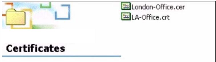
Figure 118 Certificates on Your Computer
3 Double-click the certificate's icon to open the Certificate window. Click the Details tab and scroll down to the Thumbprint Algorithm and Thumbprint fields.
Figure 119 Certificate Details

4 Use a secure method to verify that the certificate owner has the same information in the Thumbprint Algorithm and Thumbprint fields. The secure method may very based on your situation. Possible examples would be over the telephone or through an HTTPS connection.
11.4 Configuration Summary
This section summarizes how to manage certificates on the ZyXEL Device.
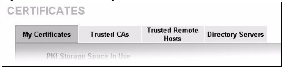
Figure 120 Certificate Configuration Overview
Use the My Certificate screens to generate and export self-signed certificates or certification requests and import the ZyXEL Device's CA-signed certificates.
Use the Trusted CA screens to save the certificates of trusted CAs to the ZyXEL Device. You can also export the certificates to a computer.
Use the Trusted Remote Hosts screens to import self-signed certificates from trusted remote hosts.
Use the Directory Servers screen to configure a list of addresses of directory servers (that contain lists of valid and revoked certificates).
11.5 My Certificates
Click SECURITY > CERTIFICATES > My Certificates to open the My Certificates screen. This is the ZyXEL Device's summary list of certificates and certification requests. Certificates display in black and certification requests display in gray.
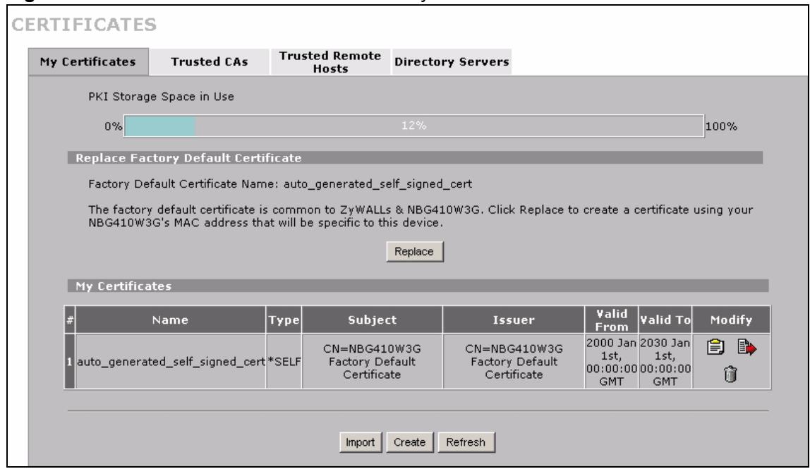
Figure 121 SECURITY > CERTIFICATES > My Certificates
The following table describes the labels in this screen.
Table 51 SECURITY > CERTIFICATES > My Certificates
| LABEL | DESCRIPTION |
| PKI Storage Space in Use | This bar displays the percentage of the ZyXEL Device's PKI storage space that is currently in use. When the storage space is almost full, you should consider deleting expired or unnecessary certificates before adding more certificates. |
| Replace | This button displays when the ZyXEL Device has the factory default certificate. The factory default certificate is common to all ZyXEL Devices that use certificates. ZyXEL recommends that you use this button to replace the factory default certificate with one that uses your ZyXEL Device's MAC address. |
| # | This field displays the certificate index number. The certificates are listed in alphabetical order. |
| Name | This field displays the name used to identify this certificate. It is recommended that you give each certificate a unique name. |
| Type | This field displays what kind of certificate this is. REQ represents a certification request and is not yet a valid certificate. Send a certification request to a certification authority, which then issues a certificate. Use the My Certificate Import screen to import the certificate and replace the request. SELF represents a self-signed certificate. *SELF represents the default self-signed certificate, which the ZyXEL Device uses to sign imported trusted remote host certificates. CERT represents a certificate issued by a certification authority. |
| Subject | This field displays identifying information about the certificate's owner, such as CN (Common Name), OU (Organizational Unit or department), O (Organization or company) and C (Country). It is recommended that each certificate have unique subject information. |
| Issuer | This field displays identifying information about the certificate's issuing certification authority, such as a common name, organizational unit or department, organization or company and country. With self-signed certificates, this is the same information as in the Subject field. |
| Valid From | This field displays the date that the certificate becomes applicable. The text displays in red and includes a Not Yet Valid! message if the certificate has not yet become applicable. |
| Valid To | This field displays the date that the certificate expires. The text displays in red and includes an Expiring! or Expired! message if the certificate is about to expire or has already expired. |
| Modify | Click the details icon to open a screen with an in-depth list of information about the certificate (or certification request).Click the export icon to save the certificate to a computer. For a certification request, click the export icon and then Save in the File Download screen. The Save As screen opens, browse to the location that you want to use and click Save.Click the delete icon to remove the certificate (or certification request). A window displays asking you to confirm that you want to delete the certificate.You cannot delete a certificate that one or more features is configured to use.Do the following to delete a certificate that shows *SELF in the Type field.1. Make sure that no other features, such as HTTPS, SSH are configured to use the *SELF certificate.2. Click the details icon next to another self-signed certificate (see the description on the Create button if you need to create a self-signed certificate).3. Select the Default self-signed certificate which signs the imported remote host certificates check box.4. Click Apply to save the changes and return to the My Certificates screen.5. The certificate that originally showed *SELF displays SELF and you can delete it now.Note that subsequent certificates move up by one when you take this action.The poll now icon displays when the ZyXEL Device generates a certification request successfully but the CA does not issue a certificate and sends a pending notification to the ZyXEL Device. If the icon displays, you can manually click the icon to have the ZyXEL Device query the CA (or RA (Registration Authority)) server for a certificate immediately. Otherwise, the ZyXEL Device checks with the server and updates the status periodically. The poll now icon disappears after the ZyWALL gets a certificate or the request has failed permanently due to being rejected by the CA server. |
| Import | Click Import to open a screen where you can save the certificate that you have enrolled from a certification authority from your computer to the ZyXEL Device. |
| Create | Click Create to go to the screen where you can have the ZyXEL Device generate a certificate or a certification request. |
| Refresh | Click Refresh to display the current validity status of the certificates. |
11.6 My Certificate Details
Click SECURITY > CERTIFICATES > My Certificates to open the My Certificates screen (see Figure 121 on page 198). Click the details icon to open the My Certificate Details screen. You can use this screen to view in-depth certificate information and change the certificate's name.
If it is a self-signed certificate, you can also set the ZyXEL Device to use the certificate to sign the imported trusted remote host certificates.
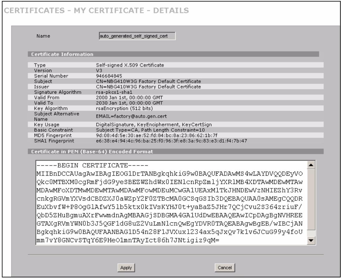
Figure 122 SECURITY > CERTIFICATES > My Certificates > Details
The following table describes the labels in this screen.
Table 52 SECURITY > CERTIFICATES > My Certificates > Details
| LABEL | DESCRIPTION |
| Name | This field displays the identifying name of this certificate. If you want to change the name, type up to 31 characters to identify this certificate. You may use any character (not including spaces). |
| Certificate Information | These read-only fields display detailed information about the certificate. |
| Type | This field displays general information about the certificate. CA-signed means that a Certification Authority signed the certificate. Self-signed means that the certificate's owner signed the certificate (not a certification authority). “X.509” means that this certificate was created and signed according to the ITU-T X.509 recommendation that defines the formats for public-key certificates. |
| Version | This field displays the X.509 version number. |
| Serial Number | This field displays the certificate's identification number given by the certification authority or generated by the ZyXEL Device. |
| Subject | This field displays information that identifies the owner of the certificate, such as Common Name (CN), Organizational Unit (OU), Organization (O) and Country (C). |
| Issuer | This field displays identifying information about the certificate's issuing certification authority, such as Common Name, Organizational Unit, Organization and Country. With self-signed certificates, this is the same as the Subject Name field. |
| Signature Algorithm | This field displays the type of algorithm that was used to sign the certificate. The ZyXEL Device uses rsa-pkcs1-sha1 (RSA public-private key encryption algorithm and the SHA1 hash algorithm). Some certification authorities may use rsa-pkcs1-md5 (RSA public-private key encryption algorithm and the MD5 hash algorithm). |
| Valid From | This field displays the date that the certificate becomes applicable. The text displays in red and includes a Not Yet Valid! message if the certificate has not yet become applicable. |
| Valid To | This field displays the date that the certificate expires. The text displays in red and includes an Expiring! or Expired! message if the certificate is about to expire or has already expired. |
| Key Algorithm | This field displays the type of algorithm that was used to generate the certificate's key pair (the ZyXEL Device uses RSA encryption) and the length of the key set in bits (1024 bits for example). |
| Subject Alternative Name | This field displays the certificate owner's IP address (IP), domain name (DNS) or e-mail address (EMAIL). |
| Key Usage | This field displays for what functions the certificate's key can be used. For example, "DigitalSignature" means that the key can be used to sign certificates and "KeyEncipherment" means that the key can be used to encrypt text. |
| Basic Constraint | This field displays general information about the certificate. For example, Subject Type=CA means that this is a certification authority's certificate and "Path Length Constraint=1" means that there can only be one certification authority in the certificate's path. |
| MD5 Fingerprint | This is the certificate's message digest that the ZyXEL Device calculated using the MD5 algorithm. |
| SHA1 Fingerprint | This is the certificate's message digest that the ZyXEL Device calculated using the SHA1 algorithm. |
| Certificate in PEM (Base-64) Encoded Format | This read-only text box displays the certificate or certification request in Privacy Enhanced Mail (PEM) format. PEM uses 64 ASCII characters to convert the binary certificate into a printable form. You can copy and paste a certification request into a certification authority's web page, an e-mail that you send to the certification authority or a text editor and save the file on a management computer for later manual enrollment. You can copy and paste a certificate into an e-mail to send to friends or colleagues or you can copy and paste a certificate into a text editor and save the file on a management computer for later distribution (via floppy disk for example). |
| Apply | Click Apply to save your changes back to the ZyXEL Device. You can only change the name, except in the case of a self-signed certificate, which you can also set to be the default self-signed certificate that signs the imported trusted remote host certificates. |
| Cancel | Click Cancel to quit and return to the My Certificates screen. |
11.7 My Certificate Export
Click SECURITY > CERTIFICATES > My Certificates and then a certificate's export icon to open the My Certificate Export screen. Follow the instructions in this screen to choose the file format to use for saving the certificate from the ZyXEL Device to a computer.
11.7.1 Certificate File Export Formats
You can export a certificate in one of these file formats:
- Binary X.509: This is an ITU-T recommendation that defines the formats for X.509 certificates.
- Binary PKCS#12: This is a format for transferring public key and private key certificates. The private key in a PKCS #12 file is within a password-encrypted envelope. The file's password is not connected to your certificate's public or private passwords. Exporting a PKCS #12 file creates this and you must provide it to decrypt the contents when you import the file into the ZyXEL Device.
Figure 123 SECURITY > CERTIFICATES > My Certificates > Export
CERTIFICATES - MY CERTIFICATE - EXPORT
Export
Please specify whether to export the certificate along with the corresponding private key.
Export the certificate in binary X.509 format.
Export the certificate along with the corresponding private key in PKCS#12 format. For security concern, you may provide a password to protect the private key.
Password
Retype to Confirm
Apply
Cancel
The following table describes the labels in this screen.
Table 53 SECURITY > CERTIFICATES > My Certificates > Export
| LABEL | DESCRIPTION |
| Export the certificate in binary X.509 format. | Binary X.509 is an ITU-T recommendation that defines the formats for X.509 certificates. |
| Export the certificate along with the corresponding private key in PKCS#12 format. | PKCS#12 is a format for transferring public key and private key certificates. You can also password-encrypt the private key in the PKCS #12 file. The file's password is not connected to your certificate's public or private passwords. |
| Password | Type the file's password to use for encrypting the private key. The password is optional, although you must specify one if you want to be able to import the PKCS#12 format certificate into Netscape version 7.2. |
| Retype to confirm | Type the password to make sure that you have entered it correctly. |
| Apply | Click Apply and then Save in the File Download screen. The Save As screen opens, browse to the location that you want to use and click Save. |
| Cancel | Click Cancel to quit and return to the My Certificates screen. |
11.8 My Certificate Import
Click SECURITY > CERTIFICATES > My Certificates and then Import to open the My Certificate Import screen. Follow the instructions in this screen to save an existing certificate from a computer to the ZyXEL Device.

You can only import a certificate that matches a corresponding certification request that was generated by the ZyXEL Device (the certification request contains the private key). The certificate you import replaces the corresponding request in the My Certificates screen.
One exception is that you can import a PKCS#12 format certificate without a corresponding certification request since the certificate includes the private key.

You must remove any spaces from the certificate's filename before you can import it.
11.8.1 Certificate File Formats
The certification authority certificate that you want to import has to be in one of these file formats:
- Binary X.509: This is an ITU-T recommendation that defines the formats for X.509 certificates.
- PEM (Base-64) encoded X.509: This Privacy Enhanced Mail format uses 64 ASCII characters to convert a binary X.509 certificate into a printable form.
- Binary PKCS#7: This is a standard that defines the general syntax for data (including digital signatures) that may be encrypted. The ZyXEL Device currently allows the importation of a PKS#7 file that contains a single certificate.
- PEM (Base-64) encoded PKCS#7: This Privacy Enhanced Mail (PEM) format uses 64 ASCII characters to convert a binary PKCS#7 certificate into a printable form.
- Binary PKCS#12: This is a format for transferring public key and private key certificates. The private key in a PKCS #12 file is within a password-encrypted envelope. The file's password is not connected to your certificate's public or private passwords. Exporting a PKCS #12 file creates this and you must provide it to decrypt the contents when you import the file into the ZyXEL Device.

Be careful to not convert a binary file to text during the transfer process. It is easy for this to occur since many programs use text files by default.
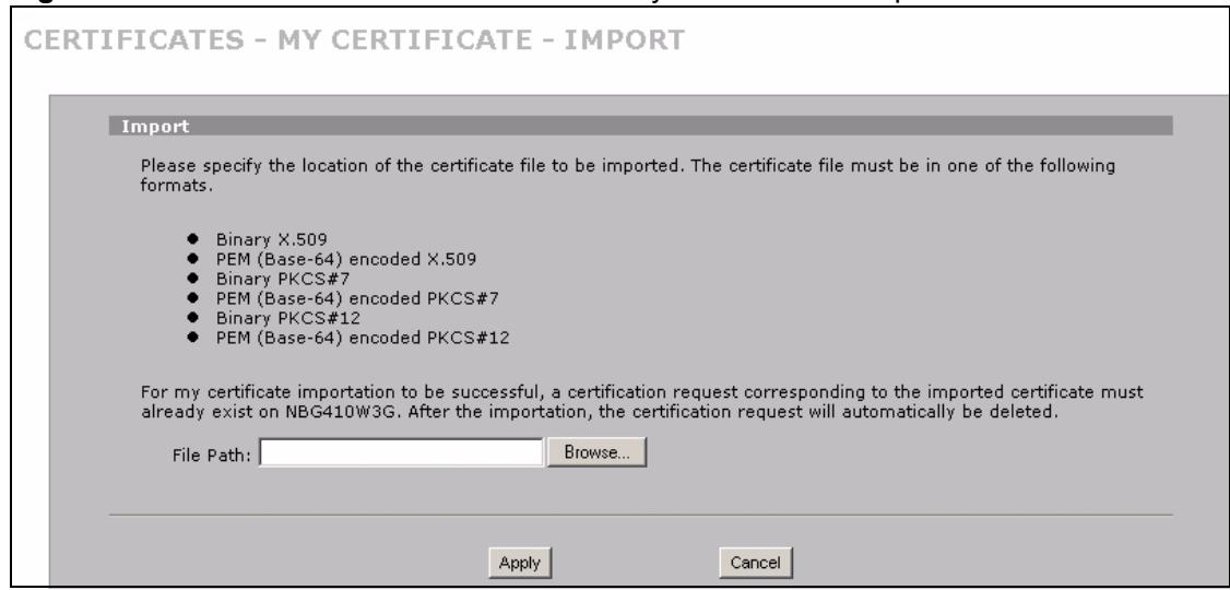
Figure 124 SECURITY > CERTIFICATES > My Certificates > Import
The following table describes the labels in this screen.
Table 54 SECURITY > CERTIFICATES > My Certificates > Import
| LABEL | DESCRIPTION |
| File Path | Type in the location of the file you want to upload in this field or click Browse to find it. |
| Browse | Click Browse to find the certificate file you want to upload. |
| Apply | Click Apply to save the certificate on the ZyXEL Device. |
| Cancel | Click Cancel to quit and return to the My Certificates screen. |
When you import a binary PKCS#12 format certificate, another screen displays for you to enter the password.
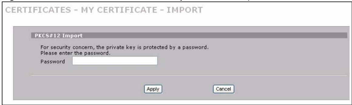
Figure 125 SECURITY > CERTIFICATES > My Certificates > Import: PKCS#12
The following table describes the labels in this screen.
Table 55 SECURITY > CERTIFICATES > My Certificates > Import: PKCS#12
| LABEL | DESCRIPTION |
| Password | Type the file's password that was created when the PKCS #12 file was exported. |
| Apply | Click Apply to save the certificate on the ZyXEL Device. |
| Cancel | Click Cancel to quit and return to the My Certificates screen. |
11.9 My Certificate Create
Click SECURITY > CERTIFICATES > My Certificates > Create to open the My Certificate Create screen. Use this screen to have the ZyXEL Device create a self-signed certificate, enroll a certificate with a certification authority or generate a certification request.
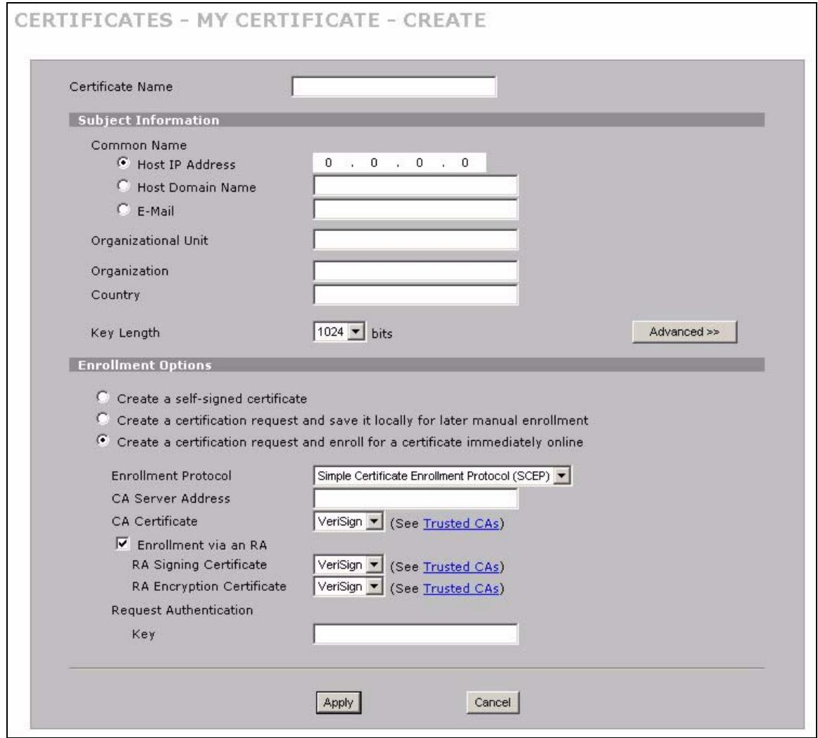
Figure 126 SECURITY > CERTIFICATES > My Certificates > Create (Basic)
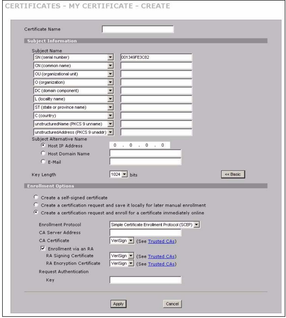
Figure 127 SECURITY > CERTIFICATES > My Certificates > Create (Advanced)
The following table describes the labels in this screen.
Table 56 SECURITY > CERTIFICATES > My Certificates > Create
| LABEL | DESCRIPTION |
| Certificate Name | Type up to 31 ASCII characters (not including spaces) to identify this certificate. |
| Subject Information | Use these fields to record information that identifies the owner of the certificate. You do not have to fill in every field, but the Common Name is mandatory if you click << Basic. The certification authority may add fields (such as a serial number) to the subject information when it issues a certificate. It is recommended that each certificate have unique subject information. |
| The fields below display when you click << Basic. | |
| Common Name | Select a radio button to identify the certificate's owner by IP address, domain name or e-mail address. Type the IP address (in dotted decimal notation), domain name or e-mail address in the field provided. The domain name or e-mail address can be up to 31 ASCII characters. The domain name or e-mail address is for identification purposes only and can be any string. |
| Organizational Unit | Type up to 63 characters to identify the organizational unit or department to which the certificate owner belongs. You may use any character, including spaces, but the ZyXEL Device drops trailing spaces. |
| Organization | Type up to 63 characters to identify the company or group to which the certificate owner belongs. You may use any character, including spaces, but the ZyXEL Device drops trailing spaces. |
| Country | Type up to 63 characters to identify the nation where the certificate owner is located. You may use any character, including spaces, but the ZyXEL Device drops trailing spaces. |
| The fields below display when you click Advanced >>. | |
| Subject Name | You must configure at least one of these fields. Select an item from the drop-down list box and enter the corresponding information in the field to the right. SN (serial number) - select this and enter the certificate's identification number, such as the ZyXEL Device's MAC address. You can use up to 63 characters. CN (common name) - select this and enter a name to identify the owner of the certificate. You can use up to 63 characters. OU (organizational unit) - select this and enter a unit within the organization to identify the owner of the certificate. You can use up to 63 characters. O (organization) - select this and enter an organization to identify the owner of the certificate. You can use up to 63 characters. DC (domain component) - select this and enter the domain component of a domain to identify the owner of the certificate. For example, if the domain is zyxel.com, the domain component is "zyxel" or "com". You can use up to 63 characters. L (locality name) - select this and enter the place where the owner of the certificate resides, such as a city or county. You can use up to 63 characters. ST (state or province name) - select this and enter the state or province in which the owner of the certificate resides. You can use up to 63 characters. C (country) - select this and enter the name of the country at which the owner of the certificate resides. You can use up to 63 characters. unstructuredName (PKCS 9 unname) - select this and enter the name of the owner of the certificate as an unstructured ASCII string. You can use up to 63 characters. Check with the certificate's issuing certification authority for their interpretation in this field if you select to apply to a certification authority for a certificate. unstructuredAddress (PKCS 9 unaddr) - select this and enter the address of the owner of the certificate as an unstructured ASCII string. You can use up to 63 characters. Check with the certificate's issuing certification authority for their interpretation in this field if you select to apply to a certification authority for a certificate. MAILTO (PKCS 9 email address) - select this and enter the email address of the owner of the certificate. You can use up to 63 characters. Check with the certificate's issuing certification authority for their interpretation in this field if you select to apply to a certification authority for a certificate. |
| Subject Alternative Name | Select a radio button to identify the certificate's owner by IP address, domain name or e-mail address. Type the IP address (in dotted decimal notation), domain name or e-mail address in the field provided. The domain name or e-mail address can be up to 31 ASCII characters. The domain name or e-mail address is for identification purposes only and can be any string. |
| Key Length | Select a number from the drop-down list box to determine how many bits the key should use (512 to 2048). The longer the key, the more secure it is. A longer key also uses more PKI storage space. |
| << Basic/Advanced >> | Click << Basic to configure basic subject information. Click Advanced >> to configure more subject information for a certificate. |
| Enrollment Options | These radio buttons deal with how and when the certificate is to be generated. |
| Create a self-signed certificate | Select Create a self-signed certificate to have the ZyXEL Device generate the certificate and act as the Certification Authority (CA) itself. This way you do not need to apply to a certification authority for certificates. |
| Create a certification request and save it locally for later manual enrollment | Select Create a certification request and save it locally for later manual enrollment to have the ZyXEL Device generate and store a request for a certificate. Use the My Certificate Details screen to view the certification request and copy it to send to the certification authority. Copy the certification request from the My Certificate Details screen (see Section 11.6 on page 200) and then send it to the certification authority. |
| Create a certification request and enroll for a certificate immediately online | Select Create a certification request and enroll for a certificate immediately online to have the ZyXEL Device generate a request for a certificate and apply to a certification authority for a certificate. You must have the certification authority's certificate already imported in the Trusted CAs screen. When you select this option, you must select the certification authority's enrollment protocol and the certification authority's certificate from the drop-down list boxes and enter the certification authority's server address. You also need to fill in the Reference Number and Key if the certification authority requires them. |
| Enrollment Protocol | Select the certification authority's enrollment protocol from the drop-down list box. Simple Certificate Enrollment Protocol (SCEP) is a TCP-based enrollment protocol that was developed by VeriSign and Cisco. Certificate Management Protocol (CMP) is a TCP-based enrollment protocol that was developed by the Public Key Infrastructure X.509 working group of the Internet Engineering Task Force (IETF) and is specified in RFC 2510. |
| CA Server Address | Enter the IP address (or URL) of the certification authority server. |
| CA Certificate | Select the certification authority's certificate from the CA Certificate drop-down list box. You must have the certification authority's certificate already imported in the Trusted CAs screen. Click Trusted CAs to go to the Trusted CAs screen where you can view (and manage) the ZyXEL Device's list of certificates of trusted certification authorities. |
| Enrollment via an RA | If you select Create a certification request and enroll for a certificate immediately online, you can select this option to apply for a certificate through a RA (Registration Authority). The RA is an intermediary authorized by a CA to verify each subscriber's identity and forward the requests to the CA. After the CA signs and issues the certificates, the RA distributes the certificates to the subscribers. |
| RA Signing Certificate | If you select Enrollment via an RA, select the CA's RA signing certificate from the drop-down list box. You must have the certificate already imported in the Trusted CAs screen. Click Trusted CAs to go to the Trusted CAs screen where you can view (and manage) the ZyXEL Device's list of certificates of trusted certification authorities. |
| RA Encryption Certificate | If you select Enrollment via an RA, select the CA's RA encryption certificate from the drop-down list box. You must have the certificate already imported in the Trusted CAs screen. Click Trusted CAs to go to the Trusted CAs screen where you can view (and manage) the ZyXEL Device's list of certificates of trusted certification authorities. |
| Request Authentication | When you select Create a certification request and enroll for a certificate immediately online, the certification authority may want you to include a reference number and key to identify you when you send a certification request. Fill in both the Reference Number and the Key fields if your certification authority uses CMP enrollment protocol. Just fill in the Key field if your certification authority uses the SCEP enrollment protocol. |
| Reference Number | Enter the reference number that the certification authority gave you. You can use up to 31 ASCII printable characters. Spaces are allowed. |
| Key | Type the key that the certification authority gave you. You can use up to 31 ASCII printable characters. Spaces are allowed. |
| Apply | Click Apply to begin certificate or certification request generation. |
| Cancel | Click Cancel to quit and return to the My Certificates screen. |
After you click Apply in the My Certificate Create screen, you see a screen that tells you the ZyXEL Device is generating the self-signed certificate or certification request.
After the ZyXEL Device successfully enrolls a certificate or generates a certification request or a self-signed certificate, you see a screen with a Return button that takes you back to the My Certificates screen.
If you configured the My Certificate Create screen to have the ZyXEL Device enroll a certificate and the certificate enrollment is not successful, you see a screen with a Return button that takes you back to the My Certificate Create screen. Click Return and check your information in the My Certificate Create screen. Make sure that the certification authority information is correct and that your Internet connection is working properly if you want the ZyXEL Device to enroll a certificate online.
11.10 Trusted CAs
Click SECURITY > CERTIFICATES > Trusted CAs to open the Trusted CAs screen. This screen displays a summary list of certificates of the certification authorities that you have set the ZyXEL Device to accept as trusted. The ZyXEL Device accepts any valid certificate signed by a certification authority on this list as being trustworthy; thus you do not need to import any certificate that is signed by one of these certification authorities.
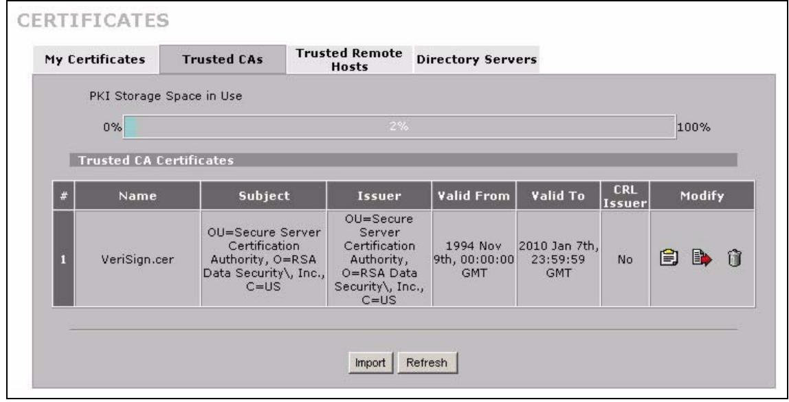
Figure 128 SECURITY > CERTIFICATES > Trusted CAs
The following table describes the labels in this screen.
Table 57 SECURITY > CERTIFICATES > Trusted CAs
| LABEL | DESCRIPTION |
| PKI Storage Space in Use | This bar displays the percentage of the ZyXEL Device's PKI storage space that is currently in use. When the storage space is almost full, you should consider deleting expired or unnecessary certificates before adding more certificates. |
| # | This field displays the certificate index number. The certificates are listed in alphabetical order. |
| Name | This field displays the name used to identify this certificate. |
| Subject | This field displays identifying information about the certificate's owner, such as CN (Common Name), OU (Organizational Unit or department), O (Organization or company) and C (Country). It is recommended that each certificate have unique subject information. |
| Issuer | This field displays identifying information about the certificate's issuing certification authority, such as a common name, organizational unit or department, organization or company and country. With self-signed certificates, this is the same information as in the Subject field. |
| Valid From | This field displays the date that the certificate becomes applicable. The text displays in red and includes a Not Yet Valid! message if the certificate has not yet become applicable. |
| Valid To | This field displays the date that the certificate expires. The text displays in red and includes an Expiring! or Expired! message if the certificate is about to expire or has already expired. |
| CRL Issuer | This field displays Yes if the certification authority issues CRL (Certificate Revocation Lists) for the certificates that it has issued and you have selected the-Check incoming certificates issued by this CA against a CRL check box in the certificate's details screen to have the ZyXEL Device check the CRL before trusting any certificates issued by the certification authority. Otherwise the field displays No. |
| Modify | Click the details icon to open a screen with an in-depth list of information about the certificate.Use the export icon to save the certificate to a computer. Click the icon and then Save in the File Download screen. The Save As screen opens, browse to the location that you want to use and click Save.Click the delete icon to remove the certificate. A window displays asking you to confirm that you want to delete the certificates. Note that subsequent certificates move up by one when you take this action. |
| Import | Click Import to open a screen where you can save the certificate of a certification authority that you trust, from your computer to the ZyXEL Device. |
| Refresh | Click this button to display the current validity status of the certificates. |
11.11 Trusted CA Details
Click SECURITY > CERTIFICATES > Trusted CAs to open the Trusted CAs screen. Click the details icon to open the Trusted CA Details screen. Use this screen to view in-depth information about the certification authority's certificate, change the certificate's name and set whether or not you want the ZyXEL Device to check a certification authority's list of revoked certificates before trusting a certificate issued by the certification authority.
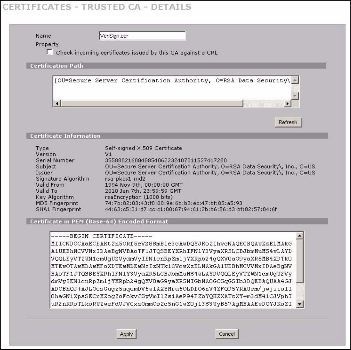
Figure 129 SECURITY > CERTIFICATES > Trusted CAs > Details
The following table describes the labels in this screen.
Table 58 SECURITY > CERTIFICATES > Trusted CAs > Details
| LABEL | DESCRIPTION |
| Name | This field displays the identifying name of this certificate. If you want to change the name, type up to 31 characters to identify this key certificate. You may use any character (not including spaces). |
| Property Check incoming certificates issued by this CA against a CRL | Select this check box to have the ZyXEL Device check incoming certificates that are issued by this certification authority against a Certificate Revocation List (CRL).Clear this check box to have the ZyXEL Device not check incoming certificates that are issued by this certification authority against a Certificate Revocation List (CRL). |
| Certification Path | Click the Refresh button to have this read-only text box display the end entity's certificate and a list of certification authority certificates that shows the hierarchy of certification authorities that validate the end entity's certificate. If the issuing certification authority is one that you have imported as a trusted certification authority, it may be the only certification authority in the list (along with the end entity's own certificate). The ZyXEL Device does not trust the end entity's certificate and displays "Not trusted" in this field if any certificate on the path has expired or been revoked. |
| Refresh | Click Refresh to display the certification path. |
| Certificate Information | These read-only fields display detailed information about the certificate. |
| Type | This field displays general information about the certificate. CA-signed means that a Certification Authority signed the certificate. Self-signed means that the certificate's owner signed the certificate (not a certification authority). X.509 means that this certificate was created and signed according to the ITU-T X.509 recommendation that defines the formats for public-key certificates. |
| Version | This field displays the X.509 version number. |
| Serial Number | This field displays the certificate's identification number given by the certification authority. |
| Subject | This field displays information that identifies the owner of the certificate, such as Common Name (CN), Organizational Unit (OU), Organization (O) and Country (C). |
| Issuer | This field displays identifying information about the certificate's issuing certification authority, such as Common Name, Organizational Unit, Organization and Country. With self-signed certificates, this is the same information as in the Subject Name field. |
| Signature Algorithm | This field displays the type of algorithm that was used to sign the certificate. Some certification authorities use rsa-pkcs1-sha1 (RSA public-private key encryption algorithm and the SHA1 hash algorithm). Other certification authorities may use rsa-pkcs1-md5 (RSA public-private key encryption algorithm and the MD5 hash algorithm). |
| Valid From | This field displays the date that the certificate becomes applicable. The text displays in red and includes a Not Yet Valid! message if the certificate has not yet become applicable. |
| Valid To | This field displays the date that the certificate expires. The text displays in red and includes an Expiring! or Expired! message if the certificate is about to expire or has already expired. |
| Key Algorithm | This field displays the type of algorithm that was used to generate the certificate's key pair (the ZyXEL Device uses RSA encryption) and the length of the key set in bits (1024 bits for example). |
| Subject Alternative Name | This field displays the certificate's owner's IP address (IP), domain name (DNS) or e-mail address (EMAIL). |
| Key Usage | This field displays for what functions the certificate's key can be used. For example, "DigitalSignature" means that the key can be used to sign certificates and "KeyEncipherment" means that the key can be used to encrypt text. |
| Basic Constraint | This field displays general information about the certificate. For example, Subject Type=CA means that this is a certification authority's certificate and "Path Length Constraint=1" means that there can only be one certification authority in the certificate's path. |
| CRL Distribution Points | This field displays how many directory servers with Lists of revoked certificates the issuing certification authority of this certificate makes available. This field also displays the domain names or IP addresses of the servers. |
| MD5 Fingerprint | This is the certificate's message digest that the ZyXEL Device calculated using the MD5 algorithm. You can use this value to verify with the certification authority (over the phone for example) that this is actually their certificate. |
| SHA1 Fingerprint | This is the certificate's message digest that the ZyXEL Device calculated using the SHA1 algorithm. You can use this value to verify with the certification authority (over the phone for example) that this is actually their certificate. |
| Certificate in PEM (Base-64) Encoded Format | This read-only text box displays the certificate or certification request in Privacy Enhanced Mail (PEM) format. PEM uses 64 ASCII characters to convert the binary certificate into a printable form. You can copy and paste the certificate into an e-mail to send to friends or colleagues or you can copy and paste the certificate into a text editor and save the file on a management computer for later distribution (via floppy disk for example). |
| Apply | Click Apply to save your changes back to the ZyXEL Device. You can only change the name and/or set whether or not you want the ZyXEL Device to check the CRL that the certification authority issues before trusting a certificate issued by the certification authority. |
| Cancel | Click Cancel to quit and return to the Trusted CAs screen. |
11.12 Trusted CA Import
Click SECURITY > CERTIFICATES > Trusted CAs to open the Trusted CAs screen and then click Import to open the Trusted CA Import screen. Follow the instructions in this screen to save a trusted certification authority's certificate from a computer to the ZyXEL Device. The ZyXEL Device trusts any valid certificate signed by any of the imported trusted CA certificates.

You must remove any spaces from the certificate's filename before you can import the certificate.
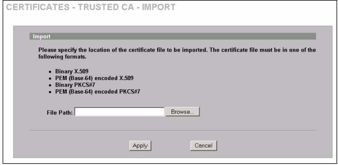
Figure 130 SECURITY > CERTIFICATES > Trusted CAs > Import
The following table describes the labels in this screen.
Table 59 SECURITY > CERTIFICATES > Trusted CAs Import
| LABEL | DESCRIPTION |
| File Path | Type in the location of the file you want to upload in this field or click Browse to find it. |
| Browse | Click Browse to find the certificate file you want to upload. |
| Apply | Click Apply to save the certificate on the ZyXEL Device. |
| Cancel | Click Cancel to quit and return to the Trusted CAs screen. |
11.13 Trusted Remote Hosts
Click SECURITY > CERTIFICATES > Trusted Remote Hosts to open the Trusted Remote Hosts screen. This screen displays a list of the certificates of peers that you trust but which are not signed by one of the certification authorities on the Trusted CAs screen.
You do not need to add any certificate that is signed by one of the certification authorities on the Trusted CAs screen since the ZyXEL Device automatically accepts any valid certificate signed by a trusted certification authority as being trustworthy.

Figure 131 SECURITY > CERTIFICATES > Trusted Remote Hosts
The following table describes the labels in this screen.
Table 60 SECURITY > CERTIFICATES > Trusted Remote Hosts
| LABEL | DESCRIPTION |
| PKI Storage Space in Use | This bar displays the percentage of the ZyXEL Device's PKI storage space that is currently in use. When the storage space is almost full, you should consider deleting expired or unnecessary certificates before adding more certificates. |
| Issuer (My Default Self-signed Certificate) | This field displays identifying information about the default self-signed certificate on the ZyXEL Device that the ZyXEL Device uses to sign the trusted remote host certificates. |
| # | This field displays the certificate index number. The certificates are listed in alphabetical order. |
| Name | This field displays the name used to identify this certificate. |
| Subject | This field displays identifying information about the certificate's owner, such as CN (Common Name), OU (Organizational Unit or department), O (Organization or company) and C (Country). It is recommended that each certificate have unique subject information. |
| Valid From | This field displays the date that the certificate becomes applicable. The text displays in red and includes a Not Yet Valid! message if the certificate has not yet become applicable. |
| Valid To | This field displays the date that the certificate expires. The text displays in red and includes an Expiring! or Expired! message if the certificate is about to expire or has already expired. |
| Modify | Click the details icon to open a screen with an in-depth list of information about the certificate.Use the export icon to save the certificate to a computer. Click the icon and then Save in the File Download screen. The Save As screen opens, browse to the location that you want to use and click Save.Click the delete icon to remove the certificate. A window displays asking you to confirm that you want to delete the certificate. Note that subsequent certificates move up by one when you take this action. |
| Import | Click Import to open a screen where you can save the certificate of a remote host (which you trust) from your computer to the ZyXEL Device. |
| Refresh | Click this button to display the current validity status of the certificates. |
11.14 Trusted Remote Hosts Import
Click SECURITY > CERTIFICATES > Trusted Remote Hosts to open the Trusted Remote Hosts screen and then click Import to open the Trusted Remote Host Import screen.
You may have peers with certificates that you want to trust, but the certificates were not signed by one of the certification authorities on the Trusted CAs screen. Follow the instructions in this screen to save a peer's certificates from a computer to the ZyXEL Device.
You do not need to add any certificate that is signed by one of the certification authorities on the Trusted CAs screen since the ZyXEL Device automatically accepts any valid certificate signed by a trusted certification authority as being trustworthy.

The trusted remote host certificate must be a self-signed certificate; and you must remove any spaces from its filename before you can import it.
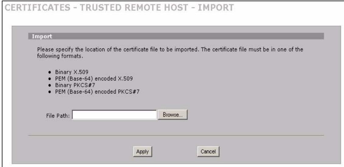
Figure 132 SECURITY > CERTIFICATES > Trusted Remote Hosts > Import
The following table describes the labels in this screen.
Table 61 SECURITY > CERTIFICATES > Trusted Remote Hosts > Import
| LABEL | DESCRIPTION |
| File Path | Type in the location of the file you want to upload in this field or click Browse to find it. |
| Browse | Click Browse to find the certificate file you want to upload. |
| Apply | Click Apply to save the certificate on the ZyXEL Device. |
| Cancel | Click Cancel to quit and return to the Trusted Remote Hosts screen. |
11.15 Trusted Remote Host Certificate Details
Click SECURITY > CERTIFICATES > Trusted Remote Hosts to open the Trusted Remote Hosts screen. Click the details icon to open the Trusted Remote Host Details screen. You can use this screen to view in-depth information about the trusted remote host's certificate and/or change the certificate's name.
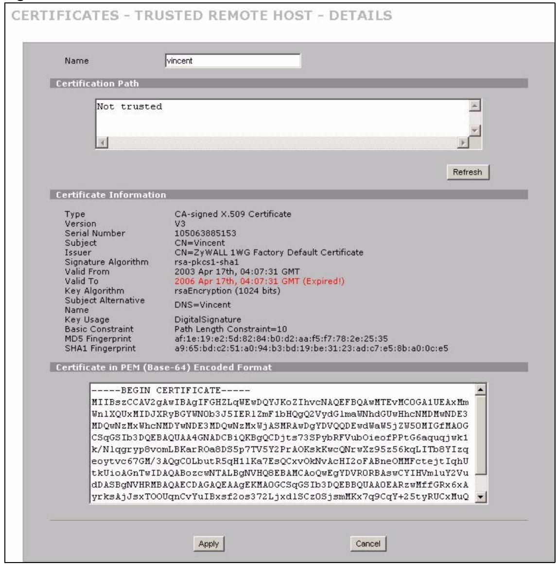
Figure 133 SECURITY > CERTIFICATES > Trusted Remote Hosts > Details
The following table describes the labels in this screen.
Table 62 SECURITY > CERTIFICATES > Trusted Remote Hosts > Details
| LABEL | DESCRIPTION |
| Name | This field displays the identifying name of this certificate. If you want to change the name, type up to 31 characters to identify this key certificate. You may use any character (not including spaces). |
| Certification Path | Click the Refresh button to have this read-only text box display the end entity's own certificate and a list of certification authority certificates in the hierarchy of certification authorities that validate a certificate's issuing certification authority. For a trusted host, the list consists of the end entity's own certificate and the default self-signed certificate that the ZyXEL Device uses to sign remote host certificates. |
| Refresh | Click Refresh to display the certification path. |
| Certificate Information | These read-only fields display detailed information about the certificate. |
| Type | This field displays general information about the certificate. With trusted remote host certificates, this field always displays CA-signed. The ZyXEL Device is the Certification Authority that signed the certificate. X.509 means that this certificate was created and signed according to the ITU-T X.509 recommendation that defines the formats for public-key certificates. |
| Version | This field displays the X.509 version number. |
| Serial Number | This field displays the certificate's identification number given by the device that created the certificate. |
| Subject | This field displays information that identifies the owner of the certificate, such as Common Name (CN), Organizational Unit (OU), Organization (O) and Country (C). |
| Issuer | This field displays identifying information about the default self-signed certificate on the ZyXEL Device that the ZyXEL Device uses to sign the trusted remote host certificates. |
| Signature Algorithm | This field displays the type of algorithm that the ZyXEL Device used to sign the certificate, which is rsa-pkcs1-sha1 (RSA public-private key encryption algorithm and the SHA1 hash algorithm). |
| Valid From | This field displays the date that the certificate becomes applicable. The text displays in red and includes a Not Yet Valid! message if the certificate has not yet become applicable. |
| Valid To | This field displays the date that the certificate expires. The text displays in red and includes an Expiring! or Expired! message if the certificate is about to expire or has already expired. |
| Key Algorithm | This field displays the type of algorithm that was used to generate the certificate's key pair (the ZyXEL Device uses RSA encryption) and the length of the key set in bits (1024 bits for example). |
| Subject Alternative Name | This field displays the certificate's owner's IP address (IP), domain name (DNS) or e-mail address (EMAIL). |
| Key Usage | This field displays for what functions the certificate's key can be used. For example, "DigitalSignature" means that the key can be used to sign certificates and "KeyEncipherment" means that the key can be used to encrypt text. |
| Basic Constraint | This field displays general information about the certificate. For example, Subject Type=CA means that this is a certification authority's certificate and "Path Length Constraint=1" means that there can only be one certification authority in the certificate's path. |
| MD5 Fingerprint | This is the certificate's message digest that the ZyXEL Device calculated using the MD5 algorithm. The ZyXEL Device uses one of its own self-signed certificates to sign the imported trusted remote host certificates. This changes the fingerprint value displayed here (so it does not match the original). See Section 11.3 on page 196 for how to verify a remote host's certificate before you import it into the ZyXEL Device. |
| SHA1 Fingerprint | This is the certificate's message digest that the ZyXEL Device calculated using the SHA1 algorithm. The ZyXEL Device uses one of its own self-signed certificates to sign the imported trusted remote host certificates. This changes the fingerprint value displayed here (so it does not match the original). See Section 11.3 on page 196 for how to verify a remote host's certificate before you import it into the ZyXEL Device. |
| Certificate in PEM (Base-64) Encoded Format | This read-only text box displays the certificate or certification request in Privacy Enhanced Mail (PEM) format. PEM uses 64 ASCII characters to convert the binary certificate into a printable form. You can copy and paste the certificate into an e-mail to send to friends or colleagues or you can copy and paste the certificate into a text editor and save the file on a management computer for later distribution (via floppy disk for example). |
| Apply | Click Apply to save your changes back to the ZyXEL Device. You can only change the name of the certificate. |
| Cancel | Click Cancel to quit configuring this screen and return to the Trusted Remote Hosts screen. |
11.16 Directory Servers
Click SECURITY > CERTIFICATES > Directory Servers to open the Directory Servers screen. This screen displays a summary list of directory servers (that contain lists of valid and revoked certificates) that have been saved into the ZyXEL Device. If you decide to have the ZyXEL Device check incoming certificates against the issuing certification authority's list of revoked certificates, the ZyXEL Device first checks the server(s) listed in the CRL
Distribution Points field of the incoming certificate. If the certificate does not list a server or the listed server is not available, the ZyXEL Device checks the servers listed here.
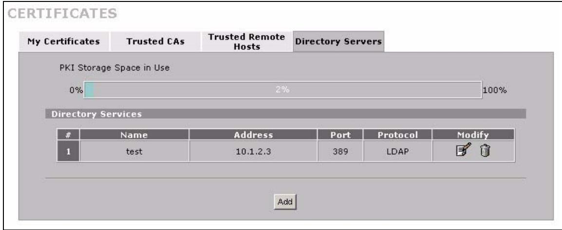
Figure 134 SECURITY > CERTIFICATES > Directory Servers
The following table describes the labels in this screen.
Table 63 SECURITY > CERTIFICATES > Directory Servers
| LABEL | DESCRIPTION |
| PKI Storage Space in Use | This bar displays the percentage of the ZyXEL Device's PKI storage space that is currently in use. When the storage space is almost full, you should consider deleting expired or unnecessary certificates before adding more certificates. |
| # | The index number of the directory server. The servers are listed in alphabetical order. |
| Name | This field displays the name used to identify this directory server. |
| Address | This field displays the IP address or domain name of the directory server. |
| Port | This field displays the port number that the directory server uses. |
| Protocol | This field displays the protocol that the directory server uses. |
| Modify | Click the details icon to open a screen where you can change the information about the directory server. Click the delete icon to remove the directory server entry. A window displays asking you to confirm that you want to delete the directory server. Note that subsequent certificates move up by one when you take this action. |
| Add | Click Add to open a screen where you can configure information about a directory server so that the ZyXEL Device can access it. |
11.17 Directory Server Add or Edit
Click SECURITY > CERTIFICATES > Directory Servers to open the Directory Servers screen. Click Add (or the details icon) to open the Directory Server Add screen. Use this screen to configure information about a directory server that the ZyXEL Device can access.
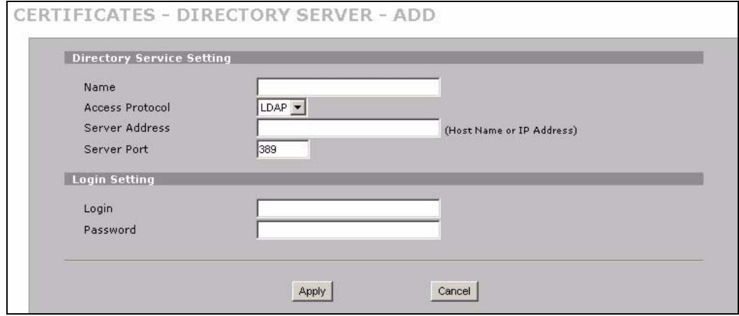
Figure 135 SECURITY > CERTIFICATES > Directory Server > Add
The following table describes the labels in this screen.
Table 64 SECURITY > CERTIFICATES > Directory Server > Add
| LABEL | DESCRIPTION |
| Directory Service Setting | |
| Name | Type up to 31 ASCII characters (spaces are not permitted) to identify this directory server. |
Table 64 SECURITY > CERTIFICATES > Directory Server > Add
| LABEL | DESCRIPTION |
| Access Protocol | Use the drop-down list box to select the access protocol used by the directory server. LDAP (Lightweight Directory Access Protocol) is a protocol over TCP that specifies how clients access directories of certificates and lists of revoked certificates. A |
| Server Address | Type the IP address (in dotted decimal notation) or the domain name of the directory server. |
| Server Port | This field displays the default server port number of the protocol that you select in the Access Protocol field. You may change the server port number if needed, however you must use the same server port number that the directory server uses. 389 is the default server port number for LDAP. |
| Login Setting | |
| Login | The ZyXEL Device may need to authenticate itself in order to assess the directory server. Type the login name (up to 31 ASCII characters) from the entity maintaining the directory server (usually a certification authority). |
| Password | Type the password (up to 31 ASCII characters) from the entity maintaining the directory server (usually a certification authority). |
| Apply | Click Apply to save your changes back to the ZyXEL Device. |
| Cancel | Click Cancel to quit configuring this screen and return to the Directory Servers screen. |
A. At the time of writing, LDAP is the only choice of directory server access protocol.
PART V
Advanced
Network Address Translation (NAT) (225)
Static Route (243)
DNS (247)
Remote Management (259)
UPnP (281)
Custom Application (291)
ALG Screen (293)
Network Address Translation (NAT)
This chapter discusses how to configure NAT on the ZyXEL Device.
12.1 NAT Overview
NAT (Network Address Translation - NAT, RFC 1631) is the translation of the IP address of a host in a packet. For example, the source address of an outgoing packet, used within one network is changed to a different IP address known within another network.
12.1.1 NAT Definitions
Inside/outside denotes where a host is located relative to the ZyXEL Device. For example, the computers of your subscribers are the inside hosts, while the web servers on the Internet are the outside hosts.
Global/local denotes the IP address of a host in a packet as the packet traverses a router. For example, the local address refers to the IP address of a host when the packet is in the local network, while the global address refers to the IP address of the host when the same packet is traveling in the WAN side.
Note that inside/outside refers to the location of a host, while global/local refers to the IP address of a host used in a packet. Thus, an inside local address (ILA) is the IP address of an inside host in a packet when the packet is still in the local network, while an inside global address (IGA) is the IP address of the same inside host when the packet is on the WAN side. The following table summarizes this information.
Table 65 NAT Definitions
| TERM | DESCRIPTION |
| Inside | This refers to the host on the LAN. |
| Outside | This refers to the host on the WAN. |
| Local | This refers to the packet address (source or destination) as the packet travels on the LAN. |
| Global | This refers to the packet address (source or destination) as the packet travels on the WAN. |

NAT never changes the IP address (either local or global) of an outside host.
12.1.2 What NAT Does
In the simplest form, NAT changes the source IP address in a packet received from a subscriber (the inside local address) to another (the inside global address) before forwarding the packet to the WAN side. When the response comes back, NAT translates the destination address (the inside global address) back to the inside local address before forwarding it to the original inside host. Note that the IP address (either local or global) of an outside host is never changed.
The global IP addresses for the inside hosts can be either static or dynamically assigned by the ISP. In addition, you can designate servers (for example a web server and a telnet server) on your local network and make them accessible to the outside world. Although you can make designated servers on the LAN accessible to the outside world, it is strongly recommended that you attach those servers to the DMZ port instead. If you do not define any servers (for Many-to-One and Many-to-Many Overload mapping), NAT offers the additional benefit of firewall protection. With no servers defined, your ZyXEL Device filters out all incoming inquiries, thus preventing intruders from probing your network. For more information on IP address translation, refer to RFC 1631, The IP Network Address Translator (NAT).
12.1.3 How NAT Works
Each packet has two addresses - a source address and a destination address. For outgoing packets, the ILA (Inside Local Address) is the source address on the LAN, and the IGA (Inside Global Address) is the source address on the WAN. For incoming packets, the ILA is the destination address on the LAN, and the IGA is the destination address on the WAN. NAT maps private (local) IP addresses to globally unique ones required for communication with hosts on other networks. It replaces the original IP source address (and TCP or UDP source port numbers for Many-to-One and Many-to-Many Overload NAT mapping) in each packet and then forwards it to the Internet. The ZyXEL Device keeps track of the original addresses and port numbers so incoming reply packets can have their original values restored. The following figure illustrates this.
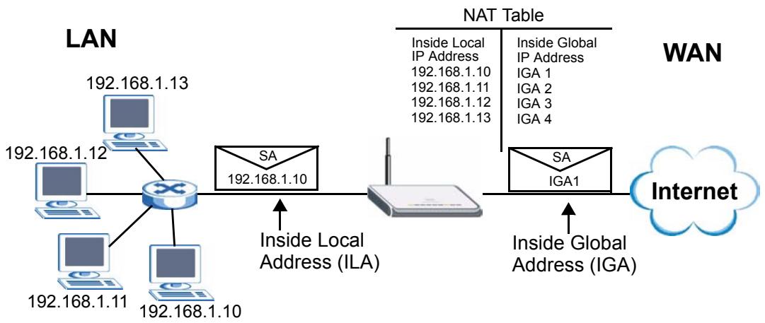
Figure 136 How NAT Works
12.1.4 NAT Application
The following figure illustrates a possible NAT application, where three inside LANs (logical LANs using IP Alias) behind the ZyXEL Device can communicate with three distinct WAN networks. More examples follow at the end of this chapter.
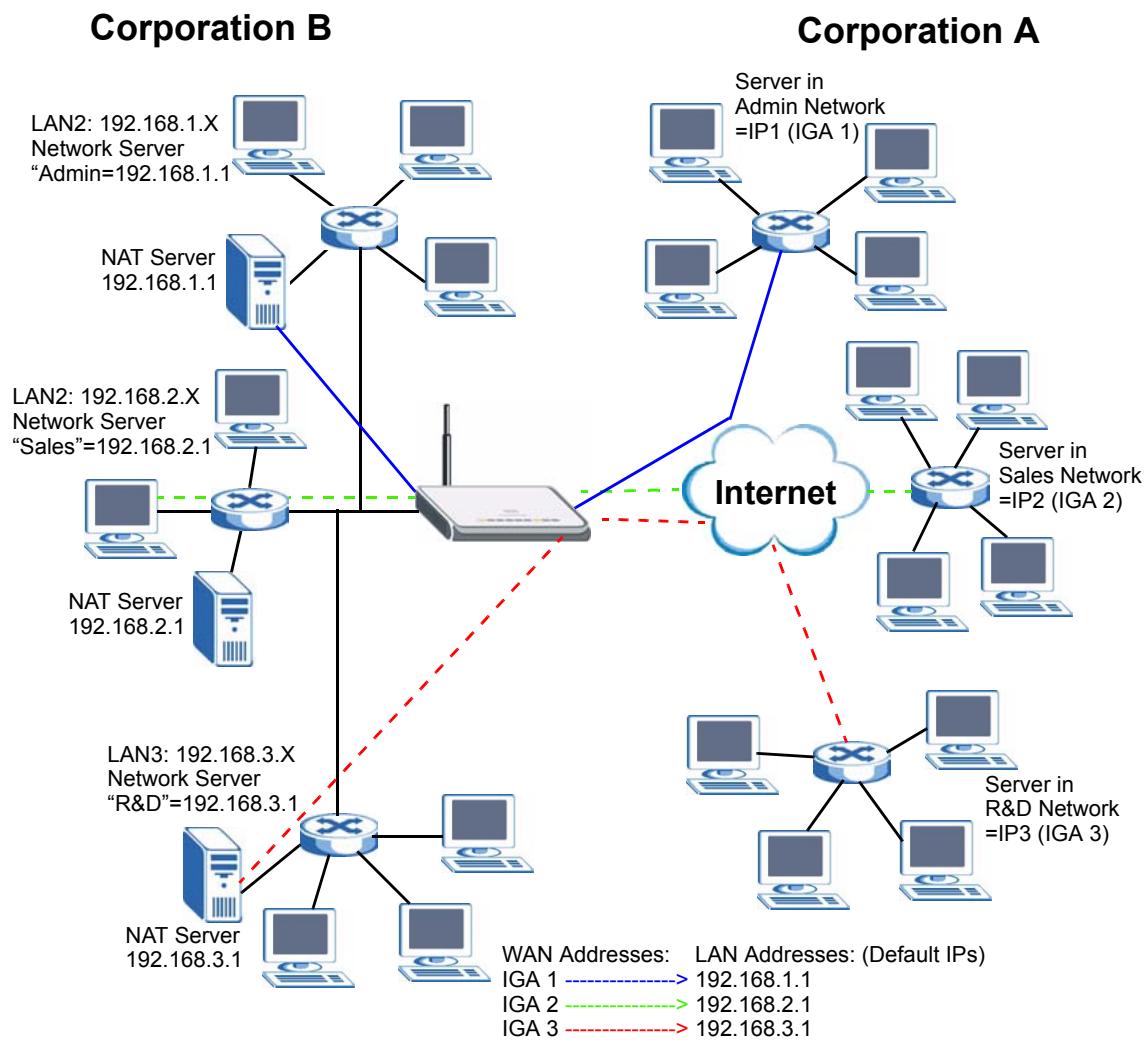
Figure 137 NAT Application With IP Alias
12.1.5 Port Restricted Cone NAT
ZyXEL Device ZyNOS version 4.00 and later uses port restricted cone NAT. Port restricted cone NAT maps all outgoing packets from an internal IP address and port to a single IP address and port on the external network. In the following example, the ZyXEL Device maps the source address of all packets sent from internal IP address 1 and port A to IP address 2 and port B on the external network. A host on the external network (IP address 3 and Port C for example) can only send packets to the internal host if the internal host has already sent a packet to the external host's IP address and port.
A server with IP address 1 and port A sends packets to IP address 3, port C and IP address 4, port D. The ZyXEL Device changes the server's IP address to 2 and port to B.
Since 1, A has already sent packets to 3, C and 4, D, they can send packets back to 2, B and the ZyXEL Device will perform NAT on them and send them to the server at IP address 1, port A.
Packets have not been sent from 1, A to 4, E or 5, so they cannot send packets to 1, A.
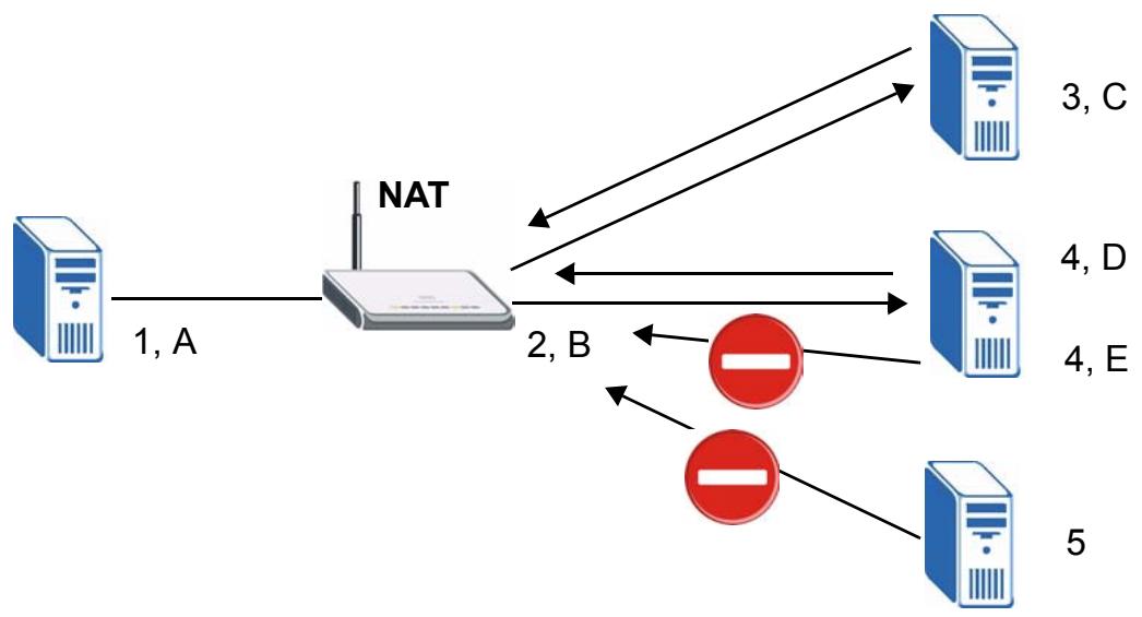
Figure 138 Port Restricted Cone NAT Example
NAT supports five types of IP/port mapping. They are:
- One to One: In One-to-One mode, the ZyXEL Device maps one local IP address to one global IP address.
- Many to One: In Many-to-One mode, the ZyXEL Device maps multiple local IP addresses to one global IP address. This is equivalent to SUA (i.e., PAT, port address translation), ZyXEL's Single User Account feature (the SUA option).
- Many to Many Overload: In Many-to-Many Overload mode, the ZyXEL Device maps the multiple local IP addresses to shared global IP addresses.
- Many One to One: In Many-One-to-One mode, the ZyXEL Device maps each local IP address to a unique global IP address.
- Server: This type allows you to specify inside servers of different services behind the NAT to be accessible to the outside world although, it is highly recommended that you use the DMZ port for these servers instead.

Port numbers do not change for One-to-One and Many-One-to-One NAT mapping types.
The following table summarizes the NAT mapping types.
Table 66 NAT Mapping Types
| TYPE | IP MAPPING |
| One-to-One | ILA1 ↔ IGA1 |
| Many-to-One (SUA/PAT) | ILA1 ↔ IGA1 ILA2 ↔ IGA1 ... |
| Many-to-Many Overload | ILA ↔ IGA1 ILA2 ↔ IGA2 ILA3 ↔ IGA1 ILA4 ↔ IGA2 ... |
| Many-One-to-One | ILA1 ↔ IGA1 ILA2 ↔ IGA2 ILA3 ↔ IGA3 ... |
| Server | Server 1 IP ↔ IGA1 Server 2 IP ↔ IGA1 Server 3 IP ↔ IGA1 |
12.2 Using NAT

You must create a firewall rule in addition to setting up SUA/NAT, to allow traffic from the WAN to be forwarded through the ZyXEL Device.
12.2.1 SUA (Single User Account) Versus NAT
SUA (Single User Account) is a ZyNOS implementation of a subset of NAT that supports two types of mapping, Many-to-One and Server. The ZyXEL Device also supports Full Feature NAT to map multiple global IP addresses to multiple private LAN IP addresses of clients or servers using mapping types. Select either SUA or Full Feature in NAT Overview.
Selecting SUA means (latent) multiple WAN-to-LAN and WAN-to-DMZ address translation. That means that computers on your DMZ with public IP addresses will still have to undergo NAT mapping if you're using SUA NAT mapping. If this is not your intention, then select Full Feature NAT and don't configure NAT mapping rules to those computers with public IP addresses on the DMZ.
12.3 NAT Overview Screen
Click ADVANCED > NAT to open the NAT Overview screen.
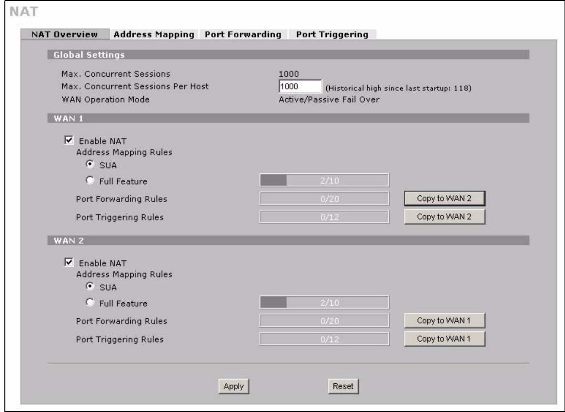
Figure 139 ADVANCED > NAT > NAT Overview
The following table describes the labels in this screen.
Table 67 ADVANCED > NAT > NAT Overview
| LABEL | DESCRIPTION |
| Global Settings | |
| Max. Concurrent Sessions | This read-only field displays the highest number of NAT sessions that the ZyXEL Device will permit at one time. |
| Max. Concurrent Sessions Per Host | Use this field to set the highest number of NAT sessions that the ZyXEL Device will permit a host to have at one time. |
| WAN Operation Mode | This read-only field displays the operation mode of the ZyXEL Device's WAN interfaces. |
| WAN 1, 2 | |
| Enable NAT | Select this check box to turn on the NAT feature for the WAN interface. Clear this check box to turn off the NAT feature for the WAN interface. |
| Address Mapping Rules | Select SUA if you have just one public WAN IP address for your ZyXEL Device. This lets the ZyXEL Device use its permanent, pre-defined NAT address mapping rules. Select Full Feature if you have multiple public WAN IP addresses for your ZyXEL Device. This lets the ZyXEL Device use the address mapping rules that you configure. This is the equivalent of what used to be called full feature NAT or multi-NAT. The bar displays how many of the ZyXEL Device's possible address mapping rules are configured. The first number shows how many address mapping rules are configured on the ZyXEL Device. The second number shows the maximum number of address mapping rules that can be configured on the ZyXEL Device. |
| Port Forwarding Rules | The bar displays how many of the ZyXEL Device's possible port forwarding rules are configured. The first number shows how many port forwarding rules are configured on the ZyXEL Device. The second number shows the maximum number of port forwarding rules that can be configured on the ZyXEL Device. |
| Port Triggering Rules | The bar displays how many of the ZyXEL Device's possible trigger port rules are configured. The first number shows how many trigger port rules are configured on the ZyXEL Device. The second number shows the maximum number of trigger port rules that can be configured on the ZyXEL Device. |
| Copy to WAN 2 (and Copy to WAN 1) | Click Copy to WAN 2 (or Copy to WAN 1) to duplicate this WAN interface's NAT port forwarding or trigger port rules on the other WAN interface. Note: Using the copy button overwrites the other WAN interface's existing rules. The copy button is best suited for initial NAT configuration where you have configured NAT port forwarding or trigger port rules for one interface and want to use similar rules for the other WAN interface. You can use the other NAT screens to edit the NAT rules after you copy them from one WAN interface to the other. |
| Apply | Click Apply to save your changes. |
| Reset | Click Reset to begin configuring this screen afresh. |
12.4 NAT Address Mapping
Click ADVANCED > NAT > Address Mapping to open the following screen.
12.4.1 What NAT Does
In the simplest form, NAT changes the source IP address in a packet received from a subscriber (the inside local address) to another (the inside global address) before forwarding the packet to the WAN side. When the response comes back, NAT translates the destination address (the inside global address) back to the inside local address before forwarding it to the original inside host. Note that the IP address (either local or global) of an outside host is never changed.
See Section 12.1 on page 225 for more on NAT.
Use this screen to change your ZyXEL Device's address mapping settings.
Ordering your rules is important because the ZyXEL Device applies the rules in the order that you specify. When a rule matches the current packet, the ZyXEL Device takes the corresponding action and the remaining rules are ignored. If there are any empty rules before your new configured rule, your configured rule will be pushed up by that number of empty rules. For example, if you have already configured rules 1 to 6 in your current set and now you configure rule number 9. In the set summary screen, the new rule will be rule 7, not 9. Now if you delete rule 4, rules 5 to 7 will be pushed up by 1 rule, so old rules 5, 6 and 7 become new rules 4, 5 and 6.
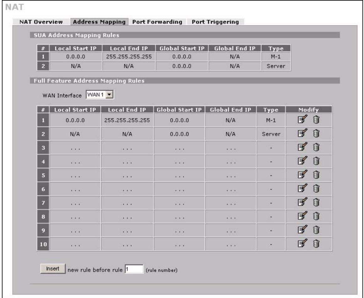
Figure 140 ADVANCED > NAT > Address Mapping
The following table describes the labels in this screen.
Table 68 ADVANCED > NAT > Address Mapping
| LABEL | DESCRIPTION |
| SUA Address Mapping Rules | This read-only table displays the default address mapping rules. |
| Full Feature Address Mapping Rules | |
| WAN Interface | Select the WAN interface for which you want to view or configure address mapping rules. |
| # | This is the rule index number. |
| Local Start IP | This refers to the Inside Local Address (ILA), which is the starting local IP address. If the rule is for all local IP addresses, then this field displays 0.0.0.0 as the Local Start IP address. Local IP addresses are N/A for Server port mapping. |
| Local End IP | This is the end Inside Local Address (ILA). If the rule is for all local IP addresses, then this field displays 255.255.255.255 as the Local End IP address. This field is N/A for One-to-One and Server mapping types. |
| Global Start IP | This refers to the Inside Global IP Address (IGA), that is the starting global IP address. 0.0.0.0 is for a dynamic IP address from your ISP with Many-to-One and Server mapping types. |
| Global End IP | This is the ending Inside Global Address (IGA). This field is N/A for One-to-One, Many-to-One and Server mapping types. |
| Type | 1. One-to-One mode maps one local IP address to one global IP address. Note that port numbers do not change for the One-to-One NAT mapping type. 2. Many-to-One mode maps multiple local IP addresses to one global IP address. This is equivalent to SUA (i.e., PAT, port address translation), ZyXEL's Single User Account feature that previous ZyXEL routers supported only. 3. Many-to-Many Overload mode maps multiple local IP addresses to shared global IP addresses. 4. Many One-to-One mode maps each local IP address to unique global IP addresses. 5. Server allows you to specify inside servers of different services behind the NAT to be accessible to the outside world. |
| Modify | Click the edit icon to go to the screen where you can edit the address mapping rule. Click the delete icon to delete an existing address mapping rule. A window display asking you to confirm that you want to delete the address mapping rule. Note that subsequent address mapping rules move up by one when you take this action. |
| Insert | Click Insert to insert a new mapping rule before an existing one. |
12.4.2 NAT Address Mapping Edit
Click the edit icon to display the NAT Address Mapping Edit screen. Use this screen to edit an address mapping rule. See Section 12.1 on page 225 for information on NAT and address mapping.
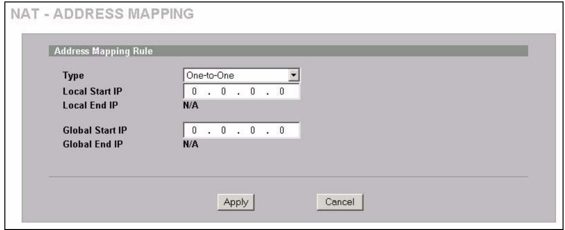
Figure 141 ADVANCED > NAT > Address Mapping > Edit
The following table describes the labels in this screen.
Table 69 ADVANCED > NAT > Address Mapping > Edit
| LABEL | DESCRIPTION |
| Type | Choose the port mapping type from one of the following.1. One-to-One: One-to-One mode maps one local IP address to one global IP address. Note that port numbers do not change for One-to-One NAT mapping type.2. Many-to-One: Many-to-One mode maps multiple local IP addresses to one global IP address. This is equivalent to SUA (i.e., PAT, port address translation), ZyXEL's Single User Account feature.3. Many-to-Many Overload: Many-to-Many Overload mode maps multiple local IP addresses to shared global IP addresses.4. Many One-to-One: Many One-to-One mode maps each local IP address to unique global IP addresses.5. Server: This type allows you to specify inside servers of different services behind the NAT to be accessible to the outside world. |
| Local Start IP | This is the starting Inside Local IP Address (ILA). Local IP addresses are N/A for Server port mapping. |
| Local End IP | This is the end Inside Local IP Address (ILA). If your rule is for all local IP addresses, then enter 0.0.0.0 as the Local Start IP address and 255.255.255.255 as the Local End IP address.This field is N/A for One-to-One and Server mapping types. |
| Global Start IP | This is the starting Inside Global IP Address (IGA). Enter 0.0.0.0 here if you have a dynamic IP address from your ISP. |
| Global End IP | This is the ending Inside Global IP Address (IGA). This field is N/A for One-to-One, Many-to-One and Server mapping types. |
| Apply | Click Apply to save your changes. |
| Cancel | Click Cancel to exit this screen without saving. |
12.5 Port Forwarding
A port forwarding set is a list of inside (behind NAT on the LAN) servers, for example, web or FTP, that you can make visible to the outside world even though NAT makes your whole inside network appear as a single computer to the outside world.
You may enter a single port number or a range of port numbers to be forwarded, and the local IP address of the desired server. The port number identifies a service; for example, web service is on port 80 and FTP on port 21. In some cases, such as for unknown services or where one server can support more than one service (for example both FTP and web service), it might be better to specify a range of port numbers. You can allocate a server IP address that corresponds to a port or a range of ports.
Many residential broadband ISP accounts do not allow you to run any server processes (such as a Web or FTP server) from your location. Your ISP may periodically check for servers and may suspend your account if it discovers any active services at your location. If you are unsure, refer to your ISP.
12.5.1 Default Server IP Address
In addition to the servers for specified services, NAT supports a default server IP address. A default server receives packets from ports that are not specified in this screen.

If you do not assign a Default Server IP address, the ZyXEL Device discards all packets received for ports that are not specified here or in the remote management setup.
12.5.2 Port Forwarding: Services and Port Numbers
The ZyXEL Device provides the additional safety of the DMZ ports for connecting your publicly accessible servers. This makes the LAN more secure by physically separating it from your public servers.
Use the Port Forwarding screen to forward incoming service requests to the server(s) on your local network.
The most often used port numbers are shown in the following table. Please refer to RFC 1700 for further information about port numbers.
Table 70 Services and Port Numbers
| SERVICES | PORT NUMBER |
| ECHO | 7 |
| FTP (File Transfer Protocol) | 21 |
| SMTP (Simple Mail Transfer Protocol) | 25 |
| DNS (Domain Name System) | 53 |
| Finger | 79 |
| HTTP (Hyper Text Transfer protocol or WWW, Web) | 80 |
| POP3 (Post Office Protocol) | 110 |
| NNTP (Network News Transport Protocol) | 119 |
| SNMP (Simple Network Management Protocol) | 161 |
| SNMP trap | 162 |
| PPTP (Point-to-Point Tunneling Protocol) | 1723 |
12.5.3 Configuring Servers Behind Port Forwarding (Example)
Let's say you want to assign ports 21-25 to one FTP, Telnet and SMTP server (A in the example), port 80 to another (B in the example) and assign a default server IP address of 192.168.1.35 to a third (C in the example). You assign the LAN IP addresses and the ISP assigns the WAN IP address. The NAT network appears as a single host on the Internet.
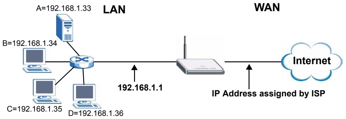
Figure 142 Multiple Servers Behind NAT Example
12.5.4 NAT and Multiple WAN
The ZyXEL Device has two WAN interfaces. You can configure port forwarding and trigger port rule sets for the first WAN interface and separate sets of rules for the second WAN interface.
12.5.5 Port Translation
The ZyXEL Device can translate the destination port number or a range of port numbers of packets coming from the WAN to another destination port number or range of port numbers on the local network. When you use port forwarding without port translation, a single server on the local network can use a specific port number and be accessible to the outside world through a single WAN IP address. When you use port translation with port forwarding, multiple servers on the local network can use the same port number and still be accessible to the outside world through a single WAN IP address.
The following example has two web servers on a LAN. Server A uses IP address 192.168.1.33 and server B uses 192.168.1.34. Both servers use port 80. The letters a.b.c.d represent the WAN port's IP address. The ZyXEL Device translates port 8080 of traffic received on the WAN port (IP address a.b.c.d) to port 80 and sends it to server A (IP address 192.168.1.33). The ZyXEL Device also translates port 8100 of traffic received on the WAN port (also IP address a.b.c.d) to port 80, but sends it to server B (IP address 192.168.1.34).

In this example, anyone wanting to access server A from the Internet must use port 8080. Anyone wanting to access server B from the Internet must use port 8100.
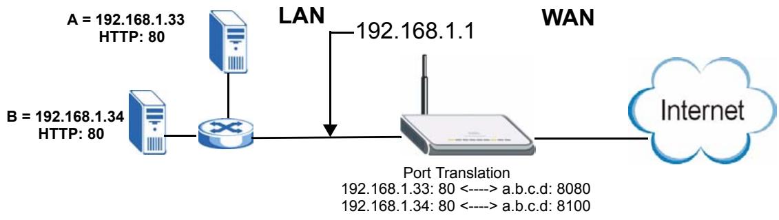
Figure 143 Port Translation Example
12.6 Port Forwarding Screen
Click ADVANCED > NAT > Port Forwarding to open the Port Forwarding screen.

If you do not assign a Default Server IP address, the ZyXEL Device discards all packets received for ports that are not specified here or in the remote management setup.
Refer to Figure 70 on page 236 for port numbers commonly used for particular services.

The last port forwarding rule is reserved for Roadrunner services. The rule is activated only when you set the WAN Encapsulation to Ethernet and the Service Type to something other than Standard.
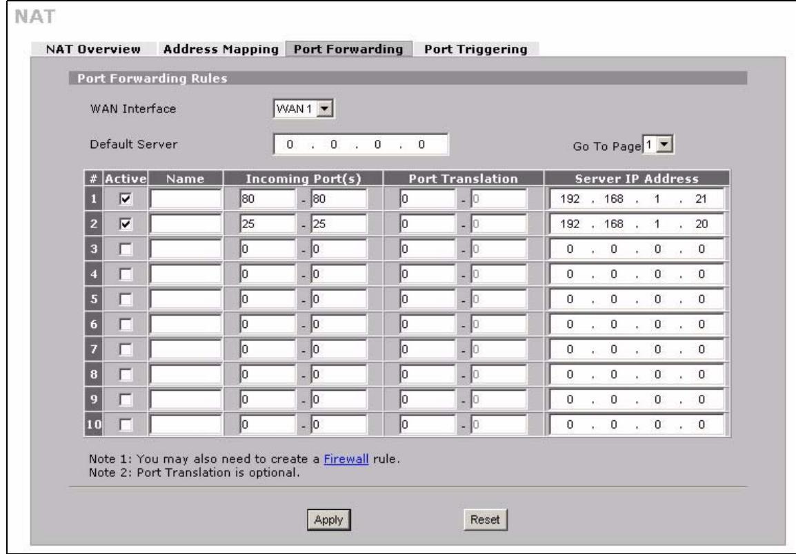
Figure 144 ADVANCED > NAT > Port Forwarding
The following table describes the labels in this screen.
Table 71 ADVANCED > NAT > Port Forwarding
| LABEL | DESCRIPTION |
| WAN Interface | Select the WAN interface for which you want to view or configure address mapping rules. |
| Default Server | In addition to the servers for specified services, NAT supports a default server. A default server receives packets from ports that are not specified in this screen. If you do not assign a Default Server IP address, the ZyXEL Device discards all packets received for ports that are not specified here or in the remote management setup. |
| Go To Page | Choose a page from the drop-down list box to display the corresponding summary page of the port forwarding servers. |
| # | This is the number of an individual port forwarding server entry. |
| Active | Select this check box to enable the port forwarding server entry. Clear this check box to disallow forwarding of these ports to an inside server without having to delete the entry. |
| Name | Enter a name to identify this port-forwarding rule. |
| Incoming Port(s) | Enter a port number here. To forward only one port, enter it again in the second field. To specify a range of ports, enter the last port to be forwarded in the second field. |
| Port Translation | Enter the port number here to which you want the ZyXEL Device to translate the incoming port. For a range of ports, you only need to enter the first number of the range to which you want the incoming ports translated, the ZyXEL Device automatically calculates the last port of the translated port range. |
| Server IP Address | Enter the inside IP address of the server here. |
| Apply | Click Apply to save your changes. |
| Reset | Click Reset to begin configuring this screen afresh. |
12.7 Port Triggering
Some services use a dedicated range of ports on the client side and a dedicated range of ports on the server side. With regular port forwarding you set a forwarding port in NAT to forward a service (coming in from the server on the WAN) to the IP address of a computer on the client side (LAN). The problem is that port forwarding only forwards a service to a single LAN IP address. In order to use the same service on a different LAN computer, you have to manually replace the LAN computer's IP address in the forwarding port with another LAN computer's IP address.
Trigger port forwarding solves this problem by allowing computers on the LAN to dynamically take turns using the service. The ZyXEL Device records the IP address of a LAN computer that sends traffic to the WAN to request a service with a specific port number and protocol (a "trigger" port). When the ZyXEL Device's WAN port receives a response with a specific port number and protocol ("incoming" port), the ZyXEL Device forwards the traffic to the LAN IP address of the computer that sent the request. After that computer's connection for that service closes, another computer on the LAN can use the service in the same manner. This way you do not need to configure a new IP address each time you want a different LAN computer to use the application.
For example:
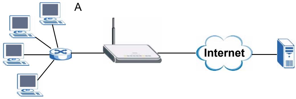
Figure 145 Trigger Port Forwarding Process: Example
1 Jane (A) requests a file from the Real Audio server (port 7070).
2 Port 7070 is a "trigger" port and causes the ZyXEL Device to record Jane's computer IP address. The ZyXEL Device associates Jane's computer IP address with the "incoming" port range of 6970-7170.
3 The Real Audio server responds using a port number ranging between 6970-7170.
4 The ZyXEL Device forwards the traffic to Jane's computer IP address.
5 Only Jane can connect to the Real Audio server until the connection is closed or times out. The ZyXEL Device times out in three minutes with UDP (User Datagram Protocol) or two hours with TCP/IP (Transfer Control Protocol/Internet Protocol).
Click ADVANCED > NAT > Port Triggering to open the following screen. Use this screen to change your ZyXEL Device's trigger port settings.
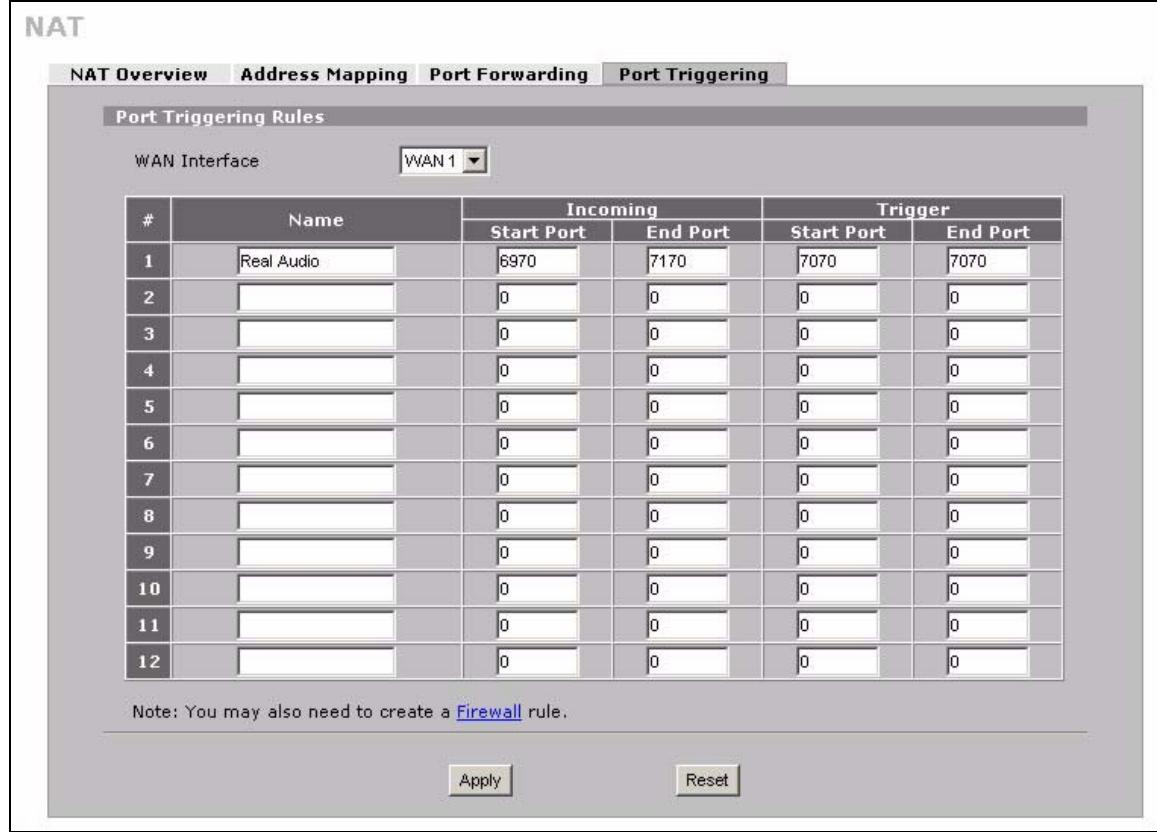
Figure 146 ADVANCED > NAT > Port Triggering
The following table describes the labels in this screen.
Table 72 ADVANCED > NAT > Port Triggering
| LABEL | DESCRIPTION |
| WAN Interface | Select the WAN interface for which you want to view or configure address mapping rules. |
| # | This is the rule index number (read-only). |
| Name | Type a unique name (up to 15 characters) for identification purposes. All characters are permitted - including spaces. |
| Incoming | Incoming is a port (or a range of ports) that a server on the WAN uses when it sends out a particular service. The ZyXEL Device forwards the traffic with this port (or range of ports) to the client computer on the LAN that requested the service. |
| Start Port | Type a port number or the starting port number in a range of port numbers. |
| End Port | Type a port number or the ending port number in a range of port numbers. |
| Trigger | The trigger port is a port (or a range of ports) that causes (or triggers) the ZyXEL Device to record the IP address of the LAN computer that sent the traffic to a server on the WAN. |
| Start Port | Type a port number or the starting port number in a range of port numbers. |
| End Port | Type a port number or the ending port number in a range of port numbers. |
| Apply | Click Apply to save your changes. |
| Reset | Click Reset to begin configuring this screen afresh. |
This chapter shows you how to configure static routes for your ZyXEL Device.
13.1 IP Static Route
The ZyXEL Device usually uses the default gateway to route outbound traffic from local computers to the Internet. To have the ZyXEL Device send data to devices not reachable through the default gateway, use static routes.
For example, the next figure shows a computer (A) connected to the ZyXEL Device's LAN interface. The ZyXEL Device routes most traffic from A to the Internet through the default gateway (R1). You create one static route to connect to services offered by your ISP behind router R2. You create another static route to communicate with a separate network behind a router (R3) connected to the LAN.
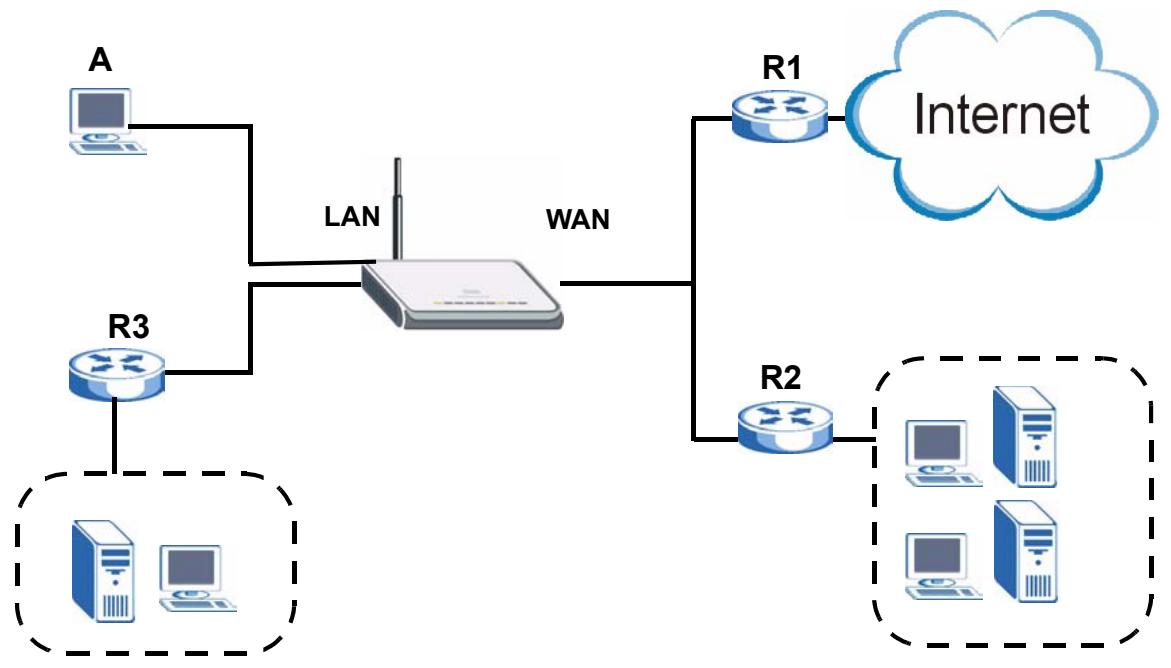
Figure 147 Example of Static Routing Topology
13.2 IP Static Route
Click ADVANCED > STATIC ROUTE to open the IP Static Route screen.
The first two static route entries are for default WAN 1 and WAN 2 routes on a ZyXEL Device with multiple WAN interfaces. You cannot modify or delete a static default route.
The default route is disabled after you change the static WAN IP address to a dynamic WAN IP address.
STATIC ROUTE
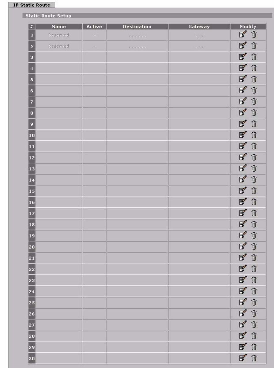
Figure 148 ADVANCED >STATIC ROUTE >IP Static Route
The following table describes the labels in this screen.
Table 73 ADVANCED >STATIC ROUTE >IP Static Route
| LABEL | DESCRIPTION |
| # | This is the number of an individual static route. |
| Name | This is the name that describes or identifies this route. |
| Active | This field shows whether this static route is active (Yes) or not (No). |
| Destination | This parameter specifies the IP network address of the final destination. Routing is always based on network number. |
| Gateway | This is the IP address of the gateway. The gateway is a router or switch on the same network segment as the ZyXEL Device's interface. The gateway helps forward packets to their destinations. |
| Modify | Click the edit icon to go to the screen where you can set up a static route on the ZyXEL Device. Click the delete icon to remove a static route from the ZyXEL Device. A window displays asking you to confirm that you want to delete the route. |
13.2.1 IP Static Route Edit
Click the edit icon in the IP Static Route screen. The screen shown next appears. Use this screen to configure the required information for a static route.
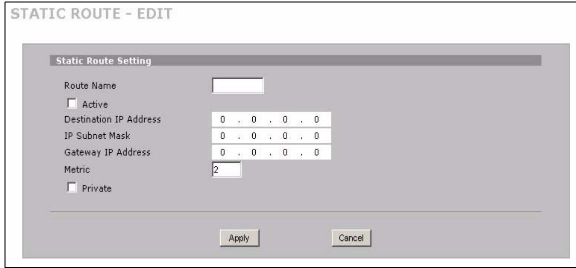
Figure 149 ADVANCED >STATIC ROUTE >IP Static Route >Edit
The following table describes the labels in this screen.
Table 74 ADVANCED >STATIC ROUTE > IP Static Route > Edit
| LABEL | DESCRIPTION |
| Route Name | Enter the name of the IP static route. Leave this field blank to delete this static route. |
| Active | This field allows you to activate/deactivate this static route. |
| Destination IP Address | This parameter specifies the IP network address of the final destination. Routing is always based on network number. If you need to specify a route to a single host, use a subnet mask of 255.255.255.255 in the subnet mask field to force the network number to be identical to the host ID. |
| IP Subnet Mask | Enter the IP subnet mask here. |
Table 74 ADVANCED >STATIC ROUTE > IP Static Route > Edit
| LABEL | DESCRIPTION |
| Gateway IP Address | Enter the IP address of the gateway. The gateway is a router or switch on the same network segment as the device's LAN or WAN port. The gateway helps forward packets to their destinations. |
| Metric | Metric represents the “cost” of transmission for routing purposes. IP routing uses hop count as the measurement of cost, with a minimum of 1 for directly connected networks. Enter a number that approximates the cost for this link. The number need not be precise, but it must be between 1 and 15. In practice, 2 or 3 is usually a good number. |
| Private | This parameter determines if the ZyXEL Device will include this route to a remote node in its RIP broadcasts. Select this check box to keep this route private and not included in RIP broadcasts. Clear this check box to propagate this route to other hosts through RIP broadcasts. |
| Apply | Click Apply to save your changes. |
| Cancel | Click Cancel to exit this screen without saving. |
This chapter shows you how to configure the DNS screens.
14.1 DNS Overview
DNS (Domain Name System) is for mapping a domain name to its corresponding IP address and vice versa. The DNS server is extremely important because without it, you must know the IP address of a machine before you can access it. The ZyXEL Device uses a system DNS server (in the order you specify in the DNS System screen) to resolve domain names, for example, DDNS and the time server.
14.2 DNS Server Address Assignment
The ZyXEL Device can get the DNS server addresses in the following ways.
1 The ISP tells you the DNS server addresses, usually in the form of an information sheet, when you sign up. If your ISP gives you DNS server addresses, manually enter them in the DNS server fields.
2 If your ISP dynamically assigns the DNS server IP addresses (along with the ZyXEL Device's WAN IP address), set the DNS server fields to get the DNS server address from the ISP.
3 You can manually enter the IP addresses of other DNS servers. These servers can be public or private. A DNS server could even be behind a remote IPSec router (see Section 14.5.1 on page 248).
14.3 DNS Servers
There are three places where you can configure DNS setup on the ZyXEL Device.
1 Use the DNS System screen to configure the ZyXEL Device to use a DNS server to resolve domain names for ZyXEL Device system features such as DDNS and the time server.
2 Use the DNS DHCP screen to configure the DNS server information that the ZyXEL Device sends to the DHCP client devices on the LAN or DMZ.
3 Use the REMOTE MGMT DNS screen to configure the ZyXEL Device to accept or discard DNS queries.
14.4 Address Record
An address record contains the mapping of a fully qualified domain name (FQDN) to an IP address. An FQDN consists of a host and domain name and includes the top-level domain. For example, www.zyxel.com.tw is a fully qualified domain name, where “www” is the host, “zyxel” is the second-level domain, and “com.tw” is the top level domain.
mail.myZyXEL.com.tw is also a FQDN, where "mail" is the host, "myZyXEL" is the second-level domain, and "com.tw" is the top level domain.
The ZyXEL Device allows you to configure address records about the ZyXEL Device itself or another device. This way you can keep a record of DNS names and addresses that people on your network may use frequently. If the ZyXEL Device receives a DNS query for an FQDN for which the ZyXEL Device has an address record, the ZyXEL Device can send the IP address in a DNS response without having to query a DNS name server.
14.4.1 DNS Wildcard
Enabling the wildcard feature for your host causes *.yourhost.com to be aliased to the same IP address as yourhost.com. This feature is useful if you want to be able to use, for example, www.yourhost.com and still reach your hostname.
14.5 Name Server Record
A name server record contains a DNS server's IP address. The ZyXEL Device can query the DNS server to resolve domain names for features such as DDNS and the time server. A domain zone may also be included. A domain zone is a fully qualified domain name without the host. For example, zyxel.com.tw is the domain zone for the www.zyxel.com.tw fully qualified domain name.
14.5.1 Private DNS Server
In cases where you want to use domain names to access Intranet servers on a remote private network that has a DNS server, you must identify that DNS server. You cannot use DNS servers on the LAN or from the ISP since these DNS servers cannot resolve domain names to private IP addresses on the remote private network.
14.6 System Screen
Click ADVANCED > DNS to display the following screen. Use this screen to configure your ZyXEL Device's DNS address and name server records.
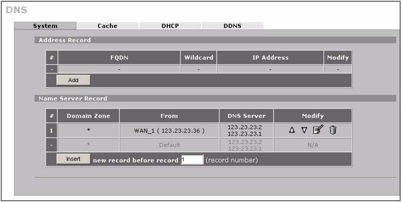
Figure 150 ADVANCED > DNS > System DNS
The following table describes the labels in this screen.
| LABEL | DESCRIPTION |
| Address Record | An address record specifies the mapping of a fully qualified domain name (FQDN) to an IP address. An FQDN consists of a host and domain name and includes the top-level domain. For example, www.zyxel.com.tw is a fully qualified domain name, where “www” is the host, “zyxel” is the second-level domain, and “com.tw” is the top level domain. |
| # | This is the index number of the address record. |
| FQDN | This is a host's fully qualified domain name. |
| Wildcard | This column displays whether or not the DNS wildcard feature is enabled for this domain name. |
| IP Address | This is the IP address of a host. |
| Modify | Click the edit icon to go to the screen where you can edit the record. Click the delete icon to remove an existing record. A window display asking you to confirm that you want to delete the record. Note that subsequent records move up by one when you take this action. |
| Add | Click Add to open a screen where you can add a new address record. Refer to Table 75 on page 251 for information on the fields. |
| Name Server Record | A name server record contains a DNS server's IP address. The ZyXEL Device can query the DNS server to resolve domain names for features such as DDNS and the time server. When the ZyXEL Device needs to resolve a domain name, it checks it against the name server record entries in the order that they appear in this list. A “*” indicates a name server record without a domain zone. The default record is grayed out. The ZyXEL Device uses this default record if the domain name that needs to be resolved does not match any of the other name server records. A name server record with a domain zone is always put before a record without a domain zone. |
| # | This is the index number of the name server record. |
| Domain Zone | A domain zone is a fully qualified domain name without the host. For example, zyxel.com.tw is the domain zone for the www.zyxel.com.tw fully qualified domain name. |
| From | This field displays whether the IP address of a DNS server is from a WAN interface (and which it is) or specified by the user. |
| DNS Server | This is the IP address of a DNS server. |
| Modify | Click a triangle icon to move the record up or down in the list. Click the edit icon to go to the screen where you can edit the record. Click the delete icon to remove an existing record. A window display asking you to confirm that you want to delete the record. Note that subsequent records move up by one when you take this action. |
| Insert | Click Insert to open a screen where you can insert a new name server record. Refer to Table 76 on page 252 for information on the fields. |
14.6.1 Adding an Address Record
Click Add in the System screen to open this screen. Use this screen to add an address record. An address record contains the mapping of a fully qualified domain name (FQDN) to an IP address. Configure address records about the ZyXEL Device itself or another device to keep a record of DNS names and addresses that people on your network may use frequently. If the ZyXEL Device receives a DNS query for an FQDN for which the ZyXEL Device has an address record, the ZyXEL Device can send the IP address in a DNS response without having to query a DNS name server. See Section 14.4 on page 248 for more on address records.
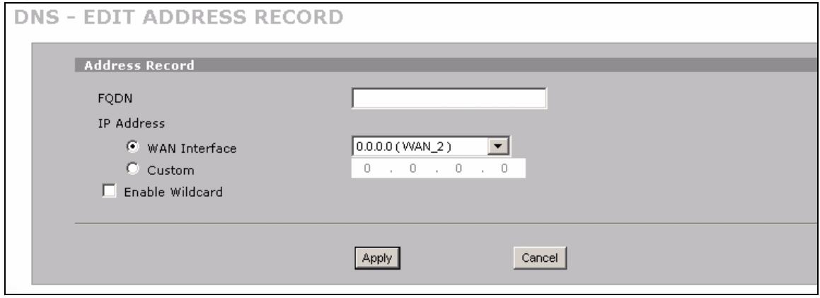
Figure 151 ADVANCED > DNS > Add (Address Record)
The following table describes the labels in this screen.
Table 75 ADVANCED > DNS > Add (Address Record)
| LABEL | DESCRIPTION |
| FQDN | Type a fully qualified domain name (FQDN) of a server. An FQDN starts with a host name and continues all the way up to the top-level domain name. For example, www.zyxel.com.tw is a fully qualified domain name, where “www” is the host, “zyxel” is the second-level domain, and “com.tw” is the top level domain. |
| IP Address | If this entry is for one of the WAN ports on a ZyXEL Device with multiple WAN ports, select WAN Interface and select WAN 1 or WAN 2 from the drop-down list box. If this entry is for the WAN port on a ZyXEL Device with a single WAN port, select WAN Interface. For entries that are not for the WAN port(s), select Custom and enter the IP address of the host in dotted decimal notation. |
| Enable Wildcard | Select the check box to enable DNS wildcard. |
| Apply | Click Apply to save your changes. |
| Cancel | Click Cancel to exit this screen without saving. |
14.6.2 Inserting a Name Server Record
Click Insert in the System screen to open this screen. Use this screen to insert a name server record. A name server record contains a DNS server's IP address. The ZyXEL Device can query the DNS server to resolve domain names for features such as DDNS and the time server. A domain zone may also be included. A domain zone is a fully qualified domain name without the host. For example, zyxel.com.tw is the domain zone for the www.zyxel.com.tw fully qualified domain name.
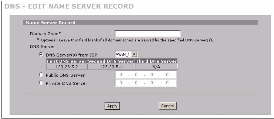
Figure 152 ADVANCED > DNS > Insert (Name Server Record)
The following table describes the labels in this screen.
| LABEL | DESCRIPTION |
| Domain Zone | This field is optional.A domain zone is a fully qualified domain name without the host. For example,zyxel.com.tw is the domain zone for the www.zyxel.com.tw fully qualified domainname. For example, whenever the ZyxEL Device receives needs to resolve azyxel.com.tw domain name, it can send a query to the recorded name server IPaddress.Leave this field blank if all domain zones are served by the specified DNS server(s). |
| DNS Server | Select the DNS Server(s) from ISP radio button if your ISP dynamically assignsDNS server information. You also need to select an interface through which the ISPprovides the DNS server IP address(es). The interface should be activated and setas a DHCP client.The fields below display the (read-only) DNS server IPaddress(es) that the ISP assigns. N/A displays for any DNS server IP address fieldsfor which the ISP does not assign an IP address. N/A displays for all of the DNSserver IP address fields if the ZyXEL Device has a fixed WAN IP address.Select Public DNS Server if you have the IP address of a DNS server. The IPaddress must be public or a private address on your local LAN. Enter the DNSserver's IP address in the field to the right.Public DNS Server entries with the IP address set to 0.0.0.0 are not allowed.Select Private DNS Server if the DNS server has a private IP address and is locatedin a local network. Enter the DNS server's IP address in the field to the right.With a private DNS server, you must also configure the first DNS server entry for theLAN or DMZ in the DNS DHCP screen to use DNS Relay.Private DNS Server entries with the IP address set to 0.0.0.0 are not allowed. |
| Apply | Click Apply to save your changes. |
| Cancel | Click Cancel to exit this screen without saving. |
14.7 DNS Cache
DNS cache is the temporary storage area where a router stores responses from DNS servers. When the ZyXEL Device receives a positive or negative response for a DNS query, it records the response in the DNS cache. A positive response means that the ZyXEL Device received the IP address for a domain name that it checked with a DNS server within the five second DNS timeout period. A negative response means that the ZyXEL Device did not receive a response for a query it sent to a DNS server within the five second DNS timeout period.
When the ZyXEL Device receives DNS queries, it compares them against the DNS cache before querying a DNS server. If the DNS query matches a positive entry, the ZyXEL Device responses with the IP address from the entry. If the DNS query matches a negative entry, the ZyXEL Device replies that the DNS query failed.
14.8 Configure DNS Cache
To configure your ZyXEL Device's DNS caching, click ADVANCED > DNS > Cache. The screen appears as shown.
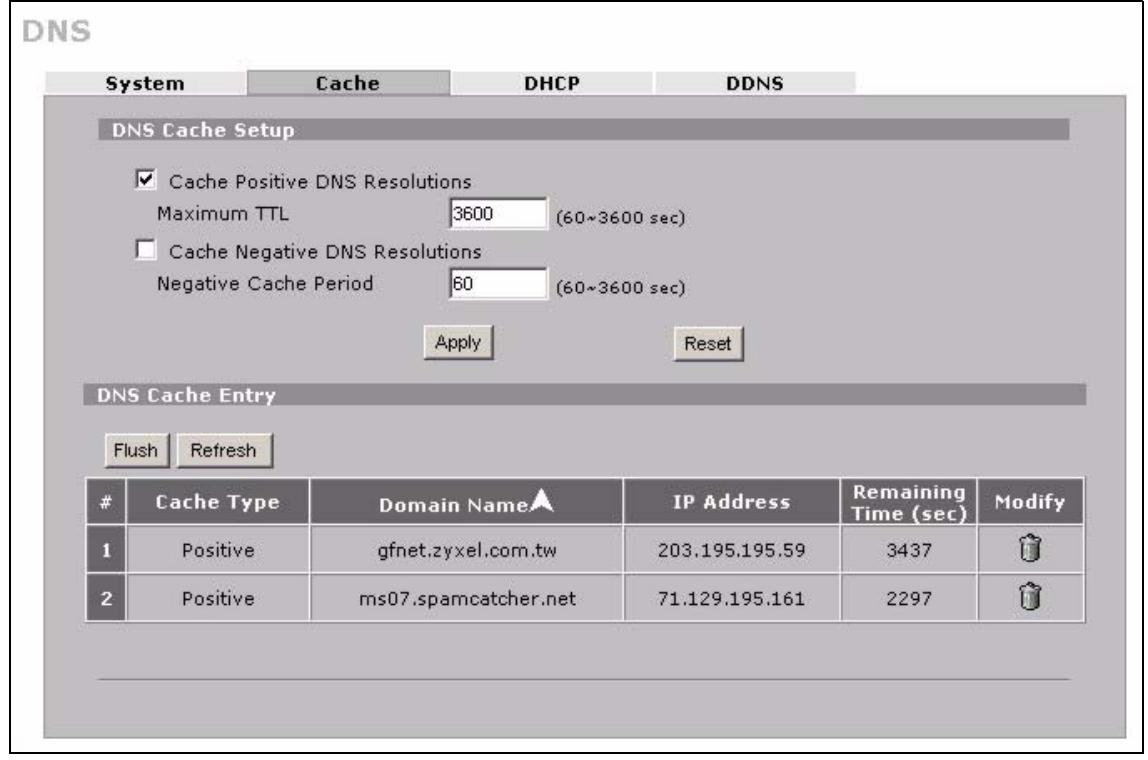
Figure 153 ADVANCED > DNS > Cache
The following table describes the labels in this screen.
| LABEL | DESCRIPTION |
| DNS Cache Setup | |
| Cache Positive DNS Resolutions | Select the check box to record the positive DNS resolutions in the cache.Caching positive DNS resolutions helps speed up the ZyXEL Device's processing of commonly queried domain names and reduces the amount of traffic that the ZyXEL Device sends out to the WAN. |
| Maximum TTL | Type the maximum time to live (TTL) (60 to 3600 seconds). This sets how long the ZyXEL Device is to allow a positive resolution entry to remain in the DNS cache before discarding it. |
| Cache Negative DNS Resolutions | Caching negative DNS resolutions helps speed up the ZyXEL Device's processing of commonly queried domain names (for which DNS resolution has failed) and reduces the amount of traffic that the ZyXEL Device sends out to the WAN. |
| Negative Cache Period | Type the time (60 to 3600 seconds) that the ZyXEL Device is to allow a negative resolution entry to remain in the DNS cache before discarding it. |
| Apply | Click Apply to save your changes back to the ZyXEL Device. |
| Reset | Click Reset to begin configuring this screen afresh. |
| DNS Cache Entry | |
| Flush | Click this button to clear the cache manually. After you flush the cache, the ZyXEL Device must query the DNS servers again for any domain names that had been previously resolved. |
| Refresh | Click this button to reload the cache. |
| # | This is the index number of a record. |
| Cache Type | This displays whether the response for the DNS request is positive or negative. |
| Domain Name | This is the domain name of a host. |
| IP Address | This is the (resolved) IP address of a host. This field displays 0.0.0.0 for negative DNS resolution entries. |
| Remaining Time (sec) | This is the number of seconds left before the DNS resolution entry is discarded from the cache. |
| Modify | Click the delete icon to remove the DNS resolution entry from the cache. |
14.9 Configuring DNS DHCP
Click ADVANCED > DNS > DHCP to open the DNS DHCP screen shown next. Use this screen to configure the DNS server information that the ZyXEL Device sends to its LAN or DMZ DHCP clients.
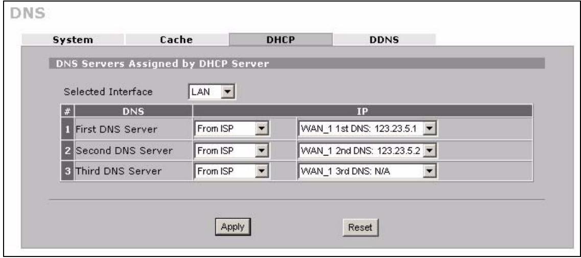
Figure 154 ADVANCED > DNS > DHCP
The following table describes the labels in this screen.
| LABEL | DESCRIPTION |
| DNS Servers Assigned by DHCP Server | The ZyXEL Device passes a DNS (Domain Name System) server IP address to the DHCP clients. |
| Selected Interface | Select an interface from the drop-down list box to configure the DNS servers for the specified interface. |
| DNS | These read-only labels represent the DNS servers. |
| IP | Select From ISP if your ISP dynamically assigns DNS server information (and the ZyxEL Device's WAN IP address). Use the drop-down list box to select a DNS server IP address that the ISP assigns in the field to the right. Select User-Defined if you have the IP address of a DNS server. Enter the DNS server's IP address in the field to the right. If you chose User-Defined, but leave the IP address set to 0.0.0.0, User-Defined changes to None after you click Apply. If you set a second choice to User-Defined, and enter the same IP address, the second User-Defined changes to None after you click Apply. Select DNS Relay to have the ZyxEL Device act as a DNS proxy. The ZyxEL Device's LAN or DMZ IP address displays in the field to the right (read-only). The ZyxEL Device tells the DHCP clients on the LAN or DMZ that the ZyxEL Device itself is the DNS server. When a computer on the LAN or DMZ sends a DNS query to the ZyxEL Device, the ZyxEL Device forwards the query to the ZyxEL Device's system DNS server (configured in the DNS System screen) and relays the response back to the computer. You can only select DNS Relay for one of the three servers; if you select DNS Relay for a second or third DNS server, that choice changes to None after you click Apply. Select None if you do not want to configure DNS servers. You must have another DHCP sever on your LAN, or else the computers must have their DNS server addresses manually configured. If you do not configure a DNS server, you must know the IP address of a computer in order to access it. |
| Apply | Click Apply to save your changes. |
| Reset | Click Reset to begin configuring this screen afresh. |
14.10 Dynamic DNS
Dynamic DNS allows you to update your current dynamic IP address with one or many dynamic DNS services so that anyone can contact you (in NetMeeting, CU-SeeMe, etc.). You can also access your FTP server or Web site on your own computer using a domain name (for instance myhost.dhs.org, where myhost is a name of your choice) that will never change instead of using an IP address that changes each time you reconnect. Your friends or relatives will always be able to call you even if they don't know your IP address.
First of all, you need to have registered a dynamic DNS account with www.dyndns.org. This is for people with a dynamic IP from their ISP or DHCP server that would still like to have a domain name. The Dynamic DNS service provider will give you a password or key.

You must go to the Dynamic DNS service provider's website and register a user account and a domain name before you can use the Dynamic DNS service with your ZyXEL Device.
14.10.1 DYNDNS Wildcard
Enabling the wildcard feature for your host causes *.yourhost.dyndns.org to be aliased to the same IP address as yourhost.dyndns.org. This feature is useful if you want to be able to use, for example, www.yourhost.dyndns.org and still reach your hostname.

If you have a private WAN IP address, then you cannot use Dynamic DNS.
14.10.2 High Availability
A DNS server maps a domain name to a port's IP address. If that WAN port loses its connection, high availability allows the router to substitute another port's IP address for the domain name mapping.
14.11 Configuring Dynamic DNS
To change your ZyXEL Device's DDNS, click ADVANCED > DNS > DDNS. The screen appears as shown.
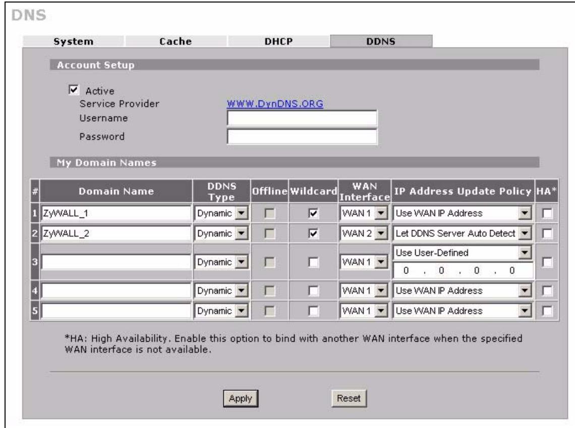
Figure 155 ADVANCED > DNS > DDNS
The following table describes the labels in this screen.
| LABEL | DESCRIPTION |
| Account Setup | |
| Active | Select this check box to use dynamic DNS. |
| Service Provider | This is the name of your Dynamic DNS service provider. |
| Username | Enter your user name. You can use up to 31 alphanumeric characters (and the underscore). Spaces are not allowed. |
| Password | Enter the password associated with the user name above. You can use up to 31 alphanumeric characters (and the underscore). Spaces are not allowed. |
| My Domain Names | |
| Domain Name 1~5 | Enter the host names in these fields. |
| DDNS Type | Select the type of service that you are registered for from your Dynamic DNS service provider. Select Dynamic if you have the Dynamic DNS service. Select Static if you have the Static DNS service. Select Custom if you have the Custom DNS service. |
| Offline | This option is available when Custom is selected in the DDNS Type field. Check with your Dynamic DNS service provider to have traffic redirected to a URL (that you can specify) while you are off line. |
| Wildcard | Select the check box to enable DYNDNS Wildcard. |
| WAN Interface | Select the WAN interface to use for updating the IP address of the domain name. |
| IP Address Update Policy | Select Use WAN IP Address to have the ZyXEL Device update the domain name with the WAN interface's IP address. Select Use User-Defined and enter the IP address if you have a static IP address. Select Let DDNS Server Auto Detect only when there are one or more NAT routers between the ZyXEL Device and the DDNS server. This feature has the DDNS server automatically detect and use the IP address of the NAT router that has a public IP address. Note: The DDNS server may not be able to detect the proper IP address if there is an HTTP proxy server between the ZyXEL Device and the DDNS server. |
| HA | Select this check box to enable the high availability (HA) feature. High availability has the ZyXEL Device update a domain name with another interface's IP address when the normal WAN interface does not have a connection. The ZyXEL Device will update the domain name with the IP address of whichever WAN interface has a connection, regardless of the setting in the WAN Interface field. Disable this feature and the ZyXEL Device will only update the domain name with an IP address of the WAN interface specified in the WAN Interface field. If that WAN interface does not have a connection, the ZyXEL Device will not update the domain name with another port's IP address. Note: DDNS does not function when the ZyXEL Device uses traffic redirect. |
| Apply | Click Apply to save your changes. |
| Reset | Click Reset to begin configuring this screen afresh. |
Remote Management
This chapter provides information on the Remote Management screens.
15.1 Remote Management Overview
Remote management allows you to determine which services/protocols can access which ZyXEL Device interface (if any) from which computers.
The following figure shows secure and insecure management of the ZyXEL Device coming in from the WAN. HTTPS and SSH access are secure. HTTP and Telnet access are not secure.
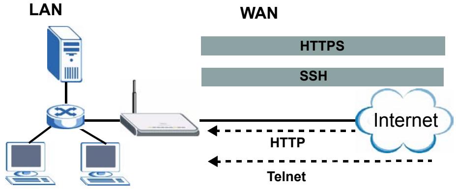
Figure 156 Secure and Insecure Remote Management From the WAN

When you configure remote management to allow management from any network except the LAN, you still need to configure a firewall rule to allow access. See Chapter 9 on page 167 for details on configuring firewall rules.
You can also disable a service on the ZyXEL Device by not allowing access for the service/protocol through any of the ZyXEL Device interfaces.
You may only have one remote management session running at a time. The ZyXEL Device automatically disconnects a remote management session of lower priority when another remote management session of higher priority starts. The priorities for the different types of remote management sessions are as follows.
1 Console port
2 SSH
3 Telnet
4 HTTPS and HTTP
15.1.1 Remote Management Limitations
Remote management does not work when:
1 You have not enabled that service on the interface in the corresponding remote management screen.
2 You have disabled that service in one of the remote management screens.
3 The IP address in the Secure Client IP Address field does not match the client IP address. If it does not match, the ZyXEL Device will disconnect the session immediately.
4 There is already another remote management session with an equal or higher priority running. You may only have one remote management session running at one time.
5 There is a firewall rule that blocks it.
6 A filter is applied (through the commands) to block a Telnet, FTP or Web service.
15.1.2 System Timeout
There is a default system management idle timeout of five minutes (three hundred seconds). The ZyXEL Device automatically logs you out if the management session remains idle for longer than this timeout period. The management session does not time out when a statistics screen is polling. You can change the timeout period in the MAINTENANCE > General screen.
15.2 WWW (HTTP and HTTPS)
HTTPS (HyperText Transfer Protocol over Secure Socket Layer, or HTTP over SSL) is a web protocol that encrypts and decrypts web pages. Secure Socket Layer (SSL) is an application-level protocol that enables secure transactions of data by ensuring confidentiality (an unauthorized party cannot read the transferred data), authentication (one party can identify the other party) and data integrity (you know if data has been changed).
It relies upon certificates, public keys, and private keys (see Chapter 11 on page 195 for more information).
HTTPS on the ZyXEL Device is used so that you may securely access the ZyXEL Device using the web configurator. The SSL protocol specifies that the SSL server (the ZyXEL Device) must always authenticate itself to the SSL client (the computer which requests the HTTPS connection with the ZyXEL Device), whereas the SSL client only should authenticate itself when the SSL server requires it to do so (select Authenticate Client Certificates in the REMOTE MGMT > WWW screen). Authenticate Client Certificates is optional and if selected means the SSL-client must send the ZyXEL Device a certificate. You must apply for a certificate for the browser from a CA that is a trusted CA on the ZyXEL Device.
Please refer to the following figure.
1 HTTPS connection requests from an SSL-aware web browser go to port 443 (by default) on the ZyXEL Device's WS (web server).
2 HTTP connection requests from a web browser go to port 80 (by default) on the ZyXEL Device's WS (web server).
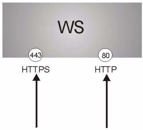
Figure 157 HTTPS Implementation

If you disable the HTTP service in the REMOTE MGMT > WWW screen, then the ZyXEL Device blocks all HTTP connection attempts.
15.3 WWW
Click ADVANCED > REMOTE MGMT to open the WWW screen. Use this screen to configure the ZyXEL Device's HTTP and HTTPS management settings.
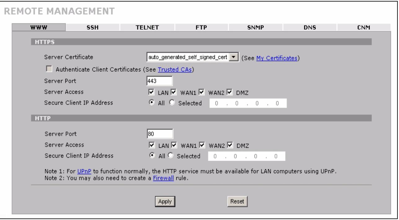
Figure 158 ADVANCED > REMOTE MGMT > WWW
The following table describes the labels in this screen.
Table 76 ADVANCED > REMOTE MGMT > WWW
| LABEL | DESCRIPTION |
| HTTPS | |
| Server Certificate | Select the Server Certificate that the ZyXEL Device will use to identify itself. The ZyXEL Device is the SSL server and must always authenticate itself to the SSL client (the computer which requests the HTTPS connection with the ZyXEL Device). |
| Authentication Client Certificates | Select Authentication Client Certificates (optional) to require the SSL client to authenticate itself to the ZyXEL Device by sending the ZyXEL Device a certificate. To do that the SSL client must have a CA-signed certificate from a CA that has been imported as a trusted CA on the ZyXEL Device (see Appendix F on page 403 on importing certificates for details). |
| Server Port | The HTTPS proxy server listens on port 443 by default. If you change the HTTPS proxy server port to a different number on the ZyXEL Device, for example 8443, then you must notify people who need to access the ZyXEL Device web configurator to use “https://ZyXEL Device IP Address:8443” as the URL. |
| Server Access | Select the interface(s) through which a computer may access the ZyXEL Device using this service. You can allow only secure web configurator access by clearing all of the interface check boxes in the HTTP Server Access field and setting the HTTPS Server Access field to an interface(s). |
| Secure Client IP Address | A secure client is a “trusted” computer that is allowed to communicate with the ZyXEL Device using this service. Select All to allow any computer to access the ZyXEL Device using this service. Choose Selected to just allow the computer with the IP address that you specify to access the ZyXEL Device using this service. |
| HTTP | |
| Server Port | You may change the server port number for a service if needed, however you must use the same port number in order to use that service for remote management. |
| Server Access | Select the interface(s) through which a computer may access the ZyXEL Device using this service. |
| Secure Client IP Address | A secure client is a “trusted” computer that is allowed to communicate with the ZyXEL Device using this service. Select All to allow any computer to access the ZyXEL Device using this service. Choose Selected to just allow the computer with the IP address that you specify to access the ZyXEL Device using this service. |
| Apply | Click Apply to save your customized settings and exit this screen. |
| Reset | Click Reset to begin configuring this screen afresh. |
15.4 HTTPS Example
If you haven't changed the default HTTPS port on the ZyXEL Device, then in your browser enter "https://ZyXEL Device IP Address/" as the web site address where "ZyXEL Device IP Address" is the IP address or domain name of the ZyXEL Device you wish to access.
15.4.1 Internet Explorer Warning Messages
When you attempt to access the ZyXEL Device HTTPS server, a Windows dialog box pops up asking if you trust the server certificate. Click View Certificate if you want to verify that the certificate is from the ZyXEL Device.
You see the following Security Alert screen in Internet Explorer. Select Yes to proceed to the web configurator login screen; if you select No, then web configurator access is blocked.
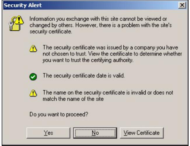
Figure 159 Security Alert Dialog Box (Internet Explorer)
15.4.2 Netscape Navigator Warning Messages
When you attempt to access the ZyXEL Device HTTPS server, a Website Certified by an Unknown Authority screen pops up asking if you trust the server certificate. Click Examine Certificate if you want to verify that the certificate is from the ZyXEL Device.
If Accept this certificate temporarily for this session is selected, then click OK to continue in Netscape.
Select Accept this certificate permanently to import the ZyXEL Device's certificate into the SSL client.
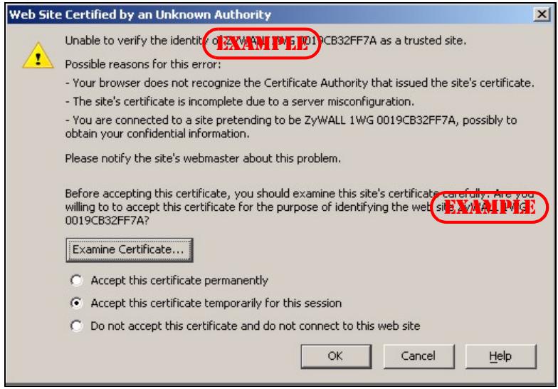
Figure 160 Security Certificate 1 (Netscape)
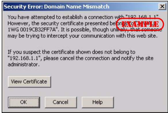
Figure 161 Security Certificate 2 (Netscape)
15.4.3 Avoiding the Browser Warning Messages
The following describes the main reasons that your browser displays warnings about the ZyXEL Device's HTTPS server certificate and what you can do to avoid seeing the warnings.
-
The issuing certificate authority of the ZyXEL Device's HTTPS server certificate is not one of the browser's trusted certificate authorities. The issuing certificate authority of the ZyXEL Device's factory default certificate is the ZyXEL Device itself since the certificate is a self-signed certificate.
-
For the browser to trust a self-signed certificate, import the self-signed certificate into your operating system as a trusted certificate.
-
To have the browser trust the certificates issued by a certificate authority, import the certificate authority's certificate into your operating system as a trusted certificate. Refer to Appendix F on page 403 for details.
-
The actual IP address of the HTTPS server (the IP address of the ZyXEL Device's port that you are trying to access) does not match the common name specified in the ZyXEL Device's HTTPS server certificate that your browser received. Do the following to check the common name specified in the certificate that your ZyXEL Device sends to HTTPS clients.
2a Click REMOTE MGMT. Write down the name of the certificate displayed in the Server Certificate field.
2b Click CERTIFICATES. Find the certificate and check its Subject column. CN stands for certificate's common name (see Figure 164 on page 266 for an example).
Use this procedure to have the ZyXEL Device use a certificate with a common name that matches the ZyXEL Device's actual IP address. You cannot use this procedure if you need to access the WAN port and it uses a dynamically assigned IP address.
2a Create a new certificate for the ZyXEL Device that uses the IP address (of the ZyXEL Device's port that you are trying to access) as the certificate's common name. For example, to use HTTPS to access a LAN port with IP address 192.168.1.1, create a certificate that uses 192.168.1.1 as the common name.
2b Go to the remote management WWW screen and select the newly created certificate in the Server Certificate field. Click Apply.
15.4.4 Login Screen
After you accept the certificate, the ZyXEL Device login screen appears. The lock displayed in the bottom right of the browser status bar denotes a secure connection.
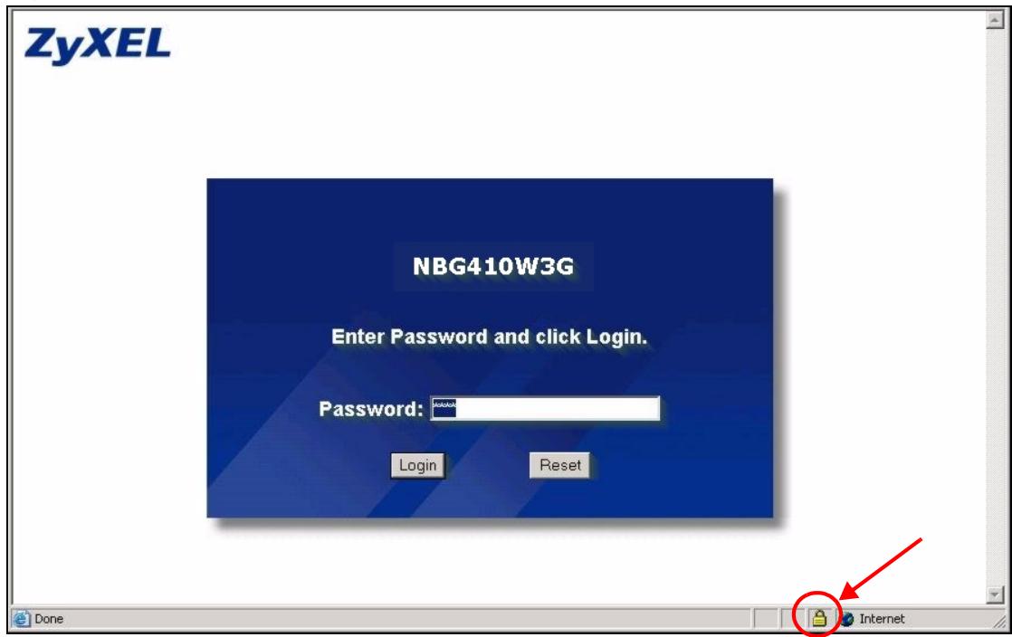
Figure 162 Example: Lock Denoting a Secure Connection
Click Login and you then see the next screen.
The factory default certificate is a common default certificate for all ZyXEL Device models.
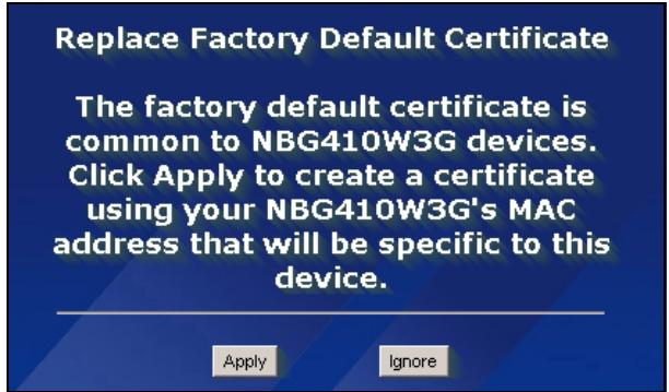
Figure 163 Replace Certificate
Click Apply in the Replace Certificate screen to create a certificate using your ZyXEL Device's MAC address that will be specific to this device. Click CERTIFICATES to open the My Certificates screen. You will see information similar to that shown in the following figure.
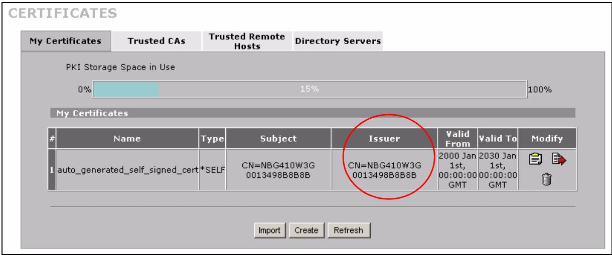
Figure 164 Device-specific Certificate
Click Ignore in the Replace Certificate screen to use the common ZyXEL Device certificate. You will then see this information in the My Certificates screen.
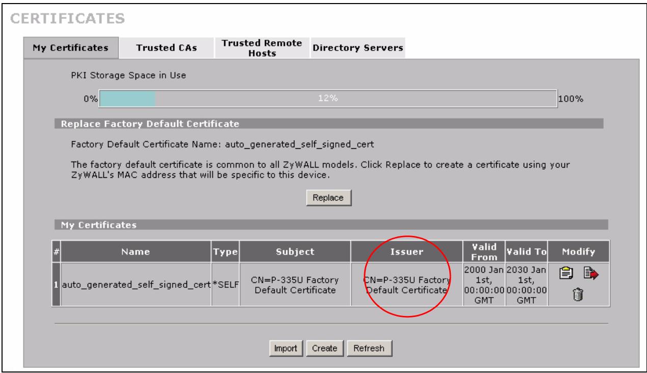
Figure 165 Common ZyXEL Device Certificate
15.5 SSH
You can use SSH (Secure SHell) to securely access the ZyXEL Device's command line interface. Specify which interfaces allow SSH access and from which IP address the access can come.
Unlike Telnet or FTP, which transmit data in plaintext (clear or unencrypted text), SSH is a secure communication protocol that combines authentication and data encryption to provide secure encrypted communication between two hosts over an unsecured network. In the following figure, computer A on the Internet uses SSH to securely connect to the WAN port of the ZyXEL Device for a management session.
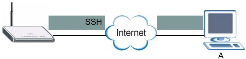
Figure 166 SSH Communication Over the WAN Example
15.6 How SSH Works
The following table summarizes how a secure connection is established between two remote hosts.
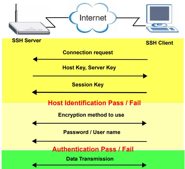
Figure 167 How SSH Works
1 Host Identification
The SSH client sends a connection request to the SSH server. The server identifies itself with a host key. The client encrypts a randomly generated session key with the host key and server key and sends the result back to the server.
The client automatically saves any new server public keys. In subsequent connections, the server public key is checked against the saved version on the client computer.
2 Encryption Method
Once the identification is verified, both the client and server must agree on the type of encryption method to use.
3 Authentication and Data Transmission
After the identification is verified and data encryption activated, a secure tunnel is established between the client and the server. The client then sends its authentication information (user name and password) to the server to log in to the server.
15.7 SSH Implementation on the ZyXEL Device
Your ZyXEL Device supports SSH version 1.5 using RSA authentication and three encryption methods (DES, 3DES and Blowfish). The SSH server is implemented on the ZyXEL Device for remote management and file transfer on port 22. Only one SSH connection is allowed at a time.
15.7.1 Requirements for Using SSH
You must install an SSH client program on a client computer (Windows or Linux operating system) that is used to connect to the ZyXEL Device over SSH.
15.8 Configuring SSH
Click ADVANCED > REMOTE MGMT > SSH to change your ZyXEL Device's Secure Shell settings.

It is recommended that you disable Telnet and FTP when you configure SSH for secure connections.
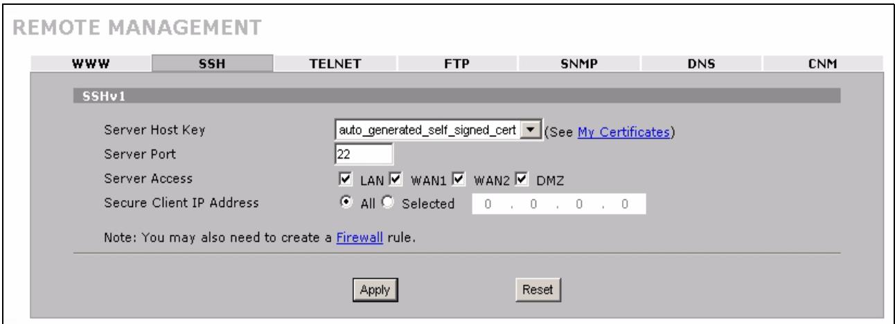
Figure 168 ADVANCED > REMOTE MGMT > SSH
The following table describes the labels in this screen.
Table 77 ADVANCED > REMOTE MGMT > SSH
| LABEL | DESCRIPTION |
| Server Host Key | Select the certificate whose corresponding private key is to be used to identify the ZyXEL Device for SSH connections. You must have certificates already configured in the My Certificates screen (Click My Certificates and see Chapter 11 on page 195 for details). |
| Server Port | You may change the server port number for a service if needed, however you must use the same port number in order to use that service for remote management. |
| Server Access | Select the interface(s) through which a computer may access the ZyXEL Device using this service. |
| Secure Client IP Address | A secure client is a “trusted” computer that is allowed to communicate with the ZyXEL Device using this service. Select All to allow any computer to access the ZyXEL Device using this service. Choose Selected to just allow the computer with the IP address that you specify to access the ZyXEL Device using this service. |
| Apply | Click Apply to save your customized settings and exit this screen. |
| Reset | Click Reset to begin configuring this screen afresh. |
15.9 Secure Telnet Using SSH Examples
This section shows two examples using a command interface and a graphical interface SSH client program to remotely access the ZyXEL Device. The configuration and connection steps are similar for most SSH client programs. Refer to your SSH client program user's guide.
15.9.1 Example 1: Microsoft Windows
This section describes how to access the ZyXEL Device using the Secure Shell Client program.
1 Launch the SSH client and specify the connection information (IP address, port number or device name) for the ZyXEL Device.
2 Configure the SSH client to accept connection using SSH version 1.
3 A window displays prompting you to store the host key in your computer. Click Yes to continue.
Figure 169 SSH Example 1: Store Host Key
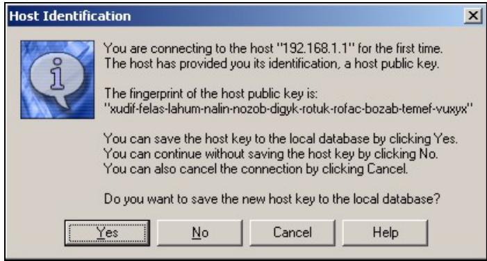
Figure 170 SSH Example 2: Test
Enter the password to log in to the ZyXEL Device. The CLI main menu displays next.
15.9.2 Example 2: Linux
This section describes how to access the ZyXEL Device using the OpenSSH client program that comes with most Linux distributions.
1 Test whether the SSH service is available on the ZyXEL Device.
Enter "telnet 192.168.1.1 22" at a terminal prompt and press [ENTER]. The computer attempts to connect to port 22 on the ZyXEL Device (using the default IP address of 192.168.1.1).
A message displays indicating the SSH protocol version supported by the ZyXEL Device.
$ telnet 192.168.1.1 22
Trying 192.168.1.1...
Connected to 192.168.1.1.
Escape character is '^」'.
SSH-1.5-1.0.0
2 Enter "ssh -1 192.168.1.1". This command forces your computer to connect to the ZyXEL Device using SSH version 1. If this is the first time you are connecting to the ZyXEL Device using SSH, a message displays prompting you to save the host information of the ZyXEL Device. Type "yes" and press [ENTER].
Then enter the password to log in to the ZyXEL Device.
Figure 171 SSH Example 2: Log in
$ ssh -1 192.168.1.1
The authenticity of host '192.168.1.1' (192.168.1.1)' can't be
established.
RSA1 key fingerprint is
21:6c:07:25:7e:f4:75:80:ec:af:bd:d4:3d:80:53:d1.
Are you sure you want to continue connecting (yes/no)? yes
Warning: Permanently added '192.168.1.1' (RSA1) to the list of
known hosts.
Administrator@192.168.1.1's password:
3 The CLI main menu displays next.
15.10 Secure FTP Using SSH Example
This section shows an example on file transfer using the OpenSSH client program. The configuration and connection steps are similar for other SSH client programs. Refer to your SSH client program user's guide.
1 Enter "sftp -1 192.168.1.1". This command forces your computer to connect to the ZyXEL Device for secure file transfer using SSH version 1. If this is the first time you are connecting to the ZyXEL Device using SSH, a message displays prompting you to save the host information of the ZyXEL Device. Type "yes" and press [ENTER].
2 Enter the password to login to the ZyXEL Device.
3 Use the "put" command to upload a new firmware to the ZyXEL Device.

Figure 172 Secure FTP: Firmware Upload Example
15.11 Telnet
You can use Telnet to access the ZyXEL Device's command line interface. Specify which interfaces allow Telnet access and from which IP address the access can come.
15.12 Configuring TELNET
Click ADVANCED > REMOTE MGMT > TELNET to open the following screen. Use this screen to specify which interfaces allow Telnet access and from which IP address the access can come.

It is recommended that you disable Telnet and FTP when you configure SSH for secure connections.
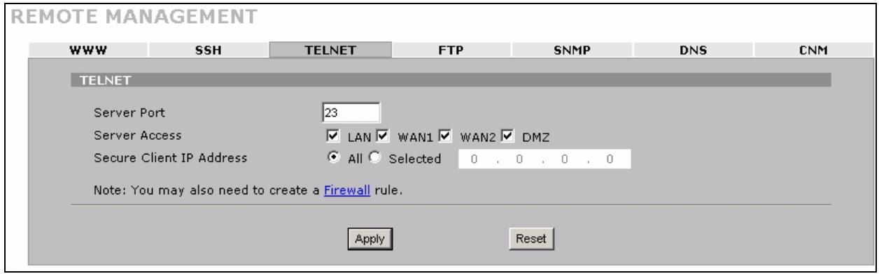
Figure 173 ADVANCED >REMOTE MGMT > Telnet
The following table describes the labels in this screen.
Table 78 ADVANCED > REMOTE MGMT > Telnet
| LABEL | DESCRIPTION |
| Server Port | You may change the server port number for a service if needed, however you must use the same port number in order to use that service for remote management. |
| Server Access | Select the interface(s) through which a computer may access the ZyXEL Device using this service. |
| Secure Client IP Address | A secure client is a “trusted” computer that is allowed to communicate with the ZyXEL Device using this service. Select All to allow any computer to access the ZyXEL Device using this service. Choose Selected to just allow the computer with the IP address that you specify to access the ZyXEL Device using this service. |
| Apply | Click Apply to save your customized settings and exit this screen. |
| Reset | Click Reset to begin configuring this screen afresh. |
15.13 FTP
You can use FTP (File Transfer Protocol) to upload and download the ZyXEL Device's firmware and configuration files, please see the User's Guide chapter on firmware and configuration file maintenance for details. To use this feature, your computer must have an FTP client.
To change your ZyXEL Device's FTP settings, click ADVANCED > REMOTE MGMT > FTP. The screen appears as shown. Use this screen to specify which interfaces allow FTP access and from which IP address the access can come.

It is recommended that you disable Telnet and FTP when you configure SSH for secure connections.
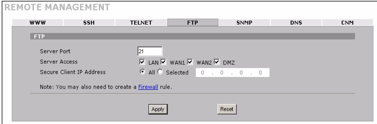
Figure 174 ADVANCED > REMOTE MGMT > FTP
The following table describes the labels in this screen.
Table 79 ADVANCED > REMOTE MGMT > FTP
| LABEL | DESCRIPTION |
| Server Port | You may change the server port number for a service if needed, however you must use the same port number in order to use that service for remote management. |
| Server Access | Select the interface(s) through which a computer may access the ZyXEL Device using this service. |
| Secure Client IP Address | A secure client is a “trusted” computer that is allowed to communicate with the ZyXEL Device using this service. Select All to allow any computer to access the ZyXEL Device using this service. Choose Selected to just allow the computer with the IP address that you specify to access the ZyXEL Device using this service. |
| Apply | Click Apply to save your customized settings. |
| Reset | Click Reset to begin configuring this screen afresh. |
15.14 SNMP
Simple Network Management Protocol is a protocol used for exchanging management information between network devices. SNMP is a member of the TCP/IP protocol suite. Your ZyXEL Device supports SNMP agent functionality, which allows a manager station to manage and monitor the ZyXEL Device through the network. The ZyXEL Device supports SNMP version one (SNMPv1). The next figure illustrates an SNMP management operation.

SNMP is only available if TCP/IP is configured.
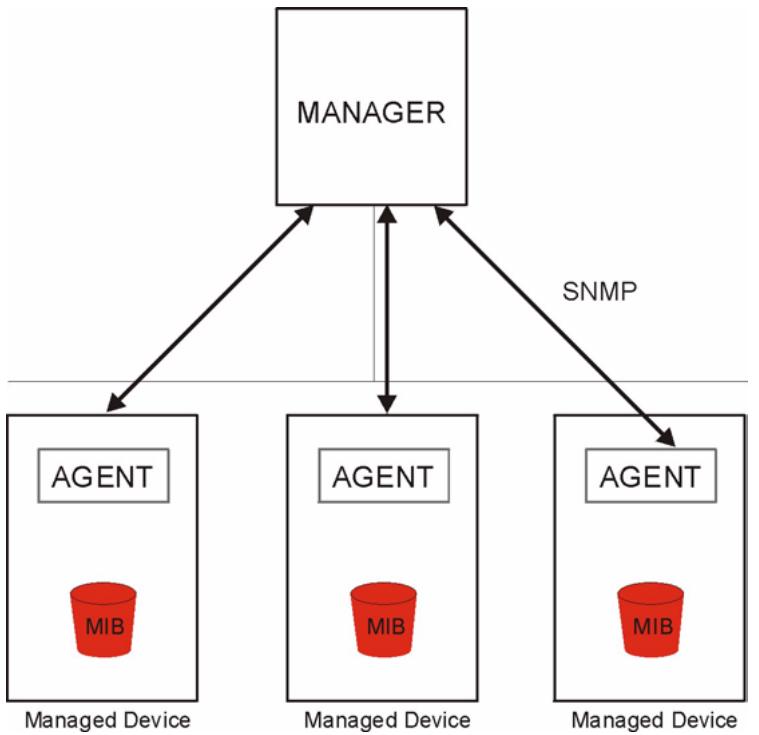
Figure 175 SNMP Management Model
An SNMP managed network consists of two main types of component: agents and a manager.
An agent is a management software module that resides in a managed device (the ZyXEL Device). An agent translates the local management information from the managed device into a form compatible with SNMP. The manager is the console through which network administrators perform network management functions. It executes applications that control and monitor managed devices.
The managed devices contain object variables/managed objects that define each piece of information to be collected about a device. Examples of variables include such as number of packets received, node port status etc. A Management Information Base (MIB) is a collection of managed objects. SNMP allows a manager and agents to communicate for the purpose of accessing these objects.
SNMP itself is a simple request/response protocol based on the manager/agent model. The manager issues a request and the agent returns responses using the following protocol operations:
- Get - Allows the manager to retrieve an object variable from the agent.
- GetNext - Allows the manager to retrieve the next object variable from a table or list within an agent. In SNMPv1, when a manager wants to retrieve all elements of a table from an agent, it initiates a Get operation, followed by a series of GetNext operations.
- Set - Allows the manager to set values for object variables within an agent.
- Trap - Used by the agent to inform the manager of some events.
15.14.1 Supported MIBs
The ZyXEL Device supports MIB II that is defined in RFC-1213 and RFC-1215. The focus of the MIBs is to let administrators collect statistical data and monitor status and performance.
15.14.2 SNMP Traps
The ZyXEL Device will send traps to the SNMP manager when any one of the following events occurs:
Table 80 SNMP Traps
| TRAP # | TRAP NAME | DESCRIPTION |
| 0 | coldStart (defined in RFC-1215) | A trap is sent after booting (power on). |
| 1 | warmStart (defined in RFC-1215) | A trap is sent after booting (software reboot). |
| 4 | authenticationFailure (defined in RFC-1215) | A trap is sent to the manager when receiving any SNMP get or set requirements with the wrong community (password). |
| 6 | whyReboot (defined in ZYXEL-MIB) | A trap is sent with the reason of restart before rebooting when the system is going to restart (warm start). |
| 6a | For intentional reboot : | A trap is sent with the message "System reboot by user!" if reboot is done intentionally, (for example, download new files, Cl command "sys reboot", etc.). |
| 6b | For fatal error : | A trap is sent with the message of the fatal code if the system reboots because of fatal errors. |
15.14.3 REMOTE MANAGEMENT: SNMP
To change your ZyXEL Device's SNMP settings, click ADVANCED > REMOTE MGMT > SNMP. The screen appears as shown.
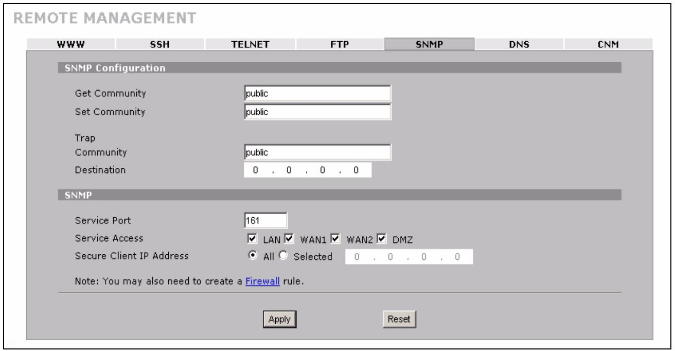
Figure 176 ADVANCED > REMOTE MGMT > SNMP
The following table describes the labels in this screen.
Table 81 ADVANCED > REMOTE MGMT > SNMP
| LABEL | DESCRIPTION |
| SNMP Configuration | |
| Get Community | Enter the Get Community, which is the password for the incoming Get and GetNext requests from the management station. The default is public and allows all requests. |
| Set Community | Enter the Set community, which is the password for incoming Set requests from the management station. The default is public and allows all requests. |
| Trap | |
| Community | Type the trap community, which is the password sent with each trap to the SNMP manager. The default is public and allows all requests. |
| Destination | Type the IP address of the station to send your SNMP traps to. |
| SNMP | |
| Service Port | You may change the server port number for a service if needed, however you must use the same port number in order to use that service for remote management. |
| Service Access | Select the interface(s) through which a computer may access the ZyXEL Device using this service. |
| Secure Client IP Address | A secure client is a “trusted” computer that is allowed to communicate with the ZyXEL Device using this service. Select All to allow any computer to access the ZyXEL Device using this service. Choose Selected to just allow the computer with the IP address that you specify to access the ZyXEL Device using this service. |
| Apply | Click Apply to save your customized settings. |
| Reset | Click Reset to begin configuring this screen afresh. |
15.15 DNS
Use DNS (Domain Name System) to map a domain name to its corresponding IP address and vice versa. Refer to Chapter 6 on page 111 for more information.
Click ADVANCED > REMOTE MGMT > DNS to change your ZyXEL Device's DNS settings. Use this screen to set from which IP address the ZyXEL Device will accept DNS queries and on which interface it can send them your ZyXEL Device's DNS settings.
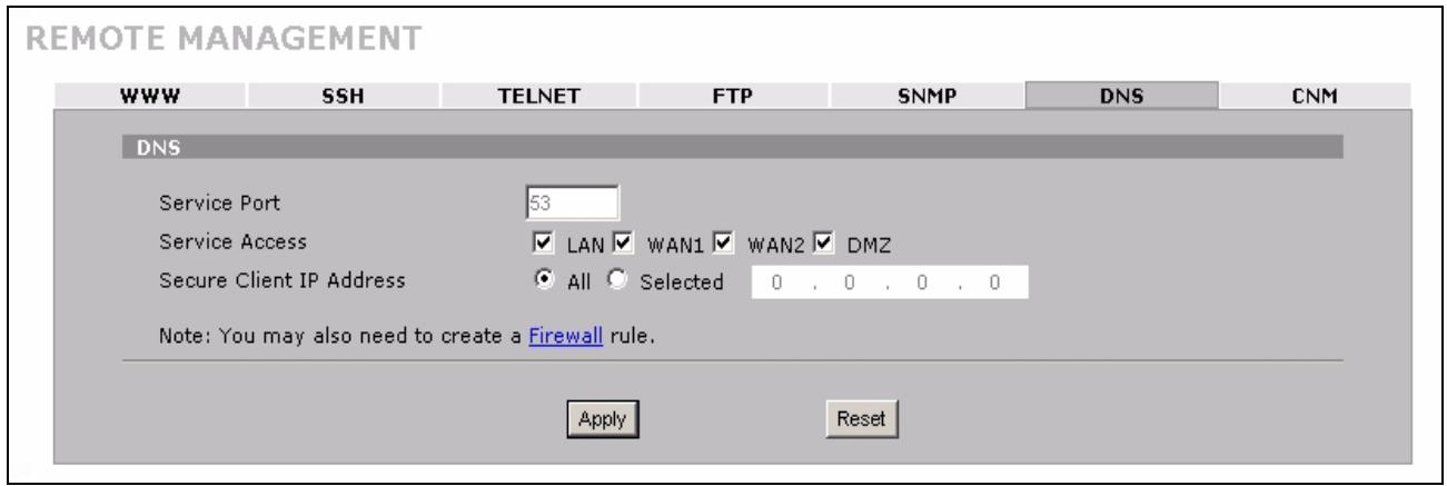
Figure 177 ADVANCED > REMOTE MGMT > DNS
The following table describes the labels in this screen.
Table 82 ADVANCED > REMOTE MGMT > DNS
| LABEL | DESCRIPTION |
| Server Port | The DNS service port number is 53 and cannot be changed here. |
| Service Access | Select the interface(s) through which a computer may send DNS queries to the ZyXEL Device. |
| Secure Client IP Address | A secure client is a “trusted” computer that is allowed to send DNS queries to the ZyXEL Device. Select All to allow any computer to send DNS queries to the ZyXEL Device. Choose Selected to just allow the computer with the IP address that you specify to send DNS queries to the ZyXEL Device. |
| Apply | Click Apply to save your customized settings. |
| Reset | Click Reset to begin configuring this screen afresh. |
15.16 Introducing Vantage CNM
Vantage CNM (Centralized Network Management) is a browser-based global management solution that allows an administrator from any location to easily configure, manage, monitor and troubleshoot ZyXEL devices located worldwide. See the Vantage CNM User's Guide for details.
If you allow your ZyXEL Device to be managed by the Vantage CNM server, then you should not do any configurations directly to the ZyXEL Device (using either the web configurator or commands) without notifying the Vantage CNM administrator.
15.17 Configuring CNM
Vantage CNM is disabled on the device by default. Click ADVANCED > REMOTE MGMT > CNM to configure your device's Vantage CNM settings.
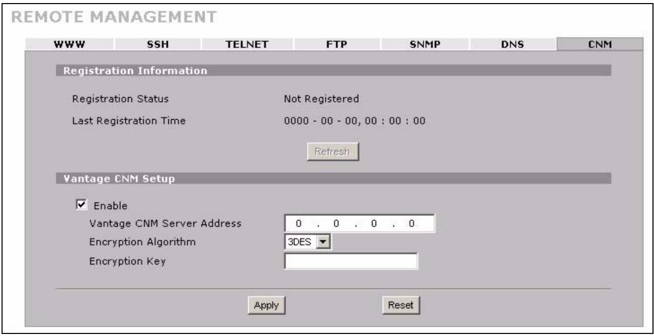
Figure 178 ADVANCED > REMOTE MGMT > CNM
The following table describes the labels in this screen.
Table 83 ADVANCED > REMOTE MGMT > CNM
| LABEL | DESCRIPTION |
| Registration Information | |
| Registration Status | This read only field displays Not Registered when Enable is not selected. It displays Registering when the ZyXEL Device first connects with the Vantage CNM server and then Registered after it has been successfully registered with the Vantage CNM server. It will continue to display Registering until it successfully registers with the Vantage CNM server. It will not be able to register with the Vantage CNM server if: The Vantage CNM server is down. The Vantage CNM server IP address is incorrect. The Vantage CNM server is behind a NAT router or firewall that does not forward packets through to the Vantage CNM server. The encryption algorithms and/or encryption keys do not match between the ZyXEL Device and the Vantage CNM server. |
| Last Registration Time | This field displays the last date (year-month-date) and time (hours-minutes-seconds) that the ZyXEL Device registered with the Vantage CNM server. It displays all zeroes if it has not yet registered with the Vantage CNM server. |
| Refresh | Click Refresh to update the registration status and last registration time. |
| Vantage CNM Setup | |
| Enable | Select this check box to allow Vantage CNM to manage your ZyXEL Device. |
| Vantage CNM Server Address | If the Vantage server is on the same subnet as the ZyXEL Device, enter the private or public IP address of the Vantage server. If the Vantage CNM server is on a different subnet to the ZyXEL Device, enter the public IP address of the Vantage server. If the Vantage CNM server is on a different subnet to the ZyXEL Device and is behind a NAT router, enter the WAN IP address of the NAT router here. |
| Encryption Algorithm | The Encryption Algorithm field is used to encrypt communications between the ZyXEL Device and the Vantage CNM server. Choose from None (no encryption), DES or 3DES. The Encryption Key field appears when you select DES or 3DES. The ZyXEL Device must use the same encryption algorithm as the Vantage CNM server. |
| Encryption Key | Type eight alphanumeric characters ("0" to "9", "a" to "z" or "A" to "Z") when you choose the DES encryption algorithm and 24 alphanumeric characters ("0" to "9", "a" to "z" or "A" to "Z") when you choose the 3DES encryption algorithm. The ZyXEL Device must use the same encryption key as the Vantage CNM server. |
| Apply | Click Apply to save your changes. |
| Reset | Click Reset to begin configuring this screen afresh. |
15.17.1 Additional Configuration for Vantage CNM
If you have NAT routers or firewalls between the ZyXEL Device and the Vantage CNM server, you must configure them to forward TCP ports 8080 (HTTP), 443 (HTTPS) and 20 and 21 (FTP). They must also forward UDP ports 1864 and 1865.
This chapter introduces the Universal Plug and Play feature.
16.1 Universal Plug and Play Overview
Universal Plug and Play (UPnP) is a distributed, open networking standard that uses TCP/IP for simple peer-to-peer network connectivity between devices. A UPnP device can dynamically join a network, obtain an IP address, convey its capabilities and learn about other devices on the network. In turn, a device can leave a network smoothly and automatically when it is no longer in use.
16.1.1 How Do I Know If I'm Using UPnP?
UPnP hardware is identified as an icon in the Network Connections folder (Windows XP). Each UPnP compatible device installed on your network will appear as a separate icon. Selecting the icon of a UPnP device will allow you to access the information and properties of that device.
16.1.2 NAT Traversal
UPnP NAT traversal automates the process of allowing an application to operate through NAT. UPnP network devices can automatically configure network addressing, announce their presence in the network to other UPnP devices and enable exchange of simple product and service descriptions. NAT traversal allows the following:
- Dynamic port mapping
- Learning public IP addresses
- Assigning lease times to mappings
Windows Messenger is an example of an application that supports NAT traversal and UPnP.
See Chapter 12 on page 225 for further information about NAT.
16.1.3 Cautions with UPnP
The automated nature of NAT traversal applications in establishing their own services and opening firewall ports may present network security issues. Network information and configuration may also be obtained and modified by users in some network environments.
When a UPnP device joins a network, it announces its presence with a multicast message. For security reasons, the ZyXEL Device allows multicast messages on the LAN only.
All UPnP-enabled devices may communicate freely with each other without additional configuration. Disable UPnP if this is not your intention.
16.1.4 UPnP and ZyXEL
ZyXEL has achieved UPnP certification from the Universal Plug and Play Forum UPnP™ Implementers Corp. (UIC). ZyXEL's UPnP implementation supports IGD 1.0 (Internet Gateway Device).
See the following sections for examples of installing and using UPnP.
16.2 Configuring UPnP
Click ADVANCED > UPnP to display the UPnP screen.
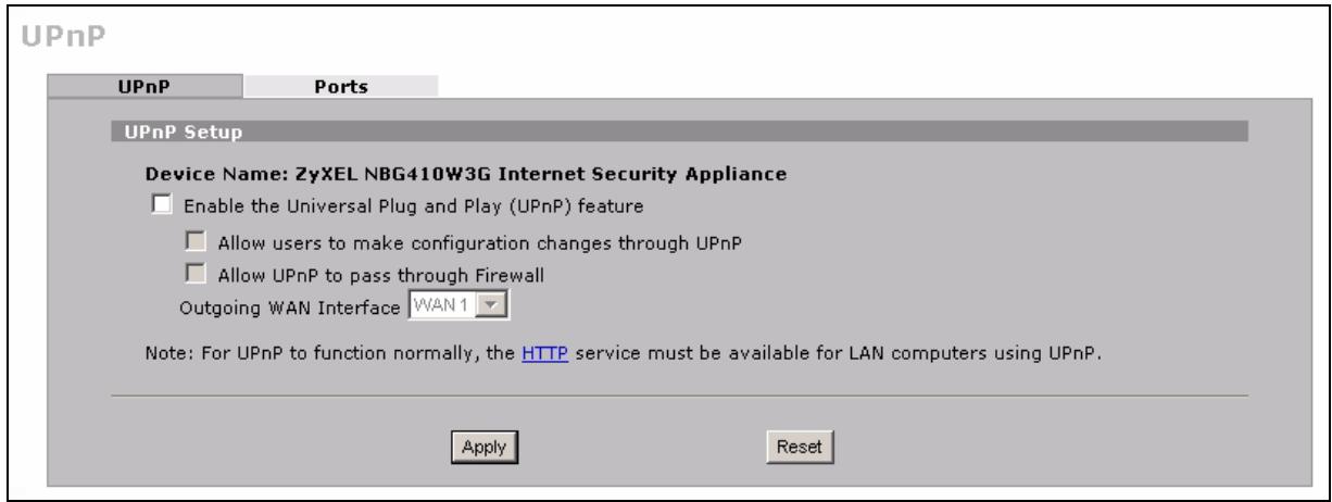
Figure 179 ADVANCED > UPnP
The following table describes the fields in this screen.
Table 84 ADVANCED > UPnP
| LABEL | DESCRIPTION |
| UPnP Setup | |
| Device Name | This identifies the ZyXEL device in UPnP applications. |
| Enable the Universal Plug and Play (UPnP) feature | Select this check box to activate UPnP. Be aware that anyone could use a UPnP application to open the web configurator's login screen without entering the ZyXEL Device's IP address (although you must still enter the password to access the web configurator). |
| Allow users to make configuration changes through UPnP | Select this check box to allow UPnP-enabled applications to automatically configure the ZyXEL Device so that they can communicate through the ZyXEL Device, for example by using NAT traversal, UPnP applications automatically reserve a NAT forwarding port in order to communicate with another UPnP enabled device; this eliminates the need to manually configure port forwarding for the UPnP enabled application. |
| Allow UPnP to pass through Firewall | Select this check box to allow traffic from UPnP-enabled applications to bypass the firewall.Clear this check box to have the firewall block all UPnP application packets (for example, MSN packets). |
Table 84 ADVANCED > UPnP
| LABEL | DESCRIPTION |
| Outgoing WAN Interface | Select through which WAN port you want to send out traffic from UPnP-enabled applications. If the WAN port you select loses its connection, the ZyXEL Device attempts to use the other WAN port. If the other WAN port also does not work, the ZyXEL Device drops outgoing packets from UPnP-enabled applications. |
| Apply | Click Apply to save your changes. |
| Reset | Click Reset to begin configuring this screen afresh. |
16.3 Displaying UPnP Port Mapping
Click ADVANCED > UPnP > Ports to display the UPnP Ports screen. Use this screen to view the NAT port mapping rules that UPnP creates on the ZyXEL Device.
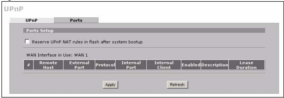
Figure 180 ADVANCED > UPnP > Ports
The following table describes the labels in this screen.
Table 85 ADVANCED > UPnP > Ports
| LABEL | DESCRIPTION |
| Reserve UPnP NAT rules in flash after system bootup | Select this check box to have the ZyXEL Device retain UPnP created NAT rules even after restarting. If you use UPnP and you set a port on your computer to be fixed for a specific service (for example FTP for file transfers), this option allows the ZyXEL Device to keep a record when your computer uses UPnP to create a NAT forwarding rule for that service. |
| WAN Interface in Use | This field displays through which WAN interface the ZyXEL Device is currently sending out traffic from UPnP-enabled applications. This field displays None when UPnP is disabled or neither of the WAN ports has a connection. |
| The following read-only table displays information about the UPnP-created NAT mapping rule entries in the ZyXEL Device's NAT routing table. | |
| # | This is the index number of the UPnP-created NAT mapping rule entry. |
| Remote Host | This field displays the source IP address (on the WAN) of inbound IP packets. Since this is often a wildcard, the field may be blank. When the field is blank, the ZyXEL Device forwards all traffic sent to the External Port on the WAN interface to the Internal Client on the Internal Port. When this field displays an external IP address, the NAT rule has the ZyXEL Device forward inbound packets to the Internal Client from that IP address only. |
| External Port | This field displays the port number that the ZyXEL Device “listens” on (on the WAN port) for connection requests destined for the NAT rule’s Internal Port and Internal Client. The ZyXEL Device forwards incoming packets (from the WAN) with this port number to the Internal Client on the Internal Port (on the LAN). If the field displays “0”, the ZyXEL Device ignores the Internal Port value and forwards requests on all external port numbers (that are otherwise unmapped) to the Internal Client. |
| Protocol | This field displays the protocol of the NAT mapping rule (TCP or UDP). |
| Internal Port | This field displays the port number on the Internal Client to which the ZyXEL Device should forward incoming connection requests. |
| Internal Client | This field displays the DNS host name or IP address of a client on the LAN. Multiple NAT clients can use a single port simultaneously if the internal client field is set to 255.255.255.255 for UDP mappings. |
| Enabled | This field displays whether or not this UPnP-created NAT mapping rule is turned on. The UPnP-enabled device that connected to the ZyXEL Device and configured the UPnP-created NAT mapping rule on the ZyXEL Device determines whether or not the rule is enabled. |
| Description | This field displays a text explanation of the NAT mapping rule. |
| Lease Duration | This field displays a dynamic port-mapping rule’s time to live (in seconds). It displays “0” if the port mapping is static. |
| Apply | Click Apply to save your changes. |
| Refresh | Click Refresh update the screen’s table. |
16.4 Installing UPnP in Windows Example
This section shows how to install UPnP in Windows Me and Windows XP.
16.4.1 Installing UPnP in Windows Me
Follow the steps below to install UPnP in Windows Me.
1 Click Start, Settings and Control Panel. Double-click Add/Remove Programs.
2 Click on the Windows Setup tab and select Communication in the Components selection box. Click Details.
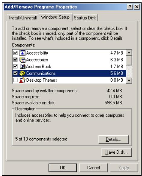
3 In the Communications window, select the Universal Plug and Play check box in the Components selection box.
4 Click OK to go back to the Add/ Remove Programs Properties window and click Next.
5 Restart the computer when prompted.
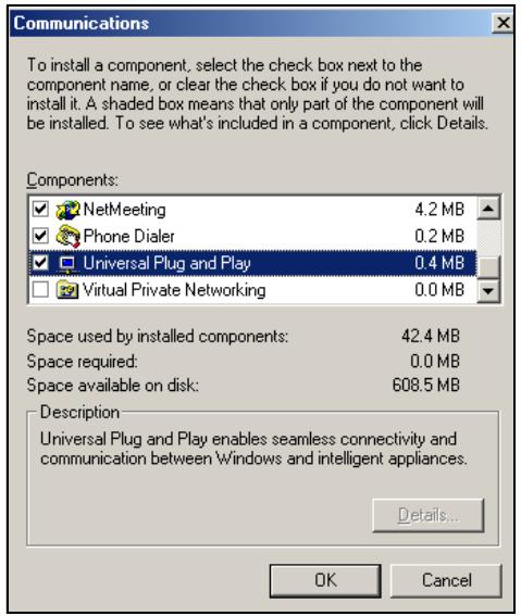
16.4.2 Installing UPnP in Windows XP
Follow the steps below to install UPnP in Windows XP.
1 Click Start, Settings and Control Panel.
2 Double-click Network Connections.
3 In the Network Connections window, click Advanced in the main menu and select Optional Networking Components ....
The Windows Optional Networking Components Wizard window displays.
4 Select Networking Service in the Components selection box and click Details.
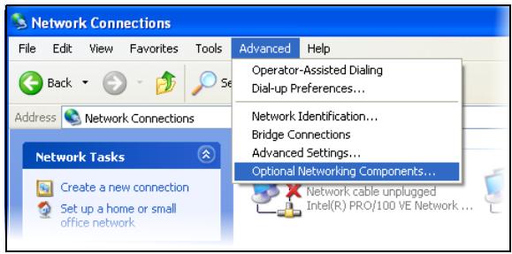
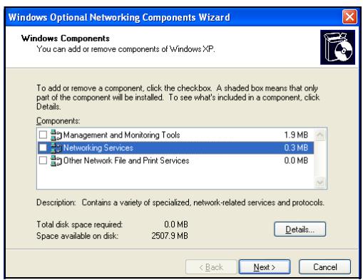
5 In the Networking Services window, select the Universal Plug and Play check box.
6 Click OK to go back to the Windows Optional Networking Component Wizard window and click Next.
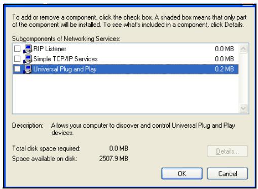
16.5 Using UPnP in Windows XP Example
This section shows you how to use the UPnP feature in Windows XP. You must already have UPnP installed in Windows XP and UPnP activated on the ZyXEL device.
Make sure the computer is connected to a LAN port of the ZyXEL device. Turn on your computer and the ZyXEL device.
16.5.1 Auto-discover Your UPnP-enabled Network Device
1 Click Start and Control Panel. Double-click Network Connections. An icon displays under Internet Gateway.
2 Right-click the icon and select Properties.
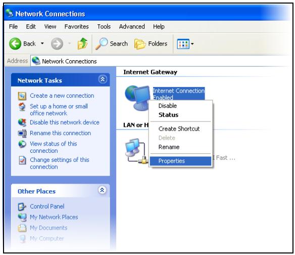
3 In the Internet Connection Properties window, click Settings to see the port mappings that were automatically created.
You may edit or delete the port mappings or click Add to manually add port mappings.
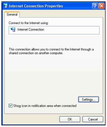
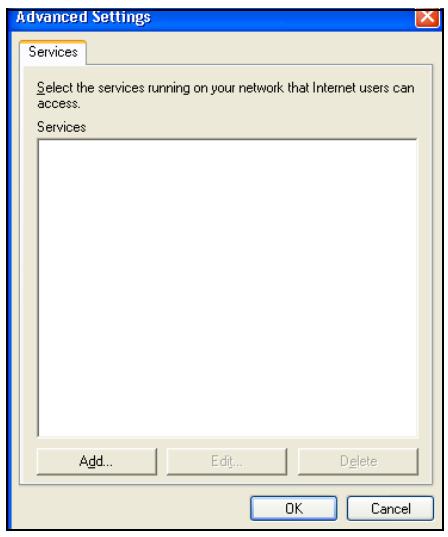
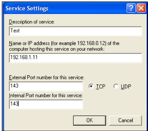

When the UPnP-enabled device is disconnected from your computer, all port mappings will be deleted automatically.
4 Select the Show icon in notification area when connected check box and click OK. An icon displays in the system tray.
5 Double-click the icon to display your current Internet connection status.
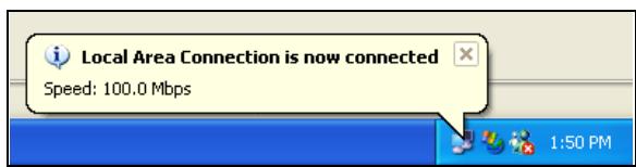

16.5.2 Web Configurator Easy Access
With UPnP, you can access the web-based configurator on the ZyXEL device without finding out the IP address of the ZyXEL device first. This is helpful if you do not know the IP address of the ZyXEL device.
Follow the steps below to access the web configurator.
1 Click Start and then Control Panel.
2 Double-click Network Connections.
3 Select My Network Places under Other Places.
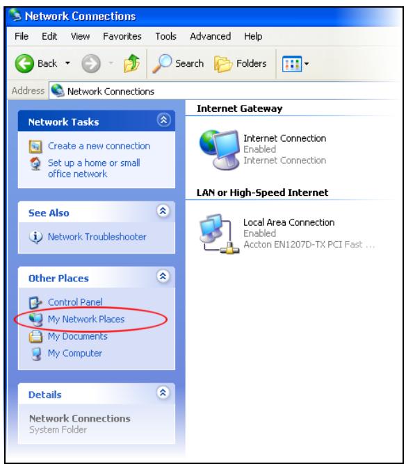
4 An icon with the description for each UPnP-enabled device displays under Local Network.
5 Right-click the icon for your ZyXEL device and select Invoke. The web configurator login screen displays.
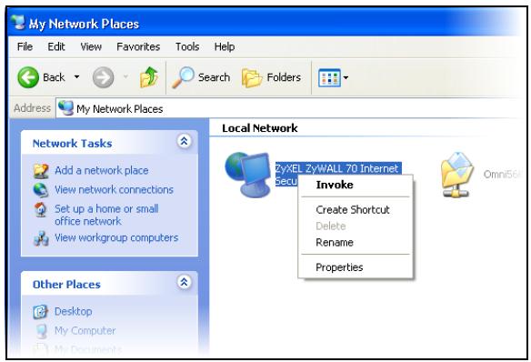
6 Right-click the icon for your ZyXEL device and select Properties. A properties window displays with basic information about the ZyXEL device.
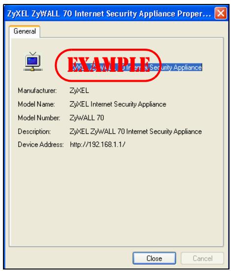
Custom Application
This chapter covers how to set the ZyXEL Device's to monitor custom port numbers for specific applications.
17.1 Custom Application
Use custom application to have the ZyXEL Device's ALG feature monitor traffic on custom ports, in addition to the default ports.
By default, these ZyXEL Device features monitor traffic for the following protocols on these port numbers.
FTP:21
SIP: 5060
H.323:1720
- SMTP: 25
POP3:110
- HTTP: 80

Changes in the Custom APP screen do not apply to the firewall.
17.2 Custom Application Configuration
Click ADVANCED > Custom APP to open the Custom Application screen.

This screen only specifies what port numbers the ZyXEL Device checks for specific protocol traffic. Use other screens to enable or disable the monitoring of the protocol traffic.
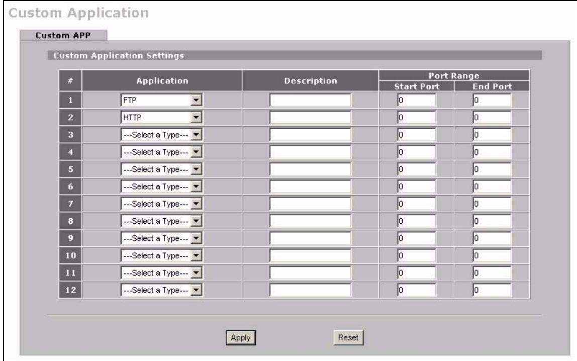
Figure 181 ADVANCED > Custom APP
The following table describes the labels in this screen.
Table 86 ADVANCED > Custom APP
| LABEL | DESCRIPTION |
| Application | Select the application for which you want the ZyXEL Device to monitor specific ports. You can use the same application in more than one entry. To remove an entry, select Select a Type. |
| Description | Enter information about the reason for monitoring custom port numbers for this protocol. |
| Start Port | Enter the starting port for the range that the ZyXEL Device is to monitor for this application. If you are only entering a single port number, enter it here. |
| End Port | Enter the ending port for the range that the ZyXEL Device is to monitor for this application. |
| Apply | Click Apply to save your changes. |
| Reset | Click Reset to begin configuring this screen afresh. |
ALG Screen
This chapter covers how to use the ZyXEL Device's ALG feature to allow certain applications to pass through the ZyXEL Device.
18.1 ALG Introduction
An Application Layer Gateway (ALG) manages a specific protocol (such as SIP, H.323 or FTP) at the application layer. The ZyXEL Device can function as an ALG to allow certain NAT un-friendly applications (such as SIP) to operate properly through the ZyXEL Device.
Some applications cannot operate through NAT (are NAT un-friendly) because they embed IP addresses and port numbers in their packets' data payload. The ZyXEL Device examines and uses IP address and port number information embedded in the data stream. When a device behind the ZyXEL Device uses an application for which the ZyXEL Device has ALG service enabled, the ZyXEL Device translates the device's private IP address inside the data stream to a public IP address. It also records session port numbers and dynamically creates implicit NAT port forwarding and firewall rules for the application's traffic to come in from the WAN to the LAN.
18.1.1 ALG and NAT
The ZyXEL Device dynamically creates an implicit NAT session for the application's traffic from the WAN to the LAN.
The ALG on the ZyXEL Device supports all NAT mapping types, including One to One, Many to One, Many to Many Overload and Many One to One.
18.1.2 ALG and the Firewall
The ZyXEL Device uses the dynamic port that the session uses for data transfer in creating an implicit temporary firewall rule for the session's traffic. The firewall rule only allows the session's traffic to go through in the direction that the ZyXEL Device determines from its inspection of the data payload of the application's packets. The firewall rule is automatically deleted after the application's traffic has gone through.
18.1.3 ALG and Multiple WAN
When the ZyXEL Device has two WAN interfaces and uses the second highest priority WAN interfaces as a back up, traffic cannot pass through when the primary WAN connection fails. The ZyXEL Device does not automatically change the connection to the secondary WAN interfaces.
If the primary WAN connection fails, the client needs to re-initialize the connection through the secondary WAN interfaces to have the connection go through the secondary WAN interfaces.
18.2 FTP
File Transfer Protocol (FTP) is an Internet file transfer service that operates on the Internet and over TCP/IP networks. A system running the FTP server accepts commands from a system running an FTP client. The service allows users to send commands to the server for uploading and downloading files. The FTP ALG allows TCP packets with a port 21 destination to pass through. If the FTP server is located on the LAN, you must also configure NAT port forwarding and firewall rules if you want to allow access to the server from the WAN.
18.3 H.323
H.323 is a standard teleconferencing protocol suite that provides audio, data and video conferencing. It allows for real-time point-to-point and multipoint communication between client computers over a packet-based network that does not provide a guaranteed quality of service. NetMeeting uses H.323.
18.4 RTP
When you make a VoIP call using H.323 or SIP, the RTP (Real time Transport Protocol) is used to handle voice data transfer. See RFC 1889 for details on RTP.
18.4.1 H.323 ALG Details
- The H.323 ALG supports peer-to-peer H.323 calls.
- The H.323 ALG handles H.323 calls that go through NAT or that the ZyXEL Device routes. You can also make other H.323 calls that do not go through NAT or routing. Examples would be calls between LAN IP addresses that are on the same subnet.
- The H.323 ALG allows calls to go out through NAT. For example, you could make a call from a private IP address on the LAN to a peer device on the WAN.
- You must configure the firewall and port forwarding to allow incoming (peer-to-peer) calls from the WAN to a private IP address on the LAN or DMZ. The following example shows H.323 signaling (1) and audio (2) sessions between H.323 devices A and B.
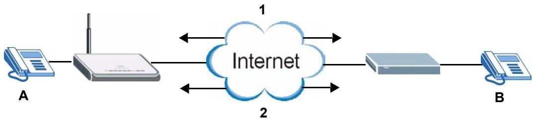
Figure 182 H.323 ALG Example
- With multiple WAN IP addresses on the ZyXEL Device, you can configure different firewall and port forwarding rules to allow incoming calls from each WAN IP address to go to a specific IP address on the LAN or DMZ.
For example, you configure firewall and port forwarding rules to allow LAN IP address A to receive calls through public WAN IP address 1. You configure different firewall and port forwarding rules to allow LAN IP address B to receive calls through public WAN IP address 2.
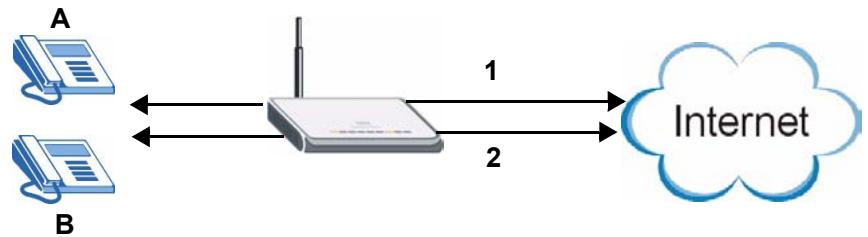
Figure 183 H.323 with Multiple WAN IP Addresses
- The H.323 ALG operates on TCP packets with a port 1720 destination.
- The ZyXEL Device allows H.323 audio connections.
18.5 SIP
The Session Initiation Protocol (SIP) is an application-layer control (signaling) protocol that handles the setting up, altering and tearing down of voice and multimedia sessions over the Internet. SIP is used in VoIP (Voice over IP), the sending of voice signals over the Internet Protocol.
SIP signaling is separate from the media for which it handles sessions. The media that is exchanged during the session can use a different path from that of the signaling. SIP handles telephone calls and can interface with traditional circuit-switched telephone networks.
18.5.1 STUN
STUN (Simple Traversal of User Datagram Protocol (UDP) through Network Address Translators) allows the VoIP device to find the presence and types of NAT routers and/or firewalls between it and the public Internet. STUN also allows the VoIP device to find the public IP address that NAT assigned, so the VoIP device can embed it in the SIP data stream. See RFC 3489 for details on STUN. You do not need to use STUN for devices behind the ZyXEL Device if you enable the SIP ALG.
18.5.2 SIP ALG Details
- SIP clients can be connected to the LAN or DMZ. A SIP server must be on the WAN.
- You can make and receive calls between the LAN and the WAN, between the DMZ and the WAN. You cannot make a call between the LAN and the LAN, between the LAN and the DMZ, between the DMZ and the DMZ, and so on.
- The SIP ALG allows UDP packets with a port 5060 destination to pass through.
- The ZyXEL Device allows SIP audio connections.
The following example shows SIP signaling (1) and audio (2) sessions between SIP clients A and B and the SIP server.
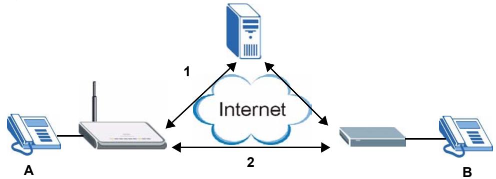
Figure 184 SIP ALG Example
18.5.3 SIP Signaling Session Timeout
Most SIP clients have an "expire" mechanism indicating the lifetime of signaling sessions. The SIP user agent sends registration packets to the SIP server periodically and keeps the session alive in the ZyXEL Device.
If the SIP client does not have this mechanism and makes no calls during the ZyXEL Device SIP timeout default (60 minutes), the ZyXEL Device SIP ALG drops any incoming calls after the timeout period.
18.5.4 SIP Audio Session Timeout
If no voice packets go through the SIP ALG before the timeout period (default 5 minutes) expires, the SIP ALG does not drop the call but blocks all voice traffic and deletes the audio session. You cannot hear anything and you will need to make a new call to continue your conversation.
18.6 ALG Screen
Click ADVANCED > ALG to open the ALG screen. Use the ALG screen to turn individual ALGs off or on and set the SIP timeout.
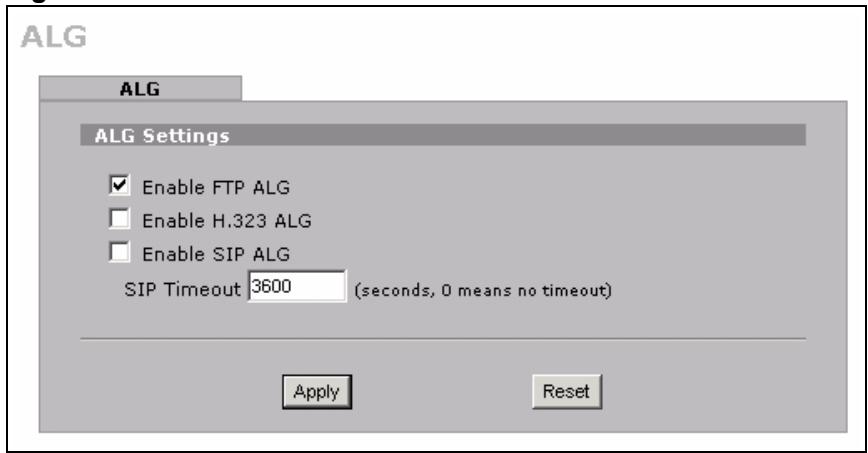
Figure 185 ADVANCED > ALG
The following table describes the labels in this screen.
Table 87 ADVANCED > ALG
| LABEL | DESCRIPTION |
| Enable FTP ALG | Select this check box to allow FTP sessions to pass through the ZyXEL Device. FTP (File Transfer Program) is a program that enables fast transfer of files, including large files that may not be possible by e-mail. |
| Enable H.323 ALG | Select this check box to allow H.323 sessions to pass through the ZyXEL Device. H.323 is a protocol used for audio communications over networks. |
| Enable SIP ALG | Select this check box to allow SIP sessions to pass through the ZyXEL Device. SIP is a signaling protocol used in VoIP (Voice over IP), the sending of voice signals over Internet Protocol. |
| SIP Timeout | Most SIP clients have an “expire” mechanism indicating the lifetime of signaling sessions. The SIP user agent sends registration packets to the SIP server periodically and keeps the session alive in the ZyXEL Device. If the SIP client does not have this mechanism and makes no calls during the ZyXEL Device SIP timeout (default 60 minutes), the ZyXEL Device SIP ALG drops any incoming calls after the timeout period. Enter the SIP signaling session timeout value. |
| Apply | Click Apply to save your changes. |
| Reset | Click Reset to begin configuring this screen afresh. |
PART VI
Logs and
Maintenance
Logs Screens (301)
Maintenance (325)
This chapter contains information about configuring general log settings and viewing the ZyXEL Device's logs. Refer to Section 19.5 on page 312 for example log message explanations.
19.1 Configuring View Log
The web configurator allows you to look at all of the ZyXEL Device's logs in one location.
Click LOGS to open the View Log screen. Use the View Log screen to see the logs for the categories that you selected in the Log Settings screen (see Section 19.3 on page 304). Options include logs about system maintenance, system errors, access control, allowed or blocked web sites, blocked web features (such as ActiveX controls, java and cookies), attacks (such as DoS) and IPSec.
Log entries in red indicate system error logs. The log wraps around and deletes the old entries after it fills. Click a column heading to sort the entries. A triangle indicates ascending or descending sort order.
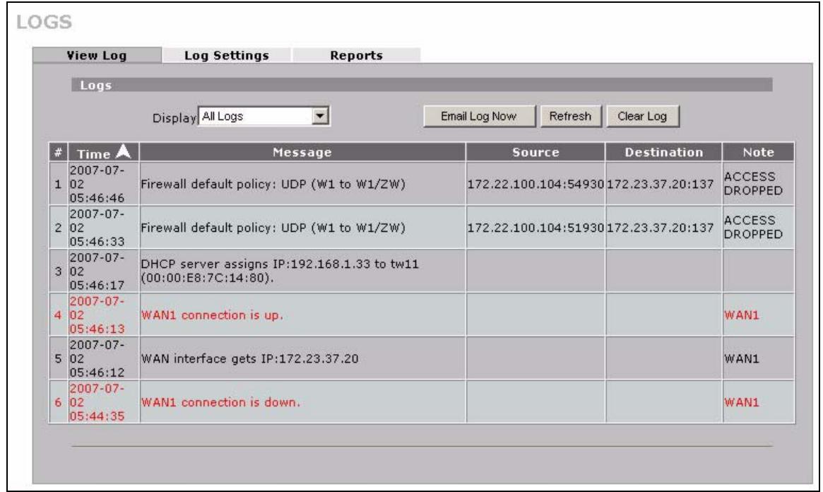
Figure 186 LOGS > View Log
The following table describes the labels in this screen.
Table 88 LOGS > View Log
| LABEL | DESCRIPTION |
| Display | The categories that you select in the Log Settings page (see Section 19.3 on page 304) display in the drop-down list box. Select a category of logs to view; select All Logs to view logs from all of the log categories that you selected in the Log Settings page. |
| # | This field displays the log number. |
| Time | This field displays the time the log was recorded. See Section 20.4 on page 327 to configure the ZyXEL Device's time and date. |
| Message | This field states the reason for the log. |
| Source | This field lists the source IP address and the port number of the incoming packet. |
| Destination | This field lists the destination IP address and the port number of the incoming packet. |
| Note | This field displays additional information about the log entry. |
| Email Log Now | Click Email Log Now to send the log screen to the e-mail address specified in the Log Settings page (make sure that you have first filled in the E-mail Log Settings fields in Log Settings, see Section 19.3 on page 304). |
| Refresh | Click Refresh to renew the log screen. |
| Clear Log | Click Clear Log to delete all the logs. |
19.2 Log Description Example
The following is an example of how a log displays in the command line interpreter and a description of the sample log. Refer to the Section 19.5 on page 312 for more log message descriptions and the appendix for details on using the command line interpreter to display logs.
time source destination notes message 5|06/08/2004 05:58:20 |172.21.4.187:137 ACCESS BLOCK Firewall default policy: UDP (W to W/ZW)
Table 89 Log Description Example
| LABEL | DESCRIPTION |
| # | This is log number five. |
| time | The log was generated on June 8, 2004 at 5:58 and 20 seconds AM. |
| source | The log was generated due to a NetBIOS packet sent from IP address 172.21.4.187 port 137. |
| destination | The NetBIOS packet was sent to the 172.21.255.255 subnet port 137. This was a NetBIOS UDP broadcast packet meant to discover devices on the network. |
Table 89 Log Description Example
| LABEL | DESCRIPTION |
| notes | The ZyXEL Device blocked the packet. |
| message | The ZyXEL Device blocked the packet in accordance with the firewall's default policy of blocking sessions that are initiated from the WAN. “UDP” means that this was a User Datagram Protocol packet. “W to W/ZW” indicates that the packet was traveling from the WAN to the WAN or the ZyXEL Device. |
19.2.1 About the Certificate Not Trusted Log
myZyXEL.com and the update server use certificates signed by VeriSign to identify themselves. If the ZyXEL Device does not have a CA certificate signed by VeriSign as a trusted CA, the ZyXEL Device will not trust the certificate from myZyXEL.com and the update server. The ZyXEL Device will generate a log like "Due to error code(11), cert not trusted: SSL/TLS peer certif..." for every time it attempt to establish a (HTTPS) connection with myZyXEL.com and the update server. The V4.00 default configuration file includes a trusted CA certificate signed by VeriSign. If you upgraded to ZyNOS V4.00 firmware without uploading the V4.00 default configuration file, you can download a CA certificate signed by VeriSign from myZyXEL.com and import it into the ZyXEL Device as a trusted CA. This will stop the ZyXEL Device from generating this log every time it attempts to connect with myzyxel.com and the update server.
Follow the steps below to download the certificate from myZyXEL.com.
1 Go to http://www.myZyXEL.com and log in with your account.
2 Click Download Center and then Certificate Download.
Figure 187 myZyXEL.com: Download Center
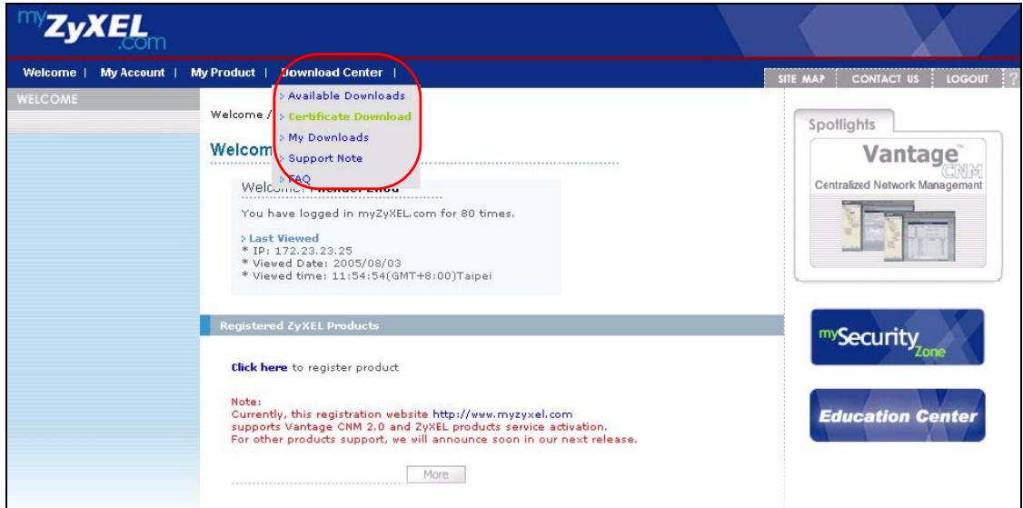
3 Click the link in the Certificate Download screen.
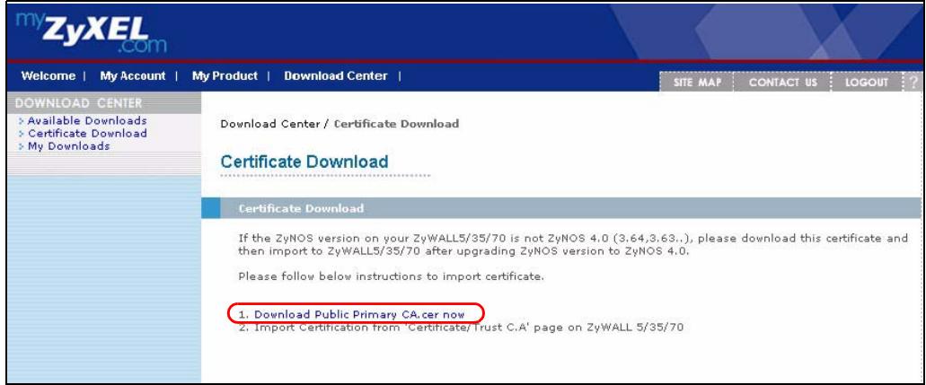
Figure 188 myZyXEL.com: Certificate Download
19.3 Configuring Log Settings
To change your ZyXEL Device's log settings, click LOGS > Log Settings. The screen appears as shown.
Use the Log Settings screen to configure to where the ZyXEL Device is to send logs; the schedule for when the ZyXEL Device is to send the logs and which logs and/or immediate alerts the ZyXEL Device is to send.
An alert is a type of log that warrants more serious attention. They include system errors, attacks (access control) and attempted access to blocked web sites or web sites with restricted web features such as cookies, active X and so on. Some categories such as System Errors consist of both logs and alerts. You may differentiate them by their color in the View Log screen. Alerts display in red and logs display in black.

Alerts are e-mailed as soon as they happen. Logs may be e-mailed as soon as the log is full (see Log Schedule). Selecting many alert and/or log categories (especially Access Control) may result in many e-mails being sent.
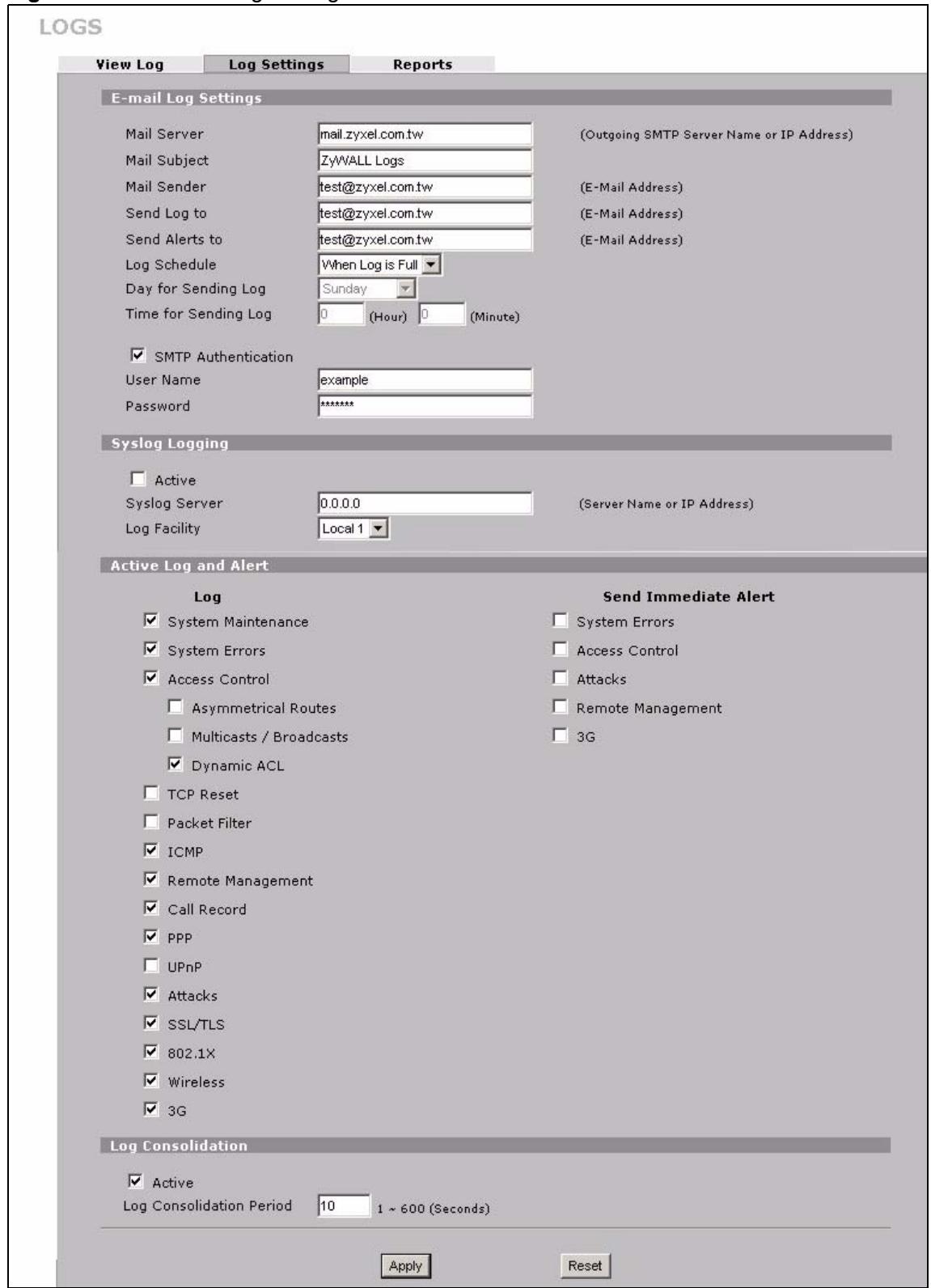
Figure 189 LOGS > Log Settings
The following table describes the labels in this screen.
Table 90 LOGS > Log Settings
| LABEL | DESCRIPTION |
| E-mail Log Settings | |
| Mail Server | Enter the server name or the IP address of the mail server for the e-mail addresses specified below. If this field is left blank, logs and alert messages will not be sent via e-mail. |
| Mail Subject | Type a title that you want to be in the subject line of the log e-mail message that the ZyxEL Device sends. |
| Mail Sender | Enter the e-mail address that you want to be in the from/sender line of the log e-mail message that the ZyxEL Device sends. If you activate SMTP authentication, the e-mail address must be able to be authenticated by the mail server as well. |
| Send Log To | Logs are sent to the e-mail address specified in this field. If this field is left blank, logs will not be sent via e-mail. |
| Send Alerts To | Alerts are sent to the e-mail address specified in this field. If this field is left blank, alerts will not be sent via e-mail. |
| Log Schedule | This drop-down menu is used to configure the frequency of log messages being sent as E-mail: Daily Weekly Hourly When Log is Full None. If you select Weekly or Daily, specify a time of day when the E-mail should be sent. If you select Weekly, then also specify which day of the week the E-mail should be sent. If you select When Log is Full, an alert is sent when the log fills up. If you select None, no log messages are sent. |
| Day for Sending Log | Use the drop down list box to select which day of the week to send the logs. |
| Time for Sending Log | Enter the time of the day in 24-hour format (for example 23:00 equals 11:00 pm) to send the logs. |
| SMTP Authentication | SMTP (Simple Mail Transfer Protocol) is the message-exchange standard for the Internet. SMTP enables you to move messages from one e-mail server to another. Select the check box to activate SMTP authentication. If mail server authentication is needed but this feature is disabled, you will not receive the e-mail logs. |
| User Name | Enter the user name (up to 31 characters) (usually the user name of a mail account). |
| Password | Enter the password associated with the user name above. |
| Syslog Logging | Syslog allows you to send system logs to a server. Syslog logging sends a log to an external syslog server. |
| Active | Click Active to enable syslog logging. |
| Syslog Server | Enter the server name or IP address of the syslog server that will log the selected categories of logs. |
| Log Facility | Select a location from the drop down list box. The log facility allows you to log the messages to different files in the syslog server. Refer to the documentation of your syslog program for more details. |
| Active Log and Alert | |
| Log | Select the categories of logs that you want to record. Logs include alerts. |
| Send Immediate Alert | Select the categories of alerts for which you want the ZyXEL Device to instantly e-mail alerts to the e-mail address specified in the Send Alerts To field. |
| Log Consolidation | |
| Active | Some logs (such as the Attacks logs) may be so numerous that it becomes easy to ignore other important log messages. Select this check box to merge logs with identical messages into one log. You can use the sys log consolidate msglist command to see what log messages will be consolidated. |
| Log Consolidation Period | Specify the time interval during which the ZyXEL Device merges logs with identical messages into one log. |
| Apply | Click Apply to save your changes. |
| Reset | Click Reset to begin configuring this screen afresh. |
19.4 Configuring Reports
The Reports screen displays which computers on the LAN or DMZ send and receive the most traffic, what kinds of traffic are used the most and which web sites are visited the most often. The ZyXEL Device can record and display the following network usage details:
- Web sites visited the most often
Number of times the most visited web sites were visited - The most-used protocols or service ports
- The amount of traffic for the most used protocols or service ports
- The LAN or DMZ IP addresses to and/or from which the most traffic has been sent
- How much traffic has been sent to and from the LAN or DMZ IP addresses to and/or from which the most traffic has been sent

The web site hit count may not be 100% accurate because sometimes when an individual web page loads, it may contain references to other web sites that also get counted as hits.
The ZyXEL Device records web site hits by counting the HTTP GET packets. Many web sites include HTTP GET references to other web sites and the ZyXEL Device may count these as hits, thus the web hit count is not (yet) 100% accurate.
Click LOGS > Reports to display the following screen.
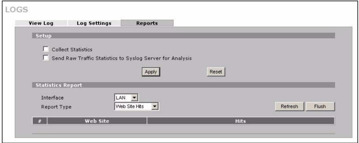
Figure 190 LOGS > Reports

Enabling the ZyXEL Device's reporting function decreases the overall throughput by about 1 Mbps.
The following table describes the labels in this screen.
Table 91 LOGS > Reports
| LABEL | DESCRIPTION |
| Collect Statistics | Select the check box and click Apply to have the ZyXEL Device record report data. |
| Send Raw Traffic Statistics to Syslog Server for Analysis | Select the check box and click Apply to have the ZyXEL Device send unprocessed traffic statistics to a syslog server for analysis. You must have the syslog server already configured in the Log Settings screen. |
| Apply | Click Apply to save your changes to the ZyXEL Device. |
| Reset | Click Reset to begin configuring this screen afresh. |
| Interface | Select on which interface (LAN or DMZ) the logs will be collected. The logs on the DMZ or LAN IP alias 1 and 2 are also recorded. |
| Report Type | Use the drop-down list box to select the type of reports to display. Web Site Hits displays the web sites that have been visited the most often from the LAN and how many times they have been visited. Protocol/Port displays the protocols or service ports that have been used the most and the amount of traffic for the most used protocols or service ports. Host IP Address displays the LAN or DMZ IP addresses to and /or from which the most traffic has been sent and how much traffic has been sent to and from those IP addresses. |
| Refresh | Click Refresh to update the report display. The report also refreshes automatically when you close and reopen the screen. |
| Flush | Click Flush to discard the old report data and update the report display. |

All of the recorded reports data is erased when you turn off the ZyXEL Device.
19.4.1 Viewing Web Site Hits
In the Reports screen, select Web Site Hits from the Report Type drop-down list box to have the ZyXEL Device record and display which web sites have been visited the most often and how many times they have been visited.
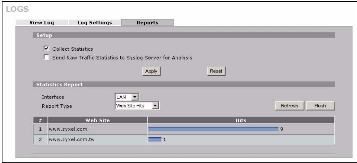
Figure 191 LOGS > Reports: Web Site Hits Example
The following table describes the label in this screen.
Table 92 LOGS > Reports: Web Site Hits Report
| LABEL | DESCRIPTION |
| Web Site | This column lists the domain names of the web sites visited most often from computers on the LAN or DMZ. The names are ranked by the number of visits to each web site and listed in descending order with the most visited web site listed first. The ZyXEL Device counts each page viewed in a web site as another hit on the web site. |
| Hits | This column lists how many times each web site has been visited. The count starts over at 0 if a web site passes the hit count limit (see Table 95 on page 312). |
19.4.2 Viewing Host IP Address
In the Reports screen, select Host IP Address from the Report Type drop-down list box to have the ZyXEL Device record and display the LAN or DMZ IP addresses that the most traffic has been sent to and/or from and how much traffic has been sent to and/or from those IP addresses.

Computers take turns using dynamically assigned LAN or DMZ IP addresses. The ZyXEL Device continues recording the bytes sent to or from a LAN or DMZ IP address when it is assigned to a different computer.
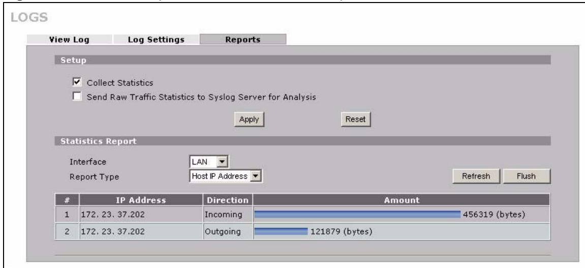
Figure 192 LOGS > Reports: Host IP Address Example
The following table describes the labels in this screen.
Table 93 LOGS > Reports: Host IP Address
| LABEL | DESCRIPTION |
| IP Address | This column lists the LAN or DMZ IP addresses to and/or from which the most traffic has been sent. The LAN or DMZ IP addresses are listed in descending order with the LAN or DMZ IP address to and/or from which the most traffic was sent listed first. |
| Direction | This field displays Incoming to denote traffic that is coming in from the WAN to the LAN or DMZ. This field displays Outgoing to denote traffic that is going out from the LAN or DMZ to the WAN. |
| Amount | This column displays how much traffic has gone to and from the listed LAN or DMZ IP addresses. The measurement unit shown (bytes, Kbytes, Mbytes or Gbytes) varies with the amount of traffic sent to and from the LAN or DMZ IP address. The count starts over at 0 if the total traffic sent to and from a LAN or DMZ IP passes the bytes count limit (see Table 95 on page 312). |
19.4.3 Viewing Protocol/Port
In the Reports screen, select Protocol/Port from the Report Type drop-down list box to have the ZyXEL Device record and display which protocols or service ports have been used the most and the amount of traffic for the most used protocols or service ports.
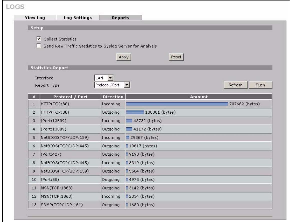
Figure 193 LOGS > Reports: Protocol/Port Example
The following table describes the labels in this screen.
Table 94 LOGS > Reports: Protocol/ Port
| LABEL | DESCRIPTION |
| Protocol/Port | This column lists the protocols or service ports for which the most traffic has gone through the ZyXEL Device. The protocols or service ports are listed in descending order with the most used protocol or service port listed first. |
| Direction | This field displays Incoming to denote traffic that is coming in from the WAN to the LAN or DMZ. This field displays Outgoing to denote traffic that is going out from the LAN or DMZ to the WAN. |
| Amount | This column lists how much traffic has been sent and/or received for each protocol or service port. The measurement unit shown (bytes, Kbytes, Mbytes or Gbytes) varies with the amount of traffic for the particular protocol or service port. The count starts over at 0 if a protocol or port passes the bytes count limit (see Table 95 on page 312). |
19.4.4 System Reports Specifications
The following table lists detailed specifications on the reports feature.
Table 95 Report Specifications
| LABEL | DESCRIPTION |
| Number of web sites/protocols or ports/IP addresses listed: | 20 |
| Hit count limit: | Up to 232 hits can be counted per web site. The count starts over at 0 if it passes four billion. |
| Bytes count limit: | Up to 264 bytes can be counted per protocol/port or LAN IP address. The count starts over at 0 if it passes 264 bytes. |
19.5 Log Descriptions
This section provides descriptions of example log messages.
Table 96 System Maintenance Logs
| LOGMESSAGE | DESCRIPTION |
| Time calibration is successful | The router has adjusted its time based on information from the time server. |
| Time calibration failed | The router failed to get information from the time server. |
| WAN interface gets IP:%s | A WAN interface got a new IP address from the DHCP, PPPoE, PPTP or dial-up server. |
| DHCP client IP expired | A DHCP client's IP address has expired. |
| DHCP server assigns %s | The DHCP server assigned an IP address to a client. |
| Successful WEB login | Someone has logged on to the router's web configurator interface. |
| WEB login failed | Someone has failed to log on to the router's web configurator interface. |
| Successful TELNET login | Someone has logged on to the router via telnet. |
| TELNET login failed | Someone has failed to log on to the router via telnet. |
| Successful FTP login | Someone has logged on to the router via FTP. |
| FTP login failed | Someone has failed to log on to the router via FTP. |
| NAT Session Table is Full! | The maximum number of NAT session table entries has been exceeded and the table is full. |
| Starting Connectivity Monitor | Starting Connectivity Monitor. |
| Time initialized by Daytime Server | The router got the time and date from the Daytime server. |
| Time initialized by Time server | The router got the time and date from the time server. |
| Time initialized by NTP server | The router got the time and date from the NTP server. |
| Connect to Daytime server fail | The router was not able to connect to the Daytime server. |
| Connect to Time server fail | The router was not able to connect to the Time server. |
| Connect to NTP server fail | The router was not able to connect to the NTP server. |
| Too large ICMP packet has been dropped | The router dropped an ICMP packet that was too large. |
| Configuration Change: PC = 0x%x, Task ID = 0x%x | The router is saving configuration changes. |
| Successful SSH login | Someone has logged on to the router's SSH server. |
| SSH login failed | Someone has failed to log on to the router's SSH server. |
| Successful HTTPS login | Someone has logged on to the router's web configurator interface using HTTPS protocol. |
| HTTPS login failed | Someone has failed to log on to the router's web configurator interface using HTTPS protocol. |
| DNS server %s was not responding to last 32 consecutive queries... | The specified DNS server did not respond to the last 32 consecutive queries. |
| DDNS update IP:%s (host %d) successfully | The device updated the IP address of the specified DDNS host name. |
| SMTP successfully | The device sent an e-mail. |
Table 97 System Error Logs
| LOGMESSAGE | DESCRIPTION |
| %sexceeds the max. number of session per host! | This attempt to create a NAT session exceeds the maximum number of NAT session table entries allowed to be created per host. |
| setNetBIOSFilter:%X | The router failed to allocate memory for the NetBIOS filter settings. |
| readNetBIOSFilter:%X | The router failed to allocate memory for the NetBIOS filter settings. |
| WAN connection is down. | A WAN connection is down. You cannot access the network through this interface. |
| DHCP Server cannot assign the static IP %S (out of range). | The LAN subnet, LAN alias 1, or LAN alias 2 was changed and the specified static DHCP IP addresses are no longer valid. |
| The DHCP static IP %s is conflict. | The static DHCP IP address conflicts with another host. |
| SMTP fail (%s) | The device failed to send an e-mail (error message included). |
| SMTP authentication fail (%s) | The device failed to authenticate with the SMTP server (error message included). |
Table 98 Access Control Logs
| LOGMESSAGE | DESCRIPTION |
| Firewall default policy: [ TCP | UDP | IGMP | ESP | GRE | OSPF ] <Packet Direction> | Attempted TCP/UDP/IGMP/ESP/GRE/OSPF access matched the default policy and was blocked or forwarded according to the default policy's setting. |
| Firewall rule [NOT] match: [ TCP | UDP | IGMP | ESP | GRE | OSPF ] <Packet Direction>, <rule:%d> | Attempted TCP/UDP/IGMP/ESP/GRE/OSPF access matched (or did not match) a configured firewall rule (denoted by its number) and was blocked or forwarded according to the rule. |
| Triangle route packet forwarded: [ TCP | UDP | IGMP | ESP | GRE | OSPF ] | The firewall allowed a triangle route session to pass through. |
| Packet without a NAT table entry blocked: [ TCP | UDP | IGMP | ESP | GRE | OSPF ] | The router blocked a packet that didn't have a corresponding NAT table entry. |
| Router sent blocked web site message: TCP | The router sent a message to notify a user that the router blocked access to a web site that the user requested. |
| Exceed maximum sessions per host (%d). | The device blocked a session because the host's connections exceeded the maximum sessions per host. |
| Firewall allowed a packet that matched a NAT session: [ TCP | UDP ] | A packet from the WAN (TCP or UDP) matched a cone NAT session and the device forwarded it to the LAN. |
Table 99 TCP Reset Logs
| LOGMESSAGE | DESCRIPTION |
| Under SYN flood attack, sent TCP RST | The router sent a TCP reset packet when a host was under a SYN flood attack (the TCP incomplete count is per destination host.) |
| Exceed TCP MAX incomplete, sent TCP RST | The router sent a TCP reset packet when the number of TCP incomplete connections exceeded the user configured threshold. (the TCP incomplete count is per destination host.) Note: Refer to TCP Maximum Incomplete in the Firewall Attack Alerts screen. |
| Peer TCP state out of order, sent TCP RST | The router sent a TCP reset packet when a TCP connection state was out of order.Note: The firewall refers to RFC793 Figure 6 to check the TCP state. |
| Firewall session time out, sent TCP RST | The router sent a TCP reset packet when a dynamic firewall session timed out.The default timeout values are as follows:ICMP idle timeout: 3 minutesUDP idle timeout: 3 minutesTCP connection (three way handshaking) timeout: 270 secondsTCP FIN-wait timeout: 2 MSL (Maximum Segment Lifetime set in the TCP header).TCP idle (established) timeout (s): 150 minutesTCP reset timeout: 10 seconds |
| Exceed MAX incomplete, sent TCP RST | The router sent a TCP reset packet when the number of incomplete connections (TCP and UDP) exceeded the user-configured threshold. (Incomplete count is for all TCP and UDP connections through the firewall.)Note: When the number of incomplete connections (TCP + UDP) > “Maximum Incomplete High”, the router sends TCP RST packets for TCP connections and destroys TOS (firewall dynamic sessions) until incomplete connections < “Maximum Incomplete Low”. |
| Access block, sent TCP RST | The router sends a TCP RST packet and generates this log if you turn on the firewall TCP reset mechanism (via CI command: "sys firewall tcprst"). |
Table 100 Packet Filter Logs
| LOGMESSAGE | DESCRIPTION |
| [TCP | UDP | ICMP | IGMP | Generic ] packet filter matched (set:%d, rule:%d) | Attempted access matched a configured filter rule (denoted by its set and rule number) and was blocked or forwarded according to the rule. |
For type and code details, see Table 110 on page 321.
Table 101 ICMP Logs
| LOGMESSAGE | DESCRIPTION |
| Firewall default policy: ICMP <Packet Direction>, <type:%d>, <code:%d> | ICMP access matched the default policy and was blocked or forwarded according to the user's setting. |
| Firewall rule [NOT] match: ICMP <Packet Direction>, <rule:%d>, <type:%d>, <code:%d> | ICMP access matched (or didn't match) a firewall rule (denoted by its number) and was blocked or forwarded according to the rule. |
| Triangle route packet forwarded: ICMP | The firewall allowed a triangle route session to pass through. |
| Packet without a NAT table entry blocked: ICMP | The router blocked a packet that didn't have a corresponding NAT table entry. |
| Unsupported/out-of-order ICMP: ICMP | The firewall does not support this kind of ICMP packets or the ICMP packets are out of order. |
| Router reply ICMP packet: ICMP | The router sent an ICMP reply packet to the sender. |
Table 102 Remote Management Logs
| LOGMESSAGE | DESCRIPTION |
| Remote Management: FTP denied | Attempted use of FTP service was blocked according to remote management settings. |
| Remote Management: TELNET denied | Attempted use of TELNET service was blocked according to remote management settings. |
| Remote Management: HTTP or UPnP denied | Attempted use of HTTP or UPnP service was blocked according to remote management settings. |
| Remote Management: WWW denied | Attempted use of WWW service was blocked according to remote management settings. |
Table 102 Remote Management Logs
| LOGMESSAGE | DESCRIPTION |
| Remote Management: HTTPS denied | Attempted use of HTTPS service was blocked according to remote management settings. |
| Remote Management: SSH denied | Attempted use of SSH service was blocked according to remote management settings. |
| Remote Management: ICMP Ping response denied | Attempted use of ICMP service was blocked according to remote management settings. |
| Remote Management: SNMP denied | Attempted use of SNMP service was blocked according to remote management settings. |
| Remote Management: DNS denied | Attempted use of DNS service was blocked according to remote management settings. |
Table 103 CDR Logs
| LOGMESSAGE | DESCRIPTION |
| board %d line %d channel %d, call %d, %s C01 Outgoing Call dev=%x ch=%x %s | The router received the setup requirements for a call. "call" is the reference (count) number of the call. "dev" is the device type (3 is for dial-up, 6 is for PPPoE, 10 is for PPTP). "channel" or "ch" is the call channel ID. For example, "board 0 line 0 channel 0, call 3, C01 Outgoing Call dev=6 ch=0 "Means the router has dialed to the PPPoE server 3 times. |
| board %d line %d channel %d, call %d, %s C02 OutCall Connected %d %s | The PPPoE, PPTP or dial-up call is connected. |
| board %d line %d channel %d, call %d, %s C02 Call Terminated | The PPPoE, PPTP or dial-up call was disconnected. |
Table 104 PPP Logs
| LOGMESSAGE | DESCRIPTION |
| ppp:LCP Starting | The PPP connection's Link Control Protocol stage has started. |
| ppp:LCP Opening | The PPP connection's Link Control Protocol stage is opening. |
| ppp:CHAP Opening | The PPP connection's Challenge Handshake Authentication Protocol stage is opening. |
| ppp:IPCP Starting | The PPP connection's Internet Protocol Control Protocol stage is starting. |
| ppp:IPCP Opening | The PPP connection's Internet Protocol Control Protocol stage is opening. |
| ppp:LCP Closing | The PPP connection's Link Control Protocol stage is closing. |
| ppp:IPCP Closing | The PPP connection's Internet Protocol Control Protocol stage is closing. |
Table 105 UPnP Logs
| LOGMESSAGE | DESCRIPTION |
| UPnP pass through Firewall | UPnP packets can pass through the firewall. |
For type and code details, see Table 110 on page 321.
Table 106 Attack Logs
| LOGMESSAGE | DESCRIPTION |
| attack [ TCP | UDP | IGMP | ESP | GRE | OSPF ] | The firewall detected a TCP/UDP/IGMP/ESP/GRE/OSPF attack. |
| attack ICMP (type:%d, code:%d) | The firewall detected an ICMP attack. |
| land [ TCP | UDP | IGMP | ESP | GRE | OSPF ] | Thefirewall detected a TCP/UDP/IGMP/ESP/GRE/OSPF land attack. |
| land ICMP (type:%d, code:%d) | Thefirewall detected an ICMP land attack. |
| ip spoofing - WAN [ TCP | UDP | IGMP | ESP | GRE | OSPF ] | Thefirewall detected an IP spoofing attack on the WAN port. |
| ip spoofing - WAN ICMP (type:%d, code:%d) | Thefirewall detected an ICMP IP spoofing attack on the WAN port. |
| icmp echo : ICMP (type:%d, code:%d) | Thefirewall detected an ICMP echo attack. |
| syn flood TCP | Thefirewall detected a TCP syn flood attack. |
| ports scan TCP | Thefirewall detected a TCP port scan attack. |
| teardrop TCP | Thefirewall detected a TCP teardrop attack. |
| teardrop UDP | Thefirewall detected an UDP teardrop attack. |
| teardrop ICMP (type:%d, code:%d) | Thefirewall detected an ICMP teardrop attack. |
| illegal command TCP | Thefirewall detected a TCP illegal command attack. |
| NetBIOS TCP | Thefirewall detected a TCP NetBIOS attack. |
| ip spoofing - no routing entry [ TCP | UDP | IGMP | ESP | GRE | OSPF ] | Thefirewall classified a packet with no source routing entry as an IP spoofing attack. |
| ip spoofing - no routing entry ICMP (type:%d, code:%d) | Thefirewall classified an ICMP packet with no source routing entry as an IP spoofing attack. |
| vulnerability ICMP (type:%d, code:%d) | Thefirewall detected an ICMP vulnerability attack. |
| traceroute ICMP (type:%d, code:%d) | Thefirewall detected an ICMP traceroute attack. |
| ports scan UDP | Thefirewall detected a UDP port scan attack. |
| Firewall sent TCP packet in response to DoS attack TCP | Thefirewall sent TCP packet in response to a DoS attack |
| ICMP Source Quench ICMP | Thefirewall detected an ICMP Source Quench attack. |
| ICMP Time Exceed ICMP | Thefirewall detected an ICMP Time Exceed attack. |
| ICMP Destination Unreachable ICMP | Thefirewall detected an ICMP Destination Unreachable attack. |
| ping of death. ICMP | Thefirewall detected an ICMP ping of death attack. |
| smurf ICMP | Thefirewall detected an ICMP smurf attack. |
| IP address in FTP port command is different from the client IP address. It maybe a bounce attack. | The IP address in an FTP port command is different from the client IP address. It may be a bounce attack. |
| Fragment packet size is smaller than the MTU size of output interface. | The fragment packet size is smaller than the MTU size of output interface. |
Table 107 3G Logs
| LOGMESSAGE | DESCRIPTION |
| SIM/3G interface mismatch:%s. | The ID number of the currently selected interface or SIM card is different from the previous one configured for budget control. |
| Preconfigured SIM card/3G interface doesn't match inserted card. Might need to reconfigure budget control settings. | The 3G interface is different from the previous one configured for budget control. You may need to reconfigure budget control settings specific to the current user account. |
| Budget counters are reset, budget control is resumed. | The ZyXEL Device restarted budget calculation from 0 after resetting the existing statistics. |
| Budget control is resumed. | The ZyXEL Device kept the existing budget control statistics and continue a counting. |
| Budget control is disabled. | Budget control is deactivated for the user account of the 3G interface on the ZyXEL Device. |
| Skip 3G SIM authentication because 3G configuration is not set. | The ZyXEL Device skipped SIM card authentication because the PIN code is not specified or SIM card authentication is disabled. |
| 3G SIM authentication failed because of no response from SIM card. | SIM card authentication failed because the ZyXEL Device received a SIM busy message three times when querying for the card status. |
| 3G SIM card PIN code is incorrect. | The specified PIN code does not match the 3G interface. |
| SIM card not inserted or damaged. | There is no SIM card inserted or the SIM card is damaged. |
| 3G connection has been dropped - %s. | The 3G connection has been dropped due to the specific reason, such as idle timeout, manual disconnection, failure to get an IP address, switching to WAN 1, ping check failure, connection reset, and so on. |
| Warning: (%IMSI% or %ESN%) Over time budget! (budget = %CONFIGURED_BUDGET% hours, used = %USEDVolumes(2 decimals) hours). | This shows that the preconfigured time budget was exceeded. This also displays the ID number of the selected 3G interface or SIM card and the 3G connection's usage time in hours. |
| Warning: (%IMSI% or %ESN%) Over %THRESHOLD% of time budget (%REMAIN_BUDGET%(2 decimals) hours remain in %CONFIGURED_BUDGET% hours budget). | This shows that the specified percentage of the time budget was exceeded. This also displays the ID number of the selected 3G interface or SIM card and the amount of time (in hours) the 3G connection can still be used. |
| Warning: (%ESN% or %IMSI%) Over data budget! (budget =%CONFIGURED_BUDGET%(2 decimals Mbytes, used = %USEDVolumes%(2 decimals) ). | This shows that the preconfigured data limit was exceeded. The ID number of the selected 3G interface or SIM card is displayed. The amount of data (in Mbytes) sent and/or received (depending on your configuration) through the 3G connection is also displayed. |
| Warning: (%ESN% or %IMSI%) Over %THRESHOLD%% of data budget (%REMAIN_BUDGET%(2 decimals) Mbytes remain in %CONFIGURED_BUDGET% Mbytes budget). | This shows that the specified percentage of data limit was exceeded. This also displays the ID number of the selected 3G interface or SIM card and how much data (in Mbytes) can still be transmitted through the 3G connection. |
Table 108 PKI Logs
| LOGMESSAGE | DESCRIPTION |
| Enrollment successful | The SCEP online certificate enrollment was successful. The Destination field records the certification authority server IP address and port. |
| Enrollment failed | The SCEP online certificate enrollment failed. The Destination field records the certification authority server's IP address and port. |
| Failed to resolve <SCEP CA server url> | The SCEP online certificate enrollment failed because the certification authority server's address cannot be resolved. |
| Enrollment successful | The CMP online certificate enrollment was successful. The Destination field records the certification authority server's IP address and port. |
| Enrollment failed | The CMP online certificate enrollment failed. The Destination field records the certification authority server's IP address and port. |
| Failed to resolve <CMP CA server url> | The CMP online certificate enrollment failed because the certification authority server's IP address cannot be resolved. |
| Rcvd ca cert: <subject name> | The router received a certification authority certificate, with subject name as recorded, from the LDAP server whose IP address and port are recorded in the Source field. |
| Rcvd user cert: <subject name> | The router received a user certificate, with subject name as recorded, from the LDAP server whose IP address and port are recorded in the Source field. |
| Rcvd CRL <size>: <issuer name> | The router received a CRL (Certificate Revocation List), with size and issuer name as recorded, from the LDAP server whose IP address and port are recorded in the Source field. |
| Rcvd ARL <size>: <issuer name> | The router received an ARL (Authority Revocation List), with size and issuer name as recorded, from the LDAP server whose address and port are recorded in the Source field. |
| Failed to decode the received ca cert | The router received a corrupted certification authority certificate from the LDAP server whose address and port are recorded in the Source field. |
| Failed to decode the received user cert | The router received a corrupted user certificate from the LDAP server whose address and port are recorded in the Source field. |
| Failed to decode the received CRL | The router received a corrupted CRL (Certificate Revocation List) from the LDAP server whose address and port are recorded in the Source field. |
| Failed to decode the received ARL | The router received a corrupted ARL (Authority Revocation List) from the LDAP server whose address and port are recorded in the Source field. |
| Rcvd data <size> too large! Max size allowed: <max size> | The router received directory data that was too large (the size is listed) from the LDAP server whose address and port are recorded in the Source field. The maximum size of directory data that the router allows is also recorded. |
| Cert trusted: <subject name> | The router has verified the path of the certificate with the listed subject name. |
| Due to <reason codes>, cert not trusted:<subject name> | Due to the reasons listed, the certificate with the listed subject name has not passed the path verification. The recorded reason codes are only approximate reasons for not trusting the certificate. Please see Table 113 on page 320 for the corresponding descriptions of the codes. |
| CODE | DESCRIPTION |
| 1 | Algorithm mismatch between the certificate and the search constraints. |
| 2 | Key usage mismatch between the certificate and the search constraints. |
| 3 | Certificate was not valid in the time interval. |
| 4 | (Not used) |
| 5 | Certificate is not valid. |
| 6 | Certificate signature was not verified correctly. |
| 7 | Certificate was revoked by a CRL. |
| 8 | Certificate was not added to the cache. |
| 9 | Certificate decoding failed. |
| 10 | Certificate was not found (anywhere). |
| 11 | Certificate chain looped (did not find trusted root). |
| 12 | Certificate contains critical extension that was not handled. |
| 13 | Certificate issuer was not valid (CA specific information missing). |
| 14 | (Not used) |
| 15 | CRL is too old. |
| 16 | CRL is not valid. |
| 17 | CRL signature was not verified correctly. |
| 18 | CRL was not found (anywhere). |
| 19 | CRL was not added to the cache. |
| 20 | CRL decoding failed. |
| 21 | CRL is not currently valid, but in the future. |
| 22 | CRL contains duplicate serial numbers. |
| 23 | Time interval is not continuous. |
| 24 | Time information not available. |
| 25 | Database method failed due to timeout. |
| 26 | Database method failed. |
| 27 | Path was not verified. |
| 28 | Maximum path length reached. |
Table 109 ACL Setting Notes
| PACKET DIRECTION | DIRECTION | DESCRIPTION |
| (L to W) | LAN to WAN | ACL set for packets traveling from the LAN to the WAN. |
| (W to L) | WAN to LAN | ACL set for packets traveling from the WAN to the LAN. |
| (D to L) | DMZ to LAN | ACL set for packets traveling from the DMZ to the LAN. |
| (D to W) | DMZ to WAN | ACL set for packets traveling from the DMZ to the WAN. |
| (W to D) | WAN to DMZ | ACL set for packets traveling from the WAN to the DMZ. |
| (L to D) | LAN to DMZ | ACL set for packets traveling from the LAN to the DMZ. |
| (L to L/ZW) | LAN to LAN/ZyxEL Device | ACL set for packets traveling from the LAN to the LAN or the ZyxEL Device. |
| (W to W/ZW) | WAN to WAN/ZyxEL Device | ACL set for packets traveling from the WAN to the WAN or the ZyxEL Device. |
| (D to D/ZW) | DMZ to DMZ/ZyxEL Device | ACL set for packets traveling from the DMZ to the DM or the ZyxEL Device. |
Table 110 ICMP Notes
| TYPE | CODE | DESCRIPTION |
| 0 | Echo Reply | |
| 0 | Echo reply message | |
| 3 | Destination Unreachable | |
| 0 | Net unreachable | |
| 1 | Host unreachable | |
| 2 | Protocol unreachable | |
| 3 | Port unreachable | |
| 4 | A packet that needed fragmentation was dropped because it was set to Don't Fragment (DF) | |
| 5 | Source route failed | |
| 4 | Source Quench | |
| 0 | A gateway may discard internet datagrams if it does not have the buffer space needed to queue the datagrams for output to the next network on the route to the destination network. | |
| 5 | Redirect | |
| 0 | Redirect datagrams for the Network | |
| 1 | Redirect datagrams for the Host | |
| 2 | Redirect datagrams for the Type of Service and Network | |
| 3 | Redirect datagrams for the Type of Service and Host | |
| 8 | Echo | |
| 0 | Echo message | |
| 11 | Time Exceeded | |
| 0 | Time to live exceeded in transit | |
| 1 | Fragment reassembly time exceeded | |
| 12 | Parameter Problem | |
| 0 | Pointer indicates the error | |
| 13 | Timestamp | |
| 0 | Timestamp request message | |
| 14 | Timestamp Reply | |
| 0 | Timestamp reply message | |
| 15 | Information Request | |
| 0 | Information request message | |
| 16 | Information Reply | |
| 0 | Information reply message |
19.6 Syslog Logs
There are two types of syslog: event logs and traffic logs. The device generates an event log when a system event occurs, for example, when a user logs in or the device is under attack. The device generates a traffic log when a "session" is terminated. A traffic log summarizes the session's type, when it started and stopped the amount of traffic that was sent and received and so on. An external log analyzer can reconstruct and analyze the traffic flowing through the device after collecting the traffic logs.
Table 111 Syslog Logs
| LOGMESSAGE | DESCRIPTION |
| Event Log: <Facility*8 + Severity>Mon dd hr:mm:ss hostname src="<srcIP:srcPort>" dst="<dstIP:dstPort>" msg="<msg>" note="<note>" devID="<mac address>" cat="category" | This message is sent by the system ("RAS" displays as the system name if you haven't configured one) when the router generates a syslog. The facility is defined in the web MAIN MENU > LOGS > Log Settings page. The severity is the log's syslog class. The definition of messages and notes are defined in the other log tables. The "devID" is the MAC address of the router's LAN port. The "cat" is the same as the category in the router's logs. |
| Traffic Log: <Facility*8 + Severity>Mon dd hr:mm:ss hostname src="<srcIP:srcPort>" dst="<dstIP:dstPort>" msg="Traffic Log" note="Traffic Log" devID="<mac address>" cat="Traffic Log" duration=seconds sent=sentBytes rcvd=receiveBytes dir="<from:to>" protoID=IPProtocolID proto="serviceName" trans="IPSec/Normal" | This message is sent by the device when the connection (session) is closed. The facility is defined in the Log Settings screen. The severity is the traffic log type. The message and note always display "Traffic Log". The "proto" field lists the service name. The "dir" field lists the incoming and outgoing interfaces ("LAN:LAN", "LAN:WAN", "LAN:DMZ", "LAN:DEV" for example). |
| Event Log: <Facility*8 + Severity>Mon dd hr:mm:ss hostname src="<srcIP:srcPort>" dst="<dstIP:dstPort>" ob="<0|1>" ob MacOS="<mac address>" msg="<msg>" note="<note>" devID="<mac address>" cat="category" | This message is sent by the device ("RAS" displays as the system name if you haven't configured one) at the time when this syslog is generated. The facility is defined in the web MAIN MENU > LOGS > Log Settings page. The severity is the log's syslog class. The definition of messages and notes are defined in the other log tables. OB is the Out Break flag and the mac address of the Out Break PC. |
| Event Log: <Facility*8 + Severity>Mon dd hr:mm:ss hostname src="<srcIP:srcPort>" dst="<dstIP:dstPort>" ob="0|1" ob MacOS="<mac address>" msg="<msg>" note="<note>" devID="<mac address>" cat="Anti Virus" encode="< uu | b64>" | This message is sent by the device ("RAS" displays as the system name if you haven't configured one) at the time when this syslog is generated. The facility is defined in the web MAIN MENU > LOGS > Log Settings page. The severity is the log's syslog class. The "encode" message indicates the mail attachments encoding method. The definition of messages and notes are defined in the Anti-Virus log descriptions. |
| Event Log: <Facility*8 + Severity>Mon dd hr:mm:ss hostname src="<srcIP:srcPort>" dst="<dstIP:dstPort>" ob="<0|1>" ab MacOS="<mac address>" msg="<msg>" note="<note>" devID="<mac address>" cat="IDP" class="<idp class>" sid="<idp sid> act="<idp action>" count="1" | This message is sent by the device ("RAS" displays as the system name if you haven't configured one) at the time when this syslog is generated. The facility is defined in the web MAIN MENU > LOGS > Log Settings page. The severity is the log's syslog class. The definition of messages and notes are defined in the IDP log descriptions. |
| Event Log: <Facility*8 + Severity>Mon dd hr:mm:ss hostname src="<srcIP:srcPort>" dst="<dstIP:dstPort>" ob="<0|1>" ab MacOS="<mac address>" msg="<msg>" note="<note>" devID="<mac address>" cat="Anti Spam" 1stReIP="<IP>" | This message is sent by the device ("RAS" displays as the system name if you haven't configured one) at the time when this syslog is generated. The facility is defined in the web MAIN MENU > LOGS > Log Settings page. The severity is the log's syslog class. 1stReIP is the IP address of the first mail relay server. The definition of messages and notes are defined in the Anti-Span log descriptions. |
The following table shows RFC-2408 ISAKMP payload types that the log displays. Please refer to the RFC for detailed information on each type.
Table 112 RFC-2408 ISAKMP Payload Types
| LOG DISPLAY | PAYLOAD TYPE |
| SA | Security Association |
| PROP | Proposal |
| TRANS | Transform |
| KE | Key Exchange |
| ID | Identification |
| CER | Certificate |
| CER_REQ | Certificate Request |
| HASH | Hash |
| SIG | Signature |
| NONCE | Nonce |
| NOTFY | Notification |
| DEL | Delete |
| VID | Vendor ID |
Maintenance
This chapter displays information on the maintenance screens.
20.1 Maintenance Overview
The maintenance screens can help you view system information, upload new firmware, manage configuration and restart your ZyXEL Device.
20.2 General Setup and System Name
General Setup contains administrative and system-related information. System Name is for identification purposes. However, because some ISPs check this name you should enter your computer's "Computer Name".
- In Windows 95/98 click Start, Settings, Control Panel, Network. Click the Identification tab, note the entry for the Computer Name field and enter it as the System Name.
- In Windows 2000, click Start, Settings, Control Panel and then double-click System. Click the Network Identification tab and then the Properties button. Note the entry for the Computer name field and enter it as the System Name.
- In Windows XP, click Start, My Computer, View system information and then click the Computer Name tab. Note the entry in the Full computer name field and enter it as the ZyXEL Device System Name.
20.2.1 General Setup
Click MAINTENANCE to open the General screen. Use this screen to configure administrative and system-related information.
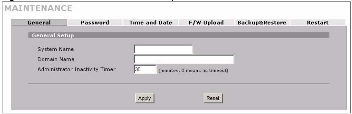
Figure 194 MAINTENANCE > General Setup
The following table describes the labels in this screen.
Table 113 MAINTENANCE > General Setup
| LABEL | DESCRIPTION |
| General Setup | |
| System Name | Choose a descriptive name for identification purposes. It is recommended you enter your computer's "Computer name" in this field. This name can be up to 30 alphanumeric characters long. Spaces are not allowed, but dashes "-" and underscores "-" are accepted. |
| Domain Name | The Domain Name entry is what is propagated to the DHCP clients on the LAN. If you leave this blank, the domain name obtained by DHCP from the ISP is used. While you must enter the host name (System Name), the domain name can be assigned from the ZyXEL Device via DHCP. Enter the domain name (if you know it) here. If you leave this field blank, the ISP may assign a domain name via DHCP. The domain name entered by you is given priority over the ISP assigned domain name. |
| Administrator Inactivity Timer | Type how many minutes a management session (via the web configurator) can be left idle before the session times out. The default is 5 minutes. After it times out you have to log in with your password again. Very long idle timeouts may have security risks. A value of "0" means a management session never times out, no matter how long it has been left idle (not recommended). |
| Apply | Click Apply to save your changes. |
| Reset | Click Reset to begin configuring this screen afresh. |
20.3 Configuring Password
Click MAINTENANCE > Password to open the following screen. Use this screen to change the ZyXEL Device's management password.
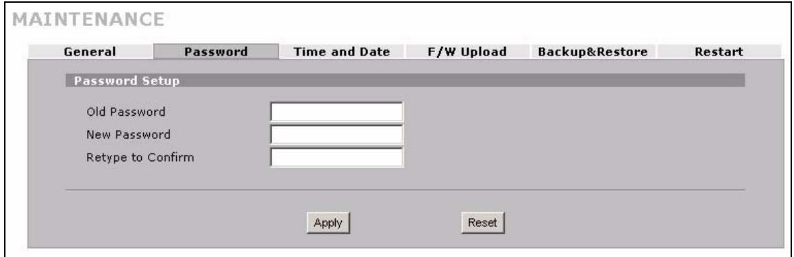
Figure 195 MAINTENANCE > Password
The following table describes the labels in this screen.
Table 114 MAINTENANCE > Password
| LABEL | DESCRIPTION |
| Old Password | Type the default password or the existing password you use to access the system in this field. If you forget the password, you may have to use the hardware RESET button. This restores the default password of 1234. |
| New Password | Type your new system password (up to 30 characters). Note that as you type a password, the screen displays a (*) for each character you type. |
| Retype to Confirm | Type the new password again for confirmation. |
| Apply | Click Apply to save your changes. |
| Reset | Click Reset to begin configuring this screen afresh. |
20.4 Time and Date
The ZyXEL Device's Real Time Chip (RTC) keeps track of the time and date. There is also a software mechanism to set the time manually or get the current time and date from an external server when you turn on your ZyXEL Device.
To change your ZyXEL Device's time and date, click MAINTENANCE > Time and Date. The screen appears as shown. Use this screen to configure the ZyXEL Device's time based on your local time zone.
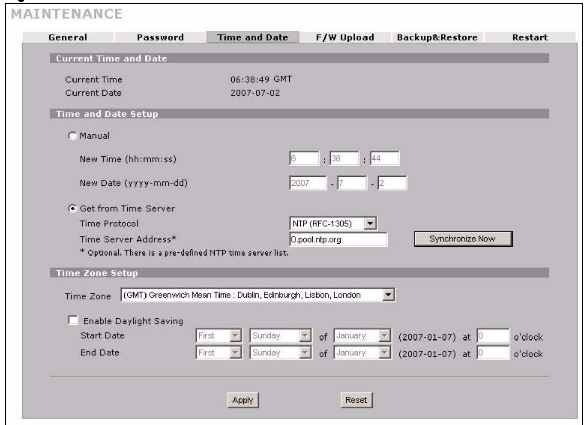
Figure 196 MAINTENANCE > Time and Date
The following table describes the labels in this screen.
Table 115 MAINTENANCE > Time and Date
| LABEL | DESCRIPTION |
| Current Time and Date | |
| Current Time | This field displays the ZyXEL Device's present time. |
| Current Date | This field displays the ZyXEL Device's present date. |
| Time and Date Setup | |
| Manual | Select this radio button to enter the time and date manually. If you configure a new time and date, Time Zone and Daylight Saving at the same time, the new time and date you entered has priority and the Time Zone and Daylight Saving settings do not affect it. |
| New Time (hh:mm:ss) | This field displays the last updated time from the time server or the last time configured manually. When you set Time and Date Setup to Manual, enter the new time in this field and then click Apply. |
| New Date (yyyy-mm-dd) | This field displays the last updated date from the time server or the last date configured manually. When you set Time and Date Setup to Manual, enter the new date in this field and then click Apply. |
| Get from Time Server | Select this radio button to have the ZyXEL Device get the time and date from the time server you specified below. |
| Time Protocol | Select the time service protocol that your time server uses. Not all time servers support all protocols, so you may have to check with your ISP/network administrator or use trial and error to find a protocol that works.The main difference between them is the format.Daytime (RFC 867) format is day/month/year/time zone of the server.Time (RFC 868) format displays a 4-byte integer giving the total number of seconds since 1970/1/1 at 0:0:0.The default, NTP (RFC 1305), is similar to Time (RFC 868). |
| Time Server Address | Enter the IP address or URL of your time server. Check with your ISP/network administrator if you are unsure of this information. |
| Synchronize Now | Click this button to have the ZyXEL Device get the time and date from a time server (see the Time Server Address field). This also saves your changes (including the time server address). |
| Time Zone Setup | |
| Time Zone | Choose the time zone of your location. This will set the time difference between your time zone and Greenwich Mean Time (GMT). |
| Enable Daylight Saving | Daylight saving is a period from late spring to early fall when many countries set their clocks ahead of normal local time by one hour to give more daytime light in the evening.Select this option if you use Daylight Saving Time. |
| Start Date | Configure the day and time when Daylight Saving Time starts if you selected Enable Daylight Saving. The o'clock field uses the 24 hour format. Here are a couple of examples:Daylight Saving Time starts in most parts of the United States on the second Sunday of March. Each time zone in the United States starts using Daylight Saving Time at 2 A.M. local time. So in the United States you would select Second, Sunday, March and type 2 in the o'clock field.Daylight Saving Time starts in the European Union on the last Sunday of March.All of the time zones in the European Union start using Daylight Saving Time at the same moment (1 A.M. GMT or UTC). So in the European Union you would select Last, Sunday, March. The time you type in the o'clock field depends on your time zone. In Germany for instance, you would type 2 because Germany's time zone is one hour ahead of GMT or UTC (GMT+1). |
| End Date | Configure the day and time when Daylight Saving Time ends if you selected Enable Daylight Saving. The o'clock field uses the 24 hour format. Here are a couple of examples:Daylight Saving Time ends in the United States on the first Sunday of November. Each time zone in the United States stops using Daylight Saving Time at 2 A.M. local time. So in the United States you would select First, Sunday, November and type 2 in the o'clock field.Daylight Saving Time ends in the European Union on the last Sunday of October.All of the time zones in the European Union stop using Daylight Saving Time at the same moment (1 A.M. GMT or UTC). So in the European Union you would select Last, Sunday, October. The time you type in the o'clock field depends on your time zone. In Germany for instance, you would type 2 because Germany's time zone is one hour ahead of GMT or UTC (GMT+1). |
| Apply | Click Apply to save your changes. |
| Reset | Click Reset to begin configuring this screen afresh. |
20.5 Pre-defined NTP Time Server Pools
When you turn on the ZyXEL Device for the first time, the date and time start at 2000-01-01 00:00:00. The ZyXEL Device then attempts to synchronize with an NTP time server from one of the 0.pool.ntp.org, 1.pool.ntp.org or 2.pool.ntp.org NTP time server pools. These are virtual clusters of time servers that use a round robin method to provide different NTP servers to clients.
The ZyXEL Device continues to use the NTP time server pools if you do not specify a time server or it cannot synchronize with the time server you specified.

The ZyXEL Device can use the NTP time server pools regardless of the time protocol you select.
When the ZyXEL Device uses the NTP time server pools, it randomly selects one pool and tries to synchronize with a server in it. If the synchronization fails, then the ZyXEL Device goes through the rest of the list in order from the first one tried until either it is successful or all the pre-defined NTP time server pools have been tried.
20.5.1 Resetting the Time
The ZyXEL Device resets the time in the following instances:
- When you click Synchronize Now.
- On saving your changes.
- When the ZyXEL Device starts up.
24-hour intervals after starting.
20.5.2 Time Server Synchronization
Click the Synchronize Now button to get the time and date from the predefined time server or the time server you specified in the Time Server Address field.
When the System Time and Date Synchronization in Process screen appears, wait up to one minute.
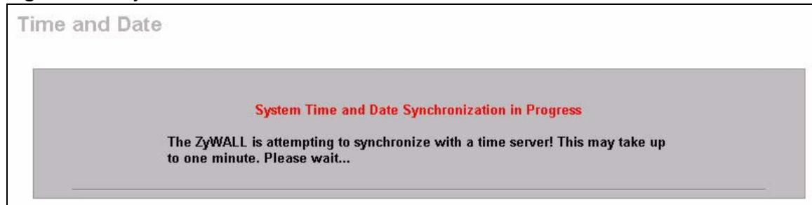
Figure 197 Synchronization in Process
Click the Return button to go back to the Time and Date screen after the time and date is updated successfully.
Figure 198 Synchronization is Successful
If the update was not successful, the following screen appears. Click Return to go back to the Time and Date screen.
Figure 199 Synchronization Fail
20.6 F/W Upload Screen
Find firmware at www.zyxel.com in a file that (usually) uses the system model name with a .bin extension, for example, "NBG410W3G.bin". The upload process uses HTTP (Hypertext Transfer Protocol) and may take up to two minutes. After a successful upload, the system will reboot.
Click MAINTENANCE > F/W UPGoad. Follow the instructions in this screen to upload firmware to your ZyXEL Device.

Only upload firmware for your specific model!
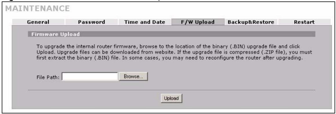
Figure 200 MAINTENANCE > Firmware Upload
The following table describes the labels in this screen.
Table 116 MAINTENANCE > Firmware Upload
| LABEL | DESCRIPTION |
| File Path | Type in the location of the file you want to upload in this field or click Browse ... to find it. |
| Browse... | Click Browse... to find the .bin file you want to upload. Remember that you must decompress compressed (.zip) files before you can upload them. |
| Upload | Click Upload to begin the upload process. This process may take up to two minutes. |

Do not turn off the ZyXEL Device while firmware upload is in progress!
After you see the Firmware Upload in Process screen, wait two minutes before logging into the ZyXEL Device again.
Figure 201 Firmware Upload In Process
The ZyXEL Device automatically restarts in this time causing a temporary network disconnect. In some operating systems, you may see the following icon on your desktop.
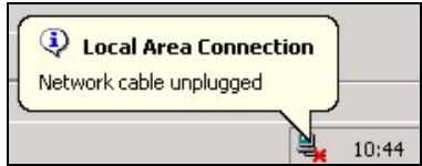
Figure 202 Network Temporarily Disconnected
After two minutes, log in again and check your new firmware version in the HOME screen.
If the upload was not successful, the following screen will appear. Click Return to go back to the F/W Upload screen.
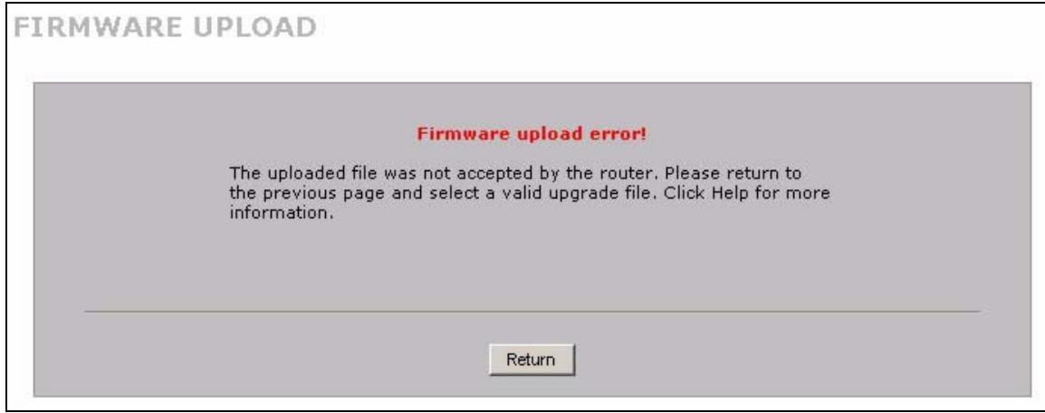
Figure 203 Firmware Upload Error
20.7 Backup and Restore
Click MAINTENANCE > Backup & Restore. Information related to factory defaults, backup configuration, and restoring configuration appears as shown next.
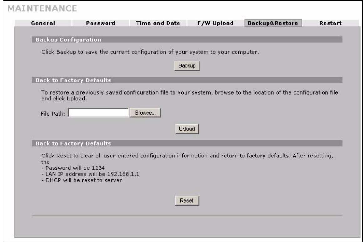
Figure 204 MAINTENANCE > Backup and Restore
20.7.1 Backup Configuration
Backup configuration allows you to back up (save) the ZyXEL Device's current configuration to a file on your computer. Once your ZyXEL Device is configured and functioning properly, it is highly recommended that you back up your configuration file before making configuration changes. The backup configuration file will be useful in case you need to return to your previous settings.
Click Backup to save the ZyXEL Device's current configuration to your computer.
20.7.2 Restore Configuration
Load a configuration file from your computer to your ZyXEL Device.
Table 117 Restore Configuration
| LABEL | DESCRIPTION |
| File Path | Type in the location of the file you want to upload in this field or click Browse ... to find it. |
| Browse... | Click Browse... to find the file you want to upload. Remember that you must decompress compressed (.ZIP) files before you can upload them. |
| Upload | Click Upload to begin the upload process. |

Do not turn off the ZyXEL Device while configuration file upload is in progress.
After you see a "restore configuration successful" screen, you must then wait one minute before logging into the ZyXEL Device again.
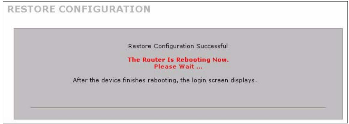
Figure 205 Configuration Upload Successful
The ZyXEL Device automatically restarts in this time causing a temporary network disconnect. In some operating systems, you may see the following icon on your desktop.
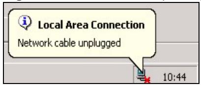
Figure 206 Network Temporarily Disconnected
If you uploaded the default configuration file you may need to change the IP address of your computer to be in the same subnet as that of the default device IP address (192.168.1.1). See your Quick Start Guide for details on how to set up your computer's IP address.
If the upload was not successful, the following screen will appear. Click Return to go back to the Configuration screen.
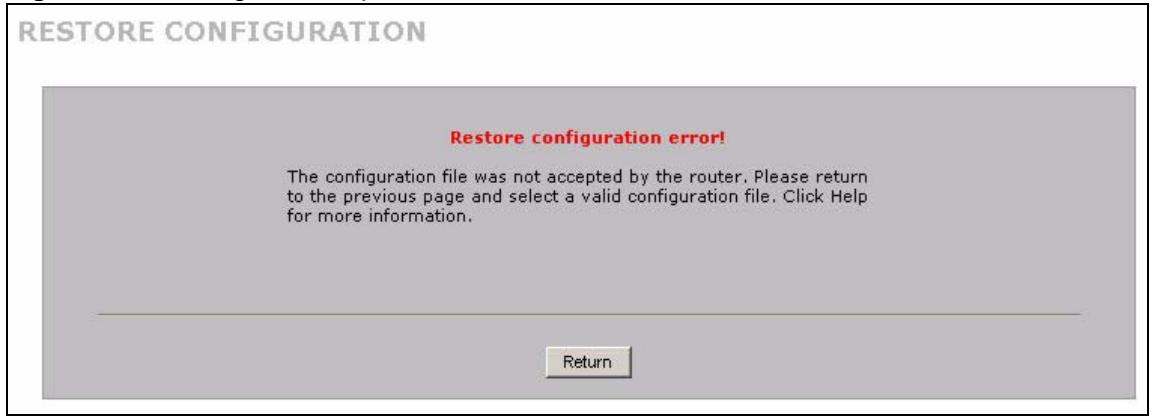
Figure 207 Configuration Upload Error
20.7.3 Back to Factory Defaults
Click the Reset button to clear all user-entered configuration information and return the ZyXEL Device to its factory defaults as shown on the screen. The following warning screen appears.
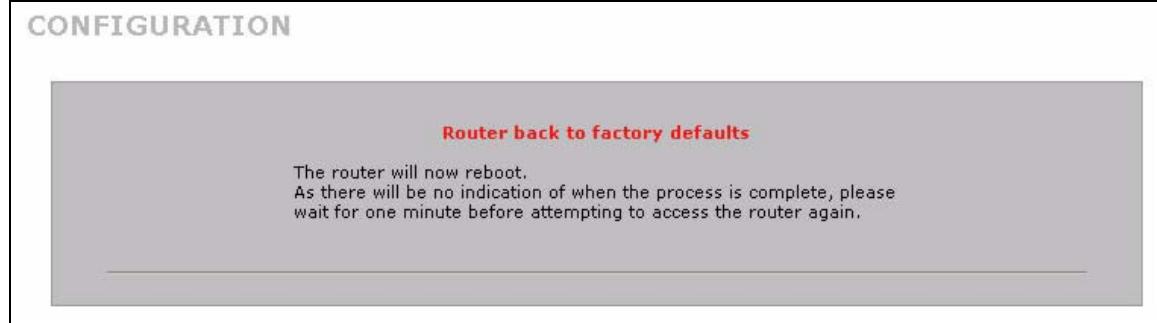
Figure 208 Reset Warning Message
You can also press the hardware RESET button to reset the factory defaults of your ZyXEL Device. Refer to Section 2.3 on page 45 for more information on the RESET button.
20.8 Restart Screen
System restart allows you to reboot the ZyXEL Device without turning the power off.
Click MAINTENANCE > Restart. Click Restart to have the ZyXEL Device reboot. Restart is different to reset; (see Section 20.7.3 on page 335) reset returns the device to its default configuration.
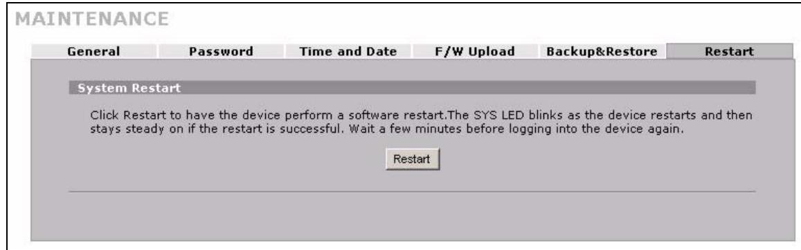
Figure 209 MAINTENANCE > Restart
PART VII
Troubleshooting and Specifications
Troubleshooting (339)
Product Specifications (345)
Troubleshooting
This chapter offers some suggestions to solve problems you might encounter. The potential problems are divided into the following categories.
- Power, Hardware Connections, and LEDs
ZyXEL Device Access and Login - Internet Access
3G Connection
21.1 Power, Hardware Connections, and LEDs

The ZyXEL Device does not turn on. None of the LEDs turn on.
1 Make sure the ZyXEL Device is turned on.
2 Make sure you are using the power adaptor or cord included with the ZyXEL Device.
3 Make sure the power adaptor is connected to the ZyXEL Device and plugged in to an appropriate power source. Make sure the power source is turned on.
4 Turn the ZyXEL Device off and on or disconnect and re-connect the power adaptor to the ZyXEL Device.
5 If the problem continues, contact the vendor.

One of the LEDs does not behave as expected.
1 Make sure you understand the normal behavior of the LED. See Section 1.5.1 on page 39.
2 Check the hardware connections. See the Quick Start Guide.
3 Inspect your cables for damage. Contact the vendor to replace any damaged cables.
4 Turn the ZyXEL Device off and on or disconnect and re-connect the power adaptor to the ZyXEL Device.
5 If the problem continues, contact the vendor.
21.2 ZyXEL Device Access and Login

I forgot the LAN IP address for the ZyXEL Device.
1 The default LAN IP address is 192.168.1.1.
2 Use the console port to log in to the ZyXEL Device.
3 If you changed the IP address and have forgotten it, you might get the IP address of the ZyXEL Device by looking up the IP address of the default gateway for your computer. To do this in most Windows computers, click Start > Run, enter cmd, and then enter ipconfig. The IP address of the Default Gateway might be the IP address of the ZyXEL Device (it depends on the network), so enter this IP address in your Internet browser.
4 If this does not work, you have to reset the device to its factory defaults. See Section 2.3 on page 45.

I forgot the password.
1 The default password is 1234.
2 If this does not work, you have to reset the device to its factory defaults. See Section 2.3 on page 45.

I cannot see or access the Login screen in the web configurator.
1 Make sure you are using the correct IP address.
- The default LAN IP address is 192.168.1.1.
- Use the ZyXEL Device's LAN IP address when configuring from the LAN.
- Use the ZyXEL Device's WAN IP address when configuring from the WAN.
- If you changed the LAN IP address (Section 5.7 on page 104), use the new IP address.
- If you changed the LAN IP address and have forgotten it, see the troubleshooting suggestions for I forgot the LAN IP address for the ZyXEL Device.
2 Check the hardware connections, and make sure the LEDs are behaving as expected. See the Quick Start Guide and Section 1.5.1 on page 39.
3 Make sure your Internet browser does not block pop-up windows and has JavaScript and Java enabled. See Appendix A on page 353.
4 Make sure your computer's Ethernet adapter is installed and functioning properly.
5 Make sure your computer is in the same subnet as the ZyXEL Device. (If you know that there are routers between your computer and the ZyXEL Device, skip this step.)
- If there is a DHCP server on your network, make sure your computer is using a dynamic IP address. See Appendix B on page 361. Your ZyXEL Device is a DHCP server by default.
6 Reset the device to its factory defaults, and try to access the ZyXEL Device with the default IP address. See Section 2.3 on page 45.
7 If the problem continues, contact the network administrator or vendor, or try one of the advanced suggestions.
Advanced Suggestions
- Try to access the ZyXEL Device using another service, such as Telnet. If you can access the ZyXEL Device, check the remote management settings, and firewall rules to find out why the ZyXEL Device does not respond to HTTP.
- If your computer is connected to the WAN port or is connected wirelessly, use a computer that is connected to a LAN port.
- You may also need to clear your Internet browser's cache. In Internet Explorer, click Tools and then Internet Options to open the Internet Options screen.
In the General tab, click Delete Files. In the pop-up window, select the Delete all offline content check box and click OK. Click OK in the Internet Options screen to close it.
- If you disconnect your computer from one device and connect it to another device that has the same IP address, your computer's ARP (Address Resolution Protocol) table may contain an entry that maps the management IP address to the previous device's MAC address).
In Windows, use arp -d at the command prompt to delete all entries in your computer's ARP table.

I can see the Login screen, but I cannot log in to the ZyXEL Device.
1 Make sure you have entered the password correctly. The default password is 1234. These fields are case-sensitive, so make sure [Caps Lock] is not on.
2 You cannot log in to the web configurator while someone is using Telnet, or the console port to access the ZyXEL Device. Log out of the ZyXEL Device in the other session, or ask the person who is logged in to log out.
3 Turn the ZyXEL Device off and on or disconnect and re-connect the power adaptor or cord to the ZyXEL Device.
4 If this does not work, you have to reset the device to its factory defaults. See Section 2.3 on page 45.

I cannot Telnet to the ZyXEL Device.
See the troubleshooting suggestions for I cannot see or access the Login screen in the web configurator. Ignore the suggestions about your browser.

I cannot use FTP to upload / download the configuration file. / I cannot use FTP to upload new firmware.
See the troubleshooting suggestions for I cannot see or access the Login screen in the web configurator. Ignore the suggestions about your browser.
21.3 Internet Access

I cannot get a WAN IP address from the ISP.
1 The ISP provides the WAN IP address after authenticating you. Authentication may be through the user name and password, the MAC address or the host name.
The username and password apply to PPPoE and PPPoA encapsulation only. Make sure that you have entered the correct Service Type, User Name and Password (be sure to use the correct casing). Refer to the WAN setup chapter (web configurator).
2 Disconnect all the cables from your device, and follow the directions in the Quick Start Guide again.
3 If the problem continues, contact your ISP.

I cannot access the Internet.
1 Check the hardware connections, and make sure the LEDs are behaving as expected. See the Quick Start Guide and Section 1.5.1 on page 39.
2 Make sure you entered your ISP account information correctly in the wizard, or WAN screen. These fields are case-sensitive, so make sure [Caps Lock] is not on.
3 If you are trying to access the Internet wirelessly, make sure the wireless settings in the wireless client are the same as the settings in the AP.
4 Disconnect all the cables from your device, and follow the directions in the Quick Start Guide again.
5 If the problem continues, contact your ISP.

I cannot access the Internet anymore. I had access to the Internet (with the ZyXEL Device), but my Internet connection is not available anymore.
1 Check the hardware connections, and make sure the LEDs are behaving as expected. See the Quick Start Guide and Section 1.5.1 on page 39.
2 If you use PPPoA or PPPoE encapsulation, check the idle time-out setting. Refer to the Chapter 6 on page 111.
3 Reboot the ZyXEL Device.
4 If the problem continues, contact your ISP.

The Internet connection is slow or intermittent.
1 There might be a lot of traffic on the network. Look at the LEDs, and check Section 1.5.1 on page 39. If the ZyXEL Device is sending or receiving a lot of information, try closing some programs that use the Internet, especially peer-to-peer applications.
2 Check the signal strength. If the signal strength is low, try moving the ZyXEL Device closer to the AP if possible, and look around to see if there are any devices that might be interfering with the wireless network (for example, microwaves, other wireless networks, and so on).
3 Reboot the ZyXEL Device.
4 If the problem continues, contact the network administrator or vendor, or try one of the advanced suggestions.
21.4 3G Connection

The 3G OPERATION LED is off.
- Check the 3G SIM card is correctly inserted. See the Quick Start Guide for instructions.
- Check your 3G settings are correctly configured in the 3G screen, including your PIN, user name and password (if required) and telephone number (required). Use the information provided by your 3G ISP for your 3G user account.
- If you have used a different 3G SIM card with this device previously, the 3G card may have stored the settings for your previous SIM card. Ensure you have entered the correct settings for your current SIM card and click Apply.
- Check that you have selected the correct 3G interface in the 3G (WAN2) screen.
- Check the HOME screen. An error message displays in the HOME screen if you have entered the incorrect PIN in the 3G (WAN2) screen.
- Check your 3G connection status in the HOME screen. If WAN2 has no IP address, click Dial to request your 3G ISP for an IP address.
- If you are using an external 3G USB module, check that it is correctly attached.
- Check your 3G account status with your 3G service provider.

The 3G SIGNAL STRENGTH LED shows the 3G signal is weak or not available.
- Check that your 3G service provider has coverage in your area.
- Check that in the 3G (WAN2) screen you have selected the correct 3G service for your area. In some areas certain kinds of 3G may not be available.
- Move the ZyXEL Device away from any structures such as large buildings or tunnels that may be blocking the 3G signal.
- Move the ZyXEL Device away from devices that cause radio signal interference, such as microwave ovens and high voltage power lines.
- Check that the ZyXEL Device's antenna is fully extended and is pointing upwards.

The 3G OPERATION LED is on but my 3G connection is slow or non-existent.
- Check that WAN2 has an IP address in the HOME page. Click Dial (several times if necessary) to obtain a WAN2 IP address.
- Try moving to an area with better reception. If the signal quality is poor, the 3G modem will time out before obtaining an IP address.
- Check that you have enabled NAT in the 3G (WAN2) screen.
-
Actual download speeds usually differ from maximum advertised speeds. Typical data rates are as follows. If your average download speeds are much lower than the typical data rates given below, check the 3G SIGNAL STRENGTH LED.
-
If the 3G SIGNAL STRENGTH LED shows a weak signal, follows\ the suggestions given in The 3G SIGNAL STRENGTH LED shows the 3G signal is weak or not available.
- If it shows a strong signal, contact your 3G service provider for more help.
Table 118 Typical 3G transmission speeds
| PACKET DATA SERVICE | THEORETICAL MAXIMUM DATA RATE | TYPICAL DATA RATE | |
| EDGE | Upload | 236 kbps | 100~130 kbps |
| Download | 236 kbps | 100~130 kbps | |
| UMTS | Upload | 384 kbps | 100~300 kbps |
| Download | 384 kbps | 100~300 kbps | |
| HSDPA | Upload | 384 kbps | 100~300 kbps |
| Download | 3.6 Mbps | Up to 2 Mbps | |
Product Specifications
This chapter gives details about your ZyXEL Device's hardware and firmware features.
22.1 General ZyXEL Device Specifications
The following tables summarize the ZyXEL Device's hardware and firmware features.
Table 119 Hardware Specifications
| Dimensions | 190 (W) x 150 (D) x 33 (H) mm |
| Weight | 380 g |
| Power Specification | 12V DC 1.5 A |
| Ethernet Interface | |
| LAN/DMZ | Four LAN/DMZ auto-negotiating, auto MDI/MDI-X 10/100 Mbps RJ-45 Ethernet ports. |
| WAN | One auto-negotiating, auto MDI/MDI-X 10/100 Mbps RJ-45 Ethernet port. |
| Reset Button | Restores factory default settings. |
| Internal 3G module | SierraWireless MC8775 (NBG410W3G only) |
| USB slot | For installation of a 3G USB dongle. Supported models include: Huawei E220/E270 |
| SIM Card Slot | For installing a 3G SIM card (NBG410W3G only). |
| Antenna | NBG410W3G: One internal 3.6 dBi antenna One external 850/900/1800/1900/2100 MHz 3G antenna NBG412W3G: One external 3.6 dBi antenna |
| Distance between the centers of the holes (for wall mounting) on the device's back. | 165.75 mm |
| Screw size for wall-mounting | M 4*10 Tap Screw, see Figure 210 on page 348. |
| Operation Environment | Temperature: 0° C ~ 40° C Humidity: 20% ~ 95% (non-condensing) |
| Storage Environment | Temperature: -30° ~ 60° C Humidity: 20% ~ 95% RH (non-condensing) |
| Certifications | EMC: FCC Part 15 Class B, CE-EMC Class B, C-Tick Class B Safety: CSA International, (UL60950-1, CSA60950-1, EN60950-1, IEC60950-1) |
Table 120 Firmware Specifications
| FEATURE | DESCRIPTION |
| Default IP Address | 192.168.1.1 |
| Default Subnet Mask | 255.255.255.0 (24 bits) |
| Default Password | 1234 |
| Default DHCP Pool | 192.168.1.33 to 192.168.1.160 |
| Device Management | Use the web configurator to easily configure the rich range of features on the ZyxEL Device. |
| 3G (2.5G) Functionality | Supports UMTS, HSDPA, UMTS, EDGE 3G and GPRS 2.5G standards. |
| Wi-Fi Functionality | Allows the IEEE 802.11b and/or IEEE 802.11g wireless clients to connect to the ZyxEL Device wirelessly. Enable wireless security (WEP, WPA(2), WPA(2)-PSK) and/or MAC filtering to protect your wireless network. |
| Firmware Upgrade | Download new firmware (when available) from the ZyxEL web site and use the web configurator, an FTP or a TFTP tool to put it on the ZyxEL Device.Note: Only upload firmware for your specific model! |
| Configuration Backup & Restoration | Make a copy of the ZyxEL Device's configuration. You can put it back on the ZyxEL Device later if you decide to revert back to an earlier configuration. |
| Network Address Translation (NAT) | Each computer on your network must have its own unique IP address.Use NAT to convert your public IP address(es) to multiple private IP addresses for the computers on your network. |
| Port Forwarding | If you have a server (mail or web server for example) on your network, you can use this feature to let people access it from the Internet. |
| DHCP (Dynamic Host Configuration Protocol) | Use this feature to have the ZyxEL Device assign IP addresses, an IP default gateway and DNS servers to computers on your network. |
| Dynamic DNS Support | With Dynamic DNS (Domain Name System) support, you can use a fixed URL, www.zyxel.com for example, with a dynamic IP address. You must register for this service with a Dynamic DNS service provider. |
| IP Multicast | IP multicast is used to send traffic to a specific group of computers. The ZyxEL Device supports versions 1 and 2 of IGMP (Internet Group Management Protocol) used to join multicast groups (see RFC 2236). |
| IP Alias | IP alias allows you to subdivide a physical network into logical networks over the same Ethernet interface with the ZyxEL Device itself as the gateway for each subnet. |
| Time and Date | Get the current time and date from an external server when you turn on your ZyxEL Device. You can also set the time manually. These dates and times are then used in logs. |
| Logging and Tracing | Use packet tracing and logs for troubleshooting. You can send logs from the ZyxEL Device to an external syslog server. |
| PPPoe | PPPoe mimics a dial-up Internet access connection. |
| PPTP Encapsulation | Point-to-Point Tunneling Protocol (PPTP) enables secure transfer of data through a Virtual Private Network (VPN). The ZyxEL Device supports one PPTP connection at a time. |
| Universal Plug and Play (UPnP) | A UPnP-enabled device can dynamically join a network, obtain an IP address and convey its capabilities to other devices on the network. |
Table 120 Firmware Specifications
| FEATURE | DESCRIPTION |
| RoadRunner Support | The ZyXEL Device supports Time Warner's RoadRunner Service in addition to standard cable modem services. |
| Firewall | You can configure firewall on the ZyXEL Device for secure Internet access. When the firewall is on, by default, all incoming traffic from the Internet to your network is blocked unless it is initiated from your network. This means that probes from the outside to your network are not allowed, but you can safely browse the Internet and download files for example. |
| Remote Management | This allows you to decide whether a service (HTTP or FTP traffic for example) from a computer on a network (LAN or WAN for example) can access the ZyXEL Device. |
Table 121 Feature Specifications
| FEATURE | SPECIFICATION |
| Local User Database Entries | 32 |
| Static DHCP Table Entries | 32 |
| Static Routes | 30 |
| Concurrent Sessions (NAT sessions) | 3,000 |
| Address Mapping Rules | 10 |
| Port Forwarding Rules | 20 |
| DNS Address Record Entries | 30 |
| DNS Name Server Record Entries | 16 |
| Firewall Throughput (with NAT) | 12 Mbps |
| Output Power (Maximum) | IEEE 802.11b: 16 dBm at 11 Mbps CCK, QPSK, BPSK IEEE 802.11g: 13 dBm at 54 Mbps OFDM |
22.2 Wall-mounting Instructions
Complete the following steps to hang your ZyXEL Device on a wall.

See Table 119 on page 345 for the size of screws to use and how far apart to place them.
1 Select a position free of obstructions on a sturdy wall.
2 Drill two holes for the screws.

Be careful to avoid damaging pipes or cables located inside the wall when drilling holes for the screws.
3 Do not insert the screws all the way into the wall. Leave a small gap of about 0.5cm between the heads of the screws and the wall.
4 Make sure the screws are snugly fastened to the wall. They need to hold the weight of the ZyXEL Device with the connection cables.
5 Align the holes on the back of the ZyXEL Device with the screws on the wall. Hang the ZyXEL Device on the screws.

Figure 210 Wall-mounting Example
The following are dimensions of an M4 tap screw and masonry plug used for wall mounting. All measurements are in millimeters (mm).
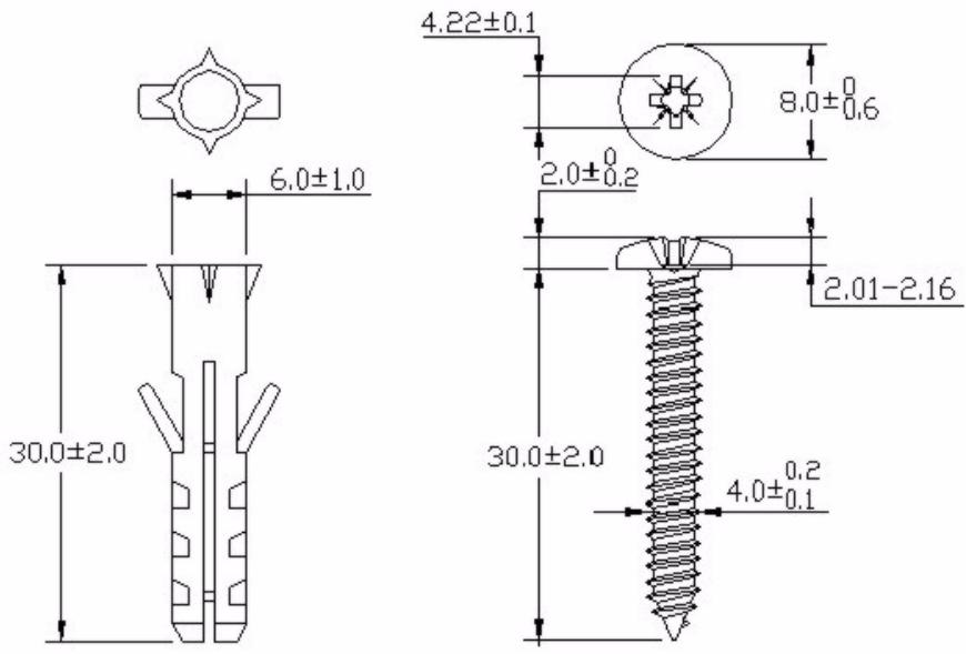
Figure 211 Masonry Plug and M4 Tap Screw
22.3 Power Adaptor Specifications
| NORTH AMERICAN PLUG STANDARDS | |
| AC POWER ADAPTOR MODEL | PSA18R-120P (ZA)-R |
| INPUT POWER | 100-240VAC, 50/60HZ, 0.5A |
| OUTPUT POWER | 12VDC, 1.5A |
| POWER CONSUMPTION | 18 W MAX. |
| SAFETY STANDARDS | UL, CUL (UL 60950-1 FIRST EDITIONCSA C22.2 NO. 60950-1-03 1ST.) |
| EUROPEAN PLUG STANDARDS | |
| AC POWER ADAPTOR MODEL | PSA18R-120P (ZE)-R |
| INPUT POWER | 100-240VAC, 50/60HZ, 0.5A |
| OUTPUT POWER | 12VDC, 1.5A |
| POWER CONSUMPTION | 18 W MAX. |
| SAFETY STANDARDS | TUV, CE (EN 60950-1) |
| UNITED KINGDOM PLUG STANDARDS | |
| AC POWER ADAPTOR MODEL | PSA18R-120P (ZK)-R |
| INPUT POWER | 100-240VAC, 50/60HZ, 0.5A |
| OUTPUT POWER | 12VDC, 1.5A |
| POWER CONSUMPTION | 18 W MAX. |
| SAFETY STANDARDS | TUV (BS EN 60950-1) |
PART VIII
Appendices and Index

The appendices provide general information. Some details may not apply to your ZyXEL Device.
Pop-up Windows, JavaScript and Java Permissions (353)
Setting up Your Computer's IP Address (361)
IP Addresses and Subnetting (377)
Common Services (385)
Wireless LANs (389)
Importing Certificates (403)
Legal Information (415)
Customer Support (419)
Index (425)
Pop-up Windows, JavaScript and Java Permissions
In order to use the web configurator you need to allow:
- Web browser pop-up windows from your device.
- JavaScripts (enabled by default).
- Java permissions (enabled by default).

Internet Explorer 6 screens are used here. Screens for other Internet Explorer versions may vary.
Internet Explorer Pop-up Blockers
You may have to disable pop-up blocking to log into your device.
Either disable pop-up blocking (enabled by default in Windows XP SP (Service Pack) 2) or allow pop-up blocking and create an exception for your device's IP address.
Disable Pop-up Blockers
1 In Internet Explorer, select Tools, Pop-up Blocker and then select Turn Off Pop-up Blocker.
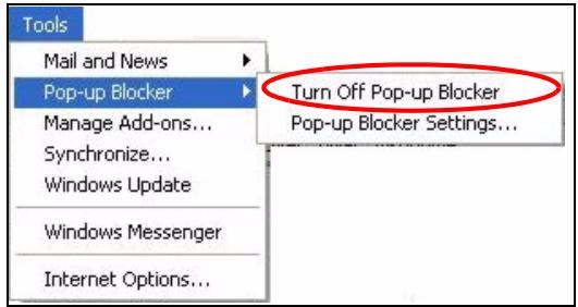
Figure 212 Pop-up Blocker
You can also check if pop-up blocking is disabled in the Pop-up Blocker section in the Privacy tab.
1 In Internet Explorer, select Tools, Internet Options, Privacy.
2 Clear the Block pop-ups check box in the Pop-up Blocker section of the screen. This disables any web pop-up blockers you may have enabled.
Figure 213 Internet Options: Privacy
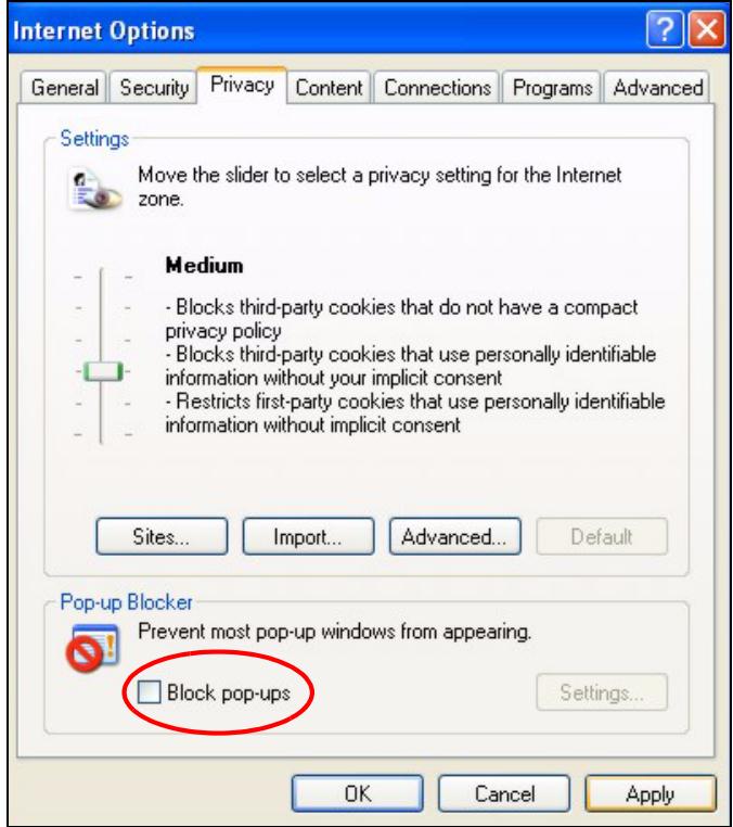
3 Click Apply to save this setting.
Enable Pop-up Blockers with Exceptions
Alternatively, if you only want to allow pop-up windows from your device, see the following steps.
1 In Internet Explorer, select Tools, Internet Options and then the Privacy tab.
2 Select Settings...to open the Pop-up Blocker Settings screen.
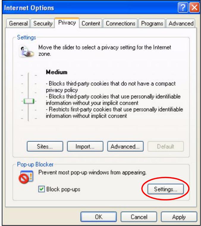
Figure 214 Internet Options: Privacy
3 Type the IP address of your device (the web page that you do not want to have blocked) with the prefix "http://". For example, http://192.168.167.1.
4 Click Add to move the IP address to the list of Allowed sites.
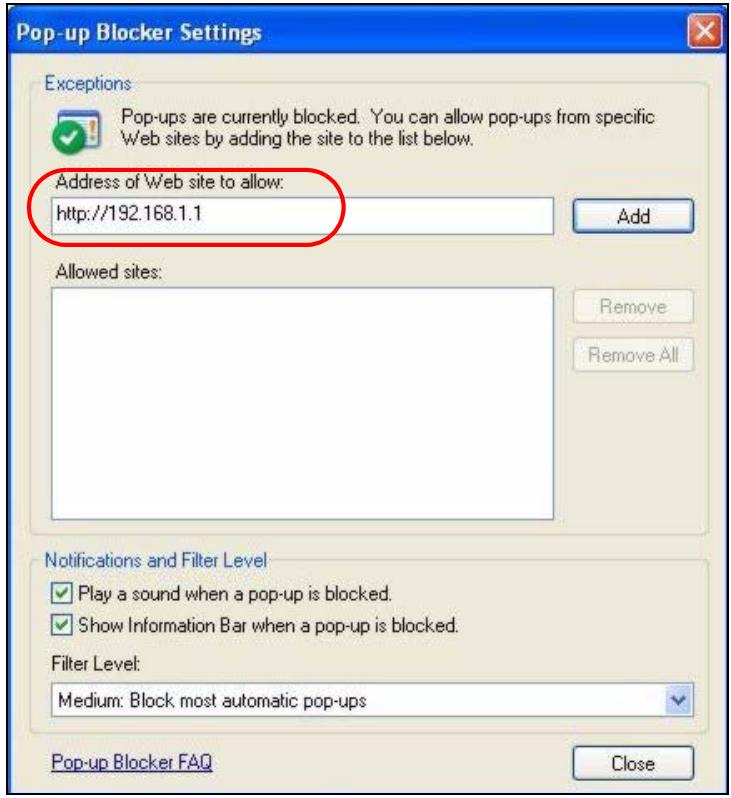
Figure 215 Pop-up Blocker Settings
5 Click Close to return to the Privacy screen.
6 Click Apply to save this setting.
JavaScript
If pages of the web configurator do not display properly in Internet Explorer, check that JavaScripts are allowed.
1 In Internet Explorer, click Tools, Internet Options and then the Security tab.
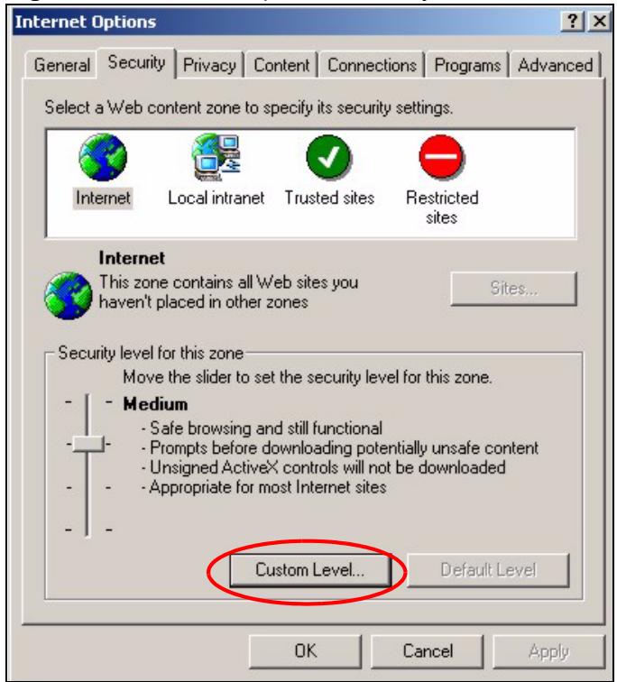
Figure 216 Internet Options: Security
2 Click the Custom Level... button.
3 Scroll down to Scripting.
4 Under Active scripting make sure that Enable is selected (the default).
5 Under Scripting of Java applets make sure that Enable is selected (the default).
6 Click OK to close the window.
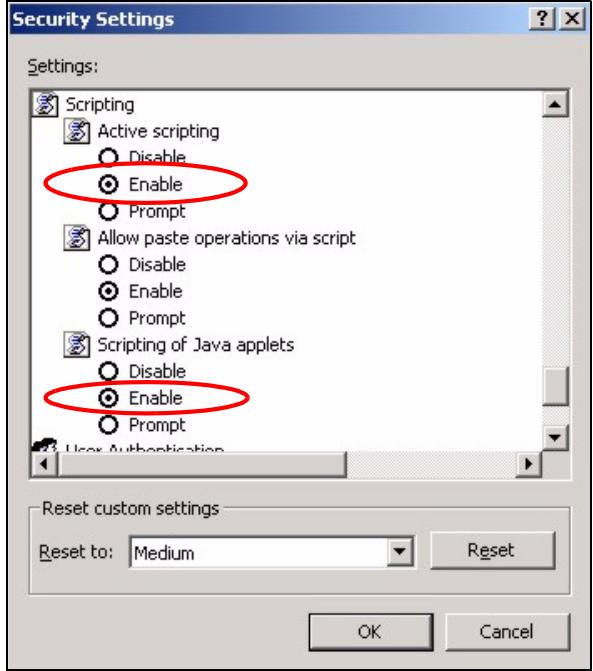
Figure 217 Security Settings - Java Scripting
Java Permissions
1 From Internet Explorer, click Tools, Internet Options and then the Security tab.
2 Click the Custom Level... button.
3 Scroll down to Microsoft VM.
4 Under Java permissions make sure that a safety level is selected.
5 Click OK to close the window.
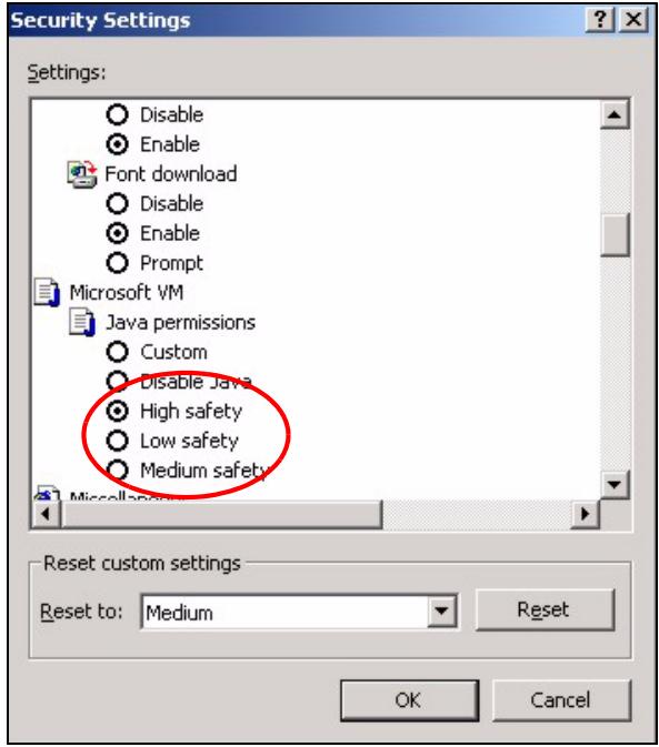
Figure 218 Security Settings - Java
JAVA (Sun)
1 From Internet Explorer, click Tools, Internet Options and then the Advanced tab.
2 Make sure that Use Java 2 for
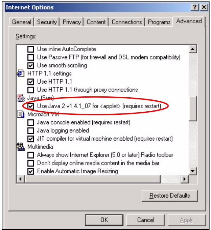
Figure 219 Java (Sun)
Mozilla Firefox
Mozilla Firefox 2.0 screens are used here. Screens for other versions may vary.
You can enable Java, Javascrits and pop-ups in one screen. Click Tools, then click Options in the screen that appears.
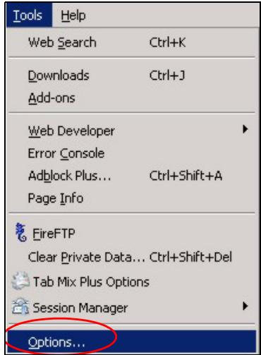
Figure 220 Mozilla Firefox: Tools > Options
Click Content to show the screen below. Select the check boxes as shown in the following screen.
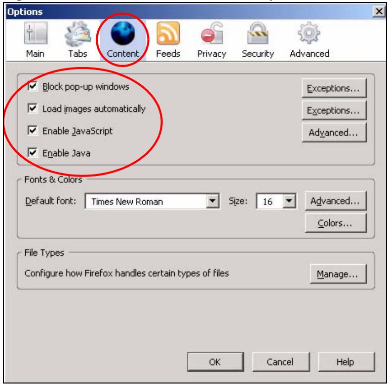
Figure 221 Mozilla Firefox Content Security
Setting up Your Computer’s IP Address
All computers must have a 10M or 100M Ethernet adapter card and TCP/IP installed.
Windows 95/98/Me/NT/2000/XP, Macintosh OS 7 and later operating systems and all versions of UNIX/LINUX include the software components you need to install and use TCP/IP on your computer. Windows 3.1 requires the purchase of a third-party TCP/IP application package.
TCP/IP should already be installed on computers using Windows NT/2000/XP, Macintosh OS 7 and later operating systems.
After the appropriate TCP/IP components are installed, configure the TCP/IP settings in order to "communicate" with your network.
If you manually assign IP information instead of using dynamic assignment, make sure that your computers have IP addresses that place them in the same subnet as the ZyXEL Device's LAN port.
Windows 95/98/Me
Click Start, Settings, Control Panel and double-click the Network icon to open the Network window.
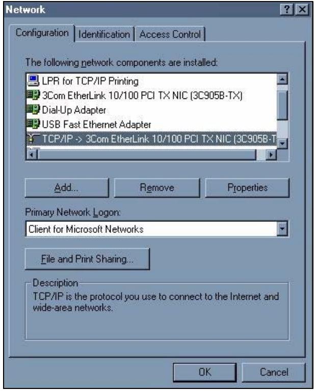
Figure 222 Windows 95/98/Me: Network: Configuration
Installing Components
The Network window Configuration tab displays a list of installed components. You need a network adapter, the TCP/IP protocol and Client for Microsoft Networks.
If you need the adapter:
1 In the Network window, click Add.
2 Select Adapter and then click Add.
3 Select the manufacturer and model of your network adapter and then click OK.
If you need TCP/IP:
1 In the Network window, click Add.
2 Select Protocol and then click Add.
3 Select Microsoft from the list of manufacturers.
4 Select TCP/IP from the list of network protocols and then click OK.
If you need Client for Microsoft Networks:
1 Click Add.
2 Select Client and then click Add.
3 Select Microsoft from the list of manufacturers.
4 Select Client for Microsoft Networks from the list of network clients and then click OK.
5 Restart your computer so the changes you made take effect.
Configuring
1 In the Network window Configuration tab, select your network adapter's TCP/IP entry and click Properties
2 Click the IP Address tab.
- If your IP address is dynamic, select Obtain an IP address automatically.
- If you have a static IP address, select Specify an IP address and type your information into the IP Address and Subnet Mask fields.
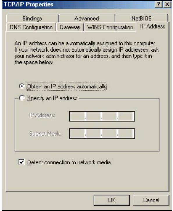
Figure 223 Windows 95/98/Me: TCP/IP Properties: IP Address
3 Click the DNS Configuration tab.
- If you do not know your DNS information, select Disable DNS.
- If you know your DNS information, select Enable DNS and type the information in the fields below (you may not need to fill them all in).
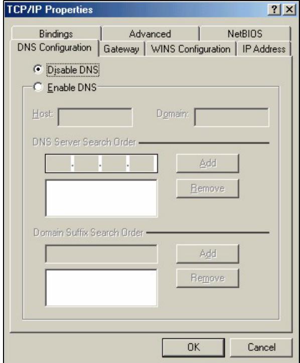
Figure 224 Windows 95/98/Me: TCP/IP Properties: DNS Configuration
4 Click the Gateway tab.
- If you do not know your gateway's IP address, remove previously installed gateways.
- If you have a gateway IP address, type it in the New gateway field and click Add.
5 Click OK to save and close the TCP/IP Properties window.
6 Click OK to close the Network window. Insert the Windows CD if prompted.
7 Turn on your ZyXEL Device and restart your computer when prompted.
Verifying Settings
1 Click Start and then Run.
2 In the Run window, type "winipcfg" and then click OK to open the IP Configuration window.
3 Select your network adapter. You should see your computer's IP address, subnet mask and default gateway.
Windows 2000/NT/XP
The following example figures use the default Windows XP GUI theme.
1 Click start (Start in Windows 2000/NT), Settings, Control Panel.
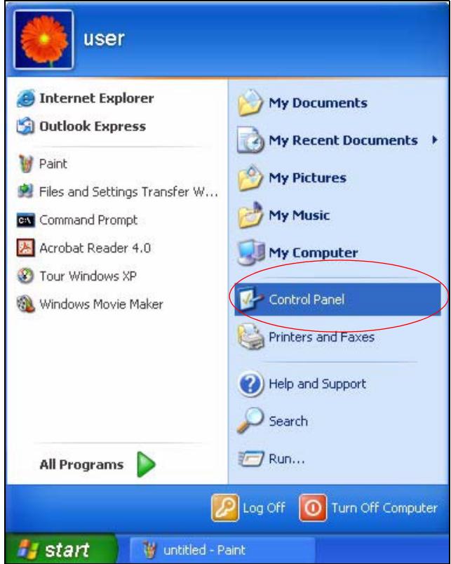
Figure 225 Windows XP: Start Menu
2 In the Control Panel, double-click Network Connections (Network and Dial-up Connections in Windows 2000/NT).
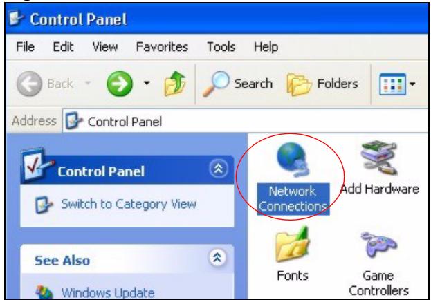
Figure 226 Windows XP: Control Panel
3 Right-click Local Area Connection and then click Properties.
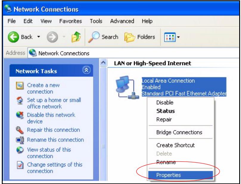
Figure 227 Windows XP: Control Panel: Network Connections: Properties
4 Select Internet Protocol (TCP/IP) (under the General tab in Win XP) and then click Properties.
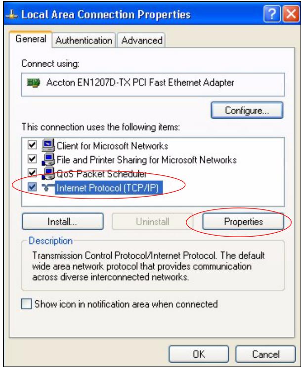
Figure 228 Windows XP: Local Area Connection Properties
5 The Internet Protocol TCP/IP Properties window opens (the General tab in Windows XP).
- If you have a dynamic IP address click Obtain an IP address automatically.
- If you have a static IP address click Use the following IP Address and fill in the IP address, Subnet mask, and Default gateway fields.
- Click Advanced.
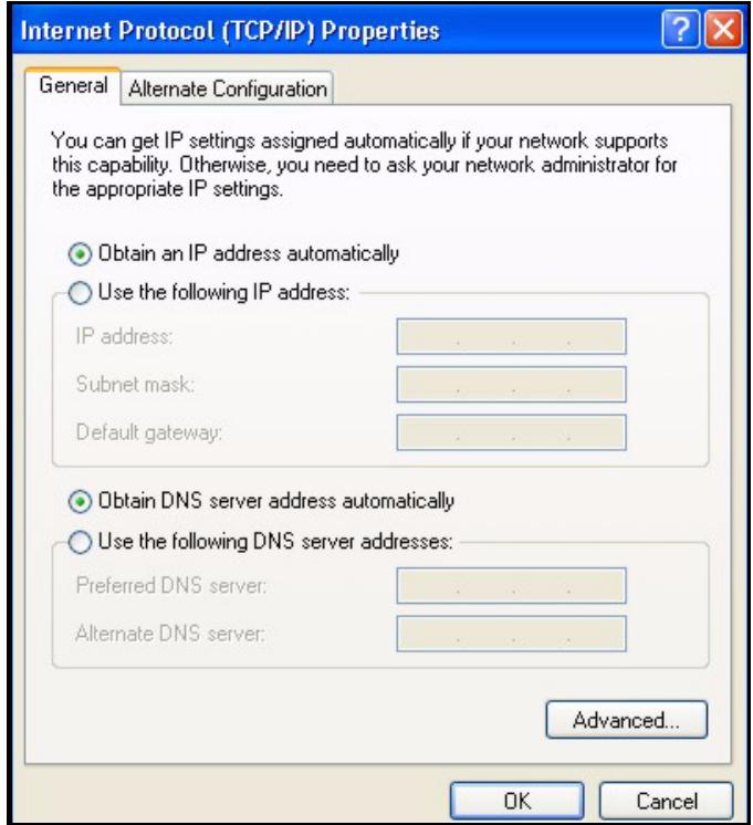
Figure 229 Windows XP: Internet Protocol (TCP/IP) Properties
6 If you do not know your gateway's IP address, remove any previously installed gateways in the IP Settings tab and click OK.
Do one or more of the following if you want to configure additional IP addresses:
- In the IP Settings tab, in IP addresses, click Add.
- In TCP/IP Address, type an IP address in IP address and a subnet mask in Subnet mask, and then click Add.
- Repeat the above two steps for each IP address you want to add.
- Configure additional default gateways in the IP Settings tab by clicking Add in Default gateways.
- In TCP/IP Gateway Address, type the IP address of the default gateway in Gateway. To manually configure a default metric (the number of transmission hops), clear the Automatic metric check box and type a metric in Metric.
- Click Add.
- Repeat the previous three steps for each default gateway you want to add.
- Click OK when finished.
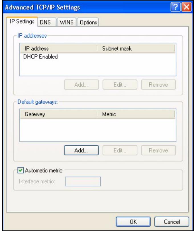
Figure 230 Windows XP: Advanced TCP/IP Properties
7 In the Internet Protocol TCP/IP Properties window (the General tab in Windows XP):
- Click Obtain DNS server address automatically if you do not know your DNS server IP address(es).
- If you know your DNS server IP address(es), click Use the following DNS server addresses, and type them in the Preferred DNS server and Alternate DNS server fields.
If you have previously configured DNS servers, click Advanced and then the DNS tab to order them.
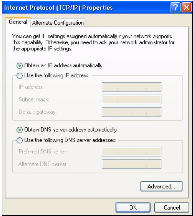
Figure 231 Windows XP: Internet Protocol (TCP/IP) Properties
8 Click OK to close the Internet Protocol (TCP/IP) Properties window.
9 Click Close (OK in Windows 2000/NT) to close the Local Area Connection Properties window.
10 Close the Network Connections window (Network and Dial-up Connections in Windows 2000/NT).
11 Turn on your ZyXEL Device and restart your computer (if prompted).
Verifying Settings
1 Click Start, All Programs, Accessories and then Command Prompt.
2 In the Command Prompt window, type "ipconfig" and then press [ENTER]. You can also open Network Connections, right-click a network connection, click Status and then click the Support tab.
Macintosh OS 8/9
1 Click the Apple menu, Control Panel and double-click TCP/IP to open the TCP/IP Control Panel.
Figure 232 Macintosh OS 8/9: Apple Menu
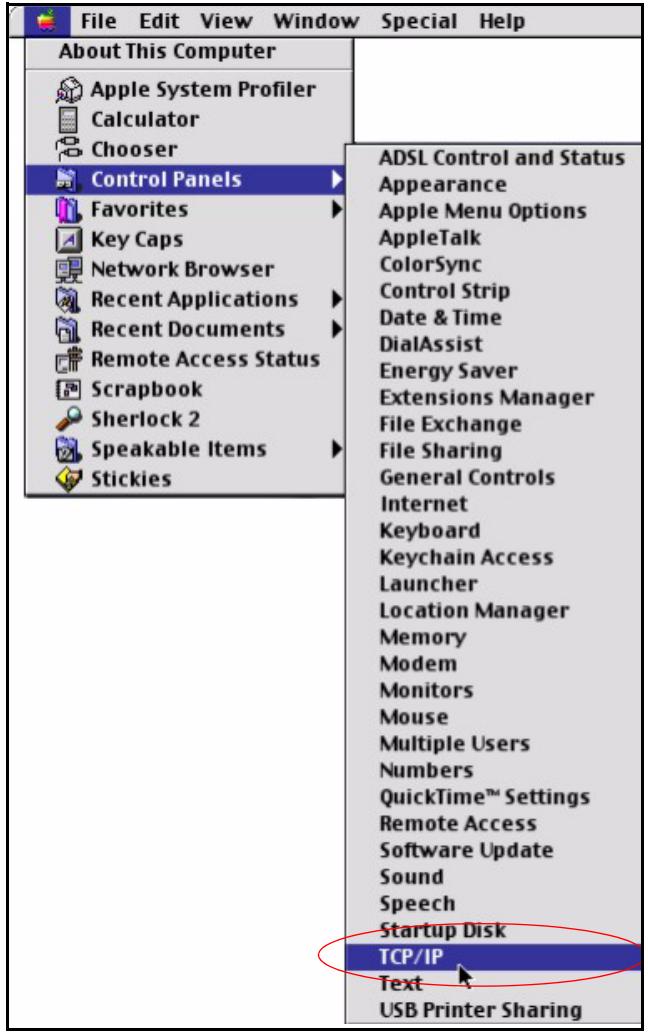
2 Select Ethernet built-in from the Connect via list.
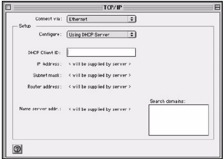
Figure 233 Macintosh OS 8/9: TCP/IP
3 For dynamically assigned settings, select Using DHCP Server from the Configure: list.
4 For statically assigned settings, do the following:
From the Configure box, select Manually.
- Type your IP address in the IP Address box.
- Type your subnet mask in the Subnet mask box.
- Type the IP address of your ZyXEL Device in the Router address box.
5 Close the TCP/IP Control Panel.
6 Click Save if prompted, to save changes to your configuration.
7 Turn on your ZyXEL Device and restart your computer (if prompted).
Verifying Settings
Check your TCP/IP properties in the TCP/IP Control Panel window.
Macintosh OS X
1 Click the Apple menu, and click System Preferences to open the System Preferences window.
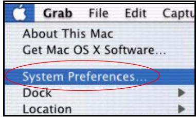
Figure 234 Macintosh OS X:Apple Menu
2 Click Network in the icon bar.
- Select Automatic from the Location list.
- Select Built-in Ethernet from the Show list.
- Click the TCP/IP tab.
3 For dynamically assigned settings, select Using DHCP from the Configure list.
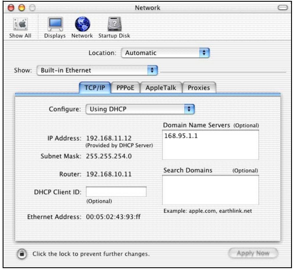
Figure 235 Macintosh OS X: Network
4 For statically assigned settings, do the following:
From the Configure box, select Manually.
- Type your IP address in the IP Address box.
- Type your subnet mask in the Subnet mask box.
- Type the IP address of your ZyXEL Device in the Router address box.
5 Click Apply Now and close the window.
6 Turn on your ZyXEL Device and restart your computer (if prompted).
Verifying Settings
Check your TCP/IP properties in the Network window.
Linux
This section shows you how to configure your computer's TCP/IP settings in Red Hat Linux 9.0. Procedure, screens and file location may vary depending on your Linux distribution and release version.

Make sure you are logged in as the root administrator.
Using the K Desktop Environment (KDE)
Follow the steps below to configure your computer IP address using the KDE.
1 Click the Red Hat button (located on the bottom left corner), select System Setting and click Network.
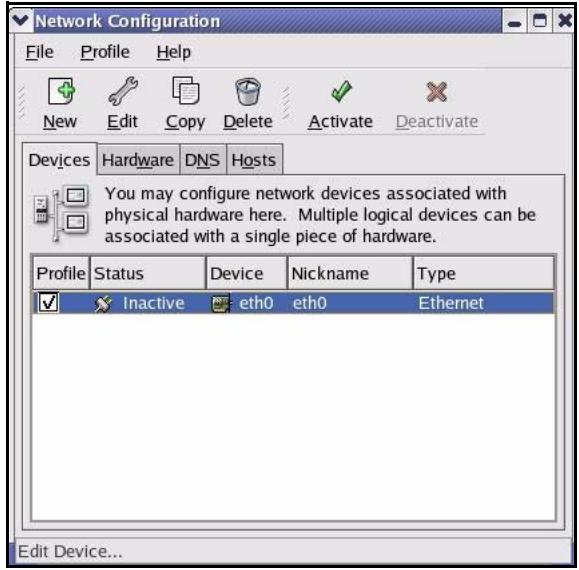
Figure 236 Red Hat 9.0: KDE: Network Configuration: Devices
2 Double-click on the profile of the network card you wish to configure. The Ethernet Device General screen displays as shown.
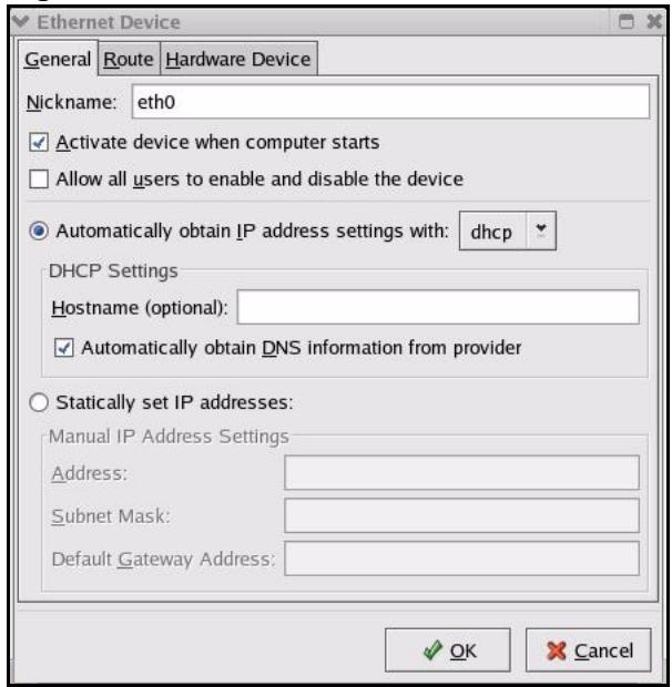
Figure 237 Red Hat 9.0: KDE: Ethernet Device: General
- If you have a dynamic IP address, click Automatically obtain IP address settings with and select dhcp from the drop down list.
- If you have a static IP address, click statically set IP Addresses and fill in the Address, Subnet mask, and Default Gateway Address fields.
3 Click OK to save the changes and close the Ethernet Device General screen.
4 If you know your DNS server IP address(es), click the DNS tab in the Network Configuration screen. Enter the DNS server information in the fields provided.
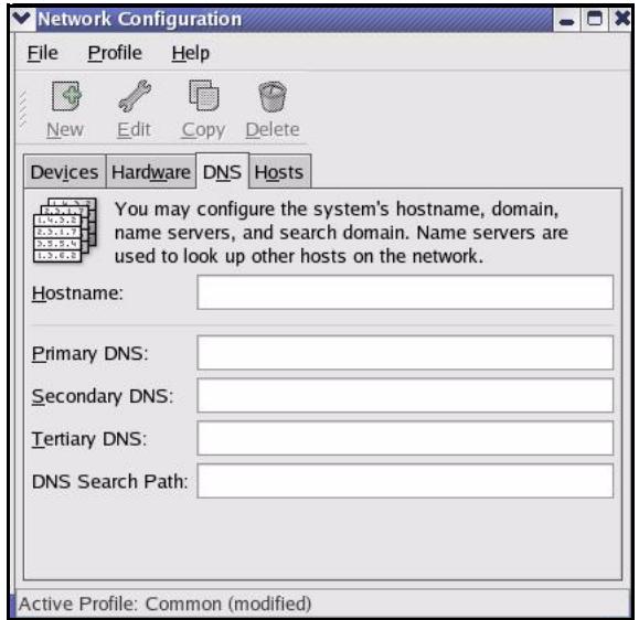
Figure 238 Red Hat 9.0: KDE: Network Configuration: DNS
5 Click the Devices tab.
6 Click the Activate button to apply the changes. The following screen displays. Click Yes to save the changes in all screens.
Figure 239 Red Hat 9.0: KDE: Network Configuration: Activate
7 After the network card restart process is complete, make sure the Status is Active in the Network Configuration screen.
Using Configuration Files
Follow the steps below to edit the network configuration files and set your computer IP address.
1 Assuming that you have only one network card on the computer, locate the ifconfig-eth0 configuration file (where eth0 is the name of the Ethernet card). Open the configuration file with any plain text editor.
- If you have a dynamic IP address, enter dhcp in the BOOTPROTO= field. The following figure shows an example.
Figure 240 Red Hat 9.0: Dynamic IP Address Setting in ifconfig-eth0
DEVICE=eth0
ONBOOT=yes
BOOTPROTO=dhcp
USERCTL=no
PEERDNS=yes
TYPE=Ethernet
- If you have a static IP address, enter static in the BOOTPROTO= field. Type IPADDR= followed by the IP address (in dotted decimal notation) and type NETMASK= followed by the subnet mask. The following example shows an example where the static IP address is 192.168.1.10 and the subnet mask is 255.255.255.0.
Figure 241 Red Hat 9.0: Static IP Address Setting in ifconfig-eth0
DEVICE eth0
ONBOOT yes
BOOTPROTO static
IPADDR = 192.168.1.10 NETMASK = 255.255.255.0 USERCTL no
PEERDNS yes
TYPE Ethernet
2 If you know your DNS server IP address(es), enter the DNS server information in the resolv.conf file in the /etc directory. The following figure shows an example where two DNS server IP addresses are specified.
Figure 242 Red Hat 9.0: DNS Settings in resolv.conf
nameserver 172.23.5.1
nameserver 172.23.5.2
3 After you edit and save the configuration files, you must restart the network card. Enter ./network restart in the /etc/rc.d/init.d directory. The following figure shows an example.
Figure 243 Red Hat 9.0: Restart Ethernet Card
[root@localhost init.d]# network restart Shutting down interface eth0: [OK] Shutting down loopback interface: [OK] Setting network parameters: [OK] Bringing up loopback interface: [OK] Bringing up interface eth0: [OK]
Verifying Settings
Enter ifconfig in a terminal screen to check your TCP/IP properties.
Figure 244 Red Hat 9.0: Checking TCP/IP Properties
[root@localhost]# ifconfig
eth0 Link encaps:Ethernet HWaddr 00:50:BA:72:5B:44 inlet addr:172.23.19.129 Bcast:172.23.19.255 Mask:255.255.255.0 UP BROADCAST RUNNING MULTICAST MTU:1500 Metric:1 RX packets:717 errors:0 dropped:0 overruns:0 frame:0 TX packets:13 errors:0 dropped:0 overruns:0 carrier:0 collisions:0 txqueuelen:100 RX bytes:730412 (713.2 Kb) TX bytes:1570 (1.5 Kb) Interrupt:10 Base address:0x1000
[root@localhost]#
IP Addresses and Subnetting
This appendix introduces IP addresses and subnet masks.
IP addresses identify individual devices on a network. Every networking device (including computers, servers, routers, printers, etc.) needs an IP address to communicate across the network. These networking devices are also known as hosts.
Subnet masks determine the maximum number of possible hosts on a network. You can also use subnet masks to divide one network into multiple sub-networks.
Introduction to IP Addresses
One part of the IP address is the network number, and the other part is the host ID. In the same way that houses on a street share a common street name, the hosts on a network share a common network number. Similarly, as each house has its own house number, each host on the network has its own unique identifying number - the host ID. Routers use the network number to send packets to the correct network, while the host ID determines to which host on the network the packets are delivered.
Structure
An IP address is made up of four parts, written in dotted decimal notation (for example, 192.168.1.1). Each of these four parts is known as an octet. An octet is an eight-digit binary number (for example 11000000, which is 192 in decimal notation).
Therefore, each octet has a possible range of 00000000 to 11111111 in binary, or 0 to 255 in decimal.
The following figure shows an example IP address in which the first three octets (192.168.1) are the network number, and the fourth octet (16) is the host ID.
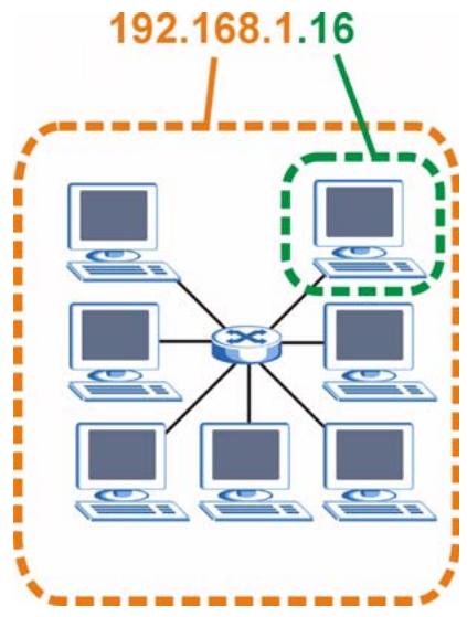
Figure 245 Network Number and Host ID
How much of the IP address is the network number and how much is the host ID varies according to the subnet mask.
Subnet Masks
A subnet mask is used to determine which bits are part of the network number, and which bits are part of the host ID (using a logical AND operation). The term "subset" is short for "subnetwork".
A subnet mask has 32 bits. If a bit in the subnet mask is a "1" then the corresponding bit in the IP address is part of the network number. If a bit in the subnet mask is "0" then the corresponding bit in the IP address is part of the host ID.
The following example shows a subnet mask identifying the network number (in bold text) and host ID of an IP address (192.168.1.2 in decimal).
Table 122 IP Address Network Number and Host ID Example
| 1ST OCTET: (192) | 2ND OCTET: (168) | 3RD OCTET: (1) | 4TH OCTET (2) | |
| IP Address (Binary) | 11000000 | 10101000 | 00000001 | 00000010 |
| Subnet Mask (Binary) | 11111111 | 11111111 | 11111111 | 00000000 |
| Network Number | 11000000 | 10101000 | 00000001 | |
| Host ID | 00000010 |
By convention, subnet masks always consist of a continuous sequence of ones beginning from the leftmost bit of the mask, followed by a continuous sequence of zeros, for a total number of 32 bits.
Subnet masks can be referred to by the size of the network number part (the bits with a "1" value). For example, an "8-bit mask" means that the first 8 bits of the mask are ones and the remaining 24 bits are zeroes.
Subnet masks are expressed in dotted decimal notation just like IP addresses. The following examples show the binary and decimal notation for 8-bit, 16-bit, 24-bit and 29-bit subnet masks.
Table 123 Subnet Masks
| BINARY | DECIMAL | ||||
| 1ST OCTET | 2ND OCTET | 3RD OCTET | 4TH OCTET | ||
| 8-bit mask | 11111111 | 00000000 | 00000000 | 00000000 | 255.0.0.0 |
| 16-bit mask | 11111111 | 11111111 | 00000000 | 00000000 | 255.255.0.0 |
| 24-bit mask | 11111111 | 11111111 | 11111111 | 00000000 | 255.255.255.0 |
| 29-bit mask | 11111111 | 11111111 | 11111111 | 11111000 | 255.255.255.248 |
Network Size
The size of the network number determines the maximum number of possible hosts you can have on your network. The larger the number of network number bits, the smaller the number of remaining host ID bits.
An IP address with host IDs of all zeros is the IP address of the network (192.168.1.0 with a 24-bit subnet mask, for example). An IP address with host IDs of all ones is the broadcast address for that network (192.168.1.255 with a 24-bit subnet mask, for example).
As these two IP addresses cannot be used for individual hosts, calculate the maximum number of possible hosts in a network as follows:
Table 124 Maximum Host Numbers
| SUBNET MASK | HOST ID SIZE | MAXIMUM NUMBER OF HOSTS | ||
| 8 bits | 255.0.0.0 | 24 bits | \( 2^{24} - 2 \) | 16777214 |
| 16 bits | 255.255.0.0 | 16 bits | \( 2^{16} - 2 \) | 65534 |
| 24 bits | 255.255.255.0 | 8 bits | \( 2^8 - 2 \) | 254 |
| 29 bits | 255.255.255.248 | 3 bits | \( 2^3 - 2 \) | 6 |
Notation
Since the mask is always a continuous number of ones beginning from the left, followed by a continuous number of zeros for the remainder of the 32 bit mask, you can simply specify the number of ones instead of writing the value of each octet. This is usually specified by writing a “/” followed by the number of bits in the mask after the address.
For example, 192.1.1.0 /25 is equivalent to saying 192.1.1.0 with subnet mask 255.255.255.128.
The following table shows some possible subnet masks using both notations.
Table 125 Alternative Subnet Mask Notation
| SUBNET MASK | ALTERNATIVE NOTATION | LAST OCTET (BINARY) | LAST OCTET (DECIMAL) |
| 255.255.255.0 | /24 | 0000 0000 | 0 |
| 255.255.255.128 | /25 | 1000 0000 | 128 |
| 255.255.255.192 | /26 | 1100 0000 | 192 |
| 255.255.255.224 | /27 | 1110 0000 | 224 |
| 255.255.255.240 | /28 | 1111 0000 | 240 |
| 255.255.255.248 | /29 | 1111 1000 | 248 |
| 255.255.255.252 | /30 | 1111 1100 | 252 |
Subnetting
You can use subnetting to divide one network into multiple sub-networks. In the following example a network administrator creates two sub-networks to isolate a group of servers from the rest of the company network for security reasons.
In this example, the company network address is 192.168.1.0. The first three octets of the address (192.168.1) are the network number, and the remaining octet is the host ID, allowing a maximum of 2^8 - 2 or 254 possible hosts.
The following figure shows the company network before submitting.
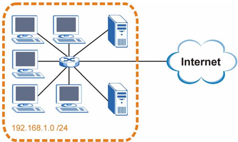
Figure 246 Subnetting Example: Before Subnetting
You can "borrow" one of the host ID bits to divide the network 192.168.1.0 into two separate sub-networks. The subnet mask is now 25 bits (255.255.255.128 or /25).
The "borrowed" host ID bit can have a value of either 0 or 1, allowing two subnets; 192.168.1.0 /25 and 192.168.1.128 /25.
The following figure shows the company network after subnetting. There are now two subnetworks, A and B.
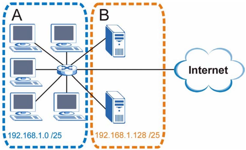
Figure 247 Subnetting Example: After Subnetting
In a 25-bit subnet the host ID has 7 bits, so each sub-network has a maximum of 2^7 - 2 or 126 possible hosts (a host ID of all zeroes is the subnet's address itself, all ones is the subnet's broadcast address).
192.168.1.0 with mask 255.255.255.128 is subnet A itself, and 192.168.1.127 with mask 255.255.255.128 is its broadcast address. Therefore, the lowest IP address that can be assigned to an actual host for subnet A is 192.168.1.1 and the highest is 192.168.1.126.
Similarly, the host ID range for subnet B is 192.168.1.129 to 192.168.1.254.
Example: Four Subnets
The previous example illustrated using a 25-bit subnet mask to divide a 24-bit address into two subnets. Similarly, to divide a 24-bit address into four subnets, you need to "borrow" two host ID bits to give four possible combinations (00, 01, 10 and 11). The subnet mask is 26 bits (11111111.11111111.11111111.1000000) or 255.255.255.192.
Each subnet contains 6 host ID bits, giving 2^6 - 2 or 62 hosts for each subnet (a host ID of all zeroes is the subnet itself, all ones is the subnet's broadcast address).
Table 126 Subnet 1
| IP/SUBNET MASK | NETWORK NUMBER | LAST OCTET BIT VALUE |
| IP Address (Decimal) | 192.168.1. | 0 |
| IP Address (Binary) | 11000000.10101000.00000001. | 00000000 |
| Subnet Mask (Binary) | 11111111.11111111.11111111. | 11000000 |
| Subnet Address: 192.168.1.0 | Lowest Host ID: 192.168.1.1 | |
| Broadcast Address: 192.168.1.63 | Highest Host ID: 192.168.1.62 | |
Table 127 Subnet 2
| IP/SUBNET MASK | NETWORK NUMBER | LAST OCTET BIT VALUE |
| IP Address | 192.168.1. | 64 |
| IP Address (Binary) | 11000000.10101000.00000001. | 01000000 |
| Subnet Mask (Binary) | 11111111.11111111.11111111. | 11000000 |
| Subnet Address: 192.168.1.64 | Lowest Host ID: 192.168.1.65 | |
| Broadcast Address: 192.168.1.127 | Highest Host ID: 192.168.1.126 | |
Table 128 Subnet 3
| IP/SUBNET MASK | NETWORK NUMBER | LAST OCTET BIT VALUE |
| IP Address | 192.168.1. | 128 |
| IP Address (Binary) | 11000000.10101000.00000001. | 10000000 |
| Subnet Mask (Binary) | 11111111.11111111.11111111. | 11000000 |
| Subnet Address: 192.168.1.128 | Lowest Host ID: 192.168.1.129 | |
| Broadcast Address: 192.168.1.191 | Highest Host ID: 192.168.1.190 | |
Table 129 Subnet 4
| IP/SUBNET MASK | NETWORK NUMBER | LAST OCTET BIT VALUE |
| IP Address | 192.168.1. | 192 |
| IP Address (Binary) | 11000000.10101000.00000001. | 11000000 |
| Subnet Mask (Binary) | 11111111.11111111.11111111. | 11000000 |
| Subnet Address: 192.168.1.192 | Lowest Host ID: 192.168.1.193 | |
| Broadcast Address: 192.168.1.255 | Highest Host ID: 192.168.1.254 | |
Example: Eight Subnets
Similarly, use a 27-bit mask to create eight subnets (000, 001, 010, 011, 100, 101, 110 and 111).
The following table shows IP address last octet values for each subnet.
Table 130 Eight Subnets
| SUBNET | SUBNET ADDRESS | FIRST ADDRESS | LAST ADDRESS | BROADCAST ADDRESS |
| 1 | 0 | 1 | 30 | 31 |
| 2 | 32 | 33 | 62 | 63 |
| 3 | 64 | 65 | 94 | 95 |
| 4 | 96 | 97 | 126 | 127 |
| 5 | 128 | 129 | 158 | 159 |
| 6 | 160 | 161 | 190 | 191 |
| 7 | 192 | 193 | 222 | 223 |
| 8 | 224 | 225 | 254 | 255 |
Subnet Planning
The following table is a summary for subnet planning on a network with a 24-bit network number.
Table 131 24-bit Network Number Subnet Planning
| NO. “BORROWED” HOST BITS | SUBNET MASK | NO. SUBNETS | NO. HOSTS PER SUBNET |
| 1 | 255.255.255.128 (/25) | 2 | 126 |
| 2 | 255.255.255.192 (/26) | 4 | 62 |
| 3 | 255.255.255.224 (/27) | 8 | 30 |
| 4 | 255.255.255.240 (/28) | 16 | 14 |
| 5 | 255.255.255.248 (/29) | 32 | 6 |
| 6 | 255.255.255.252 (/30) | 64 | 2 |
| 7 | 255.255.255.254 (/31) | 128 | 1 |
The following table is a summary for subnet planning on a network with a 16-bit network number.
Table 132 16-bit Network Number Subnet Planning
| NO. “BORROWED” HOST BITS | SUBNET MASK | NO. SUBNETS | NO. HOSTS PER SUBNET |
| 1 | 255.255.128.0 (/17) | 2 | 32766 |
| 2 | 255.255.192.0 (/18) | 4 | 16382 |
| 3 | 255.255.224.0 (/19) | 8 | 8190 |
| 4 | 255.255.240.0 (/20) | 16 | 4094 |
| 5 | 255.255.248.0 (/21) | 32 | 2046 |
| 6 | 255.255.252.0 (/22) | 64 | 1022 |
| 7 | 255.255.254.0 (/23) | 128 | 510 |
| 8 | 255.255.255.0 (/24) | 256 | 254 |
| 9 | 255.255.255.128 (/25) | 512 | 126 |
| 10 | 255.255.255.192 (/26) | 1024 | 62 |
| 11 | 255.255.255.224 (/27) | 2048 | 30 |
| 12 | 255.255.255.240 (/28) | 4096 | 14 |
| 13 | 255.255.255.248 (/29) | 8192 | 6 |
| 14 | 255.255.255.252 (/30) | 16384 | 2 |
| 15 | 255.255.255.254 (/31) | 32768 | 1 |
Configuring IP Addresses
Where you obtain your network number depends on your particular situation. If the ISP or your network administrator assigns you a block of registered IP addresses, follow their instructions in selecting the IP addresses and the subnet mask.
If the ISP did not explicitly give you an IP network number, then most likely you have a single user account and the ISP will assign you a dynamic IP address when the connection is established. If this is the case, it is recommended that you select a network number from 192.168.0.0 to 192.168.255.0. The Internet Assigned Number Authority (IANA) reserved this block of addresses specifically for private use; please do not use any other number unless you are told otherwise. You must also enable Network Address Translation (NAT) on the ZyXEL Device.
Once you have decided on the network number, pick an IP address for your ZyXEL Device that is easy to remember (for instance, 192.168.1.1) but make sure that no other device on your network is using that IP address.
The subnet mask specifies the network number portion of an IP address. Your ZyXEL Device will compute the subnet mask automatically based on the IP address that you entered. You don't need to change the subnet mask computed by the ZyXEL Device unless you are instructed to do otherwise.
Private IP Addresses
Every machine on the Internet must have a unique address. If your networks are isolated from the Internet (running only between two branch offices, for example) you can assign any IP addresses to the hosts without problems. However, the Internet Assigned Numbers Authority (IANA) has reserved the following three blocks of IP addresses specifically for private networks:
10.0.0.0 10.255.255.255
172.16.0.0 — 172.31.255.255
192.168.0.0—192.168.255.255
You can obtain your IP address from the IANA, from an ISP, or it can be assigned from a private network. If you belong to a small organization and your Internet access is through an ISP, the ISP can provide you with the Internet addresses for your local networks. On the other hand, if you are part of a much larger organization, you should consult your network administrator for the appropriate IP addresses.
Regardless of your particular situation, do not create an arbitrary IP address; always follow the guidelines above. For more information on address assignment, please refer to RFC 1597, Address Allocation for Private Internets and RFC 1466, Guidelines for Management of IP Address Space.
Common Services
The following table lists some commonly-used services and their associated protocols and port numbers. For a comprehensive list of port numbers, ICMP type/code numbers and services, visit the IANA (Internet Assigned Number Authority) web site.
- Name: This is a short, descriptive name for the service. You can use this one or create a different one, if you like.
- Protocol: This is the type of IP protocol used by the service. If this is TCP/UDP, then the service uses the same port number with TCP and UDP. If this is USER-DEFINED, the Port(s) is the IP protocol number, not the port number.
-
Port(s): This value depends on the Protocol. Please refer to RFC 1700 for further information about port numbers.
-
If the Protocol is TCP, UDP, or TCP/UDP, this is the IP port number.
-
If the Protocol is USER, this is the IP protocol number.
-
Description: This is a brief explanation of the applications that use this service or the situations in which this service is used.
Table 133 Commonly Used Services
| NAME | PROTOCOL | PORT(S) | DESCRIPTION |
| AH(IPSEC_TUNNEL) | User-Defined | 51 | The IPSEC AH (Authentication Header) tunneling protocol uses this service. |
| AIM/New-ICQ | TCP | 5190 | AOL's Internet Messenger service. It is also used as a listening port by ICQ. |
| AUTH | TCP | 113 | Authentication protocol used by some servers. |
| BGP | TCP | 179 | Border Gateway Protocol. |
| BOOTP_CLIENT | UDP | 68 | DHCP Client. |
| BOOTP_SERVER | UDP | 67 | DHCP Server. |
| CU-SEEME | TCP | 7648 | A popular videoconferencing solution from White Pines Software. |
| UDP | 24032 | ||
| DNS | TCP/UDP | 53 | Domain Name Server, a service that matches web names (e.g. www.zyxel.com) to IP numbers. |
| ESP(IPSEC_TUNNEL) | User-Defined | 50 | The IPSEC ESP (Encapsulation Security Protocol) tunneling protocol uses this service. |
| FINGER | TCP | 79 | Finger is a UNIX or Internet related command that can be used to find out if a user is logged on. |
| FTP | TCP | 20 | File Transfer Program, a program to enable fast transfer of files, including large files that may not be possible by e-mail. |
| TCP | 21 | ||
| H.323 | TCP | 1720 | NetMeeting uses this protocol. |
| HTTP | TCP | 80 | Hyper Text Transfer Protocol - a client/server protocol for the world wide web. |
| HTTPS | TCP | 443 | HTTPS is a secured http session often used in e-commerce. |
| ICMP | User-Defined | 1 | Internet Control Message Protocol is often used for diagnostic or routing purposes. |
| ICQ | UDP | 4000 | This is a popular Internet chat program. |
| IGMP (MULTICAST) | User-Defined | 2 | Internet Group Management Protocol is used when sending packets to a specific group of hosts. |
| IKE | UDP | 500 | The Internet Key Exchange algorithm is used for key distribution and management. |
| IRC | TCP/UDP | 6667 | This is another popular Internet chat program. |
| MSN Messenger | TCP | 1863 | Microsoft Networks' messenger service uses this protocol. |
| NEW-ICQ | TCP | 5190 | An Internet chat program. |
| NEWS | TCP | 144 | A protocol for news groups. |
| NFS | UDP | 2049 | Network File System - NFS is a client/server distributed file service that provides transparent file sharing for network environments. |
| NNTP | TCP | 119 | Network News Transport Protocol is the delivery mechanism for the USENET newsgroup service. |
| PING | User-Defined | 1 | Packet INternet Groper is a protocol that sends out ICMP echo requests to test whether or not a remote host is reachable. |
| POP3 | TCP | 110 | Post Office Protocol version 3 lets a client computer get e-mail from a POP3 server through a temporary connection (TCP/IP or other). |
| PPTP | TCP | 1723 | Point-to-Point Tunneling Protocol enables secure transfer of data over public networks. This is the control channel. |
| PPTP_TUNNEL (GRE) | User-Defined | 47 | PPTP (Point-to-Point Tunneling Protocol) enables secure transfer of data over public networks. This is the data channel. |
| RCMD | TCP | 512 | Remote Command Service. |
| REAL=AUDIO | TCP | 7070 | A streaming audio service that enables real time sound over the web. |
| REXEC | TCP | 514 | Remote Execution Daemon. |
| RLOGIN | TCP | 513 | Remote Login. |
| RTELNET | TCP | 107 | Remote Telnet. |
| RTSP | TCP/UDP | 554 | The Real Time Streaming (media control) Protocol (RTSP) is a remote control for multimedia on the Internet. |
| SFTP | TCP | 115 | Simple File Transfer Protocol. |
| SMTP | TCP | 25 | Simple Mail Transfer Protocol is the message-exchange standard for the Internet. SMTP enables you to move messages from one e-mail server to another. |
| SNMP | TCP/UDP | 161 | Simple Network Management Program. |
| SNMP-TRAPS | TCP/UDP | 162 | Traps for use with the SNMP (RFC:1215). |
| SQL-NET | TCP | 1521 | Structured Query Language is an interface to access data on many different types of database systems, including mainframes, midrange systems, UNIX systems and network servers. |
| SSH | TCP/UDP | 22 | Secure Shell Remote Login Program. |
| STRM WORKS | UDP | 1558 | Stream Works Protocol. |
| SYSLOG | UDP | 514 | Syslog allows you to send system logs to a UNIX server. |
| TACACS | UDP | 49 | Login Host Protocol used for (Terminal Access Controller Access Control System). |
| TELNET | TCP | 23 | Telnet is the login and terminal emulation protocol common on the Internet and in UNIX environments. It operates over TCP/IP networks. Its primary function is to allow users to log into remote host systems. |
| TFTP | UDP | 69 | Trivial File Transfer Protocol is an Internet file transfer protocol similar to FTP, but uses the UDP (User Datagram Protocol) rather than TCP (Transmission Control Protocol). |
| VDOLIVE | TCP | 7000 | Another videoconferencing solution. |
Wireless LANs
Wireless LAN Topologies
This section discusses ad-hoc and infrastructure wireless LAN topologies.
Ad-hoc Wireless LAN Configuration
The simplest WLAN configuration is an independent (Ad-hoc) WLAN that connects a set of computers with wireless adapters (A, B, C). Any time two or more wireless adapters are within range of each other, they can set up an independent network, which is commonly referred to as an ad-hoc network or Independent Basic Service Set (IBSS). The following diagram shows an example of notebook computers using wireless adapters to form an ad-hoc wireless LAN.
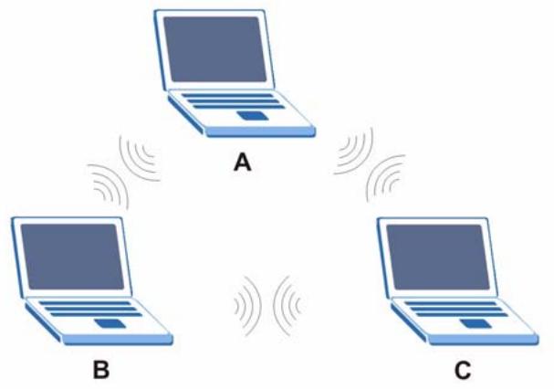
Figure 248 Peer-to-Peer Communication in an Ad-hoc Network
BSS
A Basic Service Set (BSS) exists when all communications between wireless clients or between a wireless client and a wired network client go through one access point (AP).
Intra-BSS traffic is traffic between wireless clients in the BSS. When Intra-BSS is enabled, wireless client A and B can access the wired network and communicate with each other. When Intra-BSS is disabled, wireless client A and B can still access the wired network but cannot communicate with each other.
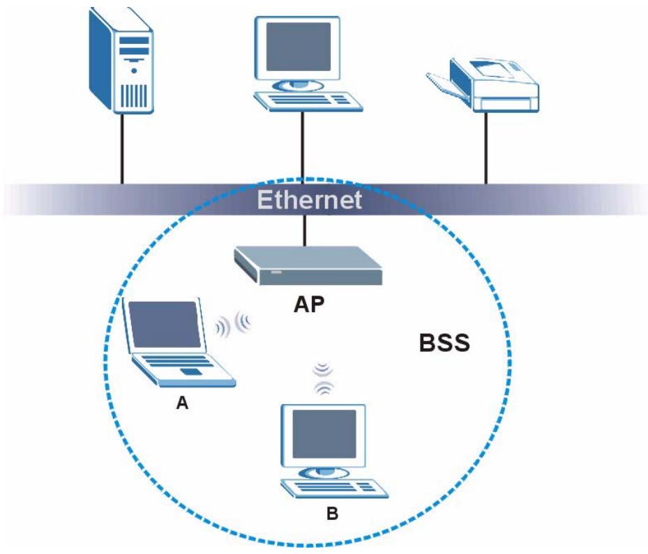
Figure 249 Basic Service Set
ESS
An Extended Service Set (ESS) consists of a series of overlapping BSSs, each containing an access point, with each access point connected together by a wired network. This wired connection between APs is called a Distribution System (DS).
This type of wireless LAN topology is called an Infrastructure WLAN. The Access Points not only provide communication with the wired network but also mediate wireless network traffic in the immediate neighborhood.
An ESSID (ESS IDentification) uniquely identifies each ESS. All access points and their associated wireless clients within the same ESS must have the same ESSID in order to communicate.
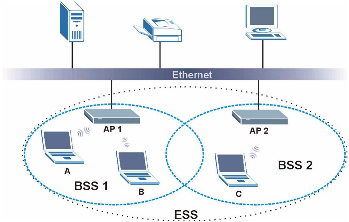
Figure 250 Infrastructure WLAN
Channel
A channel is the radio frequency(ies) used by wireless devices to transmit and receive data. Channels available depend on your geographical area. You may have a choice of channels (for your region) so you should use a channel different from an adjacent AP (access point) to reduce interference. Interference occurs when radio signals from different access points overlap causing interference and degrading performance.
Adjacent channels partially overlap however. To avoid interference due to overlap, your AP should be on a channel at least five channels away from a channel that an adjacent AP is using. For example, if your region has 11 channels and an adjacent AP is using channel 1, then you need to select a channel between 6 or 11.
RTS/CTS
A hidden node occurs when two stations are within range of the same access point, but are not within range of each other. The following figure illustrates a hidden node. Both stations (STA) are within range of the access point (AP) or wireless gateway, but out-of-range of each other, so they cannot "hear" each other, that is they do not know if the channel is currently being used. Therefore, they are considered hidden from each other.
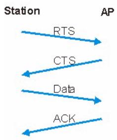
Figure 251 RTS/CTS
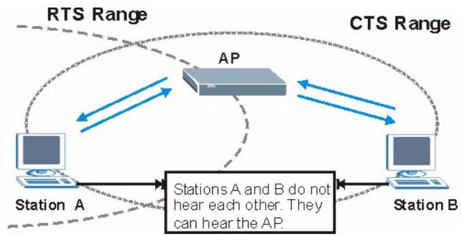
When station A sends data to the AP, it might not know that the station B is already using the channel. If these two stations send data at the same time, collisions may occur when both sets of data arrive at the AP at the same time, resulting in a loss of messages for both stations.
RTS/CTS is designed to prevent collisions due to hidden nodes. An RTS/CTS defines the biggest size data frame you can send before an RTS (Request To Send)/CTS (Clear to Send) handshake is invoked.
When a data frame exceeds the RTS/CTS value you set (between 0 to 2432 bytes), the station that wants to transmit this frame must first send an RTS (Request To Send) message to the AP for permission to send it. The AP then responds with a CTS (Clear to Send) message to all other stations within its range to notify them to defer their transmission. It also reserves and confirms with the requesting station the time frame for the requested transmission.
Stations can send frames smaller than the specified RTS/CTS directly to the AP without the RTS (Request To Send)/CTS (Clear to Send) handshake.
You should only configure RTS/CTS if the possibility of hidden nodes exists on your network and the "cost" of resending large frames is more than the extra network overhead involved in the RTS (Request To Send)/CTS (Clear to Send) handshake.
If the RTS/CTS value is greater than the Fragmentation Threshold value (see next), then the RTS (Request To Send)/CTS (Clear to Send) handshake will never occur as data frames will be fragmented before they reach RTS/CTS size.

Enabling the RTS Threshold causes redundant network overhead that could negatively affect the throughput performance instead of providing a remedy.
Fragmentation Threshold
A Fragmentation Threshold is the maximum data fragment size (between 256 and 2432 bytes) that can be sent in the wireless network before the AP will fragment the packet into smaller data frames.
A large Fragmentation Threshold is recommended for networks not prone to interference while you should set a smaller threshold for busy networks or networks that are prone to interference.
If the Fragmentation Threshold value is smaller than the RTS/CTS value (see previously) you set then the RTS (Request To Send)/CTS (Clear to Send) handshake will never occur as data frames will be fragmented before they reach RTS/CTS size.
Preamble Type
Preamble is used to signal that data is coming to the receiver. Short and long refer to the length of the synchronization field in a packet.
Short preamble increases performance as less time sending preamble means more time for sending data. All IEEE 802.11 compliant wireless adapters support long preamble, but not all support short preamble.
Use long preamble if you are unsure what preamble mode other wireless devices on the network support, and to provide more reliable communications in busy wireless networks.
Use short preamble if you are sure all wireless devices on the network support it, and to provide more efficient communications.
Use the dynamic setting to automatically use short preamble when all wireless devices on the network support it, otherwise the ZyXEL Device uses long preamble.

The wireless devices MUST use the same preamble mode in order to communicate.
IEEE 802.11g Wireless LAN
IEEE 802.11g is fully compatible with the IEEE 802.11b standard. This means an IEEE 802.11b adapter can interface directly with an IEEE 802.11g access point (and vice versa) at 11 Mbps or lower depending on range. IEEE 802.11g has several intermediate rate steps between the maximum and minimum data rates. The IEEE 802.11g data rate and modulation are as follows:
Table 134 IEEE 802.11g
| DATA RATE (MBPS) | MODULATION |
| 1 | DBPSK (Differential Binary Phase Shift Keyed) |
| 2 | DQPSK (Differential Quadrature Phase Shift Keying) |
| 5.5 / 11 | CCK (Complementary Code Keying) |
| 6/9/12/18/24/36/48/54 | OFDM (Orthogonal Frequency Division Multiplexing) |
Wireless Security Overview
Wireless security is vital to your network to protect wireless communication between wireless clients, access points and the wired network.
Wireless security methods available on the ZyXEL Device are data encryption, wireless client authentication, restricting access by device MAC address and hiding the ZyXEL Device identity.
The following figure shows the relative effectiveness of these wireless security methods available on your ZyXEL Device.
Table 135 Wireless Security Levels
| SECURITY LEVEL | SECURITY TYPE |
| Least Secure Most Secure | Unique SSID (Default) |
| Unique SSID with Hide SSID Enabled | |
| MAC Address Filtering | |
| WEP Encryption | |
| IEEE802.1x EAP with RADIUS Server Authentication | |
| Wi-Fi Protected Access (WPA) | |
| WPA2 |

You must enable the same wireless security settings on the ZyXEL Device and on all wireless clients that you want to associate with it.
IEEE 802.1x
In June 2001, the IEEE 802.1x standard was designed to extend the features of IEEE 802.11 to support extended authentication as well as providing additional accounting and control features. It is supported by Windows XP and a number of network devices. Some advantages of IEEE 802.1x are:
- User based identification that allows for roaming.
- Support for RADIUS (Remote Authentication Dial In User Service, RFC 2138, 2139) for centralized user profile and accounting management on a network RADIUS server.
- Support for EAP (Extensible Authentication Protocol, RFC 2486) that allows additional authentication methods to be deployed with no changes to the access point or the wireless clients.
RADIUS
RADIUS is based on a client-server model that supports authentication, authorization and accounting. The access point is the client and the server is the RADIUS server. The RADIUS server handles the following tasks:
Authentication
Determines the identity of the users.
- Authorization
Determines the network services available to authenticated users once they are connected to the network.
- Accounting
Keeps track of the client's network activity.
RADIUS is a simple package exchange in which your AP acts as a message relay between the wireless client and the network RADIUS server.
Types of RADIUS Messages
The following types of RADIUS messages are exchanged between the access point and the RADIUS server for user authentication:
- Access-Request
Sent by an access point requesting authentication.
- Access-Reject
Sent by a RADIUS server rejecting access.
- Access-Accept
Sent by a RADIUS server allowing access.
- Access-Challenge
Sent by a RADIUS server requesting more information in order to allow access. The access point sends a proper response from the user and then sends another Access-Request message.
The following types of RADIUS messages are exchanged between the access point and the RADIUS server for user accounting:
- Accounting-Request
Sent by the access point requesting accounting.
- Accounting-Response
Sent by the RADIUS server to indicate that it has started or stopped accounting.
In order to ensure network security, the access point and the RADIUS server use a shared secret key, which is a password, they both know. The key is not sent over the network. In addition to the shared key, password information exchanged is also encrypted to protect the network from unauthorized access.
Types of EAP Authentication
This section discusses some popular authentication types: EAP-MD5, EAP-TLS, EAP-TTLS, PEAP and LEAP. Your wireless LAN device may not support all authentication types.
EAP (Extensible Authentication Protocol) is an authentication protocol that runs on top of the IEEE 802.1x transport mechanism in order to support multiple types of user authentication. By using EAP to interact with an EAP-compatible RADIUS server, an access point helps a wireless station and a RADIUS server perform authentication.
The type of authentication you use depends on the RADIUS server and an intermediary AP(s) that supports IEEE 802.1x.
For EAP-TLS authentication type, you must first have a wired connection to the network and obtain the certificate(s) from a certificate authority (CA). A certificate (also called digital IDs) can be used to authenticate users and a CA issues certificates and guarantees the identity of each certificate owner.
EAP-MD5 (Message-Digest Algorithm 5)
MD5 authentication is the simplest one-way authentication method. The authentication server sends a challenge to the wireless client. The wireless client 'proves' that it knows the password by encrypting the password with the challenge and sends back the information. Password is not sent in plain text.
However, MD5 authentication has some weaknesses. Since the authentication server needs to get the plaintext passwords, the passwords must be stored. Thus someone other than the authentication server may access the password file. In addition, it is possible to impersonate an authentication server as MD5 authentication method does not perform mutual authentication. Finally, MD5 authentication method does not support data encryption with dynamic session key. You must configure WEP encryption keys for data encryption.
EAP-TLS (Transport Layer Security)
With EAP-TLS, digital certifications are needed by both the server and the wireless clients for mutual authentication. The server presents a certificate to the client. After validating the identity of the server, the client sends a different certificate to the server. The exchange of certificates is done in the open before a secured tunnel is created. This makes user identity vulnerable to passive attacks. A digital certificate is an electronic ID card that authenticates the sender's identity. However, to implement EAP-TLS, you need a Certificate Authority (CA) to handle certificates, which imposes a management overhead.
EAP-TTLS (Tunnel Transport Layer Service)
EAP-TTLS is an extension of the EAP-TLS authentication that uses certificates for only the server-side authentications to establish a secure connection. Client authentication is then done by sending username and password through the secure connection, thus client identity is protected. For client authentication, EAP-TTLS supports EAP methods and legacy authentication methods such as PAP, CHAP, MS-CHAP and MS-CHAP v2.
PEAP (Protected EAP)
Like EAP-TTLS, server-side certificate authentication is used to establish a secure connection, then use simple username and password methods through the secured connection to authenticate the clients, thus hiding client identity. However, PEAP only supports EAP methods, such as EAP-MD5, EAP-MSCHAPv2 and EAP-GTC (EAP-Generic Token Card), for client authentication. EAP-GTC is implemented only by Cisco.
LEAP
LEAP (Lightweight Extensible Authentication Protocol) is a Cisco implementation of IEEE 802.1x.
Dynamic WEP Key Exchange
The AP maps a unique key that is generated with the RADIUS server. This key expires when the wireless connection times out, disconnects or reauthentication times out. A new WEP key is generated each time reauthentication is performed.
If this feature is enabled, it is not necessary to configure a default encryption key in the wireless security configuration screen. You may still configure and store keys, but they will not be used while dynamic WEP is enabled.

EAP-MD5 cannot be used with Dynamic WEP Key Exchange
For added security, certificate-based authentications (EAP-TLS, EAP-TTLS and PEAP) use dynamic keys for data encryption. They are often deployed in corporate environments, but for public deployment, a simple user name and password pair is more practical. The following table is a comparison of the features of authentication types.
Table 136 Comparison of EAP Authentication Types
| EAP-MD5 | EAP-TLS | EAP-TTLS | PEAP | LEAP | |
| Mutual Authentication | No | Yes | Yes | Yes | Yes |
| Certificate – Client | No | Yes | Optional | Optional | No |
| Certificate – Server | No | Yes | Yes | Yes | No |
| Dynamic Key Exchange | No | Yes | Yes | Yes | Yes |
| Credential Integrity | None | Strong | Strong | Strong | Moderate |
| Deployment Difficulty | Easy | Hard | Moderate | Moderate | Moderate |
| Client Identity Protection | No | No | Yes | Yes | No |
WPA and WPA2
Wi-Fi Protected Access (WPA) is a subset of the IEEE 802.11i standard. WPA2 (IEEE 802.11i) is a wireless security standard that defines stronger encryption, authentication and key management than WPA.
Key differences between WPA or WPA2 and WEP are improved data encryption and user authentication.
If both an AP and the wireless clients support WPA2 and you have an external RADIUS server, use WPA2 for stronger data encryption. If you don't have an external RADIUS server, you should use WPA2-PSK (WPA2-Pre-Shared Key) that only requires a single (identical) password entered into each access point, wireless gateway and wireless client. As long as the passwords match, a wireless client will be granted access to a WLAN.
If the AP or the wireless clients do not support WPA2, just use WPA or WPA-PSK depending on whether you have an external RADIUS server or not.
Select WEP only when the AP and/or wireless clients do not support WPA or WPA2. WEP is less secure than WPA or WPA2.
Encryption
Both WPA and WPA2 improve data encryption by using Temporal Key Integrity Protocol (TKIP), Message Integrity Check (MIC) and IEEE 802.1x. WPA and WPA2 use Advanced Encryption Standard (AES) in the Counter mode with Cipher block chaining Message authentication code Protocol (CCMP) to offer stronger encryption than TKIP.
TKIP uses 128-bit keys that are dynamically generated and distributed by the authentication server. AES (Advanced Encryption Standard) is a block cipher that uses a 256-bit mathematical algorithm called Rijndael. They both include a per-packet key mixing function, a Message Integrity Check (MIC) named Michael, an extended initialization vector (IV) with sequencing rules, and a re-keying mechanism.
WPA and WPA2 regularly change and rotate the encryption keys so that the same encryption key is never used twice.
The RADIUS server distributes a Pairwise Master Key (PMK) key to the AP that then sets up a key hierarchy and management system, using the PMK to dynamically generate unique data encryption keys to encrypt every data packet that is wirelessly communicated between the AP and the wireless clients. This all happens in the background automatically.
The Message Integrity Check (MIC) is designed to prevent an attacker from capturing data packets, altering them and resending them. The MIC provides a strong mathematical function in which the receiver and the transmitter each compute and then compare the MIC. If they do not match, it is assumed that the data has been tampered with and the packet is dropped.
By generating unique data encryption keys for every data packet and by creating an integrity checking mechanism (MIC), with TKIP and AES it is more difficult to decrypt data on a Wi-Fi network than WEP and difficult for an intruder to break into the network.
The encryption mechanisms used for WPA(2) and WPA(2)-PSK are the same. The only difference between the two is that WPA(2)-PSK uses a simple common password, instead of user-specific credentials. The common-password approach makes WPA(2)-PSK susceptible to brute-force password-guessing attacks but it's still an improvement over WEP as it employs a consistent, single, alphanumeric password to derive a PMK which is used to generate unique temporal encryption keys. This prevent all wireless devices sharing the same encryption keys. (a weakness of WEP)
User Authentication
WPA and WPA2 apply IEEE 802.1x and Extensible Authentication Protocol (EAP) to authenticate wireless clients using an external RADIUS database. WPA2 reduces the number of key exchange messages from six to four (CCMP 4-way handshake) and shortens the time required to connect to a network. Other WPA2 authentication features that are different from WPA include key caching and pre-authentication. These two features are optional and may not be supported in all wireless devices.
Key caching allows a wireless client to store the PMK it derived through a successful authentication with an AP. The wireless client uses the PMK when it tries to connect to the same AP and does not need to go with the authentication process again.
Pre-authentication enables fast roaming by allowing the wireless client (already connecting to an AP) to perform IEEE 802.1x authentication with another AP before connecting to it.
Wireless Client WPA Suppliers
A wireless client supplicant is the software that runs on an operating system instructing the wireless client how to use WPA. At the time of writing, the most widely available supplicant is the WPA patch for Windows XP, Funk Software's Odyssey client.
The Windows XP patch is a free download that adds WPA capability to Windows XP's built-in "Zero Configuration" wireless client. However, you must run Windows XP to use it.
WPA(2) with RADIUS Application Example
To set up WPA(2), you need the IP address of the RADIUS server, its port number (default is 1812), and the RADIUS shared secret. A WPA(2) application example with an external RADIUS server looks as follows. "A" is the RADIUS server. "DS" is the distribution system.
1 The AP passes the wireless client's authentication request to the RADIUS server.
2 The RADIUS server then checks the user's identification against its database and grants or denies network access accordingly.
3 A 256-bit Pairwise Master Key (PMK) is derived from the authentication process by the RADIUS server and the client.
4 The RADIUS server distributes the PMK to the AP. The AP then sets up a key hierarchy and management system, using the PMK to dynamically generate unique data encryption keys. The keys are used to encrypt every data packet that is wirelessly communicated between the AP and the wireless clients.
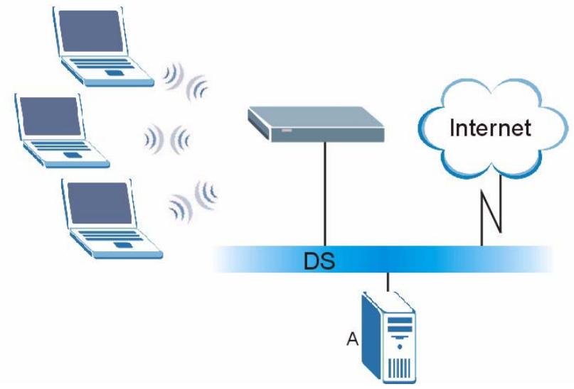
Figure 252 WPA(2) with RADIUS Application Example
WPA(2)-PSK Application Example
A WPA(2)-PSK application looks as follows.
1 First enter identical passwords into the AP and all wireless clients. The Pre-Shared Key (PSK) must consist of between 8 and 63 ASCII characters or 64 hexadecimal characters (including spaces and symbols).
2 The AP checks each wireless client's password and allows it to join the network only if the password matches.
3 The AP and wireless clients generate a common PMK (Pairwise Master Key). The key itself is not sent over the network, but is derived from the PSK and the SSID.
4 The AP and wireless clients use the TKIP or AES encryption process, the PMK and information exchanged in a handshake to create temporal encryption keys. They use these keys to encrypt data exchanged between them.
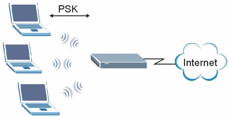
Figure 253 WPA(2)-PSK Authentication
Security Parameters Summary
Refer to this table to see what other security parameters you should configure for each authentication method or key management protocol type. MAC address filters are not dependent on how you configure these security features.
Table 137 Wireless Security Relational Matrix
| AUTHENTICATION METHOD/ KEYMANAGEMENT PROTOCOL | ENCRYPTION METHOD | ENTERMANUAL KEY | IEEE 802.1X |
| Open | None | No | Disable |
| Enable without Dynamic WEP Key | |||
| Open | WEP | No | Enable with Dynamic WEP Key |
| Yes | Enable without Dynamic WEP Key | ||
| Yes | Disable | ||
| Shared | WEP | No | Enable with Dynamic WEP Key |
| Yes | Enable without Dynamic WEP Key | ||
| Yes | Disable | ||
| WPA | TKIP/AES | No | Enable |
| WPA-PSK | TKIP/AES | Yes | Disable |
| WPA2 | TKIP/AES | No | Enable |
| WPA2-PSK | TKIP/AES | Yes | Disable |
Antenna Overview
An antenna couples RF signals onto air. A transmitter within a wireless device sends an RF signal to the antenna, which propagates the signal through the air. The antenna also operates in reverse by capturing RF signals from the air.
Positioning the antennas properly increases the range and coverage area of a wireless LAN.
Antenna Characteristics
Frequency
An antenna in the frequency of 2.4GHz (IEEE 802.11b and IEEE 802.11g) or 5GHz (IEEE 802.11a) is needed to communicate efficiently in a wireless LAN
Radiation Pattern
A radiation pattern is a diagram that allows you to visualize the shape of the antenna's coverage area.
Antenna Gain
Antenna gain, measured in dB (decibel), is the increase in coverage within the RF beam width. Higher antenna gain improves the range of the signal for better communications.
For an indoor site, each 1 dB increase in antenna gain results in a range increase of approximately 2.5% . For an unobstructed outdoor site, each 1dB increase in gain results in a range increase of approximately 5% . Actual results may vary depending on the network environment.
Antenna gain is sometimes specified in dBi, which is how much the antenna increases the signal power compared to using an isotropic antenna. An isotropic antenna is a theoretical perfect antenna that sends out radio signals equally well in all directions. dBi represents the true gain that the antenna provides.
Types of Antennas for WLAN
There are two types of antennas used for wireless LAN applications.
- Omni-directional antennas send the RF signal out in all directions on a horizontal plane. The coverage area is torus-shaped (like a donut) which makes these antennas ideal for a room environment. With a wide coverage area, it is possible to make circular overlapping coverage areas with multiple access points.
- Directional antennas concentrate the RF signal in a beam, like a flashlight does with the light from its bulb. The angle of the beam determines the width of the coverage pattern. Angles typically range from 20 degrees (very directional) to 120 degrees (less directional). Directional antennas are ideal for hallways and outdoor point-to-point applications.
Positioning Antennas
In general, antennas should be mounted as high as practically possible and free of obstructions. In point-to-point application, position both antennas at the same height and in a direct line of sight to each other to attain the best performance.
For omni-directional antennas mounted on a table, desk, and so on, point the antenna up. For omni-directional antennas mounted on a wall or ceiling, point the antenna down. For a single AP application, place omni-directional antennas as close to the center of the coverage area as possible.
For directional antennas, point the antenna in the direction of the desired coverage area.
Importing Certificates
This appendix shows importing certificates examples using Internet Explorer 5.
Import ZyXEL Device Certificates into Netscape Navigator
In Netscape Navigator, you can permanently trust the ZyXEL Device's server certificate by importing it into your operating system as a trusted certification authority.
Select Accept This Certificate Permanently in the following screen to do this.
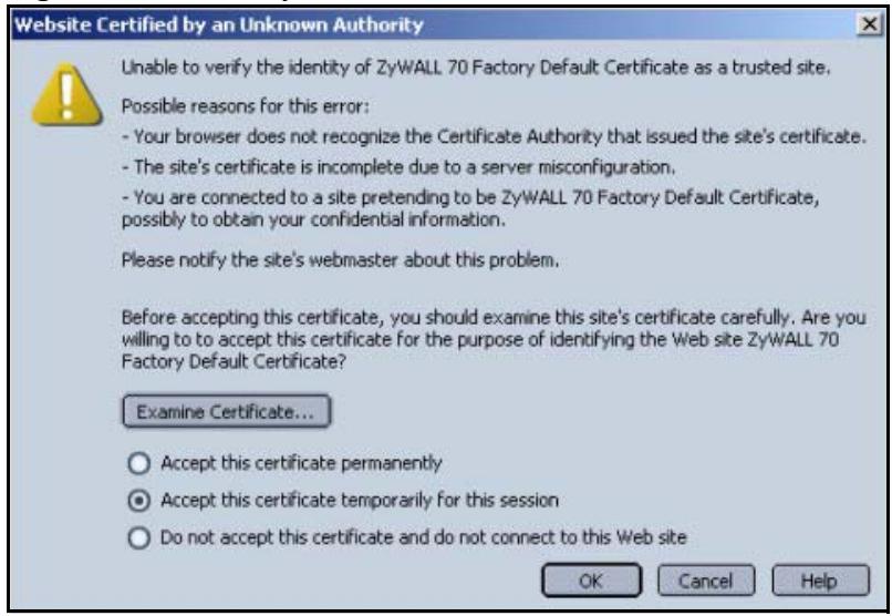
Figure 254 Security Certificate
Importing the ZyXEL Device's Certificate into Internet Explorer
For Internet Explorer to trust a self-signed certificate from the ZyXEL Device, simply import the self-signed certificate into your operating system as a trusted certification authority.
To have Internet Explorer trust a ZyXEL Device certificate issued by a certificate authority, import the certificate authority's certificate into your operating system as a trusted certification authority.
The following example procedure shows how to import the ZyXEL Device's (self-signed) server certificate into your operating system as a trusted certification authority.
1 In Internet Explorer, double click the lock shown in the following screen.
Figure 255 Login Screen
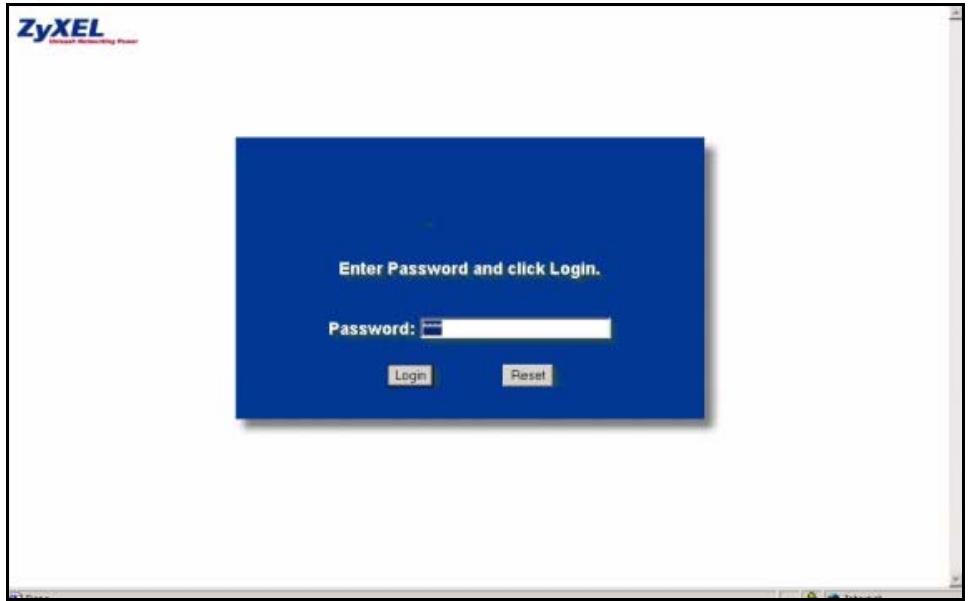
2 Click Install Certificate to open the Install Certificate wizard.
Figure 256 Certificate General Information before Import
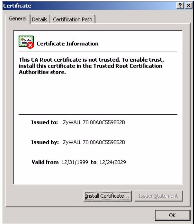
3 Click Next to begin the Install Certificate wizard.
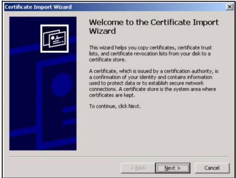
Figure 257 Certificate Import Wizard 1
4 Select where you would like to store the certificate and then click Next.
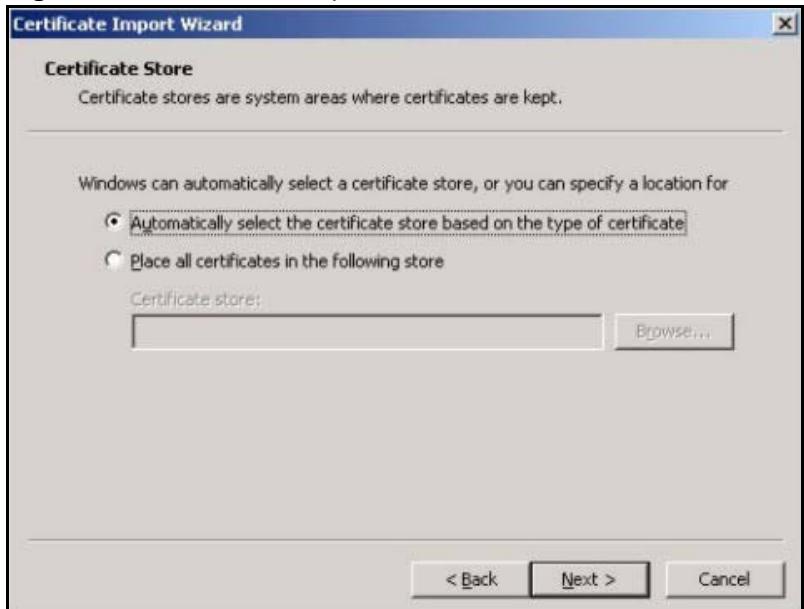
Figure 258 Certificate Import Wizard 2
5 Click Finish to complete the Import Certificate wizard.
Figure 259 Certificate Import Wizard 3
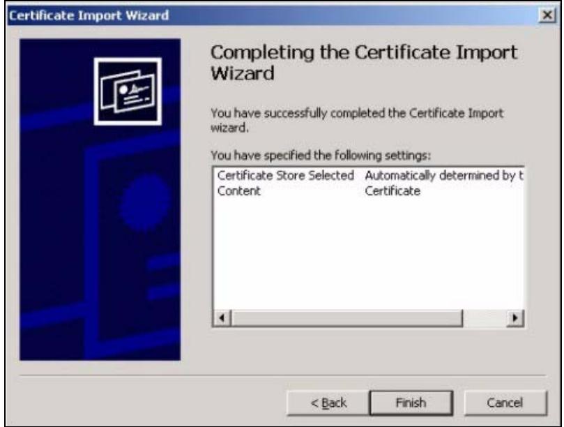
6 Click Yes to add the ZyXEL Device certificate to the root store.
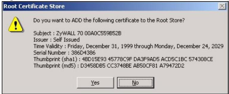
Figure 260 Root Certificate Store
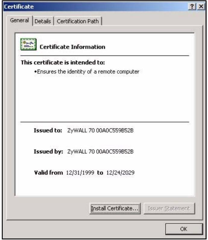
Figure 261 Certificate General Information after Import
Enrolling and Importing SSL Client Certificates
The SSL client needs a certificate if Authenticate Client Certificates is selected on the ZyXEL Device.
You must have imported at least one trusted CA to the ZyXEL Device in order for the Authenticate Client Certificates to be active (see the Certificates chapter for details).
Apply for a certificate from a Certification Authority (CA) that is trusted by the ZyXEL Device (see the ZyXEL Device's Trusted CA web configurator screen).
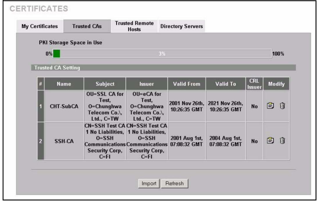
Figure 262 ZyXEL Device Trusted CA Screen
The CA sends you a package containing the CA's trusted certificate(s), your personal certificate(s) and a password to install the personal certificate(s).
Installing the CA's Certificate
1 Double click the CA's trusted certificate to produce a screen similar to the one shown next.
Figure 263 CA Certificate Example
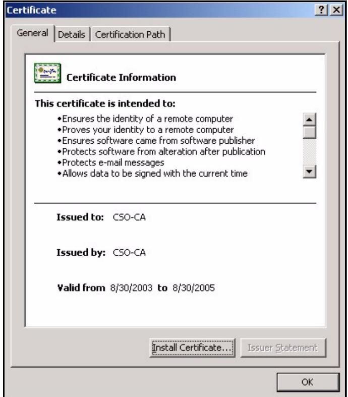
2 Click Install Certificate and follow the wizard as shown earlier in this appendix.
Installing Your Personal Certificate(s)
You need a password in advance. The CA may issue the password or you may have to specify it during the enrollment. Double-click the personal certificate given to you by the CA to produce a screen similar to the one shown next
1 Click Next to begin the wizard.
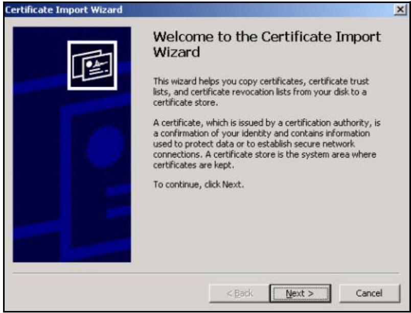
Figure 264 Personal Certificate Import Wizard 1
2 The file name and path of the certificate you double-clicked should automatically appear in the File name text box. Click Browse if you wish to import a different certificate.
Figure 265 Personal Certificate Import Wizard 2
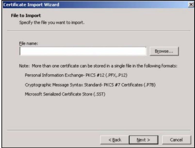
3 Enter the password given to you by the CA.
Figure 266 Personal Certificate Import Wizard 3
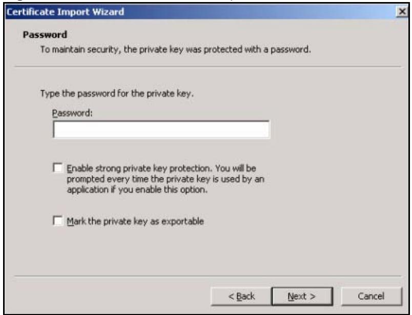
4 Have the wizard determine where the certificate should be saved on your computer or select Place all certificates in the following store and choose a different location.
Figure 267 Personal Certificate Import Wizard 4
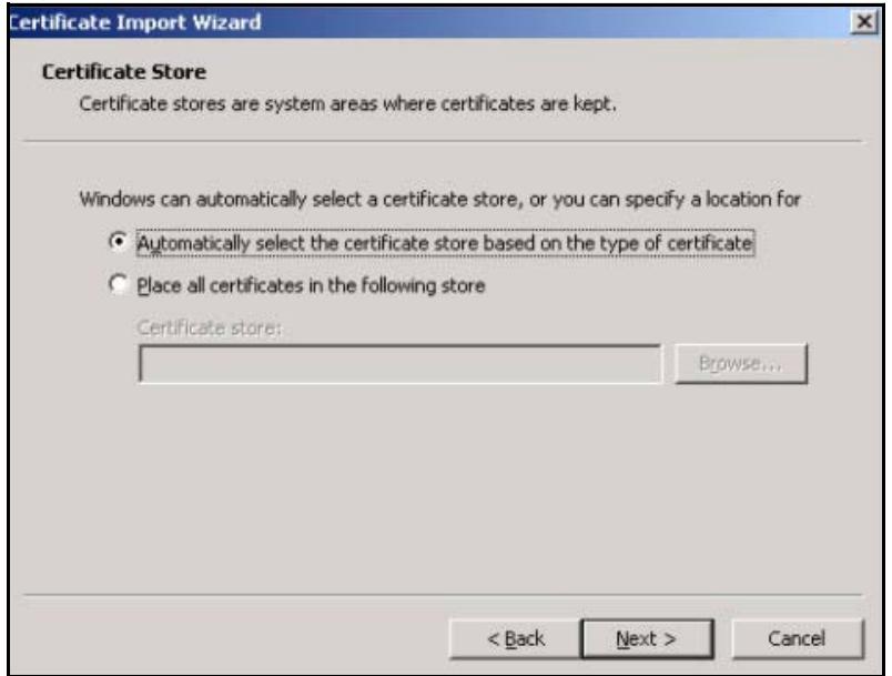
5 Click Finish to complete the wizard and begin the import process.
Figure 268 Personal Certificate Import Wizard 5
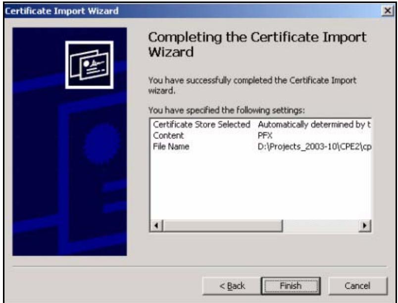
6 You should see the following screen when the certificate is correctly installed on your computer.
Figure 269 Personal Certificate Import Wizard 6
Using a Certificate When Accessing the ZyXEL Device Example
Use the following procedure to access the ZyXEL Device via HTTPS.
1 Enter 'https://ZyXEL Device IP Address/ in your browser's web address field.
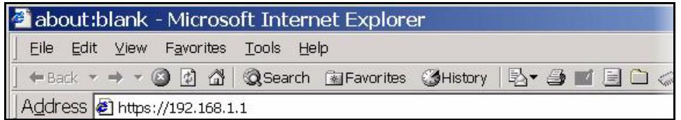
Figure 270 Access the ZyXEL Device Via HTTPS
2 When Authenticate Client Certificates is selected on the ZyXEL Device, the following screen asks you to select a personal certificate to send to the ZyXEL Device. This screen displays even if you only have a single certificate as in the example.
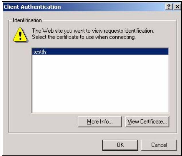
Figure 271 SSL Client Authentication
3 You next see the ZyXEL Device login screen.
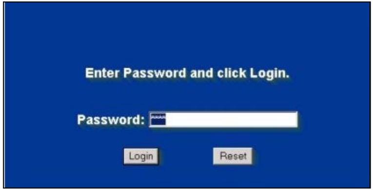
Figure 272 ZyXEL Device Secure Login Screen
Legal Information
Copyright
Copyright © 2008 by ZyXEL Communications Corporation.
The contents of this publication may not be reproduced in any part or as a whole, transcribed, stored in a retrieval system, translated into any language, or transmitted in any form or by any means, electronic, mechanical, magnetic, optical, chemical, photocopying, manual, or otherwise, without the prior written permission of ZyXEL Communications Corporation.
Published by ZyXEL Communications Corporation. All rights reserved.
Disclaimer
ZyXEL does not assume any liability arising out of the application or use of any products, or software described herein. Neither does it convey any license under its patent rights nor the patent rights of others. ZyXEL further reserves the right to make changes in any products described herein without notice. This publication is subject to change without notice.
Your use of the ZyXEL Device is subject to the terms and conditions of any related service providers.
Trademarks
ZyNOS (ZyXEL Network Operating System) is a registered trademark of ZyXEL Communications, Inc. Other trademarks mentioned in this publication are used for identification purposes only and may be properties of their respective owners.
Certifications
Federal Communications Commission (FCC) Interference Statement
The device complies with Part 15 of FCC rules. Operation is subject to the following two conditions:
- This device may not cause harmful interference.
- This device must accept any interference received, including interference that may cause undesired operations.
This device has been tested and found to comply with the limits for a Class B digital device pursuant to Part 15 of the FCC Rules. These limits are designed to provide reasonable protection against harmful interference in a residential installation. This device generates, uses, and can radiate radio frequency energy, and if not installed and used in accordance with the instructions, may cause harmful interference to radio communications. However, there is no guarantee that interference will not occur in a particular installation.
If this device does cause harmful interference to radio/television reception, which can be determined by turning the device off and on, the user is encouraged to try to correct the interference by one or more of the following measures:
1 Reorient or relocate the receiving antenna.
2 Increase the separation between the equipment and the receiver.
3 Connect the equipment into an outlet on a circuit different from that to which the receiver is connected.
4 Consult the dealer or an experienced radio/TV technician for help.
FCC Radiation Exposure Statement
- This transmitter must not be co-located or operating in conjunction with any other antenna or transmitter.
- IEEE 802.11b or 802.11g operation of this product in the U.S.A. is firmware-limited to channels 1 through 11.
- To comply with FCC RF exposure compliance requirements, a separation distance of at least 20~cm must be maintained between the antenna of this device and all persons.
注意!
依據 低功率電波輻射性電機管理辦法
Changes or modifications not expressly approved by the party responsible for compliance could void the user's authority to operate the equipment.
This device has been designed for the WLAN 2.4 GHz network throughout the EC region and Switzerland, with restrictions in France.
This Class B digital apparatus complies with Canadian ICES-003.
Viewing Certifications
1 Go to http://www.zyxel.com.
2 Select your product on the ZyXEL home page to go to that product's page.
3 Select the certification you wish to view from this page.
ZyXEL Limited Warranty
ZyXEL warrants to the original end user (purchaser) that this product is free from any defects in materials or workmanship for a period of up to two years from the date of purchase. During the warranty period, and upon proof of purchase, should the product have indications of failure due to faulty workmanship and/or materials, ZyXEL will, at its discretion, repair or replace the defective products or components without charge for either parts or labor, and to whatever extent it shall deem necessary to restore the product or components to proper operating condition. Any replacement will consist of a new or re-manufactured functionally equivalent product of equal or higher value, and will be solely at the discretion of ZyXEL. This warranty shall not apply if the product has been modified, misused, tampered with, damaged by an act of God, or subjected to abnormal working conditions.
Note
Repair or replacement, as provided under this warranty, is the exclusive remedy of the purchaser. This warranty is in lieu of all other warranties, express or implied, including any implied warranty of merchantability or fitness for a particular use or purpose. ZyXEL shall in no event be held liable for indirect or consequential damages of any kind to the purchaser.
To obtain the services of this warranty, contact your vendor. You may also refer to the warranty policy for the region in which you bought the device at http://www.zyxel.com/web/support_warranty_info.php.
Registration
Register your product online to receive e-mail notices of firmware upgrades and information at www.zyxel.com for global products, or at www.us.zyxel.com for North American products.
Customer Support
In the event of problems that cannot be solved by using this manual, you should contact your vendor. If you cannot contact your vendor, then contact a ZyXEL office for the region in which you bought the device. Regional offices are listed below (see also http:// www.zyxel.com/web/contact_us.php). Please have the following information ready when you contact an office.
Required Information
Product model and serial number.
Warranty Information.
- Date that you received your device.
- Brief description of the problem and the steps you took to solve it.
“+” is the (prefix) number you dial to make an international telephone call.
Corporate Headquarters (Worldwide)
- Support E-mail: support@zyxel.com.tw
Sales E-mail: sales@zyxel.com.tw
Telephone: +886-3-578-3942
Fax: +886-3-578-2439
Web: www.zyxel.com - Regular Mail: ZyXEL Communications Corp., 6 Innovation Road II, Science Park, Hsinchu 300, Taiwan
China - ZyXEL Communications (Beijing) Corp.
- Support E-mail: cso.zycn@zyxel.cn
Sales E-mail: sales@zyxel.cn
Telephone: +86-010-82800646
Fax: +86-010-82800587 - Address: 902, Unit B, Horizon Building, No.6, Zhichun Str, Haidian District, Beijing
Web: http://www.zyxel.cn
China - ZyXEL Communications (Shanghai) Corp.
-
Support E-mail: cso.zycn@zyxel.cn
Sales E-mail: sales@zyxel.cn
Telephone: +86-021-61199055
Fax: +86-021-52069033 -
Address: 1005F, ShengGao International Tower, No.137 XianXia Rd., Shanghai
Web: http://www.zyxel.cn
Costa Rica
- Support E-mail: soporte@zyxel.co.cr
Sales E-mail: sales@zyxel.co.cr
Telephone: +506-2017878
Fax: +506-2015098
Web: www.zyxel.co.cr - Regular Mail: ZyXEL Costa Rica, Plaza Roble Escazú, Etapa El Patio, Tercer Piso, San José, Costa Rica
Czech Republic
E-mail: info@cz.zyxel.com
Telephone: +420-241-091-350
Fax: +420-241-091-359
Web: www.zyxel.cz
- Regular Mail: ZyXEL Communications, Czech s.r.o., Modranská 621, 143 01 Praha 4 - Modrany, Ceská Republika
Denmark
- Support E-mail: support@zyxel.dk
Sales E-mail: sales@zyxel.dk
Telephone: +45-39-55-07-00
Fax: +45-39-55-07-07
Web: www.zyxel.dk - Regular Mail: ZyXEL Communications A/S, Columbusvej, 2860 Soeborg, Denmark
Finland
- Support E-mail: support@zyxel.fi
Sales E-mail: sales@zyxel.fi
Telephone: +358-9-4780-8411
Fax: +358-9-4780-8448
Web: www.zyxel.fi
Regular Mail: ZyXEL Communications Oy, Malminkaari 10, 00700 Helsinki, Finland
France
E-mail: info@zyxel.fr
Telephone: +33-4-72-52-97-97
Fax: +33-4-72-52-19-20
Web: www.zyxel.fr
- Regular Mail: ZyXEL France, 1 rue des Vergers, Bat. 1 / C, 69760 Limonest, France
Germany
- Support E-mail: support@zyxel.de
Sales E-mail: sales@zyxel.de
Telephone: +49-2405-6909-69
Fax: +49-2405-6909-99
Web: www.zyxel.de - Regular Mail: ZyXEL Deutschland GmbH., Adenauerstr. 20/A2 D-52146, Wuerselen, Germany
Hungary
- Support E-mail: support@zyxel.hu
Sales E-mail: info@zyxel.hu
Telephone: +36-1-3361649
Fax: +36-1-3259100
Web: www.zyxel.hu
Regular Mail: ZyXEL Hungary, 48, Zoldlomb Str., H-1025, Budapest, Hungary
India
- Support E-mail: support@zyxel.in
Sales E-mail: sales@zyxel.in - Telephone: +91-11-30888144 to +91-11-30888153
Fax: +91-11-30888149, +91-11-26810715
Web: http://www.zyxel.in - Regular Mail: India - ZyXEL Technology India Pvt Ltd., II-Floor, F2/9 Okhra Phase -1, New Delhi 110020, India
Japan
- Support E-mail: support@zyxel.co.jp
Sales E-mail: zyp@zyxel.co.jp
Telephone: +81-3-6847-3700
Fax: +81-3-6847-3705
Web: www.zyxel.co.jp - Regular Mail: ZyXEL Japan, 3F, Office T&U, 1-10-10 Higashi-Gotanda, Shinagawa-ku, Tokyo 141-0022, Japan
Kazakhstan
- Support: http://zyxel.kz/support
Sales E-mail: sales@zyxel.kz
Telephone: +7-3272-590-698
Fax: +7-3272-590-689
Web: www.zyxel.kz - Regular Mail: ZyXEL Kazakhstan, 43 Dostyk Ave., Office 414, Dostyk Business Centre, 050010 Almaty, Republic of Kazakhstan
Malaysia
- Support E-mail: support@zyxel.com.my
Sales E-mail: sales@zyxel.com.my
Telephone: +603-8076-9933
Fax: +603-8076-9833
Web: http://www.zyxel.com.my - Regular Mail: ZyXEL Malaysia Sdn Bhd., 1-02 & 1-03, Jalan Kenari 17F, Bandar Puchong Jaya, 47100 Puchong, Selangor Darul Ehsan, Malaysia
North America
- Support E-mail: support@zyxel.com
Support Telephone: +1-800-978-7222
Sales E-mail: sales@zyxel.com
Sales Telephone: +1-714-632-0882
Fax: +1-714-632-0858
Web: www.zyxel.com - Regular Mail: ZyXEL Communications Inc., 1130 N. Miller St., Anaheim, CA 92806-2001, U.S.A.
Norway
- Support E-mail: support@zyxel.no
- Sales E-mail: sales@zyxel.no
Telephone: +47-22-80-61-80
Fax: +47-22-80-61-81
Web: www.zyxel.no - Regular Mail: ZyXEL Communications A/S, Nils Hansens vei 13, 0667 Oslo, Norway
Poland
E-mail: info@pl.zyxel.com
Telephone: +48-22-333 8250
Fax: +48-22-333 8251
Web: www.pl.zyxel.com
Regular Mail: ZyXEL Communications, ul. Okrzej 1A, 03-715 Warszawa, Poland
Russia
- Support: http://zyxel.ru/support
Sales E-mail: sales@zyxel.ru
Telephone: +7-095-542-89-29
Fax: +7-095-542-89-25
Web: www.zyxel.ru
Regular Mail: ZyXEL Russia, Ostrovityanova 37a Str., Moscow 117279, Russia
Singapore
- Support E-mail: support@zyxel.com.sg
- Sales E-mail: sales@zyxel.com.sg
Telephone: +65-6899-6678
Fax: +65-6899-8887
Web: http://www.zyxel.com.sg - Regular Mail: ZyXEL Singapore Pte Ltd., No. 2 International Business Park, The Strategy #03-28, Singapore 609930
Spain
- Support E-mail: support@zyxel.es
Sales E-mail: sales@zyxel.es
Telephone: +34-902-195-420
Fax: +34-913-005-345
Web: www.zyxel.es - Regular Mail: ZyXEL Communications, Arte, 215^a planta, 28033 Madrid, Spain
Sweden
- Support E-mail: support@zyxel.se
Sales E-mail: sales@zyxel.se
Telephone: +46-31-744-7700
Fax: +46-31-744-7701
Web: www.zyxel.se - Regular Mail: ZyXEL Communications A/S, Sjöporten 4, 41764 Göteborg, Sweden
Taiwan
- Support E-mail: support@zyxel.com.tw
Sales E-mail: sales@zyxel.com.tw
Telephone: +886-2-27399889
Fax: +886-2-27353220
Web: http://www.zyxel.com.tw - Address: Room B, 21F., No.333, Sec. 2, Dunhua S. Rd., Da-an District, Taipei
Thailand
- Support E-mail: support@zyxel.co.th
Sales E-mail: sales@zyxel.co.th
Telephone: +662-831-5315
Fax: +662-831-5395
Web: http://www.zyxel.co.th - Regular Mail: ZyXEL Thailand Co., Ltd., 1/1 Moo 2, Ratchaphruk Road, Bangrak-Noi, Muang, Nonthaburi 11000, Thailand.
Turkey
- Support E-mail: cso@zyxel.com.tr
Telephone: +90 212 222 55 22
Fax: +90-212-220-2526
Web: http://www.zyxel.com.tr - Address: Kaptanpasa Mahallesi Piyalepasa Bulvari Ortadogu Plaza N:14/13 K:6 Okmeydani/Sisli Istanbul/Turkey
Ukraine
- Support E-mail: support@ua.zyxel.com
Sales E-mail: sales@ua.zyxel.com
Telephone: +380-44-247-69-78
Fax: +380-44-494-49-32
Web: www.ua.zyxel.com
Regular Mail: ZyXEL Ukraine, 13, Pimonenko Str., Kiev 04050, Ukraine
United Kingdom
- Support E-mail: support@zyxel.co.uk
Sales E-mail: sales@zyxel.co.uk - Telephone: +44-1344-303044, 0845 122 0301 (UK only)
Fax: +44-1344-303034
Web: www.zyxel.co.uk - Regular Mail: ZyXEL Communications UK Ltd., 11 The Courtyard, Eastern Road, Bracknell, Berkshire RG12 2XB, United Kingdom (UK)
Index
Numerics
3G
introduction 126
3G. See third generation 126
A
access point 147
See also AP.
address assignment 115, 247
Advanced Encryption Standard See AES.
AES 398
ALG 293
RTP 294
SIP 295
STUN 295
alternative subnet mask notation 379
antenna
directional 401
gain 401
omni-directional 401
anti-probing 180
AP 147
See also access point.
AP (access point) 391
APN (Access Point Name) 130
Application Layer Gateway. See ALG.
applications 35, 36
broadband connection 36
asymmetrical routes 173
vs virtual interfaces 173
authentication type 131
CHAP 131
PAP 131
B
backup configuration 334
Basic Service Set, See BSS 389
broadcast 103
BSS 389
C
CA 195, 396
Certificate Authority
See CA.
certificates 195
CA 195
thumbprint algorithms 196
thumbprints 196
verifying fingerprints 196
Certification Authority. See CA.
certifications 415
notices 416
viewing 417
channel 148, 391
ID 152
interference 391
CNM 278
command line interface 36
computer names 104, 106
configuration backup 334
configuration restore 334
contact information 419
copyright 415
cost of transmission 112
CTS (Clear to Send) 392
custom ports 185
customer support 419
D
date setting 327
daylight saving 329
daytime time protocol 329
default configuration 45
default server IP address 235
default settings 335
Denial of Service. See DoS.
device introduction 35
DHCP 56,102,104,255
DHCP clients 326
DHCP table 56
disclaimer 415
DNS 277
DNS server
private LAN 248
DNS server address assignment 116
DNS service 236
domain name 325
Domain Name System. See DNS.
DoS 167, 183
DynamicDNS255,256
Dynamic Host Configuration Protocol. See DHCP.
dynamic WEP key exchange 397
DYNDNS wildcard 248, 255
E
EAP authentication 395
ECHO service 236
encryption 149, 398
and local (user) database 150
key 150
WEP 157
ESS 390
ethernet
encapsulation 60
Extended Service Set, See ESS 390
F
factory defaults 335
factory-default configuration file 45
FCC interference statement 415
feature specifications 347
finger service 236
firewall
action for matched packets 180
address type 179
anti-probing 180
creating/editing rules 177
custom ports 185
DoS 183
DoS threshold 183
maximum incomplete high 183
maximum incomplete low 183
one minute high 183
one minute low 183
rules 167
service type 185
stateful inspection 167
TCP maximum incomplete 183
three-way handshake 181
threshold 182
firmware
upload 331
fragmentation threshold 392
FTP 255, 273
service 236
G
general setup 325
GMT 329
Greenwich Mean Time. See GMT.
group key update timer 162
H
H.323 294
RTP 294
hidden node 391
hide SSID 148
HTTP service 236
HTTPS 260
example 263
1
IANA 102,384
IBSS 389
IEEE 802.11g 393
IEEE 802.1x
installation requirements 151
IGMP 103, 104
version 103
Independent Basic Service Set
See IBSS 389
Initialization Vector (IV) 398
Internet access setup 59
Internet Assigned Number Authority. See IANA.
Internet Assigned Numbers AuthoritySee IANA 384
IP address
pool 103, 105, 137
private 102
IP protocol type 179
ISP parameters 59
L
LAN 104
load balancing 111
load sharing 111
loading a configuration file 334
local (user) database 149 and encryption 150
M
MAC address 116, 148
filter 162
MAC address filter 148
maintenance 325
Management Information Base. See MIB.
managing the device good habits 38
using FTP. See FTP.
using telnet. See command line interface.
using the command line interface. See command line interface.
maximum incomplete high 183
maximum incomplete low 183
Media Access Control. See MAC address.
Message Integrity Check (MIC) 398
metric 112, 246
MIB 275
multicast 103
multiple WAN 111
N
NAT 101, 225, 235, 237, 384
application 227
default server IP address 235
definitions 225
how NAT works 226
inside global address 225
inside local address 225
many to many no overload 229
many to many overload 229
many to one 229
mapping types 229
one to one 229
portforwarding235
port restricted cone 228
server 229
single user account 230
what NAT does 226, 232
NAT traversal 281
navigation panel 52
NBNS 104, 106
NetBIOS 106
NetBIOS Name Server. See NBNS.
Network Address Translation. See NAT.
Network Basic Input/Output System. See NetBIOS.
NNTP service 236
NTP time protocol 329
0
one minute high 183
one minute low 183
operating temperature 345
P
Pairwise Master Key (PMK) 398, 400
password 43, 326
PIN code 131
PIN. See Personal Identification Number 131
point-to-point protocol over ethernet 120
Point-to-Point Protocol over Ethernet. See PPPoE
Point-to-Point Tunneling Protocol. See PPTP.
pool of IP addresses 103, 105
POP3 service 236
portforwarding235
port restricted cone NAT 228
port statistics 54
PPPoE
encapsulation 61, 120
PPTP 62,123
encapsulation 62, 123
service 236
preamble mode 393
pre-shared key 161
private 246
private IP address 102, 115
product overview 35
product registration 417
PSK 398
R
RADIUS 394
message types 395
messages 395
shared secret key 395
RADIUS server 149
Real Time Transport Protocol. See RTP.
registration
product 417
related documentation 3
reload factory-default configuration file 45
remote management 260
CNM 278
DNS 277
FTP 273
how SSH works 267
HTTPS 260
HTTPS example 263
limitations 260
secure FTP using SSH 271
secure telnet using SSH 270
SNMP 274
SSH 267
SSH implementation 268
systemtimeout260
telnet 272
WWW 261
reports 307
host IP address 308, 309
protocol/port 308, 310
resetting the device 45
resetting the time 330
restore configuration 334
restoring factory defaults 335
RFC 1058. See RIP.
RFC 1305. See NTP time protocol.
RFC 1389. See RIP.
RFC 1466. See IP address.
RFC 1597. See private IP address.
RFC 1631. See NAT.
RFC 1889. See RTP.
RFC 2131. See DHCP.
RFC 2132. See DHCP
RFC 3489. See STUN.
RFC 867. See daytime time protocol.
RFC 868. See time protocol.
RIP 103
direction 103
version 103
route priority 112
Routing Information Protocol. See RIP.
RTC 327
RTP 294
RTS (Request To Send) 392
threshold 391, 392
s
safety warnings 6
screws 347
secure FTP using SSH 271
secure telnet using SSH 270
service set 153
Service Set IDentification. See SSID 153
Service Set IDentity. See SSID.
service type 185
services 236
Session Initiation Protocol. See SIP.
Simple Traversal of User Datagram Protocol (UDP)
through Network Address Translators. See STUN.
Single User Account. See SUA.
SIP 295
RTP 294
SIP ALG 293
SMTP service 236
SNMP 274
get 275
getnext 275
manager 275
MIB 275
set 275
trap 275
SNMP service 236
source address 179
SSH 267
how SSH works 267
implementation 268
SSID 148
hide 148
SSID profile 153
stateful inspection firewall 167
static WEP key 156
storage temperature 345
STUN 295
subset 377
subset mask 101,378
subsetting 380
syntax conventions 4
system
name 325
timeout 260
V
vantage CNM 278
virtual interfaces
vs asymmetrical routes 173
vs triangle routes 173
T
target market 35
TCP maximum incomplete 183
TCP/IP priority 112
Telnet 272
telnet 272
temperature (operation) 345
temperature (storage) 345
Temporal Key Integrity Protocol (TKIP) 398
threshold 182
time 327
daylight saving time 329
resetting 330
synchronization with server 330
zone 329
time protocol 329
daytime 329
NTP 329
time 329
timeout
system 260
trademarks 415
traffic
redirect 133
triangle routes 173
vs virtual interfaces 173
U
unicast 103
Universal Plug and Play. See UPnP.
UPnP 281, 282
examples 284
forum 282
NAT traversal 281
port mapping 283
UPnP Implementers Corp. (UIC) 282
user authentication 149
local (user) database 149
RADIUS server 149
weaknesses 149
W
WAN IP address 115
warranty 417
note 417
web configurator 43
Wi-Fi Protected Access (WPA) 397
Windows Internet Naming Service. See WINS.
WINS 104, 106
WINS server 106
wireless client 147
wireless client WPA supplicants 399
wireless LAN
introduction 147
wireless network
basic guidelines 148
channel 148
encryption 149
example 147
MAC address filter 148
overview 147
security 148
SSID 148
wireless security 148, 393
IEEE 802.1x 157
none 156
overview 148
static WEP 156
type 148
WPA/WPA2 160
WPA-PSK/WPA2-PSK 161
wireless technologies comparison 127
wizard setup 59
WLAN
interference 391
security parameters 400
WPA 397
group key update timer 162
key caching 398
pre-authentication 398
user authentication 398
vs WPA-PSK 398
wireless client supplicant 399
with RADIUS application example 399
WPA2 397
user authentication 398
vs WPA2-PSK 398
wireless client supplicant 399
with RADIUS application example 399
WPA2-Pre-Shared Key 397
WPA2-PSK 397, 398
application example 399
WPA-PSK 397, 398
application example 399
WWW 261
- About This User's Guide
- Intended Audience
- Related Documentation
- User Guide Feedback
- Document Conventions
- Warnings and Notes
- Syntax Conventions
- Icons Used in Figures
- SafetyWarnings
- For your safety, be sure to read and follow all warning notices and instructions.
- Contents Overview
- Introduction 33
- Network 99
- Wireless 145
- Security 165
- Advanced 223
- Logs and Maintenance 299
- Troubleshooting and Specifications 337
- Appendices and Index 351
- Table of Contents
- Chapter 3
- Wizard Setup 59
- Chapter 4
- Tutorials 65
- Part II: Network 99
- Chapter 5
- LAN Screens 101
- Chapter 6
- WAN Screens 111
- Chapter 7
- DMZ Screens 135
- Part III: Wireless 145
- Chapter 8
- Wi-Fi 147
- Part IV: Security 165
- Chapter 9
- Firewall 167
- Chapter 10
- Authentication Server 191
- Chapter 11
- Certificates 195
- Part V: Advanced 223
- Chapter 12
- Network Address Translation (NAT) 225
- Chapter 13
- Chapter 14
- Chapter 15
- Chapter 16
- Chapter 17
- Chapter 18
- Part VI: Logs and Maintenance 299
- Chapter 19
- Chapter 20
- Part VII: Troubleshooting and Specifications 337
- Chapter 21
- Troubleshooting 339
- Chapter 22
- Product Specifications 345
- Part VIII: Appendices and Index 351
- List of Figures
- List of Tables
- PART I
- Introduction
- Getting to Know Your ZyXEL Device
- Overview
- Applications for the ZyXEL Device
- 3G WAN Application
- Secure Broadband Internet Access via Cable or DSL Modem
- Ways to Manage the ZyXEL Device
- Configuring Your ZyXEL Device's Security Features
- Control Access to Your Device
- Wireless Security
- Firewall
- NAT
- UPnP
- Maintaining Your ZyXEL Device
- Front Panel Lights
- Introducing the Web Configurator
- Web Configurator Overview
- Accessing the ZyXEL Device Web Configurator
- Resetting the ZyXEL Device
- Procedure To Use The Reset Button
- Navigating the ZyXEL Device Web Configurator
- Title Bar
- Main Window
- HOME Screen
- Navigation Panel
- Port Statistics
- Show Statistics: Line Chart
- DHCP Table Screen
- Wizard Setup
- Wizard Setup Overview
- Internet Access
- ISP Parameters
- Ethernet
- PPPoE Encapsulation
- PPTP Encapsulation
- Internet Access Wizard Setup Complete
- Tutorials
- DMZ Overview
- DMZ Setup Example
- Basic Setup
- Private IP Address
- Public IP Address
- Public and Private IP Addresses
- Advanced Setup
- ALG Setup
- Port Forwarding Setup
- Firewall Rule Setup
- Setting Up a VoIP Phone with H.323
- IP Address Settings
- Setup ALG
- Set up Port Forwarding
- Setup a Firewall Rule
- Using NAT with Multiple Public IP Addresses
- Example Parameters and Scenario
- Configuring the WAN Connection with a Static IP Address
- Public IP Address Mapping
- Forwarding Traffic from the WAN to a Local Computer
- Allow WAN-to-LAN Traffic through the Firewall
- Testing the Connections
- Using NAT with Multiple Game Players
- PART II
- Network
- LAN, WAN and the ZyXEL Device
- IP Address and Subnet Mask
- Private IP Addresses
- DHCP
- IP Pool Setup
- RIP Setup
- Multicast
- WINS
- LAN
- LAN Static DHCP
- LAN IP Alias
- LAN Port Roles
- WAN Screens
- WAN Overview
- Multiple WAN
- TCP/IP Priority (Metric)
- WAN General
- WAN IP Address Assignment
- DNS Server Address Assignment
- WAN MAC Address
- WAN 1
- WAN Ethernet Encapsulation
- PPPoE Encapsulation
- PPTP Encapsulation
- 3G (WAN 2)
- Traffic Redirect
- Configuring Traffic Redirect
- DMZ Screens
- DMZ
- Configuring DMZ
- DMZ Static DHCP
- DMZ IP Alias
- DMZ Public IP Address Example
- DMZ Private and Public IP Address Example
- DMZ Port Roles
- PART III
- Wireless
- Wi-Fi Introduction
- Wireless Security Overview
- SSD
- MAC Address Filter
- User Authentication
- Encryption
- Additional Installation Requirements for Using 802.1x
- Wireless Card
- SSD Profile
- Configuring Wireless Security
- No Security
- Static WEP
- IEEE 802.1x Only
- IEEE 802.1x + Static WEP
- WPA, WPA2, WPA2-MIX
- WPA-PSK, WPA2-PSK, WPA2-PSK-MIX
- MAC Filter
- PART IV
- Security
- Firewall
- Firewall Overview
- Packet Direction Matrix
- Packet Direction Examples
- Security Considerations
- Firewall Rules Example
- Asymmetrical Routes
- Asymmetrical Routes and IP Alias
- Firewall Default Rule
- Firewall Rule Summary
- Firewall Edit Rule
- Anti-Probing
- Firewall Thresholds
- Threshold Values
- Threshold Screen
- Service
- Firewall Edit Custom Service
- My Service Firewall Rule Example
- Authentication Server
- Authentication Server Overview
- Local User Database
- RADIUS
- Certificates
- Certificates Overview
- Advantages of Certificates
- Self-signed Certificates
- Verifying a Certificate
- Checking the Fingerprint of a Certificate on Your Computer
- Configuration Summary
- My Certificates
- My Certificate Details
- My Certificate Export
- Certificate File Export Formats
- CERTIFICATES - MY CERTIFICATE - EXPORT
- Export
- My Certificate Import
- Certificate File Formats
- My Certificate Create
- Trusted CAs
- Trusted CA Details
- Trusted CA Import
- Trusted Remote Hosts
- Trusted Remote Hosts Import
- Trusted Remote Host Certificate Details
- Directory Servers
- Directory Server Add or Edit
- PART V
- Advanced
- Network Address Translation (NAT)
- NAT Overview
- NAT Definitions
- What NAT Does
- How NAT Works
- NAT Application
- Port Restricted Cone NAT
- Using NAT
- SUA (Single User Account) Versus NAT
- NAT Overview Screen
- NAT Address Mapping
- What NAT Does
- NAT Address Mapping Edit
- Port Forwarding
- Default Server IP Address
- Port Forwarding: Services and Port Numbers
- Configuring Servers Behind Port Forwarding (Example)
- NAT and Multiple WAN
- Port Translation
- Port Forwarding Screen
- Port Triggering
- IP Static Route
- IP Static Route
- IP Static Route Edit
- DNS Overview
- DNS Server Address Assignment
- DNS Servers
- Address Record
- DNS Wildcard
- Name Server Record
- Private DNS Server
- System Screen
- Adding an Address Record
- Inserting a Name Server Record
- DNS Cache
- Configure DNS Cache
- Configuring DNS DHCP
- Dynamic DNS
- DYNDNS Wildcard
- High Availability
- Configuring Dynamic DNS
- Remote Management
- Remote Management Overview
- Remote Management Limitations
- System Timeout
- WWW (HTTP and HTTPS)
- WWW
- HTTPS Example
- Internet Explorer Warning Messages
- Netscape Navigator Warning Messages
- Avoiding the Browser Warning Messages
- Login Screen
- SSH
- How SSH Works
- Host Identification
- Encryption Method
- Authentication and Data Transmission
- SSH Implementation on the ZyXEL Device
- Requirements for Using SSH
- Configuring SSH
- Secure Telnet Using SSH Examples
- Example 1: Microsoft Windows
- Example 2: Linux
- The CLI main menu displays next.
- Secure FTP Using SSH Example
- Telnet
- Configuring TELNET
- FTP
- SNMP
- Supported MIBs
- SNMP Traps
- REMOTE MANAGEMENT: SNMP
- DNS
- Introducing Vantage CNM
- Configuring CNM
- Additional Configuration for Vantage CNM
- Universal Plug and Play Overview
- How Do I Know If I'm Using UPnP?
- NAT Traversal
- Cautions with UPnP
- UPnP and ZyXEL
- Configuring UPnP
- Displaying UPnP Port Mapping
- Installing UPnP in Windows Example
- Installing UPnP in Windows Me
- Installing UPnP in Windows XP
- Using UPnP in Windows XP Example
- Auto-discover Your UPnP-enabled Network Device
- Web Configurator Easy Access
- Custom Application
- Custom Application
- Custom Application Configuration
- ALG Screen
- ALG Introduction
- ALG and NAT
- ALG and the Firewall
- ALG and Multiple WAN
- FTP
- H.323
- RTP
- H.323 ALG Details
- SIP
- STUN
- SIP ALG Details
- SIP Signaling Session Timeout
- SIP Audio Session Timeout
- ALG Screen
- PART VI
- Logs and
- Maintenance
- Configuring View Log
- Log Description Example
- About the Certificate Not Trusted Log
- Configuring Log Settings
- Configuring Reports
- Viewing Web Site Hits
- Viewing Host IP Address
- Viewing Protocol/Port
- System Reports Specifications
- Log Descriptions
- Syslog Logs
- Maintenance Overview
- General Setup and System Name
- General Setup
- Configuring Password
- Time and Date
- Pre-defined NTP Time Server Pools
- Resetting the Time
- Time Server Synchronization
- F/W Upload Screen
- Backup and Restore
- Backup Configuration
- Restore Configuration
- Back to Factory Defaults
- Restart Screen
- PART VII
- Troubleshooting and Specifications
- Troubleshooting
- Power, Hardware Connections, and LEDs
- ZyXEL Device Access and Login
- Advanced Suggestions
- Internet Access
- The Internet connection is slow or intermittent.
- 3G Connection
- The 3G OPERATION LED is off.
- The 3G SIGNAL STRENGTH LED shows the 3G signal is weak or not available.
- The 3G OPERATION LED is on but my 3G connection is slow or non-existent.
- Product Specifications
- General ZyXEL Device Specifications
- Wall-mounting Instructions
- Power Adaptor Specifications
- PART VIII
- Appendices and Index
- Pop-up Windows, JavaScript and Java Permissions
- Internet Explorer Pop-up Blockers
- Disable Pop-up Blockers
- Enable Pop-up Blockers with Exceptions
- JavaScript
- Java Permissions
- JAVA (Sun)
- Mozilla Firefox
- Setting up Your Computer’s IP Address
- Windows 95/98/Me
- Installing Components
- Configuring
- Verifying Settings
- Windows 2000/NT/XP
- Macintosh OS 8/9
- Macintosh OS X
- Linux
- Using the K Desktop Environment (KDE)
- Using Configuration Files
- IP Addresses and Subnetting
- Introduction to IP Addresses
- Structure
- Subnet Masks
- Network Size
- Notation
- Subnetting
- Example: Four Subnets
- Example: Eight Subnets
- Subnet Planning
- Configuring IP Addresses
- Private IP Addresses
- Common Services
- Wireless LANs
- Wireless LAN Topologies
- Ad-hoc Wireless LAN Configuration
- BSS
- ESS
- Channel
- RTS/CTS
- Fragmentation Threshold
- Preamble Type
- IEEE 802.11g Wireless LAN
- Wireless Security Overview
- IEEE 802.1x
- RADIUS
- Types of RADIUS Messages
- Types of EAP Authentication
- EAP-MD5 (Message-Digest Algorithm 5)
- EAP-TLS (Transport Layer Security)
- EAP-TTLS (Tunnel Transport Layer Service)
- PEAP (Protected EAP)
- LEAP
- Dynamic WEP Key Exchange
- EAP-MD5 cannot be used with Dynamic WEP Key Exchange
- WPA and WPA2
- Encryption
- User Authentication
- Wireless Client WPA Suppliers
- WPA(2) with RADIUS Application Example
- WPA(2)-PSK Application Example
- Security Parameters Summary
- Antenna Overview
- Antenna Characteristics
- Frequency
- Radiation Pattern
- Antenna Gain
- Types of Antennas for WLAN
- Positioning Antennas
- Importing Certificates
- Import ZyXEL Device Certificates into Netscape Navigator
- Importing the ZyXEL Device's Certificate into Internet Explorer
- Enrolling and Importing SSL Client Certificates
- Installing the CA's Certificate
- Installing Your Personal Certificate(s)
- Using a Certificate When Accessing the ZyXEL Device Example
- Legal Information
- Copyright
- Disclaimer
- Trademarks
- Certifications
- Federal Communications Commission (FCC) Interference Statement
- FCC Radiation Exposure Statement
- 注意!
- Viewing Certifications
- ZyXEL Limited Warranty
- Note
- Registration
- Customer Support
- Required Information
- Corporate Headquarters (Worldwide)
- China - ZyXEL Communications (Beijing) Corp.
- China - ZyXEL Communications (Shanghai) Corp.
- Costa Rica
- Czech Republic
- Denmark
- Finland
- France
- Germany
- Hungary
- India
- Japan
- Kazakhstan
- Malaysia
- North America
- Norway
- Poland
- Russia
- Singapore
- Spain
- Sweden
- Taiwan
- Thailand
- Turkey
- Ukraine
- United Kingdom
- Index
- Numerics
- A
- B
- C
- D
- E
- F
- G
- H
- 1
- L
- M
- N
- 0
- P
- R
- s
- V
- T
- U
- W
Brand : ZYXEL
Model : NBG410W3G
Category : Wireless Router