
ALIVENF6G-VSTA - Motherboard ASROCK - Free user manual and instructions
Find the device manual for free ALIVENF6G-VSTA ASROCK in PDF.

User questions about ALIVENF6G-VSTA ASROCK
0 question about this device. Answer the ones you know or ask your own.
Ask a new question about this device
Download the instructions for your Motherboard in PDF format for free! Find your manual ALIVENF6G-VSTA - ASROCK and take your electronic device back in hand. On this page are published all the documents necessary for the use of your device. ALIVENF6G-VSTA by ASROCK.
USER MANUAL ALIVENF6G-VSTA ASROCK
No part of this installation guide may be reproduced, transcribed, transmitted, or translated in any language, in any form or by any means, except duplication of documentation by the purchaser for backup purpose, without written consent of ASRock Inc.
Products and corporate names appearing in this guide may or may not be registered trademarks or copyrights of their respective companies, and are used only for identification or explanation and to the owners' benefit, without intent to infringe.
Disclaimer:
Specifications and information contained in this guide are furnished for informational use only and subject to change without notice, and should not be constructed as a commitment by ASRock. ASRock assumes no responsibility for any errors or omissions that may appear in this guide.
With respect to the contents of this guide, ASRock does not provide warranty of any kind, either expressed or implied, including but not limited to the implied warranties or conditions of merchantability or fitness for a particular purpose. In no event shall ASRock, its directors, officers, employees, or agents be liable for any indirect, special, incidental, or consequential damages (including damages for loss of profits, loss of business, loss of data, interruption of business and the like), even if ASRock has been advised of the possibility of such damages arising from any defect or error in the guide or product.

This device complies with Part 15 of the FCC Rules. Operation is subject to the following two conditions:
(1) this device may not cause harmful interference, and
(2) this device must accept any interference received, including interference that may cause undesired operation.
CALIFORNIA, USA ONLY
The Lithium battery adopted on this motherboard contains Perchlorate, a toxic substance controlled in Perchlorate Best Management Practices (BMP) regulations passed by the California Legislature. When you discard the Lithium battery in California, USA, please follow the related regulations in advance.
"Perchlorate Material-special handling may apply, see www.dtsc.ca.gov/hazardouswaste/perchlorate"
ASRock Website: http://www.asrock.com
Published October 2007
Copyright©2007 ASRock INC. All rights reserved.
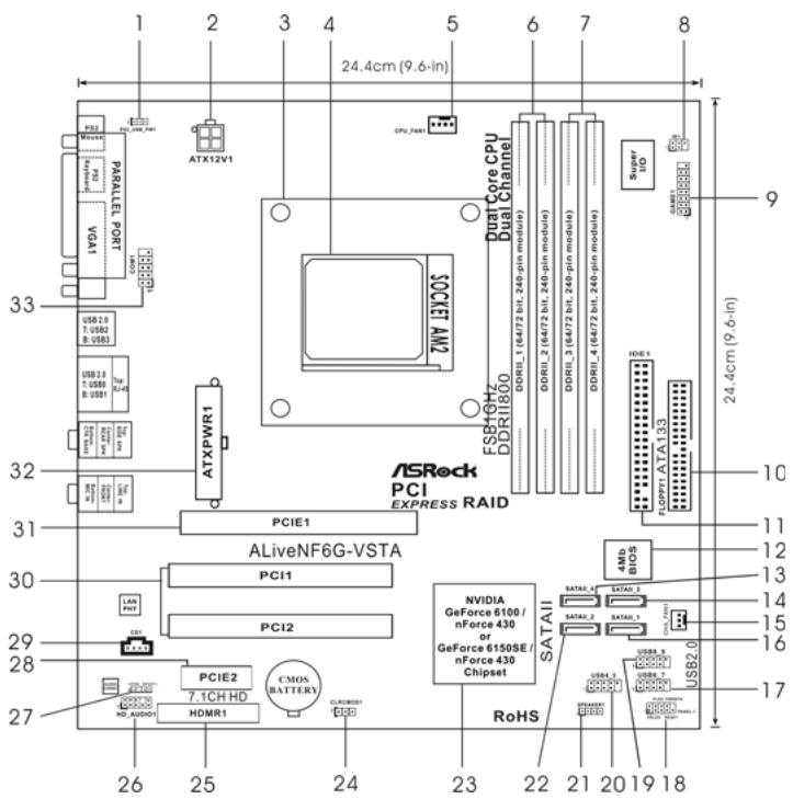
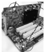
Motherboard Layout
text_image
24.4cm (9.6-in) ATX12V1 CPU PART1 P52 PARALLEL PORT NDA COM1 USB 2.0 T: USB0 B: USB0 USB 2.0 T: USB0 B: USB1 USB 2.0 T: USB0 B: USB1 ATXPWR1 ATXPRR1 ASRock PCI EXPRESS RAID Dual Core CPU Dual Channel DDRIL_1 (64/472 hit, 240-pin module) DDRIL_2 (64/472 hit, 240-pin module) DDRIL_3 (64/472 hit, 240-pin module) DDRIL_4 (64/472 hit, 240-pin module) Super HD IDE 1 FLOPPRTA ATA 133 24.4cm (9.6-in) 10 11 12 13 14 15 16 17 26 25 24 23 22 21 20 19 18 PCIE1 ALiveNF6G-VSTA PCI11 PC12 NVIDIA GeForce 6100 / nForce 430 or GeForce 6150SE / nForce 430 Chipset SATAI All 4Mb BIOS BATRA_4 BATRA_2 BATRA_1 USB_3 USB_2 USB_1 USB_0 USB_0 USB_0 USB_0 CPU/AUDIO1 HDMR1 CMOS BATTERY CLAWOS1 DOD RDORI RBOO ESR16H7 DDRII800 ATXPRW1 ATXPRW1 ATXPRW1 ATXPRW1 ATXPRW1 ATXPRW11 PS2_USB_PW1 Jumper 17 USB 2.0 Header (USB6_7, Blue)
2 ATX 12V Power Connector (ATX12V1) 18 System Panel Header (PANEL1)
3 CPU Heatsink Retention Module 19 USB 2.0 Header (USB8_9, Blue)
4 AM2 940-Pin CPU Socket 20 USB 2.0 Header (USB4_5, Blue)
5 CPU Fan Connector (CPU_FAN1) 21 Chassis Speaker Header (SPEAKER 1)
6 2 x 240-pin DDRII DIMM Slots 22 Secondary SATAII Connector
(Dual Channel A: DDRII_1, DDRII_2; Yellow) (SATAII_2, Red)
7 2 x 240-pin DDRII DIMM Slots 23 NVIDIA Single Chip
(Dual Channel B: DDRII_3, DDRII_4; Orange) 24 Clear CMOS Jumper (CLRCMOS1)
8 DeskExpress Hot Plug Detection Header 25 HDMR Slot (HDMR1)
(IR1) 26 Front Panel Audio Header (HD_AUDIO1)
9 Game Port Header (GAME1) 27 HDMI_SPDIF Header (HDMI_SPDIF1)
10 Floppy Connector (FLOPPY1) 28 PCI Express x1 Slot (PCIE2)
11 Primary IDE Connector (IDE1, Blue) 29 Internal Audio Connector: CD1 (Black)
12 Flash Memory 30 PCI Slots (PCI1-2)
13 Fourth SATAII Connector (SATAII_4, Red) 31 PCI Express x16 Slot (PCIE1)
14 Third SATAII Connector (SATAII_3, Red) 32 ATX Power Connector (ATXPWR1)
15 Chassis Fan Connector (CHA_FAN1)
16 Primary SATAII Connector (SATAII_1, Red)
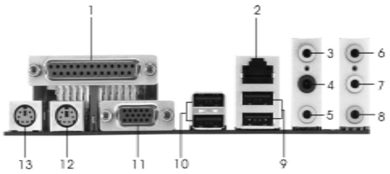
HD 8CH I/O
text_image
1 2 3 4 5 6 7 8 9 10 11 12 131 Parallel Port
2 RJ-45 Port
3 Side Speaker (Gray)
4 Rear Speaker (Black)
5 Central / Bass (Orange)
6 Line In (Light Blue)
*7 Front Speaker (Lime)
8 Microphone (Pink)
9 USB 2.0 Ports (USB01)
10 USB 2.0 Ports (USB23)
11 VGA Port
12 PS/2 Keyboard Port (Purple)
13 PS/2 Mouse Port (Green)
* If you use 2-channel speaker, please connect the speaker's plug into "Front Speaker Jack". See the table below for connection details in accordance with the type of speaker you use.
TABLE for Audio Output Connection
| Audio Output Channels | Front Speaker(No. 7) | Rear Speaker(No. 4) | Central / Bass(No. 5) | Side Speaker(No. 3) |
| 2 | V | -- | -- | -- |
| 4 | V | V | -- | -- |
| 6 | V | V | V | -- |
| 8 | V | V | V | V |
* To enable Multi-Streaming function, you need to connect a front panel audio cable to the front panel audio header. After restarting your computer, you will find "Mixer" tool on your system.
Please select "Mixer ToolBox"

, click "Enable playback multi-streaming", and click
“ok”. Choose “2CH”, “4CH”, “6CH”, or “8CH” and then you are allowed to select “Realtek HDA Primary output” to use Rear Speaker, Central/Bass, and Front Speaker, or select “Realtek HDA Audio 2nd output” to use front panel audio.
1. Introduction
Thank you for purchasing ASRock ALiveNF6G-VSTA motherboard, a reliable motherboard produced under ASRock's consistently stringent quality control. It delivers excellent performance with robust design conforming to ASRock's commitment to quality and endurance.
This Quick Installation Guide contains introduction of the motherboard and step-by-step installation guide. More detailed information of the motherboard can be found in the user manual presented in the Support CD.

Because the motherboard specifications and the BIOS software might be updated, the content of this manual will be subject to change without notice. In case any modifications of this manual occur, the updated version will be available on ASRock website without further notice. You may find the latest VGA cards and CPU support lists on ASRock website as well. ASRock website http://www.asrock.com If you require technical support related to this motherboard, please visit our website for specific information about the model you are using. www.asrock.com/support/index.asp
1.1 Package Contents
1 x ASRock ALiveNF6G-VSTA Motherboard
(Micro ATX Form Factor: 9.6-in x 9.6-in, 24.4 cm x 24.4 cm)
1 x ASRock ALiveNF6G-VSTA Quick Installation Guide
1 x ASRock ALiveNF6G-VSTA Support CD
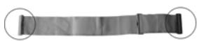
1 x Ultra ATA 66/100/133 IDE Ribbon Cable (80-conductor)
1 x 3.5-in Floppy Drive Ribbon Cable
1 x Serial ATA (SATA) Data Cable (Optional)
1 x Serial ATA (SATA) HDD Power Cable (Optional)
1 x HDMI_SPDIF Cable (Optional)
1 x HD 8CH I/O Shield
1 x COM Port Bracket
1.2 Specifications
| Platform | - Micro ATX Form Factor: 9.6-in x 9.6-in, 24.4 cm x 24.4 cm |
| CPU | - Socket AM2 for AMDAthlonTM 64FX / 64X2 / X2 / 64 and Sempron Processors- AMD LIVE!TM Ready- Supports AMD's Cool ‘n’ QuietTM Technology (seeCAUTION 1)- FSB 1000 MHz (2.0 GT/s)- Supports Untied Overclocking Technology (seeCAUTION 2)- Supports Hyper-Transport Technology |
| Chipset | - NVIDIA® GeForce 6100 / nForce 430 or GeForce 6150SE / nForce 430 (seeCAUTION 3) |
| Memory | - Dual Channel DDRII Memory Technology (seeCAUTION 4)- 4 x DDRII DIMM slots- Support DDRII800/667/533- Max. capacity: 8GB (seeCAUTION 5) |
| Hybrid Booster | - CPU Frequency Stepless Control (seeCAUTION 6)- ASRock U-COP (seeCAUTION 7)- Boot Failure Guard (B.F.G.)- ASRock AM2 Boost: ASRock Patented Technology to boost memory performance up to 12.5% (seeCAUTION 8) |
| Expansion Slot | - 2 x PCI slots- 1 x PCI Express x16 slot- 1 x PCI Express x1 slot- 1 x HDMR slot |
| Graphics | - Integrated NVIDIA® GeForce6-class graphics DX9.0 VGA- Pixel Shader 3.0- Max. shared memory 256MB |
| Audio | - 7.1 CH Windows® VistaTM Premium Level HD Audio (ALC888 Audio Codec) |
| LAN | - Realtek PHY RTL8201CL- Speed: 10/100 Ethernet- Supports Wake-On-LAN |
| Rear Panel I/O | HD 8CH I/O- 1 x PS/2 Mouse Port- 1 x PS/2 Keyboard Port- 1 x VGA Port- 1 x Parallel Port (ECP/EPP Support)- 4 x Ready-to-Use USB 2.0 Ports- 1 x RJ-45 Port |
| - HD Audio Jack: Side Speaker/Rear Speaker/Central/Bass/Line in/Front Speaker/Microphone (seeCAUTION 9) | |
| Connector | - 4 x Serial ATAll 3.0Gb/s connectors, support RAID (RAID 0, RAID 1, RAID 0+1, RAID 5, JBOD), NCQ, and “Hot Plug” functions (seeCAUTION 10)- 1 x ATA133 IDE connector (supports 2 x IDE devices)- 1 x Floppy connector- 1 x DeskExpress Hot Plug Detection header- 1 x Game header- 1 x COM port header- 1 x HDMI_SPDIF header- CPU/Chassis FAN connector- 20 pin ATX power connector- 4 pin 12V power connector- CD in header- Front panel audio connector- 3 x USB 2.0 headers (support 6 USB 2.0 ports)(seeCAUTION 11) |
| BIOS Feature | - 4Mb AMI BIOS- AMI Legal BIOS- Supports “Plug and Play”- ACPI 1.1 Compliance Wake Up Events- Supports jumperfree- SMBIOS 2.3.1 Support |
| Support CD | - Drivers, Utilities, AntiVirus Software (Trial Version) |
| Hardware Monitor | - CPU Internal Temperature Sensing- CPU Ambient Temperature Sensing- Chassis Temperature Sensing- CPU Fan Tachometer- Chassis Fan Tachometer- CPU Quiet Fan- Voltage Monitoring: +12V, +5V, +3.3V, Vcore |
| OS | - Microsoft® Windows® 2000/XP/XP Media Center/XP 64-bit/VistaTM/VistaTM 64-bit compliant |
| Certifications | - FCC, CE, Microsoft® WHQL Certificated |
WARNING
Please realize that there is a certain risk involved with overclocking, including adjusting the setting in the BIOS, applying Untied Overclocking Technology, or using the third-party overclocking tools. Overclocking may affect your system stability, or even cause damage to the components and devices of your system. It should be done at your own risk and expense. We are not responsible for possible damage caused by overclocking.
CAUTION!
- For power-saving's sake, it is strongly recommended to enable AMD's Cool 'n' Quiet™ technology under Windows system. See APPENDIX on page 50 of "User Manual" in the Support CD to enable AMD's Cool 'n' Quiet™ technology.
- This motherboard supports Untied Overclocking Technology. Please read "Untied Overclocking Technology" on page 24 for details.
- Both NVIDIA ^® GeForce 6100 / nForce 430 and GeForce 6150SE / nForce 430 refer to the same chipset. If you install NVIDIA ^® driver with 91.63 version or above under Windows ^® 2000 / XP / XP 64-bit, or install NVIDIA ^® driver with 97.19 version or above under Windows ^® Vista ^™ / Vista ^™ 64-bit, the chipset name will be GeForce 6150SE / nForce 430 instead of GeForce 6100 / nForce 430. However, the difference in device name under Windows ^® does not affect any specification and feature of this motherboard.
- This motherboard supports Dual Channel Memory Technology. Before you implement Dual Channel Memory Technology, make sure to read the installation guide of memory modules on page 10 for proper installation.
- Due to the operating system limitation, the actual memory size may be less than 4GB for the reservation for system usage under Windows® XP and Windows® Vista™. For Windows® XP 64-bit and Windows® Vista™ 64-bit with 64-bit CPU, there is no such limitation.
- Although this motherboard offers stepless control, it is not recommended to perform over-clocking. Frequencies other than the recommended CPU bus frequencies may cause the instability of the system or damage the CPU.
- While CPU overheat is detected, the system will automatically shutdown. Before you resume the system, please check if the CPU fan on the motherboard functions properly and unplug the power cord, then plug it back again. To improve heat dissipation, remember to spray thermal grease between the CPU and the heatsink when you install the PC system.
-
This motherboard supports ASRock AM2 Boost overclocking technology. If you enable this function in the BIOS setup, the memory performance will improve up to 12.5%, but the effect still depends on the AM2 CPU you adopt. Enabling this function will overclock the chipset/CPU reference clock. However, we can not guarantee the system stability for all CPU/DRAM configurations. If your system is unstable after AM2 Boost function is enabled, it may not be applicable to your system. You may choose to disable this function for keeping the stability of your system.
-
For microphone input, this motherboard supports both stereo and mono modes. For audio output, this motherboard supports 2-channel, 4-channel, 6-channel, and 8-channel modes. Please check the table on page 3 for proper connection.
- Before installing SATAII hard disk to SATAII connector, please read the "SATAII Hard Disk Setup Guide" on page 20 to adjust your SATAII hard disk drive to SATAII mode. You can also connect SATA hard disk to SATAII connector directly.
- Power Management for USB 2.0 works fine under Microsoft® Windows® Vista™ 64-bit / Vista™ / XP 64-bit / XP SP1 or SP2 / 2000 SP4.
1.3 Minimum Hardware Requirement Table for Windows® Vista™ Premium and Basic Logo
For system integrators and users who purchase this motherboard and plan to submit Windows® Vista™ Premium and Basic logo, please follow the below table for minimum hardware requirement.
| CPU | Sempron 2800+ |
| Memory | 512MB x 2 Dual Channel (Premium) |
| 512MB Single Channel (Basic) | |
| 256MB x 2 Dual Channel (Basic) |
* If you use onboard VGA with total system memory size 512MB and plan to submit Windows® Vista™ Basic logo, please adjust the shared memory size of onboard VGA to 64MB. If you use onboard VGA with total system memory size above 512MB and plan to submit Windows® Vista™ Premium or Basic logo, please adjust the shared memory size of onboard VGA to 128MB or above.
* If you plan to use external graphics card on this motherboard, please refer to Premium Discrete requirement at http://www.asrock.com
2. Installation
Pre-installation Precautions
Take note of the following precautions before you install motherboard components or change any motherboard settings.
- Unplug the power cord from the wall socket before touching any component. Failure to do so may cause severe damage to the motherboard, peripherals, and/or components.
- To avoid damaging the motherboard components due to static electricity, NEVER place your motherboard directly on the carpet or the like. Also remember to use a grounded wrist strap or touch a safety grounded object before you handle components.
- Hold components by the edges and do not touch the ICs.
- Whenever you uninstall any component, place it on a grounded antstatic pad or in the bag that comes with the component.
- When placing screws into the screw holes to secure the motherboard to the chassis, please do not over-tighten the screws! Doing so may damage the motherboard.
2.1 CPU Installation
Step 1. Unlock the socket by lifting the lever up to a 90^ angle.
Step 2. Position the CPU directly above the socket such that the CPU corner with the golden triangle matches the socket corner with a small triangle.
Step 3. Carefully insert the CPU into the socket until it fits in place.

The CPU fits only in one correct orientation. DO NOT force the CPU into the socket to avoid bending of the pins.
Step 4. When the CPU is in place, press it firmly on the socket while you push down the socket lever to secure the CPU. The lever clicks on the side tab to indicate that it is locked.
Step 5. Install CPU fan and heatsink. For proper installation, please kindly refer to the instruction manuals of your CPU fan and heatsink vendors.
2.2 Installation of Memory Modules (DIMM)
This motherboard provides four 240-pin DDRII (Double Data Rate II) DIMM slots, and supports Dual Channel Memory Technology. For dual channel configuration, you always need to install identical (the same brand, speed, size and chip-type) DDRII DIMM pair in the slots of the same color. In other words, you have to install identical DDRII DIMM pair in Dual Channel A (DDRII_1 and DDRII_2; Yellow slots; see p.2 No.6) or identical DDRII DIMM pair in Dual Channel B (DDRII_3 and DDRII_4; Orange slots; see p.2 No.7), so that Dual Channel Memory Technology can be activated. This motherboard also allows you to install four DDRII DIMMs for dual channel configuration, and please install identical DDRII DIMMs in all four slots. You may refer to the Dual Channel Memory Configuration Table below.
Dual Channel Memory Configurations
| DDRII_1(Yellow Slot) | DDRII_2(Yellow Slot) | DDRII_3(Orange Slot) | DDRII_4(Orange Slot) | |
| (1) | Populated | Populated | - | - |
| (2) | - | - | Populated | Populated |
| (3)* | Populated | Populated | Populated | Populated |
* For the configuration (3), please install identical DDRII DIMMs in all four slots.

- If you want to install two memory modules, for optimal compatibility and reliability, it is recommended to install them in the slots of the same color. In other words, install them either in the set of yellow slots (DDRII_1 and DDRII_2), or in the set of orange slots (DDRII_3 and DDRII_4).
- If only one memory module or three memory modules are installed in the DDRII DIMM slots on this motherboard, it is unable to activate the Dual Channel Memory Technology.
- If a pair of memory modules is NOT installed in the same Dual Channel, for example, installing a pair of memory modules in DDRII_1 and DDRII_3, it is unable to activate the Dual Channel Memory Technology.
- It is not allowed to install a DDR memory module into DDRII slot; otherwise, this motherboard and DIMM may be damaged.
Installing a DIMM

Please make sure to disconnect power supply before adding or removing DIMMs or the system components.
Step 1. Unlock a DIMM slot by pressing the retaining clips outward.
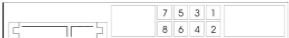
Step 2. Align a DIMM on the slot such that the notch on the DIMM matches the break on the slot.

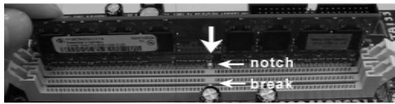
text_image
13600000000 450000000 ↓ notch Dreal

text_image
notch break
The DIMM only fits in one correct orientation. It will cause permanent damage to the motherboard and the DIMM if you force the DIMM into the slot at incorrect orientation.
Step 3. Firmly insert the DIMM into the slot until the retaining clips at both ends fully snap back in place and the DIMM is properly seated.
2.3 Expansion Slots (PCI, HDMR and PCI Express Slots)
There are 2 PCI slots, 1 HDMR slot and 2 PCI Express slots on this motherboard.
PCI slots: PCI slots are used to install expansion cards that have the 32-bit PCI interface.
HDMR slot: HDMR slot is used to insert a HDMR card (optional) with v.92 Modem functionality. The HDMR slot is shared with PCIE2 slot; you can only choose either PCIE2 slot or HDMR slot to use.
PCIE Slots: PCIE1 (PCIE x16 slot) is used for PCI Express cards with x16 lane width graphics cards.
PCIE2 (PCIE x1 slot) is used for PCI Express cards with x1 lane width cards, such as Gigabit LAN card, SATA2 card, etc.
Installing an expansion card
Step 1. Before installing the expansion card, please make sure that the power supply is switched off or the power cord is unplugged. Please read the documentation of the expansion card and make necessary hardware settings for the card before you start the installation.
Step 2. Remove the bracket facing the slot that you intend to use. Keep the screws for later use.
Step 3. Align the card connector with the slot and press firmly until the card is completely seated on the slot.
Step 4. Fasten the card to the chassis with screws.
2.4 Easy Multi Monitor Feature
This motherboard supports Multi Monitor upgrade. With the internal onboard VGA and the external add-on PCI Express VGA card, you can easily enjoy the benefits of Multi Monitor feature. Please refer to the following steps to set up a multi monitor environment:
- Install the NVIDIA® PCI Express VGA card to PCIE1 (PCIE x16 slot). Please refer to page 12 for proper expansion card installation procedures for details.
- Connect the D-Sub input monitor cable to the VGA/D-Sub port on the I/O panel of this motherboard. Connect another D-Sub input monitor cable to the VGA/D-Sub connector of the add-on PCI Express VGA card. Connect the DVI-D input monitor cable to the VGA/DVI-D connector of the add-on PCI Express VGA card.
- Boot your system. Press
to enter BIOS setup. Enter "Share Memory" option to adjust the memory capability to [16MB], [32MB], [64MB], [128MB], or [256MB] to enable the function of onboard VGA/D-sub. Please make sure that the value you select is less than the total capability of the system memory. If you do not adjust the BIOS setup, the default value of "Share Memory", [Auto], will disable onboard VGA/D-Sub function when the add-on VGA card is inserted to this motherboard. - Install the onboard VGA driver to your system. If you have installed the onboard VGA driver already, there is no need to install it again.
-
Set up a multi-monitor display. Right click the desktop, choose "Properties", and select the "Settings" tab so that you can adjust the parameters of the multi-monitor according to the steps below. (The item names and operation procedures described in this step are under Windows® XP environment. If you install other Windows® OS, the item names and operation procedures may be similar.)
A. Click the "Identify" button to display a large number on each monitor.
B. Right-click the display icon in the Display Properties dialog that you wish to be your primary monitor, and then select "Primary". When you use multiple monitors with your card, one monitor will always be Primary, and all additional monitors will be designated as Secondary.
C. Select the display icon identified by the number 2.
D. Click "Extend my Windows desktop onto this monitor".
E. Right-click the display icon and select "Attached", if necessary.
F. Set the "Screen Resolution" and "Color Quality" as appropriate for the second monitor. Click "Apply" or "OK" to apply these new values.
G. Repeat steps C through E for the display icon identified by the number one, two, and three. -
Use Multi Monitor feature. Click and drag the display icons to positions representing the physical setup of your monitors that you would like to use. The placement of display icons determines how you move items from one monitor to another.
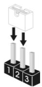
2.5 Jumpers Setup
The illustration shows how jumpers are setup. When the jumper cap is placed on pins, the jumper is "Short". If no jumper cap is placed on pins, the jumper is "Open". The illustration shows a 3-pin jumper whose pin1 and pin2 are "Short" when jumper cap is placed on these 2 pins.
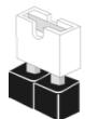
Short
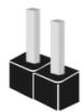
Open
Jumper
Setting
PS2_USB_PW1
(see p.2, No. 1)


Short pin2, pin3 to enable +5VSB (standby) for PS/2 or USB wake up events.
Note: To select +5VSB, it requires 2 Amp and higher standby current provided by power supply.
Clear CMOS Jumper
(CLRCMOS1)
(see p.2, No. 24)

Default

Clear CMOS
Note: CLRCMOS1 allows you to clear the data in CMOS. The data in CMOS includes system setup information such as system password, date, time, and system setup parameters. To clear and reset the system parameters to default setup, please turn off the computer and unplug the power cord from the power supply. After waiting for 15 seconds, use a jumper cap to short pin2 and pin3 on CLRCMOS1 for 5 seconds. However, please do not clear the CMOS right after you update the BIOS. If you need to clear the CMOS when you just finish updating the BIOS, you must boot up the system first, and then shut it down before you do the clear-CMOS action.
2.6 Onboard Headers and Connectors

Onboard headers and connectors are NOT jumpers. Do NOT place jumper caps over these headers and connectors. Placing jumper caps over the headers and connectors will cause permanent damage of the motherboard!
Floppy Connector
(33-pin FLOPPY1)
(see p.2 No. 10)
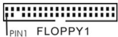
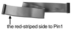
Note: Make sure the red-striped side of the cable is plugged into Pin1 side of the connector.
Primary IDE connector (Blue)
(39-pin IDE1, see p.2 No. 11)
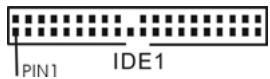
connect the blue end to the motherboard
connect the black end to the IDE devices
80-conductor ATA 66/100/133 cable
Note: Please refer to the instruction of your IDE device vendor for the details.
Serial ATAIL Connectors
(SATAII_1: see p.2, No. 16)
(SATAII_2: see p.2, No. 22)
(SATAII_3: see p.2, No. 14)
(SATAII_4: see p.2, No. 13)


These four Serial ATAIL (SATAII) connectors support SATAII or SATA hard disk for internal storage devices. The current SATAII interface allows up to 3.0 Gb/s data transfer rate.
Serial ATA (SATA)
Data Cable
(Optional)
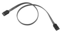
Either end of the SATA data cable can be connected to the SATA / SATAII hard disk or the SATAII connector on the motherboard.
Serial ATA (SATA)
Power Cable
(Optional)
connect to the SATA HDD power connector
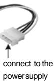
Please connect the black end of SATA power cable to the power connector on each drive. Then connect the white end of SATA power cable to the power connector of the power supply.
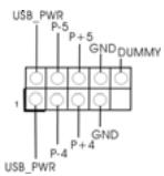
USB 2.0 Headers
(9-pin USB8_9)
(see p.2 No. 19)
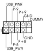
Besides four default USB 2.0 ports on the I/O panel, there are three USB 2.0 headers on this motherboard. Each USB 2.0 header can support two USB 2.0 ports.
(9-pin USB6_7)
(see p.2 No. 17)
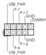
(9-pin USB4_5)
(see p.2 No. 20)
DeskExpress Hot Plug Detection
Header
(5-pin IR1)
(see p.2 No. 8)
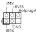
This header supports the Hot Plug detection function for ASRock DeskExpress.
Internal Audio Connectors
(4-pin CD1)
(CD1: see p.2 No. 29)
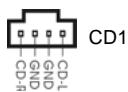
This connector allows you to receive stereo audio input from sound sources such as a CD-ROM, DVD-ROM, TV tuner card, or MPEG card.
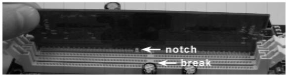
Front Panel Audio Header
(9-pin HD_AUDIO1)
(see p.2, No. 26)
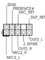
This is an interface for the front panel audio cable that allows convenient connection and control of audio devices.

- High Definition Audio supports Jack Sensing, but the panel wire on the chassis must support HDA to function correctly. Please follow the instruction in our manual and chassis manual to install your system.
- If you use AC'97 audio panel, please install it to the front panel audio header as below:
A. Connect Mic_IN (MIC) to MIC2_L.
B. Connect Audio_R (RIN) to OUT2_R and Audio_L (LIN) to OUT2_L.
C. Connect Ground (GND) to Ground (GND).
D. MIC_RET and OUT_RET are for HD audio panel only. You don't need to connect them for AC'97 audio panel.
E. Enter BIOS Setup Utility. Enter Advanced Settings, and then select Chipset Configuration. Set the Front Panel Control option from [Auto] to [Enabled].
F. Enter Windows system. Click the icon on the lower right hand taskbar to enter Realtek HD Audio Manager. Click "Audio I/O", select
"Connector Settings"
, choose "Disable front panel jack

detection", and save the change by clicking "OK".
System Panel Header
(9-pin PANEL1)
(see p.2 No. 18)

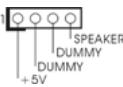
Chassis Speaker Header
(4-pin SPEAKER 1)
(see p.2 No. 21)
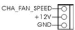
Chassis Fan Connector
(3-pin CHA_FAN1)
(see p.2 No. 15)
This header accommodates several system front panel functions.
Please connect the chassis speaker to this header.
Please connect a chassis fan cable to this connector and match the black wire to the ground pin.
CPU Fan Connector
(4-pin CPU_FAN1)
(see p.2 No. 5)
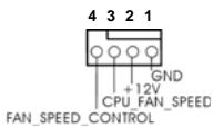
Please connect the CPU fan cable to this connector and match the black wire to the ground pin.

Though this motherboard provides 4-Pin CPU fan (Quiet Fan) support, the 3-Pin CPU fan still can work successfully even without the fan speed control function. If you plan to connect the 3-Pin CPU fan to the CPU fan connector on this motherboard, please connect it to Pin 1-3.
Pin 1-3 Connected
3-Pin Fan Installation
ATX Power Connector
(20-pin ATXPWR1)
(see p.2 No. 32)
Please connect an ATX power supply to this connector.
ATX 12V Power Connector
(4-pin ATX12V1)
(see p.2 No. 2)

Please note that it is necessary to connect a power supply with ATX 12V plug to this connector. Failing to do so will cause power up failure.
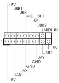
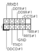
Game Port Header
(15-pin GAME1)
(see p.2 No. 9)
text_image
+5V JBB1 JBX MIDI_OUT JBY JBB2 MIDI_IN +5V JAB2 +5V JAY GND GND JAX JAB1Connect a Game cable to this header if the Game port bracket is installed.
Serial port Header
(9-pin COM1)
(see p.2 No.33)
This COM1 header supports a serial port module.
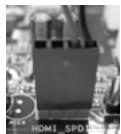
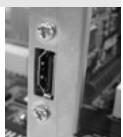
HDMI\_SPDIF Header
(3-pin HDMI_SPDIF1)
(see p.2 No. 27)

HDMI_SPDIF header, providing SPDIF audio output to HDMI VGA card, allows the system to connect HDMI Digital TV/projector/LCD devices. Please connect the HDMI_SPDIF connector of HDMI VGA card to this header.
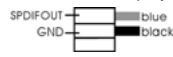
HDMI\_SPDIF Cable
(Optional)
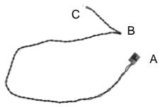
Please connect the black end (A) of HDMI_SPDIF cable to the HDMI_SPDIF header on the motherboard. Then connect the white end (B or C) of HDMI_SPDIF cable to the HDMI_SPDIF connector of HDMI VGA card.
A. black end
B. white end (2-pin)
C. white end (3-pin)
2.7 HDMI\_SPDIF Header Connection Guide
HDMI (High-Definition Multi-media Interface) is an all-digital audio/video specification, which provides an interface between any compatible digital audio/video source, such as a set-top box, DVD player, A/V receiver and a compatible digital audio or video monitor, such as a digital television (DTV). A complete HDMI system requires a HDMI VGA card and a HDMI ready motherboard with a HDMI_SPDIF header. This motherboard is equipped with a HDMI_SPDIF header, which provides SPDIF audio output to HDMI VGA card, allows the system to connect HDMI Digital TV/projector/LCD devices. To use HDMI function on this motherboard, please carefully follow the below steps.
Step 1. Install the HDMI VGA card to the PCI Express Graphics slot on this motherboard. For the proper installation of HDMI VGA card, please to the installation guide on page 12.
Step 2. Connect the black end (A) of HDMI_SPDIF cable to the HDMI_SPDIF header (HDMI_SPDIF1, yellow, see page 2, No. 27) on the motherboard.

Make sure to correctly connect the HDMI_SPDIF cable to the motherboard and the HDMI VGA card according to the same pin definition. For the pin definition of HDMI_SPDIF header and HDMI_SPDIF cable connectors, please refer to page 18. For the pin definition of HDMI_SPDIF connectors on HDMI VGA card, please refer to the user manual of HDMI VGA card vendor. Incorrect connection may cause permanent damage to this motherboard and the HDMI VGA card.
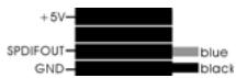
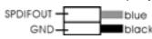
Step 3. Connect the white end (B or C) of HDMI_SPDIF cable to the HDMI_SPDIF connector of HDMI VGA card. (There are two white ends (2-pin and 3-pin) on HDMI_SPDIF cable. Please choose the appropriate white end according to the HDMI_SPDIF connector of the HDMI VGA card you install.
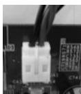
white end
(2-pin) (B)
white end (3-pin) (C)

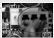
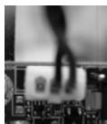
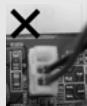
Please do not connect the white end of HDMI_SPDIF cable to the wrong connector of HDMI VGA card or other VGA card. Otherwise, the motherboard and the
VGA card may be damaged. For example, this picture shows the wrong example of connecting HDMI_SPDIF cable to the fan connector of PCI Express VGA card. Please refer to the VGA card user manual for connector usage in advance.
Step 4. Connect the HDMI output connector on HDMI VGA card to HDMI device, such as HDTV. Please refer to the user manual of HDTV and HDMI VGA card vendor for detailed connection procedures.
Step 5. Install HDMI VGA card driver to your system.
2.8 SATAII Hard Disk Setup Guide
Before installing SATAII hard disk to your computer, please carefully read below SATAII hard disk setup guide. Some default setting of SATAII hard disks may not be at SATAII mode, which operate with the best performance. In order to enable SATAII function, please follow the below instruction with different vendors to correctly adjust your SATAII hard disk to SATAII mode in advance; otherwise, your SATAII hard disk may fail to run at SATAII mode.
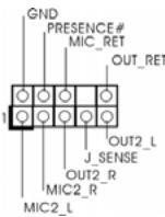
Western Digital
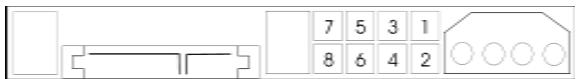
text_image
7 5 3 1 8 6 4 2If pin 5 and pin 6 are shorted, SATA 1.5Gb/s will be enabled.
On the other hand, if you want to enable SATAII 3.0Gb/s, please remove the jumpers from pin 5 and pin 6.
SAMSUNG
text_image
7 5 3 1 8 6 4 2If pin 3 and pin 4 are shorted, SATA 1.5Gb/s will be enabled.
On the other hand, if you want to enable SATAII 3.0Gb/s, please remove the jumpers from pin 3 and pin 4.
HITACHI
Please use the Feature Tool, a DOS-bootable tool, for changing various ATA features.
Please visit HITACHI's website for details:
http://www.hitachigst.com/hdd/support/download.htm

The above examples are just for your reference. For different SATAII hard disk products of different vendors, the jumper pin setting methods may not be the same. Please visit the vendors' website for the updates.
2.9 Serial ATA (SATA) / Serial ATAIL (SATAII) Hard Disks Installation
This motherboard adopts NVIDIA ^® GeForce 6100 / nForce 430 or GeForce 6150SE / nForce 430 chipset that supports Serial ATA (SATA) / Serial ATAIL (SATAII) hard disks and RAID functions. You may install SATA / SATAII hard disks on this motherboard for internal storage devices. This section will guide you to install the SATA / SATAII hard disks.
STEP 1: Install the SATA / SATAII hard disks into the drive bays of your chassis.
STEP 2: Connect the SATA power cable to the SATA / SATAII hard disk.
STEP 3: Connect one end of the SATA data cable to the motherboard's SATAII connector.
STEP 4: Connect the other end of the SATA data cable to the SATA / SATAII hard disk.
2.10 Hot Plug and Hot Swap Functions for SATA / SATAII HDDs
This motherboard supports Hot Plug and Hot Swap functions for SATA / SATAII Devices.

NOTE
What is Hot Plug Function?
If the SATA / SATAII HDDs are NOT set for RAID configuration, it is called "Hot Plug" for the action to insert and remove the SATA / SATAII HDDs while the system is still power-on and in working condition. However, please note that it cannot perform Hot Plug if the OS has been installed into the SATA / SATAII HDD.
What is Hot Swap Function?
If SATA / SATAII HDDs are built as RAID1 then it is called “Hot Swap” for the action to insert and remove the SATA / SATAII HDDs while the system is still power-on and in working condition.
2.11 Driver Installation Guide
To install the drivers to your system, please insert the support CD to your optical drive first. Then, the drivers compatible to your system can be auto-detected and listed on the support CD driver page. Please follow the order from up to bottom side to install those required drivers. Therefore, the drivers you install can work properly.
2.12 HDMR Card and Driver Installation
If you do not insert HDMR card to this motherboard, and you finish installing all drivers to your system now, but in the future, you plan to use HDMR card function on this motherboard, please follow the steps below then.
- Insert HDMR card to HDMR slot on this motherboard. Please make sure that the HDMR card is completely seated on the slot.
- Install HDMR card driver from our support CD to your system.
- Reboot your system.
2.13 Installing Windows® 2000 / XP / XP 64-bit / Vista™ / Vista™ 64-bit Without RAID Functions

The installation procedures for Windows® Vista™ / Vista™ 64-bit are subject to change. Please visit our website for the updates of Windows® Vista™ / Vista™ 64-bit driver and related information in the future.
If you just want to install Windows® 2000, Windows® XP, Windows® XP 64-bit, Windows® Vista™ or Windows® Vista™ 64-bit on your SATA / SATAII HDDs without RAID functions, you don't have to make a SATA / SATAII driver diskette. Besides, there is no need for you to change the BIOS setting. You can start to install Windows® 2000, Windows® XP, Windows® XP 64-bit, Windows® Vista™ or Windows® Vista™ 64-bit on your system directly.
2.14 Installing Windows® 2000 / XP / XP 64-bit / Vista™ / Vista™ 64-bit With RAID Functions
If you want to install Windows ^® 2000, Windows ^® XP, Windows ^® XP 64-bit, Windows ^® Vista ^™ or Windows ^® Vista ^™ 64-bit OS on your SATA / SATAII HDDs with RAID functions, please follow below procedures according to the OS you install.

- The installation procedures for Windows® Vista™ / Vista™ 64-bit are subject to change. Please visit our website for the updates of Windows® Vista™ / Vista™ 64-bit driver and related information in the future.
- Before installing Windows® 2000 to your system, your Windows® 2000 optical disk is supposed to include SP4. If there is no SP4 included in your disk, please visit the below website for proper procedures of making a SP4 disk: http://www.microsoft.com/Windows2000/downloads/servicepacks/sp4/spdeploy.htm#the_integrated_installation_fmay
2.14.1 Installing Windows® 2000 / XP / XP 64-bit With RAID Functions
If you want to install Windows ^® 2000, Windows ^® XP or Windows ^® XP 64-bit on your SATA / SATAII HDDs with RAID functions, please follow below steps.
STEP 1: Make a SATA / SATAII Driver Diskette.
A. Insert the ASRock Support CD into your optical drive to boot your system.
B. During POST at the beginning of system boot-up, press
C. When you see the message on the screen, "Generate Serial ATA driver diskette [YN]?", press
D. Then you will see these messages,
Please insert a blank
formatted diskette into floppy
 drive A:
 press any key to start
Please insert a floppy diskette into the floppy drive, and press any key.
E. The system will start to format the floppy diskette and copy SATA / SATAII drivers into the floppy diskette.
STEP 2: Set Up BIOS.
A. Enter BIOS SETUP UTILITY → Advanced screen → IDE Configuration.
B. Set the "SATA Operation Mode" option to [RAID].
STEP 3: Use "RAID Installation Guide" to set RAID configuration.
Before you start to configure RAID function, you need to check the RAID installation guide in the Support CD for proper configuration. Please refer to the BIOS RAID installation guide in the following path in the Support CD:
.. \ RAID Installation Guide
STEP 4: Install Windows ^® 2000 / Windows ^® XP / Windows ^® XP 64-bit OS on your system.
After step1, 2, 3, you can start to install Windows® 2000 / Windows® XP / Windows® XP 64-bit OS on your system. At the beginning of Windows® setup, press F6 to install a third-party RAID driver. When prompted, insert the SATA / SATAII driver diskette containing the NVIDIA® RAID driver. After reading the floppy disk, the driver will be presented. Select the driver to install according to the mode you choose and the OS you install.
NOTE. If you install Windows® 2000 / Windows® XP / Windows® XP 64-bit on IDE HDDs and want to manage (create, convert, delete, or rebuild) RAID functions on SATA / SATAII HDDs, you still need to set up “SATA Operation Mode” to [RAID] in BIOS first. Then, please set the RAID configuration by using the Windows RAID installation guide in the following path in the Support CD: .. \ RAID Installation Guide
2.14.2 Installing Windows® Vista™ / Vista™ 64-bit With RAID Functions
If you want to install Windows ^® Vista ^™ or Windows ^® Vista ^™ 64-bit on your SATA / SATAII HDDs with RAID functions, please follow below steps.
STEP 1: Set Up BIOS.
A. Enter BIOS SETUP UTILITY → Advanced screen → IDE Configuration.
B. Set the "SATA Operation Mode" option to [RAID].
STEP 2: Use "RAID Installation Guide" to set RAID configuration.
Before you start to configure RAID function, you need to check the RAID installation guide in the Support CD for proper configuration. Please refer to the BIOS RAID installation guide part of the document in the following path in the Support CD:
.. \ RAID Installation Guide
STEP 3: Install Windows® Vista™ / Windows® Vista™ 64-bit OS on your system.
Insert the Windows® Vista™ / Windows® Vista™ 64-bit optical disk into the optical drive to boot your system, and follow the instruction to install Windows® Vista™ / Windows® Vista™ 64-bit OS on your system. When you see “Where do you want to install Windows?” page, please insert the ASRock Support CD into your optical drive, and click the “Load Driver” button on the left on the bottom to load the NVIDIA® RAID drivers. NVIDIA® RAID drivers are in the following path in our Support CD:
.. \ I386 \ Vista (For Windows® Vista™ OS)
.. \ AMD64 \ Vista64 (For Windows® Vista™ 64-bit OS)
After that, please insert Windows® Vista™ / Windows® Vista™ 64-bit optical disk into the optical drive again to continue the installation.
NOTE. If you install Windows® Vista™ / Windows® Vista™ 64-bit on IDE HDDs and want to manage (create, convert, delete, or rebuild) RAID functions on SATA / SATAII HDDs, you still need to set up “SATA Operation Mode” to [RAID] in BIOS first. Then, please set the RAID configuration by using the Windows RAID installation guide in the following path in the Support CD:
.. \ RAID Installation Guide
2.15 Untied Overclocking Technology
This motherboard supports Untied Overclocking Technology, which means during overclocking, FSB enjoys better margin due to fixed PCI / PCIE buses. Before you enable Untied Overclocking function, please enter "Overclock Mode" option of BIOS setup to set the selection from [Auto] to [CPU, PCIE, Async.]. Therefore, CPU FSB is untied during overclocking, but PCI / PCIE buses are in the fixed mode so that FSB can operate under a more stable overclocking environment.

Please refer to the warning on page 7 for the possible overclocking risk before you apply Untied Overclocking Technology.
3. BIOS Information
The Flash Memory on the motherboard stores BIOS Setup Utility. When you start up the computer, please press
4. Software Support CD information
This motherboard supports various Microsoft® Windows® operating systems: 2000 / XP / XP Media Center / XP 64-bit / Vista™ / Vista™ 64-bit. The Support CD that came with the motherboard contains necessary drivers and useful utilities that will enhance motherboard features. To begin using the Support CD, insert the CD into your CD-ROM drive. It will display the Main Menu automatically if “AUTORUN” is enabled in your computer. If the Main Menu does not appear automatically, locate and double-click on the file “ASSETUP.EXE” from the “BIN” folder in the Support CD to display the menus.
1. 主板简介
www.asrock.com/support/index.asp
1.1 包装盒内物品
华擎 ALiveNF6G-VSTA 主板
text_image
O ← notch check
text_image
notch break
http://www.hitachigst.com/hdd/support/download.htm

sp4/spdeploy.htm#the integrated installation fmay
Please insert a blank
formatted diskette into floppy
drive A:
press any key to start
www.asrock.com/support/index.asp
1.1 Kartoninhalt
ASRock ALiveNF6G-VSTA Motherboard
(Micro ATX-Formfaktor: 24.4 cm x 24.4 cm; 9.6 Zoll x 9.6 Zoll)
ASRock ALiveNF6G-VSTA Schnellinstallationsanleitung
ASRock ALiveNF6G-VSTA Support-CD
| CPU | Sempron 2800+ |
| Speicher | 512 MB x 2 Dual Channel (Premium) |
| 512 MB Single Channel (Basic) | |
| 256 MB x 2 Dual Channel (Basic) |
2.1 CPU Installation
(CLRCMOS1, 3-Pin jumper)
Seriell-ATAII-Anschlüsse
http://www.microsoft.com/Windows2000/downloads/servicepacks/sp4/spdeploy.htm#the_integrated_installation_fmay
formatted diskette into floppy
drive A:
press any key to start
text_image
O ← notch ← break × ← notch ← break
Please insert a blank formatted diskette into floppy drive A:
press any key to start
(Micro ATX Form Factor: 9.6-in x 9.6-in, 24.4 cm x 24.4 cm)
text_image
O ↓ notch ← break × ↓ notch ← break
http://www.hitachigst.com/hdd/support/download.htm

formatted diskette into floppy
drive A:
press any key to start
text_image
O ↓ notch ← break × ↓ notch ← break
(CLRCMOS1, jumper de 3 pins)
(ver p.2, N. 24)
1 2

Valor predeterminado
2 3
(4-pin CD1) (CD1: vea p.2, No. 29)

Conector de audio de panel frontal
(9-pin HD_AUDIO1) (vea p.2, No. 26)
http://www.hitachigst.com/hdd/support/download.htm

formatted diskette into floppy
drive A:
press any key to start
(CLRCMOS1, jumper de 3 pinos)
Conector Áudio do painel frontal
(HD_AUDIO1 de 9 pinos)
text_image
O ↓ notch ← break × ↓ notch ← break
http://www.hitachigst.com/hdd/support/download.htm
