K8NF4G-VSTA - Motherboard ASROCK - Free user manual and instructions
Find the device manual for free K8NF4G-VSTA ASROCK in PDF.

User questions about K8NF4G-VSTA ASROCK
0 question about this device. Answer the ones you know or ask your own.
Ask a new question about this device
Download the instructions for your Motherboard in PDF format for free! Find your manual K8NF4G-VSTA - ASROCK and take your electronic device back in hand. On this page are published all the documents necessary for the use of your device. K8NF4G-VSTA by ASROCK.
USER MANUAL K8NF4G-VSTA ASROCK
No part of this installation guide may be reproduced, transcribed, transmitted, or translated in any language, in any form or by any means, except duplication of documentation by the purchaser for backup purpose, without written consent of ASRock Inc.
Products and corporate names appearing in this guide may or may not be registered trademarks or copyrights of their respective companies, and are used only for identification or explanation and to the owners' benefit, without intent to infringe.
Disclaimer:
Specifications and information contained in this guide are furnished for informational use only and subject to change without notice, and should not be constructed as a commitment by ASRock. ASRock assumes no responsibility for any errors or omissions that may appear in this guide.
With respect to the contents of this guide, ASRock does not provide warranty of any kind, either expressed or implied, including but not limited to the implied warranties or conditions of merchantability or fitness for a particular purpose.
In no event shall ASRock, its directors, officers, employees, or agents be liable for any indirect, special, incidental, or consequential damages (including damages for loss of profits, loss of business, loss of data, interruption of business and the like), even if ASRock has been advised of the possibility of such damages arising from any defect or error in the guide or product.

This device complies with Part 15 of the FCC Rules. Operation is subject to the following two conditions:
(1) this device may not cause harmful interference, and
(2) this device must accept any interference received, including interference that may cause undesired operation.
ASRock Website: http://www.asrock.com
Published March 2006
Copyright©2006 ASRock INC. All rights reserved.
Motherboard Layout
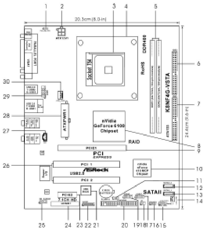
1 PS2_USB_PWM1 Jumper 16 Chassis Speaker Header (SPEAKER 1)
2 ATX 12V Power Connector (ATX12V1) 17 USB 2.0 Header (USB67, Blue)
3 754-Pin CPU Socket 18 Infrared Module Header (IR1)
4 CPU Heatsink Retention Module 19 USB 2.0 Header (USB45, Blue)
5 184-pin DDR DIMM Slots (DDR1-2) 20 Floppy Connector (FLOPPY1)
6 Secondary IDE Connector (IDE2, Black) 21 Flash Memory
7 Primary IDE Connector (IDE1, Blue) 22 Game Port Header (GAME1)
8 North Bridge Controller 23 PCI Express Slot (PCIE2)
9 PCI Express Slot (PCIE1) 24 HDMR Slot (HDMR1)
10 South Bridge Controller 25 Front Panel Audio Header (HD AUDIO01)
11 Clear CMOS Jumper (CLRCMOS2) 26 2 x PCI Slots (PCI1-2)
12 Secondary Serial ATAII Connector (SATAI_2,red) 27
13 Primary Serial ATAII Connector (SATAI_1,red)
14 Chassis Fan Connector (CHA_FAN1) 29 Serial Port Connector (COM1)
15 System Panel Header (PANEL1) 30 CPU Fan Connector (CPU_FAN1)
HD 8CH I/O
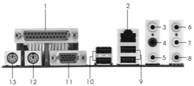
1 Parallel Port
2 RJ-45 Port
3 Side Speaker (Gray)
4 Rear Speaker (Black)
5 Central/Bass (Orange)
6 Line In (Light Blue)
*7 Front Speaker (Lime)
8 Microphone (Pink)
9 USB 2.0 Ports (USB01)
10 USB 2.0 Ports (USB23)
11 VGA Port
12 PS/2 Keyboard Port (Purple)
13 PS/2 Mouse Port (Green)
- If you use 2-channel speaker, please connect the speaker's plug into "Front Speaker Jack". See the table below for connection details in accordance with the type of speaker you use.
TABLE for Audio Output Connection
| Audio Output Channels | Front Speaker (No. 7) | Rear Speaker (No. 4) | Central / Bass (No. 5) | Side Speaker (No. 3) |
| 2 | V | -- | -- | -- |
| 4 | V | V | -- | -- |
| 6 | V | V | V | -- |
| 8 | V | V | V | V |
- To enable Multi-Streaming function, you need to connect a front panel audio cable to the front panel audio header. After restarting your computer, you will find "Mixer" tool on your system. Please select "Mixer ToolBox", click "Enable playback multi-streaming", and click
"ok". Choose "2CH", "4CH", "6CH", or "8CH" and then you are allowed to select "Realtek HDA Primary output" to use Rear Speaker, Central/Bass, and Front Speaker, or select "Realtek HDA Audio 2nd output" to use front panel audio.
1. Introduction
Thank you for purchasing ASRock K8NF4G-VSTA motherboard, a reliable motherboard produced under ASRock's consistently stringent quality control. It delivers excellent performance with robust design conforming to ASRock's commitment to quality and endurance.
This Quick Installation Guide contains introduction of the motherboard and step-by-step installation guide. More detailed information of the motherboard can be found in the user manual presented in the Support CD.

Because the motherboard specifications and the BIOS software might be updated, the content of this manual will be subject to change without notice. In case any modifications of this manual occur, the updated version will be available on ASRock website without further notice. You may find the latest VGA cards and CPU support lists on ASRock website as well.
ASRock website http://www.asrock.com
1.1 Package Contents
1 x ASRock K8NF4G-VSTA Motherboard
(Micro ATX Form Factor: 9.6-in x 8.0-in, 24.4 cm x 20.3 cm)
1 x ASRock K8NF4G-VSTA Quick Installation Guide
1 x ASRock K8NF4G-VSTA Support CD
1 x Ultra ATA 66/100/133 IDE Ribbon Cable (80-conductor)
1 x 3.5-in Floppy Drive Ribbon Cable
1 x Serial ATA (SATA) Data Cable (Optional)
1 x Serial ATA (SATA) HDD Power Cable (Optional)
1x HD 8CH I/O Shield
1x COM Port Bracket
1 x HDMR Card (Optional)
1.2 Specifications
| Platform | - Micro ATX Form Factor: 9.6-in x 8.0-in, 24.4 cm x 20.3 cm |
| CPU | - 754-Pin Socket Supporting advanced 64-bit AMD Athlon™ 64 and 32-bit/64-bit Sempron Processors - Supports AMD's Cool 'n' Quiet™ Technology (see CAUTION 1) - Chipset capable to FSB 1000 MHz (2.0 GT/s) - Supports Untied Overclocking Technology (see CAUTION 2) - Supports Hyper-Transport Technology |
| Chipset | - Northbridge: nVidia® GeForce 6100 - Southbridge: nVidia® nForce 410 MCP |
| Memory | - 2 x DDR DIMM slots - Support DDR400/333/266 - Max. capacity: 2GB |
| Hybrid Booster | - CPU Frequency Stepless Control (see CAUTION 3) - ASRock U-COP (see CAUTION 4) - Boot Failure Guard (B.F.G.) |
| Expansion Slot | - 2 x PCI slots - 1 x PCI Express x 16 slot - 1 x PCI Express x 1 slot - 1 x HDMR slot |
| Graphics | - Integrated NV44 graphics DX9.0 VGA - Pixel Shader 3.0 - Max. shared memory 128MB |
| Audio | - Realtek ALC883 7.1 channel CODEC with High Definition Audio |
| LAN | - Realtek PHY RTL8201CL - Speed: 10/100 Ethernet - Supports Wake-On-LAN |
| Rear Panel I/O | HD8CHI/O - 1 x PS/2 Mouse - 1 x PS/2 Keyboard Port - 1 x VGA Port - 1 x Parallel Port (ECP/EPP Support) - 4 x Ready-to-Use USB 2.0 Ports - 1 x RJ-45 Port - Audio Jack: Side Speaker/Rear Speaker/Central Bass/Line in/Font Speaker/Microphone (see CAUTION 5) |
| Connector | - 2 x Serial ATAII 3.0Gb/s connectors, support RAID 0, 1, JBOD (No support for “Hot Plug” function) (see CAUTION 6) - 2 x ATA133 IDE connectors (support 4 x IDE devices) - 1 x Floppy connector - 1 x IR header - 1 x Game header - 1 x COM port header - CPU/Chassis FAN connector - 20 pin ATX power connector - 4 pin 12V power connector - CD in header - Front panel audio connector - 2 x USB 2.0 headers (support 4 USB 2.0 ports) (see CAUTION 7) |
| BIOS Feature | - 4Mb AMI BIOS - AMI Legal BIOS - Supports “Plug and Play” - ACPI 1.1 Compliance Wake Up Events - Supports jumperfree - SMBIOS 2.3.1 Support |
| Support CD | - Drivers, Utilities, AntiVirus Software (Trial Version) |
| Hardware Monitor | - CPU Temperature Sensing - Motherboard Temperature Sensing - CPU Overheat Shutdown to Protect CPU Life - CPU Fan Tachometer - Chassis Fan Tachometer - CPU Quiet Fan - Voltage Monitoring: +12V, +5V, +3.3V, Vcore |
| OS | - Microsoft® Windows® 2000 / XP / XP 64-bit / Vista™ compliant (see CAUTION 8) |
| Certifications | - FCC, CE, WHQL |
CAUTION!
- For power-saving's sake, it is strongly recommended to enable AMD's Cool 'n' Quiet™ technology under Windows system. See APPENDIX on page 41 of "User Manual" in the Support CD to enable AMD's Cool 'n' Quiet™ technology. Since not all K8 754-pin CPU can support AMD's Cool 'n' Quiet™ technology, please check AMD's website for details.
- This motherboard supports Untied Overclocking Technology. Please read "Untied Overclocking Technology" on page 19 for details.
- Although this motherboard offers stepless control, it is not recommended to perform over-clocking. Frequencies other than the recommended CPU bus frequencies may cause the instability of the system or damage the CPU.
- While CPU overheat is detected, the system will automatically shutdown. Before you resume the system, please check if the CPU fan on the motherboard functions properly and unplug the power cord, then plug it back again. To improve heat dissipation, remember to spray thermal grease between the CPU and the heatsink when you install the PC system.
- For microphone input, this motherboard supports both stereo and mono modes. For audio output, this motherboard supports 2-channel, 4-channel, 6-channel, and 8-channel modes. Please check the table on page 3 for proper connection.
- Before installing SATAll hard disk to SATAll connector, please read the "SATAll Hard Disk Setup Guide" on page 16 to adjust your SATAll hard disk drive to SATAll mode. Besides, you are allowed to downgrade the SATAll hard disk to SATA hard disk (from SATAll 3Gb/s down to SATA 1.5Gb/s), and connect it to the SATAll connector. You can also connect SATA hard disk to SATAll connector directly.
- Power Management for USB 2.0 works fine under Microsoft® Windows® Vista™ / XP 64-bit / XP SP1 or SP2 / 2000 SP4.
- Microsoft® Windows® Vista™ driver is not ready yet. We will update it to our website in the future. Please visit our website for Microsoft® Windows® Vista™ driver and related information.
ASRock website http://www.asrock.com
1.3 Minimum Hardware Requirement Table for Windows® Vista™ Basic Logo
For system integrators and users who purchase our motherboard and plan to submit Windows® Vista™ Basic logo, please follow the below table for minimum hardware requirement. Please adopt the CPU, memory, and VGA that we suggest.
| CPU | Sempron 2500+ |
| Memory | 512MB Single Channel* |
| VGA | DX9.0 with WDDM Driver |
- If you use onboard VGA with total system memory size 512MB and plan to submit Windows® Vista™ Basic logo, please adjust the shared memory size of onboard VGA to 64MB or less than 64MB. If you use onboard VGA with total system memory size above 512MB and plan to submit Windows® Vista™ Basic logo, the shared memory size of onboard VGA can be adjusted up to 128MB.
2. Installation
Pre-Installation Precautions
Take note of the following precautions before you install motherboard components or change any motherboard settings.
- Unplug the power cord from the wall socket before touching any component. Failure to do so may cause severe damage to the motherboard, peripherals, and/or components.
- To avoid damaging the motherboard components due to static electricity, NEVER place your motherboard directly on the carpet or the like. Also remember to use a grounded wrist strap or touch a safety grounded object before you handle components.
- Hold components by the edges and do not touch the ICs.
- Whenever you uninstall any component, place it on a grounded antstatic pad or in the bag that comes with the component.
- When placing screws into the screw holes to secure the motherboard to the chassis, please do not over-tighten the screws! Doing so may damage the motherboard.
2.1 CPU Installation
Step 1. Unlock the socket by lifting the lever up to a 90^ angle.
Step 2. Position the CPU directly above the socket such that the CPU corner with the golden triangle matches the socket corner with a small triangle.
Step 3. Carefully insert the CPU into the socket until it fits in place.

The CPU fits only in one correct orientation. DO NOT force the CPU into the socket to avoid bending of the pins.
Step 4. When the CPU is in place, press it firmly on the socket while you push down the socket lever to secure the CPU. The lever clicks on the side tab to indicate that it is locked.
Step 5. Install CPU fan and heatsink. For proper installation, please kindly refer to the instruction manuals of your CPU fan and heatsink vendors.
2.2 Installation of Memory Modules (DIMM)
K8NF4G-VSTA motherboard provides two 184-pin DDR (Double Data Rate) DIMM slots.

Please make sure to disconnect power supply before adding or removing DIMMs or the system components.
Step 1. Unlock a DIMM slot by pressing the retaining clips outward.
Step 2. Align a DIMM on the slot such that the notch on the DIMM matches the break on the slot
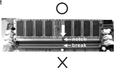
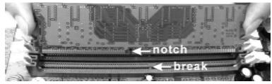

The DIMM only fits in one correct orientation. It will cause permanent damage to the motherboard and the DIMM if you force the DIMM into the slot at incorrect orientation.
Step 3. Firmly insert the DIMM into the slot until the retaining clips at both ends fully snap back in place and the DIMM is properly seated.
2.3 Expansion Slots
(PCI Express Slots, PCI Slots and HDMR Slot)
There are 2 PCI Express slots, 2 PCI slots and 1 HDMR slot on K8NF4G-VSTA motherboard.
PCIE Slots: PCIE1 (PCIE x 16 slot) is used for PCI Express cards with x16 lane width graphics cards.
PCIE2 (PCIE x 1 slot) is used for PCI Express cards, such as Gigabit LAN card, SATA2 card, etc.
PCI Slots: PCI slots are used to install expansion cards that have the 32-bit PCI interface.
HDMR slot: The HDMR slot is used to insert an ASRock HDMR card with v.92 Modem functionality. The HDMR slot is shared with PCIE2 slot; you can only choose either PCIE2 slot or HDMR slot to use.
Installing an expansion card
Step 1. Before installing the expansion card, please make sure that the power supply is switched off or the power cord is unplugged. Please read the documentation of the expansion card and make necessary hardware settings for the card before you start the installation.
Step 2. Remove the system unit cover (if your motherboard is already installed in a chassis).
Step 3. Remove the bracket facing the slot that you intend to use. Keep the screws for later use.
Step 4. Align the card connector with the slot and press firmly until the card is completely seated on the slot.
Step 5. Fasten the card to the chassis with screws.
Step 6. Replace the system cover.
2.4 Easy Multi Monitor Feature
This motherboard supports Multi Monitor upgrade. With the internal onboard VGA and the external add-on PCI Express VGA card, you can easily enjoy the benefits of Multi Monitor feature. If you plan to enable the function of onboard VGA, please enter the option "Share Memory" of BIOS to adjust the memory capability to [16MB], [32MB], [64MB], or [128MB]. Please note that the value you select should be less than the total capability of the system memory. The default value of "Share Memory" is [Auto], which will disable onboard VGA function when installing VGA card. After setting up BIOS, you can install VGA cards and VGA card drivers to enjoy multi-monitors.
2.5 Jumpers Setup
The illustration shows how jumpers are setup. When the jumper cap is placed on pins, the jumper is "Short". If no jumper cap is placed on pins, the jumper is "Open". The illustration shows a 3-pin jumper whose pin1 and pin2 are "Short" when jumper cap is placed on these 2 pins.
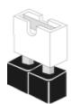
Short
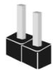
Open
Jumper Setting
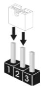
PS2_USB_PWM1
(see p.2, No. 1)


Short pin2, pin3 to enable +5VSB (standby) for PS/2 or USB wake up events.
Note: To select +5VSB, it requires 2 Amp and higher standby current provided by power supply.
Clear CMOS Jumper
(CLRCMOS2)
(see p.8, No. 11)

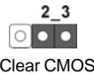
Note: CLRCMOS2 allows you to clear the data in CMOS. The data in CMOS includes system setup information such as system password, date, time, and system setup parameters. To clear and reset the system parameters to default setup, please turn off the computer and unplug the power cord from the power supply. After waiting for 15 seconds, use a jumper cap to short pin2 and pin3 on CLRCMOS2 for 5 seconds. However, please do not clear the CMOS right after you update the BIOS. If you need to clear the CMOS when you just finish updating the BIOS, you must boot up the system first, and then shut it down before you do the clear-CMOS action.
2.6 Onboard Headers and Connectors

Onboard headers and connectors are NOT jumpers. Do NOT place jumper caps over these headers and connectors. Placing jumper caps over the headers and connectors will cause permanent damage of the motherboard!
Floppy Connector
(33-pin FLOPPY1)
(see p.2 No. 20)
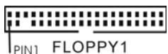
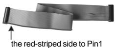
Note: Make sure the red-striped side of the cable is plugged into Pin1 side of the connector.
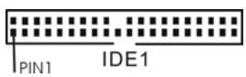
Primary IDE Connector (Blue)
(39-pin IDE1, see p.2 No. 7)
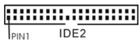
Secondary IDE Connector (Black)
(39-pin IDE2, see p.2 No. 6)
connect the blue end to the motherboard
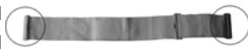
connect the black end to the IDE devices
80-conductor ATA 66/100/133 cable
Note: If you use only one IDE device on this motherboard, please set the IDE device as "Master". Please refer to the instruction of your IDE device vendor for the details. Besides, to optimize compatibility and performance, please connect your hard disk drive to the primary IDE connector (IDE1, blue) and CD-ROM to the secondary IDE connector (IDE2, black).
Serial ATA II Connectors
(SATAII_1: see p.2, No. 13)
(SATAII_2:see p.2,No.12)

SATAI2
SATAI1
These Serial ATA II (SATA II) connectors support SATA II or SATA hard disk for internal storage devices. The current SATA II interface allows up to 3.0 Gb/s data transfer rate.
Serial ATA (SATA) Data Cable
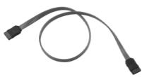
Either end of the SATA data cable can be connected to the SATA / SATAll hard disk or the SATAll connector on the motherboard.
Serial ATA (SATA)
Power Cable
(Optional)
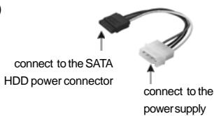
Please connect the black end of SATA power cable to the power connector on each drive. Then connect the white end of SATA power cable to the power connector of the power supply.
USB 2.0 Header
(9-pin USB67)
(see p.2 No.17)
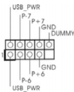
HD 8CH I/O accommo-dates 4 default USB 2.0 ports. If those USB 2.0 ports on the I/O panel are not sufficient, this USB 2.0 header is available to support 2 additional USB 2.0 ports.
USB 2.0 Header
(9-pin USB45)
(see p.2 No.19)
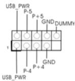
HD 8CH I/O accommo
dates 4 default USB 2.0 ports. If those USB 2.0 ports on the I/O panel are not sufficient, this USB 2.0 header is available to support 2 additional USB 2.0 ports.
Infrared Module Header
(5-pin IR1)
(see p.2 No. 18)
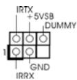
This header supports an
optional wireless transmitting
and receiving infrared module.
Internal Audio Connectors
(4-pin CD1)
(CD1: see p.2 No. 27)
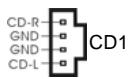
This connector allows you
to receive stereo audio input
from sound sources such as
a CD-ROM, DVD-ROM, TV
tuner card, or MPEG card.
Front Panel Audio Header
(9-pin HD=AUDIO1)
(see p.9, No.25)
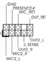
This is an interface for the front
panel audio cable that allows
convenient connection and
control of audio devices.

-
High Definition Audio supports Jack Sensing, but the panel wire on the chassis must support HDA to function correctly. Please follow the instruction in our manual and chassis manual to install your system.
-
If you use AC'97 audio panel, please install it to the front panel audio header as below:
A. Connect Mic_IN (MIC) to MIC2_L.
B. Connect Audio_R (RIN) to OUT2_R and Audio_L (LIN) to OUT2_L.
C. MIC_RET and OUT_RET are for HD audio panel only. You don't need to connect them for AC'97 audio panel.
D. Enter BIOS Setup Utility. Enter Advanced Settings, and then select Chipset Configuration. Set the Front Panel Control option from [Auto] to [Enabled].
E. Enter Windows system. Click the icon on the lower right hand taskbar to enter Realtek HD Audio Manager. Click "Audio I/O", select
"Connector Settings"

,choose“Disable front panel jack
detection", and save the change by clicking "OK".
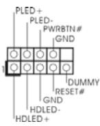
System Panel Header
(9-pin PANEL1)
(see p.2 No.15)
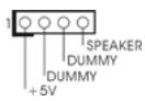
Chassis Speaker Header
(4-pin SPEAKER 1)
(see p.2 No. 16)
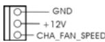
Chassis Fan Connector
(3-pin CHA_FAN1)
(see p.2 No. 14)
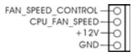
CPU Fan Connector
(4-pinCPU_FAN1)
(see p.2 No. 30)
ATX Power Connector
(20-pinATXPWR1)
(see p.2 No. 28)
ATX 12V Power Connector
(4-pin ATX12V1)
(see p.2 No. 2)

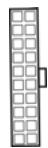
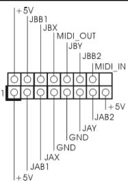
Game Port Header
(15-pin GAME1)
(see p.2 No. 22)
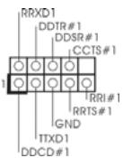
Serial port Header
(9-pin COM1)
(see p.2 item 29)
This header accommodates several system front panel functions.
Please connect the chassis speaker to this header.
Please connect a chassis fan cable to this connector and match the black wire to the ground pin.
Please connect the CPU fan cable to this connector and match the black wire to the ground pin.
Please connect an ATX power supply to this connector.
Please note that it is necessary to connect a power supply with ATX 12V plug to this connector. Failing to do so will cause power up failure.
Connect a Game cable to this header if the Game port bracket is installed.
This COM1 header supports a serial port module.
2.7 SATAll Hard Disk Setup Guide
Before installing SATAll hard disk to your computer, please carefully read below SATAll hard disk setup guide. Some default setting of SATAll hard disks may not be at SATAll mode, which operate with the best performance. In order to enable SATAll function, please follow the below instruction with different vendors to correctly adjust your SATAll hard disk to SATAll mode in advance; otherwise, your SATAll hard disk may fail to run at SATAll mode.
Western Digital

If pin 5 and pin 6 are shorted, SATA 1.5GB/s will be enabled.
On the other hand, if you want to enable SATAII 3.0GB/s, please remove the jumpers from pin 5 and pin 6.
SAMSUNG
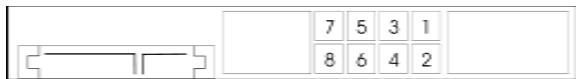
If pin 3 and pin 4 are shorted, SATA 1.5GB/s will be enabled.
On the other hand, if you want to enable SATAII 3.0GB/s, please remove the jumpers from pin 3 and pin 4.
HITACHI
Please use the Feature Tool, a DOS-bootable tool, for changing various ATA features. Please visit HITACHI's website for details:
http://www hitachigst.com/hdd/support/download.htm

The above examples are just for your reference. For different SATAll hard disk products of different vendors, the jumper pin setting methods may not be the same. Please visit the vendors' website for the updates.
2.8 Serial ATA (SATA) / Serial ATAII (SATAII) Hard Disks Installation
This motherboard adopts nVidia® nForce 410 MCP southbridge chipset that supports Serial ATA (SATA) / Serial ATAII (SATAII) hard disks and RAID functions. You may install SATA / SATAII hard disks on this motherboard for internal storage devices. This section will guide you to install the SATA / SATAII hard disks.
STEP1: Install the SATA / SATAII hard disks into the drive bays of your chassis.
STEP2: Connect the SATA power cable to the SATA / SATAll hard disk.
STEP 3: Connect one end of the SATA data cable to the motherboard's SATAI connector.
STEP4: Connect the other end of the SATA data cable to the SATA / SATAll hard disk.
2.9 HDMR Card Driver Installation
When you install the drivers to your system, please make sure to install Realtek Audio driver before installing HDMR card driver; for other drivers installation, please follow the driver order in our support CD. It is suggested to install Windows® OS, Realtek Audio and HDMR drivers with the HDMR card inserted to this motherboard; in this way, there is no problem on the Audio CODEC function. However, if you install Windows® XP 64-bit OS without HDMR card inserted and plan to insert the HDMR card to this motherboard, please install the Realtek Audio driver again; otherwise, the Audio CODEC will not work. If you install Windows® 2000 / XP OS without HDMR card inserted and plan to insert the HDMR card to this motherboard, you just have to restart your computer, then the Audio CODEC can work successfully.
2.10 Installing Windows® 2000 / Windows® XP / Windows® XP 64-bit / Windows® Vista™ Without RAID Functions
If you just want to install Windows® 2000, Windows® XP, Windows® XP 64-bit or Windows® Vista™ on your SATA / SATAAll HDDs without RAID functions, you don't have to make a SATA / SATAll driver diskette. Besides, there is no need for you to change the BIOS setting. You can start to install Windows® 2000, Windows® XP, Windows® XP 64-bit or Windows® Vista™ on your system directly.
2.11 Installing Windows® 2000 / Windows® XP / Windows® XP 64-bit / Windows® Vista™ With RAID Functions
If you want to install Windows® 2000, Windows® XP, Windows® XP 64-bit or Windows® Vista™ on your SATA / SATAAll HDDs with RAID functions, please follow the below steps.

Before installing Windows® 2000 to your system, your disk is supposed to include SP4. If there is no SP4 included in your disk, please visit the below website for proper procedures of making a SP4 disk: http://www.microsoft.com/Windows2000/downloads/servicepacks/sp4/ spdeploy.htm#the_integrated_installation_fmay
STEP 1: Make a SATA / SATAll Driver Diskette.
A. Insert the ASRock Support CD into your optical drive to boot your system.
B. During POST at the beginning of system boot-up, press <F11> key, and then a window for boot devices selection appears. Please select CD-ROM as the boot device.
C. When you see the message on the screen, "Do you want to generate Serial ATA driver diskette [YN]?", press
D. Then you will see these messages,
Please insert a diskette into the floppy drive.
WARNING! Formatting the floppy diskette will
lose ALL data in it!
Start to format and copy files [YN]?
Please insert a floppy diskette into the floppy drive, and press
E. The system will start to format the floppy diskette and copy SATA / SATAII drivers into the floppy diskette.
STEP 2: Set Up BIOS.
A. Enter BIOS SETUP UTILITY Advanced screen IDE Configuration.
B. Set the "SATAII Operation Mode" option from [non-RAID] to [RAID].
STEP 3: Use "RAID Installation Guide" to set RAID configuration.

Before you start to configure the RAID function, you need to check the installation guide in the Support CD for proper configuration. Please refer to the document in the Support CD, "Guide to SATA Hard Disks Installation and RAID Configuration", which is located in the folder at the following path: ..\InformationManual\RAID Installation Guide
After step1, 2, 3, you can start to install Windows® 2000 / Windows® XP / Windows® XP 64-bit / Windows® Vista™.
NOTE. If you install Windows® 2000 / Windows® XP / Windows® XP 64-bit / Windows® Vista™ on IDE HDDs and want to manage (create, convert, delete, or rebuild) RAID functions on SATA / SATAAll HDDs, you still need to set up "SATAll Operation Mode" to [RAID] first. Then, please set the RAID configuration by using "RAID Utility for Windows Guide" in Windows® environment. Please refer to the document in the Support CD, "Guide to nVidia RAID Utility for Windows", which is located in the folder at the following path: ..\InformationManual\RAID Utility for Windows Guide
2.12 Untied Overclocking Technology
This motherboard supports Untied Overclocking Technology, which means during overclocking, FSB enjoys better margin due to fixed PCI / PCIE buses. Before you enable Untied Overclocking function, please enter "Overclock Mode" option of BIOS setup to set the selection from [Auto] to [CPU, PCIE, Async.]. Therefore, CPU FSB is untied during overclocking, but PCI and PCIE buses are in the fixed mode so that FSB can operate under a more stable overclocking environment.
3. BIOS Information
The Flash Memory on the motherboard stores BIOS Setup Utility. When you start up the computer, please press
The BIOS Setup program is designed to be user-friendly. It is a menu-driven program, which allows you to scroll through its various sub-menus and to select among the predetermined choices. For the detailed information about BIOS Setup, please refer to the User Manual (PDF file) contained in the Support CD.
4. Software Support CD information
This motherboard supports various Microsoft® Windows® operating systems: 2000 / XP / XP 64-bit / Vista™. The Support CD that came with the motherboard contains necessary drivers and useful utilities that will enhance motherboard features.
To begin using the Support CD, insert the CD into your CD-ROM drive. It will display the Main Menu automatically if "AUTORUN" is enabled in your computer. If the Main Menu does not appear automatically, locate and double-click on the file "ASSETUP.EXE" from the "BIN" folder in the Support CD to display the menus.
1.主板简介
2.4 Easy Multi Monitor Feature
(简易的多头显示功能)
Please insert diskette into the floppy drive.
WARNING! Formatting the floppy diskette will lose ALL data in it!
Start to format and copy files [Y/N]
意即“请将一张磁盘插入软驱。
警告!格式化软盘将丢失其中所有的数据!
开始格式化和复制文件吗?”
ASRock K8NF4G-VSTA Motherboard
(Micro ATX-Formfaktor: 24.4 cm x 20.3 cm; 9.6 Zoll x 8.0 Zoll)
ASRock K8NF4G-VSTA Support-CD
2.1 CPU Installation
(CLRCMOS2, 3-Pin jumper)
(siehe S.2 -Nr. 11)

Default-Einstellung

CMOS löschen
Seriell-ATAII-Anschlüsse
http://www.hitchgst.com/hdd/support/download.htm

Please insert a diskette into the floppy drive.,WARNING! Formatting the floppy diskette will lose ALL data in it!
Start to format and copy files [Y/N]?
(Micro ATX Form Factor: 9.6-in x 8.0-in, 24.4 cm x 20.3 cm)
(CLRCMOS2, jumper de 3 pins)
(ver p.2, N. 11)


Valor predeterminado


Restablecimiento de
Ja CMOS
Ambos extremos del cableSEOSEOSEOSEOSEOSEOSEOSEOSEOSEOSEOSEOSEOSEOSEOSEOSEOSEOSEOSEOSEOSEOSEOSEOSEOSEOSEOSEOSEOSEOSEOSEOSEOSEOSEOSEOSEOSEOSEOSEOSEOSEOSEOSEOSEOSEOSEOSEOSEOSEOSEOSEOSEOSEOSEOSEOSEOSEOSEOSEOSEOSEOSEOSEOSEOSEOSEOSEOSEOSEOSEOSEOSEOSEOSEOSEOSEOSEOSEOSEOSEOSEOSEOSEOSEOSEOSEOSEOSEOSEOSEOSEOSEOSEOSEOSEOSEOSEOSEOSEO SEO SEO SEO SEO SEO SEO SEO SEO SEO SEO SEO SEO SEO SEO SEO SEO SEO SEO SEO SEO SEO SEO SEO SEO SEO SEO SEO SEO SEO SEO SEO SEO SEO SEO SEO SEO SEO SEO SEO SEO SEO SEO SEO SEO SEO SEO SEO SEO SEO SEO SEO SEO SEO SEO SEO SEO SEO SEO SEO SEO SEO SEO SEO SEO SEO SEO SEO SEO SEO SEO SEO SEO SEO SEO SEO SEO SEO SEO SEO SEO SEO SEO SEO SEO SEO SEO SEO SEO SEO SEO SEO SEO SEO SEO SEO SEO SEO SEO SEO SEO
Cable de alimentacion de series ATA (SATA)
(Optional)
(CLRCMOS2, jumper de 2 pinos)
Conector Áudio do paine frontal
(HD AUDIO01 de 9 pinos)