
ML 8810 - Dot Matrix Printer OKI - Free user manual and instructions
Find the device manual for free ML 8810 OKI in PDF.
| Product type | Dot matrix printer |
| Brand | OKI |
| Model | ML 8810 |
| Dimensions (L x D x H) | 90 cm x 152.9 cm (overall depth) x 45.7 cm (minimum) |
| Weight | Not specified in the manual |
| Power supply | Power cord, grounded wall outlet |
| Power consumption | Not specified |
| Operating temperature | 5 to 40 °C |
| Operating humidity | 30 to 85% RH |
| Supported paper types | Single sheets, continuous forms, multipart (up to 8 copies) |
| Maximum paper width | 406 mm (16 in) for continuous, 364 mm (14.3 in) for sheets |
| Maximum paper thickness | 0.48 mm (0.0189 in) for multipart continuous paper |
| Paper feed methods | Front tractor, manual feed (sheets) |
| Interfaces | USB 2.0, parallel (IEEE-1284), Ethernet 10/100 Base-TX (optional) |
| Main functions | Self-test, automatic alignment, paper end detection, multipart printing |
| Ribbon cartridge | Replaceable cartridge with winding knob |
| Maintenance and cleaning | Not specified in the manual |
| Safety | Power off before opening cover; avoid connecting USB and parallel simultaneously |
| Spare parts and repairability | Ribbon cartridge, power cord; documentation included on CD |
| General information | Manual available in PDF (44 pages); email support for translation |
Frequently Asked Questions - ML 8810 OKI
User questions about ML 8810 OKI
0 question about this device. Answer the ones you know or ask your own.
Ask a new question about this device
Download the instructions for your Dot Matrix Printer in PDF format for free! Find your manual ML 8810 - OKI and take your electronic device back in hand. On this page are published all the documents necessary for the use of your device. ML 8810 by OKI.
USER MANUAL ML 8810 OKI
Installation Summary
Unpack. 1
Set Up the Printer 2
Run a Self Test. 7
Load Paper. 7
Connect to the Computer. 10
Step 1:
Unpack
Check the Contents
If any items are missing, contact your dealer immediately.
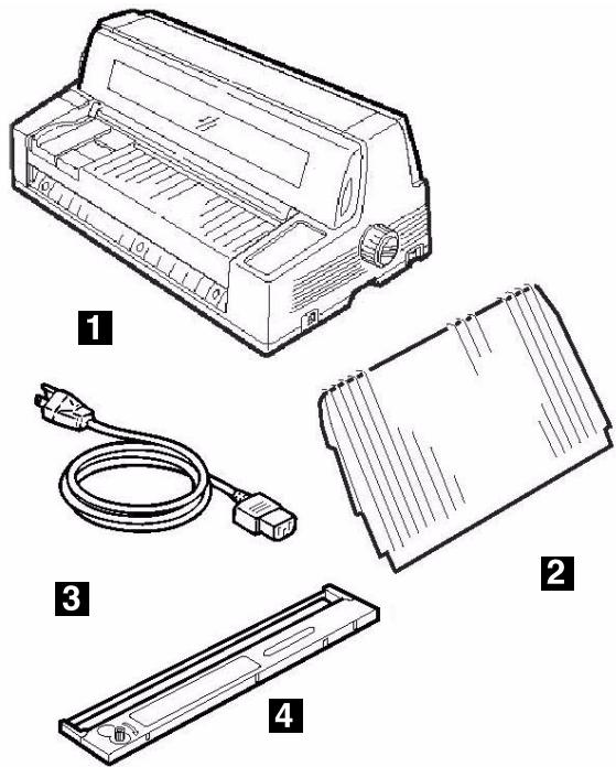
1 Printer
2 Stacker
3 Power Cable
4 Ribbon Cartridge Not illustrated: Documentation
Space Requirements
Place the printer on a stable, level surface.
Check that sufficient space is available for the installation:
- Width: 35.4" (90 cm)
- Depth
Behind printer: 23.6" (60 cm)
- In front of printer: 12.6" (32 cm)
- Overall: 60.2" (153 cm)
- Height: 18'' (46 cm) minimum
Environmental Requirements
- Operating Temperature: 41 to 104 ° F( 5to40 ° C)
- Humidity: 30 to 85% RH
Documentation
Your printer includes the following documentation:
This Setup Guide
How to get the printer up and running.
- Safety and Regulatory Information booklet
- Important safety information, along with general regulatory information (FCC, Energy Star, IC, etc.) and the Material Safety Data Sheet for the ribbon.
Printer Components
Front View
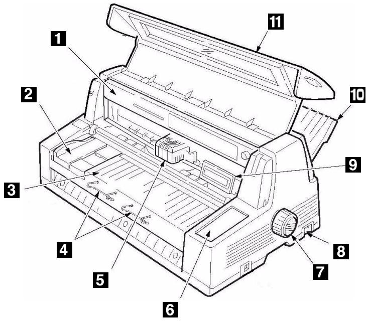
1 Ribbon Cartridge
7 Platen Knob
2 Sheet Guide
8 Power Switch
3 Sheet Platform
9 Display Panel
4 Sheet Supports
10 Stacker
5 Printhead
11 Cover
6 Control Panel
Rear View
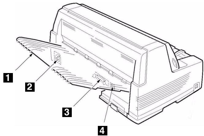
1 Stacker
3 Parallel Port
2 Power Socket
4 USB Port
Step 2:
Set Up the Printer
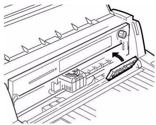
Remove the Printhead Shipping Restraint
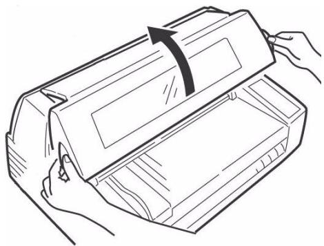
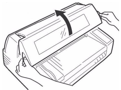
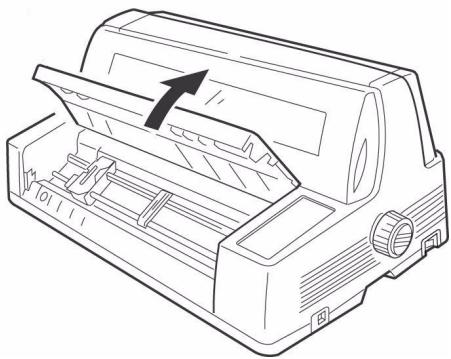
- Open the cover using the grips on either side.
- Peel the protective plastic film off the display panel.
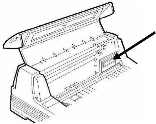
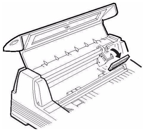
- Tilt the display panel toward you.
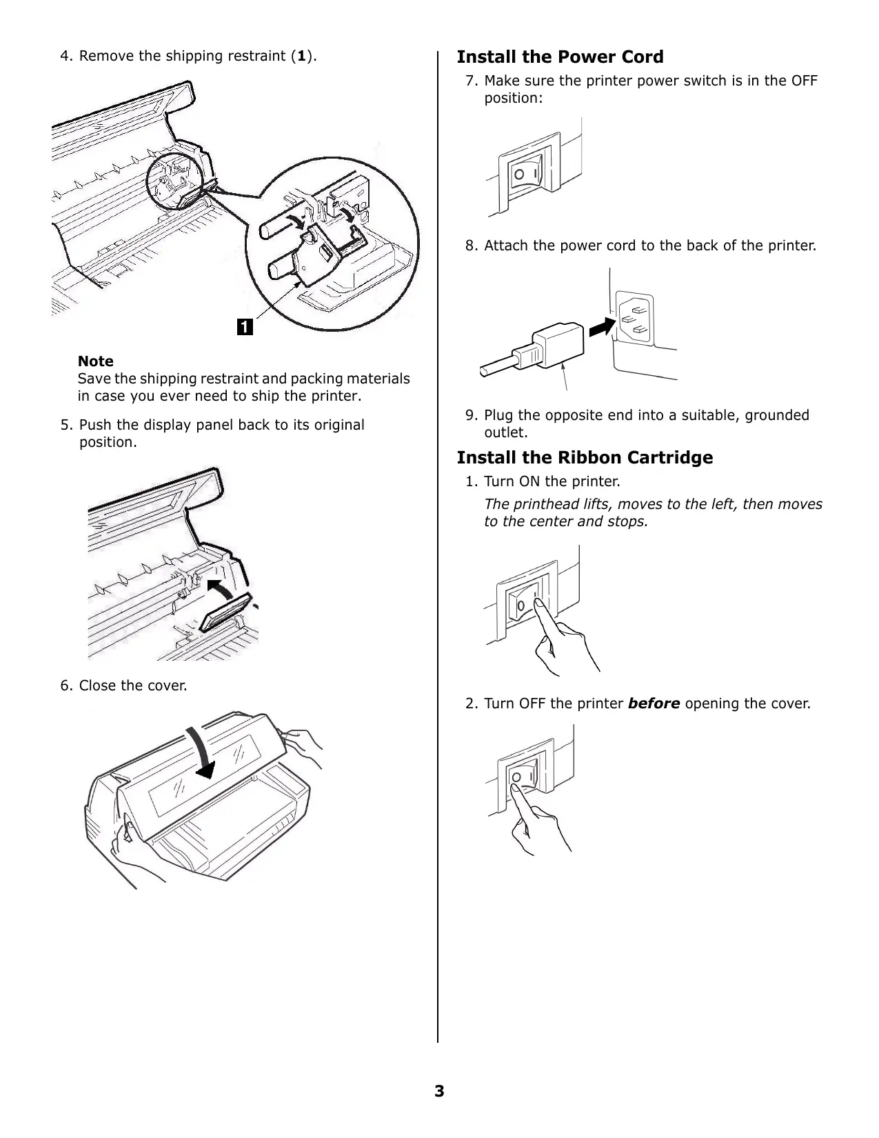
- Remove the shipping restraint (1).
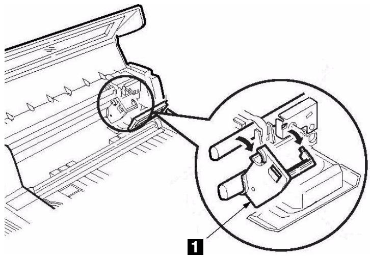
Note
Save the shipping restraint and packing materials in case you ever need to ship the printer.
- Push the display panel back to its original position.
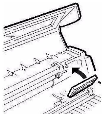
- Close the cover.
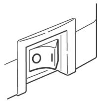
Install the Power Cord
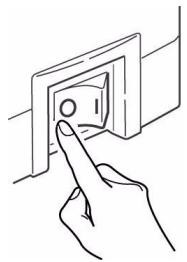
- Make sure the printer power switch is in the OFF position:
- Attach the power cord to the back of the printer.
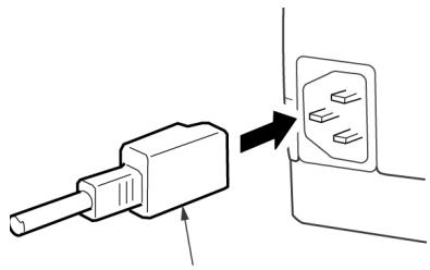
- Plug the opposite end into a suitable, grounded outlet.
Install the Ribbon Cartridge
- Turn ON the printer.
The printhead lifts, moves to the left, then moves to the center and stops.
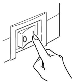
- Turn OFF the printer before opening the cover.
Warning!
Make sure the printer is turned off before you open the cover.
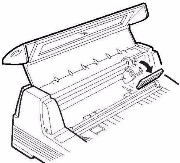
- Open the cover.
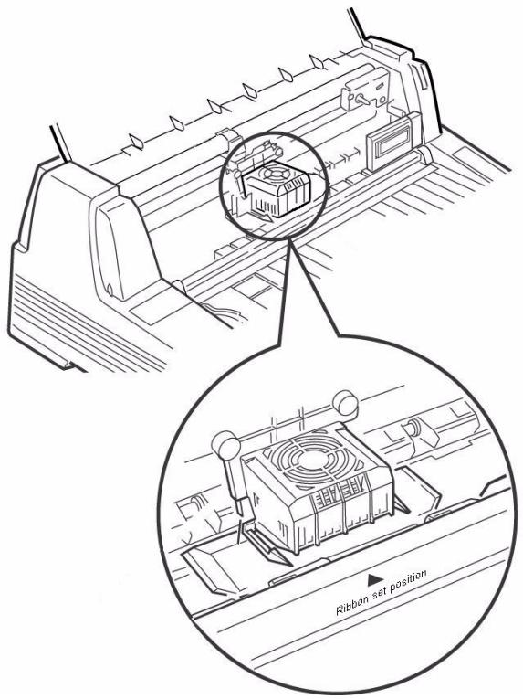
- Verify that the printhead is centered (at the "Ribbon set position").
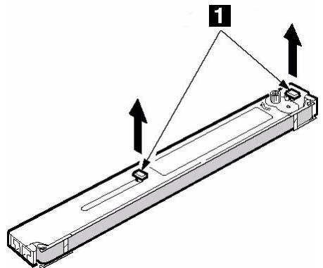
- Unpack the ribbon cartridge and remove the lock pieces (1).
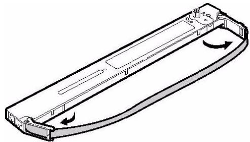
- Swing out the ribbon arms on either end of the cartridge until they snap into place.
- Tilt the display panel toward you.
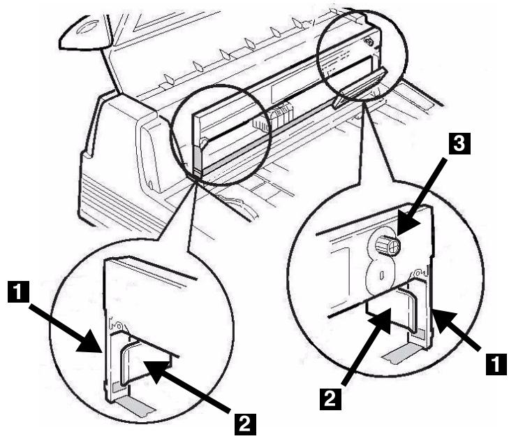
- Observe the black pin (1) over which the ribbon knob fits, and the guides (2)—one at either end—into which the ribbon arms fit.
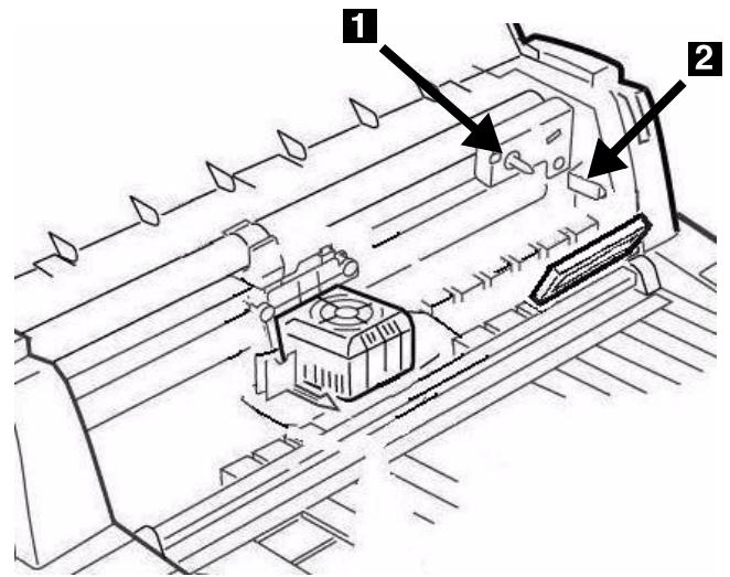
- Feed the ribbon arms (1) in beside the guides (2), position the take-up knob (3) over the pin, then press the cartridge in firmly at either end.
- Pull the ribbon out a bit at the left end of the cartridge to give some slack, then slide the ribbon underneath the printhead. Be careful that the ribbon is not twisted, folded or pulled off the ribbon arms during this process.
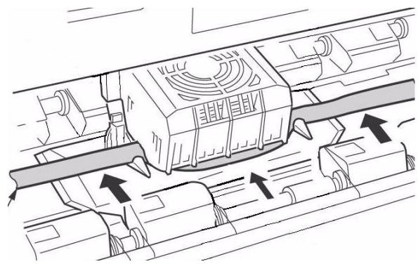
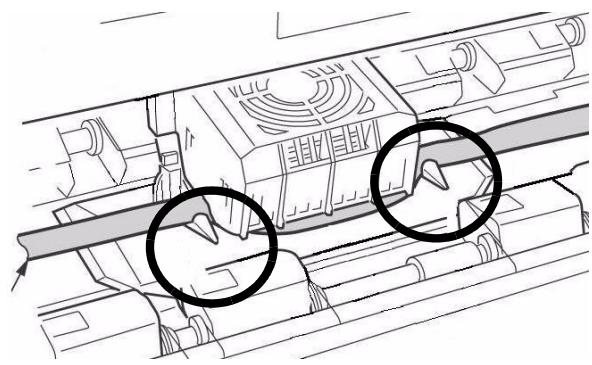
- Make sure the ribbon is threaded through the indentation in each ribbon guide arm.
Caution! Always turn the ribbon knob clockwise: turning it counterclockwise (to the left) can cause the ribbon to jam.
- Turn the ribbon knob clockwise (in the direction of the molded arrow) to take up any excess slack in the ribbon.
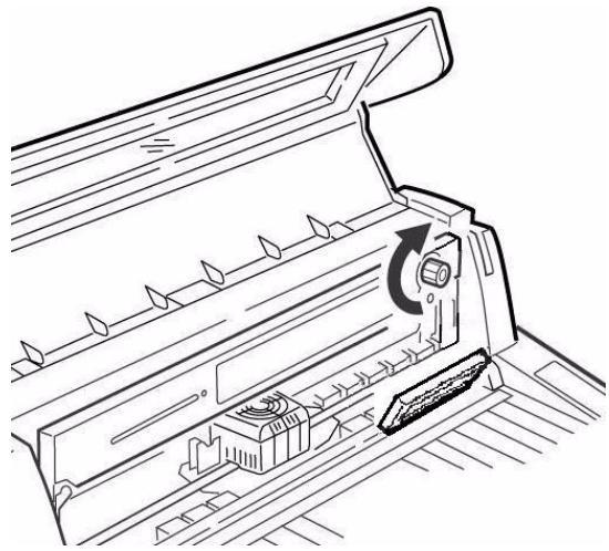
- Push the display panel back to its original position.
- Close the cover.
Caution!
If the cover does not close easily, do not force it. The right end of the ribbon cartridge is not properly seated in the printer. Open the cover and reseat it. Then reclose the cover.
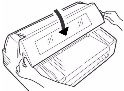
Install the Stacker
With the flat edge toward the printer and the frosted side up, slide the stacker into the channels at either end of the support, pushing it in as far as it will go.
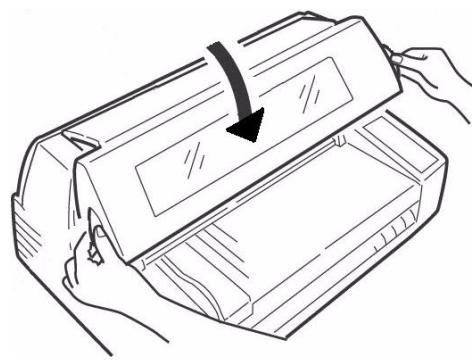
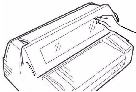
Remove the Protective Film
Peel the protective plastic film off the viewing area on the cover.
Step 3:
Run a Self Test
Before proceeding, run a self test to check that the printer is operating correctly. This prints out a list of available fonts.
- Turn off the printer.
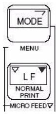
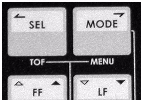
- Press and hold MODE and LF while turning on the printer. Release them when RELEASE SW appears on the second line of the display.
- When the printer finishes initializing, the display will prompt you to insert paper.
- Place a letter size or larger sheet of paper on the platform anywhere within the "Paper range when Auto Align is ON" area.
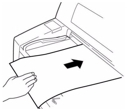
The sheet feeds in. The test prints and the page is ejected back out onto the platform.
The self test is complete.
Step 4:
Load Paper
Individual Sheets/Forms ("MANUAL")
The printer is set at the factory for
- single sheets/forms (Manual Feed)
- Auto Align mode
- automatic printhead gap (Auto Gap)
Paper Specifications, for Use with Auto Align Mode
Minimum Print Margins
1/4-inch (6.4 mm) on all sides
Individual Sheets
- Size
- Minimum Width: 3.9 ( 100 mm)
Maximum Width: 14.3" (364 mm) - Minimum Length: 2.8 ( 70 mm)
Maximum Length: 16.5'' (420 mm)
Weight
- Minimum:13.8 lb. US Bond (52 g/m²)
Maximum: 55.8 lb. US Bond (210g / m2)
Individual Multi-Part Forms
- Size
- Minimum Width: 3.9 ( 100 mm)
Maximum Width: 14.3'' (364 mm) - Minimum Length: 2.75 ( 70 mm)
Maximum Length: 16.5'' (420 mm)
- Thickness
- Up to 8-part forms (original + 7)
- Maximum Thickness: 0.0189" (0.48 mm)
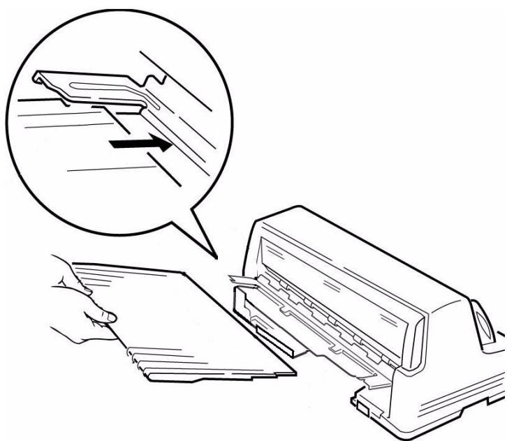
Load Individual Sheets/Forms
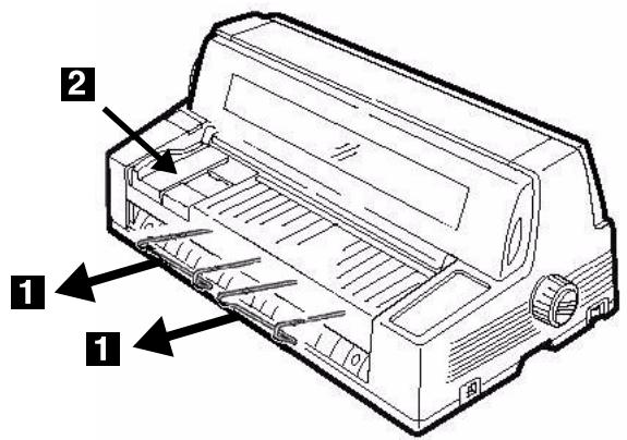
- Pull out the sheet supports (1) and move the sheet guide (2) to the right as far as it will go (the travel of the sheet guide is limited).
- Place a letter size or larger sheet/form on the platform anywhere within the "Paper range when Auto Align is ON" area
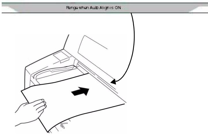
The sheet loads in to the print position, automatically aligning so that it is square with the print path.
Continuous Forms ("FRONT")
Continuous Forms Specifications
-
Width
-
Minimum: 4'' (102 mm)
Maximum: 16'' (406 mm) -
Single Thickness Forms
-
Weight range: 14 to 34 lb. US Bond (52.6 to 128g / m2 )
-
Multi-part Forms: Front Feed Tractor
-
up to 8-part forms (original + 7)
-
Maximum Thickness: 0.0189" (0.48 mm)
-
Multi-part Forms: Optional Rear Feed Tractor
-
up to 6-part forms (original + 5)
- Maximum Thickness: 0.0142 ( 0.36 mm)
Set the Printer for Continuous Forms
- If there is a sheet loaded on the platform, remove it.
- With the printer turned on, press SEL to place the printer off line.
- Press MODE once or twice until you see FRONT on the second line of the display.
The printer changes paths and returns to the on line state. FRONT appears on the second line of the display.
Note
To switch back to single sheet feed, follow the same steps, pressing MODE several times until you see MANUAL on the second line of the display.
Load Continuous Forms
- Push the sheet supports in and lift the sheet feed platform
-
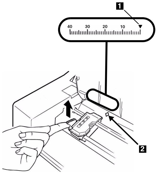
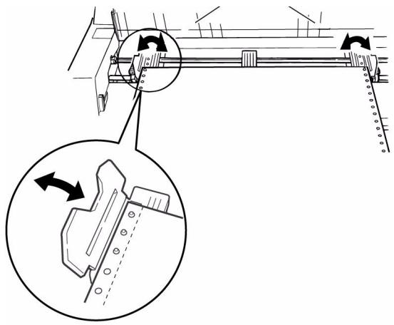
Lift the lock lever on the left tractor, then move the left tractor to set the desired left margin for printing.
-
The mark on the gauge (1)—or the center of the diamond shaped hole (2)—represents the location of the center of the first character printed.
Note
The movement of the left tractor is limited to ensure that the paper covers the paper out sensor.
-
Push the lock lever down to lock the left tractor in place.
-
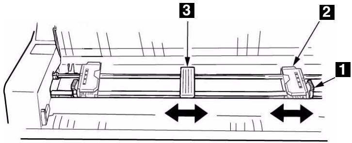
Lift the lock lever (1) on the right tractor (2) and move the tractor over to correspond to the width of the continuous forms you are using. Center the paper support (3) between the two tractors.
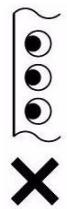
- Open both tractor covers and place the first three holes in the continuous forms paper over the pins.
Important!
Make sure that an equal number of paper holes are engaged on each tractor. If not, the paper will jam.
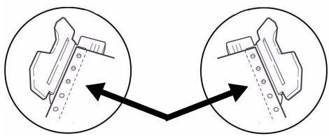
- Close the tractor covers and fine tune the position of the right tractor until the holes in the paper are centered on the pins, then push back the right tractor lock lever.


-
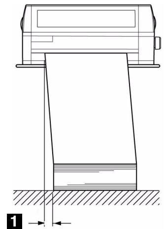
Lower the platform.
-
Position the continuous forms stack below the printer with no more than about 1 inch (3 cm) offset (1).
Tearing Off Printed Continuous Forms
- With the SEL light on, press SHIFT.
The continuous forms move forward onto the stacker.
- Tear off the printed form along the perforation.
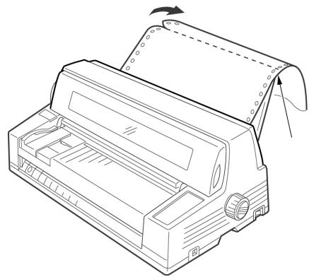
- Press SHIFT.
The forms move back into the printer, ready for printing the next document.
Removing Continuous Forms
- Follow the steps above to remove the printed portion.
- Press SEL.
- Press LOAD.
The forms move back to the tractors.
- Lift the platform and remove the forms from the tractors.
- Lower the platform.
Step 5:
Connect to the Computer
Caution!
Do not connect both the USB and parallel ports at the same time.
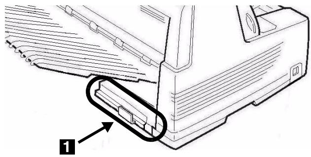
USB Port
Note
No USB interface cable is supplied with the printer. Use a USB cable that is compatible with USB specification 2.0.
- Turn off the printer.
- Connect the USB cable to the USB port on the printer.
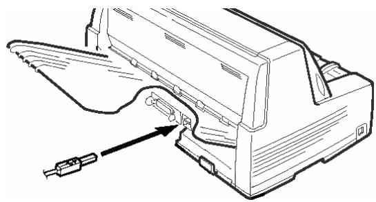
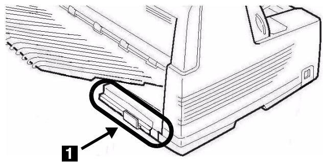
- Secure the cable in one of the channels (1) molded into the housing on either side at the back of the printer to keep it out of the way.
- Connect the USB cable to the USB port on the computer.
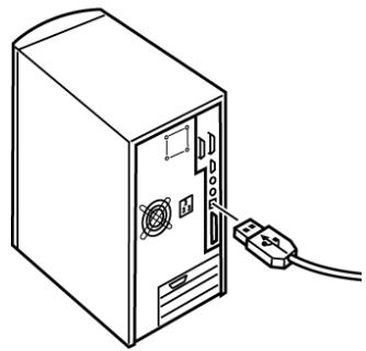
- Turn on the printer.
Parallel Port
Note
No parallel cable is supplied with the printer. Use a shielded, bi-directional, IEEE-1284 compatible, parallel cable no longer than 6 ft. (1.2 m).
- Turn off the printer.
- Connect the parallel cable to the parallel port on the printer and secure it with the wire loops.
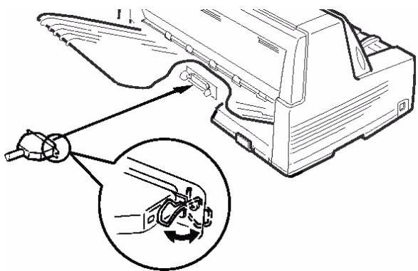
- Secure the cable in one of the channels (1) molded into the housing on either side at the back of the printer to keep it out of the way.
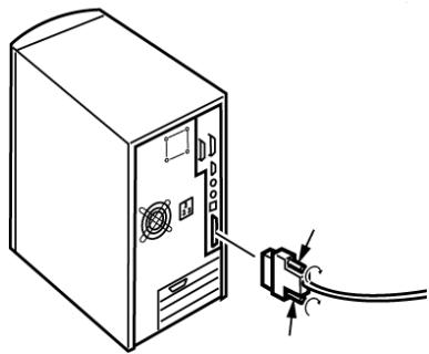
- Connect the parallel cable to the parallel port on the computer and secure it in place with the screws.
- Turn on the printer.
Network Port (Model 8810n Only)
Note
No Ethernet® cable is supplied with the printer. Use an Ethernet cable with two twisted wire pairs and an RJ45 plug.
The network print server is 10/100 Base-T Ethernet.
-
Frames
-
IEEE 802.3 and 802.3
- Ethernet-II
- SNAP
- Auto Detect
Network Protocols
- TCP/IP
-
IPX/SPX (NetWare)
-NetBEUI -
Functions
-
Self-diagnostic
- Banner supported
- Configuration by Web browser
- Notification of printer status by Email
See the on-line User's Guide on the CD supplied with your printer for more information.
To Connect the Ethernet Port
- Turn off the printer.
- Connect one end of the Ethernet cable to the 10/100B port on the back of the printer.
- Connect the other end of the Ethernet cable to the network.
MICROLINE® 8810/8810n OKI® Guide d'installation
- INSTALLATION SUMMARY
- STEP 1
- UNPACK
- CHECK THE CONTENTS
- SPACE REQUIREMENTS
- ENVIRONMENTAL REQUIREMENTS
- DOCUMENTATION
- PRINTER COMPONENTS
- FRONT VIEW
- REAR VIEW
- STEP 2
- SET UP THE PRINTER
- REMOVE THE PRINTHEAD SHIPPING RESTRAINT
- NOTE
- INSTALL THE POWER CORD
- INSTALL THE RIBBON CARTRIDGE
- CAUTION
- INSTALL THE STACKER
- REMOVE THE PROTECTIVE FILM
- STEP 3
- RUN A SELF TEST
- STEP 4
- LOAD PAPER
- INDIVIDUAL SHEETS/FORMS ("MANUAL")
- PAPER SPECIFICATIONS, FOR USE WITH AUTO ALIGN MODE
- MINIMUM PRINT MARGINS
- INDIVIDUAL SHEETS
- SIZE
- WEIGHT
- INDIVIDUAL MULTI-PART FORMS
- THICKNESS
- LOAD INDIVIDUAL SHEETS/FORMS
- CONTINUOUS FORMS ("FRONT")
- CONTINUOUS FORMS SPECIFICATIONS
- SET THE PRINTER FOR CONTINUOUS FORMS
- LOAD CONTINUOUS FORMS
- TEARING OFF PRINTED CONTINUOUS FORMS
- REMOVING CONTINUOUS FORMS
- STEP 5
- CONNECT TO THE COMPUTER
- USB PORT
- PARALLEL PORT
- NETWORK PORT (MODEL 8810N ONLY)
- TO CONNECT THE ETHERNET PORT
- MICROLINE® 8810/8810N OKI® GUIDE D'INSTALLATION
Brand : OKI
Model : ML 8810
Category : Dot Matrix Printer