
AG241 - ADSL Router LINKSYS - Free user manual and instructions
Find the device manual for free AG241 LINKSYS in PDF.

| Product Type | ADSL Router with 4-port switch |
| Brand | LINKSYS |
| Model | AG241 |
| Category | ADSL Router |
| Dimensions (approx.) | 20 x 14 x 4 cm |
| Weight (approx.) | 300 g |
| Power Supply | 12 V DC, 1 A power adapter |
| Connectivity | 1 ADSL2+ port (RJ-11), 4 Ethernet 10/100 ports (RJ-45) |
| Supported ADSL Protocols | ADSL, ADSL2, ADSL2+ |
| Supported Encapsulation | RFC 1483 Bridged, RFC 2516 PPPoE, RFC 2364 PPPoA |
| Main Functions | Router, NAT, firewall, DHCP server, 4-port switch |
| Configuration | Web interface (http://192.168.1.1) |
| Default Credentials | Username: admin, Password: admin |
| Security | SPI firewall, MAC address filtering, password change recommended |
| Operating Temperature | 0 °C to 40 °C |
| Operating Humidity | 10 % to 85 % (non-condensing) |
| Maintenance and Cleaning | Unplug before cleaning; use a soft, dry cloth. Do not use liquids or aerosols. |
| Spare Parts and Repairability | Not available; repair only by authorized service center |
| Package Contents | ADSL gateway, quick installation guide, CD-ROM (English user guide), Ethernet cable, telephone cable, power adapter, microfilters |
Frequently Asked Questions - AG241 LINKSYS
User questions about AG241 LINKSYS
0 question about this device. Answer the ones you know or ask your own.
Ask a new question about this device
Download the instructions for your ADSL Router in PDF format for free! Find your manual AG241 - LINKSYS and take your electronic device back in hand. On this page are published all the documents necessary for the use of your device. AG241 by LINKSYS.
USER MANUAL AG241 LINKSYS
Package Contents
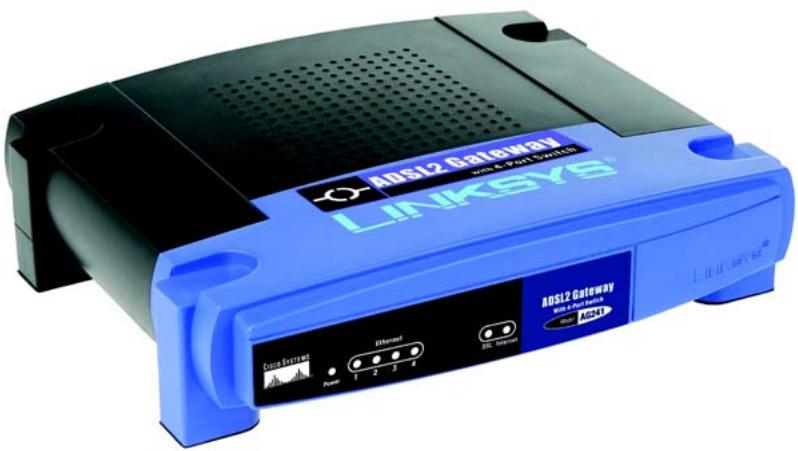
- ADSL2 Gateway
- User Guide on CD-ROM
- Ethernet Network Cable
- Phone Cable
- Power Adapter
- Microfilter or splitter (not supplied with all models)
- Quick Installation
ADSL2 Gateway
with 4-Port Switch
Quick Installation Guide
1
Connect the ADSL2 Gateway
In Step 1, you will connect the Gateway to your ADSL line and to the computers in your home or business.
First, make sure that all the devices that you'll be working with are powered down, including your PCs and the Gateway.
A
Connect one end of the provided phone cable to the wall jack with ADSL service.
NOTE: To avoid interference, you may need to place a microfilter or splitter between the phone cable and wall jack. Contact your service provider for more information.
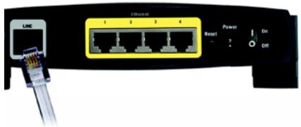
B
Connect the other end of the phone cable to the LINE port that is on the back of the Gateway.
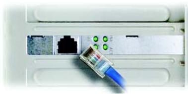
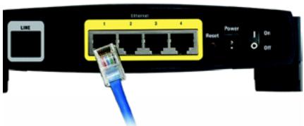
C
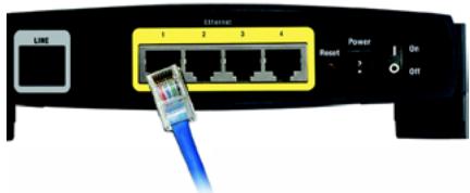
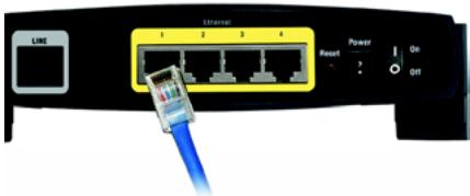
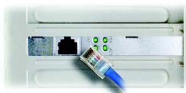
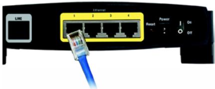
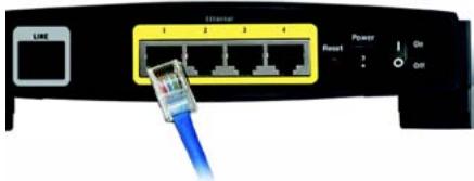
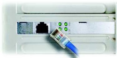
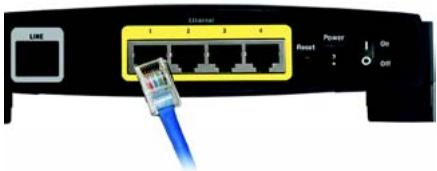
Connect one end of the provided Ethernet cable to your PC's Ethernet adapter. Connect the other end of the cable to one of the Ethernet ports on the back of the Gateway. Repeat this process for every PC that you want to connect to the Gateway. If you are connecting more than four PCs to the Gateway, you will also need to connect a hub or switch to the Gateway.
NOTE: If your PC's Ethernet adapter is not set up, refer to the Ethernet adapter's user guide for more information.
B
natural_image
Close-up of a network switch with a blue USB cable inserted, showing ports and connectors (no text or symbols visible)C1
C2
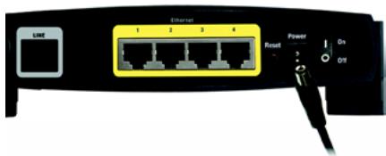
D
Connect the power adapter to the Gateway. Connect the power adapter to the electrical outlet.
E
Turn on the Gateway. Then, turn on the first PC that you want to use to configure the Gateway.
Proceed to Step 2: Configure the ADSL2 Gateway.
IMPORTANT: Make sure you only place the microfilter or splitter between the phone and the wall jack and not between the Gateway and the wall jack. Otherwise your ADSL will not connect.
D
In Step 2, you will configure the Gateway to be able to gain access to the Internet through your Internet Service Provider (ISP). You will need the setup information provided by your ADSL ISP. If you do not have this information, please contact them before proceeding.
The instructions from your ISP tell you how to set up your PC for Internet access. Because you are now using the Gateway to share Internet access among several computers, you will use the setup information to configure the Gateway instead of your PC.
NOTE: You only need to configure the Gateway once using the first computer you set up.
A
Open your web browser. (You may get an error message at this point. Continue following these directions.) Enter http://192.168.1.1 in the web browser's Address field. Press the Enter key.
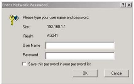
B
An Enter Network Password window will appear (Windows XP users will see a Connect to 192.168.1.1 window). Enter admin in lowercase letters in the User Name field, and enter admin in lowercase letters in the Password field (admin is the default user name and password.) Then, click the OK button.
B

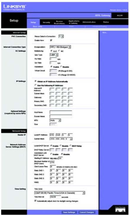
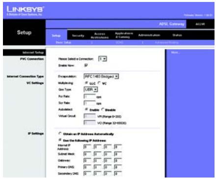
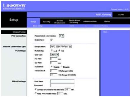
The Basic Setup screen will appear with the Setup tab selected. Based on the setup instructions from your ISP, you may need to provide the following information.
ADSL Settings. The Gateway supports five Encapsulations: RFC 1483 Bridged, RFC 1483 Routed, RFC 2516 PPPoE, RFC 2364 PPPoA, IPoA, and Bridged Mode Only. Each Basic Setup screen and available features will differ depending on what type of encapsulation you select.
VC Settings. Virtual Circuits (VPI and VCI): These fields consist of two items: VPI (Virtual Path Identifier) and VCI (Virtual Channel Identifier). Your ISP will provide the correct settings for these fields. Multiplexing: Select LLC or VC, depending on your ISP.
Your ISP will provide the correct settings.
1 RFC 1483 Bridged
Dynamic IP Address
If your ISP says that you are connecting through a dynamic IP address, perform these steps:
a
Select RFC 1483 Routed for the Encapsulation.
b
Select Obtain an IP Address Automatically for the IP Setting.
C

Dynamic IP Address
C Click the Save Settings button to save the settings.
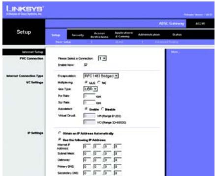
Static IP Address
If your ISP says that you are connecting through a static or fixed IP address, perform these steps:
Select RFC 1483 Bridged for the Encapsulation.
b Select Use the following IP Address as the IP Setting.
C Enter the IP Address and the Subnet Mask.
d Enter the Default Gateway address.
e Enter the DNS in the Primary and/or Secondary fields. You need to enter at least one DNS address.
f Click the Save Settings button to save the settings.
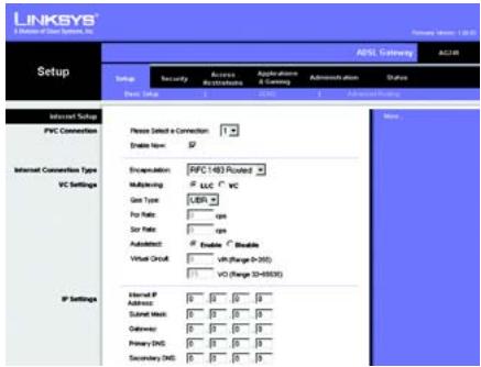
2 RFC 1483 Routed
If your ISP says that you are connecting through RFC 1483 Routed using a static IP address, perform these steps:
Select RFC 1483 Routed for the Encapsulation.
b Enter the IP Address and the Subnet Mask.
Static IP Address
RFC 1483 Routed
C Enter the Default Gateway address.
d Enter the DNS in the Primary and/or Secondary fields. You need to enter at least one DNS address.
e Click the Save Settings button to save the settings.
3 RFC 2516 PPPoE or RFC 2364 PPPoA
If your ISP says that you are connecting through PPPoE or PPPoA, or if you normally enter a user name and password to access the Internet, perform these steps:
a Select RFC2516 PPPoE or RFC 2364 PPPoA as appropriate for the Encapsulation.
b If you selected PPPoE, enter the Service Name (if required).
C Enter the User Name (if required).
d Enter the Password.
e Select Keep Alive if you always want to be connected to your ISP, or select Connect on Demand if you are charged for the time that you are connected to your ISP.
f Click the Save Settings button to save the settings.
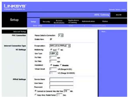
PPPoE
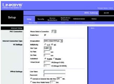
PPPoA
NOTE: PPPoE users, who require a second PPPoE by their ISP, can select Enable for Second PPPoE and enter the appropriate information for the second account.
4 IPoA
If your ISP says that you are connecting through IPoA, perform these steps:
a Select IPoA for the Encapsulation.
b Enter the IP Address and the Subnet Mask.
C Enter the Default Gateway address.
d Enter the DNS in the Primary and/or Secondary fields. You need to enter at least one DNS address.
e Click the Save Settings button to save the settings.
D If you haven't already done so, click the Save Settings button to save your Setup settings. Close the web browser.
E Congratulations! You've successfully configured the Gateway. Test the setup by opening your web browser from any computer and entering: www.linksys.com/registration
If you are unable to reach our website, you may want to review the installation and configuration sections in this Quick Installation or refer to the Troubleshooting section of the User Guide.

IPoA
LINKSYS®
A Division of Cisco Systems, Inc.
For additional information or troubleshooting help, refer to the User Guide on the CD-ROM or the Technical Support Insert. You can also e-mail for further support.
Website
http://www.linksys.com/international
Registrations
http://www.linksys.com/registration
Linksys is a registered trademark or trademark of Cisco Systems, Inc. and/or its affiliates in the U.S. and certain other countries. Copyright © 2004 Cisco Systems, Inc. All rights reserved.
AG241-EU_LA_UK-QIG-41213NC JL
Pakkens indhold
natural_image
Close-up of a router socket with a blue cable inserted, showing network ports and green indicator lights (no text or symbols visible)C1
C2
D
B
C
1 RFC 1483 Bridged
Dynamisk IP-adresse
D1 Dynamisk
![LINKSYS® Setup - 0.1.2.1.1.1.1.1.1.1.1.1.1.1.1.1.1.1.1.1.1.1.1.1.1.1.1.1.1.1.1.1.1.1.1.1.1.1.1.1.1.1.1.1.1.1.1.1.1.1.1.1.1.2 Setup Security Access Restrictions Appliances & Consigs Administration plan Status New Setup CNC Advanced Setting Internet Setup PVC Connection Please Select a Connection: Enable New: Encryption: [MPC 1483 Staged] Multiplexing: LLC VC Gen Type: UER For Rate: Size Rate: Auto detect: Enable " Enable" Virtual Grid: UH (Range: 0-300) VQ (Range: 32-6000) IP Settings Obtain an IP Address Automatically Use the following IP Address: Internal IP Address: Submit Work: Outflow: Primary DNS: Secondary DNS: More...](/content/2019/07/161464/images/48c0acea500bb8f0fd7ed75684653c4d7923977d7afd9ab5058862ec1ecdd638.jpg)
D2 Statisk
e Indtast DNS-adressen i feltet Primary og/eller Secondary. Du skal indtaste mindst én DNS-adresse.
f Klik på knappen Save Settings for at gemme indstillingerne.
2 RFC 2516 PPPoE eller RFC 2364 PPPoA
D3
PPPoE
D4
PPPoA
E
A Division of Cisco Systems, Inc.
natural_image
Close-up of a RJ46 network switch inserted into a device (no visible text or symbols)C1
C2
B


1 RFC 1483 Bridged (RFC 1483-Überbrückung)
D3
PPPoE
D4
PPPoA
A Division of Cisco Systems, Inc.
natural_image
Close-up of a network switch device showing ports, power interface, and connection port (no readable text or symbols)B
natural_image
Close-up of a white electronic device showing a RJ4 network socket connected to a blue cable (no visible text or symbols)C1

C2
B
C
1 RFC 1483 Bridged (RFC 1483 con puente)
D1
Dinámica
D2
Estática
D3 PPPoE
D4 PPPoA
A Division of Cisco Systems, Inc.
natural_image
Close-up of a white electronic device showing a RJ4 network port with green connectors and a blue USB cable inserted (no visible text or symbols)C1
C2
B

1 RFC 1483 Bridged Adresse IP dynamique
D1 Dynamique

D2 Statique
D3
PPPoE
D4
PPPoA
A Division of Cisco Systems, Inc.
natural_image
Close-up of a network switch with Ethernet port and power/switch labels (no readable text beyond symbols)B

natural_image
Close-up of a white electronic device showing a RJ4 network socket connected to a black port, with a blue cable inserted (no visible text or symbols)C1
natural_image
Close-up of a network switch with Ethernet port and power interface (no readable text or symbols)C2
B
C
1 RFC 1483 Bridged (Bridging RFC 1483)
D1 Dinamico

D2 Statico
A Division of Cisco Systems, Inc.
natural_image
Close-up of a network switch device showing Ethernet ports and power interface (no readable text or symbols)B
natural_image
Close-up of a network switch with a blue cable inserted, showing ports and connectors (no text or symbols visible)C1
natural_image
Close-up of a network switch with Ethernet ports and a blue USB cable (no visible text or symbols)C2
B
C
D1 Dinâmico

D2 Estático
D4
PPPoA
A Division of Cisco Systems, Inc.
natural_image
Close-up of a white electronic device showing a RJ4 network socket connected to a blue cable (no visible text or symbols)C1

C2
B

1 RFC 1483 Bridged (Bryggkopplad)
Dynamisk IP-adress
D1 Dynamisk

D2 Statisk
E
A Division of Cisco Systems, Inc.