USER MANUAL HR40 HONEYWELL
Installation and operating instructions
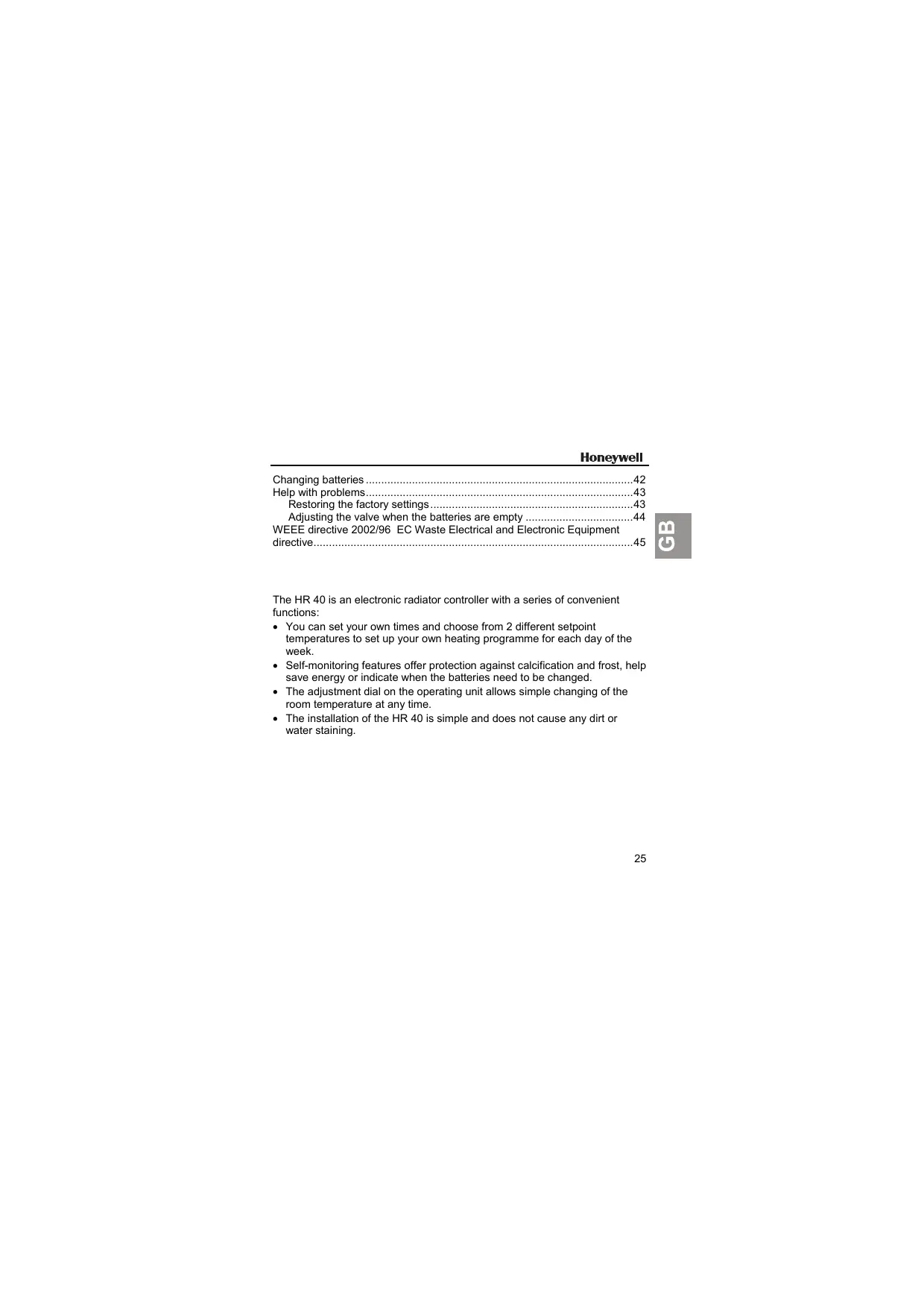
Scope of Supply: (1) Control unit including batteries
After unpacking make sure (2) Valve actuator with handwheel you have all components!
Scope of delivery 26
Installation 27
Operating elements and display 31
Automatic functions 32
Window function 32
Valve protection 32
Frost protection 32
Summer/winter time 32
Battery change display 32
Temperatures and control periods 33
Adjusting the setpoint temperature with the adjustment dial. 34
Adjusting settings 35
Changing the factory settings 35
Setting the comfort and economy temperatures 35
Changing the time program 36
Setting the week program (all days identical): 36
Setting the day program (weekdays individually): 37
38
Other setting options 39
Resetting the time and date 39
Constant temperature without time program (vacation) 40
Heating break (summer) 40
Radiator off 40
Disabling the operating elements (child-proofing) 40
Undoing the blockage of the operating elements 40
Setting the valve lift 41
Activating full-stroke mode 41
Activating the default stroke mode 41
Changing batteries 42
Help with problems 43
Restoring the factory settings 43
Adjusting the valve when the batteries are empty 44
WEEE directive 2002/96 EC Waste Electrical and Electronic Equipment
directive. 45
The HR 40 is an electronic radiator controller with a series of convenient functions:
- You can set your own times and choose from 2 different setpoint temperatures to set up your own heating programme for each day of the week.
- Self-monitoring features offer protection against calcification and frost, help save energy or indicate when the batteries need to be changed.
- The adjustment dial on the operating unit allows simple changing of the room temperature at any time.
- The installation of the HR 40 is simple and does not cause any dirt or water staining.
Scope of delivery
Operating unit including batteries (1)
Valve lantern with adjustment dial (2)
Bag containing adapter (3), screw and nut (4)
Installation
Only 4 Steps to Completion ...
It only takes a short time to install the HR 40:
- You remove the old thermostat.
- If necessary you install an adapter on the valve.
- You install the valve lantern.
- You attach the operating unit ... FINISHED!
1. Removing the old thermostat
- Loosen the mounting of the old thermostat.
- Pull the thermostat off the valve.
2. Mounting the valve adapter (optional)
- Select the right adapter from the table.
- If you need an adapter: Open up the adapter and push it onto the valve as far as the stop. Turn it while doing so until you feel it click into place.
- For the Danfoss RAV adapter: Insert the adapter pin in the valve rocker.
- If provided on the adapter: Tighten the adapter with the screw.
The Honeywell-Braukmann, MNG, Heimeier, Junkers, Landis & Gyr 'Duogyr' valves do not require an adapter. Adapters are available for Oventrop, Herz, Danfoss and Vaillant valves:
| Adapter manufacturer/type | Order No. |
| Oventrop HU 01
(knurled nut M30x1) | 073341076 |
| Herz HU 02
(knurled nut M28) | 073341725 |
| Danfoss adapter set
EVA 1-Danfoss | 072031201 |
| RA (grey) (white) (enclosed) | RAVL (black) |
| Vaillant adapter EHA 1VAI | 072031082 |
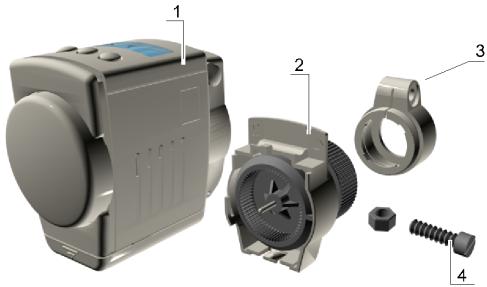
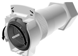
3. Installing valve lantern
- Turn the adjustment dial (3) of the valve lantern to the left until the nose (1) of the adjustment dial is positioned at the stop (2) of the housing.
- Slide the valve lantern onto the valve or adapter. The flat area on the valve lantern head must point upwards.
- Move the knurled nut forwards and tighten it firmly by hand (do not use a tool for this!).
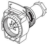

The valve is now open and, with the central heating switched on, the radiator warms through.
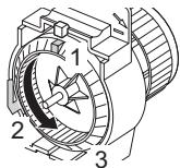
4. Inserting or removing the operating unit
- Turn the retaining bracket on the operating unit until it points upward.
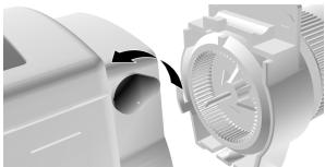
- Fit the operating unit onto the valve lantern, pushing it on as far as the stop. The flat surface of the valve lantern must be flush with the operating unit.
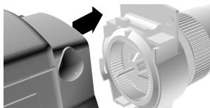
- Turn the retaining bracket on the operating unit until the tip points rearward.
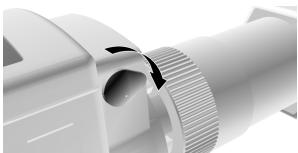
To remove the operating unit, reverse this sequence of operations.
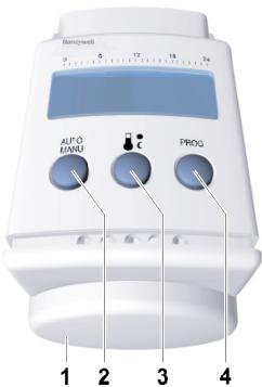
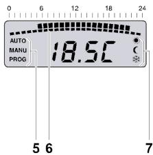
Operating elements and display
(1) Adjustment dial for setting the temperature or time
(2) AUTO button for changing between Auto and Manu mode
(3) button for setting the comfort and economy temperatures
(4) PROG button for setting the time program
(5) Operating mode: Auto, Manu or Prog
(6) Heating period in hours
(7) Comfort or economy temperature or frost protection
Automatic functions
Window function
If you open a window so that the temperature at the HR 40 drops sharply for more than 3 minutes, the HR 40 closes the radiator valve in order to save energy. The display then shows the message Open.
When the temperature rises again – but no later than after 30 minutes – the HR 40 will resume normal operation.
Note: The window function can be ended at any time by pressing the PROG button or by turning the adjustment dial.
Valve protection
In order to protect the valve it is opened every Monday at midday.
CYCL is displayed.
Frost protection
If the temperature drops below 4^ , the HR 40 opens the radiator valve until the temperature rises above 6^ again. In this way, the HR 40 prevents the radiator from freezing. The symbol flashes as soon as frost protection is activated.
Note: Frost protection only works with the operating unit attached.
Summer/winter time
The HR 40 will switch to summer or winter time automatically.
Battery change display
When the bRt display flashes, the HR 40 remains functional. However, you should change the battery as soon as possible.
If bRt is displayed permanently, the HR 40 is inactive and the radiator valve is opened (frost protection).
Temperatures and control periods
The HR 40 changes between 2 setpoint temperatures...
(at the factory 21^ )
Economy temperature:
C (at the factory 16^
... and 2 periods:
- Heating period: Set at the factory to start 6.00 a.m., heating to comfort temperature
- Economy period: Set at the factory to start 10.00 p.m., lowering to economy temperature
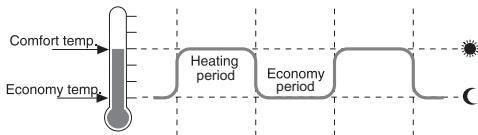
Heating and economy periods are freely adjustable. The 2nd heating and economy period is optional.
Adjusting the setpoint temperature with the adjustment dial
The adjustment dial on the operating unit can be used to adjust the setpoint temperature at any time. The setting will apply until the next programmed heating or economy period. When the adjustment dial is turned the display shows the preset setpoint temperature.
The adjustment dial does not have a stop. By turning the ring clockwise, the following settings are shown:
| Display | Setting |
| OFF | Radiator valve closed |
| 5...30 | Current setpoint temperature (poss. adjustment range) |
| On | Radiator valve fully open |
Adjusting settings
Changing the factory settings
- Set the comfort and economy temperatures.
- Set the heating and economy periods for the week program or day program.
Operating hints
- Remove the operating unit to make settings.
Press the AUTO button to cancel the programming. The HR 40 ignores the last input and returns to Auto or Manu mode.
Setting the comfort and economy temperatures
- Press the button.
- Use the adjustment dial on the operating unit to set the comfort temperature.
- Press the button.
- Use the adjustment dial to set the economy temperature.
- Press the button to confirm this change. The HR 40 then returns to Auto/Manu mode.
Changing the time program
The HR 40 has two independent time programs:
- The week program uses the same time program for all the days.
- With the day program you can set an individual time program for each weekday.
Note: Please note that two switching points each determine a heating period.
Setting the week program (all days identical):
- Press the PROG button. PROG is displayed.
- Select 1-7 using the adjustment dial.
- Confirm with the PROG button.
- Use the adjustment dial to set the 1st switching point.
- Confirm with the PROG button.
- Use the adjustment dial to set the 2nd switching point.
- Confirm with the PROG button.
- End the procedure with the AUTO button.
- or -
Set the switching points 3 and 4 for the second heating period.
The new periods are programmed.
Setting the day program (weekdays individually):
-
End the procedure with the AUTO MANU button.
-
Press the PROG button.
- Select the desired weekday with the adjustment dial. The weekdays are numbered from 1 to 7 (Monday to Sunday).
- Confirm with the PROG button.
- Use the adjustment dial to set the 1st switching point.
- Confirm with the PROG button.
- Use the adjustment dial to set the 2nd switching point.
- Confirm with the PROG button.
- Set the switching points 3 and 4 in the same way.
-or-
Select a weekday and repeat Steps 3-8.
The new periods are programmed.
Operating example
In the following example, the start of the heating period for Wednesday is set to 7.30 a.m. and the end to 10.30 p.m (22:30).
- Press the PROG button.
- Turn the adjustment dial until 3 appears in the display. Wednesday is now selected.
- Confirm the selection with the PROG button.
- Set 7:30 using the adjustment dial.
- Confirm with the PROG button.
- Set 22:30 using the adjustment dial.
- Confirm with the PROG button.
- End the procedure with the AUTO MANU button.
Deleting switching points
Note: Please note that two switching points each determine a heating period.
- Press the PROG button.
- Select all the weekdays: Set l - 7 using the adjustment dial.
-or-
Select an individual day:
select the desired weekday with the adjustment dial.
- Confirm the selection with the PROG button.
- Keep pressing the PROG button until the required switching time appears.
-
Turn the adjustment dial until ... appears in the display.
-
Confirm with the PROG button.
The switching point is deleted.
- End the procedure with the AUTO button.
-or-
In order to delete further switching points, repeat Steps 5 and 6.
Other setting options
Resetting the time and date
Note: The date and time are set at the factory. Should the batteries be empty for an extended period (nothing in the display) or if it has taken too long to change the batteries, you will need to reset the date and time.
- Hold the PROG button down for 3 seconds.
- Set the year using the adjustment dial.
- Confirm the selection with the PROG button.
- Set the month using the adjustment dial.
- Confirm with the PROG button.
- Set the day using the adjustment dial.
- Confirm with the PROG button.
- Set the hour using the adjustment dial.
- Confirm with the PROG button.
- Set the minute using the adjustment dial.
- Confirm with the PROG button.
Constant temperature without time program (vacation)
- Switch to manual mode with the AUTO button. MANU is displayed.
- Set the temperature using the adjustment dial.
This temperature is retained until you return to Auto mode.
Heating break (summer)
If the central heating system is switched off in summer, you can ensure that the batteries of the HR 40 are not wasted.
- Switch to manual mode with the AUTO MANU button.
- Turn the adjustment dial clockwise until n is displayed in the display.
The radiator valve now remains open and the HR 40 does not control.
Radiator off
- Switch to manual mode with the AUTO MANU button.
- Turn the adjustment dial anti-clockwise until UFF is displayed in the display.
The radiator valve is closed.
Note: Frost protection is still ensured.
Disabling the operating elements (child-proofing)
- Press the AUTO MANU and AUTO buttons simultaneously for 3 seconds. "bLoc" is displayed.
Undoing the blockage of the operating elements
- Press the AUTO MANU and AUTO MANU buttons simultaneously again for 3 seconds.
Setting the valve lift
The HR 40 operates with a factory setting with the optimum valve lift that is required for room temperature control.
Activating full-stroke mode
If the entire valve stroke is to be used or if the valve does not close completely, activate the full-stroke mode.
Note: The battery life is reduced through the full-stroke operating mode.
-
Remove the operating unit.
-
Press and hold the button and slide the operating unit onto the valve lantern until the stop is reached and lock.
FULL is displayed.
Activating the default stroke mode
-
Hold the PROG button down.
-
Slide the operating unit onto the valve lantern until the stop is reached and lock.
DEF is displayed.
Changing batteries
The batteries need changing when bRTT flashes on the display. The following anti-leak batteries can be used for the HR 40:
| Type | Designation | Battery life |
| Mignon battery | Alkaline-manganese LR6 AA AM3 | 2 years |
| 1.5 V accumulator | Alkaline-manganese LR6 AA AM3 | %4 year |
| Lithium battery | LR6 AA AM3 | 2 years |
Note: If changing the batteries takes a long time or the operating unit is not removed, the time will need to be reset.
- Remove the operating unit.
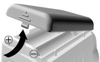
- Open the battery compartment on the underside of the operating unit.
- Remove and dispose of the used batteries.
Battery disposal
Batteries may not be disposed of with household garbage. Dispose of used batteries according to the local statutory requirements by returning them to the corresponding recycling centre.
- Insert 2 batteries into the battery compartment of the operating unit making sure the polarity is correct.
- Close the battery compartment and click it in place.
- Attach the operating unit.
Help with problems
| Problem/Display | Cause | Remedy |
| The radiator does not become cold | The valve is not closing fully | Check the installation. If appropriate, activate the full-stroke mode |
| bRIT flashes | The battery level is too low | Change the batteries as soon as possible |
| bRIT | Batteries are flat (no valve movement possible, no control, valve open) | Change the batteries immediately |
| E2 | The operating unit is not attached | Attach the operating unit correctly |
| E3 | Motor cannot be moved | Check the installation. If appropriate, remove the dirt |
| E4 | - | Please contact your local dealer |
Restoring the factory settings
- Press and hold all 3 buttons while inserting the batteries at the same time.
Adjusting the valve when the batteries are empty
- Remove the operating unit.
-
Operate the radiator valve by hand using the adjustment dial on the valve lantern:
-
hot/ - cold.
WEEE directive 2002/96
EC Waste Electrical and Electronic Equipment directive
At the end of the product life dispose of the packaging and product in a corresponding recycling centre. Do not dispose of the unit with the usual domestic refuse. Do not burn the product.
Sommaire
Pá displayet vises meddelelsen FULL.
Stookpauze (zomer) 135
Radiatoruit 135
Bedieningselementen blokkeren (kinderslot) 135
Blokkering opheffen 135
Slaginstelling 136
Volle-slag-modus activeren 136
Subject to change without notice
Manufacturing
DIN EN ISO
9001/14001 certified
This document replaces all previously issued instructions and is only applicable to the product with which it is supplied.