
SPRINTSCAN 45 ULTRA - Photo scanners POLAROID - Free user manual and instructions
Find the device manual for free SPRINTSCAN 45 ULTRA POLAROID in PDF.

| Product Type | Professional film scanner |
| Brand | Polaroid |
| Model | SprintScan 45 Ultra |
| Supported Film Types | 35 mm (mounted or unmounted), 120 (6x6, 6x7), 4x5 inches |
| Interface | SCSI (SCSI host adapter required) |
| Power Supply | Mains via included power cable |
| Included Software | PolaColor Insight for Windows and Mac |
| Included Accessories | 4x5 film holder, 120 film adapters (6x6 and 6x7), 35 mm slide adapter, four-slide holder, SCSI cable, power cable, 35 mm spacer, 120 film magnets |
| Supported Operating Systems | Windows 95, 98, NT, 2000, Me; Mac OS 7.6+ |
| Minimum Requirements (Mac) | PowerPC, 64 MB RAM, 400 MB disk space |
| Minimum Requirements (PC) | Pentium 300 MHz, 128 MB RAM, 400 MB disk space |
| Warranty | 1 year against manufacturing defects |
| Maintenance | Protect from dust, avoid vibrations, do not disassemble |
| Safety | Do not open the scanner (risk of electric shock), use shielded cable with ferrite |
| Repairability | Do not attempt to repair yourself, contact Polaroid support |
| Certifications | FCC Class B compliant |
Frequently Asked Questions - SPRINTSCAN 45 ULTRA POLAROID
User questions about SPRINTSCAN 45 ULTRA POLAROID
0 question about this device. Answer the ones you know or ask your own.
Ask a new question about this device
Download the instructions for your Photo scanners in PDF format for free! Find your manual SPRINTSCAN 45 ULTRA - POLAROID and take your electronic device back in hand. On this page are published all the documents necessary for the use of your device. SPRINTSCAN 45 ULTRA by POLAROID.
USER MANUAL SPRINTSCAN 45 ULTRA POLAROID
natural_image
Pure 3D line drawing of a mechanical part or housing (no text or symbols)Installation Quickstart
Schnelleinstieg
- A Power Macintosh computer (includes Power Macintosh G3 and G4 computers) or compatible with a PowerPC processor and 64 megabytes (MB) of RAM.
• Apple system software version 7.6 or later.
• 400 MB of free disk space. - Scratch disk space equal to twice the final image file size plus 4 MB.
- A video adapter and monitor capable of displaying thousands of colors, minimum. 24-bit color (16.7 million colors) is recommended for optimal display of scanned pictures.
PC Systems
- An IBM PC computer or compatible with at least a 300-MHz Pentium processor and 128 megabytes (MB) of RAM. (RAM equal to the typical image file size is recommended.)
- Microsoft Windows 95, 98 or NT (version 4 or later) operating system.
• 400 MB of free disk space. - An ASPI-compliant SCSI adapter with the appropriate Windows 95, 98 or NT drivers.
- A video adapter and monitor capable of displaying thousands of colors, minimum. 24-bit color (16.7 million colors) is recommended for optimal display of scanned pictures.
1 Unpack the Box
Make sure you have all the following components. Contact your dealer if any is missing or damaged.
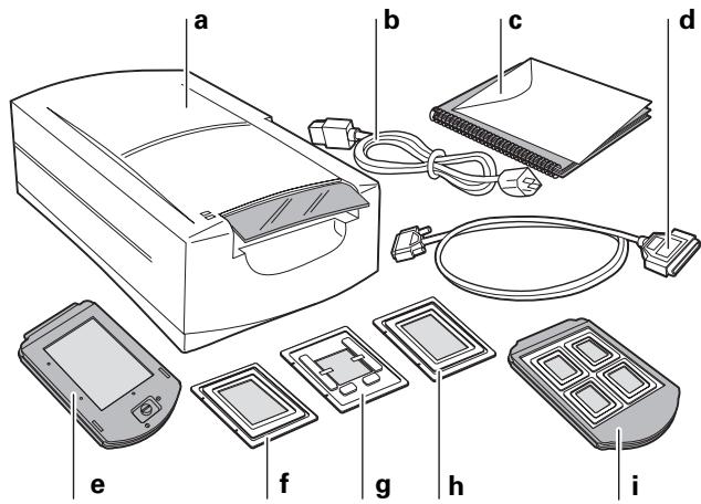
a Scanner
b Power cable (several provided for various power sources)
c This manual
d SCSI cable (25-pin to 50-pin)
e Film carrier for 4x5 film
f Adapter for 120 film, 2 1/4 x 2 1/4 in.
g Adapter for single 35mm slide
h Adapter for 120 film, 2 1/4 x 2 3/4 in.
i Four-slide film carrier
j 35mm slide spacer (not shown)
k Two magnets for 120 film (not shown)
I The PolaColor Insight Software CD (not shown) containing:
• PolaColor Insight software for Windows 95, 98, and NT
- PolaColor Insight software for Power MAC and PowerPC systems and an Adobe Photoshop plug-in
• Online user's guide
Warning: Nothing inside the scanner is user serviceable. Do not disassemble the scanner. Doing so could result in severe electrical shock and damage to the scanner. This action may also void your warranty. Contact Polaroid Technical Support or your dealer if the scanner is malfunctioning. (To contact Polaroid from within the U.S.A., call 1-800-432-5355. Outside the U.S.A., see Getting assistance in the online user's guide or visit www.polaroid.com on the World Wide Web.)
2 Position the Scanner
Place the scanner on a flat, stable surface, free of vibration. Leave at least 2 inches (50mm) of space around all sides and the top of the scanner for adequate ventilation, and leave room at the back to reach the power switch on the rear panel.
Caution: As with any highly sensitive optical equipment, vibrations or bumping the scanner during use may result in picture defects. Locate the unit where it will not be disturbed during use.
3 Install the Software
1 Turn the computer on.
2 Close any applications that may be running.
3 Insert the Polaroid PolaColor Insight CD into the drive.
| Power Mac or PowerPC | Windows 95, 98 or NT |
| 1 Select Polaroid PolaColor Insight Installer.2 Follow the instructions on the screen.3 If you want to install the Photoshop plug-in, double-click the Plug In Installer in the PolaColor Insight folder and follow the instructions on the screen. | 1 Wait for the install program to start.If it does not, selectRun from the Start menu. Click Browse and selectSETUP.EXE on the CD-ROM. Click OK.2 Follow the instructions on the screen. |
4 Remove the CD from the drive.
4 Connect the Scanner to the Computer
The SprintScan 45 Ultra requires a SCSI host adapter in your computer. If your computer does not have an adapter, you must install one (see page 17). If your computer is a PC-compatible with a SCSI adapter, but the adapter is connected to a hard drive or CD-ROM drive, installing a second adapter is recommended.
Set the Scanner SCSI Address
Each device connected to a SCSI host adapter must have a unique address from 0-6. To assure a unique address for the scanner, determine the addresses of any other SCSI devices.
| Power Mac or PowerPC | Windows 95, 98 or NT |
| 1 Run the Apple System Profiler program, usually on the Apple menu. If not, it may be available from www.apple.com/swupdates. | Look at the address switch on each SCSI device connected to your system. If necessary, see the instructions provided with the devices. |
| 2 Click Devices and Volumes to view the SCSI device addresses. |
Make sure the scanner is turned off and set the address switch (b on page 7) to a value not used by any other device.
Note: The address is preset to 4. Do not change it unless another device is using 4. Other addresses typically available are 2, 5, and 6.
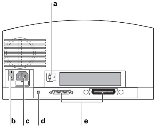
a SCSI address switch
b Power switch
c Power connector
d SCSI termination switch
e SCSI connectors (25, 50)
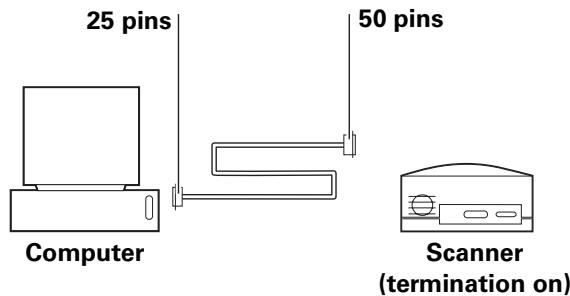
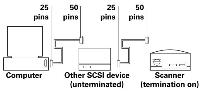
Connect the SCSI Cables
Place the scanner at the end of the SCSI chain or between the computer and other SCSI devices as shown in the following diagrams. Use the shortest possible cables.
Note: Turn the computer, scanner and all other SCSI devices off before connecting or disconnecting any cables. Do not connect the scanner to the parallel connector on your computer. Doing so could damage the scanner or computer.
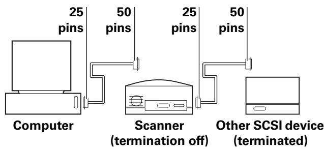
You may need additional cables or adapters to connect the scanner. Your cable must have a 50-pin Centronics M or DB-25 M connector at one end for attachment to the scanner, and the cable should be as short as possible. To determine the connector you need for attachment to your SCSI adapter, refer to instructions with the adapter.
Set Termination
Terminate the scanner and all other SCSI devices as shown in the appropriate cabling diagram to the left or on page 7. The last device in the SCSI chain must be terminated (or termination on), while all other devices must be unterminated (or termination off).
Set scanner termination with the termination switch (d on page 7). On = terminated, Off = unterminated.
Termination instructions for your other SCSI devices are provided with the devices.
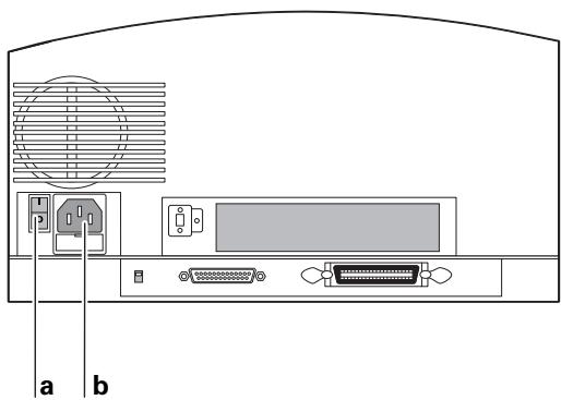
5 Connect the Scanner to AC Power and Turn On
1 Connect the power cord to the power connector (b).
natural_image
Back panel diagram showing electronic device ports and ventilation system (no text or labels)a Power switch
b Power connector
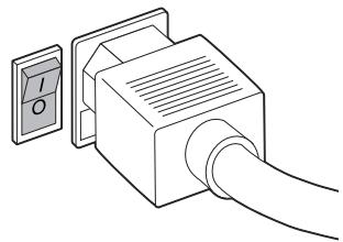
2 Turn the scanner power switch on.
natural_image
Diagram of a cable connector with a switch and power outlet (no text or symbols)3 Check the lights. The green light indicates power on. The yellow light blinks while the scanner initializes, and it remains steady when the scanner is ready. (The yellow light also blinks during scanning.)
4 Turn the computer on.
5 Wait for the system to install the scanner driver and display the normal desktop.
6 Loading the Film Carriers
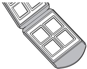
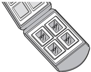
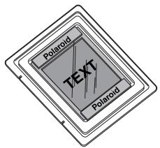
The Four-Slide Film Carrier
1 With the text facing up and the hinge at the top, open the carrier flat as shown.
natural_image
Illustration of a mobile phone with four square windows (no text or symbols)2 Place up to four mounted 35mm slides in the spaces provided. Be sure the slide mounts fit properly in the recessed areas. The images should be right-side up and right-reading as you do so. The emulsion side will face down.
natural_image
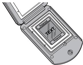
Illustration of a mobile phone case with four square buttons (no text or symbols visible)3 Close the carrier carefully.
The 4x5 Carrier (for 4x5 film)
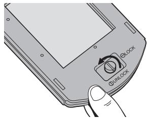
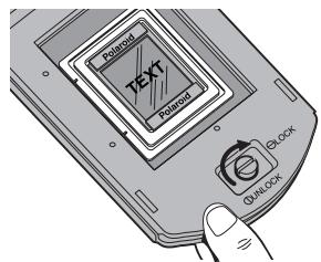
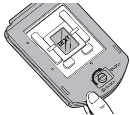
1 To unlock the carrier, squeeze the two halves of the carrier together at the bottom edge (near the locking knob) with one hand while turning the locking knob in either direction, until the slot in the knob points to UNLOCK.
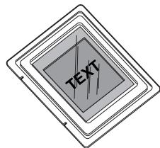
2 Open the carrier flat. Insert a 4x5 chrome or negative so that the left edge is against the positioning pins. Position the film so the image is right-reading and right-side up (emulsion-side down).
Note: The emulsion side is the dull side.
3 Close the carrier. Squeeze the carrier at the bottom edge and turn the knob to lock it.
The 120 Film Adapters
(for 2 1/4 x 21/4 and 2 1/4 x 2 3/4 in. film)
1 Open the 4x5 carrier as described previously.
2 Locate the appropriate adapter for your image. One is designed for 2 1/4 × 2 3/4 in. images, and one is for 2 1/4 × 2 in. square images.
Note: The frame of film must be cut from the film strip in order to be scanned.
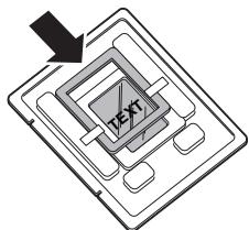
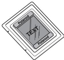
3 Orient the adapter so that the words THIS SIDE UP (on the adapter) face up, and the notches are at the left edge. Place the unmounted film over the opening, within the raised ridges of the adapter. Position the film so the image is right-reading and right-side up.
4 Secure the film with the two magnets provided, on the top and bottom edges. Be sure the magnets are also within the raised ridges.
5 Place the adapter in the 4x5 carrier, sliding the notches into the pins on the left edge. The film and magnets should be face up, as shown.
6 Close the carrier. Squeeze the carrier at the bottom edge and turn the knob to lock it.
The Single-35mm Carrier
1 Open the 4x5 carrier as described previously.
2 Locate the single-35mm adapter.
Note: You can use a negative, or a mounted or unmounted slide.
3 Orient the adapter so the metal tabs face up, and the notches are at the left edge. Slide the film into the channel, under the two metal tabs. Position the film so the image is right-reading and right-side up.
4 If the film is unmounted or the mount is thin, use the slide spacer provided. Position the slide spacer on top of the slide. The film should fit snugly into the adapter. (The spacer also ensures that the image will be at the correct distance from the scanning mechanism.)
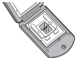
5 Place the adapter in the 4x5 carrier, sliding the notches into the pins on the left edge. The slide and tabs should be facing up.
natural_image
Diagram of a flip phone with internal circuitry and mounting base (no text or symbols)6 Close the carrier. Squeeze the carrier at the bottom edge and turn the knob to lock it.
natural_image
Illustration of a handheld electronic device with a central display and control knob (no text or symbols)7 Insert the Carrier into the Scanner
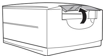
1 Open the carrier access door.
natural_image
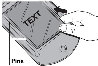
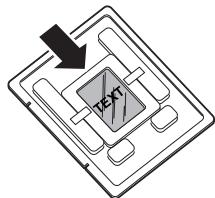
Line drawing of a mechanical component with a curved cutout and directional arrow (no text or symbols)2 Insert the carrier gently and firmly into the carrier slot as shown, until you feel it stop.
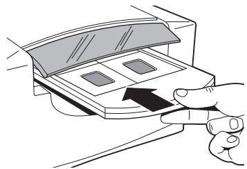
natural_image
Illustration of a hand inserting a card into a device (no text or symbols visible)3 Close the carrier access door. The scanner will not scan if the door is open.
Note: Do not open the carrier access door while a scan is in process; the scan will be interrupted. The scan will resume when the door is closed, but the quality of the scan may be reduced. Scan again with the door closed for best scanning quality.
4 Initiate the scan from your software. The software will prompt you when the scan is finished.
8 Preview an Image
1 Load the film or slide into the film carrier (as described previously).
2 Insert the carrier into the scanner (as described previously).
3 Start the PolaColor Insight program:
| Power Mac or PowerPC | Windows 95, 98 or NT |
| Double-click PolaColor Insight. | 1 Select Programs from the Start menu. |
| To start the Photoshop plug-in within another application, select Import from the application’s File menu and select PolaColor Insight. | 2 Point to Polaroid Pola-Color Insight, then select PolaColor Insight. |
4 Select the type of slide or negative you are scanning from the Input list on the Preview panel.
5 Select your monitor type from the Display list.
6 Type or select the number of the carrier frame you want to scan in the Frame Number box.
7 Click Preview.
The image appears on the Preview panel.
9 Enhance and Scan the Image
Follow the online user's guide instructions to enhance the image and perform a final scan.
To view the online PolaColor Insight User's Guide:
| Power Mac or PowerPC | Windows 95, 98 or NT |
| 1 Double-click PolaColor Insight, launching the PolaColor Insight program.2 Select PolaColor Insight Help from the Help menu. | 1 Select Programs from the Windows Start menu.2 Point to Polaroid Pola-Color Insight and select User's Guide. |
10 Remove the Carrier
1 When the scan is complete, open the door and remove the carrier. Remove the film and store it properly to protect it from dust and fingerprints.
2 Close the carrier access door. The door should be kept closed at all times to protect the mechanism from dust.
Installing a SCSI Host Adapter
The SprintScan 45 Ultra connects to a SCSI host adapter in your computer. Most Macintosh computers have a SCSI adapter built in, but most IBM PC compatible computers do not.
If you must install a SCSI adapter, turn the computer off and follow instructions provided by the adapter manufacturer. (The procedure usually includes software installation. If your PC uses the Windows NT operating system, log in as an administrator before installation.)
Limited Warranty
Polaroid Corporation warrants the SprintScan 45 Ultra scanner against defects in manufacture or workmanship for a period of one year from the date of purchase. To verify the warranty period, you should keep the invoice, sales receipt, or other proof of the purchase date.
Should this product or any component or accessory included with it, with the exception of software, prove to be defective at any time during the warranty period, Polaroid Corporation will, at its discretion, either replace or repair this item, without charge.
This warranty does not cover damage caused by accident, incorrect installation, unauthorized modification, and misuse or abuse. A charge will be made for repair of such damage.
This warranty excludes all consequential damages. Some jurisdictions do not allow the exclusion or limitation of consequential damages, so the foregoing exclusion may not apply to you.
Radio and Television Interference
FCC Notice (U.S.A.)
Note: This equipment has been tested and found to comply with the limits for a Class B digital device, pursuant to Part 15 of the FCC Rules. These limits are designed to provide reasonable protection against harmful interference in a residential installation. This equipment generates, uses, and can radiate radio frequency energy and, if not installed and used in accordance with the instructions, may cause harmful interference to radio communications. However, there is no guarantee that interference will not occur in a particular installation. If this equipment does cause harmful interference to radio or television reception, which can be determined by turning the equipment off and on, the user is encouraged to try to correct the interference by one or more of the following measures:
• Reorient/relocate the receiving antenna.
- Increase the separation between the equipment and receiver.
- Connect the equipment into an outlet on a circuit different from that to which the receiver is connected.
- Consult the dealer or an experienced radio/TV technician for help.
Note: A shielded interface cable with a ferrite core installed on the scanner connector end must be used with this equipment.
FCC Caution: To assure continued compliance, any changes or modifications not expressly approved by the party responsible for compliance could void the user's authority to operate the equipment.
Product: The Polaroid SprintScan 45 Ultra Scanner
Marketed by: Polaroid Corporation, Cambridge, MA 02139 U.S.A. Telephone: 1-800-432-5355
This device complies with Part 15 of the FCC Rules. Operation is subject to the following two considerations: (1) This device may not cause harmful interference, and (2) this device must accept any interference received, including interference that may cause undesired operation.
© 2000 Polaroid Corporation, Cambridge, MA 02139, U.S.A. All rights reserved.
“Polaroid”, “SprintScan”, and “PolaColor” are trademarks of Polaroid Corporation. All other product names may be trademarks of their respective owners. 111705B (PW-91396M-1)
Systemanforderungen
Macintosh-Systeme
natural_image
Back panel diagram showing electronic device ports and ventilation system (no text or labels)a Netzschalter
b Netzanschluss
natural_image
Diagram of a plug-in socket connected to a cable, showing internal components (no text or symbols)natural_image
Illustration of a folding tray with four square cutouts (no text or symbols)natural_image
Illustration of a mobile phone case with four compartments (no text or symbols visible)natural_image
Technical line drawing of a flip phone with internal circuitry (no text or symbols)natural_image
Illustration of a handheld electronic device with a circular button and a handle (no text or symbols)natural_image
Line drawing of a mechanical component with a curved cutout and directional arrow (no text or symbols)natural_image
Illustration of a hand inserting a card into a device (no text or symbols visible)natural_image
Back panel diagram showing electronic device rear panel with ports and connectors (no text or labels)a Interruptor
natural_image
Diagram of a cable connector with a switch and power outlet (no text or symbols)natural_image
Illustration of a folding mobile phone with four square windows (no text or symbols)natural_image
Illustration of a mobile phone case with four square buttons arranged in a grid (no text or symbols visible)natural_image
Diagram of a flip-flop with internal circuitry and mounting holes (no text or symbols)natural_image
Illustration of a handheld electronic device with a central display and control knob (no text or symbols)natural_image
Line drawing of a rectangular device with a curved arrow indicating rotation or movement (no text or symbols)natural_image
Illustration of a hand inserting a card into a device (no text or symbols visible)natural_image
Diagram of a computer monitor rear panel showing ports and ventilation grille (no text or labels)natural_image
Diagram of a connector with a power outlet and cable, no text or symbols presentnatural_image
Illustration of a folding tray with four square cutouts (no text or symbols)natural_image
Illustration of a mobile phone case with four compartments (no text or symbols visible)natural_image
Diagram of a flip phone with internal circuitry and mounting holes (no text or symbols)natural_image
Illustration of a handheld electronic device with a central display and control knob (no text or symbols)natural_image
Line drawing of a mechanical component with a curved cutout and directional arrow (no text or symbols)natural_image
Illustration of a hand inserting a card into a device (no text or symbols visible)natural_image
Diagram of a computer monitor rear panel showing ports and connectors (no text or labels)natural_image
Line drawing of a plug-in socket connected to a cable (no text or symbols)natural_image
Illustration of a folding tray with four square cutouts (no text or symbols)natural_image
Illustration of a mobile phone case with four compartments (no text or symbols visible)natural_image
Technical line drawing of a flip phone with internal circuitry (no text or symbols)natural_image
Illustration of a handheld electronic device with a circular button and a handle (no text or symbols)natural_image
Line drawing of a mechanical component with a curved cutout and directional arrow (no text or symbols)natural_image
Illustration of a hand inserting a card into a device (no text or symbols visible)Notifica FCC (U.S.A.)
This document provides corrections and updates for SprintScan 45 Ultra Installation Quickstart packaged with the scanner.
System Requirements (Page 3)
Macintosh Systems
- A Power Macintosh computer (includes Power Macintosh G3 and G4 computers) or compatible with a PowerPC processor, and 64 megabytes (MB) of RAM.
- A SCSI port.
• 400 MB of free disk space. - Scratch disk space equal to twice the final image file size plus 4 MB.
• Apple system software version 7.6 or later. - A video adapter and monitor capable of displaying thousands of colors, minimum. 24-bit color (16.7 million colors) is recommended for optimal display of scanned pictures.
Note: PolaColor Insight software runs on systems with video adapters and monitors with less color capability, but pictures displayed on the monitor may not be satisfactory.
PC Systems
- An IBM PC or compatible with a 300-MHz Pentium processor and 128 megabytes (MB) of RAM (RAM equal to twice the typical image file size recommended).
- Microsoft Windows 95, 98, 2000, Me or NT (version 4 or later) operating system.
• 400 MB of free disk space. - An ASPI-compliant SCSI adapter with the appropriate Windows drivers.
- A video adapter and monitor capable of displaying 24-bit color (16.7 million colors) is recommended for optimal display of scanned pictures.
Note: PolaColor Insight software runs on systems with video adapters and monitors with less color capability, but pictures displayed on the monitor may not be satisfactory.
1 Unpack the Box (Page 4)
The PolaColor Insight Software CD contains the following:
- PolaColor Insight software for Windows 95, 98, Me, 2000 and NT
- PolaColor Insight software for Power MAC and PowerPC systems
• Online user's guide
3 Install the Software (Page 5)
Step 3 for Power Mac or PowerPC (plug in installation) is no longer necessary. The Photoshop plug in for PolaColor Insight installs automatically during normal installation.
4 Connect the Scanner to the Computer (Page 6)
The SprintScan 45 Ultra scanner SCSI address is set to 6 at the factory. Do not change it unless another device is using that address. Do not use address switch setting 7, 8 or 9.
SCSI Termination Switch (Page 7)
The normal SCSI termination switch positions (d in the drawing on page 7) are up = on (terminated) and down = off (unterminated).
Scanners with serial numbers starting with the following characters, however, have the opposite configuration (up = off, down = on): D0, E0, F0, G0, H0. The serial number is on the bottom of the scanner.
The Four-Slide Film Carrier (Page 10)
The four-slide film carrier is compatible with thin plastic- and paper-mount 35mm slides. If you must force the carrier closed, however, do not use it. Instead, use the single 35mm adapter with the 4x5 carrier (page 12).
Glass-mount 35mm slides cannot be scanned with the four-slide film carrier. Use the single 35mm adapter with the 4x5 carrier.
The 120 Film Adapters (Page 11)
Steps 3 and 4 on pages 11 and 12 have changed to the following:
3 Orient the 120 film adapter with the correct side up and the notches (a) on the left. Place the unmounted film over the opening so the image is right-reading and the top of the image is at the top of the adapter.
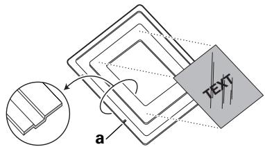
4 Secure the film by placing the two magnets provided on the top and bottom edges. The magnets must not extend over the depressed channel surrounding the film placement area.
Inserting the Carrier Into the Scanner (Page 14)
Step 2 has the following note added:
Note: When inserting the 4x5 film carrier, make sure the words "LOCK" and "UNLOCK" face upward. For the four-slide carrier, the words "THIS SIDE UP" face upward.