309008X51 - Riding mower MURRAY - Free user manual and instructions
Find the device manual for free 309008X51 MURRAY in PDF.

User questions about 309008X51 MURRAY
0 question about this device. Answer the ones you know or ask your own.
Ask a new question about this device
Download the instructions for your Riding mower in PDF format for free! Find your manual 309008X51 - MURRAY and take your electronic device back in hand. On this page are published all the documents necessary for the use of your device. 309008X51 by MURRAY.
USER MANUAL 309008X51 MURRAY
Model No. 309007x51A
Product Type
Mfg. No. Description
7800336 30” Murray CE Riding Mower
en Instruction Book - Riding mower
fr Manuel de l'utilisateur - Tondeuse autoportée
de Betriebsanleitung - Aufsitzmacher
it Istruzioni per l'uso - Trattore tagliaerba
nI Gebruikshandleiding - Zitmaaier
el Eyyxipidio odnywv xphons - Xoptokotikou yia eioxouev xeipoth
Da Driftsvejledning - Plænetraktor
no Bruksanvisning - Rider
sv Användarhandbok - Trädgårdtraktor
et Juhend - Traktorniiduki
hu Hasznalati Utmató - Onjáró fünyíró gép
Ru RykoBoDCTBO-KoHka c cndeHbem

CAUTION: Read and
follow all instructions.
Manual Part No. 1741751
Revision 00
Rev. Date 01/2008
TP 199-4843-00-RD-R
25

1

2

3
4
5

6
7
8

9
MAX±90N
MAX±150N

11

12

13

1

2

3

4

5

6

7

8

9

10

11

12

14

15

17x146

17x47
14x79

26

27
CONTENTS
INTERNATIONAL PICTORIALS 9
OWNER'S INFORMATION 10
SAFE OPERATION PRACTICES 10
ASSEMBLY 11
OPERATION 12
MAINTENANCE CHART 14
MAINTENANCE 14
TROUBLESHOOTING CHART 17
INTERNATIONAL PICTORIALS
IMPORTANT: The following pictorials are located on your unit or on literature supplied with the product. Before you operate the unit, learn and understand the purpose for each pictorial.
NOTE: Illustrations and pictorials begin on page 2.
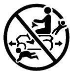
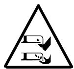
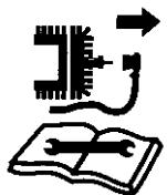
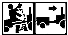
Safety Warning Pictorials (Figure 26)
1 WARNING
2 IMPORTANT: Read Owner's Manual Before Operating This Machine.
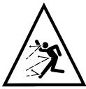
3 WARNING: Thrown Objects. Keep Bystanders Away. Read User Instructions Before Operating This Machine.
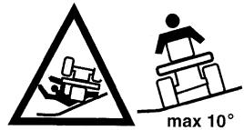
4 WARNING: Do Not Use This Machine On
Slopes Greater Than 10 Degrees.
5 DANGER: Keep People, Especially Children, Away From Unit.
6 DANGER: No Step.
7 DANGER: Keep Feet And Hands Away From Rotating Blade.
8 DANGER: Disconnect Spark Plug Wire Before Servicing Unit.
9 WARNING: Hot Surface.
10 WARNING: Use Caution When Connecting Or Disconnecting Accessories.
11 WARNING: Crushed Fingers.
12 IMPORTANT: Follow Instructions In Owner's Manual To Level The Deck.
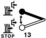
13 WARNING: Stay Clear Of Mower Blade As Long As Engine Is Running.
Control And Operating Pictorials (Figure 27)
1 Engine Start
2 Lights
3 Engine Run
4 Engine Stop
5 Engine Run
6 Brake
7 Parking Brake
8 Clutch
9 Slow
10 Fast
11 Choke
12 Oil
13 Blade Rotation Control
14 Raise
15 Fuel
Know your product: If you understand the unit and how the unit operates, you will get the best performance. As you read this manual, compare the illustrations to the unit. Learn the location and the function of the controls. To help prevent an accident, follow the operating instructions and the safety rules. Keep this manual for future reference.

WARNING: Look for this symbol to indicate important safety precautions. This symbol indicates: "Attention! Become Alert! Your Safety Is At Risk."
Responsibility Of The Owner

WARNING: This cutting machine is capable of amputating hands and feet and throwing objects. Failure
to observe the following safety instructions could result in serious injury or death to the operator or bystanders.
The responsibility of the owner is to follow the instructions below.
SAFE OPERATION PRACTICES
For Ride-On (Riding) Rotary Mower Machines
Training
- Read the instructions carefully. Be familiar with the controls and the proper use of the equipment.
- Never allow children or people unfamiliar with these instructions to use the mower. Local regulations may restrict the age of the operator.
- Never mow while people, especially children, or pets are nearby.
- Keep in mind that the operator or user is responsible for accidents or hazards occurring to other people or their property.
- Do not carry passengers.
- All drivers should seek and obtain professional and practical instruction. Such instruction should emphasize:
a. the need for care and concentration when working with ride-on machines;
b. control of a ride-on machine sliding on a slope will not be regained by the application of the brake. The main reasons for loss of control are:
insufficient wheel grip;
- being driven too fast;
- inadequate braking
the type of machine is unsuitable for its task;
- lack of awareness of the effect of ground conditions, especially slopes;
incorrect hitching and load distribution.
Preparation
- While mowing, always wear substantial footwear and long trousers. Do not operate the equipment when barefoot or wearing open sandals.
1741751
- Thoroughly inspect the area where the equipment is to be used and remove all objects which may be thrown by the machine.
3. WARNING - Petrol is highly flammable.
a. Store fuel in containers specifically designed for this purpose.
b. Refuel outdoors only and do not smoke while refuelling.
c. Add fuel before starting the engine. Never remove the cap of the fuel tank or add petrol while the engine is running or when the engine is hot.
d. If petrol is spilled, do not attempt to start the engine but move the machine away from the area of spillage and avoid creating any source of ignition until petrol vapours have dissipated.
e. Replace all fuel tanks and container caps securely.
- Replace faulty silencers.
- Before using, always visually inspect to see that the blades, blade bolts and cutter assembly are not worn or damaged. Replace worn or damaged blades and bolts in sets to preserve balance.
- On multi-blade machines, take care as rotating one blade can cause other blades to rotate.
Operation
- Do not operate the engine in a confined space where dangerous carbon monoxide fumes can collect.
- Mow only in daylight or in good artificial light.
- Before attempting to start the engine, disengage all blade attachment clutches and shift into neutral.
- Do not use on slopes of more than 10 degrees.
- Remember there is no such thing as a "safe" slope. Travel on grass slopes requires particular care. To guard against overturning:
a. do not stop or start suddenly when going up or downhill;
b. engage clutch slowly, always keep machine in gear, especially when travelling downhill;
c. machine speeds should be kept low on slopes and during tight turns;
d. stay alert for humps and hollows and other hidden hazards;
e. never mow across the face of the slope, unless the mower is designed for this purpose.
- Use care when pulling loads or using heavy equipment.
a. Use only approved drawbar hitch points.
b. Limit loads to those you can safely control.
c. Do not turn sharply. Use care when reversing.
d. Use counterweight(s) or wheel weights when suggested in the Instruction Book.
- Watch out for traffic when crossing or near roadways.
- Stop the blades rotating before crossing surfaces other than grass.
- When using any attachments, never direct discharge of material toward bystanders
nor allow anyone near the machine while in operation.
- Never operate the mower with defective guards or shields, or without safety protective devices in place.
-
Do not change the engine governor settings or overspeed the engine. Operating an engine at excessive speed may increase the hazard of personal injury.
-
Before leaving the operator's position
a. disengage the power take-off and lower the attachments;
b. change into neutral and set the parking brake;
c. stop the engine and remove the key.
- Disengage drive to attachments, stop the engine, and disconnect the spark plug wire(s) or remove the ignition key
a. before cleaning blockages or unclogging chute;
b. before checking, cleaning or working on the mower;
c. after striking a foreign object. Inspect the mower for damage and make repairs before restarting and operating the equipment;
d. if the machine starts to vibrate abnormally (check immediately).
- Disengage drive to attachments when transporting or not in use.
- Stop the engine and disengage drive to attachment
a. before refuelling;
b. before removing the grass catcher;
c. before making height adjustment unless adjustment can be made from the operator's position.
- Reduce the throttle setting during engine run-out and, if the engine is provided with a shut-off valve, turn the fuel off at the conclusion of mowing.
- Before and when backing, look behind and down for small children.
- Use extra care when approaching blind corners, shrubs, trees or other objects that may obscure vision.
Maintenance and Storage
- On multi-blade machines, take care as rotating one blade can cause other blades to rotate.
- When machine is to be parked, stored or left unattended, lower the cutting means unless a positive mechanical lock is used.
- Keep all nuts, bolts, and screws tight to be sure the equipment is in safe working condition.
- Never store the equipment with petrol in the tank inside a building where fumes may reach an open flame or spark.
- Allow the engine to cool before storing in any enclosure.
- To reduce the fire hazard, keep the engine, silencer, battery compartment and petrol storage area free of grass, leaves, or excessive grease.
- Check the grass catcher frequently for wear or deterioration.
- Replace worn or damaged parts for safety.
- If the fuel tank has to be drained, this should be done outdoors.
All fasteners are in the parts bag. Do not discard any parts or material until the unit is assembled.

WARNING: Before doing any assembly or maintenance to the mower, remove the wire from the
spark plug.
NOTE: In this instruction book, left and right describe the location of a part with the operator on the seat.
NOTE: Illustrations and pictorials begin on page 2.
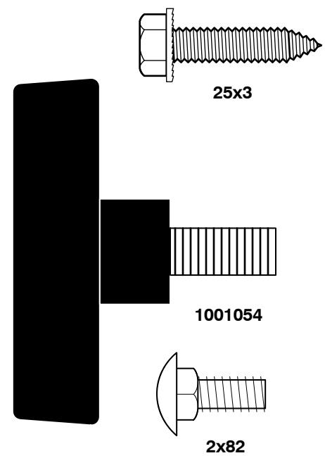
NOTE: To assemble the following loose parts, use the fasteners shown at full size in Figure 28.
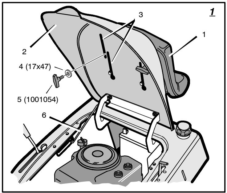
How To Install The Seat (Figure 1)
- Carefully remove the plastic bag from the seat (1).
- Raise the seat support (2) and secure in the UP position with the seat support rod (6).
- Align the holes in the seat (1) to the holes in the seat support (2). Fasten the seat (1) to the seat support (2) with the fasteners (4) and (5).
- Check the operating position of the seat (1). If the seat (1) needs to be adjusted, loosen the two wing bolts (5). Slide the seat (1) forward or backward along the seat adjusting holes (3). Tighten the wing bolts (5).
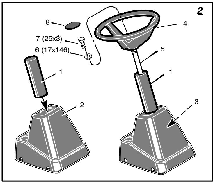
How To Assemble The Steering Wheel (Figure 2)
- Make sure the front wheels point forward.
- Slide the tube (1) into the console (2). Make sure the end of the tube (1) fits over the steering bushing (3).
- Attach the steering wheel (4) to the steering post (5) with screw (7) and washer (6).
- Slide the steering wheel (4) and steering post (5) into the tube (1) and console (2). Push on the steering wheel (4). The steering post (5) will lock onto the pinion gear. Pull on the steering wheel (4). Make sure that the steering post (5) is locked in place.
- Some models have an optional insert (8) in the parts bag. Attach the insert (8) to the centre of the steering wheel (4).
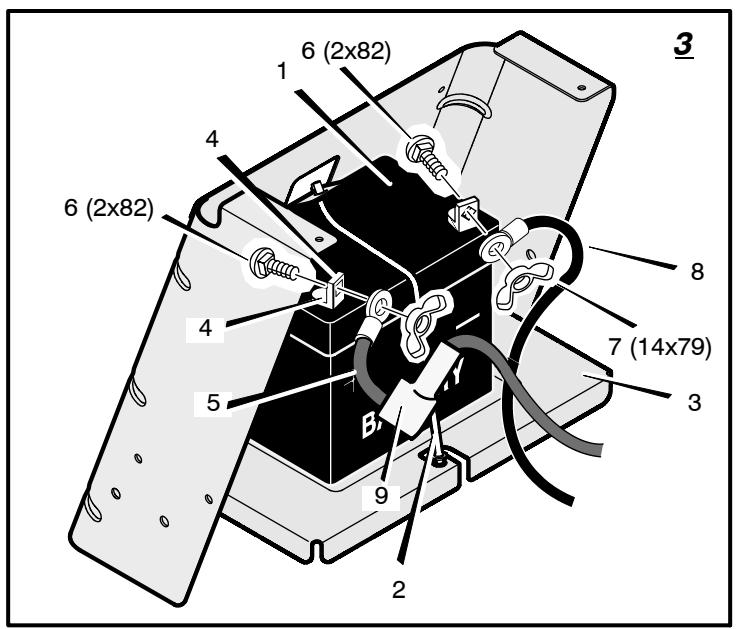
Maintenance Free Battery (Figure 3)
IMPORTANT: Before you attach the battery cables to the battery, check the battery date. The battery date tells if the battery must be charged.
- Raise the seat support and secure in the UP position with the seat support rod.
- Check the top of the battery (1) for the location of the battery date.
- If the battery (1) is put into service before the battery date, the battery cables can be attached without charging the battery (1). See "How To Install The Battery Cables".
- If the battery (1) is put into service after the battery date, the battery (1) must be charged. See "How To Charge The Maintenance Free Battery".
How To Charge The Battery (Figure 3)

WARNING: When you charge the battery, do not smoke. Keep the battery away from any sparks. The
fumes from the battery acid can cause an explosion.
- To disconnect the battery retainer (2) from the battery tray (3), push in on the lower end of the battery retainer (2).
- Remove the battery (1) from the right side of the unit.
- Remove the protective cap from the battery terminal.
- Use a 12 volt battery charger to charge the battery (1). Charge at a rate of 6 amperes for one hour. If you do not have a battery charger, have an authorized service centre charge the battery.
- Install the battery (1) and secure with the battery retainer (2). Make sure the positive (+) terminal (4) is on the right side.
How To Install The Battery Cables (Figure 3)

WARNING: To prevent sparks, fasten the red cable to the positive (+) terminal before you connect the black
cable.
- Remove the protective cap from the battery terminal.
- Fasten the red cable (5) and terminal cover (9) to the positive (+) terminal (4) with the fasteners (6) and (7).
- Fasten the black cable 8 to the negative (-) terminal with the fasteners (6) and (7).
Check The Tyres
Check the air pressure in the tyres. Tyres with too much air pressure will cause the unit to ride rough. Also, the wrong air pressure will keep the mower housing from cutting level. The correct air pressure is: Front Tyres 0,97 BAR (14 PSI), Rear Tyres 0,69 BAR (10 PSI). The tyres were over inflated for shipment.
Check The Level Of The Mower Housing
Make sure the level of cut is still correct. After you mow a short distance, look at the area that was cut. If the mower housing does not cut level, see the instructions on "How To Level The Mower Housing" in the Maintenance section of this instruction book.
How To Prepare The Engine
NOTE: The engine was shipped from the factory filled with oil. Check the level of the oil. Add oil as needed.
See the engine manufacturer's instructions for the type of petrol and oil to use. Before you use the unit, read the information on safety, operation, maintenance, and storage.

WARNING: Follow the engine manufacturer's instructions for the type of petrol and oil to use. Always use a
safety petrol container. Do not smoke when adding petrol to the engine. When inside an enclosure, do not fill with petrol. Before you add petrol, stop the engine. Let the engine cool for several minutes.
Important! Before You Start Mowing
Check the engine oil.
Fill the fuel tank with petrol.
Check the level of the mower housing.
Check the air pressure of the tyres.
- Attach the battery cables.
Final Assembly
- Check all fasteners. Make sure all fasteners are properly installed and are tight.
- Check installation. Make sure all parts are correctly installed.

WARNING: Make sure that the grass bagger is properly assembled and correctly installed.
The Grass Bagger must only be used when fully assembled and correctly installed.
NOTE: Illustrations and pictorials begin on page 2.
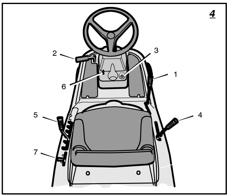
Location Of Controls (Figure 4)
Blade Rotation Control (1): Use the blade rotation control to start and stop the rotation of the blade.
Clutch / Brake Pedal (2): The pedal has two functions. The first function is a clutch. The second function is a brake.
Ignition Switch (3): Use the ignition switch to start and stop the engine.
Shift Lever (4): Use the shift lever to change the speed of the unit.
Lift Lever (5): Use the lift lever to change the height of cut.
Parking Brake Lever (6): Use the parking brake lever to engage the brake when you leave the unit.
Throttle Control Lever (7): Use the throttle control lever to increase or decrease the speed of the engine.
Attachments
This unit can use many different attachments. This unit can pull attachments like a lawn sweeper, a lawn aerator, or a hopper spreader. This unit can not use attachments that engage the ground like a plough, a disk harrow, or a cultivator.
For trailer and pull-behind attachments, the maximum weight is 90kg (200 lbs.).
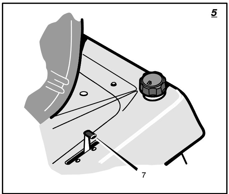
How To Use The Throttle Control (Figure 4 and Figure 5)
Use the throttle/choke control (7) to increase or decrease the speed of the engine.
- Move the throttle/choke control (7) completely forward to the CHoke position to start a cold engine.
- The FAST position is marked with a detent. For normal operation and when using a grass bagger, move the throttle control to the FAST position. For maximum charging of the battery and for a cooler running engine, operate the engine in the FAST position.
- The engine governor is set at the factory for maximum performance. Do not adjust the governor to increase the speed of the engine.
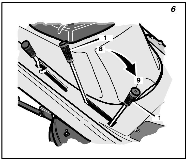
How To Use The Blade Rotation Control (Figure 4 and Figure 6)
Use the blade rotation control (1) to engage the blade(s).
- Before you start the engine, make sure the blade rotation control (1) is in the DISENGAGE position (8).
- To rotate the blade, move the blade rotation control (1) forward to lock the blade in the ENGAGE position (9).
- To stop the blade, move the blade rotation control (1) to the DISENGAGE position (8). Before you leave the operator's position, make sure the blade(s) has stopped rotating.
- Before you ride the unit across a sidewalk or a road, move the blade rotation control (1) to the DISENGAGE position.
1741751

WARNING: Always keep your hands and feet away from the blade, deflector opening, and the housing when the engine runs.
How To Use The Shift Lever
To change the forward speed or the direction of the unit, follow the steps below.
CAUTION: Before you move the shift lever, completely push the clutch/brake pedal (2) forward to stop the unit. If the unit is not stopped, the gearbox can be damaged.
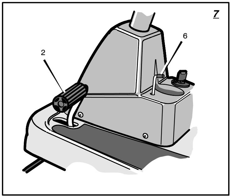
- (Figure 7) Completely push the clutch/ brake pedal (2) forward to stop the unit. Keep your foot on the pedal.
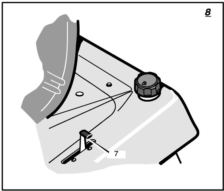
- (Figure 8) Move the throttle control lever (7) to the SLOW position.
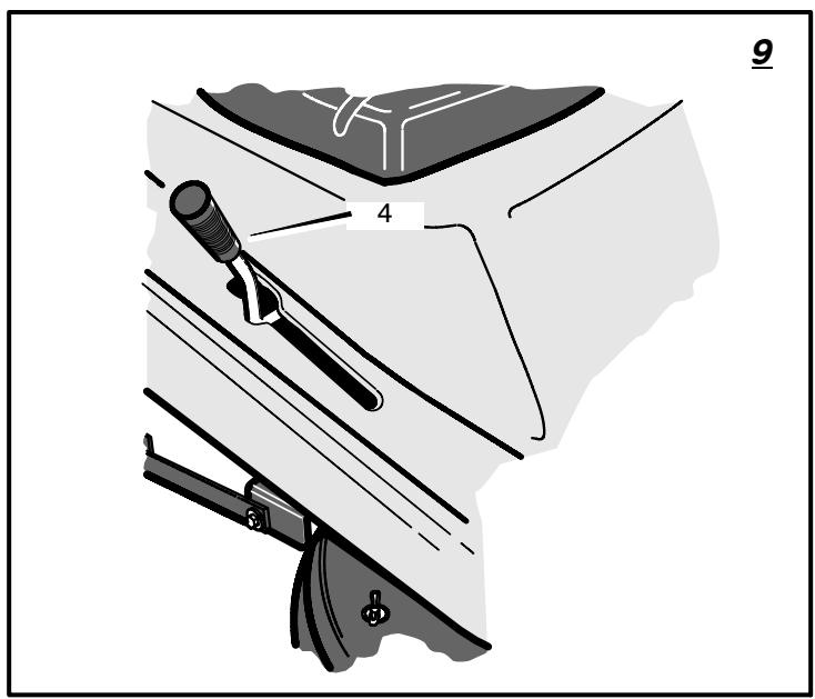
- (Figure 9) To go forward, move the shift lever (4) to a forward speed setting. To go backward, move the shift lever (4) to reverse.
- (Figure 7) Slowly release the clutch/brake pedal (2). Do not keep your foot on the pedal.
- (Figure 8) Move the throttle control (7) to the FAST position.
How To Use The Parking Brake (Figure 7)
- Completely push the clutch/brake pedal (2) forward.
- Lift the parking brake lever (6).
- Remove your foot from the clutch/brake pedal (2) and then release the parking brake lever (6). Make sure the parking brake will hold the unit.
- To release the parking brake (6), completely push the clutch/brake pedal (2) forward. The parking brake will automatically release.

WARNING: Before you leave the operator's position, move the shift lever to the neutral (N) position. Set
the parking brake. Move the blade rotation control to the DISENGAGE position. Stop the engine and remove the ignition key.
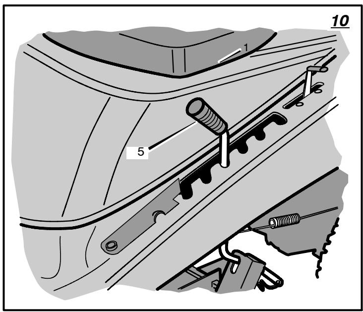
How To Change The Cutting Height (Figure 10)
To change the cutting height, raise or lower the lift lever (5) as follows.
- Move the lift lever (5) forward to lower the mower housing and back to raise the mower housing.
- When you ride on a sidewalk or road, move the lift lever (5) to the highest position and move the blade rotation control to the DIS-ENGAGE position.
How To Stop The Unit (Figure 4)
- Completely push the clutch/brake pedal (2) forward to stop the unit. Keep your foot on the pedal.
- Move the blade rotation control (1) to the DISENGAGE position.
- Move the shift lever (4) to the NEUTRAL position.
- Set the parking brake (6).

WARNING: Make sure the parking brake will hold the unit.
- Move the throttle control (7) to the SLOW position.
- To stop the engine, turn the ignition key (3) to the OFF position. Remove the key.
How To Transport The Unit
To transport the unit, follow the steps below.
- Move the blade rotation control to the DIS-ENGAGE position.
- Raise the lift lever to the highest position.
- Move the throttle control to a position between SLOW and FAST.
- To go faster, move the shift lever to a faster speed.
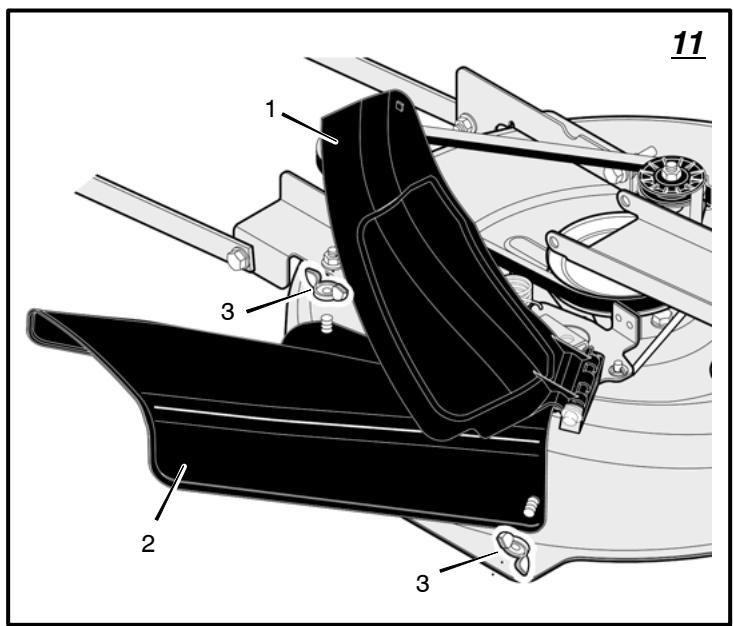
How To Install The Side Discharge Attachment (Figure 11)

WARNING: To prevent the engine from starting, disconnect the wire from the spark plug.
Make sure the attachment clutchblade rotation control is in the DISENGAGE position.
The mulcher cover (1) lets you mulch the grass for a clean, fine cut. To discharge the grass out the side, install the side discharge attachment (2) as follows.
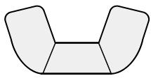
- Remove the two wingnuts (3) that secure the mulcher cover (1).
- Lift the mulcher cover (1). Mount the side discharge attachment (2) onto the same bolts that secured the mulcher cover (1).
- Secure the side discharge attachment (2) with the wingnuts (3).
- To mulch, remove the side discharge attachment (2) and mount the mulcher cover (1) to the mower housing with the wingnuts (3).
How To Operate With The Mower Housing

WARNING: The mulch cover is a safety device. Do not remove the mulch cover. The deflector is the discharged material toward round. Always keep the deflector down position. If the deflector is used, replace the deflector with original equipment part from an audited service center.
IMPORTANT: When you operate with the mower housing, always operate with the throttle control in the FAST position.
- Start the engine.
- Move the lift lever to a height of cut position. In high or thick grass, cut the grass in the highest position first and then lower the mower housing to a lower position.
- Move the throttle control to the SLOW position.
- Slowly move the blade rotation control to the ENGAGE position.
- Push the clutch/brake pedal completely forward.
- Move the shift lever to one of the speed settings.
NOTE: When you mow in heavy grass or mow with a bagger, put the shift lever in the slowest speed.
- Slowly release the clutch/brake pedal.
- Move the throttle control to the FAST position. If you need to go faster or slower, stop the unit and move the shift lever to another speed setting.
- Make sure the level of cut is still correct. After you mow a short distance, look at the area that was cut. If the mower housing does not cut level, see the instructions on "How To Level The Mower Housing" in the Maintenance section.

WARNING: For better control of the unit, select a safe speed.
How To Operate On Hills

WARNING: Do not ride up or down slopes that are too steep to back straight up. Never ride the unit
across a slope.
- Before you ride up or down a hill, move the shift lever to the slowest speed.
- Do not stop or change speed settings on a hill. If you must stop, quickly push the clutch/ brake pedal forward and set the parking brake.
- To start again, make sure the shift lever is in the slowest speed. Move the throttle control to the SLOW position. Slowly release the pedal.
- If you must stop or start on a hill, always have enough space for the unit to roll when you release the brake and engage the clutch.
- Be very careful when you change directions on a hill. When on a slope or in a turn on a hill, move the throttle control to the SLOW position to help prevent an accident.
Before Starting The Engine
Check the oil
NOTE: The engine was shipped from the factory filled with oil. Check the level of the oil. Add oil as needed. See the engine manufacturer's instructions for the type of petrol and oil to use.
- Make sure the unit is level.
NOTE: Do not check the level of the oil while the engine runs.
- Check the oil. Follow the procedure in the engine manufacturer's instructions.
- If necessary, add oil until the oil reaches the FULL mark on the dipstick. The quantity of oil needed from ADD to FULL is shown on the dipstick. Do not add too much oil.
Add Petrol

WARNING: Always use a safety petrol container. Do not smoke when adding petrol to the fuel tank.
Do not add petrol when you are inside an enclosure. Before you add petrol, stop the engine and let the engine cool for several minutes.
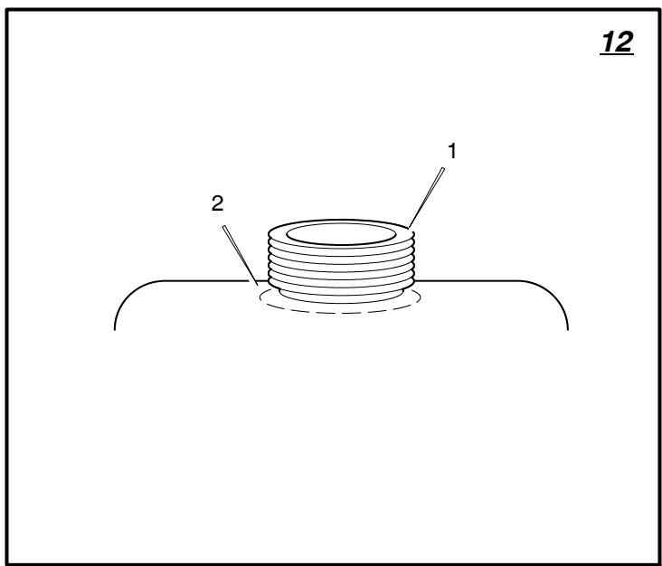
(Figure 12) Fill the fuel tank (1) to the FULL (2) position with regular unleaded petrol. Do not use premium unleaded petrol. Make sure the petrol is fresh and clean. Leaded petrol will increase deposits and shorten the life of the valves.
How To Start The Engine

WARNING: The electrical system has an operator presence system that includes a sensor switch for
the seat. These components tell the electrical system if the operator is sitting on the seat. This system will stop the engine when the operator leaves the seat. For your protection, always make sure this system operates correctly.
NOTE: The engine will not start unless you depress the clutch/brake pedal and move the blade rotation control to the DISENGAGE position.
- Push the clutch/brake brake pedal completely forward. Keep your foot on the pedal.
- Move the shift lever to the neutral (N) position.
- Make sure the blade rotation control is in the DISENGAGE position.
- Move the throttle control completely forward to the CHOKE or FAST position. Some models have a separate choke knob. Pull the choke knob to the full CHOKE position.
- Turn the ignition key to the START position.
NOTE: If the engine does not start after four or five tries, move the throttle control to the FAST position. Again try to start the engine. If the engine will not start, see the TROUBLE SHOOTING CHART.
- Slowly move the throttle control to the SLOW position.
- To start a hot engine, move the throttle control to a position between FAST and SLOW.
Mowing And Bagging Tips
- For a lawn to look better, check the cutting level of the mower housing. See "How To Level The Mower Housing" in the Maintenance section.
- For the mower housing to cut level, make sure the tyres have the correct amount of air pressure.
-
Every time you use the unit, check the blade. If the blade is bent or damaged, immediately replace the blade. Also, make sure the nut for the blade is tight.
-
Keep the blade(s) sharpened. Worn blades will cause the ends of the grass to turn brown.
- Do not cut or bag grass that is wet. Wet grass will not discharge correctly. Let the grass dry before cutting.
- Use the left side of the mower housing to trim near an object.
- Discharge the cut grass onto the mowed area. The result is a more even discharge of cut grass.
- When you mow large areas, start by turning to the right so that the cut grass will discharge away from shrubs, fences, driveways, etc. After one or two rounds, mow in the opposite direction making left turns until finished.
- If the grass is very high, cut two times to decrease the load on the engine. First cut with the mower housing in the highest position and then lower the mower housing for the second cut.
- For better engine performance and an even discharge of the cut grass, always operate the engine with the throttle in FAST position.
- When you use a dagger, operate the engine with the throttle in FAST position and the shift lever in first or second gear.
- For better cutting performance and a quality cut, mow with the shift lever in one of the slower speeds.
- After each use, clean the bottom and top of the mower housing for better performance. Also, a clean mower housing will help prevent a fire.
Mulching Tips
When you use a mulcher attachment, the grass is cut into very small pieces. These small pieces will quickly break down. Because the nutrients are returned to the soil, the lawn will need less fertilizer. To correctly mulch the grass, follow the steps below.
- Set the throttle in the FAST position. Operate the mower at a slower ground speed. If ground speed is too fast, the grass will not have an even cut.
- Keep a sharp edge on the blade. A blade that is not sharp will cause the ends of the grass to become brown.
- Make sure the grass is dry. Wet grass is difficult to cut.
- Set the height of the mower housing so that only the top third of the grass is cut. If the grass is too high, set the height of the mower housing to the maximum height. Then, lower the mower housing for the second cut. Also, instead of using the full width of the mower housing, mulch at half the width.
- Clean the bottom of the mower housing. Grass and other debris can keep the mower from working correctly.
- If the grass grows fast, mulch more often.
- If an area needs improvement, mulch a second time.
MAINTENANCE CHART
| FREQUENCY | MAINTENANCE REQUIRED | COMMENTS |
| Daily or before each use | Maintenance engine. | Refer to the Engine Owner's Manual. |
| Examine blade(s). | Check for cracks, wear, and excessive damage. | |
| Remove debris from unit and mowing area. | ||
| Examine all rotating and sliding parts. | ||
| Check tire inflation. | Refer to the Maintenance section. | |
| Verify that the mower housing is level. | Refer to the Maintenance section. | |
| Examine V-belts. | Check for cracks, wear, and excessive damage. | |
| Check brake operation. | Refer to the Operation and Maintenance sections. | |
| After completion of first 5 hours | Change oil. | Refer to the Engine Owner's Manual. |
| After 25 hours | Maintenance engine. | Refer to the Engine Owner's Manual. |
| Remove, examine, sharpen, and balance blade(s). | Refer to Maintenance section. | |
| Check adjustments: a. Blade Rotation Control b. Brake c. Clutch d. Steering | Refer to Maintenance section. | |
| Lubricate chassis and mower housing. | Refer to Where to Lubricate instructions. | |
| Check the muffler: a. Torque b. For wear or burn out c. Condition of spark arrester, (if applicable). | Refer to Maintenance section. | |
| Before storage of 30 days or more | Prepare engine for storage. | Refer to the Engine Owner's Manual. |
| Drain fuel system. | Refer to warnings in the Owner's Manual. | |
| Add fuel stabilizer. | Refer to the Engine Owner's Manual. | |
| Prepare battery for storage: a. Remove from unit. b. Fully charge. c. Move to cool dry place. |
MAINTENANCE
NOTE: Illustrations and pictorials begin on page 2.
General Recommendations
- The owner's responsibility is to maintain this product. This will extend the life of the product and is also necessary to maintain warranty coverage.
- Check the spark plug, drive brake, lubricate the unit, and clean the air filter once a year.
- Check the fasteners. Make sure all fasteners are tight.
- Follow the Maintenance section to keep the unit in good operating condition.

WARNING: Before you make an inspection, adjustment, or repair to the unit, disconnect the wire to the
spark plug. Remove the wire from the spark plug to prevent the engine from starting by accident.
NOTE: Torque is measured in foot pounds (metric Nm). This measurement describes how tight a nut or bolt must be. The torque is measured with a torque wrench.
1741751
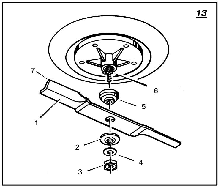
Inspect Blade (Figure 13)

WARNING: Before you inspect or remove the blade, disconnect the wire to the spark plug. If the blade
hits an object, stop the engine. Check the unit for damage. The blade has sharp edges. When you hold the blade, use gloves or cloth material to protect your hands.
If you keep the blade (1) sharp and inspect the blade for damage, the blade will cut better and be more safe to operate. Frequently check the blade for excessive wear, cracks, or other damage. Frequently check the nut (3) that holds the blade (1). Keep the nut (3) tight. If the blade hits an object, stop the engine. Disconnect the wire to the spark plug. See if the blade is bent or damaged. Check the blade adapter (5) for damage. Before you operate the unit, replace damaged parts with original equipment parts. See the authorized service centre in your area. Every three years, have an authorized service person inspect the blade or replace the old blade with an original equipment part.
How To Remove And Install The Blade (Figure 13)
- Remove the mower housing. See the instructions on "How To Remove The Mower Housing".
-
Use a piece of wood to keep the blade from rotating.
-
Remove the nut (3) that holds the blade (1).
- Check the blade (1) and the blade adapter (5) according to the instructions for "Inspect Blade". Replace a badly worn or damaged blade with an original equipment blade. See an authorized service centre in your area.
- Clean the top and bottom of the mower housing. Remove all the grass and debris.
- Mount the blade (1) and blade adapter (5) on the mandrel (6).
- Mount the blade (1) so that the hi-lift edges (7) are up. If the blade is upside down, the blade will not cut correctly and can cause an accident.
- Fasten the blade (1) with the original washers and nut (3). Make sure the outside rim of the Belleville washer (2) is against the blade (1).

WARNING: Always keep the nut (3) tight that holds the blade (1). A loose nut or blade can cause an
accident.
- Tighten the nut (3) that holds the blade (1) to a torque of 30 foot pounds (41,5Nm)
- Install the mower housing. See "How To Remove The Mower Housing".
How To Check The Blade Rotation Control

WARNING: To prevent an injury, the blade rotation control must operate correctly.
In normal usage, the blade rotation control will not require an adjustment. However, if the cut
ting performance decreases or the quality of cut is poor, make the following changes.
- When you mow, make sure the throttle control is in the FAST position.
- (Figure 6) Move the blade rotation control (1) to the DISENGAGE position (8).
- Stop the engine. Disconnect the wire from the spark plug.
- Check the blade(s). Keep a sharp edge on the blade(s). A blade that is not sharp will cause the tips of the grass to become brown.
- If the quality of cut has not improved, replace the mower drive belt. See "How To Replace The Mower Drive Belt". If the replacing the belt does not correct the problem, take the unit to an authorized service centre.
- Move the blade rotation control (1) to the DISENGAGE position (8). Stop the engine. Disconnect the wire from the spark plug.
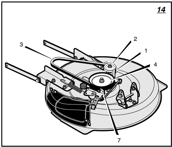
- (Figure 14) Check the operation of the blade brake. Rotate the pulley with your hand. Make sure that the brake pad (7) is pressed tightly against the pulley.

WARNING: If the brake pad (7) does not press tightly against the pulley, take the unit to an authorized ser
vice centre.
- (Figure 6) Move the blade rotation control (1) to the ENGAGE position (9).
- (Figure 14) Check the pads for the blade brake (7). If the pads are excessively worn or damaged, replace the brake pad assemblies. Correct replacement parts and assistance are available from an authorized service centre.
- Attach the wire to the spark plug. Mow for a short distance and again check the operation of the blade rotation control.
- When you move the blade rotation control to the DISENGAGE position, all movement will stop within five seconds. If there is movement of the belt or the blades continue to rotate, engage and disengage the blade rotation control five times to remove any excess rubber from a new mower drive belt. If you need assistance, take the unit to an authorized service centre.
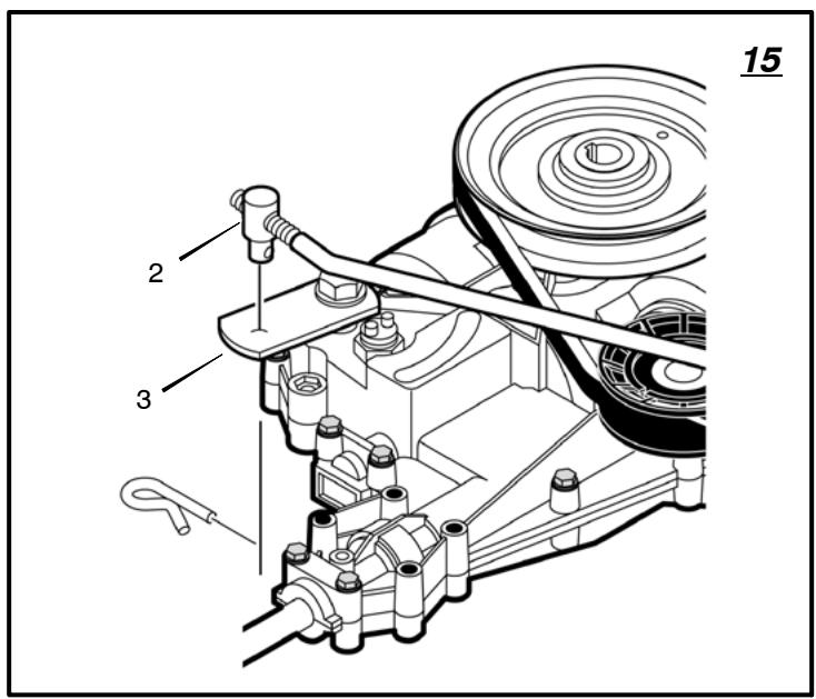
How To Adjust The Shift Lever (Figure 15)
If the NEUTRAL position on the shift lever does not match neutral on the gearbox, adjust the shift lever as follows.
- Stop the engine.
- Disconnect the adjuster nut (2) from the shifter yoke (3).
- Make sure the shift lever is in the NEUTRAL position.
- Push the unit forward. Make sure the gearbox is in neutral.
- To align the adjuster nut (2) with the hole in the shifter yoke (3), turn the adjuster nut (2).
- Connect the adjuster nut (2) to the shifter yoke (3).
- Make sure the NEUTRAL position on the shift lever matches neutral on the gearbox. 1741751
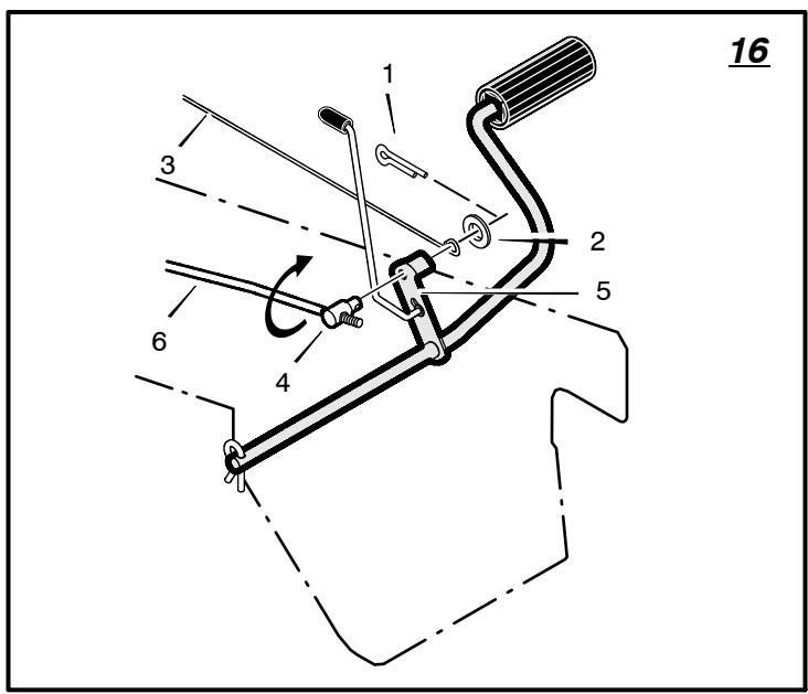
How To Check And Adjust The Clutch (Figure 16)
If the motion drive belt is loose, the clutch will slip when; going up a hill, pulling a heavy load, or the unit will not move forward. Adjust the clutch as follows.

WARNING: Before you make an inspection, adjustment, or repair to the unit, disconnect the wire to the
spark plug. Remove the wire from the spark plug to prevent the engine from starting by accident.
- Check the routing of the motion drive belt. Make sure the belt is installed correctly and is inside all the belt guides.
- Remove the cotter pin (1), washer (2), and brake spring (3) from the adjustable nut (4).
- Disconnect the adjustable nut (4) from the brake lever assembly (5).
- Align the hole in the brake lever (5) with the rear of the slot in the frame.
- Push the clutch rod (6) toward the rear. Turn the adjustable nut (4) until the nut will fit through the hole in the brake lever (5).
- Assemble the adjustable nut (4) to the brake lever (5) and to the brake spring (3). Fasten with the washer (2) and cotter pin (1).
- If the belt still slips after the clutch has been adjusted, then the motion drive belt is worn or damaged and must be replaced. See "How To Replace The Motion Drive Belt".
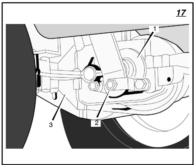
How To Check And Adjust The Drive Brake (Figure 17)
Completely push the clutch/brake pedal forward. Set the parking brake. Move the shift lever to the neutral (N) position. Push the unit. If the rear wheels rotate, adjust or replace the brake pads. Adjust the drive brake (1) as follows.
- The location of the drive brake (1) is on the left side of the gearbox (3).
- Make sure the parking brake is set and the shift lever is in neutral (N). Turn the hex nut (2) in a clockwise direction until the rear wheels do not turn when the unit is pushed forward.
- Release the parking brake and push the unit. If the unit does not roll, turn the hex nut (2) in a counter-clockwise direction until the unit rolls.
- Set the parking brake. Push the unit. If the rear wheels do not turn, the drive brake (1) is correctly adjusted. Release the parking brake.

WARNING: If you cannot correctly adjust the drive brake, replace the brake pads. Correct replacement
parts and assistance are available from an authorized service centre.
How To Remove The Battery (Figure 3)
To charge or clean the battery (1), remove the battery (1) from the unit as follows.

WARNING: To prevent sparks, disconnect the black battery cable (8) from the negative (-) terminal beu disconnect the red cable (5).

WARNING: The battery contains sulphuric acid which is harmful to the skin, eyes and clothing. If the
acid gets on the body or clothing, wash with water.
- Disconnect the black cable (8) from the negative (-) terminal.
- Disconnect the red cable (5) from the positive (+) terminal (4).
- To disconnect the battery retainer (2) from the battery tray (3), push in on the lower end of the battery retainer (2).
- Remove the battery (1) from the right side of the unit.
How To Charge The Battery (Figure 3)

WARNING: When you charge the battery, do not smoke. Keep the battery away from any sparks. The
fumes from the battery acid can cause an explosion.
- Before you charge the battery (1), remove the battery (1).
- To charge the battery (1), use a 12 volt battery charger. Charge at a rate of 6 amperes for 1 hour.
- Install the battery (1).

WARNING: To prevent sparks, fasten the red cable to the positive (+) terminal before you connect the cable.
- Fasten the red cable (5) to the positive (+) terminal (4) with the fasteners as shown.
- Fasten the black cable (8) to the negative (-) terminal with the fasteners as shown.
- Connect the battery retainer (2) to the battery tray (3).
How To Level The Mower Housing
If the mower housing is level, the blade will cut easier and the lawn will look better.

WARNING: Before you make an inspection, adjustment, or repair to the unit, disconnect the wire to the
spark plug. Remove the spark plug wire to prevent the engine from starting by accident
- Make sure the unit is on a hard flat surface.
-
Check the air pressure in the tyres. If the air pressure is incorrect, the mower housing will not cut level. Make sure the tyres are inflated to: Front Tyres 0,97 BAR (14 PSI), Rear Tyres 0,69 BAR (10 PSI).
-
Open the cover (5).
-
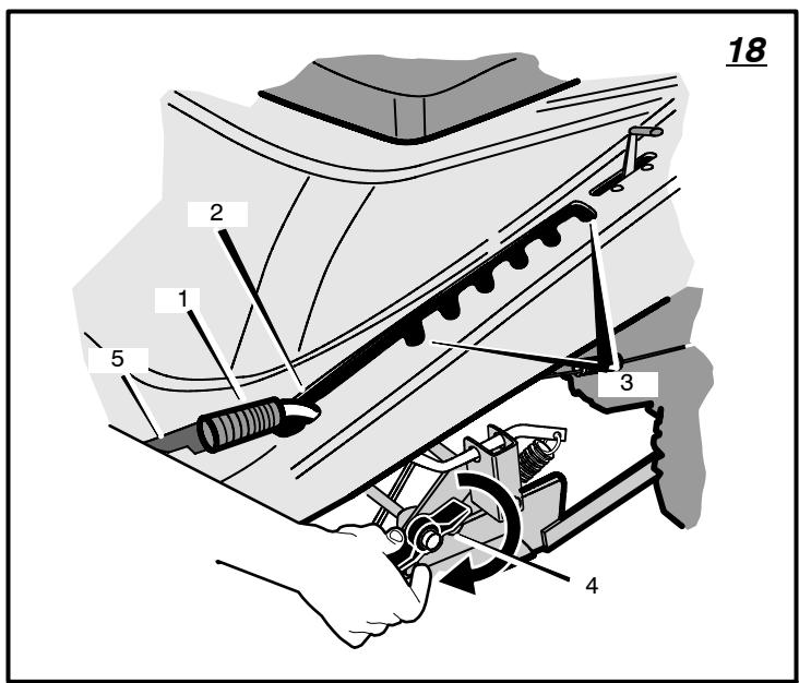
(Figure 18) Move the lift lever (1) to the LEVEL ADJUSTMENT position (2).
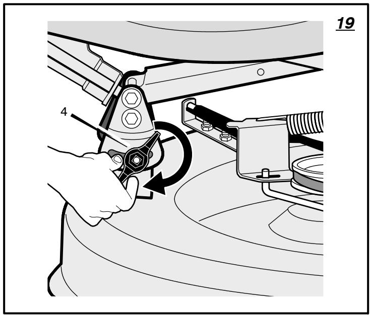
- (Figure 18 and 19) Loosen the front and rear adjuster knobs (4). Make sure both sides of the mower housing are setting on a flat surface. Also, make sure the lift links and adjuster plates are loose and can easily move up or down.
-
Tighten the front and rear adjuster knobs (4). Make sure the adjuster knobs (4) are tight. If necessary, use a wrench to tighten the adjuster knobs (4). For plastic adjuster knobs (4), tighten to a torque of 7 foot pounds (9,5 N-m). For metal adjuster knobs (4), tighten to a torque of 10 foot pounds (13,5 N-m).
-
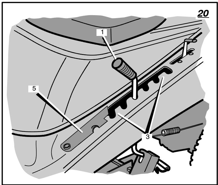
(Figure 20) Raise the lift lever (1) from the LEVEL ADJUSTMENT position (2) to a CUTTING HEIGHT position (3).
- Close the cover (5).
- Mow for a short distance. If the height of cut is not level, repeat the above steps.
CAUTION: Do not operate with the mower housing in the LEVEL ADJUSTMENT position (2). If you operate in the LEVEL ADJUSTMENT position (2), the mower housing and blade will be damaged.
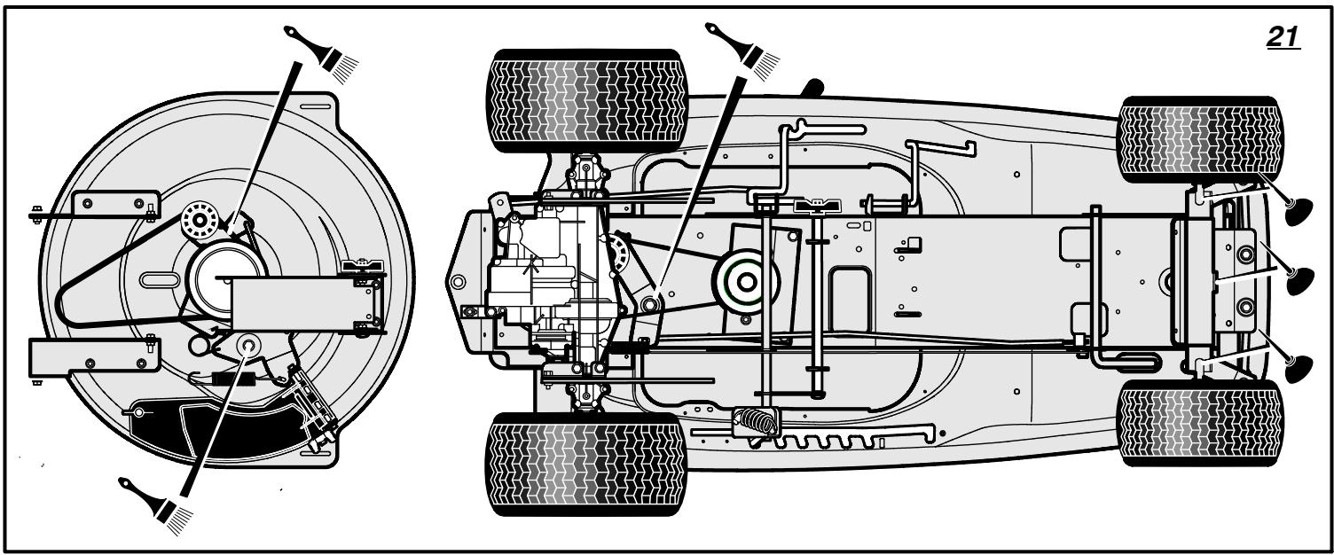
Where To Lubricate (Figure 21)
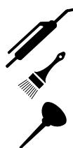
Models with grease fittings:
Lubricate with grease gun.
Apply grease with a brush to the areas shown.
Lubricate the areas shown with engine oil.
NOTE: Apply grease to the steering gear assembly.
CAUTION: If the unit is operated in dry areas that have sand, use a dry graphite spray to lubricate the unit.
Check The Tyres
Check the air pressure in the tyres. Tyres with too much air pressure will cause the unit to ride rough. Also, the wrong air pressure will keep the mower housing from cutting level. The correct air pressure is: Front Tyres 0,97 BAR (14 PSI), Rear Tyres 0,69 BAR (10 PSI).
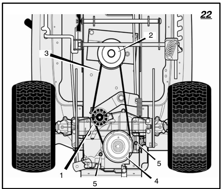
How To Replace The Motion Drive Belt (Figure 22)
- Remove the mower housing. See the instructions on "How To Remove The Mower Housing".
- Completely push the pedal forward and engage the parking brake.
- Remove the idler pulley (1).
- Loosen the belt guides (5) next to the drive pulley (4).
- Remove the motion drive belt (3) from the drive pulley (4).
- Remove the motion drive belt (1) from the stack pulley (2).
- A correct replacement part or assistance is available from an Authorized Service Centre in your area.
- To install the motion drive belt, reverse the above steps.
- Check the routing of the motion drive belt (1). Make sure the motion drive belt is installed correctly on the idler pulley (2). Make sure the motion drive belt (1) is inside all the belt guides.
- Before you use the unit, check the adjustment of the clutch. See the instructions "How To Check And Adjust The Clutch".
- Install the mower housing. See the instructions "How To Install The Mower Housing".
How To Replace The Mower Drive Belt (Figure 14)
- Remove the mower housing. See the instructions on "How To Remove The Mower Housing".
- Pull the belt retainer (1) away from the idler pulley (2) and remove the mower drive belt (3).
- Pull the brake pad (7) away from the jack-shaft pulley (4) and remove the mower drive belt (3).
NOTE: Replace the mower drive belt (3) with an original equipment belt from an authorized service center.
- A correct replacement part or assistance is available from an Authorized Service Centre in your area.
- To install the motion drive belt, reverse the above steps.
- Install the mower housing. See the instructions on "How To Install The Mower Housing".
- Before you mow, check the blade rotation control. See the instructions on "How To Adjust The Blade Rotation Control".
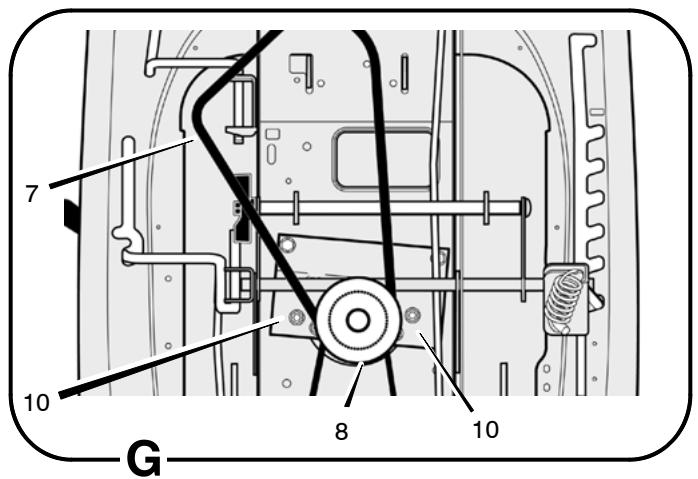
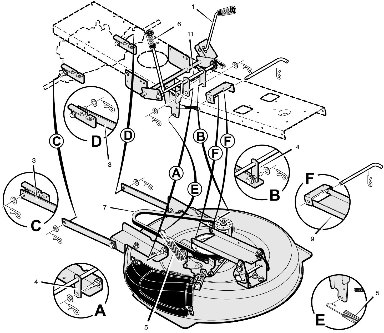
How To Remove The Mower Housing
- (Figure 6) Move the blade rotation control (1) to the DISENGAGE position (8).
- (Figure 18) Move the lift lever (1) to the LEVEL ADJUSTMENT position (2). NOTE: Make sure the lift lever (1) is locked in the LEVEL ADJUSTMENT position (2).
- (Figure 25) Remove the hair pins and the washers from the rear suspension arms (3). See illustrations "C" and "D".
- Remove the hair pins and washers from the suspension links (4). See illustrations "A" and "B".
- Disconnect the extension spring (5) from the blade control rod (6). See illustration "E".
- Disconnect the front hanger (9) from the frame support. See illustration "F".
- Remove the mower drive belt (7) from the stack pulley (8). See illustration "G".
- Pull the mower housing away from the right side of the unit.
- To operate without the mower housing, move the lift lever to the TOP position.
- To install the mower housing, reverse the above steps.
- Make sure the mower drive belt (7) is inside all the belt guides (10) and is also below the spacer tube (11).
How To Install The Wheels
If the wheels must be removed for service, make sure they are installed as follows:
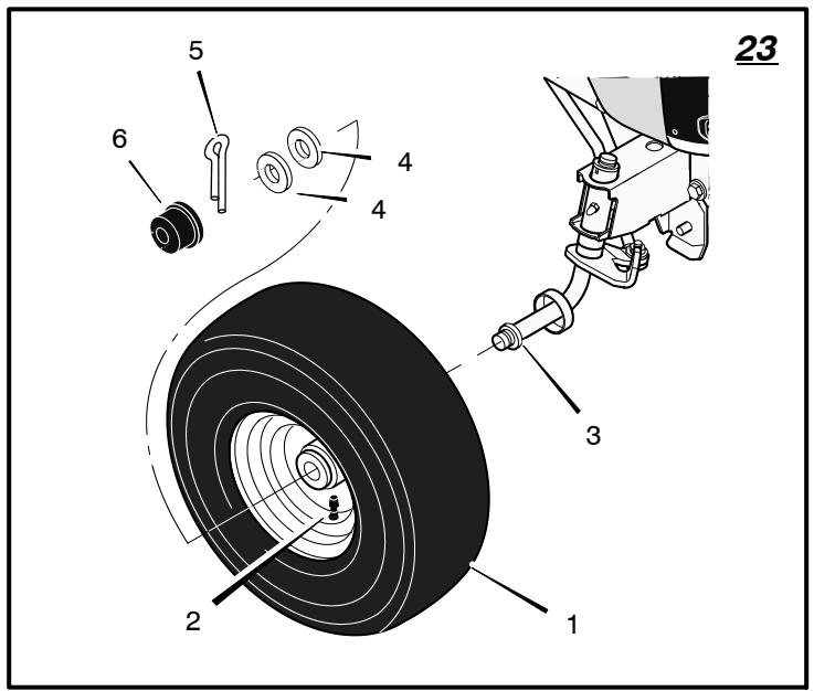
Front Wheel (Figure 23)
-
Make sure the valve stem (2) is to the outside. Slide the front wheel (1) onto the spindle (3).
-
Fasten the front wheel (1) with washers (4) and cotter pin (5). Bend the ends of the cotter pin (5) apart to keep the front wheel (1) on the spindle (3).
- If your model has hub caps (6), install the hub caps (6). Make sure the washers (4) hold the hub caps (6) in place.
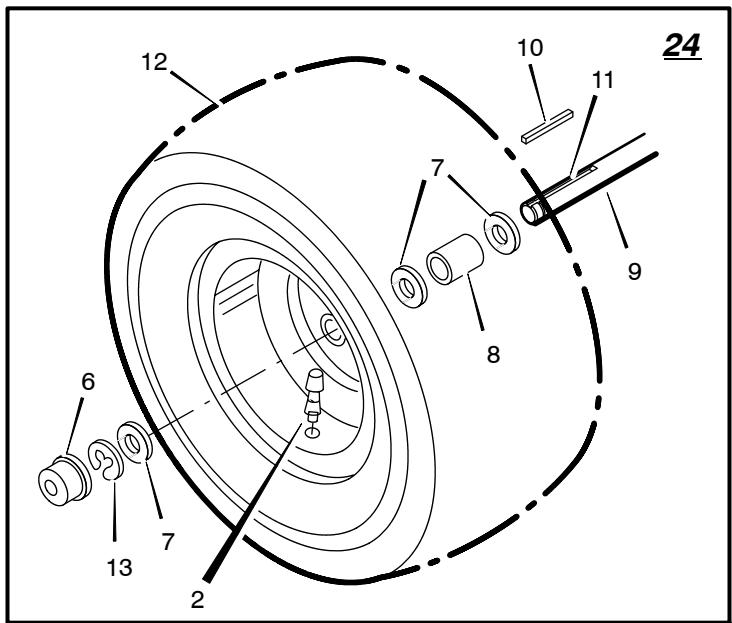
Rear Wheel (Figure 24)
- Install the washers (7) and spacer (8) onto the axle (9).
- Mount the square key (10) in the key slot (11).
- Make sure the valve stem (2) is to the outside. Align the slot in the rear wheel (12) with the square key (10). Slide the rear wheel (12) on the axle (9).
- Fasten the rear wheel (12) with washer (7) and e-ring (13).
- If your model has hub caps (6), install the hub caps (6). Make sure the washer (7) holds the hub caps (6) in place.
How To Replace The Fuse
If the fuse is blown, the engine will not start. Remove the fuse and replace with a 15 amp. automotive fuse.
Storage (over 30 days)
At the end of each year, prepare the unit for storage as follows.
- Drain the fuel from the carburettor and the fuel tank. Change the engine oil. See the engine manufacturer's instructions.
- Clean the entire unit.
- Charge the battery.
How To Order Replacement Parts
The replacement parts are shown either on the back pages of this Instruction Book or in a separate Parts List Book.
Use only manufacturer's authorized or approved replacement parts. Do not use attachments or accessories not specifically recommended for this unit. In order to obtain proper replacement parts you must supply the model number of your mower (see nameplate).
Replacement parts, except for the engine, transmission, transaxle or differential, are available from the store where the mower was purchased or a service shop recommended by the store.
Warranty service is available only through Authorized Service Dealers. Locate your nearest dealer in our locator map at www.murray.com.
Replacement parts for the engine, transaxle, or transmission, are available from the manufacturer's authorized service centre found in the commercial pages of the telephone directory. Also, see the individual engine or transmission warranties to order replacement parts.
When ordering the following information is required:
(1) The Model Number
(2) Serial Number
(3) Part Number
(4) Quantity
- Clean the air filter.
-
Replace the fuel filter.
-
Clean the extension tube and the connector tube (applies only to model with rear discharge grass bag).
PROBLEM: The engine will not start.
- Follow the steps, "How To Start The Engine" in this book.
- Electric-Start Models: Clean the battery terminals. Tighten the cables.
- Check for a loose wire. Tighten the limit switches. (See the wiring diagram.)
- Drain the fuel tank. Clean the fuel line. Replace the fuel filter.
- Remove the spark plug(s). Move the throttle to the SLOW position. Turn the ignition key to the ON position. Try to start the engine several times. Install the spark plug.
- Replace the spark plug.
- Adjust the carburettor.
PROBLEM: The engine will not turn over.
- Follow the steps, "How To Start The Engine" in this book.
- Electric-Start Models: Charge the battery.
- Replace the fuse.
- Check the wiring harness for damage or a loose connection. Repair the damaged wire.
- Electric-Start Models: replace the solenoid.
Recoil-Start Models: replace the module.
PROBLEM: The engine is difficult to start.
- Adjust the carburettor.
- Replace the spark plug.
- Replace the fuel filter.
PROBLEM: The engine does not run smooth or has a loss of power.
- Check the oil.
- Clean the air filter.
- Clean the air screen.
- Replace the spark plug.
- The engine is working too hard. Use a lower gear.
- Adjust the carburettor.
- Replace the fuel filter.
PROBLEM: The engine does not run smooth at fast speed.
- Replace the spark plug.
- Adjust the throttle control.
PROBLEM: The engine stops when the blades are engaged.
- Check the wiring harness for damage or a loose connection. Repair the damaged wire.
- Grass bag must be installed (applies only to model with rear discharge grass bag).
PROBLEM: On slopes, the engine stops.
- Mow up and down slopes. Never mow across a slope.
PROBLEM: The engine will not idle.
- Replace the spark plug.
- Clean the air filter.
- Adjust the carburettor.
- Adjust the throttle control.
- Drain the fuel tank. Clean the fuel line. Replace the fuel filter.
PROBLEM: A hot engine causes a decrease in power.
- Clean the air screen.
- Check the oil.
- Adjust the carburettor.
- Replace the fuel filter.
PROBLEM: Excessive vibration.
- Replace the blade.
- Check for loose engine bolts.
- Decrease the air pressure in the tyres.
- Adjust the carburettor.
- Check for a damaged belt or damaged pulley. Replace the damaged parts.
PROBLEM: The grass does not discharge correctly.
- Stop the engine. Clean the mower housing.
- Raise the height of cut.
- Replace or sharpen the blade(s).
- Move the shift lever to a slower speed.
- Move the throttle control to the FAST position.
- Replace the spring for the blade idler.
PROBLEM: The mower housing does not cut level.
- Check the air pressure in the tyres.
- Adjust the level of the mower housing.
- Check the front axle. If the front axle does not freely pivot, loosen the axle bolt(s).
PROBLEM: The mower blades will not rotate.
- Check the mower drive belt. Make sure the belt is installed correctly.
- Replace the mower drive belt.
PROBLEM: The unit will not move when the clutch is engaged.
- Check the motion drive belt. Make sure the belt is installed correctly.
- Adjust the clutch.
- Replace the motion drive belt.
PROBLEM: The unit moves slower or stops when the clutch is engaged.
- Adjust the clutch.
- Replace the motion drive belt.
PROBLEM: When the clutch/brake pedal is released, belt noise can be heard.
- Temporary belt noise does not change the operation of the unit. If belt noise is continuous, check the routing of the belt. Make sure the belt is inside all belt guides.
- If the noise is continuous, adjust the clutch.
PROBLEM: The rear wheels spin over uneven terrain.
- Check the front axle. If the front axle does not freely pivot, loosen the axle bolt(s).
PROBLEM: The transaxle is difficult to shift between gears with the engine running and the clutch depressed.
- Check the clutch adjustment to make sure the belt stops when the clutch pedal is depressed with the transaxle in (N) neutral.
- Check the belt guides around the transaxle drive pulley. Make sure the belt guides do not touch the pulley.
TABLE DES MATIERES
PICTOGRAMMESINTERNATIONAUX 18
INFORMATIONS GENERALES 19
POUR UNE UTILISATION EN Toute SECURITE 19
MONTAGE 20
FONCTIONNEMENT 21
TABLEEAUD'ENTRETIEN 23
ENTRETIEN 24
TABLE DE DEPANNAGES 27
PICTOGRAMMES INTERNATIONALAUX
Lubrification (Figure 21)
PROBLEM: vibration excessive.
3. WAARSCHUWING: Benzine is zeer brandbaar.
Opbevaring (over 30 dage)
Ved aflsutnng af brug for aret, flog folgende procedure for opbevaring af plaenetraktoren.
PROBLEM: Overdren vibration.
PROBLEM: Tugev vibratsoon.
Heo6cnyxnaBaem aKKymyIaTOPHa 6aTape (Pnc.3)
Baxho!IpeedHaayaIOMcKaunBaHnA
PpOBepuTb ypoBeHb MOTOPHO macJa
3aJIHTb 6eH3nH B TOJINBHyBbI 6aK.
IpoBepntb ypoBeHb ycTaHOBKn Kopnyca KocnIKn.
PpOBePntb DaBJeHne BO3dyXa B uHHax.
IopcoeHnHTbKa6eJnДЯ npKJIIOUeHnAkkymyIaTOpHOI 6aTapei.
3aKJIIOUHTeINbHaNc6OpKa
Kak pa6oTaTb Ha cKJHOHax

OCTOPOXKHO:3anpeuaetcnaeepBnraTbCBABepxNINBn3noCKNoHAM,KOTOpBIEABLIAOTCA
CINIUKOM KpyTbIe DnIpeBnXKeHn. HnKOrDa He nepemeuaTecb nonepek CKJIOHa.
- Перед Движеним Вьрх ИИ ВиЗи по склону, рычаг певеклоченя певедч седует установпь на самую НИЗКУОСКОPOCTь.
- He donyckaetc octaHaBnBaTbca nI IN 3MeHnTb yCTaHOBky CKOpOCTn Ha cKIOHe. EcIn Bam Heo6xOIMo OCTaHOBnTbC,TO CneJyET 6bICTpo BbIXaTb Bnpeed neJaIb CuenJIeHn / TopMo3a.,N BKJIouHTb CTOrHOuHb TOpM03.
3.ДЯВОЗБНOBЛЕNHЯДВИЖЕNHЯ,CLEДУТпроверпь,чTO рыагпескюЧЕNHпесдау yCTaHOBJIENHa camyu Hn3kyoCKopoCTb.IpeMeCTnTB pbyar ynpabJIeNHINДрocSeIem B nIoJoxeHne SLOW(MeJIeHHO).MeJIeHHO OTnyCTnTB neJaIb. -
EcIn BbI BbHxJHbI OCTaHaBJIbIbTaCnIN BO3O6HOBJTa DBIXeHne Ha CKIoHe, TO BCerJa DOJXHo 6bITb IOCTaTOUHO MecTa DnA 6Noka dner erO BbKaTbIBaHn, KOrDa Bbl OTnyckaTe TOpMo3 n BkIIouaTe cuenneHne.
-
Co6IIOdaIte MaKcImMaJIbHyIO octopOxHocTb pIn CMeHe HapRaBLeHnRA DmIXeHnHa cKJIOHe.IPi NpOBoPoTe Ha cKJIOh, CNeJyET nepEmeCTnTb pbYar ynpaBLeHn DpoCSeHem B nIoJoxHe SLOW (MeJleHHO, YTO6bl MmHmMn3IpOBaTb BepoTHOCTb npOnCseCTBnA.
Ipeed 3anyckom DnurataeJ
CoBeTbI IO MyJIbUHPOBaHHIO
Korda nCnoJb3yETcnpncnocBJeHne dIy MylbnyipoBaHnry, TpaBa pExeTcH NaOeyb MaIeHbKNe KycOuyKn. 3Tn MaIeHbKHe KycOuyKn 6byT 6bICTPO naDaTb BnH3. NocKoIbKy NiTaTeIbHbIe BeIeCTBa BO3BpaAoiTCa B IOUY, To JLykaJIe NOTpe6yETcM HeBWe yDo6peHn. DnI npabInbHorO MylbnyipoBaHnry TpaBbl CJIeDyET BbINOnHnTb Yka3aHHbE HNKe DeiCTBn..
1.Перемecпь рьчаг ураленя
дросселов поожени FAST (Быстpo).
Работаь с косилков прин необшою
скорoctи леремшени.Еслсckорoctь
6удет слишkom 6лшо,TOтраване
6удет IMetb poBнь срз.
2. HoxdoJxhenBcerda IMeTbXopo0o 3aToOeHHeJe3Bne.I3HOWeHHeJe3Bne MOyT CTAbIpnuHoiNoKeJIteHnKOHKnOB TpaBnHOK.
3. CneyuET ybeintbca, YTO TpaBa RbIaTc cyxon. Mokpyo TpaBy Tpydhe ckaunBaTb.
4. OtperynipoBaTb BlicOTy noDbema Kopnyca Kocnkn TaKIM o6pa3OM, YTo6bl cpe3anacb TOnbKO BepxHra TpeTb TpaBb. EcIn Tpaba OeHb BlicOKa, TO CneJeYET UCTAHOBITb MaKcMaJIbHyO BlicOTy noDbema KOpNyCa Kocnkn. 3aTeM ONyCTNTb KOpNyc Kocnkn DnBTOPO Cpe3aHHa. KpOME ToR, BmecTo NcIONb 3OBAHnI PONHOJ WINPHb KOpNYCA KOCnIKM, MUYbUHPOBaHHe BbINOHNHETC C NOJOBHHOH WIPINHOJ.
5. Ouchntb HxHIOU qactb Kopnyca Kocnkn. OctaTkn TpaBbl npyro cop Moryt NOMEwab HaJneJaue paObe Kocnkn
6. EcIn TpaBa BbIpaCTaET 6bIcTpo,To MylbUHpOBaTb CneJeYt YaSe.
7. Ecnn yuactok Hxkdaetc B ynyuweHH, TOMyIbYnPOBaT cJeDyET DBAxDbI.
TABJIULA BbIIOJHHeHNA TEXHNUeCKOTo OBCJNUXBAHNA
BbINOpHeHnEM npOBepKn, perynpOBKn nnppeMOHT
HE06XODIMO OTCOEINHHTB pOBoD OT CBEu 3axnraHna, YTObI NCKJIIOHTb BO3MOxHOCTb CnyauHoro 3aNycka dBnraTeJ.
ПРМЕЧАНЕ:Единцeи n3мерени MOMENTa 3aTЯЖКИ AВЛЯТСЯ ФУТ HaФуNT (B MeTpчecKo CnCTeME HbIOTOH Ha MeTp nJIN H-M).ЗТа BENчINA NOKA3bIBaET,ΚΑΚ CnJIbHO DoJnxHbI 6bITb 3aTЯHtbl RaKa nJIN 6OJT.МOMENT 3aTЯЖКИ n3мерется c nOMOuьIO DInHaMOMEtPruYeCKOrO KJIouya.
OTCOEHNHTb npOBOD OT CBeuN
3aXnraHna.EcnnHOxHaToJKNHeTcHa npenrTCTBne,TO CJeDyET BbIKIIOHTb DnRaTeJIb.PIOBepNTb 6NoK ha NOBpeXdEHN. JIe3Bn HOXA MeIoT ocTpbIE KpOMKn. PnO6paUeHN C HoxKom CJeDyET NcNOJIb3OBaTB NepuATKn NII TKAhBi MaTePnAIn dJIr 3aunTbI CBOUX pyK.
EcIN Bby6yndeTe noDaepxnBaTb HOK (1) ocTo po 3aTOUeHHbIM n IpOBepaTb erO Ha
IOBpeKdENHIA,TOHOX6yIeTJUHHepe3aTbN 6yIeT60nee6e3oNaChbIMBa6Ote.
PepnoDnueckn npOBepaTe HOx Ha ue3MepHbI n3Hoc, TpeuHbI INn DpyTne NOBpexKdEHHa. PepnoDnueckn npOBepaTe raKy (3), KOtopa KpeNT HOX (1).
3aTAAKKa rAaKNuHn HOxA MoXeT CTAb npuHHo HecuaCTHO ClyuA.
- 3aTAYb rAky (3), KOTOPaJ KpeNT HOX (1), C MOMENTOM 3aTAAKKN 30 cyTOB Ha cyHT (41,5HM).
10.YctaHOBtB KOpNc KocuNk. CmOTpnte NyHKT "KaC hTb KOpNc KocuNk".
Kak npobepntb pa60ty pbuara ynpablenn BpauneHem HOka

OCTOPOXHO: YtO6bI n36eKaTb TpaMbI, pbUar ynpaBLeHn BpaueHem HOxa DoJxHe
pa60taTb DOnJXHbIM 06pa3OM.
PnHOpMaJIbHOJ 3KcIpyaTauu, pUHaR ynpaBLeHn BpaUeHnEM HOxA He Tpe6yEt perynipOBKn. Ondako, ecIn 3ΦΦeKTHBHOCTb Cpe3AHn CHNJaETCn, nIN eCN KaueCTBO Cpe3AHn JBAJIaETCn IIOXIM, TO HeO6XoJIMO BblONHtB CNeDyUOUIne N3MeHEHn.
1740464
- Пи скашиваньи селүует убүдүсү, чтөрөчаг упрааленя дроссаннхоштсг в положени FAST (Быстpo).
- (Pnc.6) Iepemecntb pbyar ynpaBneHn BpaueHnem HOxa (1) B noLoXeHne DISENGAGE (BbIKJUcHo) (8).
- OctaHOBtbpabOtyDbIrataJIy. OToeDHHb npoBOd OT CBeuH 3aXnIraHna.
4.Поверпь HOK(и).HOKdoJIжEN BCERda IMMeTbXopoIoo 3aTOUeHHOJe3BVE. I3HOuWeHoeJe3BNEMOrTCTaTb npuHoi NOKeJIteHnKOHKnOB TpABnHOK. - EcIn KaueCTBO cpe3a He yIyUshnIOcb, TO CJIeJyET 3aMeHnTb npuBoHOH pEmHeB KocuIKn, CMOTpNTe nyHKT "Kak 3aMeHnTb npuBoHOH pEmHe B KocuIKn".EcIn 3aMeHa peMnA He yCTpaHReT pObIeMb,TO CJIeJyET OTPiABnTb 6JOK B CePTnФuNpOBaHHbI M3ROTOBHTeM eHTP TEXHneCKoR O6cIyXHBAHn.
6.ПеремecntbpyharynpaBLeHnB bpaueHnem Hoxa(1)ВnoJoxeHnDEsENGAGE(BbIKNoyeHo)(8).OCTaHOBtbpabOTyDbIrataTeJI.OTcoEduHtbpoBOdOT CBeu3axKunraHnA. - (Pnc. 14) Пюверпь pa60у Торmo3a ножа. Пюверпь рукошки. Пюверпь, чTO TOPMO3ная Нakладka (7) ПLOTНО рижимаетс КшИВ.

OCTOPOXHO: EcIn Topmo3nHa NaKlaJaKa (7) He npxkMaetcN ILOTHOK WKNBy, TO CJeNyET
OTnpaBntb 6IOK B cepTnΦnCnPobAHHbIMN3ROTOBNTeJIem CEHTp TEXHnueCKORO06cIyXnBaHnI.
- (Pnc. 6) IpepeMeCTnTb pbIur ynpaBneHn BpaueHnem Hoxa (1) B noJIOXeHne ENGAGE (BkIIOyeHo) (9).
- (Pnc. 14) Пюверпь Накладки похma HOxa (7).Есин Накладки Крзмерно ИЗношени ИИПОВждны,TO CLEДуET заменчы y3лы ТОМОзА HOxa.Оригинальные залисные части IN TExHnueckaя подөрЖК могут Быт IN poluyleь B сетуншпцированHom ИЗROTOВITelem цHTpe TExHnueckoro Oбслuyнваня.
10.ПоДСоЕДИНТьnpвОДКсБеЧаЖИАн.ВылОЛНТьСКашИВанUE He6OЛьшOrOучakиИСCHOВApOBeРNTь pa6OTy pbUarayynpaBNeHnBbpaSeHnEMHOXa.
11.EcIn BbI nepeMeCTte pbyar ynpaBHeHnBpaueHnEM HOxa B nOLOXeHnDEsENGAGE (BbIKNoUeHO),TO BCEDbNKeHnOCTaHOBATcB TceHne PAnTeCekyHd. EcIn DbNKeHnpePMn HnBpaueHnEOHXa npoDOnJxaeTc,TO CJeNyET Pa3 BKIOUcTaB n CHOBABbKIOUcTaB BpaueHnEOHXa dJaYdaJIeHnH3NIuHero KOJIuYeCTBa pe3INbI c HOBOrnpNvBOHorO pEmn KocINKn. EcIn BamTpe6yETcTexHnuecka NOpDepeXkKa,TO 06paauTeCb, IOXaNyIcTA,B cepTnΦnIupOBaHHb N3rOTOBtJeM ceHTpTexHnueckoro OcbLyXbAHnA.
Kak OtperyunpoBaTb pbUar nepekIoueHn nepeDau (Pnc. 15)
Ecnn HeItpaIbHoe (N) noIOxHeHne pIyura nepeKluOeHn IpeJaU He COOTBeTCTByet HeITpaIbHOMy NOIOxHeHIO Ha KOp6Ke
pepaT,TO3OTpBuaH Heo6xoIIMO OtpeYIInpoBaT CLeJeUOuM 06pa3OM.
- OctaHOBntb pa60Ty DnBaTeJEA.
- ChaTb peryI npOBoHy o raKy (2) c BnIKn nepeKIOUeHn (3).
- Поберпь, чт рычаг посяклочени поеданхоитсь Нйтpaльnom (N) NOLOXKeHn.
- TOnkHyTb 6IOK BnepeI. IpoBepntb, YTO Kopo6ka nepeJaH hXoJITcB HEnTpAlbHOM (N) noJIOKeHHN.
5.ДЯ COBMeUeHЯperyIInpoBOuHOnraKn (2)COTBepCTnEM Bvnke nepeKluOeHn (3),cneDyeT BpaaTaBraKy(2). - YctaHOBt b peryInpoBOHy o raKy (2) Na BnKy nepeKlioueHna (3).
- Поберпь, чTo HeItpaNBHoe (N) NOLOXKeHne pbluara nepeKJIIOUeHnI nepeJaC COOTBeTCTByET HeITpaNBHomY (N) NOLOXKeHnIO KOpO6Kn pepeJaC.
Kak npobepntb n OtperynipoBaTb cuenlenne (Pnc. 16)
Ecn npBDOHn peMeHB DnXKeHn npocna6IeN,TO cUeJIeHne 6yIeT npObYKcOBbIbATb npi NOJbEMHa CKIOH, pni cnYcKe Co CkIoHa, pni 6yKcIpOBKe TAgEnoRo rpy3a, nIn Jx He 6pOK He 6yIeT DnIraTbcn BpePe. B 3tOM cnyae Heo6xoDm0 OTpyNIpoBaTc eIeJIeHne CNeDuOuIM m 6pbzom.

OCTOPOXHO: Npeed BbINOJIHeHem npOBepKn, perynpOBKn nnn pmoHTa 6loka,
HEO6XoDnMo OTCOEiHNHTb PNOBOD OT CBeu 3aXnraHn, YTO6bl NCKJIOUHTb BO3MOxHOCTb CnyauHoro 3aNycka DBnraTeJI.
- Пюверпь похожденье пивогногоремя дыжени. Пюверпь, ут ремьустанов лравильно, и похолит попа3am BCex ременьхшквов.
- CHATb 7nnnT (1), 7a6y (2), n Topmo3Hy npjxHny (3) c perynpyuoei raiKn (4).
- CHATb perynpuyouyraKy (4) cyzta Topmo3Horo pbiura (5).
- COBmecTntb OTBepCTne B TopMo3HOM pbUare (5) C 3aJHei YacTbIO npope3n B pame.
5.Вдавит bary ynpablenma Myftoi cneplenna (6) B naprablenn 3a.dnei qactn.Bpaaatb perynpyemyu raiky (4) doTex np, noka raika He 6ydet npoxoNt byee3 OTBepCTne B TOPMO3HOM pbIcare (5). - YCTaHOBtB peryIpyUOyU raKy (4) B TopMo3HOb pIyIar (5) nB TopMo3HyOpnyKIny (3). 3aTAYb BMeCTe C wai6oB (2) n WpIInHTom (1).
- Ecni peMeHb BCE eue npocKaJIb3bIbAeT nOcIe peryIuPOBKn CcIeJIeHnra, To 3TO O3NaHaaeT, YTO npIBoNDHOpeMeHb DBIXeHn I3HOWe HnnIOBpeXdEh, IN IOJNeKHT 3aMeHe.CmOTpInTe pYHKT "KaK 3aMeHNT pINBODHOpeMeHb DVBIXeHnra".
Kak npoBepuNb n OtperynnpoBaTb Topmo3 npuBoDa (Pnc. 17)
OCTOPOXHO: YTo6bI n36ExKaTb NCKp0o6pa3oBaHnra, Heo6xOaHMo OTOeDNHTb Chehbl KaebI dIa
NODKJIIOUeHnAkkymyIaTOpHO6batapei (8)OTOTPnuaTeNbHOI (-) KJIeMMbl, IpeXdE Yem OTcoeHNrTaKpaChbI Ka6eIb (5).

OCTOPOXKHO: B aKKymyIaTOPHoi 6aTaape copekntc cepna KncJota, KOTopaa npedctablaet
OnacHOCTb DnI KOKN, Tna3 N ODeKDbI. Ecnn KncNoTa nonaTe Ha TeNo nn OdeKdy, To CneJeT npomblb BODOn NOPaxKeHHoe MeCTo.
- OToeHnHTb YepHbI Ka6eJIb (8) OT OTPuCaTeJIbHOI (-) KJIEMMbI.
- OToeHNHtB KpaChbI Ka6eJIb (5)OT nOToXHTeHOBn (+) KJIemMbI (4).
3.ДЯOTCOEДINHEHNAФИКcaTopa6batape (2)OT6batapeHORO NOДHOA(3),CNEdyeT HaxaTbHaHIXKHNIKOHeUФИKcaTopa 6batape (2). - ChaTb aKKymJIaTOPHyO 6aTapeo (1) c npaBoi CTopoHbI 6noka.
1740464
Kak 3apKaTb aKKyMylTOpHyo 6aTapeo (Pnc.3)

OCTOPOXHO:ПиЗардкe akkymлгнорьбатеру Курпь Bocpezaetс. He Дonyckaetс
PnIbJIxKeHne 6aTapeN K IIO6OMy nCTOuHNky NcKp. BbIeJIeMble KNCJIoTHoB 6aTapee Ra3bl MOryt CtaTb PnIuHOB B3pbIBa.
- Парад Зардковakkymлторhoe 6atapen (1), Heo6xOДIMO Chrtb C6Ioka akkymлтopyu 6atapeio (1).
2.ДЯЗAPANKnAKKymyIaTOPHO6aTapeN(1),CLEyETNCIOJIb3OBA Tb12-BOJbTOBoE 3apAnHoe yCTpoIcTBo.3apKaTbpn CnTe TOKaB6ampeB TeueHne1yca. - YCTAHOBINTb aKKymyTOpHyIO 6aTaapeo (1).

OCTOPOXHO: YTo6bI N36eKaTb NCKp0o6pa3oBaHnI, Heo6xOaHMo NOdCoEOHNHTb KpaChbI Ka6eJIb K NTelBJHOI (+) KNEMME, IpEKeJde Yem DNHHaTb YepHbI Ka6eJIb.
4.ПоДСоЕДИНТьКрасьйКаБь(5)К
ПОLOЖИТьнО(+)КЛЕМп(4)с
ПOMOДьЮКрЕДжHbIX3JIEMHTOB,KaK
ПOKaЗАHOHa pICyHKe.
5. ПодсоeДиНть чрнь Кабь (8)К OТрицалов (-) Клеммс с помоьк Кренихызlementob, KaKпokаЗанHa pисунke.
6. 3aKpeNTbФHKcatOp 6aTapeu (2)Ha 6aTapeHOM NOdohe (3).
Kak BbipOBHrtb Kopnyc KocnIKu
EcIn KOpnyc Kocniln BbIpOBHeH,TO HOx 6yDet Cpe3aT bJeH, n Lyjka Ka 6yDet BBIgnaTeB lyu.

MoJenC TABOTHUMM: CMA3aTb c nOMOsbI WpNcA Dn I NaCTHNO CM3KH.

Hahectn KnctOyKo Cm3Ky Ha Mecta, noka3aHHbIe Ha puncHyke.

Cma3aTb Mecta, Ioka3aHHbIe Ha pncyHke, MOTOpHbIM MacnOm.
ПРИМЕЧАНЕ: Наенти сюй сма3книузелшостерни руневого менизma.
BHIMAHHE: Ecnn 6JOK pa6OtaeT B cyuxn 30Hax, B KOTOpbIX npncyTCTByeT neCOK, TO CneJeYET NcNOJIb3OBaTb a3pO3OJIb rpaHTOBOI CMA3KN IJI R CMA3bIBAHN6Ioka.
TABINUCA NONCKA HENCPPABHOCTEI
- BbInOnHnIte cKaunBaHne BBepx n Bn3 noCKIOHAM. HkOrJa He BblOnHnIte cKaunBaHne nonpeK cKIOHa.