
FIREWIRE SOLO - Audio Interface M-AUDIO - Free user manual and instructions
Find the device manual for free FIREWIRE SOLO M-AUDIO in PDF.
User questions about FIREWIRE SOLO M-AUDIO
0 question about this device. Answer the ones you know or ask your own.
Ask a new question about this device
Download the instructions for your Audio Interface in PDF format for free! Find your manual FIREWIRE SOLO - M-AUDIO and take your electronic device back in hand. On this page are published all the documents necessary for the use of your device. FIREWIRE SOLO by M-AUDIO.
USER MANUAL FIREWIRE SOLO M-AUDIO
FireWire Mobile Audio Interface for Songwriters/Guitarists
Quick Start Guide
This guide is intended to help get you started quickly. In order to achieve optimal usage of your new FireWire Solo, we recommend that you carefully study the enclosed product manual, either after completing the process described in this guide or before.
ENGLISH·FRANÇAIS·DEUTSCH·ESPÁNOL·ITALIANO·日本語
Table of Contents
English 3
Introduction 3
Minimum System Requirements 4
Front Panel Controls and Connectors 4
Rear Panel Connectors 5
Hardware Installation 6
Software Control Panel 6
Contact Us. 8
Francais 9
Thank you for choosing the M-Audio FireWire Solo. The FireWire Solo has been designed to give you a professional, portable audio interface for your laptop or desktop computer. Using the convenience and dependability of the IEEE 1394 (FireWire) bus, the FireWire Solo provides your computer with a high-performance, high-resolution audio interface, complete with microphone, instrument and line-level inputs, in a rugged, lightweight, and highly portable design.
This Quick Start Guide is meant to get you up and running as quickly as possible. Please consult the User's manual for more detailed information.
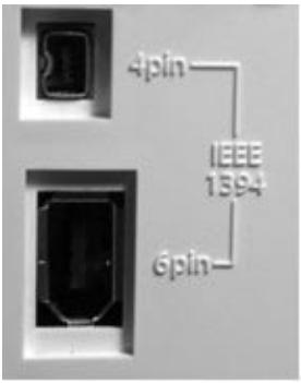
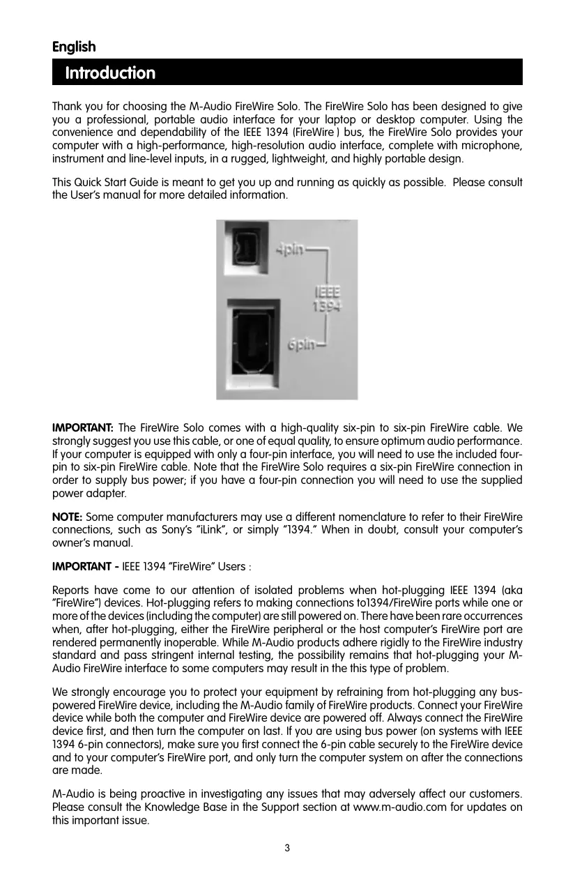
IMPORTANT: The FireWire Solo comes with a high-quality six-pin to six-pin FireWire cable. We strongly suggest you use this cable, or one of equal quality, to ensure optimum audio performance. If your computer is equipped with only a four-pin interface, you will need to use the included four-pin to six-pin FireWire cable. Note that the FireWire Solo requires a six-pin FireWire connection in order to supply bus power; if you have a four-pin connection you will need to use the supplied power adapter.
NOTE: Some computer manufacturers may use a different nomenclature to refer to their FireWire connections, such as Sony's "iLink", or simply "1394." When in doubt, consult your computer's owner's manual.
IMPORTANT - IEEE 1394 "FireWire" Users :
Reports have come to our attention of isolated problems when hot-plugging IEEE 1394 (aka "FireWire") devices. Hot-plugging refers to making connections to 1394/FireWire ports while one or more of the devices (including the computer) are still powered on. There have been rare occurrences when, after hot-plugging, either the FireWire peripheral or the host computer's FireWire port are rendered permanently inoperable. While M-Audio products adhere rigidly to the FireWire industry standard and pass stringent internal testing, the possibility remains that hot-plugging your M-Audio FireWire interface to some computers may result in the this type of problem.
We strongly encourage you to protect your equipment by refraining from hot-plugging any bus-powered FireWire device, including the M-Audio family of FireWire products. Connect your FireWire device while both the computer and FireWire device are powered off. Always connect the FireWire device first, and then turn the computer on last. If you are using bus power (on systems with IEEE 1394 6-pin connectors), make sure you first connect the 6-pin cable securely to the FireWire device and to your computer's FireWire port, and only turn the computer system on after the connections are made.
M-Audio is being proactive in investigating any issues that may adversely affect our customers. Please consult the Knowledge Base in the Support section at www.m-audio.com for updates on this important issue.
Minimum System Requirements
Be sure that your computer meets these minimum requirements before installing your FireWire SOLO.
Windows
Pentium III - 500 MHz or higher
128 MB RAM
Windows XP (SP2) with DirectX 9.0b or higher
Onboard FireWire connection or installed PCI card
The FireWire Solo is not supported under Windows 98, Windows ME or Windows 2000.
Mac OS
Macintosh G3/G4* 500 MHz or higher
OS X 10.2.8 or later, 256 MB RAM or
OX X 10.3.5 or later, 512 MB RAM
Onboard FireWire connection or installed PCI card
*G3/G4 accelerator cards not supported
OS X 10.3.5 or later required for Dolby Digital and DTS pass-through with Apple DVD player.
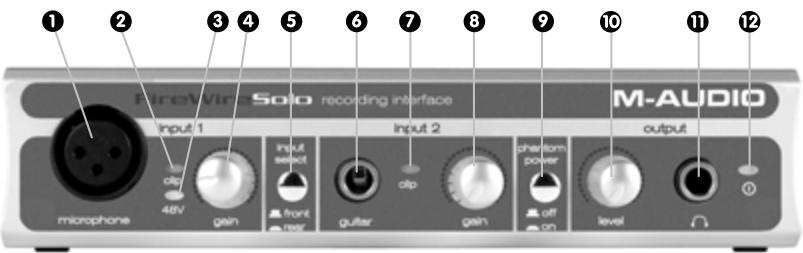
Front Panel Controls and Connectors
1. Microphone Input
Mic-level input on balanced XLR connector. This connector is only active when the Front/Rear Input Selector (5) is set to "Front" (OUT position). Input from this connector appears in your DAW software as a mono signal on the left side of the stereo input pair.
2. Clip indicator
This LED illuminates when the Microphone Input signal level exceeds -1 dBFS. If the Clip Indicator glows steadily, reduce the Microphone Input gain level (4).
3. Phantom Power Indicator
This indicator illuminates when the Phantom Power Switch (9) is pressed, indicating that +48VDC is being applied to the Mic Input (1).
4. Microphone Input Gain
This knob controls the amount of gain at the Microphone Input (1), over a range of 0dB to +40dB or greater.
5. Front/Rear Input Selector
This switch selects which pair of analog inputs will be active. When the switch is in the OUT position, the front panel Microphone Input (1) and Guitar Input (6) are active. When the switch is in the IN position, the rear panel Line Inputs (19) are active.
6. Guitar Input
Instrument-level input on unbalanced 1/4 phone connector, for use with guitars, basses or other instrument-level sources. This connector is only active when the Front/Rear Input Selector (5) is set to "Front" (OUT position). Input from this connector appears in your DAW software as a mono signal on the right side of the stereo input pair.
7. Clip indicator
This LED illuminates when the Guitar Input signal level exceeds -1 dBFS. If the Clip Indicator glows steadily, reduce the Guitar Input gain level (8).
8. Guitar Input Gain
This knob controls the amount of gain at the Guitar Input (6), over a range of 0dB to +30dB or greater.
9. Phantom Power Switch
This switch activates the +48V phantom power, for use with condenser mics requiring external power. When Phantom Power is active, the Phantom Power Indicator LED (3) is lit.
NOTE: It is safe to connect most modern dynamic microphones or line level devices to the channel inputs when phantom power is activated. However, be aware that some older ribbon microphones may be damaged by phantom power, and certain unbalanced line level devices may malfunction or produce an audible hum when phantom power is active. Consult the owner's manual for these devices before you connect them to phantom power sources.
10. Output Level Control
This knob controls the amount of output gain to the rear-panel Line Output (18) and the front-panel Headphone Output (11).
11. Headphone Output
Stereo 1/4" TRS phone jack output for connection of headphones for monitoring the output signal. The volume level is controlled by the Output Level Control (10).
12. Power Indicator
This LED illuminates when the FireWire Solo is powered on, either via buss power or the AC adaptor.
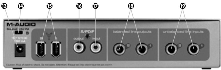
Rear Panel Connectors
13. AC Input
Connect the supplied AC adaptor to this input. The AC adaptor is required when operating the FireWire Solo with only a 6-pin to 4-pin FireWire connection, or when using the FireWire Solo as a stand-alone A/D converter. The AC adaptor is not needed when running the FireWire Solo on a standard 6-pin to 6-pin FireWire connection.
14. Lock Port
This port is provided for use with a standard Kensington-type computer cable anti-theft device.
15. FireWire Ports
Two FireWire (IEEE 1394) connectors. Use one to connect to your computer's FireWire port. The second may be used as a throughput, to chain additional devices on the FireWire bus.
16. S/PDIF Output
S/PDIF digital output on coaxial RCA connector.
17. S/PDIF Input
S/PDIF digital input on coaxial RCA connector.
18. Line Outputs
Balanced/unbalanced analog line outputs on 1/4'' TRS phone connectors. The signal level to these outputs is controlled by the front-panel Output Level Control (10).
19. Line Inputs
Unbalanced analog line inputs on 1/4 phone connectors. These connectors are only active when the front-panel Front/Rear Input Selector (5) is set to "Rear" (IN position). Input from these connectors appears in your DAW software as a stereo input pair.
Hardware Installation
NOTE: Do NOT connect the FireWire Solo to your computer until you have run the installer program and completed the installation.
Once you have run the installer, power down your computer. Then connect the FireWire Solo to your host computer's FireWire port using the included cables. If you are using bus power (on systems with IEEE 1394 6-pin connectors), make sure you first connect the 6-pin cable securely to the FireWire device and to your computer's FireWire port, and only turn the computer system on after the connections are made.
Software Control Panel
The FireWire Solo control panel is installed in your system when you complete the driver installation procedure. To open the control panel:
In Windows - A tiny "knob icon" will be placed in the system tray, generally located at the bottom of your Windows desktop. Double-click this icon to open the control panel.
On the Mac - The FireWire Solo control panel can be found in the system preferences.
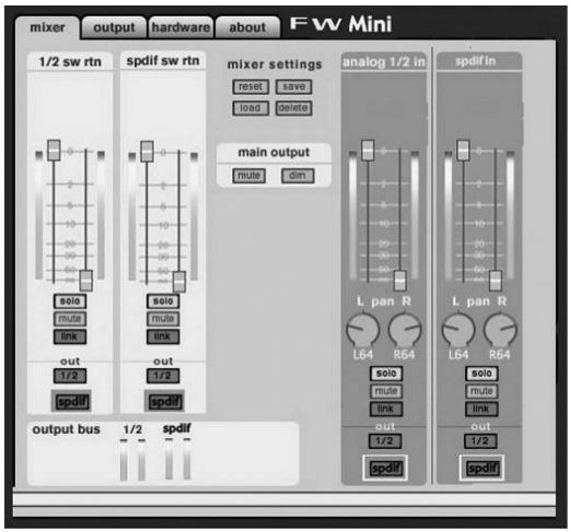
Mixer Page
The Mixer page provides output routing and control of the FireWire Solo's analog and digital inputs, as well as the four virtual channels returning from your Digital Audio Workstation software. It also provides input and output level meters, level controls, stereo linking, solo and mute functions.
Hardware Page
The Hardware page gives you access to important information and functions of the FireWire Solo.
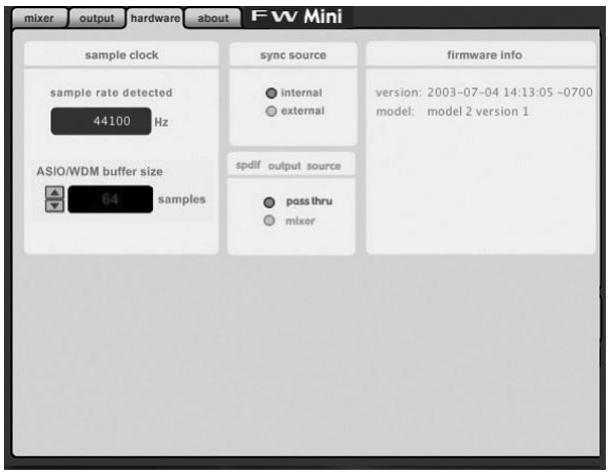
■ Sample Rate Detected - This field displays the currently-detected sample rate from the currently selected incoming sync source.
■ ASIO/WDM Buffer Size - In this field you can select the buffer size you wish to work with. Smaller buffer sizes result in lower latency (latency refers to the time it takes for your input signal to pass through your audio software and appear at the outputs), but may not function well with slower systems.
Sync Source - This field allows you to choose between the FireWire Solo's INTERNAL clock and an EXTERNAL S/PDIF clock source.
■ S/PDIF Output Source - Selecting "mixer" routes the signals assigned to the S/PDIF output from the control panel mixer to the S/PDIF output. Selecting "Pass Thru" allows a surround-encoded stream such as AC3 or DTS to be sent to the S/PDIF output.
Contact Us
For additional help, technical support is available on our website at www.m-audio.com, where you can fill out our technical support form.
Alternatively, you can email us at support@m-audio.com,
Or contact us by phone at: (626) 633-9055.
Technical support is available by telephone from 7am - 7pm PST

M-AUDIO FireWire Solo

Tested to comply with
FCC standards
Tested to comply with
FCC standards
Tested to comply with
FCC standards
Alternatively,我会 invite you to participate in a new competition.
Tested to comply with FCC standards
Tested to comply with
FCC standards
Tested to comply with
FCC standards