
WEB SMART SWITCH - Network switch D-LINK - Free user manual and instructions
Find the device manual for free WEB SMART SWITCH D-LINK in PDF.



| Brand | D-Link |
| Model | Web Smart Switch |
| Product Type | Network Switch |
| Category | Managed Level 2 Switch |
| Dimensions (W x D x H) | Approx. 44 x 20 x 4.4 cm (19-inch rack mount) |
| Weight | Approx. 2.5 kg |
| Power Supply | AC power cord, 100-240 V AC, 50-60 Hz |
| Network Interfaces | Ethernet RJ-45 ports (quantity depends on model) |
| Default IP Address | 10.90.90.90 |
| Default Subnet Mask | 255.0.0.0 |
| Default Gateway | 0.0.0.0 |
| Default Password | administr |
| Main Functions | Web management, Telnet, SNMP, SmartConsole, network configuration, LED monitoring |
| Administration Modes | Web interface, SmartConsole utility, Telnet, SNMP |
| Mounting Support | Desktop, shelf or 19-inch EIA rack (brackets included) |
| Ventilation | Convection cooling; leave sufficient space around |
| Installation Safety | Do not place heavy objects, use a grounded outlet, unplug during power outage |
| Maintenance | No special maintenance; clean with a dry cloth if necessary |
| Package Contents | Switch, mounting brackets, power cord, CD with guide and SmartConsole, multilingual quick start guide |
Frequently Asked Questions - WEB SMART SWITCH D-LINK
User questions about WEB SMART SWITCH D-LINK
0 question about this device. Answer the ones you know or ask your own.
Ask a new question about this device
Download the instructions for your Network switch in PDF format for free! Find your manual WEB SMART SWITCH - D-LINK and take your electronic device back in hand. On this page are published all the documents necessary for the use of your device. WEB SMART SWITCH by D-LINK.
USER MANUAL WEB SMART SWITCH D-LINK
Getting Started Guide For D-Link Web Smart Switch
Getting Started Guide
Getting Started
Getting Started Guide
Getting Started Guide
Quick Start Guide
Quick Installation Guide
Getting Started Guide
Installation Guide
Getting Started with This Product
About This Guide
This guide gives step-by-step instructions for setting up all D-Link Web Smart switches. Please note that the model you have purchased may appear slightly different from those shown in the illustrations.
For more detailed information about your switch, its components, making network connections, and technical specifications, please refer to the User's Guide included with your switch.
Step 1 – Unpacking
Open the shipping carton and carefully unpack its contents. Please consult the packing list located in the User Guide to make sure all items are present and undamaged. If any item is missing or damaged, please contact your local D-Link reseller for replacement.
- One D-Link Web Smart Switch
- Rack mounting bracket
- Power cord
- User's Guide CD with SmartConsole Utility program
- One multilingual Getting Started Guide
Step 2 - Switch Installation
For safe switch installation and operation, it is recommended that you:
Visually inspect the power cord to see that it is secured fully to the AC power connector. Make sure that there is proper heat dissipation and adequate ventilation around the switch. Do not place heavy objects on the switch.
Desktop or Shelf Installation
When installing the switch on a desktop or shelf, the rubber feet included with the device must be attached on the bottom at each corner of the device's base. Allow enough ventilation space between the device and the objects around it.
Figure 1. Attaching the rubber feet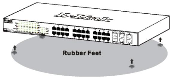
Rack Installation
The switch can be mounted in an EIA standard size 19-inch rack, which can be placed in a wiring closet with other equipment. To install, attach the mounting brackets to the switch's side panels (one on each side) and secure them with the screws provided.
Figure 2. Attaching the mounting brackets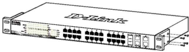
Then, use the screws provided with the equipment rack to mount the switch in the rack.
Figure 3. Installing the switch in a standard-sized equipment rack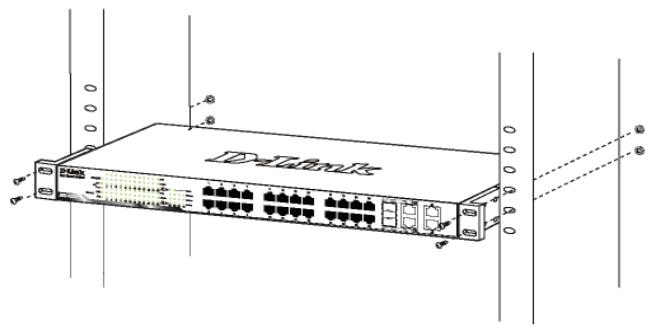
Step 3 – Plugging in the AC Power Cord
You can now connect the AC power cord into the rear of the switch and to an electrical outlet (preferably one that is grounded and surge protected).
Figure 4. Plugging the switch into an outlet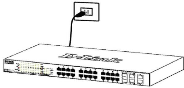
Power Failure
As a precaution, the switch should be unplugged in case of power failure. When power is resumed, plug the switch back in.
Management Options
The D-Link Web Smart Switch can be managed in-band by using Telnet. The user may also choose the Web-based Management, accessible through a web browser or through any PC using the SmartConsole Utility.
If you want to manage only one D-Link Web Smart Switch, the Web-Based Management is the better option. Each switch must be assigned its own IP Address, which is used for communication with Web-Based Management or an SNMP network manager and the PC should have an IP address in the same range as the switch.
However, if you want to manage multiple D-Link Web Smart Switches, the SmartConsole Utility is the better option. Using the SmartConsole Utility, you don't need to change the IP address of your PC and it is easy to start the initial setting of multiple Smart Switches. Please refer to the following detailed installation instructions for the Web-Based Management, SmartConsole Utility, Telnet Management and SNMP-Based Management.
Web-based Management Interface
After a successful physical installation, you can configure the switch, monitor the LED panel, and display statistics graphically using a web browser, such as Netscape Navigator (version 6.2 and higher) or Microsoft Internet Explorer (version 5.0 and higher).
You need the following equipment to begin the web configuration of your device:
A PC with a RJ-45 Ethernet connection A standard Ethernet cable
Step 1
Connect the Ethernet cable to any of the ports on the front panel of the switch and to the Ethernet port on the PC.
Figure 6. Connected Ethernet cable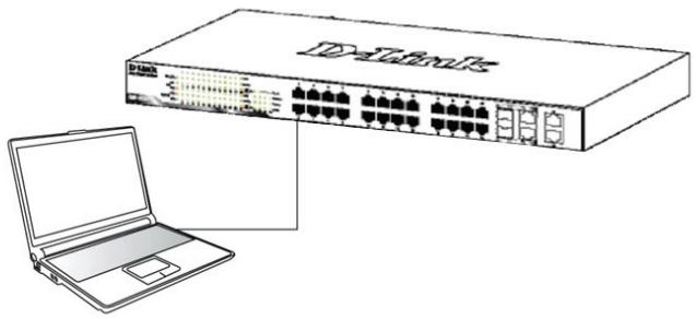
Step 2
In order to login and configure the switch via an Ethernet connection, the PC must have an IP address in the same range as the switch. For example, if the switch has an IP address of 10.90.90.90, the PC should have an IP address of 10.x.y.z (where x/y is a number between 0 ~ 254 and z is a number between 1 ~254), and a subnet mask of 255.0.0.0.
Open your web browser and enter http://10.90.90.90 (the factory-default IP address) in the address box. Then press .
Figure 7. Enter the IP address 10.90.90.90 in the web browser
The web configuration can also be accessed through the SmartConsole Utility. Open the SmartConsole Utility and double-click the switch as it appears in the Device List. This will automatically load the web configuration in your web browser.

NOTE: The switch's factory default IP address is 10.90.90.90 with a subnet mask of 255.0.0.0 and a default gateway of 0.0.0.0
Step 3
When the following logon box appears, enter "admin" for the password. Press OK to enter the main configuration window.
Figure 8. User authentication window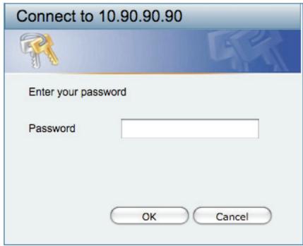
Step 4
Before entering the Web-based Management, the Smart Wizard will guide you to quickly configure some functions, such as Password Settings, SNMP Settings, and System Settings. If you don't plan to change anything, click Exit to exit the Wizard and enter the Web-based Management. For a detailed look at the Smart Wizard's functions, please refer to the Smart Wizard introduction in the user manual.
SmartConsole Utility
The SmartConsole Utility included on the installation CD is a program for discovering Smart Switches with the same L2 network segment connected to your PC. This tool is only for computers running Windows 2000, Windows XP, and Windows Vista x64/86 operating systems. There are two options for the installation of SmartConsole Utility, one is through the autorun program on the installation CD and the other is manual installation.
Note: Please be sure to remove any existing SmartConsole Utility from your PC before installing the latest SmartConsole Utility.
Option 1: Follow these steps to install the SmartConsole Utility via the autorun program on the installation CD.
- Insert the Utility CD into your CD-ROM drive.
- The autorun program will pop up automatically.
- Simply click on the "Install SmartConsole Utility" button and an installation wizard will guide you through the process.
- After successfully installing the SmartConsole Utility, you can open the utility by clicking Start > Programs > D-Link SmartConsole Utility.
- Just connect the Smart Switch to the same L2 network segment of your PC and use the SmartConsole Utility to discover the Smart Switches.
Option 2: Follow these steps to install the SmartConsole Utility manually.
- Insert the Utility CD into your CD-ROM drive.
- From the Start menu on the Windows desktop, choose Run.
- In the Run dialog box, type D:\D-Link SmartConsole Utility\setup.exe (where D:\ represents the drive letter of your CD-ROM) and click OK.
- Follow the on-screen instructions to install the utility.
- Upon completion, go to Start > Programs > D-Link SmartConsole Utility and open the SmartConsole Utility.
- Just connect the Smart Switch to the same L2 network segment of your PC and use the SmartConsole Utility to discover the Smart Switches.
For a detailed look at SmartConsole's functions, please refer to the SmartConsole Utility introduction in the user manual.
Telnet Management
Users may also access the switch through Telnet using your PC's Command Prompt. To access it from your computer, users must first ensure that a valid connection is made through the Ethernet port of the Switch and your PC, and then click Start > Programs > Accessories > Command Prompt on your computer. Once the console window opens, enter the command telnet 10.90.90.90 (depending on configured IP address) and press Enter on your keyboard. You should be directed to the opening console screen for the Command Line Interface of the switch, enter the "admin" for the default user name and password for the Switch and press the Enter key.
SNMP-Based Management
You can manage the Switch with D-Link D-View or any SNMP-compatible program. The SNMP function is default Disabled for D-Link Web Smart switches.
Additional Information
If you are encountering problems setting up your network, please refer to the user manual that came with the switch. It contains many more rules, charts, explanations, and examples to help you get your network up and running.
Additional help is available through our offices listed at the back of the user manual or online. To find out more about D-Link products or marketing information, please visit the website http://www.dlink.com.tw; for any support issue, please visit the website http://support.dlink.com.tw, which will re-direct you to appropriate local D-Link website.
Notes
SmartConsole Utility
Connect the power cable to the power outlet (preferably grounded and protected by a circuit breaker).
Figure 4. Connecting the switch to the outlet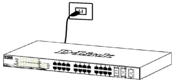
Power failure
In case of a power failure, the switch should be turned off. When power is restored, turn it on again.
Control functions
The D-Link Web Smart switch can be controlled using the Telnet protocol. You can also choose control via a web interface, accessible through a web browser or from any computer using the SmartConsole utility.
If you need to control only one D-Link Web Smart switch, the Web-Based Management Utility is the best choice. Each switch must have its own IP address, which you use for communication with the Web-Based Management Utility or with the SNMP management manager. The computer must have an IP address from the same range as the switch.
However, if you need to control multiple D-Link Web Smart switches, the SmartConsole Utility is the best choice. With the SmartConsole Utility, you do not need to change the IP address of the computer, and with its help you can easily start configuring several Web Smart series switches. Please refer to the following detailed installation instructions for Web-Based Management Utility and SmartConsole Utility, control via Telnet and SNMP.
Web-based management
Figure 8. User authentication window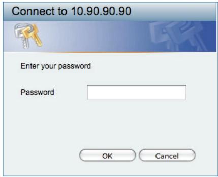
Step 4
In the Web-based Management menu, using the Smart Wizard setup wizard, perform a quick configuration of several functions, such as Password Settings, SNMP Settings, and System Settings. If you do not need to change these settings, press Exit to leave the setup wizard and return to the Web-based Management menu. For more detailed information about the functions of the setup wizard, please refer to the corresponding section of the user manual.
SmartConsole Utility
The SmartConsole Utility, included on the installation CD, is a program for detecting Smart switches in one network segment of level 2, connected to the computer. This utility can be installed only on computers running the following operating systems: Windows 2000, Windows XP, and Windows Vista x64/86. There are two installation options for the SmartConsole Utility: the first is through the autorun program on the installation CD, and the second is manual installation.
SmartConsole Utility
SmartConsole Utility
SmartConsole Utility
sabneotmssk:255.0.0.0
一ト工:0.0.0
Stépp3


- GETTING STARTED GUIDE FOR D-LINK WEB SMART SWITCH
- ABOUT THIS GUIDE
- STEP 1 – UNPACKING
- STEP 2 - SWITCH INSTALLATION
- DESKTOP OR SHELF INSTALLATION
- RACK INSTALLATION
- STEP 3 – PLUGGING IN THE AC POWER CORD
- POWER FAILURE
- MANAGEMENT OPTIONS
- WEB-BASED MANAGEMENT INTERFACE
- STEP 1
- STEP 2
- STEP 3
- STEP 4
- SMARTCONSOLE UTILITY
- OPTION 1: FOLLOW THESE STEPS TO INSTALL THE SMARTCONSOLE UTILITY VIA THE AUTORUN PROGRAM ON THE INSTALLATION CD
- OPTION 2: FOLLOW THESE STEPS TO INSTALL THE SMARTCONSOLE UTILITY MANUALLY
- TELNET MANAGEMENT
- SNMP-BASED MANAGEMENT
- ADDITIONAL INFORMATION
- NOTES
- CONTROL FUNCTIONS
- WEB-BASED MANAGEMENT
- STÉPP3
Brand : D-LINK
Model : WEB SMART SWITCH
Category : Network switch