
FILTRA VACS - Industrial Vacuums NILFISK - Free user manual and instructions
Find the device manual for free FILTRA VACS NILFISK in PDF.

| Product type | Industrial vacuum cleaner |
| Brand | NILFISK |
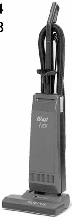
| Model | FILTRA VACS (Filtra Vac 14 / Filtra Vac 18) |
| Power supply | 230 V, 50 Hz, 1000 W |
| Max. air flow | 120 m³/h |
| Max. vacuum | 18 000 Pa |
| Noise level | 68 dB(A) at 1 m |
| Power cord length | 12 m |
| Protection class | II |
| Protection type | IP X4 (protected against water splashes) |
| Width | 356 mm (Filtra Vac 14) / 457 mm (Filtra Vac 18) |
| Depth | 229 mm |
| Height | 1041 mm |
| Weight | 8 kg (Filtra Vac 14) / 9 kg (Filtra Vac 18) |
| Suction type | Dry only |
| Main functions | Motorized brush, suction power adjustment, full bag indicator, brush overload protection |
| Routine maintenance | Bag change, motor filter and micro-filter replacement, belt and brush replacement |
| Safety | 30 mA differential circuit breaker recommended, automatic overload shutdown, tank lock |
| Spare parts | Dust bags (ref. 64895), microfilter, motor filter, belt, brush |
| Country of origin | Germany |
Frequently Asked Questions - FILTRA VACS NILFISK
User questions about FILTRA VACS NILFISK
0 question about this device. Answer the ones you know or ask your own.
Ask a new question about this device
Download the instructions for your Industrial Vacuums in PDF format for free! Find your manual FILTRA VACS - NILFISK and take your electronic device back in hand. On this page are published all the documents necessary for the use of your device. FILTRA VACS by NILFISK.
USER MANUAL FILTRA VACS NILFISK
Total Cleaning Confidence
Wichtige Sicherheitschinweise 2
GB Important safety notes. 4
F Consignes de sécurité importantes 6
NL Belangrijke veiligheidsinstrukties 8
① Avvertenze importanti per la sicurezza ... 10
BRAND-BZW. EXPLOSIONSGEFAHR
Before putting the cleaner into operation, be sure to also read the enclosed operating instructions thoroughly and keep them close at hand for future reference.
The cleaner may only be used by persons trained in its use and expressly authorised to use it.
GENERAL
Operation of this cleaner is subject to the applicable national regulations.
In addition to these operating instructions and the binding regulations on accident prevention applicable in the country of use, the generally acknowledged technical rules for safe and correct working must also be observed.
Any method of work endangering health or safety is forbidden!
HEALTH-ENDANGERING DUSTS*)
This cleaner is not suitable for picking up health-endangered dusts.
FIRE AND EXPLOSION HAZARD


The following materials must not be picked up with the cleaner:
Hot materials (glowing cigarettes, hot ashes, etc.)
Inflammable, explosive or aggressive fluids (e.g. petrol, solvents, acids, alkalines, etc.)
Inflammable, explosive dusts (e.g. magnesium or aluminium dust, etc.).
APPLIANCE PLUG SOCKET
Before connecting any appliance to the appliance plug socket, the cleaner must always be switched off.
If appliances are connected to the appliance plug socket, ensure that these appliances are also switched off when being connected to the appliance plug socket.
CAUTION!
The operating instructions and the safety precautions contained therein must be observed when using appliances connected to the appliance plug socket of the cleaner.
USING FOR THE FIRST TIME
Before using the cleaner for the first time, check that it is in a good and safe condition.
Plugs and connectors of mains leads must be at least splash water-proof.
Check the mains connection and mains plug.
Inspect the mains lead at regular intervals for damage or signs of ageing. Use the cleaner only when the mains lead is in a good and safe condition.
(Damaged mains leads present a danger of electric shocks!)
Use the cleaner only with an undamaged filter element.
DURING OPERATION
Take care not to damage the mains lead (e.g. by driving over, pinching or dragging). Pull out the mains plug only directly at the plug, i.e. not by pulling at the mains lead.
Before picking up liquids, the filter bag must be removed and the function of the float switch checked. If foaming is observed, stop work immediately and empty the tank.
MAINTENANCE AND REPAIR
CAUTION!
Before cleaning and servicing the cleaner, always remove the mains plug.
Carry out only maintenance operations described in these operating instructions. Use only original Wap spare parts.
Do not make any technical modifications to the cleaner.
CAUTION!
Your safety could be endangered as a result!
For all other maintenance and repair work, please contact the Wap Service department or an authorised specialist workshop!
ELECTRICAL EQUIPMENT
Check the rated voltage of the cleaner before connecting it to the mains power supply. Ensure that the voltage specified on the rating plate corresponds to the local mains voltage.
When connected to the mains power supply with a mains lead of type H 07 RN-F 3G 1.5 mm², the cleaner may also be used outdoors.
When using an extension lead or replacing the mains lead, the lead type specified by the manufacturer must always be used.
We recommend that the power supply to the cleaner be connected via an earth-leakage circuit breaker which interrupts the power supply either if the earth leakage current exceeds 30mA for 30 ms, or it contains an earthing test current circuit.
When using an extension lead, observe the minimum cross-sections of the leads:
| Cable length m | Cross-section mm2 |
| up to 20 | 1.5 |
| 20 to 50 | 2.5 |
Always arrange the current-carrying parts (plug sockets, plugs and connectors) and lay extension leads so that the protection class of the cleaner is maintained.
CAUTION!
Never spray the top section of the cleaner with water: Danger for persons, danger of short circuits.
The latest edition of the IEC Regulations must be observed.

POUR VOTRE PROPRESÉCURITÉ
FOR APPARATET TAS I BRUK
VEDLIKEHOLD OG REPARASJON
OBS!
För rengjöring og vedlikehold av støvsugeren ma stöpselet alltid frakopies stikkontakten.
KONSERWACJA I NAPRAWY
Incentive International A/S
Kongens Nytorv 28
P.O.Box 2064
1013 Copenhagen K
Tel.: +45 33 11 11 42
Fax: +45 33 93 46 36
E-mail: incentive@incentive-dk.com
SUBSIDIARIES
AUSTRALIA
ALTO Overseas Inc.
1B/8 Resolution Drive
P.O.Box 797
Caringbah, N.S.W. 2229
Tel.: +61 295 24 61 22
Fax: +61 295 24 52 56
AUSTRIA
24 Constellation Road
Rexdale
Ontario M9W 1K1
Tel.: +1 416 6 75 58 30
Fax: +1 416 6 75 69 89
CROATIA
Wap ALTO Strojevi za ciscenje, d.o.o.
Siget 18a
10020 Zagreb
Tel.: +385 16554144
Fax: +385 165 54 112
E-mail: admin.wap@wap-sistemi.hr
CZECH REPUBLIC
ALTO Cleaning Systems
(UK) Ltd.
Bowerbank Way
Gilwilly Industrial Estate, Penrith
Cumbria CA11 9BN
Tel.: +44 1 7 68 86 89 95
Fax: +44 1 7 68 86 47 13
E-mail: sales@alto-uk.com
JAPAN
Representative Office
5-2, Sakyo 1-Chome
631-0801 Nara City
ALTO Cleaning Systems, Inc.
12249 Nations Ford Road
28134 Pineville
Tel.: +1 704 971 1240
Fax:+17049711241
E-mail: info@altocsi.com
ALTO U.S. Inc.
16253 Swingley Ridge Road, Suite 200
63017-1544 Chesterfield, Missouri
Tel.: +1 636 530 0871
Fax: +1 636 530 0872
E-mail: info@alto-us.com
ALTO U.S. Inc.
2100 Highway 265
72764 Springdale, Arkansas
Tel.: +1 479 750 1000
Fax: +1 479 756 0719
E-mail: info@alto-us.com
ALTO U.S. Inc.
1100 Haskins Road
43402 Bowling Green
Tel.: +1 419 352 7
Fax:+14193537187
E-mail: info@alto-us.com
Filtr Vac 14
Filtr Vac 18

ALTO
Betriebsanleitung. 2
Operating Instructions.....7
Instructions de Service..... 12
NL Gebruiksaanwijzing 17
① Istruzioni sull'uso 22
N Driftsinstruks 27
⑤ Bruksanvising 32
DK Driftsvejledning 37
Käyttoohje 42
SLO Navodilo za uporabo 47
HR Uputstvo za rad 52
SK Prevádkový námod 57
Provozní námod 62
PL Instrukcja obstugi 67
Kezelésiutasités 72
E Instrucciones de manejo.. 77
Instruções de operação.... 82
GR Odbnyiec IeitoupyiaC 87
TR Isletme kilavuzu 92
1
2
3
4
5
6
7
8
9
10
11
12

- The use of filter bags, motor protection filters and micro exhaust air filters is necessary for the proper function of the cleaner.
- Observe the filter change indicator, check all filters and clean or replace as described in the operating instructions.
- This combination cleaner is not an appliance to be used by children.
- This cleaner is not suitable for picking up health-endangered dusts.
- Repairs may only be carried out by qualified persons using only original Alto spare parts. Unqualified repairs to the cleaner represent a danger for the user.
Before all maintenance operations, cleaning, filter changes and after use, switch off the cleaner and remove the mains plug!
- Never point nozzles and/or tube ends at eyes or ears.
- The cleaner is only to be used for dry cleaning - not for picking up liquids or for cleaning outdoors.
- Humans and animals must not be cleaned with the cleaner. The manufacturer accepts no liability for any damage or injury arising from any unintended use or incorrect operation.
- Do not pick up hot or glowing/smouldering materials.
- Do pick up coarse broken glass.
- Do not pick up solvents, explosive fluids or gases.
- Do not store the cleaner outdoors.
- Do not expose the cleaner to the weather, to moisture or to direct sources of heat.
Clean the cleaner only dry or with a slightly damp cloth. The electrical parts (switches, plug, plug socket, electronics, etc.) must not be allowed to come into contact with water.
DISPOSAL INSTRUCTIONS
Do not simply throw away the cleaner packaging, the full filters and later the cleaner when no longer serviceable. Dispose of everything in accordance with the guidelines laid down by the local authority or the responsible waste disposal company.
- Dispose of the packaging materials separately according to material types in the containers provided for their collection so that they can be recycled.
- When the cleaner can no longer be used, make it unserviceable immediately and take to the appropriate collection point for old appliances.
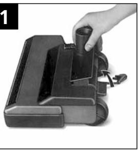
ASSEMBLY
Push the swivel joint forward until it engages. (Fig. 1)
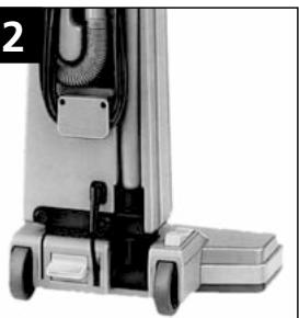
SECURING THE TANK (Fig. 2)
Place the suction unit onto the swivel joint. Secure the suction unit with the two star-head bolts supplied.
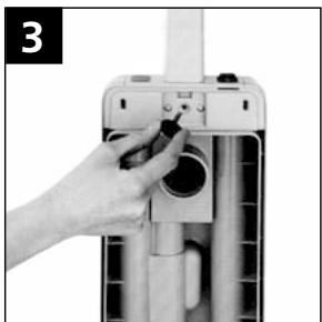
SECURING THE HANDLE (Fig. 3)
Pull up the grip on the tank and remove the cover. Push the holder for the crevice nozzle onto the handle. Secure the handle to the tank with the star-head bolt.
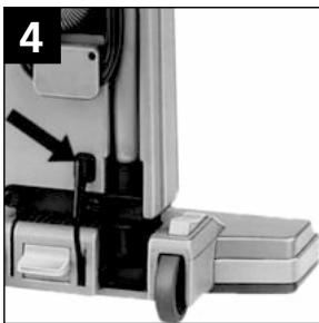
CONNECTING THE FLOOR BRUSH (Fig. 4)
Insert the plug of the floor brush power cable into the plug socket on the suction unit.
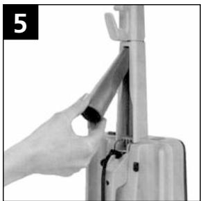
ATTACHING ACCESSORIES
Push the crevice nozzle into the holder on the rear and the universal nozzle onto the nozzle holder on the front of the guide tube (Fig. 5).
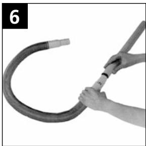
ASSEMBLING THE ACCESSORIES
The flexible suction hose has two different connectors (1 hand tube with suction force controller, 1 hose connector). Push the extension onto the hand tube with the suction force controller (Fig. 6).
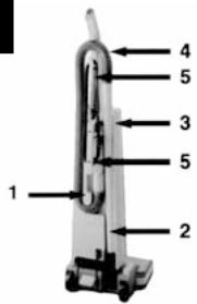
COMPLETING THE CLEANER (Fig. 7)
1 =Push the mounting onto the suction unit and press the suction hose into the guide on the rear of the suction unit.
2 = Press the extension tube into the 3 = guide on the rear of the suction unit.
4 = Press the suction hose into the holder above the swivelling cable holder.
5 = Wrap the mains lead around the swivelling cable holder (Fig. 2)
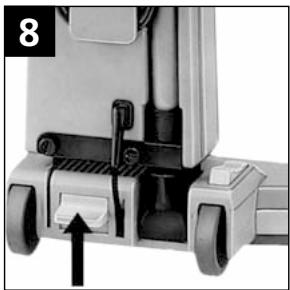
TILTING THE HANDLE (Fig. 8)
Press the pedal down with your foot and tilt the handle.
Please note: The floor brush is switched off when the cleaner is upright and when the extension tube is removed. When the extension tube is fitted again, it must engage correctly otherwise the floor brush will remain switched off.
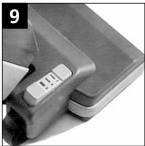
PILE FINE ADJUSTMENT(Fig.9)
Three pile fine
adjustments allow
individual adaption to
extreme carpet surfaces
and to hard floor
coverings.
Normal floor coverings Loop pile carpets High-pile carpets
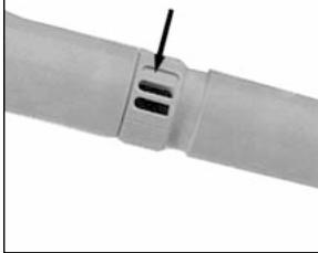
SUCTION FORCE CONTROL (Fig. 10)
The suction force controller on the hand tube allows the desired suction force at the nozzle to be adjusted.
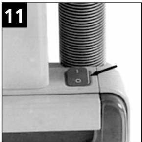
SWITCHING ON AND OFF (Fig. 11)
Actuate the switch to turn the cleaner ON and OFF. Position "I" ON Position "O" OFF
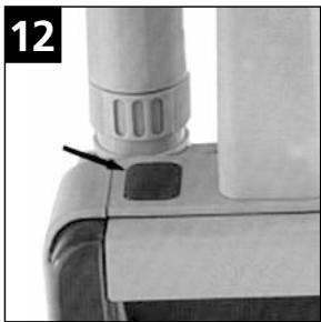
FILTER CHANGE INDICATOR (Fig. 12)
The red lamp of the electric filter change indicator lights up when the filter bag has to be changed or when the suction channel is clogged.
The filter change indicator evaluates the air permeability of the twinply filter bag.
Filter bag empty: No reaction of the indicator (high air permeability)
Filter bag full: The filter change indicator lights up (filter bag not permeable to air) The filter bag has to be replaced.
Please note that when picking up cement, plaster or extremely fine dusts, the air permeability of the filter bag can be impaired to such an extent that the filter
change indicator lights up although the filter bag is still relatively empty. In this case the filter bag has to be replaced because otherwise the suction power will be excessively reduced. If the filter change indicator remains lit even after changing the filter bag, the suction channel (tube, nozzles, suction hose, hose fitting or filter bag) is clogged. After clearing the clogging, the red indicator light goes out.
MAINTENANCE
Before maintenance and repair work, remove the mains plug from the plug socket!
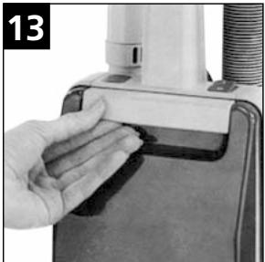
OPENING THE SUCTION UNIT (Fig. 13)
Pull up the grip on the tank and remove the cover.
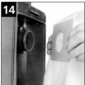
INSERTING THE FILTER BAG (Fig. 14)
Push the filter bag with the reinforcing sleeve onto the fitting of the suction tank. The tank can only be closed when a filter bag has been fitted.
Please use original filter bags as these are optimally designed for the function of the cleaner.
No claim under warranty will be accepted for any damage resulting from the use of filter bags of other brands.
Filter bags can be reordered under the Order No. 64895.
One pack contains:
5 filter bags
1 micro exhaust air filter
2 motor protection filters
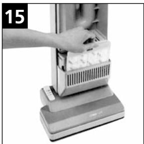
REPLACING THE MICRO EXHAUST AIR FILTER (Fig.15)
When the filter bag has been changed 5 times, the micro exhaust air filter must also be changed: Open the tank and pull the filter cassette upwards out of the guide.
Open the cassette and replace the micro exhaust air filter, close the cassette again and push into the guide up to the stop.


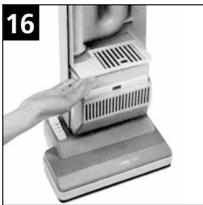
REPLACING THE MOTOR PROTECTION FILTER (Fig. 16)
When the filter bag has been changed 5 times or in the event of extreme soiling, the motor protection filter must also be changed: Open the tank and pull the filter cassette out of the guide to the front. Open the cassette and replace the motor protection filter, close the cassette again and push into the guide up to the stop.
CLEANING THE CLEANER
Remove the mains plug from the plug socket. Clean the cleaner only dry or with a damp cloth. Never immerse in water. The filter chamber should also be cleaned with a damp cloth, when necessary.
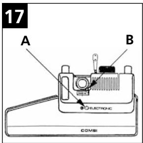
ELECTRONIC BRUSH AND SUCTION CONTROL
The cleaner is equipped with an electronic overload protection device (Fig. 17 B).
The overload protection device trips if the brush motor is overloaded. In this case the red blocking indicator lights up. (Fig. 17 A).
Remove the mains plug from the plug socket, determine and eliminate the cause of the overload. Tilt the fixed tank and press in the knob of the overload protection device on the motor hood. The machine is now ready for operation again.
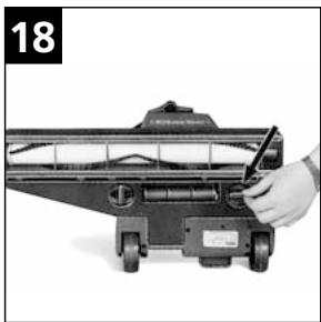
REPLACING THE TOOTHED BELTS AND BRUSH ROLLER
Caution: Remove the mains plug from the plug socket!
Position the locking bolts in a horizontal position before removing the baseplate. (Fig. 18).
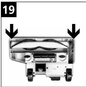
Remove the brush roller from the floor brush. Fit the new toothed belts, thread the brush roller through the flat belt and pull forward until the bearings can be inserted into the housing guide (Fig. 19).
When inserting the bearings, ensure that
both have the same mark.
I = Cam for new brush roller
II = Cam for partly worn brush roller
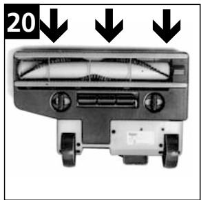
Fit and lock the baseplate, ensuring that the retaining caps of the baseplate engage on the front edge of the housing (Fig. 20).
| Voltage | Volt | 230 |
| Mains frequency | Hz | 50 |
| Power consumption | Watt | 100 |
| Filtra Vac 14 | Filtra Vac 18 | ||
| Volumetric flow (air) | max. m³/h | 120 | 120 |
| Vacuum | max. Pa | 18000 | 18000 |
| Sound pressure level at a distance of 1 m from the machine to DIN 45635, Part 1 (4/84) in the free field at full volumetric flow | dB(A) | 68 | 68 |
| Mains lead | m | 12 | 12 |
| Protection class | II | II | |
| Type of protection (splash water-proof) | IP X4 | IP X4 | |
| Interference suppression level | EN 50014 | EN 50014 | |
| Width | mm | 356 | 457 |
| Depth | mm | 229 | 229 |
| Height | mm | 1041 | 1041 |
| Weight | kg | 8 | 9 |

PRIÈRE DE LIRE LA NOTICE D'UTILISATION ET D'OBSERVER LES CONSIGNES DE SECURITÉ!
CONSIGNES DE SÉCURITÉ
INDICATIONS RELATIVES A L'EVACUATION DES DÉCHETS
REplacement DU MICROFILTRE D'AIRD'EVACUATION (Fig.15)
ANSLUTA GOLVSUGBORSTEN (Bld 4)
MONTAGE AF BEHOLDEREN (III. 2)
KLARGØRING AF APPARATET (III. 7)
RENSNING AF APPARATET
POKNY TYKAJICI SE BEZPECNOSTI
KOMPLETACE PRIXSTROJE (Sika 7)
1 = upinaci prvek nasunte na saci jegnotku a saci hadici vtlacte do vodici drážky na zadni strané saci jegnotky.
2 = prodlužovaci trabku
vtračte do 3 = vodici
držky na zadni stranje
saci Jednotky
PRESNÉ NASTAVENI VLASU KOBERCE (Sika 9)
Poloha "I" = zapnout
Poloha "0" = vypnout
INDIKACE VYMENY FILTRU (Slika 12)
CIHAZIN TAMAMLANMASI (RES. 7)
HAV HASSAS AYARI (RES.9)
EMME GUCU AYARI (RES. 10)
EU Declaration of Conformity
Carpet-Brushing Vacuum Cleaner
Product:
Filtra Vac 14 / Filtra Vac 18
Type:
220-230 V\~, 50 Hz, 1000 W
Description:
EC Machine Directive 98/37/EG
The design of the unit corresponds to the following pertinent information:
EC Low-voltage Directive
73/23/EG
EC EMV Directive
89/336/EG
Applied harmonised standards:
EN 292
EN 60335-1, EN 60335-2-69
EN 55014-1, EN 55014-2, EN 61000-3-2
Applied national standards and technical specifications:
390 South Woods Mill Road
Suite 300
Chesterfield
USA-Missouri 63017-3433
1B/8 Resolution Drive
P.O.Box 797
AUS-Caringbah, N.S.W. 2229
Tel: (+ + 61) 295246122
Fax: (++61) 295 24 52 56
AUSTRIA
24 Constellation Road
Rexdale
C-Ontario M9W 1K1
Tel: 14166755830
Fax:14166756989
CZECHIA
Gilwilly Industrial Estate
GB-Penrith, Cumbria CA11 9BN
Tel: (+44) 1768868995
Fax: (+44) 1768864713
Telex: 64309 kewg
ASIA
Alto Hong Kong
Representative Office
RM 602, Tower B, Regent Ctr.
70, Ta Chuen Ping Street
Kwai chung
HK-Hong Kong
Tel. (+ + 852) 26101042
Fax (+ + 852) 26101047
JAPAN
Representative Office
Naruse-build 4F
7-2 Shinbashi 1-Chome, Minato-Ku
J-Tokyo 105-004
Tel: (+81) 3 35 69 38 07
Fax: (+81) 335693808
Wap Representative Office Japan
25-6, Honode Cho
Adachi-Ku
J-Tokyo-120-0021
Tel. (+81) 3/52440782
Fax (+81) 3/52440783
KROATIA
Wap systemdi za eiseaegenje, d.o.o.
HR-10000 Zagreb
Florijana Andrašeca 14
Tel. (+ + 385) 01/3094907
(++385)01 / 3094909
Fax (+ + 385) 01/3094906
NETHERLANDS
Representative Office
271 Bukit Timah Road
04-11 Balmoral Plaza
SG-Singapore 259708
Tel: (+65) 8366455
Fax: (+65) 8366456
SLOWAKIA
Wap éistace systémy spel. s.r.o.
SK-83237 Bratislava
Vajnorska 135
Tel. (+ + 421) 744259664
Fax (+ + 421) 744257944
SLOWENIA
Wap eistilni sistemi, d.o.o.
SLO-1110 Ljubljana
Letalisha 33
Tel. (+ + 0368) 61442342
Fax (+ + 0368) 611404294
SOUTH AFRICA
Wap South Africa (Pty) Ltd.
ZA-Kempton Park (T) 1620
P.O.Box 2122
Tel. (+ + 27) 119757060
Fax (+ + 27) 113943081
SPAIN
Hidrolimpia, S.L.
E-28760 Tres Cantos - Madrid
1500 North Belcher Road
Clearwater
USA-Florida 33765
Tel: (+1) 72 74 61 45 55
Fax: (+1) 72 74 61 51 93
- BRAND-BZW. EXPLOSIONSGEFAHR
- GENERAL
- HEALTH-ENDANGERING DUSTS*)
- FIRE AND EXPLOSION HAZARD
- APPLIANCE PLUG SOCKET
- CAUTION!
- USING FOR THE FIRST TIME
- (Damaged mains leads present a danger of electric shocks!)
- DURING OPERATION
- MAINTENANCE AND REPAIR
- ELECTRICAL EQUIPMENT
- POUR VOTRE PROPRESÉCURITÉ
- FOR APPARATET TAS I BRUK
- VEDLIKEHOLD OG REPARASJON
- KONSERWACJA I NAPRAWY
- SUBSIDIARIES
- AUSTRALIA
- AUSTRIA
- CROATIA
- CZECH REPUBLIC
- JAPAN
- Filtr Vac 14
- Filtr Vac 18
- DISPOSAL INSTRUCTIONS
- ASSEMBLY
- SECURING THE TANK (Fig. 2)
- SECURING THE HANDLE (Fig. 3)
- CONNECTING THE FLOOR BRUSH (Fig. 4)
- ATTACHING ACCESSORIES
- ASSEMBLING THE ACCESSORIES
- COMPLETING THE CLEANER (Fig. 7)
- TILTING THE HANDLE (Fig. 8)
- PILE FINE ADJUSTMENT(Fig.9)
- SUCTION FORCE CONTROL (Fig. 10)
- SWITCHING ON AND OFF (Fig. 11)
- FILTER CHANGE INDICATOR (Fig. 12)
- MAINTENANCE
- REPLACING THE MOTOR PROTECTION FILTER (Fig. 16)
- CLEANING THE CLEANER
- ELECTRONIC BRUSH AND SUCTION CONTROL
- REPLACING THE TOOTHED BELTS AND BRUSH ROLLER
- Caution: Remove the mains plug from the plug socket!
- PRIÈRE DE LIRE LA NOTICE D'UTILISATION ET D'OBSERVER LES CONSIGNES DE SECURITÉ!
- CONSIGNES DE SÉCURITÉ
- INDICATIONS RELATIVES A L'EVACUATION DES DÉCHETS
- REplacement DU MICROFILTRE D'AIRD'EVACUATION (Fig.15)
- ANSLUTA GOLVSUGBORSTEN (Bld 4)
- MONTAGE AF BEHOLDEREN (III. 2)
- KLARGØRING AF APPARATET (III. 7)
- RENSNING AF APPARATET
- POKNY TYKAJICI SE BEZPECNOSTI
- KOMPLETACE PRIXSTROJE (Sika 7)
- PRESNÉ NASTAVENI VLASU KOBERCE (Sika 9)
- INDIKACE VYMENY FILTRU (Slika 12)
- CIHAZIN TAMAMLANMASI (RES. 7)
- HAV HASSAS AYARI (RES.9)
- EMME GUCU AYARI (RES. 10)
- EU Declaration of Conformity
- CZECHIA
- ASIA
- KROATIA
- NETHERLANDS
- SLOWAKIA
- SLOWENIA
- SOUTH AFRICA
- SPAIN
Brand : NILFISK
Model : FILTRA VACS
Category : Industrial Vacuums