BR 600S - Scrubber NILFISK - Free user manual and instructions
Find the device manual for free BR 600S NILFISK in PDF.

| Product type | Ride-on scrubber dryer |
| Brand | NILFISK |
| Model | BR 600S |
| Dimensions (L x W x H) | 1350 x 630 x 1050 mm |
| Weight (with batteries) | 400 kg |
| Power supply | 24 V battery |
| Solution tank capacity | 85 L |
| Recovery tank capacity | 95 L |
| Cleaning width | 600 mm |
| Drying width | 850 mm |
| Working speed | 0-5 km/h |
| Maximum working area | 2200 m²/h |
| Maximum slope | 5 % |
| Brush system | 2 cylindrical brushes |
| Filter type | Water filter (float) |
| Safety | Hand brake, circuit breaker, ignition key |
| Maintenance | Regular tank cleaning, brush inspection, tank drainage |
| Spare parts | Brushes, filters, squeegee blades |
| Usage | Hard floors (tile, PVC, etc.) |
| Noise level | < 70 dB(A) |
Frequently Asked Questions - BR 600S NILFISK
User questions about BR 600S NILFISK
0 question about this device. Answer the ones you know or ask your own.
Ask a new question about this device
Download the instructions for your Scrubber in PDF format for free! Find your manual BR 600S - NILFISK and take your electronic device back in hand. On this page are published all the documents necessary for the use of your device. BR 600S by NILFISK.
USER MANUAL BR 600S NILFISK
natural_image
Technical line drawing of a cleaning or inspection device with internal components (no text or symbols)
Instructions For Use Instrucciones de uso
Advance MODELS 56314000(2400D), 56314001(2600D), 56314002(2810D), 56314003(3210D)
56314004(2400C), 56314005(2600C), 56314006(2810C), 56314007(3210C)
56314992(2810D-AXP), 56314993(3210D-AXP), 56314994(2810C-AXP), 56314995(3210C-AXP)
Nilfisk MODELS 56314010(600S), 56314011(650S), 56314012(700S), 56314013(800S)
56314014(600SC), 56314015(650SC), 56314016(700SC), 56314017(800SC)
56316517(600S EDS), 56314996(700S EDS), 56314997(800S EDS)
56316518(600SC EDS), 56314998(700SC EDS), 56314999(800SC EDS)
TABLE OF CONTENTS
page
Introduction......A-2
Cautions and Warnings ...... A-3
Prepare the Machine for Use
Install the Batteries....A-7
Install the Brushes....A-8
Install the Squeegee....A-9
Fill the Solution Tank ...... A-9
Detergent (AXP™/EDS™) System....A-10 – A-11
Operating the Machine ...... A-12
Scrubbing ...... A-12
Wet Vacuuming ...... A-12
After Use....A-13
Maintenance Schedule....A-13
Lubricating the Machine ...... A-13
Charging the Batteries....A-14
Check the Battery Electrolyte Level....A-14
Squeegee Maintenance....A-15
Squeegee Adjustment ...... A-15
Side Skirt Maintenance....A-16 – A-17
Troubleshooting....A-18
Technical Specifications ...... A-19
INTRODUCTION
This manual will help you get the most from your Nilfisk-Advance Rider Scrubber. Read it thoroughly before operating the machine.
Note: Bold numbers in parentheses indicate an item illustrated on pages A-5 – A-6.
This product is intended for commercial use only.
PARTS AND SERVICE
Repairs, when required, should be performed by your Authorized Nilfisk-Advance Service Center, who employs factory trained service personnel, and maintains an inventory of Nilfisk-Advance original replacement parts and accessories.
Call the NILFISK-ADVANCE DEALER named below for repair parts or service. Please specify the Model and Serial Number when discussing your machine.
(Dealer, affix service sticker here.)
NAME PLATE
The Model Number and Serial Number of your machine are shown on the Nameplate on the machine. This information is needed when ordering repair parts for the machine. Use the space below to note the Model Number and Serial Number of your machine for future reference.
MODEL NUMBER ____
SERIAL NUMBER ____
UNCRATE THE MACHINE
When the machine is delivered, carefully inspect the shipping carton and the machine for damage. If damage is evident, save the shipping carton so that it can be inspected. Contact the Nilfisk-Advance Customer Service Department immediately to file a freight damage claim.
After removing the carton, cut the plastic straps and remove the wooden blocks next to the wheels. Use a ramp to roll the machine from the pallet to the floor.
CAUTIONS AND WARNINGS
SYMBOLS
Nilfisk-Advance uses the symbols below to signal potentially dangerous conditions. Always read this information carefully and take the necessary steps to protect personnel and property.

DANGER!
Is used to warn of immediate hazards that will cause severe personal injury or death.

WARNING!
Is used to call attention to a situation that could cause severe personal injury.

CAUTION!
Is used to call attention to a situation that could cause minor personal injury or damage to the machine or other property.


Read all instructions before using.
GENERAL SAFETY INSTRUCTIONS
Specific Cautions and Warnings are included to warn you of potential danger of machine damage or bodily harm.

WARNING!
* This machine shall be used only by properly trained and authorized persons.
* While on ramps or inclines, avoid sudden stops when loaded. Avoid abrupt sharp turns. Use low speed down hills. Clean only while ascending (driving up) the ramp.
* Keep sparks, flame and smoking materials away from batteries. Explosive gases are vented during normal operation.
* Charging the batteries produces highly explosive hydrogen gas. Charge batteries only in well-ventilated areas, away from open flame. Do not smoke while charging the batteries.
* Remove all jewelry when working near electrical components.
* Turn the key switch off (O) and disconnect the batteries before servicing electrical components.
* Never work under a machine without safety blocks or stands to support the machine.
* Do not dispense flammable cleaning agents, operate the machine on or near these agents, or operate in areas where flammable liquids exist.
* Do not clean this machine with a pressure washer.
* Only use the brushes provided with the appliance or those specified in the instruction manual. The use of other brushes may impair safety.

CAUTION!
* This machine is not approved for use on public paths or roads.
* This machine is not suitable for picking up hazardous dust.
* Do not use scarifier discs and grinding stones. Nilfisk-Advance will not be held responsible for any damage to floor surfaces caused by scarifiers or grinding stones (can also cause damage to the brush drive system).
* When operating this machine, ensure that third parties, particularly children, are not endangered.
* Before performing any service function, carefully read all instructions pertaining to that function.
* Do not leave the machine unattended without first turning the key switch off (O), removing the key and applying the parking brake.
* Turn the key switch off (O) and remove the key, before changing the brushes, and before opening any access panels.
* Take precautions to prevent hair, jewelry, or loose clothing from becoming caught in moving parts.
* Use caution when moving this machine in below freezing temperature conditions. Any water in the solution, recovery or detergent tanks or in the hose lines could freeze, causing damage to valves and fittings. Flush with windshield washer fluid.
* The batteries must be removed from the machine before the machine is scrapped. The disposal of the batteries should be safely done in accordance with your local environmental regulations.
* Do not use on surfaces having a gradient exceeding that marked on the machine.
* All doors and covers are to be positioned as indicated in the instruction manual before using the machine.
SAVE THESE INSTRUCTIONS
CONSIGNES DE PRUDENCE ET DE SÉCURITÉ SYMBOLES
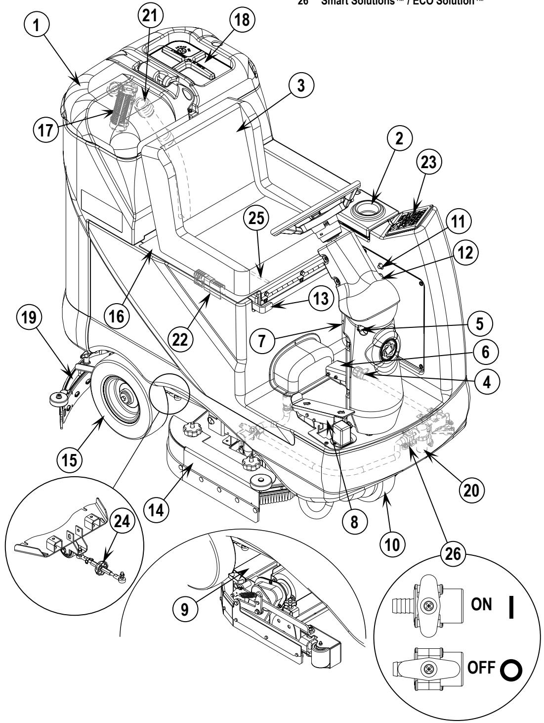
As you read this manual, you will occasionally run across a bold number or letter in parentheses - example: (2). These numbers refer to an item shown on these pages unless otherwise noted. Refer back to these pages whenever necessary to pinpoint the location of an item mentioned in the text. NOTE: Refer to the service manual for detailed explanations of each item illustrated on the next 2 pages.
1 Recovery Tank Cover
2 Solution Tank Fill Cover
3 Operator's Seat
4 Solution Tank Drain Hose
5 Steering Wheel Tilt Adjust Knob
6 Brake Pedal / Parking Brake
7 Solution Flow Control Lever
8 Drive Pedal, Directional/Speed
9 Hopper (cylindrical models only)
10 Drive and Steer Wheel
11 Wheel Drive Circuit Breaker
12 Control Circuit Circuit Breaker
14 Scrub Deck
15 Rear Wheel
16 Battery Compartment (under seat)
17 Recovery Tank Shutoff Float
18 Vacuum Motor Filter Housing
19 Squeegee Assembly
20 Solution Filter
21 Recovery Tank Drain Hose
22 Machine Battery Connector
23 Control Panel
24 Squeegee Tilt Adjust Knob
13 Emergency Stop Switch / Battery Disconnect
25 Operator Seat Adjustment Lever
26 Smart Solutions™ / ECO Solution™
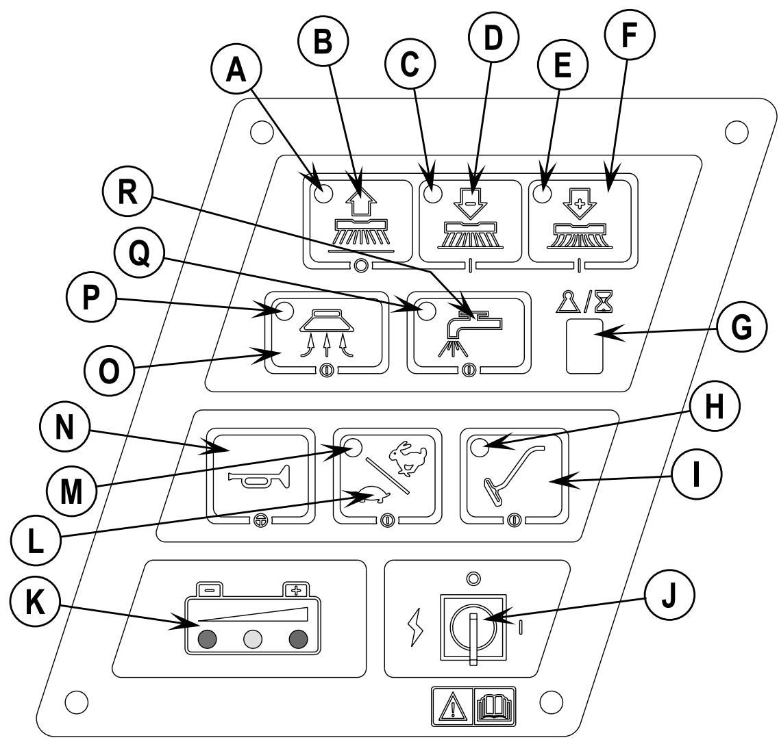
CONTROL PANEL
A Scrub OFF Indicator
B Scrub OFF Switch
C Scrub Pressure Decrease Indicator
D Scrub Pressure Decrease Switch
E Scrub Pressure Increase Indicator
F Scrub Pressure Increase Switch
G Scrub Pressure / Hourmeter Display
H Wand Switch Indicator
I Wand Switch
J Key Switch
K Battery Condition Indicator
L Speed Select Switch
M Speed Select Indicator
N Horn Switch
O Vacuum Switch
P Vacuum System Indicator
Q Solution System Indicator
R Solution Switch
DESCRIPTION OF THE BATTERY CONDITION INDICATORS
The battery condition indicator (K) consists of three lights, a green, a yellow, and a red. The voltage indication will change based on the cutoff level (standard or alternate) selected in the control unit. The battery voltage ranges for the various indications are listed below:
| Standard | Alternate | |
| Green | 34.00+ | 34.50+ |
| Green & Yellow | 33.00-33.99 | 34.00-34.49 |
| Yellow | 32.00-32.99 | 33.50-33.99 |
| Yellow & Red | 31.50-31.99 | 33.00-33.49 |
| Red | 31.00-31.49 | 32.50-32.99 |
| Flashing Red/Cutoff | <31.00 <32.50 |
NOTE: Refer to service manual for selection of alternate cut-off level. Once the low voltage cutout level has been reached (flashing red indicator) the batteries must be FULLY recharged to reset the battery condition indicator. The scrub system will not function until the indicator has been reset.
INSTALL THE BATTERIES

WARNING!
Use extreme caution when working with batteries. Sulfuric acid in batteries can cause severe injury if allowed to contact the skin or eyes. Explosive hydrogen gas is vented from inside the batteries through openings in the battery caps. This gas can be ignited by any electrical arc, spark or flame.
When Servicing Batteries...
* Remove all jewelry.
* Do not smoke.
* Wear safety glasses, a rubber apron and rubber gloves.
* Work in a well-ventilated area.
* Do not allow tools to touch more than one battery terminal at a time.

CAUTION!
Electrical components in this machine can be severely damaged if the batteries are not installed and connected properly.
Batteries should be installed by Nilfisk-Advance or by a qualified electrician.
1 Turn the Key Switch (J) off (O) and remove the key. Then swing open the Battery Compartment Cover (16).
2 Using (2) people and an appropriate lifting strap, carefully lift the batteries into the compartment tray exactly as shown. Refer to decal 56015168 battery cable layout.
3 See Figure 1. Install battery cables as shown and tighten the nuts on the battery terminals.
4 Install the battery boots and secure tightly to the battery cables with the supplied tie straps.
5 Connect the battery pack connector to the machine connector (22) and close the battery compartment cover.
FIGURE 1
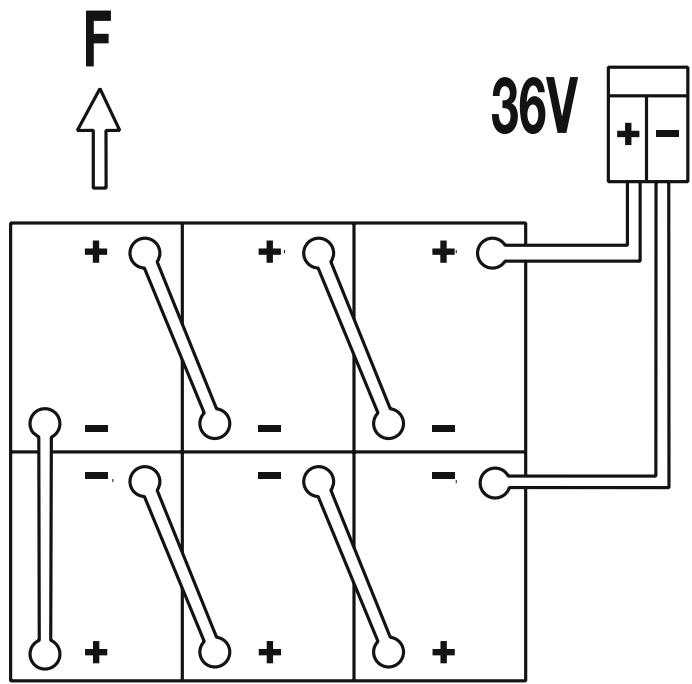
305A/H - 20HR - RATE
INSTALL THE BRUSHES (DISC SYSTEM)

CAUTION!
Turn the key switch off (O) and remove the key, before changing the brushes, and before opening any access panels.
1 Make sure the Key Switch (J) is off (O). To access the brushes, remove both side skirt assemblies. Note: The skirts are held in place by a two large Knobs, loosen these knobs and slide the skirt assemblies off of the Scrub Deck.
2 To mount the brushes (or pad holders) align the lugs on the brush with the holes on the mounting plate and turn to lock in place (turn outside edge of brush towards front of machine).
INSTALL THE BRUSHES (CYLINDRICAL SYSTEM)

CAUTION!
Turn the key switch off (O) and remove the key, before changing the brushes, and before opening any access panels.
1 Make sure the Key Switch (J) is off (O). To access the brushes, swing both side skirt assemblies open. Note: The skirts are held in place by a large cotter pin on each side, remove the pins and swing the skirt assemblies out of the way. Loosen the black knobs (one on each side) on top of the idler assemblies and remove the idler assemblies. Slide the brush into the housing, lift slightly, push and turn until it seats. Re-install the idler assemblies, close the skirt assemblies and secure with cotter pins.
INSTALL THE SQUEEGEE
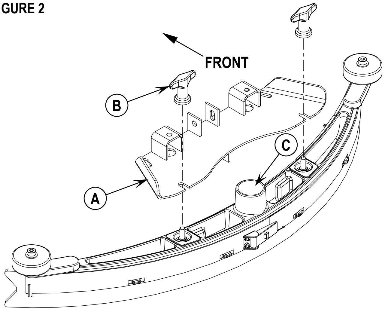
1 Make sure the Squeegee (19) is up (O) and the Key Switch (J) is off (O). Hold the squeegee tool so that the curved ends point forward, then slide the squeegee tool onto the Mount (A) (See Figure 2).
2 Hand tighten the Thumb Nuts (B) and then connect the vacuum hose to the Squeegee Tube (C) (vacuum hose should loop to the right).
FILL THE SOLUTION TANK
Read the cleaning chemical label and figure the proper amount of chemical to mix for a tank that holds 30 US gallons (113 liters).
Open the Solution Tank Cover (2), then fill the tank 1/3 full of water, add the cleaning chemical, then fill the tank to 7.62cm (3 inches) from the top of the tank opening (fill to bottom of the wall in tank opening). NOTE: AXP/EDS machines can either be used conventionally with detergent mixed in the tank or the detergent dispensing system can be used. When using the AXP/EDS detergent dispensing do not mix detergent in the tank, plain water should be used.

CAUTION!
Use only low-foaming, non-flammable liquid detergents intended for automatic scrubber machine applications. Water temperature should not exceed 130 degrees Fahrenheit (54.4 degrees Celsius).
FIGURE 2
DETERGENT SYSTEM PREPARATION AND USE (AXP/EDS MODELS ONLY)
COMMON INSTRUCTIONS:
The system should be purged of previous detergent when switching to a different detergent. SERVICE NOTE: Move machine over floor drain before purging because a small amount of detergent will be dispensed in the process.
To Purge When Changing Chemicals:
1 Disconnect and remove the detergent cartridge.
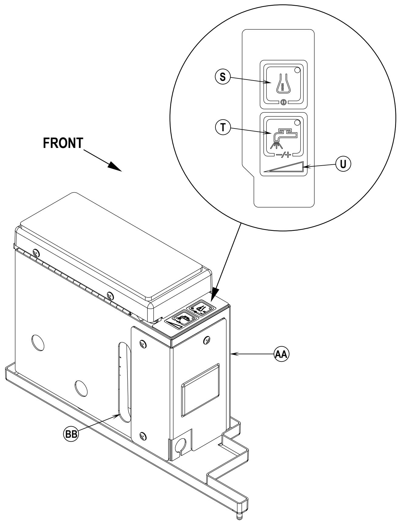
2 Turn the Key Switch (J) ON and press the Detergent ON/OFF Switch (S) and the Flow Rate Switch (T) down for at least 3 seconds. NOTE: Once activated the Flow Rate Indicator (U) will begin to flash and will automatically shut off after 10 seconds. Normally one purge cycle is adequate to purge the system.
To Purge Weekly:
1 Disconnect and remove the detergent cartridge. Install and connect a Cartridge filled with clean water
2 Turn the Key Switch (J) ON and press the Detergent ON/OFF Switch (S) and the Flow Rate Switch (T) down for at least 3 seconds. NOTE: Once activated the Flow Rate Indicator (U) will begin to flash and will automatically shut off after 10 seconds. Normally one purge cycle is adequate to purge the system.
The Detergent Box (AA) has a Detergent Level Viewing Slot (BB) for keeping track of how much detergent is remaining in the cartridge. When the detergent level is nearing the bottom of this slot it is time to refill or replace the cartridge.
General Use:
The detergent (AXP/EDS) system is turned on when the Key Switch (J) is turned on but no detergent is dispensed until the scrub system is activated and the Drive Pedal (8) pushed forward. The solution flow rate automatically defaults to the last setting used. The solution flow rate can be varied by subsequently pressing the Flow Rate Switch (T). There are four solution flow rates indicated by the Flow Rate Indicator (U). The detergent flow rate increases or decreases with the solution flow rate but the detergent ratio remains the same. During scrubbing, the detergent system can be turned off at any time by pressing the Detergent ON/OFF Switch (S) to allow scrubbing with water only. The solution flow rate is controlled by the Flow Rate Switch (T) whether the detergent system is ON or OFF.
SERVICE NOTE: Follow the “To Purge Weekly” instructions above if the machine is going to be stored for an extended period of time or if you plan to discontinue use of the detergent (AXP/EDS) system.
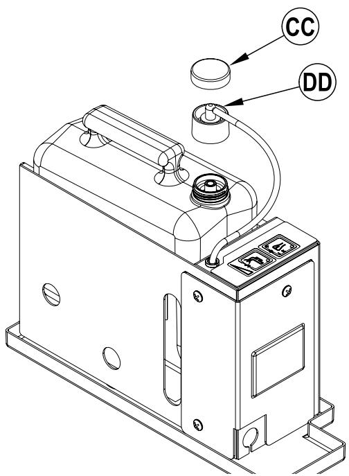
DISPOSABLE CARTRIDGE SPECIFIC INSTRUCTIONS:
Remove the Cap (CC) and place the cartridge in the detergent box. Install the Dry Break Cap (DD) as shown.
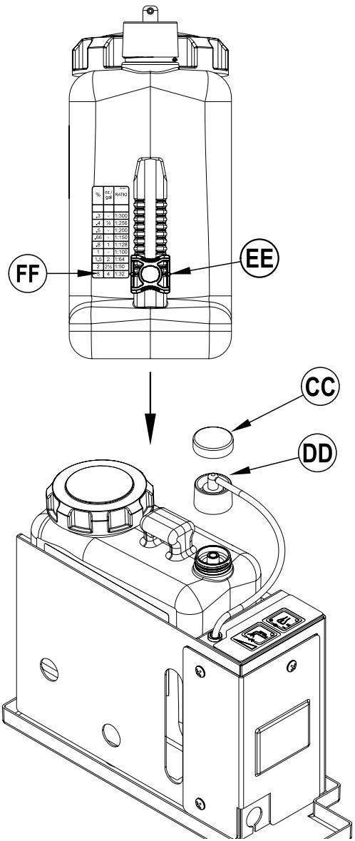
NON-DISPOSABLE CARTRIDGE SPECIFIC INSTRUCTIONS:
Fill the detergent cartridge with a maximum of 1.25 gallons (4.73 Liters) of detergent. SERVICE NOTE: Remove the detergent cartridge from the detergent box prior to filling to avoid spilling detergent on the machine.
It is recommended that a separate cartridge be used for each detergent you plan to use. The detergent cartridges have a white decal on them so you can write the detergent name on each cartridge to avoid mixing them up. The detergent cartridge has a Magnetic Slider (EE) on one end that needs to be set to the proper dilution ratio according to the dilution instructions on the manufacturer's bottle. Slide the Magnet Slider (EE) to the appropriate location on Detergent Dilution Ratio Decal (FF). When installing a new cartridge, remove the Cap (CC) and place the cartridge in the detergent box. Install the Dry Break Cap (DD) as shown.
DETERGENT SYSTEM PREPARATION AND USE (AXP/EDS MODELS ONLY)
Be sure you understand the operator controls and their functions.
While on ramps or inclines, avoid sudden stops when loaded. Avoid abrupt sharp turns. Use low speed down hills. Clean only while ascending (driving up) the ramp.
To Scrub...
Follow the instructions in preparing the machine for use section of this manual.
1 While seated on the machine, adjust the seat and steering wheel to a comfortable operating position using the adjustment controls (25) and (5).
2 Turn the Master Key Switch (J) ON (I). This will display the control panel indicator lights, reference the Battery Condition Indicator (K) and Hour Meter (G).
3 Release the Parking Brake (6). To transport the machine to the work area, apply even pressure with your foot on the front of the Drive Pedal (8) to go forward or the rear of the pedal for reverse. Vary the pressure on the foot pedal to obtain the desired speed.
4 Adjust the Solution Flow Control Valve Lever (7) to about 1/4 to 1/3 open position (Non AXP/EDS models).
Press the Flow Rate Switch (T) to select a solution flow rate (AXP/EDS models).
The flow rate can be changed to allow variable solution flow for different types of floors to be scrubbed. Example: A rough or absorbent floor surface such as unfinished concrete, will require more solution than a smooth finished floor.
NOTE (Non AXP/EDS Models): For a consistent reduced flow of solution; open the Solution Flow Control Valve Lever (7) all the way and then turn ON the Smart Solutions™ / ECO Solution™ Valve (26). When the lever is in the “OFF” position; the machine operates conventionally; solution flow is determined by the Solution Flow Control Lever (7). When the lever is in the “ON” position; solution flow is controlled automatically. The Solution Flow Control Lever (7) should not be shut off, but is otherwise inactive. Make sure that the lever for Valve (26) is all the way ON or all the way OFF, never in between. If more solution is needed, turn OFF the Smart Solutions™ / ECO Solution™ Valve (26) and adjust the solution flow with the Solution Flow Control Valve Lever (7).
NOTE: The solution, vacuum and detergent (AXP/EDS models) systems are automatically activated when the Scrub Pressure Decrease Switch (D) or the Scrub Pressure Increase Switch (F) is pressed. No further action is required. Any individual system can be turned OFF or back ON by simply pressing its switch at any time during scrubbing.
5 Press and hold the Solution Switch (R) for 5 seconds to pre-wet the floor. NOTE: This must be done prior to pressing the Scrub ON Switch (F).
6 When the Scrub Pressure Decrease Switch (D) or the Scrub Pressure Increase Switch (F) is selected, the brushes and squeegee are automatically lowered to the floor. The machine's scrub brush rotation, solution system flow, vacuum and detergent (AXP/EDS models) starts when the Drive Pedal (8) is activated. Note: When operating the machine in reverse, only the brushes will rotate, the solution and detergent (AXP/EDS models) is automatically shut off to conserve usage.
7 Begin scrubbing by driving the machine forward in a straight line at a normal walking speed and overlap each path by 2-3 inches (50-75 mm). Adjust when necessary the machine speed and solution flow according to the condition of the floor.

CAUTION!
To avoid damaging the floor, keep the machine moving while the brushes are turning.
8 When scrubbing, check behind the machine occasionally to see that all of the waste water is being picked up. If there is water trailing the machine, you may be dispensing too much solution, the recovery tank may be full, or the squeegee tool may require adjustment.
9 For extremely dirty floors, a one-pass scrubbing operation may not be satisfactory and a “double-scrub” operation may be required. This operation is the same as a one-pass scrubbing except on the first pass the squeegee is in the up position (press the Vacuum Switch (O) to raise the squeegee). This allows the cleaning solution to remain on the floor to work longer. The final pass is made over the same area, with the squeegee lowered to pick up the accumulated solution.
10 The recovery tank has an automatic float shut-off to prevent solution from entering the vacuum system when the recovery tank is full. When the float shut-off is activated, the control system will shut down the scrub, vacuum, solution and detergent (AXP/EDS models) systems. The Scrub Pressure / Hourmeter Display (G) will display "FULL". To clear the display, press the Scrub OFF Switch (B), Scrub Pressure Decrease Switch (D), Scrub Pressure Increase Switch (F) or the Vacuum Switch (O). When the float closes, the recovery tank must be emptied. The machine will not pick up water with the float closed. NOTE: If the control repeatedly gives a full indication when the tank is not full, the automatic shut-off feature can be disabled, have a qualified service technician refer to the service manual to perform this function.
11 When the operator wants to stop scrubbing or the recovery tank is full, press the Scrub OFF Switch (B) once. This will automatically stop the scrub brushes and solution flow and the scrub deck will raise UP. NOTE: the vacuum/squeegee system will not be turned off when the switch is only pressed once, this is to allow any remaining water to be picked up without turning the vacuum back on. Press the switch a second time and the squeegee will raise and the vacuum will stop after a 10 second delay.
12 Drive the machine to a designated waste water “DISPOSAL SITE” and empty the recovery tank. To empty, pull the Drain Hose (21) from its rear storage area, then remove the plug (hold the end of the hose above the water level in the tank to avoid sudden, uncontrolled flow of waste water). Refill the solution tank and continue scrubbing.
WET VACUUMING
Steps to follow in fitting the machine with optional attachments for wet vacuuming.
1 Disconnect the recovery hose from the squeegee. Connect the coupler and hose from the wand kit to the recovery hose.
2 Attach suitable wet pick-up tools to the hose. (An optional Wand Kit PN56314307 is available from Nilfisk-Advance).
3 Turn the Master Key Switch (J) ON, next press the Wand Switch (I). The vacuum motor and pump will run continuously until the switch is pressed again to turn them OFF. NOTE: If the control repeatedly gives a full indication when the tank is not full, the automatic shut-off feature can be disabled, have a qualified service technician perform this function.
AFTER USE
When finished scrubbing, press the Scrub Off Switch (B) twice, this will automatically raise, retract and stop all the machine systems (brush, squeegee, vacuum, solution and detergent (AXP/EDS models)). Then drive the machine to a service area for daily maintenance and review of other needed service up keep.
2 To empty the solution tank, remove the Solution Drain Hose (4) from its storage clamp. Direct the hose to a designated "DISPOSAL SITE" and remove the plug. Rinse the tank with clean water.
3 To empty the recovery tank, pull the Recovery Tank Drain Hose (21) from its storage area. Direct the hose to a designated "DISPOSAL SITE" and remove the plug (hold the end of the hose above the water level in the tank to avoid sudden, uncontrolled flow of waste water). Rinse the tank with clean water.
4 Remove the brushes or pad holders. Rinse the brushes or pads in warm water and hang up to dry.
5 Remove the squeegee, rinse it with warm water and re-install on mount.
6 Remove the hopper on cylindrical systems and clean thoroughly. Remove from either side of the machine by opening the skirt and tilting the hopper up and away from housing, then pull out.
7 Check the maintenance schedule below and perform any required maintenance before storage
MAINTENANCE SCHEDULE
| MAINTENANCE ITEM | Daily | Weekly | Monthly | Yearly |
| Charge Batteries | X | |||
| Check/Clean Tanks & Hoses | X | |||
| Check/Clean/Rotate the Brushes/Pads | X | |||
| Check/Clean the Squeegee | X | |||
| Check/Clean Vacuum Shut-Off Float | X | |||
| Check/Clean the vacuum motor foam filter(s) | X | |||
| Clean Hopper on Cylindrical System | X | |||
| Check Each Battery Cell(s) Water Level | X | |||
| Inspect Scrub Housing Skirts | X | |||
| Inspect and clean Solution Filter | X | |||
| Check Foot/ Parking Brake For Wear & Adjustment | X | |||
| Clean Solution Trough on Cylindrical System | X | |||
| Purge Detergent System (AXP/EDS only) | X | |||
| Lubrication - Grease Fittings | X | |||
| * Check Carbon Brushes | X |
* Have Nilfisk-Advance check the vacuum motor carbon motor brushes once a year or after 300 operating hours. The brush and drive motor carbon brushes check every 500 hours or once a year.
NOTE: Refer to the Service Manual for more detail on maintenance and service repairs.
8 Store the machine indoors in a clean dry place. Keep from freezing. Leave the tanks open to air them out.
9 Turn the Master Key Switch (J) OFF (O) and remove the key.
LUBRICATING THE MACHINE
Once a month, pump a small amount of grease into each grease fitting on the machine until grease seeps out around the bearings.
Grease fitting locations are:
• Squeegee Caster Wheel Axle
• Steering Wheel Shaft Universal joint
Once a month, apply light machine oil to lubricate the:
- Steering Chain
• General Pivot Points For the Squeegee, Brush Linkage and Side Skirts
• Squeegee mount angle adjustment knob threads
CHARGING THE BATTERIES
Charge the batteries each time the machine is used, or whenever the Battery Condition Meter (K) is showing a yellow, red or flashing red indicator light(s).
To Charge the Batteries...
1 Depress the Battery Disconnect (13).
2 Open the Battery Compartment Cover (16) to provide proper ventilation.
3 Push the connector from the charger into the Battery Connector (22).
4 Follow the instructions on the battery charger.
5 Check the fluid level in all battery cells after charging the batteries. Add distilled water, if necessary, to bring the fluid level up to the bottom of the filler tubes.

WARNING!
Do not fill the batteries before charging.
Only charge batteries in a well-ventilated area.
Do not smoke while servicing the batteries.

CAUTION!
To avoid damage to floor surfaces, always wipe water and acid from the top of the batteries after charging.
CHECKING THE BATTERY ELECTROLYTE LEVEL
Check the electrolyte level of the batteries at least once a week.
After charging the batteries, remove the vent caps and check the electrolyte level in each battery cell. Use distilled water to fill the batteries to the bottom of the filler tube.
Do not over-fill the batteries!

CAUTION!
Acid can spill onto the floor if the batteries are overfilled.
Tighten the vent caps. If there is acid on the batteries, wash the tops of the batteries with a solution of baking soda and water (2 tablespoons of baking soda to 1 quart of water).
If the squeegee leaves narrow streaks or water, the blades may be dirty or damaged. Remove the squeegee, rinse it under warm water and inspect the blades. Reverse or replace the blades if they are cut, torn, wavy or worn.
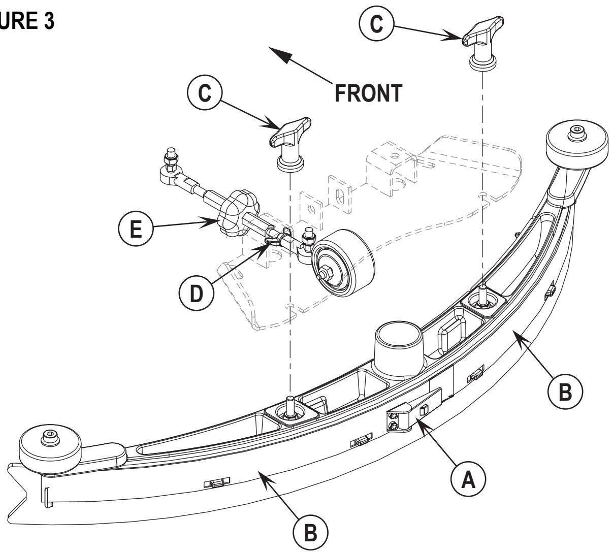
To Reverse or Replace the Rear Squeegee Wiping Blade...
1 See Figure 3. Raise the squeegee tool off the floor, then unsnap the Center Latch (A) on the squeegee tool.
2 Remove the Tension Straps (B).
3 Slip the rear blade off the alignment pins.
4 The squeegee blade has 4 working edges. Turn the blade so a clean, undamaged edge points toward the front of the machine. Replace the blade if all 4 edges are nicked, torn or worn to a large radius.
5 Install the blade, following the steps in reverse order and adjust the squeegee tilt.
To Reverse or Replace the Front Squeegee Blade...
1 Raise the squeegee tool off the floor, then loosen the (2) Thumb Nuts (C) on top of the squeegee and remove the squeegee tool from the mount.
2 Remove both rear Tension Straps first.
3 Remove all the wing nuts that hold the front blade in place, then remove tension strap and blade.
4 The squeegee blade has 4 working edges. Turn the blade so a clean, undamaged edge points toward the front of the machine. Replace the blade if all 4 edges are nicked, torn or worn to a large radius.
5 Install the blade, following the steps in reverse order and adjust the squeegee tilt.
SQUEEGEE ADJUSTMENT
There is just one squeegee tool adjustment possible, angle.
Adjusting the Squeegee Angle
Adjust the squeegee angle whenever a blade is reversed or replaced, or if the squeegee is not wiping the floor dry.
1 Park the machine on a flat, even surface and lower the squeegee. Then drive the machine forward enough to have the squeegee blades fold over to the rear.
2 Loosen the Lock Wing Nut (D) (hand tightened). This secures the squeegee mount angle from easily vibrating out of adjustment.
3 Turn the Adjustment Knob (E) to tilt the tool forward or backwards, until the rear squeegee wiping blade touches the floor evenly across its entire width.
4 Re-tighten by hand the Lock Wing Nut (D).
FIGURE 3
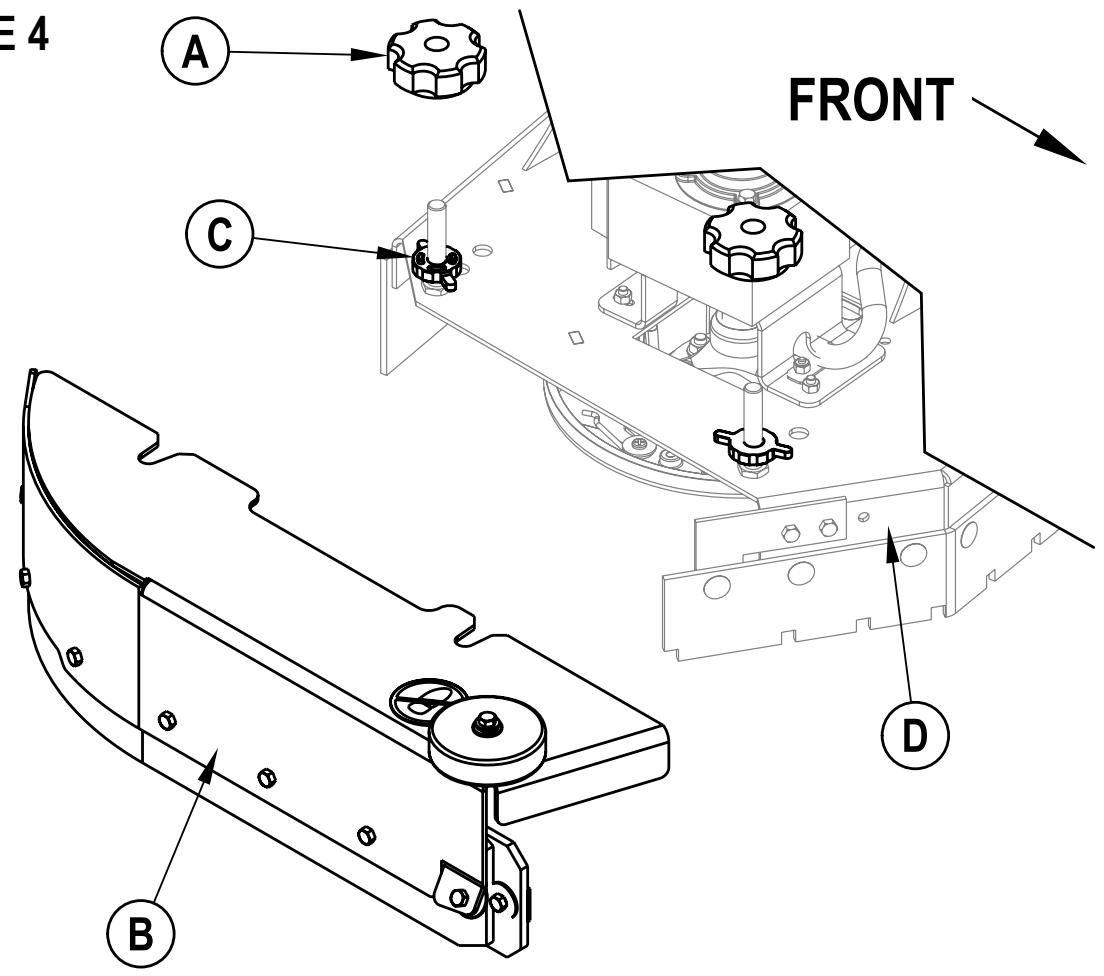
The side skirt's function is to channel the waste water to the squeegee, helping contain the water within the machines cleaning path. During normal use the blades will wear in time. The operator will notice a small amount of water leaking out underneath the side skirts. A height adjustment can easily be made to lower the blades so that all the water can be pick-up by the squeegee.
To reverse or replace the scrub system side skirt(s) ...
1 See Figure 4. Loosen the (2) side skirt Retainer Knobs (A) (2 per side) and pull the Skirt Assemblies (B) off from the scrub deck.
2 Remove all the hardware that holds the blades to the skirt housings.
3 Replace the blades as a set if they are nicked, torn or worn beyond their ability to be adjusted.
4 Reinstall the skirt housing assemblies onto the machine and adjust the blade for proper contact to the floor when the brush deck is placed in the scrub position.
SIDE SKIRT HEIGHT ADJUSTMENT (DISC SYSTEM)
1 The side skirt housing knob retainer screw studs have leveling Adjuster Collars (C), that are to be raised or lowered to compensate for blade wear.
2 To adjust, remove the Skirt Assemblies (B) from the Scrub Deck (D) to access the Adjuster Collars (C). Adjustment Tip: The skirts Retainer Knobs (A) can be loosened with skirts left on and the Adjuster Collars (C) rotated by reaching under the skirt housing.
3 Turn the Adjuster Collars (C) (Up or Down) to where the blades just fold over enough when scrubbing that all the waste water is contained inside the skirting. Note: Make small adjustments to obtain good blade wiping. Do not lower the blades too much to where they fold over excessively and cause unneeded blade wear.
FIGURE 4
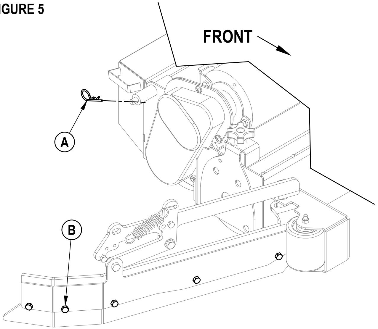
The side skirts function is to channel the waste water to the squeegee, helping contain the water within the machines cleaning path. During normal use the blades will wear in time. The operator will notice a small amount of water leaking out underneath the side skirts. Skirt height adjustment is automatic on this system. The skirt assemblies should move up and down freely for proper operation.
To replace the scrub system side skirt(s) ...
1 See Figure 5. Remove the (2) (A) Cotter Pins and swing the Skirt Assemblies open. Remove the (B) Screws and Nuts, remove the Skirts and replace.
FIGURE 5
GENERAL MACHINE TROUBLESHOOTING
| Problem | Possible Cause | Remedy |
| Poor water pick-up | Worn or torn squeegee blades | Reverse or replace |
| Squeegee out of adjustment | Adjust so blades touch floor evenly across entire width | |
| Recovery tank full | Empty recovery tank | |
| Recovery tank drain hose leak | Secure drain hose cap or replace | |
| Recovery tank cover gasket leak | Replace gasket / Seat cover properly | |
| Debris caught in squeegee | Clean squeegee tool | |
| Vacuum hose clogged | Remove debris | |
| Using too much solution | Adjust solution control valves | |
| Foam filter cover not seated | Seat cover properly | |
| Poor scrubbing performance | Worn brush or pad | Rotate or replace brushes |
| Wrong brush or pad type | Consult Nilfisk-Advance | |
| Wrong cleaning chemical | Consult Nilfisk-Advance | |
| Moving machine too fast | Slow down | |
| Not using enough solution | Adjust solution control valves | |
| Inadequate solution flow or no solution | Solution tank empty | Fill solution tank |
| Solution lines, valves, filter or trough clogged | Flush lines, trough and clean solution filter | |
| Solution control valves not open | Adjust solution control valves | |
| Solution solenoid valve | Clean or replace valve | |
| Machine does not run | Emergency stop switch tripped | Reconnect battery connectors |
| Operator seat safety switch | Check for open circuit and replace | |
| Main system controller | Check error fault codes (see service manual) | |
| Tripped 10 Amp circuit breaker | Check for electrical short circuit & reset | |
| No FWD/REV wheel drive | Drive system speed controller | Check error fault codes (see service manual) |
| Tripped 45 Amp circuit breaker | Check for drive motor overload | |
| Emergency stop switch tripped | Reconnect battery connectors | |
| Vacuum shuts off and display shows “FULL” when recovery tank is not full | Plugged squeegee hose | Clear debris |
| Vacuuming large amounts of water at a high travel speed | Slow down or disable auto shut-off feature (see service manual) | |
| Poor Sweeping Performance (Cylindrical System) | Hopper Full | Empty and clean hopper |
| Brushes worn | Replace brushes | |
| Bristles have taken a set | Rotate brushes | |
| No Detergent Flow (AXP/EDS models only) | Empty detergent cartridge | Fill detergent cartridge |
| Plugged or kinked detergent flow line | Purge system, straighten lines to remove any kinks | |
| Dry seal cap on detergent cartridge not sealed | Reseat dry seal cap | |
| Detergent ratio slider magnet missing | Replace slider | |
| Detergent pump wiring disconnected or backwards | Connect or reconnect wiring |
TECHNICAL SPECIFICATIONS (as installed and tested on the unit)
| Model | BR 600S | BR 650S | BR 700S | BR 800S | |
| Advenger^TM 2400D | Advenger^TM 2600D | Advenger^TM 2810D | Advenger^TM 3210D | ||
| Model No. | 56314010 | 56314011 | 56314012 | 56314013 | |
| 56314000 | 56314001 | 56314002 | 56314003 | ||
| Voltage, Batteries | V | 36V | 36V | 36V | 36V |
| Battery Capacity | Ah | 305 | 305 | 305 | 305 |
| Protection Grade | IPX3 | IPX3 | IPX3 | IPX3 | |
| Sound Pressure Level (IEC 60704-1) | dB(A)/20μPa | 65 | 65 | 65 | 65 |
| Gross Weight | Ibs / kg | 1,380 / 626 | 1,385 / 628 | 1,385 / 628 | 1,390 / 630 |
| Vibrations at the Hand Controls (ISO 5349-1) | m/s2 | 1.03m/s2 | 1.03m/s2 | 1.03m/s2 | 1.03m/s2 |
| Vibrations at the Seat (EN 1032) | m/s2 | 0.24m/s2 | 0.24m/s2 | 0.24m/s2 | 0.24m/s2 |
| Gradeability | |||||
| Transport | 14% (8°) | 14% (8°) | 14% (8°) | 14% (8°) | |
| Cleaning | 10% (6°) | 10% (6°) | 10% (6°) | 10% (6°) | |
| Model | BR 600SC | BR 650SC | BR 700SC | BR 800SC | |
| Advenger^TM 2400C | Advenger^TM 2600C | Advenger^TM 2810C | Advenger^TM 3210C | ||
| Model No. | 56314014 | 56314015 | 56314016 | 56314017 | |
| 56314004 | 56314005 | 56314006 | 56314007 | ||
| Voltage, Batteries | V | 36V | 36V | 36V | 36V |
| Battery Capacity | Ah | 305 | 305 | 305 | 305 |
| Protection Grade | IPX3 | IPX3 | IPX3 | IPX3 | |
| Sound Pressure Level (IEC 60704-1) | dB(A)/20μPa | 65 | 65 | 65 | |
| Gross Weight | Ibs / kg | 1,385 / 628 | 1,390 / 630 | 1,390 / 630 | 1,395 / 633 |
| Vibrations at the Hand Controls (ISO 5349-1) | m/s2 | 1.03m/s2 | 1.03m/s2 | 1.03m/s2 | 1.03m/s2 |
| Vibrations at the Seat (EN 1032) | m/s2 | 0.24m/s2 | 0.24m/s2 | 0.24m/S2 | 0.24m/s2 |
| Gradeability | |||||
| Transport | 14% (8°) | 14% (8°) | 14% (8°) | 14% (8°) | |
| Cleaning | 10% (6°) | 10% (6°) | 10% (6°) | 10% (6°) | |
| Model | BP 600S EDS | BR 700S EDS | BR 800S EDS | ||
| Advenger^TM 2810D-AXP | Advenger^TM 3210D-AXP | ||||
| Model No. | 56316517 | 56314996 | 56314997 | ||
| 56314992 | 56314993 | ||||
| Voltage, Batteries | V | 36V | 36V | 36V | |
| Battery Capacity | Ah | 305 | 305 | 305 | |
| Protection Grade | IPX3 | IPX3 | IPX3 | ||
| Sound Pressure Level (IEC 60704-1) | dB(A)/20μPa | 65 | 65 | 65 | |
| Gross Weight | Ibs / kg | 1,385 / 628 | 1,385 / 628 | 1,390 / 630 | |
| Vibrations at the Hand Controls (ISO 5349-1) | m/s2 | 1.03m/s2 | 1.03m/s2 | 1.03m/s2 | |
| Vibrations at the Seat (EN 1032) | m/s2 | 0.24m/s2 | 0.24m/s2 | 0.24m/s2 | |
| Gradeability | |||||
| Transport | 14% (8°) | 14% (8°) | 14% (8°) | ||
| Cleaning | 10% (6°) | 10% (6°) | 10% (6°) | ||
| Model | BR 600SC EDS | BR 700SC EDS | BR 800SC EDS | ||
| Advenger^TM 2810C-AXP | Advenger^TM 3210C-AXP | ||||
| Model No. | 56316518 | 56314998 | 56314999 | ||
| 56314994 | 56314995 | ||||
| Voltage, Batteries | V | 36V | 36V | 36V | |
| Battery Capacity | Ah | 305 | 305 | 305 | |
| Protection Grade | IPX3 | IPX3 | IPX3 | ||
| Sound Pressure Level (IEC 60704-1) | dB(A)/20μPa | 65 | 65 | 65 | |
| Gross Weight | Ibs / kg | 1,385 / 628 | 1,390 / 630 | 1,395 / 633 | |
| Vibrations at the Hand Controls (ISO 5349-1) | m/s2 | 1.03m/s2 | 1.03m/s2 | 1.03m/s2 | |
| Vibrations at the Seat (EN 1032) | m/s2 | 0.24m/s2 | 0.24m/s2 | 0.24m/s2 | |
| Gradeibility | |||||
| Transport | 14% (8°) | 14% (8°) | 14% (8°) | ||
| Cleaning | 10% (6°) | 10% (6°) | 10% (6°) |
ÍNDICE
página
Larry Doerr, Vice President Operations
Nilfisk-Advance, Inc.
14600 21st Avenue North
Plymouth, MN 55447 USA
Nilfisk-Advance A/S
Sognevej 25
DK-2605 Brøndby, Denmark