
MPC5000 - Music production equipment AKAI - Free user manual and instructions
Find the device manual for free MPC5000 AKAI in PDF.


User questions about MPC5000 AKAI
0 question about this device. Answer the ones you know or ask your own.
Ask a new question about this device
Download the instructions for your Music production equipment in PDF format for free! Find your manual MPC5000 - AKAI and take your electronic device back in hand. On this page are published all the documents necessary for the use of your device. MPC5000 by AKAI.
USER MANUAL MPC5000 AKAI
Chapter 1: Introduction.
Overview. 1
Top Panel. 1
Front Panel 7
Rear Panel 8
Bottom Panel 9
Hooking Up Your MPC5000 10
Output Connectivity Example. 10
Analog Input Connectivity Example. 10
Digital Connectivity Example 11
USB Connectivity. 11
■MIDI Connectivity 12
Footswitch/Headphone Connectivity. 12
Basic Concepts and Terminology 13
■ Sequence. 13
Tracks. 13
■ Song. 13
Sample 13
Drum Pad. 14
Sample Program 14
Synth Programs 14
Note Number, Velocity, and Length 14
RAM. 14
Memory Card 14
Operating Modes 15
MAIN Mode ([MAIN]) 15
Q-LINK Mode ([MODE] + [Pad 1]) 15
DISK Mode ([MODE] + [Pad 3]) 15
REC SAMPLE Mode ([MODE] + [Pad 4]) 15
TRIM Mode ([MODE]+[Pad 5]) 15
PROGRAM Mode ([MODE] + [Pad 6]) 15
MIXER Mode ([MODE] + [Pad 7]. 15
MIDI/SYNC Mode ([MODE] + [Pad 8]). 15
OTHER Mode ([MODE] + [Pad 9]) 15
ARP Mode ([MODE] + [Pad 10]) 15
EFFECTS Mode ([MODE]+[Pad 11]). 15
SEQEDITMode([MODE]+[Pad12]) 16
STEPEDITMode([MODE]+[Pad13]) 16
GRIDEDITMode([MODE]+[Pad14]) 16
■ SONG Mode ([MODE] + [Pad 15]) 16
HD RECORD Mode ([MODE] + [Pad 16]). 16
SYNTH Programs ([SYNTH]) 16
Chapter 2: Basic Operation 17
MAIN Page. 17
Cursor, Cursor Buttons, [DATA] wheel 17
Function Buttons 17
[WINDOW]Button 17
[MODE]Button. 17
Setting Names 18
Enterling letters with [DATA] wheel. 18
- Entering letters with the Numeric Keypad. 18
Chapter 3: The Sequencer 19
Main Page 19
Now 19
Sequence 20
Track' field. 20
Track Status' field 20
Recording the Performance 20
■ 'Record Ready' Mode. 21
■ Step Recording 21
Playing Back a Sequence 21
Playing Several Sequences in Series 21
Punch In/Punch Out. 22
Other Useful Features for Recording Sequences 22
Undo and Redo 22
Erase 23
- Deleting In Real Time 23
- Deleting From the Erase Screen 23
Timing correct 24
Real time timing correction 24
Swing 24
Correcting the timing of recorded events 24
Swing. 25
Shift Timing 25
Strength 25
Window 25
Click/Metronome 25
Note Repeat 26
Note Repeat Hold 26
Locate 26
Detailed Information on the Sequence Feature 27
Setting the Length of a Sequence. 27
Setting the Time Signature of the Sequence 27
Setting Tempo 27
Tat Tempo 28
Changing Tempo of All Sequences At One Time 28
About Tempo Change 28
Setting the Loop for a Sequence 28
Extending the Sequence Length Automatically 29
Changing the Default Settings 29
Changing the Sequence Name 29
Changing the Default Name for a Sequence 29
- Copying a Sequence 30
Copying a Sequence Parameters ('Loop', 'Time Sig', 'Bars') 30
- Deleting a Sequence 30
- Deleting All Sequences 30
■ Handling the duration (the length of a note) at the loop boundary 31
Track Features 31
Setting the Track Type. 31
Selecting a Program 31
Sending MIDI Program Changes 31
Track Velocity 32
Track Mute 32
Setting the MIDI Output Channel 32
Changing a Track Name 32
Changing the Default Name for a Track 32
■ Copying a Track 33
- Deleting a Track 33
- Deleting all Tracks. 33
Continuous Sample Tracks 34
Selecting a Track with Function Keys 34
Soloing a Track. 34
MIDI Sequencer Features 35
Handling the Sustain Pedal 36
Recording Aftertouch 36
Chapter 4: Editing Sequences 37
Selecting a region for the editing 37
Setting the Range 37
Setting the pad/Note number 37
- Copying events (COPY) 37
■ Moving events (MOVE) 38
Transpose 38
Changing the timing of an event (SHIFT TIMING) 39
Changing the Velocity of an event (Velocity). 39
Changing the duration of an event (DURATION) 40
Selecting the editing region by bar 40
- Copying bars (COPY). 40
Inserting a bar (INSERT). 40 - Deleting a bar (DELETE) 41
Changing the order of tracks (TRACK MOVE) 41
Chapter 5: STEP EDIT Mode 43
A Note about Playing Events. 43
About Step Edit 43
Now' field 43
■ Event List 43
View' field. 43
Event Time' field. 43
Event 43
Basic operation 43
Event List 43
[F1] (T.C.) 43
[F2] (TRACK) 44
[F6] (PLAY). 44
Events 44
Pad Event. 44
■ Tempo Change Event 44
■ Effect Select Event 45
Real Time Event. 45
Note Event. 45
Pitch Bend Event. 45
Control Change Event. 45
■ Program Change Event. 45
Channel Pressure Event 46
■ Poly Pressure Event 46
Exclusive Data Event. 46
Copying / Pasting an Event 46
Moving an Event 46
46
Step Recording 47
Detailed setting for step recording 47
'Auto step increment' field 47
Duration of recorded notes' field 47
Inserting an event 47
Chapter 6: GRID EDIT Mode 49
About Grid Edit. 49
DRUM View 49
■MIDI View. 49
Now. 49
Time ruler 49
Vertical marker. 49
Horizontal marker. 49
Event Range' field 49
Event Area. 49
Basic operation 50
Operation in the Event area 50
■ Relationship of Grid Value to Timing Correct. 50
Selecting an event. 50
Editing in GRID EDIT mode 51
[F1] (T.C.) Button. 51
[F2] (TRACK) Button 51
[F3] (EDIT) Button. 51
[F4] (DELETE) Button. 51
[F6] (PLAY) Button 51
Copying and Pasting an Event 51
Moving an event. 52
Deleting an event 52
Entering an event. 52
Step recording. 52
Detailed Setting for Grid Edit Recording 53
'Auto step increment' field 53
Duration of recorded notes' field. 53
Real time recording. 53
Chapter 7: SONG Mode. 55
Structure of a song 55
55
Now field 55
'Song' field. 55
Step list. 55
Step' field 56
Sequence' field 56
Reps' field 56
'Tempo' field. 56
Bars' field. 56
Creating a song 56
- Deleting a step 56
Inserting a step. 56
Playing a song 57
[F5] (SUDDEN) 57
[F6] (NEXT). 57
Other features in SONG Mode 57
Changing the song name. 57
- Copying a song 57
- Deleting a song. 57
- Deleting all songs 58
Setting all sequences to the same tempo 58
■ Ignoring tempo change events in a sequence 58
Converting a song to a sequence 58
Chapter 8: HD RECORD Mode 61
Adding Hard Disk Tracks to a Song 61
About the RECORD Page. 61
Recording Hard Disk Tracks 62
Recording additional tracks 62
Viewing Recorded Tracks 63
Selecting the View Range 63
Viewing Individual Disk Tracks 63
Choosing the Track to View 64
Editing Hard Disk Tracks 64
Selecting multiple tracks 64
Fine Editing of a Single Track 64
Individual Edit Functions 64
Gain 65
Fade 65
Cut / Copy / Pasting Tracks 65
■Normalize 66
Silence 66
Importing and Exporting Tracks 66
Importing 66
Exporting 67
Mixing Hard Disk Tracks 67
Setting Track Output 67
Setting the level and pan of a Track. 68
■Assigning effects to a Track 68
Muting a Track 69
Using Q-LINK Controls with MIXER Mode. 69
Mixer Automation 69
Mixdown 69
■ Mixdown to File 70
Chapter 9: Functions of a Pad 71
Playing with pads. 71
Switching pad banks. 71
Full level function ([FULL LEVEL] button) 71
16 levels function ([16 LEVEL] button). 71
Muting Sequence Tracks with Pads (Track Mute) 72
Operation 72
Solo Function 72
Selecting Instant Track Mute 72
Setting the Track Mute in Solo Mode 73
■ Recording Track Mutes 73
■ Ignoring Track Mute Events 73
Track Mute Groups. 73
Muting Individual Samples from a Program with Pads (Pad Mute) 74
Operation 74
Pad Mute Groups 74
Selecting a Sequence to Play with Pads 75
Operation 75
SUDDEN Button. 75
HOLDButton 75
Chapter 10: MIXER Mode. 77
Program Mixer 77
Setting the Output. 77
Setting the Level and Pan of a Pad 78
■Assigning Effects to a Pad 78
Muting Pads. 79
Viewing Program Info 79
Track Mixer 80
Setting the Level and Pan Position of a Track 80
Muting a Track 80
Using Q-LINK Controls with MIXER Mode. 81
Viewing Track Details 81
Mixer Automation 81
■ Shortcut between MIXER and EFFECTS mode. 82
Input Thru 82
Applying effects to an incoming signal 82
Chapter 11: Sampling 83
Preparing the recording 83
Starting the recording 84
Sampling - detailed information 85
Recording the digital signal 85
Preparing the recording. 85
Recording the MAIN OUT 85
Preparation For Recording. 85
Recording the internal CD's sound 85
Preparation For Recording. 85
Other Features 86
Monitoring feature. 86
Peak hold/Reset peak feature 86
RECORD INFORMATION Window. 87
Direct Recording feature 87
Preparing the recording. 87
Starting the recording 88
Chapter 12: Sample Editing. 89
Setting the Start / End Points 89
About the waveform display. 89
LEFT / RIGHT / BOTH Waveform View 89
Adjusting the start point. 89
Adjusting the end point 89
Snapping to the Next Zero Crossing (SNAP 0) 90
Zooming in/out. 90
Adjusting the TRIM and LOOP Points at the Same Time (LOCK) 90
Deleting Unused Parts from a Sample (DISCARD) 91
Deleting a Section of a Sample (DELETE) 91
Silencing Part of a Sample (SILENCE) 91
Saving part of a sample as a new sample (EXTRACT) 91
Converting a Stereo Sample to Mono (STEREO TO MONO) 92
Sample window features. 92
Changing the sample name 92
Changing the pitch of a sample 92
■ Copying a sample 92
□ 删除a sample 93
- Deleting all samples. 93
Other editing functions 94
NORMALIZE 94
■ REVERSE 94
TIME STRETCH. 94
PITCH SHIFT (Changing the pitch of the sample) 96
Dividing a Phrase Sample into Several Regions 97
Chop Shop 97
SLICED SAMPLE/PATCHED PHRASE 97
Dividing a Sample Automatically (AUTO) 98
Dividing a Sample into Regions of Equal Length (EQUALLY). 98
Adjusting the Start/End Point of the Region 99
Converting Divided Samples to SLICED SAMPLES 99
Converting PATCHED PHRASE 100
Changing the Tune and Tempo of a Patched Phrase Sample 100
Editing Regions 101
EXTRACT. 101
DIVIDE REGION 101
COMBINE REGION 101
RESTORE 101
Setting the loop 102
Adjusting the loop point 102
Adjusting the end point. 102
Zooming In/Out of the Waveform 102
LINEAR and LOGARITHMIC Displays 102
Linking the Loop Point to the Start Point 103
Auto Phrase Loop 103
Chapter 13: Sample and Synth Programs 105
Sample Programs 105
Creating a Sample Program 105
■Assigning Samples to Pads. 105
Note On vs. One Shot 106
Volume and Tuning For a Sample 106
Velocity 106
Velocity / Cycle / Random Sample Switching (Zone Play) 107
■ Velocity Sample Switching 107
Cycle Switching. 107
Random Sample Switching 107
Changing Pitch with Velocity 108
Playing several samples with one pad. 108
■Assigning One Sample across All Pads (Auto-Chromatic) 108
Simultaneous Playing of Multiple Pads 109
Setting Envelopes 109
Using Filters with Sample Programs 110
Setting the Filter 110
Controlling the Filter with Velocity 111
Mute groups. 112
Limiting the Number of Voices in a Program 112
Setting Voice Overlap 112
Mute Target feature 113
Low Frequency Oscillators (LFO) 113
Purge Unused Samples 114
Synth Programs 115
About Subtractive Synthesis 115
Playing an MPC5000's Synth Program. 115
The Synth Button. 116
Creating a Synth Program. 116
■ Editing with Q-LINK Controls 117
Basic Editing of a Synth Program 117
VCOs. 118
VCF. 120
VCA 122
LFOs. 123
■ MASTER 124
Other Program Functions 125
Changing the program name. 125
■ Copying a program 125
□ Deleting a program 125
□ 删除all programs 126
Setting a Program Change Number 126
■Assigning MIDI Notes to Pads in a Sample Program 126
Changing the Default Note Number Assignment 127
Chapter 14: Arpeggiator 129
Editing the Arpeggiator 129
Latching the Arpeggiator 130
Using the Arpeggiator with Pre-Recorded Tracks 131
Chapter 15: Effects 133
Applying Effects to a Pad 133
Buss Effects vs. Insert Effects 134
Setting an Effect as an Insert 134
Adding additional Effects to the Effects Buss. 135
Effect Buss Chaining 135
About CPU Usage 135
Editing Effects 135
■ Effect List. 135
Routing Effect Buss Output to Individual Outs 146
Using Master Effects 146
■ Editing the Master Effects 147
Editing the Effect Set 147
Changing the name of the Effect Set. 147
■ Copying the effect set. 148
Resetting the effect set. 148
Chapter 16: Saving and Loading (DISK Mode) 149
About memory cards 149
Saving 149
Selecting the destination 149
Creating a New Folder 149
Saving a Sample 150
Saving a Synth or Sample Program 150
Saving all Programs and Samples 151
Saving a Sequence 151
Saving All the Sequences and the Songs at the Same Time 152
Saving All Data In Memory 152
About Input Thru (.IPT) File 153
■ Renaming a File. 153
- Deleting a File 153
■ Copying Files 153
■ Moving Files. 154
Loading 155
Selecting a File 155
Loading a Sample 155
Loading Audio from the Internal CD Drive (optional) 156
Loading a Program 156
- Deleting All Data in Memory Before Loading. 156
Loading a Sequence 157
Loading the ALL File 157
Loading Individual Sequences from the ALL File 157
Loading Only the Effect Set from the ALL File 157
Loading a Folder. 157
Loading a Folder after Deleting All Data in Memory 158
Loading a Project 158
Loading an Input Thru File 158
Burning CDs 159
Audio CDs. 159
Data CDs. 159
Erasing CD-R/Ws. 160
Close Session 160
Autoload 160
Creating an Autolog.. 160
■ Restoring the Factory Autolog.. 161
Turning Autolog Off 161
161
Chapter 17: Q-LINK Controllers 163
Configuring the Q-LINK Sliders & Knobs 163
Resetting the Q-LINK slider / knob value 165
Recording the slider/knob value in a sequence 165
[After]Button. 165
Sending MIDI Continuous Controllers with a Q-LINK 165
Chapter 18: Using the MPC5000 with External Devices. 167
MIDI Clock 167
■ MIDI Sync with the MPC5000 as the master. 167
■ MIDI Sync with the MPC5000 as the slave 167
MIDI Time Code (MTC) 168
Time code Display. 168
MPC5000 as the Slave. 168
MPC5000 as the Master. 168
■ MIDI Machine Control (MMC). 169
Sending MMC to a device 169
Receiving MMC from a device. 169
Connecting the MPC5000 to a MIDI Keyboard with Built-in Sounds 170
Setting the MIDI Input Channel 171
Connecting the MPC5000 as a Multitimbral Sound Module. 171
SettingMIDIChannel. 171
Chapter 19: Connecting the MPC5000 to Your Computer 173
- Connecting the MPC5000 to a Windows - based PC. 173
- Connecting the MPC5000 to the Macintosh 173
Chapter 20: Other Settings 175
Adjusting the Master Level. 175
Tap Average 175
■ Flash Tempo LED 175
Mute/Stop of One-Shot Samples. 175
Setting the ADAT Digital Output. 176
Using the Footswitches 176
■ Adjustment of Pad Sensitivity and Velocity Curve. 177
SYSTEM 177
Initialize To Factory Default. 178
How to Upgrade the MPC5000. 178
Chapter 21: Specifications 179
General 179
Sound Generator 179
Effects 179
■ Sequencer 179
Inputs/Outputs 180
Standard accessories 180
■ Options 180
Data Compatibility 180
MIDI Implementation Chart 181
Index 183
Chapter 1: Introduction
Thank you for purchasing the MPC5000. The MPC5000 is a powerful musical production tool and this manual describes how to use the MPC to its fullest potential. We're sure you'd like to jump in and start using your MPC5000 quickly. To help you do this, check out the MPC5000's Quickstart guide. The Quickstart guide is a separate manual that should have everything you need to start playing quickly.
Once you're ready for more in-depth information, this reference manual is for you. This manual will describe the workings of every single feature and parameter on the MPC5000 and you should be able to find answers to all of your MPC5000 questions here.
Be sure to register your MPC5000 at our website (www.akaipro.com) so we can give you the best possible service. And since the MPC5000's operating system is upgradeable, check the site once in a while for late breaking news. Future versions of the operating system will include things like new features requested by our users as well as improvements to existing features. Also, you might want to check for new beats and samples every once in a while.
We hope your investment will bring you many years of creative enjoyment and help you achieve your musical goals.
Sincerely,
The MPC5000 Team
Overview
In this chapter, we'll go over the basics of the MPC5000 including the name and function of each button, slider, knob, and jack. Next, we'll also cover how to hook up your MPC5000 to the rest of your studio. Finally, we'll review the basic MPC-related concepts and terminology that is found throughout this manual.
Note that in this manual, the names of buttons, knobs, sliders, and input/output jacks are found in brackets and in all caps as follows: [NAME]. Names of different operating modes are displayed in all capitals, such as PROGRAM mode. Fields and parameters on the screen will be indicated by single quotes, such as 'copy sequence'.
Top Panel
Most of the MPC5000's controls are located on the top of the unit. These controls are as follows:
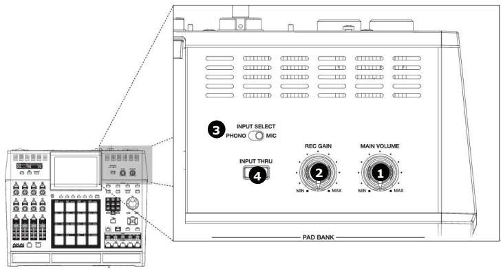
1. [MAIN VOLUME] Knob:
This knob controls the loudness level of the [PHONES] and [STEREO OUT] jacks on the rear of the MPC5000. Use this knob to control the volume of your headphones or speakers.
2. [REC GAIN] Knob:
This knob controls the gain level of the [INPUT] and [PHONO] jacks on the rear of the MPC. Use this knob to set proper input levels before you begin recording your own samples.
3. [INPUT SELECT] Switch:
This switch sets the source for your MPC5000's [INPUT THRU] and record functions. Set this switch to the 'PHONO' position, for sampling from the RCA jacks, (CD player, DJ mixer, Minidisk, etc.) and to the 'MIC' position for recording from the [RECORD IN] MIC/1/4" combo jacks.
4. [INPUT THRU] Button:
Using this button, you can mix the input signal from the [RECORD IN] jacks to the [STEREO OUT] jacks. This way, an additional source can be monitored through the MPC5000's outputs without the need for a mixing board. The level of the input signal is controlled by the [REC GAIN] knob. For more information, see the 'Input Thru' section on page 82.
5. [PAD BANK] Buttons:
These buttons let you switch between pad banks A, B, C, and D, allowing you to have 64 total pads. The currently active bank will be illuminated.
![AKAI MPC5000 - [PAD BANK] Buttons: - 1](/content/2025/01/152537/images/7afccedc2da3f0614a34b98059f04649a73cc1caa6696c8d0932aa3ba3558c52.jpg)
6. [FULL LEVEL] Button:
When this button is engaged, the MPC always plays back at their maximum volume. Pads will be recorded at Maximum MIDI velocity (127). When the button is disengaged, the pads can be played using their entire dynamic range, with the pads getting quieter as you hit softer. Pads will be recorded using the entire MIDI range of velocity (0 -127).
7. [16 LEVEL] Button:
This button allows you to use all 16 drum pads to play one sample with increasing velocity, increased filter effect, or play a single sample at 16 different pitches.
In other words, if 16 levels is set to Velocity, all of the pads play one sample but the velocity of that sample increases as you move from [PAD 1] to [PAD 16]. See page 71 for more about this feature.
8. [TRACK MUTE] Button:
This button calls up the TRACK MUTE page where you can mute or solo your sequence's individual tracks using the pads, or mute individual pads in the current program. For more on Track mutes, see page 72. For more information on Pad mutes, see page 74.
9. [NEXT SEQ] Button:
This button calls up the NEXT SEQ page, where you can switch sequences by pressing a pad. For more information, see the 'Selecting a Sequence to Play with Pads' section on page 75.
![AKAI MPC5000 - [NEXT SEQ] Button: - 1](/content/2025/01/152537/images/d7574df5a14ee8a458c4d8816cc15a4fe255d4568b0af9f15d59a1ebadb63f63.jpg)
10. NUMERIC KEYPAD
These buttons are used to enter numeric data directly. Enter numbers with these buttons into selected numeric fields and press the [ENTER] button. If you are entering numbers with a decimal value, enter the number ignoring the decimal point. (Example: for 120.5, enter 1205.). If you make a mistake, it is possible to cancel by pressing the [SHIFT] button. If you use the [CURSOR] buttons, [DATA] wheel, or [MAIN] button while you are entering data with the numeric buttons, the input will be canceled and the data returns to its original value.
Also, you will notice that much like a telephone, each number also has three or four letters associated with it. These are used for naming programs, tracks, samples etc. For more information on naming, see page 18.
11. [DATA] Wheel / [+] and [-] Buttons:
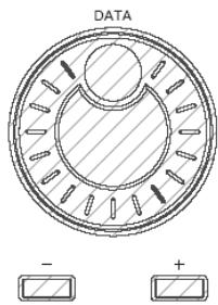
This wheel lets you change the value of the currently selected field. Turning the wheel clockwise increases values (or moves you forward in a list) whereas turning the wheel counterclockwise decreases values or moves you backwards in a list.
Also, the [+] and [-] buttons can be used to change the selected value by single increments. These are best used for fine adjustments.
12. [CURSOR] Buttons:
These four buttons let you move your cursor around the LCD screen to select the various parameters available on screen.
13. [TAP TEMPO] Button:
You can set a sequence's tempo by tapping this button at the desired rate. For more about setting tempos, see 'The Sequencer' on page 19.
![AKAI MPC5000 - [TAP TEMPO] Button: - 1](/content/2025/01/152537/images/39ba72311c4b6dd37a2714a56967f1675592b5a25e2c2d0de04d10b7a2ec1507.jpg)
14. [MAIN] Button:
This is the Main page of the MPC5000 and is displayed when the unit is powered on. Pressing the [MAIN] button at any time will return you to this page. See 'Operating Modes' on page 15 for more about this button.
15. [MODE] Button:
The MPC5000 has several different operating modes and each mode is assigned to its own pad. To shift between these modes, press the [MODE] button and then hit the pad corresponding to the mode you wish to enter. See page 15 for more on this.
16. [SHIFT] Button:
Many of the MPC5000's buttons and pads serve more than one function. Holding the [SHIFT] button while pressing these buttons and pads allows you to access the secondary functions.
17. [UNDO] Button:
If you are unsatisfied with your last performance, you can quickly delete the last take by pressing the [UNDO]. You are also able to undo certain sample editing functions, like Reverse, Discard and Normalize.
![AKAI MPC5000 - [UNDO] Button: - 1](/content/2025/01/152537/images/f452c877b6a2ac0d632e71ff925078ca4ba33f252469be1ddc751cd5107293ff.jpg)
18. [STEP] Buttons ('<' And '>'
These buttons will step you through a sequence according to the value of the timing correct setting. See 'STEP EDIT Mode' on page 43 for more about this.
19. [GO TO] Button:
This button displays the locate window.
Entering a locate point and then pressing [F5] (GO TO) will move you to the selected position in the sequence.
You can also memorize a locate point. Select a point in your sequence and press the [GO TO] button. Select number you want to memorize and press [F2] (CAPTURE) to memorize this point.
![AKAI MPC5000 - [GO TO] Button: - 1](/content/2025/01/152537/images/458ffc118f647ec129a6689b9499877df7754eef027d0b35aa1bb3c35a2bb4e8.jpg)
20. [BAR] Buttons ('<<' And '>>')
These buttons let you move through your sequence by bars. See 'STEP EDIT Mode' on page 43 for more about this.
![AKAI MPC5000 - [BAR] Buttons ('<<' And '>>') - 1](/content/2025/01/152537/images/f4e6f8e1e4f11d8322e86e9b243cd16af53d503a0d3d294ad6ef16152c6ec99e.jpg)
21. [REC] Button:
This button enables recording of your performances. Pressing [REC] + [PLAY START] or [REC] + [PLAY] will begin recording to a sequence. Any existing events in your sequence will be overwritten by your new performance.
You can punch in by pressing [PLAY] + [REC] during playback and punch out by pressing the [REC] button a second time. See page 22 for more about punching in and out on your MPC.
New to the MPC5000 is 'Record Ready' mode. When in 'Record Ready' mode, the MPC will start recording when a MIDI or MMC Start command is received. To enter record ready mode, simply press and release [REC]. The LED will start to blink, indicating that the MPC is in 'Record Ready' mode. The MPC will start recording upon pressing [PLAY] or receiving a MIDI start command. See page 21 for more about 'Record Ready' mode.
Another new function added to the MPC5000 is the ability to perform step recording from the MAIN page by holding down either the [REC] or [OVERDUB] button. For more information, see page 21.
22. [OVERDUB] Button:
This button is quite similar in function to the [REC] button. The only difference is that [OVERDUB] lets you add events to an existing sequence (overhub) instead of overwriting existing events in the sequence.
Press [OVERDUB] + [PLAY START] or [OVERDUB] + [PLAY] to begin overdubbing a sequence. To perform a punch-in, press [PLAY] + [OVERDUB] while the sequence is playing. Press [OVERDUB] to punch out while recording.
23. [STOP] Button:
This button stops playback and recording. Quickly pressing this button three times sends an 'all notes off' MIDI command stops all sounds from playing back.
Note: If your MPC5000 has a 'stuck note' or if a sample is ringing due to improper programming, you can always stop all sounds by quickly tapping the [STOP] button three times.
24. [PLAY] Button:
This button starts playback of a sequence from its current position.
25. [PLAY START] Button:
When looping is disabled, this button will play a sequence from the beginning. Press [PLAY START] to start from the beginning of the sequence regardless of whether looping is enabled or disabled.
![AKAI MPC5000 - [PLAY START] Button: - 1](/content/2025/01/152537/images/d2cbb959f7b368455a07b739a578b9cce7bfcf2498c8a672aa2348300f6a974d.jpg)
26. Display:
This backlit LCD (Liquid Crystal Display) shows you the status of your MPC.
27. [DISPLAY CONTRAST] Knob:
This knob will change the contrast of the LCD display. This will allow the screen to be easily viewed at many different angles.
28. [F1] through [F6] Buttons:
These buttons are used to call up pages at the bottom of the display, or to execute the feature assigned to the button. The available feature depends on the currently displayed screen.
29.[WINDOW]Button
Pressing this button will display a pop up window where you can see more details about the parameter selected on the screen, and allows you to access more in-depth editing of the selected function. When there is more information or parameters available for a particular selection, the [WINDOW] button will light.
This button also acts as a drive activity light when connected via USB. When your computer is accessing the drive, the [WINDOW] button's LED will flash repeatedly.
![AKAI MPC5000 - 29.[WINDOW]Button - 1](/content/2025/01/152537/images/06779d4cb2eeb288631017aaa9e15fa8f500544f4338e0ae9ec2668848eeb944.jpg)
30. [PAD1] Through [PAD16]:
These drum pads let you trigger the samples in your MPC, or play Synth Programs. These pads also let you enter various modes, choose sequences, and mute tracks.
![AKAI MPC5000 - [PAD1] Through [PAD16]: - 1](/content/2025/01/152537/images/8db99a012972aeea2e2e26c16e6f029b003947e170e5afc49326339bd197c6ed.jpg)
31. [SYNTH]
New to the MPC5000 are virtual analog, or 'Synth' programs. Synth programs make sound by a method called 'subtractive synthesis'. From smooth, whistling leads, to huge, booming basses, to lush, spacious pads, synth programs can be used to create a vast array of sounds.
Pressing the [SYNTH] button allows for quick access to the synth program on the current track, automatically add the first loaded synth program to the current track, or if no synth program is loaded, create a new, generic synth program for you to work with. It's best to think of the [SYNTH] button as a quick-fix shortcut to quickly get into synth programming.
32. [ARP ON/OFF]
This button allows you to turn on or off the arpeggior quickly. This button will light when the arpeggior is on for the current track.
33. [ARPEGGIATOR]
New to the MPC5000 is the arpeggior. The arpeggior will play in the order the pads being held down, or any notes being held down on an external MIDI keyboard. This will allow for rapid playing not always possible when playing manually. This is similar to pressing [NOTE REPEAT], but the advantages of an Arpeggior (or 'Arp' for short) are that the notes play in a defined pattern. For more on the Arpeggior, see page 129.
![AKAI MPC5000 - [ARPEGGIATOR] - 1](/content/2025/01/152537/images/8485c282f5cab380ad7bbe740da5a1f65cc9feed7dc5e85d2ec37bc88fd37b78.jpg)
34. [AFTER] Buttons (12):
When these buttons are engaged during recording, the Q-LINK slider or knob associated with the selected [AFTER] button will overwrite any existing slider data on your track. Additionally, these buttons can be configured to send MIDI Continuous Controller information to control external MIDI devices. See 'Q-LINK Controllers' on page 163 for more about this.
35. Q-LINK Knobs (8):
These knobs let you manipulate your sounds in real-time. The knobs can be assigned to control various parameters in SLIDER mode, or to send MIDI continuous controller data to external modules. See 'Q-LINK Controllers' on page 163 for more about this.
36. Q-LINK Sliders (4):
These sliders let you manipulate your sounds in real-time. The sliders can be assigned to control various parameters in SLIDER mode, or to send MIDI continuous controller data to external modules. See 'Q-LINK Controllers' on page 163 for more about this.
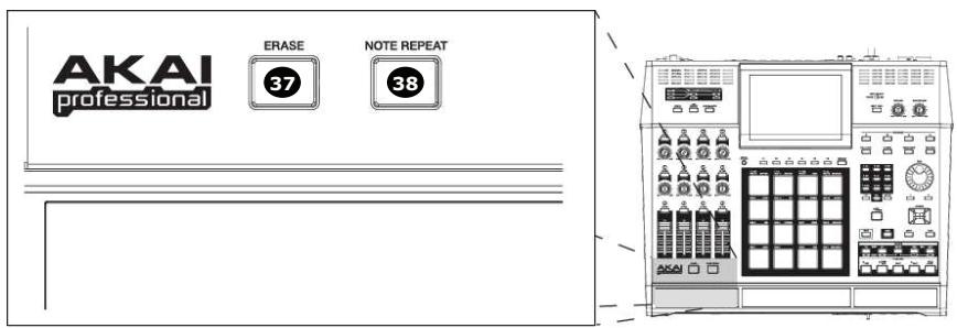
37. [ERASE] Button:
Use the [ERASE] button to delete events within a track. You can use this button in real-time during recording, or to delete events using the ERASE window. For more information see page 23.
38. [NOTE REPEAT] Button:
Holding this button down when you strike a pad causes the pad to retrigger the sample at a rate indicated in the 'Timing Correct' Window ([F1] (T.C.) on the MAIN page). Note Repeat allows for the playing of drum rolls, hi hat runs with varying amounts of swing, and other fast percussive effects not easily played by hand. For more information see the section entitled 'Note Repeat' on page 26.
![AKAI MPC5000 - [NOTE REPEAT] Button: - 1](/content/2025/01/152537/images/99159ec3da874f9e914a90ee9eca23cb386a1be20ea494cfafa35dd0d3586b74.jpg)
Front Panel
The MPC5000's front panel has several noteworthy features:
39. [MEMORY CARD SLOT]:
The MPC5000's [MEMORY CARD SLOT] accepts 'Type I' and 'Type II' Compact Flash memory cards. These cards are used to store your audio and song data.
40. [DVD ROM] drive (Optional):
Here, you can install an optional CD-RW/DVD ROM drive (Model #CDM-25). Using this DVD drive, you can load WAV, AIFF or SND samples from CD, sample from CDs, create data backups of your work, and record Redbook audio CDs to be played on any CD player.
41. [FOOTSWITCH] Jacks (2):
This is where you connect a momentary footswitch. You can use a footswitch for several functions, including punching in or out, starting and stopping the sequencer, or even playing selected pads. For more information, see 'Using the Footswitches' on page 176.
There are two types of footswitches: normal open (the contact is open when it is not pressed), and normal closed (the contact is closed when it is not pressed). When the MPC5000 is powered on, it automatically detects the type of foot switch connected, so you can use either type of foot switch.
42. [PHONES] Input:
Connect your stereo headphones to this jack. This jack mirrors the signal from the [STEREO OUT] jacks. The volume of the headphones is controlled by the [MAIN VOLUME] knob.
Rear Panel
All of the MPC5000's inputs and outputs can be found on the rear of the unit. They are as follows:

43. [STEREO OUT] Jacks:
These are your MPC5000's main outputs. Connect these jacks to your recorder, mixer, or speakers.
44. [RECORD IN] Jacks (1/4" / Mic Combo):
Use these inputs to record samples into your MPC, and record streaming disk tracks to the internal Hard Disk.
The [RECORD IN] jacks are 1/4" / Mic combo jacks, allowing either type of connector to be used. The input level for this jack is controlled using the [REC GAIN] knob.
45. [MIC/LINE] Switch:
This switch sets whether the source plugged into the [RECORD IN] is a mic level or a line level source. If set to MIC, the input will be preamped for optimal level.
WARNING! Incorrectly setting this switch to MIC will yield distortion on devices not requiring a MIC Preamp. Make sure your source requires amplification BEFORE setting this switch.
46. [PHONO IN] Jacks (RCA):
Use these jacks to connect a turntable or a CD player with RCA connections to your MPC. The input level for this jack is controlled using the [REC GAIN] knob. For best performance, be sure to set the [INPUT] phono/line switch properly.
47. [ADAT] Digital Out:
This output is used to connect ADAT capable digital devices. This connection uses an optical cable to send 8 tracks of ADAT digital audio to a recording device. For more information on configuring outputs, see page 176.
48. [DIGITAL IN/OUT] Jacks (S/PDIF):
These are the coaxial digital input/output. This IN is to connect digital outputs such as a CD player and a DAT. This OUT sends out the same signal as the [STEREO OUT].
49. [PHONO GROUND] nut:
If your turntable requires it, use this nut to connect the turntable ground wire.
50. [LINE / PHONO] Switch:
This switch determines whether the [PHONO IN] RCA jacks will be line or phono level. When set to PHONO, an RIAA-Class phono preamp will be applied to the input. Set this switch to the 'LINE' position, for sampling a line-level source (CD player, DJ mixer, Minidisk, etc.) and to the 'PHONO' position for recording with a turntable.
WARNING! Incorrectly setting this switch to PHONO will yield distortion on devices not requiring amplification. Make sure your turntable requires amplification BEFORE setting this switch.
51. [ASSIGNABLE MIX OUT 1/2/3/4/5/6/7/8] Jacks (1/4"):
These individual outputs can be used to output each pad sound separately, allowing you to send individual sounds to external mixers or effects. Using these outputs, you can perform advanced mixing for your songs.
52.[USB]Port:
This port allows you to connect your MPC to your computer to quickly transfer files using the high speed USB2 protocol. Connect your MPC5000 to a computer using a standard USB cable. See 'Connecting the MPC5000 to Your Computer' on page 173 for more about this port.
53. [Power] Switch:
This switch powers the unit on and off.
54. [AC IN] Jack:
Connect the power cable to this jack. This uses a standard IEC type power cable. The internal power supply is auto switching from 100 to 240 volts, 50 - 60Hz .
55. [MIDI] Jacks (2 IN, 4 OUT):
The MPC5000 can send and receive MIDI data through these jacks. Connect one of the MPC's outputs to the MIDI input of an external device and one of the MPC's inputs to an external device's output.
![AKAI MPC5000 - [MIDI] Jacks (2 IN, 4 OUT): - 1](/content/2025/01/152537/images/420f080e16a4ea1acba84d90aa54c3c5f7ea043c8981c4ef479350a77ef0d2d3.jpg)
Bottom Panel
56. Ram Expansion Slot:
This is where the optional EXM-E3 RAM expansion module can be added. This will increase overall sample time to over 36 minutes (mono), of which a single sample can be over 24 minutes long.
Hooking Up Your MPC5000
The following diagrams will demonstrate how the MPC5000 can be integrated into your recording setup. Note that the diagrams below use every connector on the MPC and that your setup may vary from the ones shown.
Output Connectivity Example
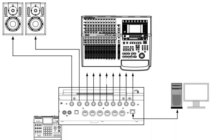
- Connect the [STEREO OUT] to Powered Monitors
This will allow the main mix of your MPC to be heard.
- Connect the [ASSIGNABLE MIX OUTS] to a multi-track Hard Disk recorder.
This will allow individual samples and sounds to be sent individually to be recorded.
Other examples of ways you can connect your MPC5000's outputs include connecting the [STEREO OUT] to a mixing board to mix the MPC alongside other instruments, and using the [ASSIGNABLE MIX OUTS] to send certain sounds to external effects processors.
Note: The MPC5000's outputs are pseudo balanced. Use 'Balanced' or 'TRS' cables wherever possible to maximize sound quality, but no volume degradation will occur when using standard 'TS' type cables.
■ Analog Input Connectivity Example
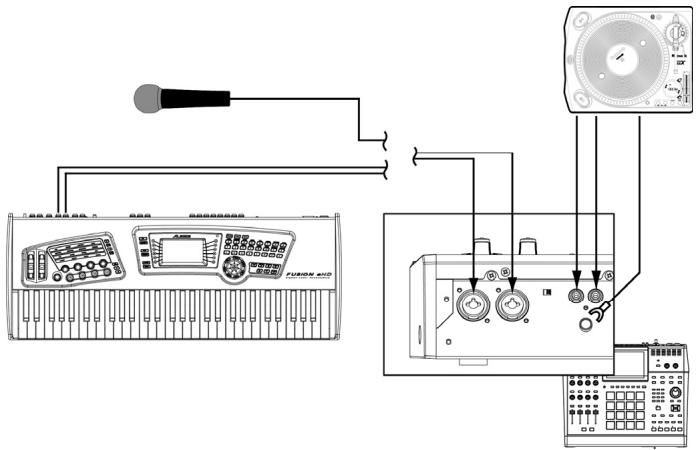
- Connect a synthesizer or a Microphone to the [RECORD IN] jacks.
Sources plugged into the [RECORD IN] jacks can be sampled to be used in Sample Programs. The [RECORD IN] jacks are 1/4'' / Mic combo jacks, allowing either type of connector to be used. The input level for this jack is controlled using the [REC GAIN] knob.
Input sources can be monitored using the Input Thru feature. See page 82 for more information. Additionally, these sources can be used for Hard Disk Recording. See page 61 for more information on Hard Disk Recording.
NOTE: The input sensitivity of these jacks are determined by the [LINE/MIC] switch. Setting this switch incorrectly can cause clipping and distortion. Be sure to determine whether your source is line level or mic level before connecting your device
- Connect the output of a turntable to the [PHONO IN] jacks.
This will allow sampling from vinyl. If your turntable requires a preamp, make sure the [LINE/PHONO] switch is set to 'PHONO'. If the turntable requires grounding, connect the grounding wire to the [PHONO GROUND] nut.
WARNING! Incorrectly setting this switch to PHONO will yield distortion on devices not requiring amplification. Make sure your turntable requires amplification BEFORE setting this switch.
Digital Connectivity Example
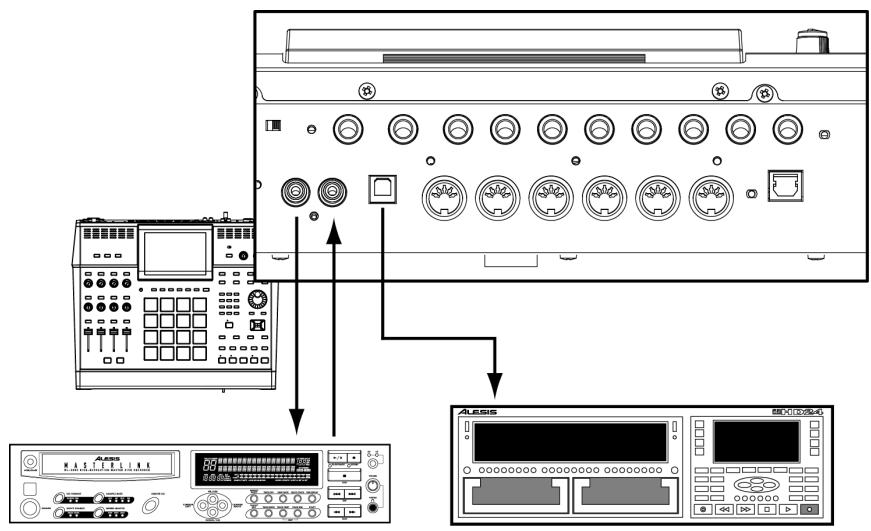
- Connect the [DIGITAL IN/OUT] jacks to a digital recorder
This connection is a 48kHz S/PDIF type digital audio signal.
NOTE: The S/PDIF jack on the back of the MPC5000 looks like a standard RCA connector, but you should not use ordinary audio cables for this connection. S/PDIF requires special 75-ohm 'digital audio' cables to work properly and will most likely result in very loud white noise if you use the wrong type of cables. If you're hearing clicks, pops, or white noise when using S/PDIF, your cable is the likely culprit.
- Connect the [ADAT] output to a Digital Recorder.
This optical digital output supports 8-channel ADAT format. See 'Setting the ADAT Digital Output' on page 176 for more information on configuring ADAT output.
USB Connectivity
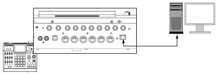
To connect your computer to the MPC5000, use a standard USB cable.
For more information on USB mode and connecting your MPC5000 to your computer, see 'Connecting the MPC5000 to Your Computer' on page 173.
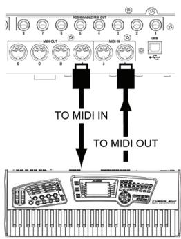
■ MIDI Connectivity
To connect your MIDI devices to the MPC5000, do the following:
- Connect the MIDI output of your MIDI device to one of the [MIDI IN] ports of the MPC5000.
- Connect the MIDI input of your MIDI device to one of the [MIDI OUT] ports on the MPC5000.
For more information on connecting MIDI devices to your MPC5000, see 'Using the MPC5000 with External Devices' on page 167.
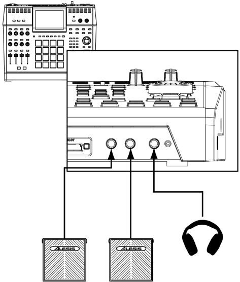
Footswitch / Headphone Connectivity
- Connect a footswitch to each [FOOTSWITCH] jack
Footswitches will allow you to start and stop your MPC, punch out, or do many other functions. See page 176 for more information.
- Connect headphones to the [PHONES] input.
This will allow you to monitor the output of the [STEREO OUTS]. The level of the headphones is controlled with the [MAIN VOLUME] knob.
Basic Concepts and Terminology
Please take a moment to familiarize yourself with the following terms and concepts since you'll encounter them throughout this manual.
Sequence
A sequence is the most basic 'building block' of music you can compose on the MPC. MIDI information from the MPC's pads, buttons, and Q-LINK controls (or an external keyboard) are recorded to tracks within a sequence. Each sequence has 64 tracks and the MPC5000 can hold up to 99 separate sequences at one time.
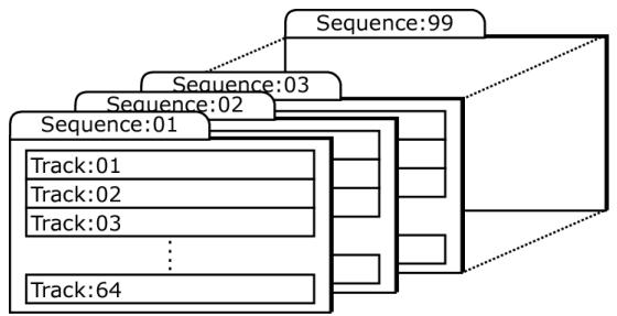
The length of a sequence can be set from 1 to 999 bars and you can theoretically create an entire song using only one sequence. However, the MPC has a special SONG mode that lets you arrange several short sequences together to create a song. This allows you to create a sequence for each section of your song and to arrange and rearrange these sections however you'd like.
For example: by creating a separate sequence for the verse, chorus, and hook of a song, you can use Song mode to quickly arrange the verse, chorus, and hook in any order you'd like. This saves you from having to repeat the same section (such as the chorus) many times throughout the song. More importantly, SONG mode makes editing and rearranging your song easy since you can simply change the order of sequences (or number of repetitions for each sequence) instead of re-recording the entire song.
Song mode is also where you can record audio tracks directly to the Hard Disk. This will be discussed further later on.
Tracks
The MPC 5000 has two types of tracks - sequence tracks and Hard Disk recording tracks. Sequence tracks are found within sequences. A sequence has 64 tracks and each track can record a performance. For example, you can record the verses for a song on track one while recording the choruses on track two. Alternatively, you can record different instruments on each track.
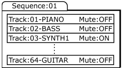
Note that your performances are recorded as MIDI events and the actual digital audio is not recorded onto a track. Because of this, you can edit your performance many different ways once the performance has been captured. See the section below entitled 'Note number, velocity, and length' below for more this.
Hard Disk recording tracks are recorded in song mode. Using Hard Disk recording, you can record a live performance, such as vocals or guitar, and have these tracks play back with your song. The MPC5000 can have up to eight Hard Disk tracks. Two can be recorded simultaneously.
Song
As we stated above under the 'Sequence' description, the MPC has a special SONG mode that allows you to arrange different sequences together to form a song. Each time a new sequence is added to a song, we say a new 'step' is created within the song. You can use song mode to arrange different sections (verse, chorus, hook, etc.) of a song together.
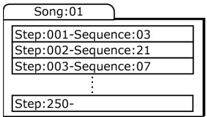
Songs are created and arranged in the MPC5000's SONG mode. Each song can have up to 250 steps and the MPC5000 can hold 20 songs at one time. See 'SONG Mode' on page 55 for more information about this mode.
Song mode is also where you can record audio tracks directly to the Hard Disk. This will be discussed further later on. See HD RECORD on page 61 for more information.
Sample
When you tap the pads on the MPC5000, you trigger various different sounds that we call 'samples.' Samples are digitized snippets of audio that can be recorded using the [RECORD IN], [PHONO IN] or [DIGITAL IN] on the rear of the MPC, loaded from a memory card, CD-ROM, internal Hard Disk, or transferred from a computer (via the USB port).
Once a sample is loaded or recorded into the MPC5000, it can be manipulated in different ways. For example, a sample can be trimmed down in length, looped, pitch-shifted or processed using one of the various effects found within the MPC. When you are finished editing your sample, you can assign it to one or more drum pads so that you can play the sample with those pads.
The MPC5000 supports 16-bit samples at any sample rate (audio imported at sample rates higher than 44.1k is automatically downsampled down during playback). Samples can be either mono or stereo.
Drum Pad
The MPC5000 has 16 pressure sensitive pads that are used to trigger sounds. These pads are arranged in 4 banks called 'A,' 'B,' 'C,' and 'D.' These banks can be quickly selected using the [PAD BANK] buttons giving you easy access to 64 different sounds. Use PROGRAM mode to assign samples to these pads.
Sample Program
A Sample Program is a file that contains a list of all samples to be used, and settings for each sample (i.e., pad assignments, loop points, pitch tuning, effects, etc.) The MPC's PROGRAM mode is where you can edit and assign samples. The MPC5000 can have a total of 100 programs in memory total.
| Program:01 | |
| Pad bank Pad Sample Level, Pan, Filter... | |
| A 01 Side Stick | |
| A 02 Bass Drum | |
| A 03 Closed Hihat | |
| ... | |
| D 16 | |
Synth Programs
Synth programs (short for 'Synthesizer') are new to the MPC5000. The concept of a Synth is an instrument that is capable of producing a very wide range of sounds electronically. Synths have been the basis of popular music since the late 60's, across just about every genre of popular music. Browsing and playing through the included Synth Programs will give you an idea of the vast variety of sounds that Synth Programs are capable of producing.
Note Number, Velocity, and Length
When you are recording a sequence, every time you tap a pad, three key pieces of data are recorded on a track:
The note number (i.e., which pad you struck)
The note velocity (i.e., how hard you struck the pad)
The note length (i.e., how long you held the pad down)
Once this information is recorded, the MPC can playback your performance exactly as it was recorded. You can also do things like edit or delete notes, overdub (add) more notes to an existing performance, tighten up your timing through the Timing Correct feature, and much more. These various functions are covered in detail in 'The Sequencer' on page 19.
If you are familiar with MIDI sequencing, the terms and concepts described above may already be familiar to you. If you're new to MIDI sequencing, don't worry—the MPC5000 handles most tasks automatically. All other tasks that require user input are covered throughout this manual.
RAM
RAM (Random Access Memory) is a space where you can temporarily load audio and MIDI (song) data. The MPC5000 ships with 64MB (megabytes) of RAM and can hold about 768 seconds (over 12 minutes) of mono sound. The EXM-E3 expansion module raises your memory to 192MB and increases your total recording time to over 36 minutes.
Note that RAM contents are deleted when the MPC5000 is turned off. If you wish to keep your work, you must save your work on either a memory card, or the internal Hard Disk.
Memory Card
Compact flash memory is similar to RAM, except that the information stored on a compact flash memory card is not lost when the MPC5000 is turned off. The MPC5000 ships with a compact flash memory card on which you can store your work.
Note that the MPC5000 cannot play your songs or sample data directly from a memory card. Your data must first be loaded into RAM memory before it can be played.
About Memory Cards: There are several types of memory cards available today. The MPC5000 supports 'type I' and 'type II' compact flash cards only, so please make sure you purchase the correct type of card.
Operating Modes
The MPC5000 has several different modes of operation. Each of these modes handles specific tasks such as arranging your sequences (SONG mode) or recording your own samples (REC SAMPLE mode).
Each mode can be accessed using the MPC5000's drum pads. To enter these modes, hold the [MODE] button and tap the pad associated with the mode you want. The name of each mode is listed in yellow at the upper right of each pad.
MAIN Mode ([MAIN])
This is the start page of the MPC5000 and is displayed when the unit is powered on. Use this mode to record your sequences. Should you get lost, pressing the [MAIN] button will always return you to this page.
Q-LINK Mode ([MODE] + [Pad 1])
Here, the function of the Q-LINK slider can be set. Various real-time performance data can be recorded and entered here, as well as sending MIDI continuous controllers to external modules.
DISK Mode ([MODE] + [Pad 3]).
Here, you can access the various storage media available to you. This is where files, such as samples and sequences, can be saved, or retrieved and edited.
![AKAI MPC5000 - DISK Mode ([MODE] + [Pad 3]). - 1](/content/2025/01/152537/images/8d7370b325d5e2fab6918a9ec0e035ae9686b0cc6bd2f3a0066e97f8d18810fd.jpg)
■REC SAMPLE Mode ([MODE] + [Pad 4])
Here is where you can record your own samples for playback on the MPC5000's pads.
TRIMMode([MODE]+[Pad5])
This is where you can edit individual samples, deleting silence, adjusting overall volume of recorded samples and so forth.
■ PROGRAM Mode ([MODE] + [Pad 6])
Depending on if the type of program is Sample or Synth, this page will allow individual samples to be assembled into a group for playback on the individual pads, or allow editing of a Synth program's virtual analog parameters.
■MIXER Mode ([MODE] + [Pad 7])
This mode is where the mixing of individual pads or complete sequencer tracks can be done graphically, much like using an external mixing board. Which output the signal is sent to, and what effect bus and how much effect is used per sound is also determined here.
■ MIDI/SYNC Mode ([MODE] + [Pad 8])
Here, you can sync up your MPC5000 with other devices, and control different aspects of MIDI.
OTHER Mode ([MODE] + [Pad 9])
Here, you can find different settings that don't fit easily into other categories, such as Master level, pad sensitivity, etc.
ARP Mode ([MODE] + [Pad 10])
This mode allows you to edit the Arpeggiator. This is mode can also be edited by pressing the [ARPEGGIATOR] button. For more on the Arpeggiator, see page 129.
■ EFFECTS Mode ([MODE] + [Pad 11])
This is where different digital effects, such as reverb, delay and flange can be applied to different pads etc. Also, master effects, such as parametric EQs and compression can be applied to the Master output.
SEQEDITMode([MODE] + [Pad12])
This is where sequences can be edited and transposed, as well as other types of editing.
STEPEDITMode([MODE]+[Pad13])
Here, the sequence can be edited with greater precision, editing the parameters of individual notes and events.
GRID EDIT Mode ([MODE] + [Pad 14])
'GRID EDIT' mode allows you to edit the individual note and pad events on a track in a graphical interface. This mode is ideal for fine editing of different tracks in a sequence visually.
■ SONG Mode ([MODE] + [Pad 15])
Here is where individual sequences can be organized into a single song.
HD RECORD Mode ([MODE] + [Pad 16])
This brings you into HARD DISK RECORDING MODE. Here, performances, such as vocals, guitar, or other live instruments can be recorded directly in to and played from the internal hard drive alongside the current song.
SYNTH Programs ([SYNTH])
Pressing the [SYNTH] button will quickly bring you to the first synth track in your sequence, bring you to the last synth program you edited, or create a synth program on a new track. It's best to think of the [SYNTH] button as a quick-fix shortcut to quickly get into synth programming. This mode can also be entered by selecting a track on the MAIN page that uses a Synth-type program, and entering PROGRAM mode.
Chapter 2: Basic Operation
In this chapter, we will describe the basic operation of the MPC5000.
MAIN Page
This is the main screen of the MPC5000, where you record and play back sequences. You can go back to this page at any time by pressing the [MAIN] button. If at any time you get lost while operating the MPC5000 and want to go back to this page, simply press the [MAIN] button. You cannot go back to the MAIN page by pressing [MAIN] button while processing (e.g. Recording, loading/saving etc...).
Cursor, Cursor Buttons, [DATA] wheel
The highlighted reverse colored square on the screen is called the 'Cursor'.
You can move the cursor on the screen using the four [CURSOR] buttons on the panel. Usually they move to specific locations such as to the right of a colon (:). Those locations are called 'fields', and will be indicated in the manual by single quotes. This is where you can make various settings, or enter values. To change the settings of a field, select the field and turn the [DATA] wheel on the panel. This operation, selecting a field by using a cursor button and changing its settings with the [DATA] wheel, is the most basic operation of MPC5000.
![AKAI MPC5000 - Cursor, Cursor Buttons, [DATA] wheel - 1](/content/2025/01/152537/images/139e843be8b48a1b1c8a2d0bee2e11652aa70172b869938feb4f1f1d58bd5ba1.jpg)
![AKAI MPC5000 - Cursor, Cursor Buttons, [DATA] wheel - 2](/content/2025/01/152537/images/c48c50f692f69af34d9186846efffcc8377619805147fcf928badf674f2f4692.jpg)
Function Buttons
Six buttons ([F1] to [F6]) aligned under the LCD (liquid crystal display) are Function Buttons. Those buttons correspond to each of the six functions that are displayed on the bottom of the LCD. Pressing each button activates its corresponding function. The function that each button represents depends on where you are.
When the LCD looks like this, pressing a function button starts some processing or displays a window.
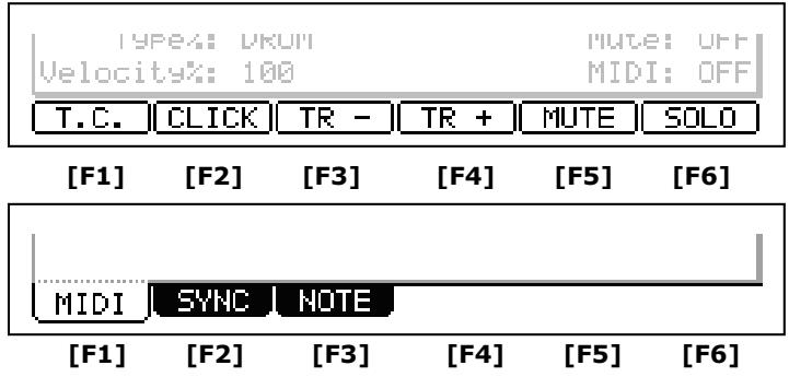
When the LCD looks like this, you can switch pages using function buttons [F1] to [F3]. The currently selected page is displayed with white letters on a blue background. Pressing F4, F5 and F6 buttons does not make any changes.
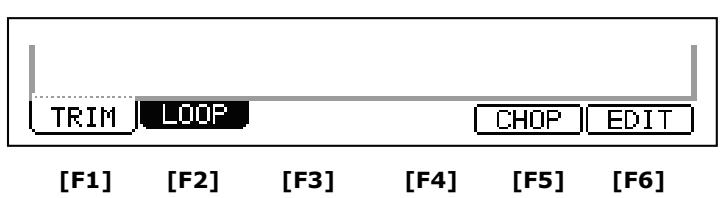
Some pages display the page selection and processing function at the same time (see below). In this case, use [F1] and [F2] for switching pages, and [F5] and [F6] for activating processing. You cannot use [F3] and [F4].
In this manual, function buttons are described something like this: '[F1] (TRIM) button'- in the bracket, it shows the function displayed on the LCD.
■[WINDOW]Button
The MPC5000 has so many functions that they cannot be displayed in one screen. For efficiency, each page only displays the most frequently used functions. If you want to make an advanced setting, press the [WINDOW] button. This opens a window for the detailed setting of the selected field. This is not available for all fields. When you select a field in which you can use the [WINDOW] button, the LED of the button is lit.
[MODE]Button
With the MPC5000, each function (such as recording samples, editing samples, assigning samples to each pad, editing sequence data, loading from memory cards, etc...) has a separate screen. These screens are called 'modes'. For example, you will use the RECORD mode to record samples, and the TRIM mode to edit samples etc. By pressing the
[MODE] button and hitting a pad, you can switch modes. The mode that a pad corresponds to is displayed above each pad.
Setting Names
The MPC5000 handles various types of data, from sound data (such as samples and programs) to performance data (such as sequences and tracks). This data is managed by naming. In this section, you will learn how to name these items.
Select a field which you wish to name with the cursor and turn the [DATA] wheel. The Name windows will appear.
Note: In this window, the cursor is displayed as an underscore instead of highlights.
You can enter the name, either by using the keypad or by using the [DATA] wheel.
■ Entering letters with [DATA] wheel
You can change letters selected with a cursor by turning [DATA] wheel in the Name window. Move the cursor with RIGHT/LEFT cursor button and enter letters. You can enter letters using both [DATA] wheel and pads.
■ Entering letters with the Numeric Keypad
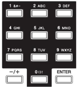
Much like a telephone, three or four letters are assigned to each number on the keypad. By hitting a number, the corresponding letter is entered. Below, we will describe how to enter 'Bass 01' instead of 'Sequence 01'.
- Press the UP cursor button to make the first letter capitalized.
Pressing the UP cursor button allows you to enter a capitalized letter.
- Hit [2] two times.
Hitting [2] once enters 'a', twice enters 'b', three times enters 'c', four times enters '2'.
- Press the RIGHT cursor button and move the cursor to the right.
If you enter the next letter using a different button, the cursor will move to the right automatically. However, when you enter the letters which are assigned to the same button, you need to press the [RIGHT] cursor button to move the cursor manually. In this example, A and B are assigned to the same button. So, you need to move the cursor manually.
- The next letter is a lower-case letter ('a'), so press the [DOWN] cursor button.
Pressing the [DOWN] cursor button allows you to enter lower case letters.
- Hit [2] once.
A lower case letter 'a' is entered.
-
Hit [7] four times. The cursor will move to the right automatically and a lower-case 's' is entered.
-
Press the RIGHT cursor button to move the cursor to the right and hit the [7] four more times.
This will enter a second 's'.
- Press the RIGHT cursor button to move the cursor to the right and press RIGHT cursor button holding the [SHIFT] button.
The [SHIFT] + RIGHT cursor button inserts space.
-
Press the right cursor button to move the cursor one step to the right, and press the '0' button four times to insert a zero.
-
Press the '1' button four times.
-
Press the RIGHT cursor button to move the cursor to the right, and press the LEFT cursor button four times holding the [SHIFT] button.
The [SHIFT] + LEFT cursor buttons delete selected letters. Now 'Bass 01' is entered instead of 'Sequence 01'.
- Press [F5] (ENTER) to confirm the entry and close the window.
Pressing [F4] (CANCEL) cancels the entry and closes the window. In this case, the name does not change.
Chapter 3: The Sequencer
The MPC5000 has a sequencer feature that allows you to record/playback your performance. With the sequencer feature, you can record the performance you created with the pads, and by playing back the recorded data, you can reproduce your performance. The actual performance will be recorded on a track within a sequence. For more information on sequences and tracks, see the section entitled 'Basic Concepts and Terminology' on page 13.
The performance data you made by hitting the pads will be recorded on a track as events A track can contain other events, such as Q-LINK controller information, tempo change etc... When you are using the MPC5000 with an external MIDI device, you can record the data from the external keyboard as MIDI events.
Note: The sequencer feature records only performance data (when and which pad you hit, etc...). It does not record the actual sound. To record audio tracks, see 'HD RECORD' on page 61.
Main Page
This is the page where you record/playback sequences. This is the MPC5000's main operation mode and, unlike the other pages, you can display this page by pressing the [MAIN] button at any time.
Now
The 'Now' field, which is located in the upper left corner of the screen. When you record/playback a sequence, the display updates constantly to show the current position of the sequence. When the sequence is stopped, you can move the cursor to the 'Now' field to set the time manually.
The 'Now' field displays time in two ways.
Bars and Beats
Bars and Beats will display the current time of the sequence by bar, beat and tick from left to right. For example, '002.03:000' means the third beat in the second bar. When you record/playback a sequence, the display updates constantly to show the current position of the sequence.
A tick is a unit that divides a beat (1/4 note) into 960 parts. For example, 1 beat equals one 1/4 note (960 ticks), so one 1/8 note equals the half of 1 beat, which is 480 ticks.
Now: 024.02.758
Sequence: CDS
Below is the relationship between note and tick:
1/4 note = 960 ticks 1/8 note = 480 ticks 1/16 note = 240 ticks
1/4 triplets = 640 ticks 1/8 triplets = 320 ticks 1/16 triplets = 160 ticks
1/32 Note = 120 ticks 1/32 triplets = 80 ticks 1/64 note = 60 ticks
1/64 triplets = 40 ticks
Absolute Time
Another way the 'Now' field will display time is absolute time. Absolute time will show actual length of the sequence in hours, minutes, seconds, and frames. For example, '00h03m07s03f means three minutes, seven seconds, and three frames. Unlike when displayed in BARS:BEATS:TICK, the 'Now' field will increase in time linearly as a sequence plays. In other words, If you have a two bar sequence, and you let it play for 5 minutes, BARS:BEATS:TICK will show the time counting to bar two, then looping back to one, but viewing the HOURS:MINUTES:FRAMES display will count up to '00h05m00s00f showing the sequence played for five minutes.
Frame is a subdivision of seconds sent via MIDI in a format called MIDI TIME CODE, or MTC. MTC is a standard that has been used as a timing standard for many years by both the Audio and the Video industry. The MPC5000 can sync to the frame rate of external devices, or generate its own timing data to slave other devices to its internal clock. For more on MIDI TIME CODE, see page 168.
To toggle between 'Bars and Beats' and 'Absolute Time', do the following:
- In MAIN Mode, select the 'NOW' field as shown.
Now: 881.81.888
- Scroll with the [DATA] wheel, or press the [+] button.
- The screen will change as shown.
Now: 08h08m08s08f
Sequence
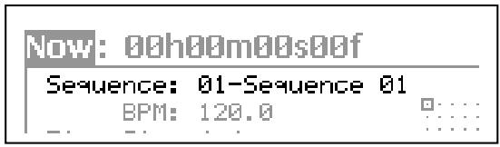
A Sequence is the most basic unit when you create data with the MPC5000. Performance data from the MIDI keyboard or pad can be recorded on each track within a sequence. You can select a sequence in this field by turning the [DATA] wheel, or typing in a number with the [NUMERIC KEYPAD]. The MPC5000 can have up to 99 sequences in memory at any one time. Empty sequences are indicated as
unused). All the settings in the MAIN page can be set separately for each sequence.
Track' field
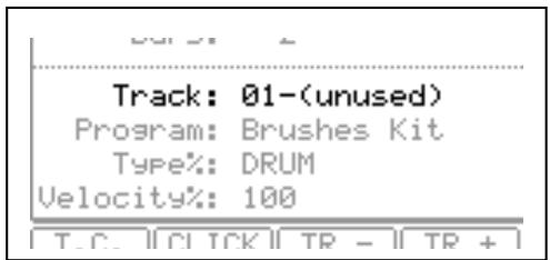
A sequence has 64 tracks. You can record different parts separately to each track. You can, for example, record Piano sounds on track 1, Bass on track 2, Organ on track 3 etc... In the 'Track' field, you can select a track within the sequence selected in the 'Sequence' field. An unused track is indicated as (unused). You can set 'Mute', 'MIDI', 'Velocity%', 'Type', and 'Program' fields separately for each track.
Track Status' field
The 'Track Status' field shows a small representation of each of the 64 tracks in the current sequence. When an event is played on each track, the track indicator for that particular track will blink. The Square box indicates which track is currently active in the 'Track' field. Using the 'Track Status' field, you can find stray notes on tracks and visually see where each event is happening.
Also, tracks set as Continuous Sample Tracks will be displayed as a "+" symbol. For more on Continuous Sample Tracks, see page 34.
Recording the Performance
In this section, you will learn how to record the performance you made with pads to tracks in a sequence.
- To record your performance data to a sequence, you need to load a program to the MPC5000. By default, the MPC5000 automatically loads preset programs and demo sequences from the internal ROM. Here, we assume that you have already loaded a program to the MPC5000. If you have not done so, do this now by loading a program from a memory card, or by recording a sample and assigning it to a pad, etc... For more information on loading a program, see the 'Saving and Loading (DISK Mode)' section on page 149. For more information on recording a sample, see the 'Sampling' section on page 83.
- Press the [MAIN] button to open the MAIN page.
The [MAIN] button displays the MAIN page where you record your sequences.
- In the 'Sequence' field, select a sequence to which you wish to record your performance.
You can select any sequence for recording a performance, but here, select a sequence that says 'unused'.
'Unused' indicates that the sequence is not used.
- Select the 'TRACK' field and select an unused track.
Your performance will be recorded on the track you select in the 'Track' field. You can select any track, but here select the first unused track (i.e. '01-(unused)'.
- In the 'Program' field, select the program to play.
Select the 'Program' field, and scroll with the [DATA] wheel until the desired program is displayed.
You can select any program currently in RAM in the 'Program' field by turning the [DATA] wheel.
- Hit pads to check the sounds that are assigned to the pads.
This will play the program selected in the 'Program' field.
- Press the [PLAY START] button while holding the [REC] button.
The recording will start after 4 counts.
- Play the pads to record your performance.
By default, the sequence is set to 2 bars. After recording for 2 bars, the MPC5000 will start playing back the recorded performance. You can add to your original performance by continuing to play the pads when the track loops. The MPC5000 automatically switches to 'overdub' recording and adds to the performance.
- Stop overdub recording by pressing [STOP] button.
- Press the [PLAY] button to play your recorded performance.
- If you do not like the performance, you can start a new recording by pressing the [PLAY START] button while holding the [REC] button.
This deletes the previously recorded performance data and starts a new recording.
- To add to the already recorded performance, press the [PLAY START] button while holding the [OVERDUB] button.
This will play back the currently recorded performance, and you can add the new performance by playing the pads.
Tip: If you select another sequence in the Main page, you can record a new performance separately. By playing back those sequences, you can create an entire song.
Tip: By default, the MPC5000 is set to load a demo sequence automatically when you turn it on. If you wish to remove the demo sequence and start from scratch, see 'Deleting All Sequences' section on page 30.
Record Ready Mode
New to the MPC5000 is 'Record Ready' Mode. When only the [REC] button is pressed and released, the RECORD light will blink, indicating that the MPC5000 is in 'Record Ready' Mode. The MPC5000 will now wait for a MIDI START command.
To use Record Ready mode, do the following.
- Press and release the [REC] button.
The MPC5000's RECORD light will blink, indicating it is now in 'Record Ready' Mode.
- When you are ready, press 'Start' on the master device.
Recording will start.
Step Recording
The MPC5000 allows step recording right from the MAIN page. When you hit a pad, or when the MPC5000 receives MIDI data from an external device, the MPC records the event in the current time position (the time displayed in the 'Now' field). With Step Recording, you can move to the desired time position by setting the time position in the 'Now' field, and you can add events to the desired time position one by one. This method, recording each event individually when MPC5000 is in the stop mode, is called step recording. This function allows for complex passages to be recorded with ease.
To Step Record from the MAIN page, do the following:
- Stop the current sequence if it is running.
- Set the NOW to the time you would like to insert notes
- Press and hold the [REC] or [OVER DUB] button.
- The MPC is now in STEP RECORD Mode for as long as [REC] or [OVER DUB] is held.
- Play a pad.
The MPC will record the note played in the current position. There are several options you can set to fine tune your STEP RECORD performance. Step Recording from the Main Page shares settings with STEP EDIT. For further information on STEP EDIT, see page 43.
Playing Back a Sequence
You can play back a recorded sequence by pressing the [PLAY START] button. The sequence will be played repeatedly until you press the [STOP] button. If you press the [PLAY] button again, the MPC5000 will resume the playback from where the previous play back was stopped.
■ Playing Several Sequences in Series
You can play back several sequences in a series by using the Next Sequence feature. The Next Sequence feature allows you to select the next sequence to play, while playing back a sequence, so that you can play the sequences in a series.
While a sequence is playing, you can select the next sequence to be played from the Main page by turning the [DATA] wheel or using the numeric keypad at the 'Sequence' field.
-
From the Main page, select a sequence and press [PLAY].
-
While the selected sequence is playing, change the 'Sequence' wheel. The screen will change as follows:
The 'Sequence' field continues to show the sequence number that is currently playing,
The >^ field shows next sequence that will be played.
- After playing back the currently selected sequence to the end, the MPC5000 will start playing back the sequence you've selected. By repeating this step, you can play back several sequences seamlessly.
When next sequence is selected, you can start to play next sequence immediately by pressing [STEP>] button.
When next sequence is selected, you can cancel selected next sequence by pressing [<STEP] button.
field to another sequence using the [DATA]
| Now: 002.03.405 >22-Chorus | |
| Sequence: 01-First Verse | |
| BPM: 120.0 | □: |
| Time Sis: 4/4 | □: |
| Bars: 4 | Loop: ON |
| Track: 01-Kick&Rim | |
| Program: Hip Hop Set | |
| Type: DRUM | Mute: OFF |
| Velocity%: 100 | MIDI: OFF |
| T.C. |CLICK | TR - | TR + | MUTE | SOLO | |
Tip: With the [NEXT SEQ] button, you can select the next sequence with a pad. For more information, see the 'Selecting a sequence with pads' section on Page 75.
Tip: In SONG mode, you can set the order to play sequences. For more information, see the 'SONG mode' section on Page 55.
Punch In/Punch Out
You can start the recording in the middle of the sequence during the playback ('Punch In').
You can also stop the recording in the middle of the sequence and resume the playback ('Punch Out'). This is useful when you re-record part of the recorded sequence.
Punch In
Press the [PLAY] or the [PLAY START] button to play back a sequence. At the point where you wish to start the recording, press the [PLAY] button while holding the [REC] button. The MPC5000 will start recording.
If you press the [PLAY] button and the [OVERDUB] button instead, the MPC5000 will start the overdubbing.
Punch Out
If you press the [REC] or the [OVERDUB] button during the recording/overdubbing, the MPC5000 will stop the recording/overdubbing and resume the playback.
Other Useful Features for Recording Sequences
Undo and Redo
When overdubbing sequences, you can cancel the last recording and reset to the setting before the recording.
- During recording, press [STOP]
Undo will only work when the sequence is stopped.
- Press the [UNDO] button.
The LED of the [UNDO] button will be off and only the last added recording will be deleted. To restore the last recording, press the [UNDO] button again to light the LED.
Note: You can use the [UNDO] button only for the last recording.
Tips: The MPC5000 is the first MPC to be able to undo and redo sequence recordings while the sequence is playing. This allows you to actively audition the recording while the sequence plays to decide if you wish to keep the last recording.
Erase
You can delete a certain pad performance by using [ERASE] button. There are two ways to use this feature: by deleting in real-time during overdub, or by selecting a pad and part to delete in the Erase page.
- Deleting In Real Time
- Press [PLAY START] and [OVERDUB] to start overdub recording.
- Press the pad you wish to delete while holding down the [ERASE] button.
While the [ERASE] button is held, pressing a pad will not record the pad, but delete any instances of the pad while it is being held down.
- Deleting From the Erase Screen
Performance data will be recorded in a track as an event. In the Erase window, you can select specific events in a track to delete.
- Press the [STOP] button to stop the sequence.
- Press the [ERASE] button.
- Select the track you wish to delete events from in the 'Track' field.
This field will default to the current track, but can be switched to any of the 64 sequence tracks. To erase events from ALL Tracks, scroll to '00-ALL TRACKS'.
- Select the range of time you would like the selected events from
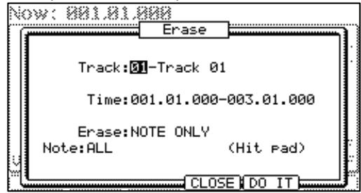
This will default to the entire length of the sequence, but you can set this to any range you wish. For example, to delete only the event in the first bar from 2-bar sequence, set '001.01.00 - 002.01.00'. In this case, the event at 002.01.00 point will not be deleted.
If you set the end point '002.01.00' like this, the area right before the end point will be included in the area.
- In the 'Erase' field, select the type of events to be deleted.
This will default to 'ALL EVENTS', but for this example, select NOTE ONLY.
The following are also available:
EXCEPT NOTE EXCLUSIVE
PITCH BEND EFFECT
CTRL CHANGE TEMPO
PRG CHANGE REAL TIME
CH PRESS TRACK MUTE
POLY PRESS
With CTRL CHANGE, POLY PRESS and REAL TIME you can be even more specific, selecting individual controller numbers or erasing poly pressure events associated only with a certain note.
- Select the 'Note/Pad' field.
This field will default to PADS or NOTES, depending on the track type. ALL is selected in the 'Value' field as the default. While Pads is selected on 'Parameter' field, you can select individual pads in the 'Value' field by hitting the specific pads you would like to delete directly. You can also select a pad with the [DATA] Wheel.
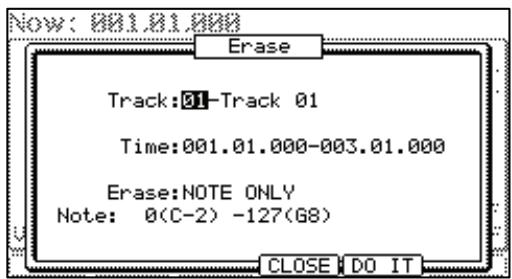
If the selected track is a MIDI type track, instead of DRUM, this field will display Notes as follows:
0(C-2)-127(G8)
The field for 'Notes' consists of two parts, Low note and High note. Low note (left) sets lower range of MIDI note and High note (right) sets high range of MIDI note. In this page, you can set note range with an external MIDI keyboard. The range is updated whenever a MIDI note is received.
For example, when the MPC5000 receives only one note, such as C 3, the range is set to C 3-C 3. When MPC5000 receive multiple notes, for example C 3, D 3 and E 3, then the range is set to C 3-E 3.
If you wish to delete all events, leave it as ALL. To delete only events on a specific
pad, hit the pad to delete. You can select several pads. If you hit a different pad by mistake, you can cancel the selection by hitting the pad again. To restart the pad selection, turn the [DATA] wheel to the left. The value in the Note field will be reset to ALL so that you can select pad from the beginning.
- Press [F5] (DO IT).
The operation starts and the events of the selected pad within the selected area will be deleted.
Erase can also be used to delete events from tracks other than the currently selected track, or to delete only specific types of events. You can also specify only a certain time range from which to delete events.
Tip: When you delete events with the Erase field set to ALL EVENT, the MPC5000 will delete other events in the selected area as well as pad events. When you delete events with the Erase field set to EXCEPT Note, the MPC5000 will delete the other events other than the pad events in the selected area.
Timing correct
When recording a pad performance, it is hard to play the pads to the tempo. By using the timing correct feature, you can correct the timing of the pad event you recorded by hitting pads. There are two ways to use this feature: by correcting the timing in real time during the recording, and by correcting the recorded event after the recording.
Real time timing correction
You can correct the timing in real-time during the recording.
- When a sequence is playing, press [F1] (T.C.) button in the MAIN page.
The Timing Correct window will be displayed as shown on the right.
- In the 'Note Value' field, set the value for timing correction.
For example, if you set '1/16', each position of the performance data will be moved to the nearest 1/16 note.
You can set the Note values as follows.
1/4 note
1/8 note
1/16 note
1/4 triplets
1/8 triplets
1/16 triplets
1/32 Note
1/32 triplets
1/64 note
1/64 triplets
OFF
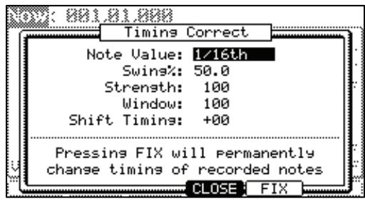
Tip: If you press [F1] (T.C.) button during recording/playback, a small Timing Correct window will be displayed while you are holding the button. You can use the 'Note value' field of this window to change the value for timing correction. It makes it easier to change the value during the recording.
Swing
You can set the swing value in the 'Swing%' field. With the swing feature, the even numbered events set in the 'Note value' field will be off the rhythm according to the value in the 'Swing%' field. With this feature you can create the shuffle groove.
- Press [F4] (CLOSE) button.
This closes the window.
Tip: Thanks to an ultra-high sequencer resolution of 960 pulses per quarter note, the MPC5000 is the first MPC to be able to apply MPC Style SWING to triplets.
Correcting the timing of recorded events
You can correct the timing of recorded events.
- When a sequence is stopped, press the [F1] (T.C.) button in the MAIN page.
Timing Correct window will be displayed as above.
- In the Note value' field, set the value for timing correction.
For example, if you set '1/16', each position of the performance data will be moved to the nearest 1/16 note.
You can set the Note values as follows:
1/4 note
1/8 note
1/16 note
1/4 triplets
1/8 triplets
1/16 triplets
1/32 Note
1/32 triplets
1/64 note
1/64 triplets
- Press the [F5] (FIX) button.
Timing Correct window will be displayed.
- In the 'Time' field, select the area to correct the timing.
- In the 'Note' field, hit the pad you wish to correct the timing.
To correct the timing of all events, leave it as ALL. To correct the timing of only events on a specific pad, hit the pad. You can select several pads. If you hit a different pad by mistake, you can cancel the selection by hitting the pad again. To restart the pad selection, turn the [DATA] wheel to the left. The value in the 'Note' field will be reset to ALL so that you can select pad from the beginning.
- Press [F3] (DO IT) button.
The timing correction will start and the window will be closed.
Swing
You can set the swing value in the 'Swing%' field. With the swing feature, the even numbered events set in the 'Note value' field will be off the rhythm according to the value in the 'Swing%' field. With this feature you can create the shuffle groove.
Shift Timing
'Shift Timing' can be used to align notes ahead of the beat (allowing for a rushed feel) or behind the beat, to create a more 'backbeat' type feel. Set this value to 0 for no timing shift.
Strength
Strength controls how rigidly the track will be quantized. In other words, a 0% setting will not quantize the track at all, whereas a 100% setting will cause every note to snap perfectly into position within the beat. Settings closer to 0% will allow note timing to be more relaxed and true to the original performance, while settings closer to 100% will make the track more precise.
Experimentation with the 'Strength' parameter can yield accurate tracks that still maintain a 'human' feel.
■ Window
This parameter lets you set the width of the affected area surrounding each timing point. At 100% all notes move toward the nearest timing correct point. At lower percentages, notes far from a quantization point may not be moved.
Using this parameter, you can set how far away a note has to fall from an "ideal" Timing Correct position before the Timing Correct process ignores that note.
Click/Metronome
In this section, you will learn about various settings for the metronome (click sound).
- When a sequence is in stop mode, Press [F2] (CLICK) button in the MAIN page.
The Click/Matronome window will be displayed as on the right.
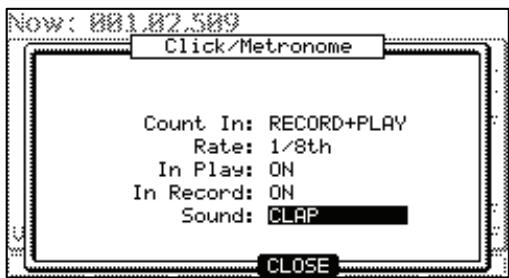
'Count In' field
You can set how soon the recording/playback should start after the [PLAY] or the [PLAY START] button is pressed; right after the key is pressed, or after a 1-bar count.
OFF
Recording/playback will start right after the key is pressed without a count.
REC ONLY
There will be a count only for recording/overdub. Playback will be started without a count.
REC+PLAY
There will be a count for both recording and playback.
'Rate' field
You can select the rhythm for the metronome sound. The metronome will be played with 1/4 note if you set '1/4', and 1/8 note if you set '1/8'.
'In play' field
You can select this if you want the metronome sound during playback. If you select YES, you will hear the metronome sound during playback.
'In Record' field
You can select this if you want the metronome sound during recording/overdub. If you select NO, you will not hear the metronome sound during the recording/overdub.
'Sound' field
Here, you can select what your metronome will sound like. Seven different sounds are available to use.
MPCCLICK
METRO TICK
CLAP
SHAKER
TAMBOURINE
SIDESTICK 1
SIDESTICK 2
Note Repeat
If you press a pad while holding the [NOTE REPEAT] button, the pad sound will be played repeatedly according to the value of the timing correct until you release the pad. You can also control its velocity by changing the strength used to press the pad. With the Note repeat feature, you can record a difficult phrase to record in real time, such as 16 beat hi hat, snare rolls, etc...
- Press and hold the [NOTE REPEAT] button during recording / playback.
- While holding the [NOTE REPEAT] button, press the pad to play repeatedly.
The pad's sound will be played repeatedly according to the value of the timing correct until you release the pad. You can also control its velocity by changing the strength with which you press the pad.
- While holding down the [NOTE REPEAT] button, the bottom of display is changed as shown on the right. You can change the Timing correct value directly with pressing the [F1] through [F6] button.
The selected Timing correct value is highlighted. You can select triplets of each timing correct value by pressing [F6].
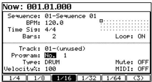
Note Repeat Hold
You can also latch 'Note Repeat' by holding down the [NOTE REPEAT] button and then pressing [SHIFT]. Pressing [NOTE REPEAT] again will unlatch the 'Note Repeat' feature.
Locate
The [GO TO] button is used to move to a specific position within a sequence. You can memorize up to five locate points.
Saving a Locate point
- In the MAIN page, press the [GO TO] button while the sequence is stopped.
The Locate window will be displayed as shown on the right. In the Go to' field, the now time in the MAIN page is displayed. You can enter the locate point you wish to save by using the numeric keys or the [DATA] wheel.
- Move the cursor to a one of the 'Locate' fields and press the [F2] (CAPTURE) button.
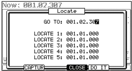
Locating to a saved Locate point
- In the MAIN page, press the [GO TO] button while the sequence is stopped.
The Locate window will be displayed. - Move the cursor to one of the 'locate' fields (Locate 1 - Locate 5) and press the [F5] (GO TO) button.
The Now Time instantly changes to the saved Locate point.
Tip: You can use the Locate feature in both the MAIN page and in the STEP/GRID mode.
Detailed Information on the Sequence Feature
Setting the Length of a Sequence
By default, a sequence is set to a 2-bar length, but you can set this length between 1 to 999 bars.
- In the MAIN page, select the 'Bars' field.
The 'Bar' field displays the current sequence length.
- Turn the [DATA] wheel, or press [WINDOW] button.
The CHANGE SEQUENCE LENGTH window will be displayed as shown.
- In the 'New Length' field, select the new number of bars.
If you set a larger number than the current value, empty bars will be added at the end of the sequence. If you set a smaller number, the bars in the end of the sequence will not be played.
- Press [F5] (DO IT) button
That applies the new setting and closes the window.
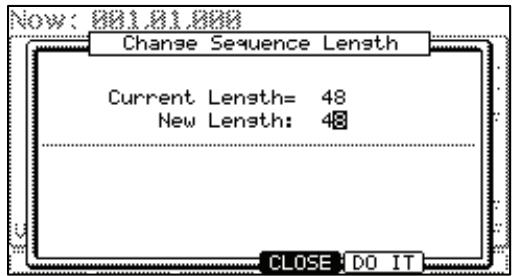
Tip: when you increase the length of the sequence, blank bars are added at the end of your sequence. If you decrease the length of a sequence, the last bars of the existing sequence are not played, but unlike previous MPC's, these bars are NOT truncated. This means that the length can be adjusted without losing the end bars of your sequence!
Tip: In SONG mode, you can also set a specific order for sequences playback. For more information, see 'SONG Mode' on page 55.
Setting the Time Signature of the Sequence
By default, the time of a sequence is set to the 4/4 time, but you can change the setting.
- In the MAIN page, select 'Time Sig' field.
The 'Time Sig' field displays the current value.
- Turn the [DATA] wheel or press the [WINDOW] button.
The TIME SIGNATURE window will be displayed.
The upper part of the screen indicates the number of bars. The currently selected time is displayed below it.
- Select the desired time signature, and set to this.
Select the bar to change the time with the right/left cursor keys and change the time with [DATA] wheel.
- Press [F5] (DO IT)
That changes the time signature of the bars and closes the window.
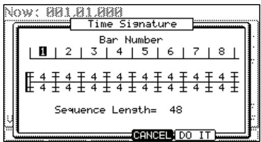
Note: if a bar becomes lengthened due to a time signature change, blank space is added to the end of the bar. If you decrease the length of a sequence, the last bars of the existing sequence are not played, but unlike previous MPC's, these bars are NOT truncated. This means that the length of a sequence can be adjusted without losing the end bars of your sequence!
Setting Tempo
You can set the beats per minute, or tempo, in the MAIN page by selecting the 'BPM' field.
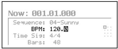
You can set the BPM for a sequence between 30.0 and 300.0 beats per minute. When the MPC5000 is set to follow an external source via MIDI clock, the 'BPM' field will display 'EXT', along with the tempo being received in brackets for external tempo.
You can change the BPM after you create the sequence, or change the BPM anywhere in a sequence by inserting the tempo change event in the STEP EDIT
mode. (See page 43 for more information.)
Tap Tempo
You can set the tempo using the [TAP TEMPO] button as well as in the 'Tempo' field.
Press the [TAP TEMPO] button along to the desired tempo, and the MPC5000 will calculate the tempo based on the timing that you tap. The sequence's tempo will automatically be set to the tapped value.
The MPC5000 takes the average of four taps of the pad, but you can adjust the number of taps used to calculate BPM in the 'Tap average' field in OTHER mode.
Changing Tempo of All Sequences At One Time
You can change the tempo of all sequences to the same tempo at one time. You can change the tempo of each sequence at any time after you create the sequence, but it is useful to change all the sequence at one time when you are creating one song with several sequences.
- In the MAIN page, select the 'BPM' field and press the [WINDOW] button.
The TEMPO CHANGE window will be displayed.
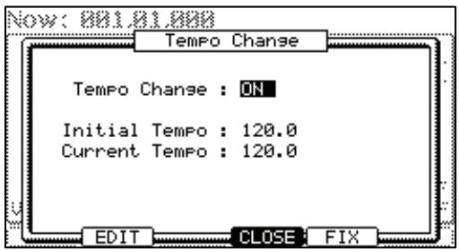
- Press [F5] (FIX) button.
The FIX TEMPO window will be displayed.
- In the 'Fix tempo' field, set the tempo.
- Press [F5 (DO IT) button.
It changes the tempo of all of the sequences to the value set in the 'Fix Tempo' field.

■ About Tempo Change
With the Step Recording feature in the STEP EDIT mode, you can insert tempo changes in a track, so that you can change the tempo within a sequence. When you use the Tempo Change feature, select the 'BPM' field in the MAIN mode and press the [WINDOW] button to open the TEMPO CHANGE window and set the 'Tempo change' field to ON.
When you turn the tempo change feature on, the 'BPM' field in the MAIN page will be displayed as below.
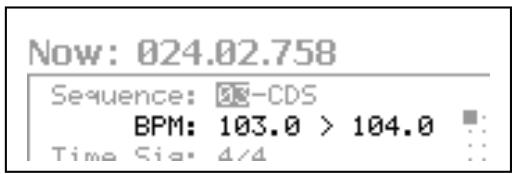
The tempo display on the left is the original tempo set for the sequence. On the right, the tempo you changed with the tempo change event will be displayed.
The sequence will actually be played at the tempo in the right.
To enter STEP EDIT mode, press [F2] (EDIT) while in the TEMPO CHANGE window.
Setting the Loop for a Sequence
By default, the MPC5000 has the sequence loop feature on. It is useful when you create a short sequence. With the sequence loop feature, you can overdub a new performance on top of a previous performance, allowing you to layer your tracks while playing back a sequence repeatedly.
However, when you are working on a long song, created as a single sequence, it may be better to loop only the part of the song that you are working on. Also, when you wish to play freely without worrying about the bars or times, it is
better to turn the loop feature off. In this section you will learn how to set the loop feature.
- In the MAIN page, select the 'Loop' field.
You can switch the sequence loop features on or off by turning the [DATA] wheel. In this field, you can only set whether the loop is on or off. You can set the start and end points of the loop in the LOOP window.
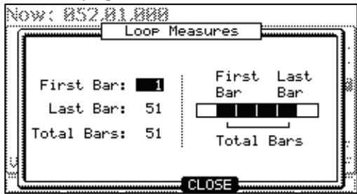
- Press the [WINDOW] button.
The Loop window will be displayed as shown on the right. The MPC5000 will repeat the part you set in the 'First Bar' and 'Last Bar' fields.
If you set END in the 'Last Bar' field, the last bar of the sequence is always the end of the loop. Even if you edit a sequence and change its length, the last bar of the sequence is still the end of the loop.
The 'Total Bars' field displays the length of the bars to loop. The 'Last Bar' field and the Total Bars' field work together. Changing the value in the 'Last Bar' field also changes the value in the Number 'Total Bars' field.
- Press [F4] (CLOSE) button.
This closes the window and goes back to MAIN page.
Extending the Sequence Length Automatically
Usually, the length of a sequence is set based on the value of the 'Bars' field in the MAIN page. However, when you are recording or overdubbing with the 'Loop' field set to OFF, the length of a sequence will be extended automatically. For example, when the 'Bars' field is set to 2, if you start recording with the 'loop' field set to OFF, the recording will continue after second bar until you press the [STOP] button. And the number of the bar when you actually pressed the [STOP] button will be set as the new length for the sequence. This is useful when you do not know how long the part you are composing will continue.
Tip: When you press the [PLAY START] button when the First bar is not 1, the MPC5000 will start the playback from the bar set in the 'First Bar' field instead of from the beginning of the sequence.
Changing the Default Settings
Some settings for a sequence (such as number of the bars, time, tempo, and loop) are automatically set to the default setting when you create a new sequence. You can change the default settings for your convenience.
- In the MAIN page, set the 'Loop', 'Time Sig' and 'Bars' fields as you like.
- Select the 'Sequence' field and press the [WINDOW] button.
The NAME SEQUENCE window will be displayed as shown.
- Press [F5] (USER) button.
The USER DEFAULT window will be displayed as shown.
- Press [F5] (DO IT) button.
The values currently set in the 'Loop', 'Time Sig' and 'Bars' fields in the MAIN page will be saved as default. The next time you create a new sequence these values will be applied to it.
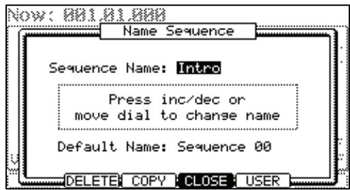
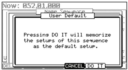
Changing the Sequence Name
- In the 'Sequence' field in the MAIN page, select a sequence that you wish to change the name of.
- Press the [WINDOW] button.
The NAME SEQUENCE windows will open.
- In the 'Sequence name' field, enter the new name.
For more information for setting the name, see the 'Setting the name' section on Page 18.
- Press [F4] (CLOSE) button.
This will close the window and goes back to MAIN page.
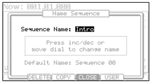
Changing the Default Name for a Sequence
Usually, when you create a new sequence, the name will be set to the default name as 'Sequence## (## will be the sequence number)' automatically. You can change the default name.
- In the MAIN page, select the 'Sequence' field.
- Press the [WINDOW] button.
The NAME SEQUENCE window will be displayed.
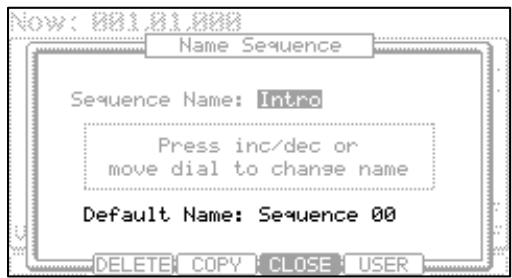
- In the 'Default name' field, enter the new name.
For more information for setting the name, see the 'Setting the name' section on Page 18.
- Press [F4] (CLOSE) button.
This closes the window and goes back to the MAIN page.
Copying a Sequence
You can copy a sequence to another sequence.
-
In the 'Sequence' field in MAIN mode, select a sequence to copy.
-
Press the [WINDOW] button.
The SEQUENCE WINDOW will be displayed.
- Press [F3] (COPY) button.
The COPY SEQUENCE window will be displayed as shown.
- In the 'Sequence' field (below), select the sequence number you wish to copy the selected sequence to.
If the selected sequence number is not blank, the name of the sequence will be displayed.
- Press [F5] (DO IT) button.
Copying the sequence will start. To cancel the operation, press [F4] (CANCEL).

■ Copying a Sequence Parameters ('Loop', 'Time Sig', 'Bars')
You can copy a sequence's parameters, including the 'Loop', 'Time Sig' and 'Bars' parameters to another sequence
- In the 'Sequence' field in MAIN mode, select a sequence whose parameters you wish to copy.
- Press the [WINDOW] button
The NAME SEQUENCE window will be displayed.
- Press [F3] (COPY) button.
The COPY SEQUENCE window will be displayed. - In the 'Sequence' field (below), select a sequence to copy to.
- Press [F3] (PARAMS) button
Copying the sequence's parameters will start. To cancel the operation, press [F4] (CANCEL).
- Deleting a Sequence
You can remove a sequence from the memory of the MPC5000.
- In the 'Sequence' field in MAIN mode, select a sequence to delete.
- Press the [WINDOW] button.
The NAME SEQUENCE window will be displayed.
- Press [F2] (DELETE) button.
The DELETE SEQUENCE window will be displayed.
- Press [F5] (DO IT) button.
This will delete the selected sequence and changes its name to 'unused'.
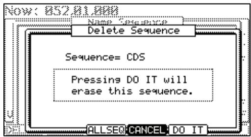
- Deleting All Sequences
You can delete all the sequence data in the memory at one time.
- In the MAIN mode, select the 'Sequence' field and press the [WINDOW] button.
The NAME SEQUENCE window will be displayed. - Press [F1] (DELETE) button.
The DELETE SEQUENCE window will be displayed. - Press [F3] (ALLSEQ) button.
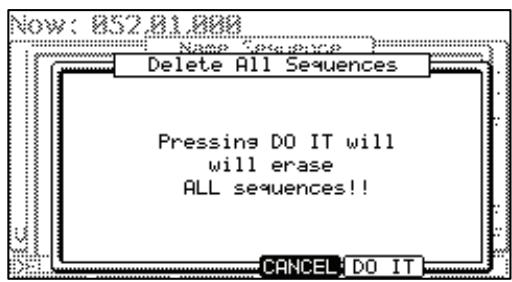
The DELETE ALL SEQUENCES window will be displayed.
- Press [F5] (DO IT) button.
That deletes all sequences. Sequence numbers will display 'unused' as a name until new data is recorded.
■ Handling the duration (the length of a note) at the loop boundary
When you are recording a sequence in the loop mode, you can specify how the MPC5000 should operate when it reaches the boundary of the loop (it reaches the end of the sequence and jumps back to the beginning) while you are holding a pad.
- Press the [MODE] button and then the [PAD 9] (OTHER) button.
That switches to the OTHER mode.
- Select the 'Truncate duration' field and select the option how to handle the duration between loops.
TO SEQ LENGTH
The MPC5000 records as played up to sequence length.
TO SEQ END
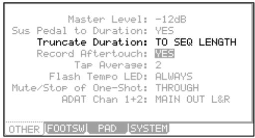
The MPC5000 cuts the note at the end of the sequence even if you hit the pad. You cannot record beyond the loop.
AS PLAYED
The MPC5000 records your performance as it is played.
Track Features
Setting the Track Type
You can set the track type in the 'Type' field in the MAIN page. There are two types of track: DRUM and MIDI. Below are the differences of each track type.
DRUM
Select this track type when you play the MPC5000's internal sampler by hitting pads. The DRUM track data will be managed per pad.
MIDI
Select this track type when you use the MPC5000 as a MIDI sequencer with external MIDI devices (MIDI keyboard etc...). The MIDI track data is managed per MIDI note event. For more information, see 'MIDI Sequencer Features' section on Page 35.
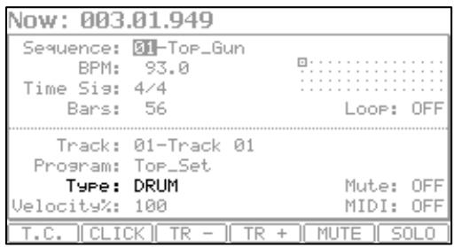
Selecting a Program
Playing Internal Programs
In the 'Program:' field, select the internal program loaded in the internal memory by turning the [DATA] wheel. You can play the selected program by hitting the pads. If you select 'OFF' or 'No.', the MPC5000 does not play the internal programs/samples.
Playing an External Sound Module
In the 'Program:' field, select 'OFF' or select a program number to play by choosing the 'Program Number' field (Displayed as 'No.') and select the desired program number. The MPC5000 will not play an internal program, but instead will 'trigger' an external sound module such as a synth via MIDI.
■ Sending MIDI Program Changes
When you select 'No.' in the 'Program:' field, the 'MIDI Program number' field will appear in the right side of the 'Program:' field. You can set the MIDI Program Number from 1 to 128. The selected MIDI Program Number will be transmitted from the selected MIDI OUT in 'MIDI' field when the sequence is selected or the [PLAY START] button is pressed.
While selecting the 'No.' in the 'Program:' field, pressing the [WINDOW] button will open the 'Program Change' window.
You can set a 'MIDI Bank Select' message to transmit together with a 'MIDI Program Change' message in this window. You can also set whether a 'MIDI Program Change' message recorded in the track is transmitted or not.
Bank Select: (ON/OFF)
Selects whether a 'Bank Select' message is transmitted or not.
MSB:/LSB:(0-127)
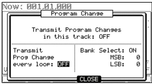
Sets the 'MSB' (Control Change # 0) and 'LSB' (Control Change #32) of a MIDI Bank Select message from 0 to 127.
Transmit Program Changes in This Track
Selects whether a 'MIDI Program Change' message recorded in the track is transmitted or not.
Transmit Prog Change every loop
Selects whether the sequence will send program changes whenever the sequence loops, or only on start.
Track Velocity
Track Velocity allows you to adjust the Velocity ratio on the selected Track while the sequence is playing.
Select the 'VELOCITY%:' field in the MAIN page and adjust the Velocity ratio by turning the [DATA] wheel from 1% to 200% .
Note: Changing the 'VELOCITY%' has no effect while recording sequence data; it will only affect the playback of a sequence. If the velocity is set to 127 (maximum), any setting over 100% will have no effect.
Track Mute
You can set the mute for each track independently. For example, let's assume you have recorded a Piano solo on track 1 and another piano solo on track 2. By setting either track to mute, you can compare these two piano solos and choose the better one. If you set the mute ON for a track, the MPC5000 won't play back that track.
Tip: using TRACK MUTE, you can set the track mute with a pad. For more information, see the 'Muting Sequence Tracks with Pads' section on Page 72.
Setting the MIDI Output Channel
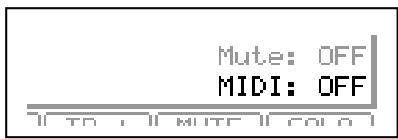
You can set the MIDI output channel for each track independently.
You need to set the output channel when you use the MPC5000 to play an external MIDI sound module. You do not have to set this when you are using the internal sampler.
The MPC5000 has four MIDI outputs. Channels 1A through 16A will be sent out via 16B through 16B will be sent out via MIDI OUT B, MIDI channels 1C through 16C will be sent out channels 1D through 16D will be sent out via MIDI OUT D.
Changing a Track Name
- In the 'Track' field in the MAIN page, select a track you wish to change the name on.
- Press the [WINDOW] button.
The TRACK NAME window will be displayed as shown.
- In the 'Track Name' field, enter the new name.
For more information for setting the name, see the 'Setting the name' section on Page 18. - Press [F4] (CLOSE) button.
This closes the window and goes back to the MAIN page.
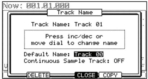
Changing the Default Name for a Track
Usually, when you create a new track, the name will be automatically set as default 'Track##' (# indicates track number). You can change the default track name.
- In the MAIN page, select the 'Track' field.
- Press the [WINDOW] button.
The TRACK NAME window will be displayed as shown.
- In the 'Default Name' field, enter the new name.
For more information about setting the name, see the 'Setting the name' section on Page 18.
- Press [F4] (CLOSE).
This closes the window and goes back to the MAIN page.
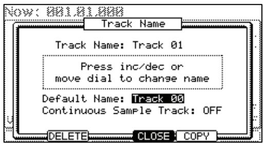
Copying a Track
You can copy a track to another track.
- In the 'Track' field of the MAIN mode, select a track to copy.
- Press the [WINDOW] button.
The TRACK NAME window will be displayed.
- Press [F5] (COPY) button.
The COPY TRACK window will be displayed as shown.
- In the 'Track' field (below), select a track to copy to.
- Press [F5] (DO IT) button.
Copying the sequence will start. To cancel the operation, press [F4] (CANCEL).
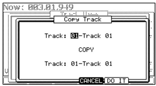
- Deleting a Track
You can remove a track from the memory of the MPC5000.
- In the 'Track' field in MAIN mode, select a track to delete.
- Press the [WINDOW] button.
The TRACK NAME window will be displayed.
- Press [F2] (DELETE).
The DELETE TRACK window will be displayed as shown. - Press [F5] (DO IT).
That deletes the selected track and changes its name to 'unused'.
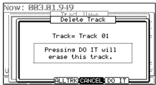
- Deleting all Tracks
You can delete all the track data in the memory at one time.
- In the MAIN mode, select the 'Track' field and press the [WINDOW] button.
The TRACK NAME window will be displayed.
- Press [F2] (DELETE) button.
The DELETE TRACK window will be displayed.
- Press [F3] (ALLTRK) button.
The DELETE ALL TRACKS window will be displayed as shown.
- Press [F5] (DO IT) button.
That deletes all the tracks and changes their names to 'unused'.
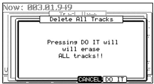
Continuous Sample Tracks
The MPC5000 plays samples assigned to pads when triggering the pad event. So that, if you have the sequence which has a long sample and start playing the sequence from a point which is past the actual pad event, the sample may not be played, because the pad event for the sample may be earlier than the sequence play start point.
A Continuous Sample Track allows samples assigned to the selected Pad in each track to be played from their current position, whenever [PLAY] or [PLAY START] is pressed. This way, if you are working with say, a four measure loop, pressing start at bar two will start the loop playing from its correct location at bar two immediately, without having to wait for a NOTE ON event.
Tip: New to the MPC5000 is the ability to have up to 64 continuous sample tracks, each assigned to a specific pad. This allows you to have multiple loops, assigned to multiple tracks, usable with the TRACK MUTE function. For more information on Track Mute, see page 72.
To enable 'Continuous Sample Track' on a selected track, do the following:
- In the MAIN mode, select the 'Track' field and press the [WINDOW] button.
The TRACK NAME window will be displayed.
- Select the 'Continuous Sample Track' field, and select 'ON'.
The 'Pad' field will be displayed below the 'Continuous Sample Track' field.
- Choose the pad you wish to have play continuously.
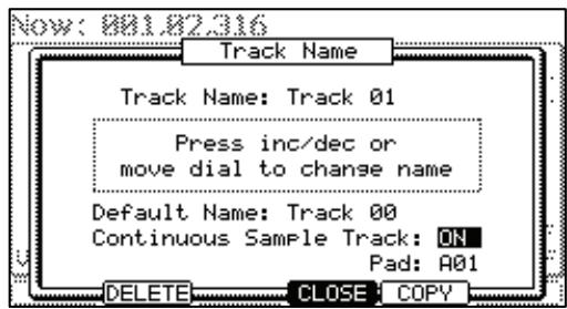
The selected pad will play as a continuous sample. Tracks set to Continuous will be displayed as a ^+ in the 'Track Status' field. For more on the 'Track Status' field, see page 20.
Selecting a Track with Function Keys

You can quickly switch tracks using [F3] (TR-) button and [F4] (TR+) buttons. With [F3] (TR-) and [F4] (TR+) buttons, you can easily select a track without moving a cursor to the 'Track' field.
Soloing a Track

When you are working on a sequence that has many tracks, it is useful to use the solo function to play back only the selected track. For example, when you are recording various instruments on several tracks, you can check the contents of each track with this feature.
- In the 'Track' field in the MAIN page, select a track you wish to play back.
- Press [F6] (SOLO) button and start recording/playback of the sequence.
The [F6] (SOLO) button will be highlighted and the MPC5000 plays back only the selected track and mutes all the other tracks.
- To cancel the solo, press [F6] (SOLO) button again.
The MPC5000 plays back all tracks.
MIDI Sequencer Features
When you are playing the internal sound module with the pads, you can start recording just by selecting the desired program in the 'Program' field in the MAIN page. However, the MPC5000 can be used as a MIDI sequencer. By connecting an external MIDI keyboard to it, you can record the data from the keyboard and control the external sound module.
About MIDI...
MIDI is a standard for transferring the performance data between electronic instruments regardless of the manufacturer. Devices are connected using a special cable called MIDI cable. For example, when you connect the keyboard's MIDI OUT to MIDI IN of the MIDI sound module, the performance data you made with your keyboard will be sent to the MIDI sound module, which plays the sound. MIDI can transfer only the performance data, not the actual sound. To transfer as much data as possible through one MIDI cable, there are MIDI channels. By using a MIDI channel, you can transfer different performance data to each channel separately. You can transfer the performance data to up to 16 channels. The MIDI channel is very important when you handle MIDI.
You must set the same MIDI channels for both the keyboard and the sound module even if you play the sound from the keyboard. For example, if the keyboard's output channel is set to 1, the sound module's input channel should also be 1. Some sound modules can receive several channels. In that case, you can assign a separate instrument (Piano, Bass, Strings etc...) to each separate channel.
About MIDI sequencers...
A MIDI sequencer is a device that can record and play back MIDI data. The MPC5000 can be used as a MIDI sequencer. When you connect an external MIDI keyboard to use the MPC5000 as a MIDI sequencer, connect the keyboard's MIDI OUT to MPC5000's MIDI IN, and the MPC5000's MIDI OUT to the external MIDI sound module's MIDI IN. Thus, you can record the keyboard performance to the MPC5000 and play sounds from the MIDI sound module. In this section, you will learn how to record the performance data from the external MIDI keyboard to the MPC5000 and play sounds from the external sound module.
- Connect the external MIDI devices as described in the 'Using the MPC5000 with External Devices' section on Page 167.
Connect the MIDI OUT of the keyboard to the MPC5000's MIDI IN, and the MPC5000's MIDI OUT to MIDI IN of the external sound module.
Note: You may still want to connect the MPC5000's stereo out to a mixer so that you can hear a metronome sound even when you use the MPC5000 as a MIDI sequencer.
- In the 'Type' field, select MIDI.
- In the 'Program' field, select OFF or No.
If you select it to the OFF or No., the MPC5000 does not play internal programs. If you select it to the No. and set MIDI Program number, MPC5000 transmit the MIDI Program number to the external sound module for selecting the sound in it when the sequence is selected.
- In the 'MIDI' field, select a MIDI channel.
Here, you set the MIDI channel to send the MIDI data on. Set the same channel as the one on the sound module.
Tip: By default the MPC5000's input MIDI channel is set to receive all MIDI channels, so you don't have to set the channel to the keyboard's MIDI channel.
- Play the keyboard to make sure the sound module works.
If you don't hear any sound, check the connection and make sure you have the correct settings for the keyboard and the sound module.
- Press the [PLAY START] button while holding the [REC] button.
The recording starts after 4 counts.
- Play the keyboard in time with the click sound.
By default, sequence is set to 2 bars. After recording for 2 bars, the MPC5000 will start playing back the recorded performance. If you make another performance with pads, you can add the performance to the currently recorded one. This is called 'overhub'.
- You can stop overdub by pressing the [STOP] button.
- Press the [PLAY] button to play the recorded performance.
- If you don't like the performance, you can start the new recording by pressing [REC] and [PLAY START].
This cancels the currently recorded performance data and starts the new recording.
- To add the recording to the already recorded data, press the [PLAY START] button while holding [OVERDUB] button.
This plays back the currently recorded performance and you can add the new performance by hitting pads.
Tip: If you select another sequence in the 'Sequence' field, you can record a new performance separately. By playing back those sequences, you can create one whole song.
Handling the Sustain Pedal
In this section, you will learn how to handle sustain pedal information when you are using an external MIDI keyboard with the MPC5000 as a sequencer.
Sustain pedal data is a MIDI event used to make the sound continue after a key on the keyboard is released. Usually a foot switch controls this data. The keyboard sends out Sustain pedal data as a separate event from a note event, so normally the sequencer recognizes this data as separate data. However, when you are overdubbing on a short sequence loop, it might be better to convert the sustain pedal's data to the recorded note's duration (the length of the note). For example, if you record the sustain pedal's data as it is, once you press the sustain pedal during the loop, sustain will be applied to all the data after that. If you convert the sustain pedal's data to note duration, the movement of the sustain pedal will not affect the other notes. Thus, the MPC5000 is set to convert the sustain pedal's data to note duration by default, but you can change the setting to record the data as sustain pedal data.
- Press the [MODE] button and then [PAD 9] (OTHER).
This switches the MPC5000 to OTHER mode.
- Select the 'Sus Pedal to Duration' field.
- Use the [DATA] wheel to select one of the following choices for how the MPC5000 will interpret the sustain pedal's MIDI data, depending on the desired behavior.
YES
The MPC5000 is set to convert the sustain pedal data to note duration.
NO
The MPC5000 records sustain pedal data as it is.
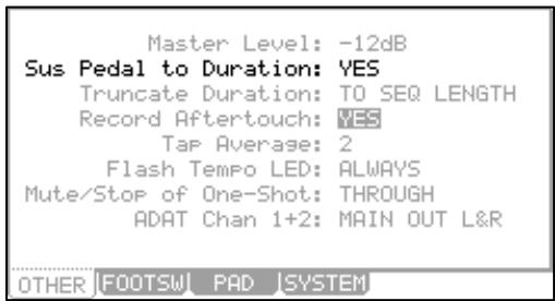
Recording Aftertouch
Aftertouch - also called Channel Pressure - is a specific controller event, which is generated when a pad is triggered, and then pressure is varied by pressing heavier or lighter. The pads on the MPC5000 are capable of sending aftertouch messages to both the MPC5000's internal synth, and to external devices via MIDI. Whether this aftertouch information is recorded or not can be selected by doing the following.
- Press the [MODE] button and then [PAD 9] (OTHER).
This switches the MPC5000 to OTHER mode. - Select the 'Record Aftertouch' field.
- Use the [DATA] wheel to select yes or no to decide if the MPC will record Aftertouch.
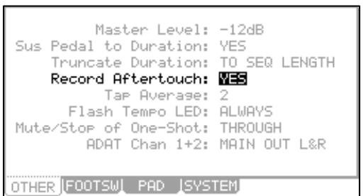
Chapter 4: Editing Sequences
There are two ways to edit sequences. Using SEQ EDIT mode, you can edit entire regions of events at one time with one sweeping action. Using STEP EDIT and GRID EDIT mode, you can edit your sequences in finer detail, manipulating every event individually. In this section, you will learn about the SEQ EDIT mode, where you can edit entire regions at one time. SEQ EDIT Mode can be accessed by pressing the [MODE] button and then [PAD 12].
Selecting a region for the editing
In the EVENTS page, there are six different editing options in the 'Edit' field: COPY, MOVE, TRANSPOSE, SHIFT TIME, VELOCITY, and DURATION. The procedure to select the editing region is the same for all six options. Let us begin with the selection of the editing region.
Tips: see page 23 for information on how to ERASE.
Setting the Range
Select the 'Range' field in the EVENTS page of the SEQ EDIT mode.
In the 'Range' field, you can set the start and end points of the editing region. For example, to edit the first bar of a 2-bar sequence, set this field to '001.01.000 - 002.01.000'. In this case, the event at the '002.01.000' point will not be edited.
If you set the end point '002.01.000', like in this picture, the area right before this point will be included in the area.
Setting the pad/ note number
- Select the 'Pads' field in the EVENTS page of the SEQ EDIT mode.
The display of the 'Pads' field depends on the type of the track that you have selected.
When DRUM track is selected:
By default, the field is set to ALL, which means the MPC5000 will edit all the pads. If you wish to edit only a specific pad, position the cursor in the 'Pads' field and hit the desired pad. The pad number will be displayed in the 'Notes' field. You can select several pads. If you hit a different pad by mistake, you can cancel the selection by hitting the pad again. To restart the pad selection, turn the [DATA] wheel to the left. The value in the 'Note' field will be reset to ALL so that you can select the pad that you want from the beginning.

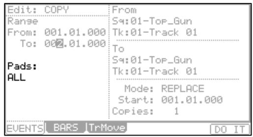
When MIDI track is selected:
The display changes to show the selected region by note number.
You will set the upper limit and the lower limit of the note in the field, The MPC5000 will edit only the events within the note numbers set in this field.
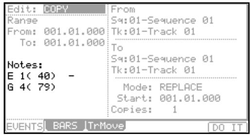
- Copying events (COPY)
You can copy events within the selected region to another place. The source data will remain in the original location.
- Select the 'Edit' field in the EVENT page of the SEQ EDIT mode, and select COPY.
The various fields necessary for the copying will be displayed.
- In the 'Range' field and the 'Pads/Notes' field, select the region and notes that you wish to copy.
- In the 'From sq' field and the 'Tk' field in the right, select the source sequence and track.
- In the 'To sq' and the 'Tk' field in the right, select the destination sequence and track.
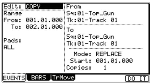
- In the 'Mode' field, specify how to copy the data to the destination.
REPLACE
The MPC5000 will overwrite the destination with the source data. The data that is already in the destination will be removed.
MERGE
The MPC5000 will merge the source data with the data that is already in the destination.
- In the 'Start' field, set the start point of destination time. The MPC5000 will start the copy to the time set here.
- In the 'Copies' field, set the number of times to copy.
To copy the same phrase repeatedly, enter the number of copies in the 'Copies' field. You can copy it repeatedly with one operation.
- Press the [F6] (DO IT) button.
The MPC5000 will start copying the data.
■ Moving events (MOVE)
You can move events within the selected region to another location. Unlike the copy function, this function will remove the source data from the original location.
- Select the 'Edit' field in the EVENT page of the SEQ EDIT mode, and select MOVE.
The various fields necessary for moving will be displayed. - In the 'Range' field and the 'Pads/Notes' field, select the region that you wish to move.
- In the 'From Sq' field and the 'Tk' field on the right, select the source sequence and track.
- In the 'to Sq' and the 'Tk' field on the right, select the destination sequences and tracks.
- In the 'Mode' field, specify how to move the data to the destination.
| Edit: MOVE | From |
| Range | Sq:01-Top_Gun |
| From: 001.01.000 | Tk:01-Track 01 |
| To: 002.01.000 | To |
| Pads: | Sq:01-Top_Gun |
| ALL | Tk:01-Track 01 |
| Mode: REPLACE | |
| Start: 001.01.000 | |
| EVENTS | BARS TrMove DO IT |
REPLACE
The MPC5000 will overwrite the destination with the source data. The data that is already in the destination will be removed.
MERGE
The MPC5000 will merge the source data with the data that is already in the destination.
- In the 'Start' field, set the start point of destination time.
The MPC5000 will start moving the event to the time selected here.
- Press the [F6] (DO IT) button.
The MPC5000 will start moving the event.
Transpose
You can transpose (change the key of) the note events. This operation changes the selected track, whether it's a DRUM track or a MIDI track.
- Select the 'Edit' field in the EVENT page of the SEQ EDIT mode, and select TRANSPOSE.
The various fields necessary for the transpose will be displayed. - In the 'Range' field and the 'Pads/Notes' field, select the region that you wish to edit.
- In the 'Edit Sq' field and the 'Tk' field on the right, select the sequence and track that you wish to edit.
When the MIDI track is selected, the 'Amount' field is displayed. Set the amount of the transpose in the 'Amount' field. The unit of the amount is semi tone. When the DRUM track is selected, the 'Pad' field is displayed. You can change the selected pa you wish to change in the 'Pad/Notes' field and then select the destination Pad in the
In the Edit 'Sq' field and 'Tk' field, you can select ALL by turning the [DATA] wheel.
When you select ALL, the Transpose is performed on all sequence or all tracks.
| Edit: TRANSPose Edit |
| Range: Sq:01-Top_Gun |
| From: Tk:01-Track 01 |
| To: |
| Pads: |
| A10 |
| Pad: A01 |
| EVENTS|BARS|TrMove DO IT |
/hen you select ALL, the Transpose is performed only in the MIDI tracks, not in DRUM tracks.
- Press the [F6] (DO IT) button.
The MPC5000 will start processing your changes.
Changing the timing of an event (SHIFT TIMING)
You can shift the timing of the note event.
- Select the 'Edit' field in the EVENT page of the SEQ EDIT mode, and select SHIFT TIMING.
The various fields necessary for the Shift Timing will be displayed.
- In the 'Range' field and the 'Pads/Notes' field, select the region that you wish to edit.
- In the 'Edit Sq' field and the 'Tk' field on right, select the sequence and track that you wish to edit.
In the Edit 'Sq' field and the 'Tk' field, you can select ALL by turning the [DATA] wheel. When you select ALL, the MPC5000 will shift the timing of all the sequence and tracks.
- In the 'Amount' field, set the amount of Shift timing.
This is a value in clock ticks the selected region will be moved.
- Select the direction of Shift Timing.
EARLIER: Shifts forward
LATER: Shifts back
- Press the F6 (DO IT) button
The MPC5000 will start processing your changes.
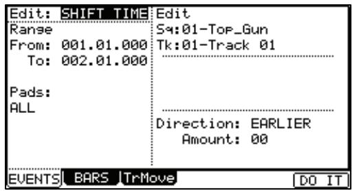
Changing the Velocity of an event (Velocity)
You can change the velocity of any note event.
- Select the 'Edit' field in the EVENT page of the SEQ EDIT mode, and select Velocity.
The various fields necessary for changing the velocity will be displayed.
- In the 'Range' field and the 'Pads/Notes' field, select the region that you wish to edit.
- In the Edit 'Sq' field and the 'Tk' field on the right select the sequence and track that you wish to edit.
In the Edit 'Sq' field and the 'Tk' field, you can select ALL by turning the [DATA] wheel. When you select ALL, the MPC5000 will change the velocity of the sequence and all its tracks.
- In the 'Mode' field, choose the method of velocity change.
ADD VALUE
Adds the value selected in the 'Value:' field to the note.
SUB VALUE
Subtracts the value selected in the 'Value:' field from the note.
MULTI VAL%
Multiplies the Velocity (percent) by the value selected in the 'Value:' field.
SET TO VALUE
Sets the note to the Velocity selected in the 'Value:' field.
- In the 'Value' field, set the value to be adjusted. You can set the Value between 0 and 127. When you select 'MULTI VAL%' in the 'Mode' field, you can set the Value between 0 and 200.
- Press the F6 (DO IT) button
The MPC5000 will start processing your changes.
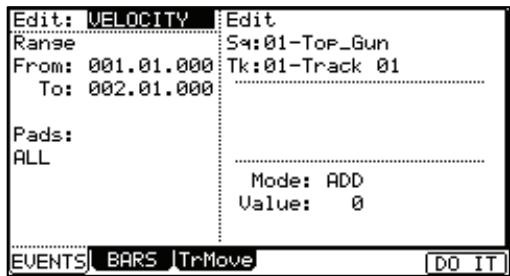
Changing the duration of an event (DURATION)
You can change the Duration of any note event.
- Select the 'Edit' field in the EVENT page of the SEQ EDIT mode, and select DURATION.
The various fields necessary for changing the duration will be displayed.
- In the 'Range' field and the 'Pad/Notes' field, select the region that you wish to edit.
- In the Edit 'Sq' field and the 'Tk' field on the right select the sequence and track that you wish to edit.
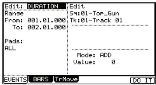
In the Edit 'Sq' field and the 'Tk' field, you can select ALL by turning the [DATA] wheel. When you select ALL, the MPC5000 will change the Duration of the events in the track.
- In the 'Mode' field, select how you want to change the Duration.
ADD VALUE
Adds the value in MIDI pulses selected in the 'Value:' field to the note.
SUB VALUE
Subtracts the value in MIDI pulses selected in the 'Value:' field from the note.
MULTI VAL%
Multiplies the Duration (percent) by the value in MIDI pulses selected in the 'Value:' field.
SET TO VALUE
Sets the note to the duration in MIDI pulses selected in the 'Value:' field.
- Press the F6 (DO IT) button
The MPC5000 will start processing your changes.
Selecting the editing region by bar
You can edit the sequence by bar. This is done in the BARS page in the SEQ EDIT mode, which can be accessed by pressing the [MODE] button and then the [PAD 12].
Copying bars (COPY)
You can copy bars within the selected region to another place. The length of the destination sequence will be extended to add the copied bars.
- Select the 'Edit' field in the BARS page of the SEQ EDIT mode, and select COPY.
The various fields necessary for copying will be displayed. - In the 'From Sequence' field, select the source sequence.
- In the 'To Sequence' field, select the destination sequence.
- In the 'First bar' field, select the first bar of the source sequence.
- In the 'Last bar' field, select the last bar of the source sequence.
- In the 'After bar' field, select the destination.
The selected bars will be copied to the end of the bar set here.
- In the 'Copies' field, select the number of times to copy the data.
To copy the same phrase repeatedly, enter the number of copies in the Copies field. You can copy it repeatedly with one operation.
- Press the [F6] (DO IT) button.
The MPC5000 will start copying the bars.
Inserting a bar (INSERT)
To insert empty bars in the sequence, proceed as follows:
- Select the 'Edit' field in the BARS page of the SEQ EDIT mode, and select INSERT.
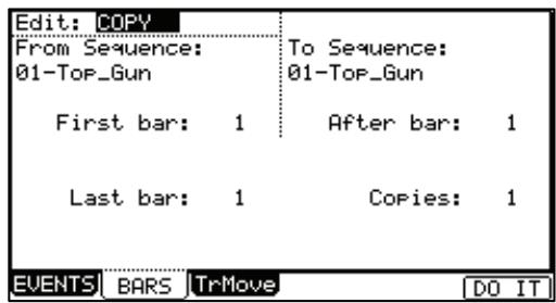
The various fields necessary for inserting bars will be displayed.
- In the 'Sequence' field, select the sequence that you wish to insert the bars.
- In the 'After bar' field, select the location to insert the bars in.
The selected bars will be inserted at the end of the bar set here.
- In the 'Number of bars' field, set the number of bars to insert.
- In the 'Time signature' field, select the time signature of the bars to insert.
- Press the [F6] (DO IT) button.
The number of empty bars selected will be inserted at the selected location.
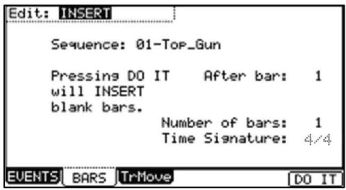
- Deleting a bar (DELETE)
To delete the selected bar(s) in the sequence, proceed as follows:
- Select the 'Edit' field in the BARS page of the SEQ EDIT mode, and select DELETE
The fields necessary for deleting the bars will be displayed.
- In the 'Sequence' field, select the bars to delete.
- In the 'First bar' field, specify the first bar to delete.
- In the 'Last bar' field, specify the last bar to delete.
- Press the [F6] (DO IT) button.
The selected bar(s) will be deleted.
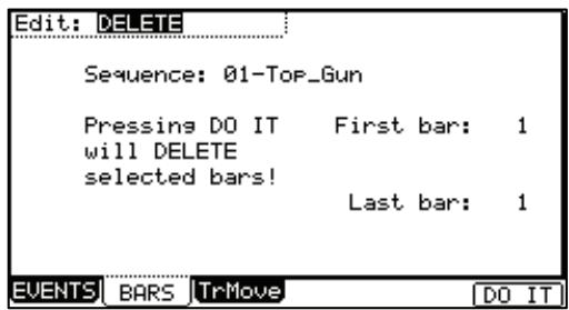
Changing the order of tracks (TRACK MOVE)
When you are creating a song by combining several short sequences, normally you would use the SONG feature to play back sequence in the specified order. The MPC5000 can convert the song data with short sequences to one long sequence. To do this, you need to arrange the order of the tracks in each sequence. In this section, you will learn how to use the track move function to change the order of the tracks in a sequence.
You can move tracks in the TrMOVE (Track move) page of the SEQ EDIT mode, which can be accessed by pressing the [MODE] button and then the [PAD 12].
- In the SEQ EDIT mode, press the [F3] (TrMOVE) button. The TrMOVE (Track move) page will be displayed.
- In the 'Sequence' field, select the track that you wish to change the order.
- In the 'Reference Sequence' field, select the sequence to be used as the reference when changing the order.
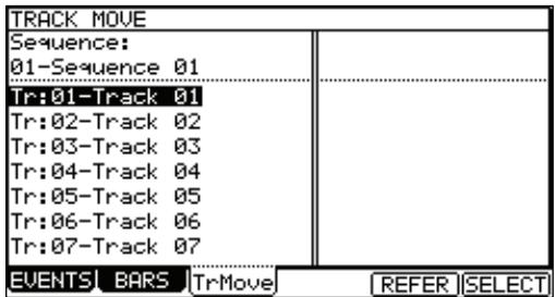
For example, if you want other tracks to follow the order in sequence 01, you should select sequence 01 in the 'Reference Sequence' field.
- Using the down cursor key, move the cursor to the track list.
- You can scroll through the list by turning the [DATA] wheel. Select the track that you wish to move.
- Press the [F6] (SELECT) button.
This selects the track.
To select a track again, press the [F5] (CANCEL) button.
- Select the destination by turning the [DATA] wheel.
The list will scroll with the track selected in steps 5 and 6 fixed.
Refer to the list on the left to select the destination position.
- Press the [F6] (MOVE) button.
The track will move to the selected location and the order will be changed.
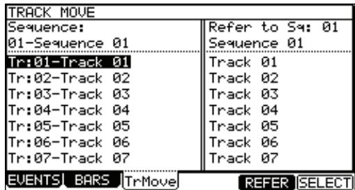
Chapter 5: STEP EDIT Mode
Unlike SEQ EDIT Mode, STEP EDIT allows you a way to easily edit individual events one at a time. In this section, you will learn about the STEP EDIT mode, where you can edit each event in detail. STEP EDIT mode is accessed by pressing [MODE] + [PAD13].
A Note about Playing Events
You can audition events while in STEP EDIT Mode by selecting the event and pressing the [F6] (PLAY) button.
About Step Edit
Each track has the performance data you made with pads or MIDI note information from an external MIDI keyboard. The Step Edit function allows you to edit each event separately, including individual note velocity, pitch, and duration, as well as MIDI controller data, program changes, and other types of events. There are also events specific to the MPC5000, such as Q-LINK controllers, pad tuning and tempo.
'Now' field
The 'Now' field is displayed in the upper left corner on the screen. The 'Now' field always displays the current position of a sequence. This is the same as the 'Now' field on the MAIN page.
Event List
The event list is displayed below the 'Now' field and the 'View' field. This is where the events of a track are listed, their parameters, and at what time they each occur. This is where the editing of specific events is performed.
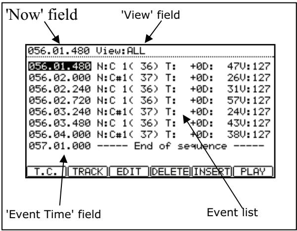
Note: The sequencer of the MPC5000 divides the quarter note into 960 parts. These divisions are called ticks.
View' field
The 'View' field allows you to simplify the event list by setting what is to be displayed. The event list will only display the events specified in this field. This is useful for customizing what's displayed, and filtering out unneeded events.
Event Time field
The 'Event time' field is displayed on the left of the event list. It displays the positions of the events within the track.
Event
The 'Event' field is displayed to the right of the 'Event time' field. The display will differ depending on the type of event. You can change the value by moving the cursor to each parameter and adjusting the values with the [DATA] wheel. Numerical values can also be entered using the [NUMERIC KEYPAD].
Basic operation
Event List
When the cursor is in the 'Now' field or 'View' field, pressing the down [cursor] will move the cursor to the event list. This is where the events in the track are listed. You can select the events with up/down [cursor] buttons and the field with the right/left [CURSOR] buttons. You can change the value in the field by turning the [DATA] wheel.
When the cursor is in the 'Event time' field, pressing the left [CURSOR] will move the cursor to the 'Now' field. In the event list, you can select several events at one time by pressing the down [CURSOR] while holding the [SHIFT] button.
[F1] (T.C.)
This velocity works the same as the [F1] (T.C.) button in the MAIN page. For more information, see the 'Timing correct' section on page 24.
The Timing Correct setting will determine the time division for Step Recording. See page 47 for more on Step Recording.
[F2] (TRACK)
Pressing and holding this button displays the window to change tracks. Using this button, you can select a track without switching back to the MAIN page.
[F6](PLAY)
Pressing this button will audition the selected event.
Events
Pad Event
This is the event that is recorded when you hit the pads in the DRUM track.
'P (pad)' field
You can set the pad number in this field.
'Note Variation' field
In the above picture, the area that displays 'T' is the 'Note Variation' field. You can select the type of note variation data to record with the Q-LINK sliders.
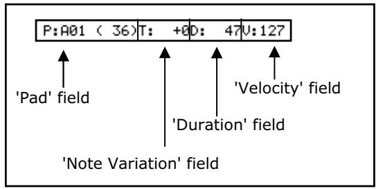
T Tune (pitch)
F Filter
L Layer
A Attack time
D Decay time
Tip: Note variation data, which is used for the Q-LINK sliders or [16 LEVELS] function, is the information used to control the sound of a pad, and is saved in the track along with the pad event. With the note variation data, you can switch the sounds of the pad even when you are playing back the same pad.
'Note variation value' field
In this field, displayed to the right of the 'Note Variation' field, you can set the note variation value.
'D(duration)' field
Here, you can set the duration of notes and pad events. This parameter determines how long the pad or MIDI note is held. The value is displayed in MIDI Ticks.
'V (velocity)' field
Here, you can set the velocity of a pad. Velocity is a measure of how hard the pad was hit. The velocity is shown in 127 steps, with 127 the maximum. This can be used to play sounds softer, louder, or control the filter cutoff etc. For more information on velocity, see 'Note Number, Velocity, and Length' on page 14.
■ Tempo Change Event
Tempo change event is used to change the tempo within the sequence.
The tempo change event is different from other events. It does not belong to a specific track. By selecting TEMPO in the 'View' field, you can display the tempo change event information separately, regardless of the selected track. Even when you have selected ALL EVENTS in the 'View' field, the tempo change event will not be displayed in the event list.

% field
You can set the amount of the tempo change.
Initial / Current Tempo
The 'initial tempo' field displays the original tempo set in the 'tempo' field of the sequence, the 'Current tempo' field displays the new tempo changed by the setting in the % field.
■ Effect Select Event
This event is used to switch the effect sets within the sequence.
EFFECT SELECT:01
Real Time Event
This is the real time event assigned on Q-LINK sliders and knobs.
'Pad' Field
You can set the pad number in this field.
REAL TIME:A01(35):CUT1
Pad field Event field
'Event' Field
You can set the event variation in this field. The events described here are specific events to the MPC5000.
TUNE
The pitch of the sample
CUTOFF
The cutoff frequency of the Filters
LEVEL
The volume level of the sample
RESO
The resonance value of the Filter
PAN
The panning position
Note: Both the LEVEL and PAN events share the Q-LINK value. For more information, see 'Q-LINK Controllers' on page 163.
Below are the MIDI events that you use when using the MPC5000 as a MIDI sequencer.
Note: How a MIDI event affects an external sound module depends on the specification of the sound module. For more information about the effect of each MIDI event, see the operation manual of your sound module.
Note Event
This is a MIDI note event.
N:36(C1) D:14U:127
'N (Note number)' field
You can set the note number in this field. A note number indicates the location on a keyboard as a numbers, with the middle C of the piano as note number 60.
'D (duration)' field
You can specify how long a note is held (length of a note). In the MIDI standard, pressing a key is called 'Note on', releasing a key is called 'Note off'. In this field, you will set the time from Note on to Note off.
'V (velocity)' field
You can set the velocity of the note event. In the MIDI standard, the speed used to trigger a note is called velocity. The velocity is shown in 127 steps, with 127 the maximum.
Pitch Bend Event
PITCH BEND
You can set the pitch bend. Normally this event is used to control the pitch in real time.
Control Change Event
CC: 1-BANK SELECT MSB : 0
The control change, which is used for various applications, is the most
versatile event in the MIDI standard. The control change event consists of a control number, which determines the type of the control change, and the control change value.
'CC' field
You can select the type of the control change in this field, and the control change value in the field on the right.
■ Program Change Event
PROGRAM CHANGE 1
You can set the program change. This event is normally used to switch the sound
of an external sound module. If program numbers are assigned to programs in the internal sampler section, you can switch the programs that are assigned to the track within the sequence.
■ Channel Pressure Event
You can set the channel pressure. Normally, a Channel pressure event is used for aftertouch. This feature allows you to control the sound depending on the pressure used to press the keyboard.
CHANNEL PRESSURE
Poly Pressure Event
POLY PRESSURE:60(C3) 0
The Poly pressure event is used for aftertouch much like the channel pressure event, however the Poly pressure event can be set to different values for each individual note.
Exclusive Data Event
EXCLUSIVE 120Byte
Exclusive data event is used to set the sound module, or to give a more detailed setting to the sound module, which cannot be done using control changes. The MPC5000 can record and play back System Exclusive Data. The type of exclusive data you can receive and their functions are determined by each manufacturer.
An exclusive data event displays only the size of the event data. This data cannot be edited directly.
Copying / Pasting an Event
To copy the selected event and paste it to another location, proceed as follows.
- In the event list, select the event that you wish to copy.
You can select several events by pressing the down cursor button while holding the [SHIFT] button.
- Press [F3] (EDIT) and [F4] (COPY) at the same time.
When you press [F3] (EDIT), the display of the [F4] and [F5] buttons will change to (COPY) and (PASTE) respectively until you release the button.
-
In the 'Now' field, select the time position that you wish to paste the event to.
-
Press [F3] (EDIT) and [F5] (PASTE) button at the same time.
The selected event will be pasted.
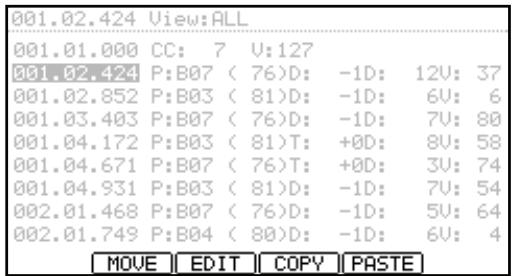
Moving an Event
To move the selected event to another location, proceed as follows. This differs from the Copy/Paste command in that the selected event is deleted from the original location after the Move function.
- In the Event list, select the Event that you wish to move. You can select several Events by pressing the down cursor button while holding the [SHIFT] button.
- Press [F3] (EDIT) and [F2] (MOVE) at the same time.
When you press [F3] (EDIT), the display of the [F2], [F4], and [F5] buttons will change to (MOVE), (COPY), and (PASTE) respectively until you release the button.
- Move Event window will be displayed.
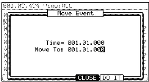
Time=
The selected event time (the start point) is displayed. You can not change this value.
Move to
You set the time where you wish to move the selected event.
- Press [F5] (DO IT).
The selected event will be moved.
Deleting an event
To delete the selected Event, proceed as follows.
- In the Event list, select the Event that you wish to delete.
You can select several Events by pressing the down cursor button while holding the [SHIFT] button.
- Press the [F4] (DELETE) button.
The selected Event will be deleted.
Note: You can also delete the Event by pressing the [Erase] button in Step Edit mode.
After copying / deleting an Event, you can revert back the previous status by pressing the [UNDO] button.
Step Recording
In the STEP EDIT mode, when you hit a pad, or when the MPC5000 receives MIDI data from an external device, you can record the event in the current time position (the time displayed in the 'Now' field). Move the event to the desired time position by moving through the event list with the up/ down cursor buttons, or by setting the time position in the 'Now' field, and you can add events to the desired time position one by one. This method, recording each event individually when MPC5000 is in the stop mode, is called step recording.
- In the STEP EDIT mode, Press [REC] or [OVERDUB].
The LED of [OVERDUB] will be lit, which indicates that you can now enter events by hitting a pad. - Move through the list with the up/down cursor buttons, or select the 'Now' field, to select the time position to insert event.
- Hit a pad.
The event of the pad will be recorded.
- Press [STOP].
The LED of [OVERDUB] will be turned off and you can finish the step recording.
Detailed setting for step recording
Pressing [WINDOW] in the STEP EDIT mode brings up the Step Edit Options window, where you can make various settings for the step recording.
'Auto step increment' field
If you select YES, the MPC5000 will automatically update the sequence according to the setting of the timing correct when it receives a pad event or a note event. Use the [
Duration of recorded notes' field
You can determine how the length that a pad (MIDI keyboard) is pressed affects the event to record during step recording.
AS PLAYED
The length that a pad (MIDI keyboard) is pressed will be applied to the event.
When you hit a pad or play a MIDI keyboard, the metronome sound will start automatically. Refer to the metronome sound to set the length to press a button. When you release a pad (MIDI keyboard), the length that a key was pressed will be entered in the 'D (duration)' field.
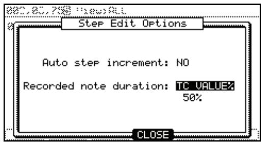
TC VALUE%
When this is selected, the duration of events recorded in 'Step Record' mode will be automatically set to a percentage of the Timing Correct Setting. For example, if Timing Correct is set to 1/8th notes, a TC VALUE% of 50% will set the duration of each event to one-half the length of the Timing Correct setting. In this case, the length of each recorded event will be 16th notes.
Setting a TC VALUE% of 100% will insert events equal to the Timing Correct length.
Inserting an event
During the step recording, you can enter events using the insert function as well as using pads and MIDI keyboard.
- Move to the time position that you wish to insert the event, and press [F5] (INSERT).
The Insert Event window will be displayed.
- In the 'Type' field, select the event to insert, and press [F5] (DO IT).
The selected event will be inserted.
Hint: After completing the Step recording, you can go back the previous status by pressing the [UNDO] button.
Chapter 6: GRID EDIT Mode
The MPC5000 has the GRID EDIT mode for editing or entering Pad events and Note events in a sequence. In GRID EDIT mode, you can enter and edit Events in the Graphic Matrix Editor.
About Grid Edit
Each track in the MPC5000 contains performance data entered with the pads, or with an external MIDI keyboard. In GRID EDIT mode, you can enter or edit (Copy, Delete, Move, etc.) the Pad Event, MIDI notes, or controller data on a graphical matrix. Pressing the [MODE] button and then pressing [PAD 14] (GRID EDIT) will allow you to enter GRID EDIT mode. GRID EDIT mode's view will change, depending on what type of track is being viewed.
DRUM View
When the current track 'TYPE' is set to 'DRUM' on the main page (See page 19), the track will be displayed in a 'Step-Sequencer' style as above. This allows for easy editing of 'DRUM' type tracks in a matrix display.
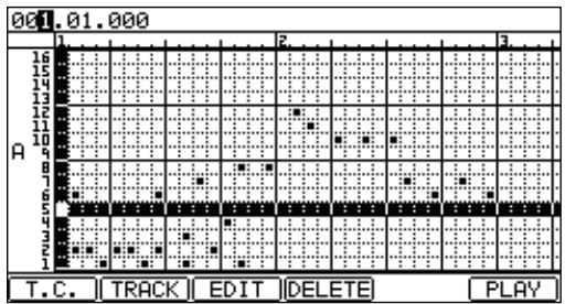
MIDI View
When the current track 'TYPE' is set to 'MIDI' on the main page (See page 19), the track will be displayed in a 'Piano Roll' style as above. This allows for easy editing of 'MIDI' type tracks in a matrix display. This view is useful to also see the duration of each note played.
Which octave is being viewed can be selected by changing the field on the right of the screen.
Both of these views share the following parameters:
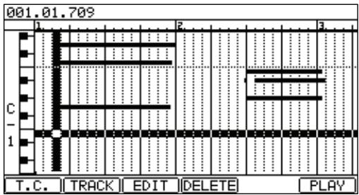
Now
The 'Now' field is displayed in the upper left corner on the screen. The 'Now' field always displays the current position of
a sequence. This is the same as the 'Now' field on the MAIN page.
Time ruler
This indicates the time axis of the track. The number in the ruler shows the bar number.
Vertical marker
This indicates the current location. You can use it to select the editing region on the time ruler.
Horizontal marker
This selects the pad number or note that you wish to edit.
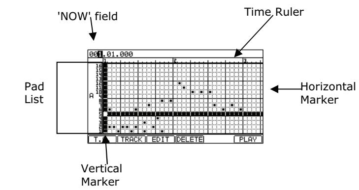
Event Range' field
This displays the range of events being viewed. This will change to show pad numbers, note octaves, or a 0-127 scale depending on the selected view.
Event Area
This area graphically displays the note events recorded in the track. The unit of the grid for editing is changed by the Timing Correct parameter.
Basic operation
Operation in the Event area
When the cursor is in the 'Now' field, pressing the down cursor button moves the cursor to the Event area. The cursor in the Event area is at the grid where the vertical and horizontal markers intersect. Your editing operations will be affected in the selected grid.
You can move the cursor in the Event area by the cursor buttons. You can also move the cursor to horizontal directions by turning the [DATA] wheel.
If the Event area is not shown in the grid, the time ruler will move and the next event area will be shown by turning the [DATA] wheel.
When the horizontal marker is the upper side of the Event area, pressing the up cursor button will move the cursor to the 'Now' field.
■ Relationship of Grid Value to Timing Correct.
The unit of the grid in the Event area is changed by the Note value in the Timing Correct window which is shown by pressing the [F1] (T.C.) button.
When you set the Note value to 1/16, one unit of the grid is 1/16 notes. When you set the Note value to 1/8, one unit of the grid is set to 1/8 notes.
Example: First, the Note value has been set to 1/32 and the Pad Events are recorded as in the drawing below
If you change the Note value to 1/16, the even area will be changed as follows.
In this case, every single event is displayed in the first four grids but each grid actually has two Pad Events.
When you edit (such as copy/paste/delete/move) the grid, all the events in the grid are edited.
Note: If you only wish to change how the units are displayed in the grid, press the [F4] (CLOSE) button after changing the Note Value in Timing Correct window. If you press the [F5] (FIX), the MPC50000 will begin processing the Timing Correct change.
Selecting an event
When you select the Pad Event, move the cursor to the grid of the Pad Event by pressing the cursor buttons.
For example, if you wish to select the PAD A03 event at 001.04.00 in the display, press the right cursor button several times (or turn the [DATA] wheel) and move the cursor to the position of 001.04.00. The vertical marker moves and the display in the 'Now' field becomes to '001.04.000'. Next, move the cursor to the PAD A03 row by pressing the down cursor button. The display will looks like this.
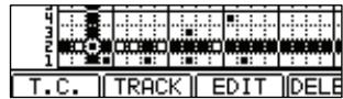
The event will now be displayed as a white '■' symbol within the Now Time marker. Now the event in the grid is selected.
In the Event area, you can select several pads and regions by pressing the [SHIFT] button and moving the cursor button.
When the cursor is in the event area, pressing the [WINDOW] button will display the 'Events' window. The selected Pad Events are displayed in this window. If you select several grids, all the Pad Events in the grid will be displayed.
'Tick' field (left side)
This shows the tick value of the Event. It cannot be edited.
'P' (pad) or 'N' (note) field
You can select the Pad Number or Note in this field
In the above picture, the area that displays 'T' is the 'Note Variation'
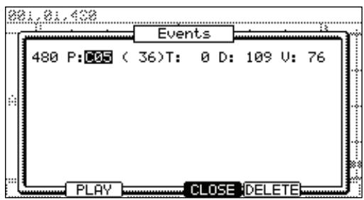
field. You can select the type of note variation.
T Tune (pitch)
F Filter
L Layer
A Attack time
D Decay time
Tip: Note variation data, which is used for the Q-LINK sliders or [16 LEVELS] function, is the information used to control the sound of a pad, and is saved in the track along with the pad event. With the note variation data, you can switch the sounds of the pad even when you are playing back the same pad.
'Note Variation Value' field
In this field, displayed to the right of the 'Note Variation' field, you can select the Note Variation Value.
'D(duration)' field
You can specify how long a note is held (length of a note). In the MIDI standard, pressing a key is called 'Note on', releasing a key is called 'Note off'. In this field, you will set the time from Note on to Note off.
'V (velocity)' field
You can set the velocity of the note event. In the MIDI standard, the speed used to trigger a note is called velocity. The velocity is shown in 127 steps, with 127 the maximum.
Editing in GRID EDIT mode
You can edit events in GRID EDIT mode as well as in STEP EDIT mode.
[F1] (T.C.) Button
This button works the same as the [F1] (T.C.) button on the MAIN page. It allows you to select the Timing Correction. For more information, see the section entitled 'Timing correct' on page 24.
[F2] (TRACK) Button
Holding in this button displays a window which will allow you to choose a different track to edit.
When you have made your selection with the [DATA] wheel, simply let go of [F2] (TRACK). This way, you can select a track without having to switch back to the MAIN page.
![AKAI MPC5000 - [F2] (TRACK) Button - 1](/content/2025/01/152537/images/eba0b231aac5520b8ac270400b4a90495f5e3a4cef857d47ad7e1a9138f89af4.jpg)
[F3](EDIT) Button
Pressing this button will display (MOVE), (EDIT), (COPY), and (PASTE) on [F2] - [F5] buttons as shown here.
The function of these will be discussed in the next section.
 Button - 1](/content/2025/01/152537/images/e64a8b085e84026a36f45c75da9ebfeca2cfd3105714e7ae8d28f99cd2b54fd3.jpg)
[F4] (DELETE) Button
You can delete a selected Event by pressing this button.
[F6](PLAY)Button
This button allows you to play the selected event as it was recorded. This is useful for auditioning specific notes in a complicated recording.
Copying and Pasting an Event
To copy the selected Event and paste it to another location, proceed as follows.
- In the Event list, select the grid and the range that you wish to copy.
You can select several Pads by pressing the up/down [CURSOR] buttons while holding in [SHIFT]. You can then select several Grids by pressing the right/left [CURSORS] or turning the [DATA] wheel while holding [SHIFT].
- Hold down [F3] (EDIT) and then press [F4] (COPY).
When you press [F3] (EDIT), the display of the [F4] and the [F5] buttons will change to (COPY) and (PASTE) respectively until you release the button.
- Move the cursor to the Grid or select the Time Position in the 'Now' field you wish to paste the event to.
- Press in and hold [F3] (EDIT) and then press [F5] (PASTE).
The selected Event will be pasted.
Moving an event
You can move an Event to another position. After moving the Event, it does not remain at the original position, which is different from copying/pasting an Event.
- In the Event list, select the Grid and the Range that you wish to move.
You can select several Pads by pressing the up/down [CURSOR] buttons while holding in [SHIFT]. You can then select several Grids by pressing the right/left [CURSORS] or turning the [DATA] wheel while holding [SHIFT].
- Press in and hold [F3] (EDIT) and then press [F2] (MOVE).
When you press [F3] (EDIT), the display of [F2] will change to (MOVE) until you release the button.
- The Move Events window will be displayed.
Time =: The selected Event time (the start point) is displayed. You cannot change this value.
Move to: You select the time that you wish to move the selected Events to.
- Press [F5] (DO IT).
The selected event will be moved.
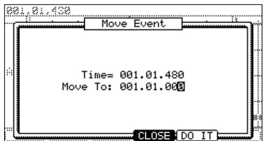
Deleting an event
To delete a selected Event, proceed as follows.
- In the Event list, select the Grid and the Range that you wish to delete.
You can select several Pads by pressing the up/down cursor button while holding in the [SHIFT] button. You can then select several Grids by pressing the right/left cursor or turning the [DATA] wheel if you continue to hold in the [SHIFT] button. - Press the [F4] (DELETE) button.
The selected Event will be deleted.
Note: you can delete an Event in the ERASE window by pressing [ERASE] in GRID EDIT mode. For more information, see page 23.
After copying / deleting an Event, you can revert back the previous status by pressing the [UNDO] button.
Entering an event
■ Step recording
In the GRID EDIT mode, when you hit a pad, or when the MPC5000 receives MIDI data from an external device, you can record the event in the current time position (the time displayed in the 'Now' field). You can add events to the desired time position one by one. This is called Step Recording.
- In the GRID EDIT mode, press the [REC] button or the [OVERDUB] button.
The LED of the [OVERDUB] button will be lit, which indicates that you can now enter events by hitting a pad.
- Move the cursor to the time position you want to insert an event by pressing the right/left cursor button.
You can also move the cursor by turning the [DATA] wheel or selecting the time position in the 'Now' field.
- Hit a pad.
The Event will be recorded and the cursor will move to the next grid automatically.
If you select NO in 'Auto step increment' field in the Step Edit Options in STEP EDIT mode, the MPC5000 will stop the auto step increment. See the 'Detailed setting for Step Recording' in the next section for more information.
- Press the [STOP] button.
The LED of the [OVERDUB] button will be turned off and you can finish the Step Recording.
Detailed Setting for Grid Edit Recording
Pressing [WINDOW] when the 'NOW' field is selected will bring up the STEP EDIT OPTIONS window. Here you can make various settings for the step recording.
'Auto step increment' field
If you select YES, the MPC5000 will automatically update the sequence according to the setting of the timing correct when it receives a pad event or a note event.
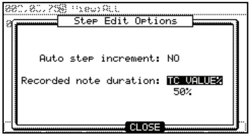
Duration of recorded notes' field
You can determine how the length that a pad (MIDI keyboard) is pressed affects the event to record during step recording.
AS PLAYED
The length that a pad (or MIDI keyboard) is pressed will be applied to the event.
When you hit a pad (MIDI keyboard), the metronome sound will start automatically. Refer to the metronome sound to set the length to press a button. When you release a pad (MIDI keyboard), the length that a key was pressed will be entered in the 'D (duration)' field.
TC VALUE%
When this is selected, the duration of events recorded in 'Step Record' mode will be automatically set to a percentage of the Timing Correct Setting. For example, if Timing Correct is set to 1/8th notes, a TC VALUE% of 50% will set the duration of each event to one-half the length of the Timing Correct setting. In this case, the length of each recorded event will be 16th notes.
Setting a TC VALUE% of 100% will insert events equal to the Timing Correct length.
Real time recording
In the GRID EDIT mode, you can record the sequence data in real time by pressing [REC] or [OVERDUB] and pressing [PLAY] at the same time.
Note: The event you recorded by real time recording displays on the grid after stopping the recording.
Chapter 7: SONG Mode
In SONG mode, you can set the order of multiple sequences and play them in a series. SONG mode is useful when you are creating a song by combining short sequences. You can check the structure of an entire song while working, so you can finish the song easily.
You can also perform direct to Hard Disk recordings here in SONG mode as well. For more on Hard Disk recording, see HD RECORD on page 61.
Note: MIDI recording is disabled in SONG Mode.
Structure of a song
The MPC5000 can handle up to 20 songs. Each song has 250 steps. You can create a song by assigning sequences to each step in the list. For each step, you can assign a sequence, and also set the number of times the MPC5000 should repeat the sequence. You can create a song in the SONG mode, which can be accessed by pressing [MODE] and [PAD 15].
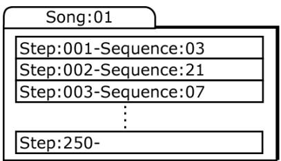
Screens
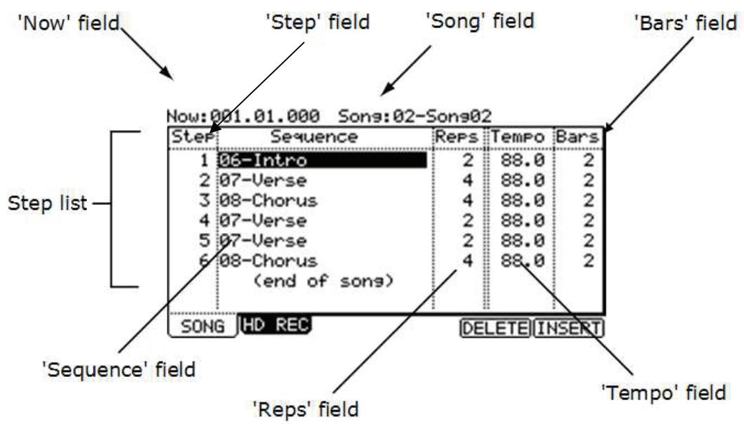
Now' field
The time display on the upper left corner on the screen is the 'Now' field. The 'Now' field always displays the current position of a sequence. This is the same as the 'Now' field in the MAIN page.
'Song' field
You can set the song number in this field. The song name will be displayed to the right of the number. If there is an unused song, it is displayed as (unused).
Step list
The list that is displayed below the 'Now' field and the 'Song' field is the step list, which is used to assign the sequences to each step. Pressing the down cursor button when the 'Now' field or the 'Song' field is selected moves the cursor to the step list. When there are many steps with different sequences assigned, you can scroll through the list with the up/down cursor buttons. Pressing the left cursor button in the 'Step' field of the step list moves the cursor to the 'Now' field.
Stepfield
This field displays the step number. You can scroll through the list by turning the [DATA] wheel.
Sequence' field
You can assign the sequences in this field by turning the [DATA] wheel.
Reps' field
You can set the number of times to repeat the sequence.
'Tempo' field
This field displays the tempo of the selected sequence. You can change the tempo of the sequence, but if you are using the same sequence in another step, the tempo of that sequence will be changed as well.
'Bars' field
This field displays the number of bars of the selected sequence. This field only displays the number of bars; you cannot make any changes in this field.
Creating a song
- Press [MODE] and then [PAD 15] (SONG).
The SONG page will be displayed. - In the 'Song' field, select a song whose name is (unused).
- Move the cursor to (end of song) and select the sequence to play first using the [DATA] wheel.
Turning the [DATA] wheel creates the new step and you can select a sequence. Then the new song will be created and its name will change from (unused) to Song## (## indicates the song number).
- In the 'Reps' field, set the times to repeat a sequence.
The MPC5000 will repeat the sequence the number of times set here before starting to play the next step.
1-99
The MPC5000 will repeat the sequence the selected number of times.
HOLD
The MPC5000 will repeat the sequence until you press the [F4] (Sudden) or the [F6] (NEXT) button.
If you set the 'Reps' field to 0, the MPC5000 will finish the play back after the previous step. It will not play the next step.
- Select the '(end of song)' field by pressing the down cursor button, and select the sequence that you want played back next.
Assign the sequences in the desired order by repeating the steps 03 and 04.
- Press [PLAY START].
The assigned sequence will be played in the selected order.
- Deleting a step
To delete a step in the list, proceed as follows.
- Select the step that you wish to delete.
You can select the step by using the up/down cursor buttons in the step list.
- Press [F5] (DELETE).
The selected step will be deleted and the following steps will be moved forward.
Inserting a step
To insert a step in a song, proceed as follows.
- In the Step list, select a step that you wish to insert a new step into.
The new step will be inserted before the selected step.
- Press [F6] (INSERT).
A new step with the same contents as the select step will be inserted right before the selected step.
Playing a song
You can play the song by pressing [PLAY START]. To play from the middle of the song, select the position that you wish to start the playback, using the cursor, and press [PLAY].
During the playback, the function buttons will change as follows.
[F5] (SUDDEN).
If you press this button during the playback, the MPC5000 will skip to the next step before it finishes the current sequence.
[F6] (NEXT)
If you press this button during the play back, the MPC5000 will skip to the next step after it finishes playing back the current sequence regardless of the number of repeats in the 'Reps' field.
Tip: If HOLD is selected for a step in the 'Reps' field, the MPC5000 will not go to the next step until you press the [F5] (SUDDEN) button or the [F6] (NEXT) button.
Other features in SONG Mode
Changing the song name
- In the 'Song' field of the SONG page, select a song that you wish to change the name of.
- Press [WINDOW].
The Song window will be displayed.
- In the 'Song name' field, enter the new name.
For more information for setting the name, see the 'Setting Names' section on Page 18.
- Press [F4] (CLOSE).
It closes the window and goes back to the SONG page.
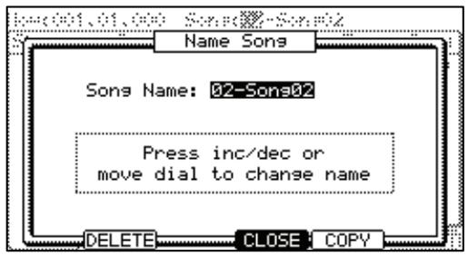
Copying a song
To copy a song to another song, proceed as follows.
- In the 'Song' field of the SONG mode, select a song that you wish to copy.
- Press [WINDOW].
The Song window will be displayed.
- Press [F5] (COPY).
The Copy Song window will be displayed.
- In the 'Song' field (below), select a song that you wish to copy the selected song to.
- Press [F3] (DO IT).
The MPC5000 will start copying the song. To cancel the operation, press [F4] (CANCEL) instead.
- Deleting a song
To remove the selected song from the memory of MPC5000, proceed as follows.
- In the 'Song' field of the SONG mode, select a song that you wish to delete.
- Press [WINDOW]
The Song window will be displayed.
- Press [F2] (DELETE)
The Delete Song window will be displayed.
- Press [F5] (DO IT)
This deletes the selected song and changes its name to 'unused'.
Deleting all songs
You can delete all the song data in the memory at one time. Proceed as follows.
- In the SONG mode, select the 'Song' field and press [WINDOW]. The Song window will be displayed.
- Press [F2] (DELETE) The Delete Song window will be displayed.
- Press [F3] (ALL SG) The Delete ALL Songs window will be displayed.
- Press [F5] (DO IT) All the songs will be titled (unused).
Setting all sequences to the same tempo
Each sequence has its own tempo. When you are creating a song in the Song mode, it is useful to change all the sequences to have the same tempo at once. With this feature, you can change all the sequences that you are using for a song to the same tempo at once.
- In the 'Tempo' field of the step list, press [WINDOW]
The Tempo Change window will be displayed.
- Press [F5] (FIX)
The Fix Tempo window will be displayed.
- In the 'Fix tempo' field, select the desired tempo.
- Press [F5] (DO IT)
All the sequences used in the song will be set to the tempo that is set in the 'Fix tempo' field.
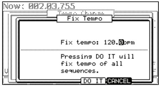
■ Ignoring tempo change events in a sequence
You can set the MPC5000 to ignore tempo change events that are set in a sequence.
- In the 'Tempo' field in the step list, press the [WINDOW] button.
The TEMPO CHANGE window will be displayed.
- Select a setting in the 'Ignore tempo change events in sequence' field.
NO
The MPC5000 will execute the tempo change events in the sequence.
YES
The MPC5000 will ignore the tempo change events in the sequence.
- Press the [F4] (CLOSE) button.
This closes the window.
Converting a song to a sequence
You can convert a song to one long sequence. You can record or overdub to the converted sequence in the MAIN mode like other sequences. You can also edit the sequence in the STEP EDIT mode or the SEQ EDIT mode.
- In SONG mode, select any sequence shown in the Step List and press [WINDOW].
The CONVERT SONG window will be displayed. - In the 'Song' field, select the song that you wish to convert.
- In the 'Sequence' field, select the destination sequence.
- In the 'Track status' field, select the track status after conversion to a sequence.
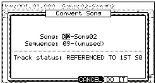
REFERENCEED TO 1ST SQ
The setting data (such as MIDI output, Mixer setting, Tempo, etc) of each track in the 1st Sequence of the Song will be used for all tracks in the following sequences.
MUTE TRACKS Ignored
The muted tracks in the sequences of the Song will not be converted.
MERGED ON MIDI CHANNEL
The track in the sequence of the Song will be merged to the track according to the MIDI output channel.
For example:
The track data of MIDI output channels 1A-16A will be merged to tracks 1-16.
The track data of MIDI output channels 1B-16B will be merged to track 17-32.
The track data of MIDI output channels 1C-16C will be merged to track 33-48.
The track data of MIDI output channels 1D-16D will be merged to track 49-64.
Note: When using MERGED ON MIDI CHANNEL, if the track is set to OFF in the 'MIDI' field in the MAIN page, the data in the track will not be merged after Convert Song to Seq. If you wish to convert the tracks for an internal program, set the MIDI output channel for the track temporarily.
- Press [F5] (DO IT)
The song will be converted to a sequence.
Note: during Song Conversion
(When selected 'REFERENCEED TO 1ST SQ' and 'MUTE TRACKS Ignored')
When you convert a song, the specific settings used in each track within the sequence, such as track type, MIDI channel setting, selection of the program, etc, will be set to the values that you set in the sequence in the first step of the song. If the track setting of the sequence in another step is different from those in the first song step, the song may not be converted properly. To avoid this, it is better to make the track settings and the order of each sequence the same. For more information on how to change the order of the tracks, see the 'Changing the order of the tracks' section on page 30.
Chapter 8: HD RECORD Mode
Another function that is new to MPC line with the MPC5000 is Hard Disk Recording. Using the [RECORD IN], [PHONO IN], or [S/PDIF IN] jacks on the back of your MPC, you can record performances, such as vocals, live guitar, live keyboards -just about anything you can imagine - to your song. Up to eight tracks can be recorded per song.
Since this audio is recorded directly to the Hard Drive, no RAM is used, so the only limit to how much you can record is the size of the Hard Drive. Many hours of sound can be recorded on the MPC5000's Hard Drive. You can also apply effects to your Hard Disk tracks, edit your recorded audio, and mix down your song along with your song to create a finished product.
Adding Hard Disk Tracks to a Song
To add a Hard Disk track to your current song, do the following.
- Press [MODE] and [PAD16] (HD RECORD) to enter the HD REC page.
The following page will be displayed as shown. Here, you can select whether you would like to add audio tracks to the current song.
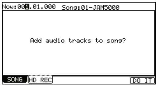
Note: this page is also accessible from SONG mode by pressing [F2] (HD REC).
- Select a song you would like to add Hard Disk tracks to in the 'Song' field.
See page 55 for more information on SONG mode.
- Press [F6] (DO IT).
This will add audio tracks to the current song, and the screen will be displayed as shown on the right. For recording audio tracks, see the next section.
![AKAI MPC5000 - Note: this page is also accessible from SONG mode by pressing [F2] (HD REC). - 1](/content/2025/01/152537/images/786345676a179b5c1afdd6b3bdb5416c3a96d8ece9779a62a50adad3297f46a3.jpg)
Note: an important thing to note is that once audio tracks are added to a song, when attempting to select another song, you will be prompted to save the current song if anything regarding the current song has changed. This is to avoid wasted hard drive space. Unsaved audio will be deleted when you switch to a different song.
■ About the RECORD Page.
Many recording functions are handled here on this page. Track arming for recording, selecting inputs and monitoring of levels are all done on this page.
Now
This is a display of time. This is the same as the 'Now' field on the MAIN page.
NOW:012.03.960 S
Song
This is where the name of the current song is displayed. Pressing the [WINDOW] button on this page will allow you to rename the song. For more on naming, see page 18.
Song-11-16Character Name
Source
This parameter selects whether the recording tracks will use the analog [RECORD IN] jacks, or the [DIGITAL] S/PDIF input as a source. You can also resample the MAIN OUTS, or resample any pair of ASSIGNABLE MIX OUTS.
Now:681.01.000 30 Source:ANALOG
Rec In L/R to Track
Each of these settings determine which Hard Disk track will be recorded to for each input. Any of the eight tracks are available for recording.
Rec In L to Track: 8
Rec In R to Track: 4
[F5] (L ARM) and [F6] (R ARM)
These buttons are used to arm the tracks for recording. When selected, the button will darken, and the tracks indicated in the corresponding 'Rec In' fields will be recorded to. The incoming audio will be monitored through the [STEREO OUT] jacks, so you can hear what you are recording. When unselected, you will be able to hear back what was recorded.
![AKAI MPC5000 - [F5] (L ARM) and [F6] (R ARM) - 1](/content/2025/01/152537/images/e275a55296859651a56acb5db88a6078176aa304219193ed403fb311d143822f.jpg)
Track Matrix
The Track Matrix shows which track the left and right inputs are being recorded to, allowing for quick reference. These will illuminate when the selected track is armed.
Recording Hard Disk Tracks
To record your first Hard Disk tracks, do the following.
- Add Hard Disk tracks to the song you wish to record to.
This is accomplished as detailed in the previous section, 'Adding Hard Disk Tracks to a Song' on page 61.
- Select the 'Source' field and select the desired input source.
For our example, let's choose 'ANALOG'.
- Select which tracks the left and right inputs should be recorded to by selecting the corresponding tracks in the 'Rec In L/R' fields.
For our example, let's select tracks 1 and 2.
-
Arm the desired tracks in the song by pressing the [F5] (L ARM) and [F6] (R ARM) buttons.
-
Play the source you wish to record.
Adjust the [GAIN] knob to get the best volume level without clipping or distortion.
- Press [REC] and [PLAY START].
This will start the recording process.
- Record your performance along with your song.
Press the [STOP] button to end the recording when you are finished.
Recording additional tracks
To record additional tracks to the song, do the following.
- Select the 'Rec In L/R' fields and select the next tracks you wish to record to.
For our example, let's choose channels 3 and 4.
-
Arm the tracks by pressing the [F5] (L ARM) and [F6] (R ARM) buttons.
-
Play the source you wish to record.
Adjust the [GAIN] knob to get the best volume level without clipping or distortion.
- Press [REC] and [PLAY START].
This will start the recording process.
- Record your performance along with your song.
Press the [STOP] button to end the recording when you are finished.
Viewing Recorded Tracks
To view the tracks you've recorded, press [F4] (TkVIEW). Here, you will see each of the eight tracks, and waveform data recorded to each track. Like the RECORD page, the 'Now' and 'Song' fields are available.
Edit
This check box selects which tracks will be edited. This selection can be navigated to by using the [CURSOR] buttons, and checked or unchecked by turning the [DATA] wheel. In the example to the right, tracks 1 and 2 are selected for editing.
Arm
This read-only column shows you which tracks are set to be recorded in the RECORD tab.
ST and END Times
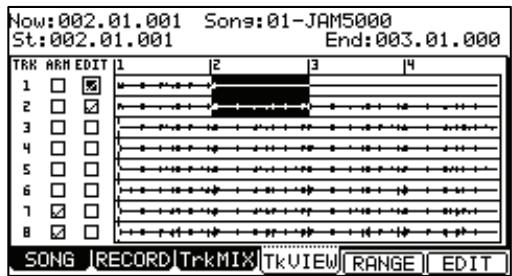
This is where the range for selected edit functions are selected. The time range selected will be displayed by highlighting in white. For example, in the picture shown, the range of 002.00.001 to 003.00.000 is selected. You can edit these fields by scrolling with the [DATA] wheel. If you press the left or right [CURSOR] buttons while holding [SHIFT], you can move the cursor to higher points within the numeric display to allow for quicker value selection. You can also enter the value directly with the numeric keypad.
Additionally, the start point can be edited by moving the [Q1] Q-LINK slider while the field is selected.
Note: only tracks selected for editing will be highlighted.
Selecting the View Range
You can zoom in to get a better look and more accurately set start and end points for editing. This allows you to view the entire song, or just view a single bar.
To Select the View Range, do the following:
- Press [F5] (RANGE)
The View Range page will be displayed.
- In the "Number of Bars" field, select the desired view range.
You can select a view range as small as one measure, up to the entire range of the song.
- Press the [F4] (DO IT) button.
This will return you to the 'Track View' page, with the selected range displayed.

Viewing Individual Disk Tracks
You can zoom in on the waveforms for fine editing individual tracks to get a better look and more accurately set start and end points for editing.
To finely view a recorded track, do the following:
- Select the 'Start' or 'End' field.
Fine View will zoom to the start or the end point depending on which you select.
- Press the [WINDOW] button.
The FINE page will be displayed.
- Zoom out or in by pressing the [F2] (ZOOM-) and [F3] (ZOOM+) buttons, respectively.
The screen will zoom in or out, with the point selected in the 'St' field justified to the left.
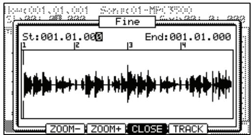
- Select the 'End' field and Zoom out or in by pressing the [F2] (ZOOM-) and [F3] (ZOOM+) buttons, respectively.
The screen will zoom in or out, with the point selected in the 'End' field justified to the right.
Choosing the Track to View
You can select other tracks to view by doing the following:
- Press and hold the [F5] (TRACK) button.
The screen will change as shown on the right, with a popup to select which track to view. - Select the track you would like to view by scrolling with the [DATA] wheel.
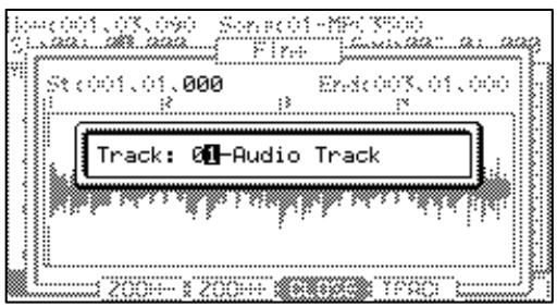
Editing Hard Disk Tracks
Various edit functions are able to be performed on recorded Hard Disk tracks. To select the tracks to be edited, do the following.
Selecting multiple tracks
- On the TkVIEW page, select the first track to be edited.
- Select the 'Edit' field
You can navigate to field by using the [CURSOR] buttons.
- Place a check in this track's 'Edit' field.
- Repeat steps 1-3 for each track you wish to edit.
- Using the 'St' and 'End' fields, select the time range you wish to edit.
You can edit this field by scrolling with the [DATA] wheel. If you press the left or right [CURSOR] buttons while holding [SHIFT], you can move the cursor to higher points within the numeric display to allow for quicker value selection. You can also enter the value directly with the numeric keypad.
Additionally, the start point can be edited by moving the [Q1] Q-LINK slider.
- Press the [F6] (EDIT) button.
This will open the AUDIO EDIT page. For information on the individual edit functions, see page 64.
Fine Editing of a Single Track
- Select the track you wish to edit.
- Press the [F5] (ZOOM) button.
When editing from the Zoom page, only the selected track will be edited.
- Using the 'St' and 'End' fields, select the time range you wish to edit.
You can edit this field by scrolling with the [DATA] wheel. If you press the left or right [CURSOR] buttons while holding [SHIFT], you can move the cursor to higher points within the numeric display to allow for quicker value selection. You can also enter the value directly with the numeric keypad.
Additionally, the start point can be edited by moving the [Q1] Q-LINK slider.
- Press the [F6] (EDIT) button.
This will open the AUDIO EDIT page. For information on the individual edit functions, see page 64.
Individual Edit Functions
When the [F6] (EDIT) button is pressed, the AUDIO EDIT page is opened. This page differs depending on the edit function selected. The following parameters are shared among all the pages.
Tracks
This displays what tracks are to be edited. This displays the tracks that were selected on the TKVIEW page.
Edit
This field selects the different edit functions. The different edit functions are explained individually below.
Start/End

This is the start and end point for the edit function to be applied. This will default to what was set on the TKVIEW or ZOOM pages, but can be f
The following edit functions are available to be applied to recorded audio tracks.

Gain
This function will increase or decrease the amount of volume for the selected tracks and ranges. Press [F5] (DO IT) to execute the selected edit function. Press [F4] (CANCEL) to close the AUDIO EDIT page without affecting the audio.
Up to 18dB or gain can be added or subtracted to a track at once.
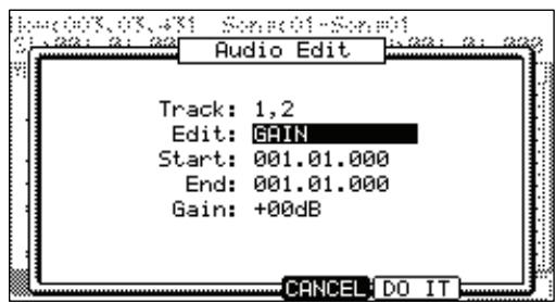

Fade
This function sets an automatic fade in or out to an audio track. The following fade types are available: Linear Fade In / Out
This selection fades in or out the audio with a linear curve. A linear curve will go from start to end with no curve, creating a straight line.
Logarithmic Fade In / Out
This selection fades in or out the audio with a Logarithmic curve. A logarithmic curve will quickly rise, and then even out for the middle section, surging quickly again as it nears the end.
Exponential Fade In / Out
This selection fades in or out the audio with an Exponential curve. An exponential curve will slowly rise in the beginning, and then quickly rise for the middle section, and then slowing again as it nears the end.


Cut / Copy / Pasting Tracks
Cut and Copy allows you to duplicate a selected portion of your track. You can then paste this portion elsewhere in your song using the 'Paste' process. When using the 'cut' function, the selection copied is deleted. When 'Copy' is selected, the original is left intact.
To copy a section of audio into another track, do the following:
- Select the track you wish to copy by checking the 'Edit' field.
- Select the entire range of the track.
Scroll with the [DATA] wheel on the 'End' field to select the entire track. This can also be done by moving the [Q-LINK 01] slider while holding down the [AFTER] button.
- Press [F6] (EDIT)
This will open the AUDIO EDIT page.
- In the 'Edit' field, select 'Copy'.
- Press [F5] (DO IT) to copy the audio selection.
This will return you to the TKVIEW page.
- Select the track you wish to paste the copied data into.
- Press [F6] (EDIT)
Note that the 'Edit' field defaulted to 'Paste'. If paste is not selected in 'Edit', then select it now.
- Choose how you would like your track pasted with the 'Paste Type'
- In the 'Number of copies' field, select the number of consecutive copies you would like to paste.
- Press [F5] (DO IT) to execute the paste.
The audio data you copied will now be pasted into place.
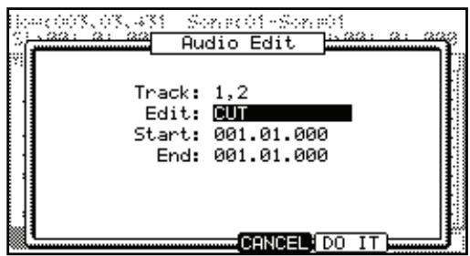
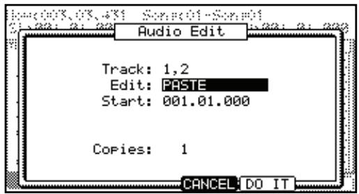
■Normalize
Normalize is a process that analyzes your recording and adjusts the volume to make the loudest part of your audio track equal to 0 dB (i.e., the loudest possible level).
Press [F5] (DO IT) to execute this function.
Silence
This process allows you to silence a section of a track, or silence an entire track. Press [F5] (DO IT) to execute this function.
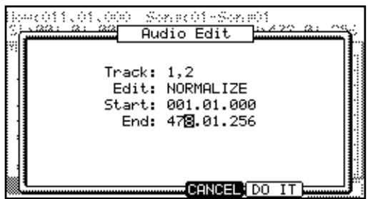
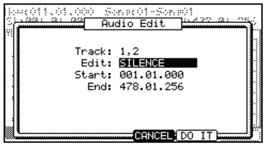
Importing and Exporting Tracks
The MPC5000 can import .wav files as tracks to be used in your song, and export Hard Disk tracks to allow for editing with a computer, or even loading the exported track as a sample.
■ Importing
To import an audio track as a Hard Disk track, do the following.
- Press [MODE] + [PAD 16] to enter HD RECORD mode.
- In the 'Song' field, select the song you wish to import an audio track into.
If no Hard Disk tracks are added to the current song, add audio to this song as detailed in the section entitled 'Adding Hard Disk Tracks to a Song' on page 61.
- Press the [F4] (TkVIEW) button to open the TRACK VIEW tab.
- Select the track you wish to import the file in to, and select the EDIT checkbox.
- Press [F6] (EDIT) to open the AUDIO EDIT page as shown on the right.
- In the 'Edit' field, select 'Import Track'
- In the 'Destination' field, select the track to import your track to.
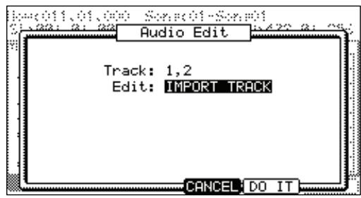
Note: if the destination track has audio recorded to it already, this audio will be deleted and replaced with the imported track!!
- Press [F5] (DO IT)
This will open the following window. Here, you can select the track you wish to load.
- Choose the drive and directory for the file to be imported.
You can navigate to different folders using the up and down [CURSOR] buttons and open and close folders by pressing the left or right [CURSOR] buttons.
For more on loading files and browsing drives, see 'Saving and Loading (DISK Mode)' on page 149.
- Press [F5] (DO IT) to import the selected file.
This will import the selected file into the selected track.
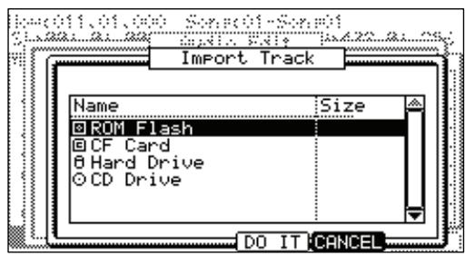
Exporting
To Export an audio track as either a 16 or 24-bit wave file to the Hard Disk, do the following.
- Press [MODE] + [PAD 16] to enter HD RECORD mode.
- In the 'Song' field, select the song you wish to export audio tracks from.
- Press the [F4] (TkVIEW) button to open the TRACK VIEW tab.
- Press [F6] (EDIT) to open the AUDIO EDIT page as shown on the right.
- In the 'Edit' field, select 'Export Track'
- In the 'Track' field, select the track to Export.
You can choose any of the eight Hard Disk tracks to export, or you can export all of them by selecting 'ALL'.
- For 'Format', choose 16 or 24-bit.
If you will be burning this track to a CD, select 16-bit. If you will be importing the file into a 24-bit capable audio application, select 24-bit. - Press [F5] (DO IT)
This will open the window shown to the right. Here, you can select device and destination you wish to save the exported track to. - In the 'Save to' field, choose the drive you wish to export track to.
- Select the directory to save to in the 'File browser' field.
You can navigate to different folders using the up and down [CURSOR] buttons and open and close folders by pressing the left or right [CURSOR] buttons.
For more on loading files and browsing drives, see 'Saving and Loading (DISK Mode)' on page 149.
- Press [F5] (DO IT) to export the selected file.
This will export the selected file into the selected directory.

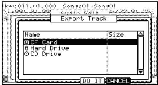
Mixing Hard Disk Tracks
Output level, pan and effects settings can all be set for each Hard Disk track. To access the Hard Disk track mixer, do the following.
- Press [MODE] + [PAD 16] (HD RECORD) to access the HD RECORD mode.
- Press [F3] (TRKMIX) to access the HARD DISK TRACK MIX page as shown on the right.
The Columns shown represent each of the eight Hard Disk tracks. Each Track Number will be displayed next to the LEVEL indicator in the LVL row.
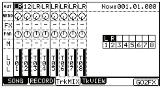
Setting Track Output
To set which out each Hard Disk track will be routed to, do the following.
- In HD RECORD mode, press [F3] (TRKMIX).
The TRKMIX page will be displayed.
Each column indicates Hard Disk tracks 1-8 and the currently selected track is highlighted. The row at the top is the 'OUT' field, where you where you will assign a track to a specific assignable output.
- Hit the pad that corresponds with the desired track.
The column for the selected track will now be highlighted.
You may also select each track by using the [CURSOR] buttons.
- Select the desired output in the OUT row.
You can use the [CURSOR] buttons to move to each field in MIXER mode, and you can adjust each level with the [DATA] wheel. The following choices are available:
ST
The track will be sent to the [STEREO OUT]. The track can be panned.
1/2 to 7/8
The track will be output to the corresponding [ASSIGNABLE MIX OUT]. The track can be panned.
1 to 8
The track will be output in MONO to the corresponding [ASSIGNABLE MIX OUT] output. Panning is disabled.
Tip: You can also easily change the settings for tracks by using the Q-LINK controls. For more information on using the Q-LINK with MIXER Mode, see 'Using Q-LINK Controls with MIXER Mode' on page 81.
Track Matrix
The Track Matrix shows which track the left and right inputs are armed as set in the RECORD page, allowing for quick reference.
Setting the level and pan of a Track
- Press [MODE]+[PAD 16] (HD RECORD) to access the HD RECORD mode.
- Press [F3] (TRKMIX) to access the HARD DISK TRACK MIX page.
- Hit the pad corresponding to the desired track.
The column of the selected track will be highlighted. You can select several tracks by hitting pads while holding down the [SHIFT] button.
Tip: When you select several tracks and change a parameter (Level or Pan), the parameter on each pad will be changed relative to the current setting.
04. Adjust the PAN value in the PAN row.
The fourth row down is labeled 'PAN'. Here is where the pan setting of each track is set. The knob graphic indicates the pan setting. The location of the line within the circle indicates the current pan setting.
05. Adjust the Level value in the LVL row.
The bottom row is labeled 'LVL'. Here is where the level setting of each track is set. The dark line in each column represents the relative level of each track, much like faders on a mixing board. You can use the [CURSOR] buttons to move to each field in MIXER mode, and you can adjust each level with the [DATA] wheel.
Tip: You can also easily change the settings for tracks by using the Q-LINK controls. For more information on using the Q-LINK with MIXER Mode, see 'Using Q-LINK Controls with MIXER Mode' on page 81.
■Assigning effects to a Track
With the MPC5000, you can route HD tracks to any of four (4) internal FX buses. In this section, we will discuss routing tracks to the FX buses.
Note: Each FX bus can be assigned to a separate output, allowing for the dry signal and the affected signal to be routed independently. For more information, see page 146.
- In HD RECORD mode, press [F3] (TRKMIX).
The TrkMix page will be displayed. Each column indicates tracks 1 though 8 from the left to right and the currently selected track is highlighted.
- Hit the pad corresponding to the desired track.
The column of the selected track will be highlighted.
- Select which FX Bus to send the track to.
To adjust this value: simply move the cursor to the FX row, and use the [DATA] wheel.
OF
No effect will be used.
1 to 4
The effect bus number selected (1 to 4) will be used. The track sound will be sent to the selected effect section.
- Adjust the SEND level by selecting the control in the SEND row by turning the [DATA] wheel.
The display in the SEND row indicates the output setting. The graphical knob display in the FX row indicates the current send level. Increasing this level will increase the amount of effect for the selected track.
Note: the SEND knob in the SEND row will be disabled if the selected FX bus has DIRECT OUT Disabled. For more information on DIRECT OUT, see page 134.
Note: Each FX bus can be assigned to a separate output, allowing for the dry signal and the affected signal to be routed independently. For more information, see page 146.
Muting a Track
Each Hard Disk track can be muted from TRKMIX mode. To mute a Hard Disk track, do the following:
- In the HD RECORD mode, press [F3] (TRKMIX).
The TRKMIX page will be displayed.
Each column indicates track 1 though 8 from the left and the currently selected track is highlighted.
- Hit the pad corresponding to the desired track.
The column for the selected track will now be highlighted.
- In the MUTE row (Displayed as 'M'), scroll with the [DATA] wheel to select one of the following.
Track will play as normal
M
Track is muted
Additionally, if this field is scrolled while the [SHIFT] button is held down, the following is available:
s
Track is soloed.
Using Q-LINK Controls with MIXER Mode
In addition to the [DATA] wheel, the Q-LINK controls can be used to change settings within TRKMIX mode. When track 1-4 is selected, the four Q-LINK knobs and sliders will control tracks 1-4. When track 5-8 is selected, the four Q-LINK knobs and sliders will control tracks 5-8. The selected tracks are indicated with a bold line.
The function of each Q-LINK control is detailed in the section entitled 'Using Q-LINK Controls with MIXER Mode' on page 81.
Mixer Automation
The MPC5000 can record information such as Level and Pan changes so that they will automate during sequence play back. Now:813-83-246 Song 1-16 Character Name
- In the HD RECORD mode, press the [F3] (TRKMIX) button.
- Press the [WINDOW] button to open the HD MIXER SETUP page.
- In the 'Record Mix Changes' field, select YES with the [DATA] wheel.
If you set this field to YES and change the LEVEL, SEND, MUTE, or PAN in the TRKMIX page while recording in SONG mode, the changed data will be recorded into the song. The song will be played with changing the Level or the Pan as you did during the recording. The mix data recorded in the song is displayed in STEP EDIT page as follows and you can edit it the same as other MIDI event.
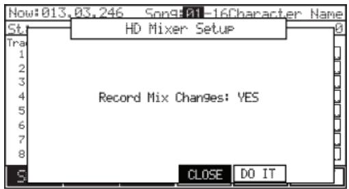
Note: Level event shares with Level of Q-LINK.
Mixdown
The MPC5000 can mix down songs, including internal sounds, Hard Disk tracks, and effects into a single file. Using this function, a 16 bit / 44.1 kHz stereo wav mixdown of the current song can be created, ready to burn to CD as your final master, or you can bounce the tracks to a two track mix in the current song.
Note: only parts assigned to the Main Outputs will be applied to the mixdown. Programs, Effects, and Hard Disk Tracks assigned to the [ASSIGNABLE MIX OUTS] will not be mixed.
■ Mixdown to File
To perform a mixdown of the current song to an audio file, do the following:
- Select the RECORD tab by pressing [F2].
- Press the [WINDOW] button to open the MIXDOWN page.
The page shown on the right will be displayed.
- In the 'Destination' field, select 'Save as file'.
- In the 'Filename' field, set the name of the mixdown file you will be creating.
For more information on naming, see page 18.
- For 'Format', choose 16 or 24-bit.
If you will be burning this track to a CD, select 16-bit. If you will be importing the file into a 24-bit capable audio application, select 24-bit.
- Select what you would like to be included in the mixdown.
You can select from the following parameters. Each parameter can be set to 'YES' or 'NO'.
Sequence Tracks
Internal Sequence tracks will be included in the mixdown. This includes all tracks created using internal programs such as drums, virtual analog synth programs, etc.
Note: MIDI tracks will not mix down, as their sources are external to the MPC5000. In order to mix down external devices with the MPC5000, they must be plugged into the [RECORD IN] and mixed down as Input Thru.
Recorded Audio
The eight Hard Disk tracks will be included in the mixdown.
Effects
Effects will be included in the mixdown.
Mixer Automation
Mixer automation will be performed on the mixdown.
Input Thru
The input thru will be recorded as the mixdown is performed.
Note: The level of the source being played via Input Thru is controlled by the [REC GAIN] knob. Make sure the level is set properly before mixing down.
- Press [F5] (DO IT)
The MPC5000 will begin mixing down the track. You will be able to monitor the mixdown by listening to either the [STEREO OUT] or by listening through the [PHONES] jacks. At any time, you may cancel the mixdown by pressing the [F4] (CANCEL) button.
When the mixdown is complete, you will be asked for a location to save the mixdown.
- Select the folder and drive to save the mixdown to.
- Press [F5] (DO IT).
The mixdown will be saved.
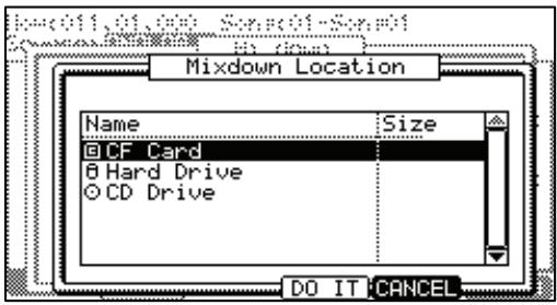
Chapter 9: Functions of a Pad
The MPC5000 has 16 drum pads. The pads perform various functions besides making sounds when hit. In this section, you will learn about various functions of the pad.
Playing with pads
By assigning the sounds in memory to a pad, you can play those sounds.
Below are some useful functions when playing with pads.
Switching pad banks
The MPC5000 has 16 pads, but you can play up to 64 samples by switching between the four pad banks.
The LED of the currently selected pad bank (from banks A through D) is turned on. By pressing the desired [PAD BANK] button, you can switch pad banks.
Full level function ([FULL LEVEL] button)
You can control the level of the sound by the velocity used to hit the pads, but if you press the [FULL LEVEL] button, the MPC5000 will play the sample at the maximum level regardless of the velocity.
If you press the [FULL LEVEL] button, the LED will be lit, and the full level function will be activated. To deactivate this function, press the [FULL LEVEL] button again.
![AKAI MPC5000 - Full level function ([FULL LEVEL] button) - 1](/content/2025/01/152537/images/ee88995820b3d32fb4ccd01263d7e1e1bf0f609cf3cc30a78082be789fceac54.jpg)
16 levels function ([16 LEVEL] button)
You can play a sound using 16 parameter levels assigned to the 16 pads.
- Hit the pad that you wish to play in 16 levels.
- Press the [16 LEVELS] button.
The Assign 16 Levels window will be displayed.
The 'Pad' field displays the pad you selected in step 1.
- In the 'Type' field, select the type of the parameter that you wish to play in 16 levels.
You can select the following parameters;
![AKAI MPC5000 - levels function ([16 LEVEL] button) - 1](/content/2025/01/152537/images/c8fc00de1c834b4ca7bc7189f4ce1abafc3462e079ef7195cc945b731e2cfe38.jpg)
VELOCITY
The MPC5000 will play the velocity in 16 levels.
TUNE
The MPC5000 will play a single pad in a sample program by varying pitch in 16 levels by semitone.
FILTER
The MPC5000 will play the filter cutoff value in 16 levels.
LAYER
The MPC5000 will play the layer value in 16 levels.
DECAY
The MPC5000 will play the decay value in 16 levels.
ATTACK
The MPC5000 will play the attack value in 16 levels.
When TUNE is selected, the Original key 'Pad' field will be displayed. In this field, you can specify the pad that plays the original key pad.
- Press the [F5] (TurnON) button.
The window closes and the LED of the [16 LEVELS] button is turned on, which indicates you can play in 16 levels. Pressing the [16 LEVELS] button turns its LED off and deactivates the 16 levels function.
Tip: When you select VELOCITY in the 'Type' field, the velocity of the pad event can be played in 16 levels, but if you select an option other than VELOCITY, the note variation value will be played in 16 levels. The note variation data can change the value of a specific parameter when you play the pad's sample. For example, if you select TUNE in the 'Type' field, when you hit the pad, the note variation data of TUNE will be sent to the sampler section with the pad event, and the TUNE value will be changed according to the pad you played.
During Sequence recording, the Note variation data will be recorded with the note event and you can play back the sequence exactly what was played. The note variation value is also used for the Q-Link slider function.
Muting Sequence Tracks with Pads (Track Mute)
You can mute/unmute sequencer tracks in real time during playback by hitting the pads. This is useful when you have several instruments assigned to different tracks, so that you can play a song and switch tracks on/off using the pads while playing back your sequence.
- Press the [TRACK MUTE] button
- Press [F1] (TkMUTE)
This brings up the Track Mute page.
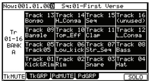
'Now' field
Like the 'Now' field in the MAIN page, this field displays the current time position of the sequence.
'Sequence' field
Like the 'Sequence' field in the MAIN page, you can select a sequence in this field.
Track list
The track list is displayed under the 'Now' field and the 'Sequence' field.
The track list displays the first 8 letters of the track name. The tracks are displayed according to the position of the pads; Track 1 on the lower left and track 16 on the upper right. You can display 16 pads at one time, but you can display 1 to 64 tracks by switching pad banks. The track whose track mute is set to off will be highlighted.
Operation
Hitting a pad when the track mute page is displayed switches the track mute setting of that track instead of playing the sound.
Solo Function
With the Solo function, you can play back only the selected track.
- Hit the pad that corresponds to the track that you wish to play, while pressing the [F6] (SOLO) button.
[F6] (SOLO) will be highlighted and MPC5000 will play only the selected track while it mutes the other tracks. You can switch the tracks to play, by hitting a pad.
- Pressing [F6] (SOLO) deactivates the solo function.
■ Selecting Instant Track Mute
The MP5000 has the ability to mute tracks using two different methods. Method one ignore Note On messages. This is how legacy MPC track muting has worked. This method allows samples and notes that are playing to finish playing through their entire length. This is useful when using loops, and you want to have a loop finish playing to the end of a measure, then not play the next time the sequence loops.
Method two is Instant Track Muting, which sends MIDI track volume. This is a method that is new to the MPC5000, which is useful for when you want to have the track muted immediately. The advantage of this method is that the loop will continue to play, but at zero volume, allowing the loop to continue playing when the track is unmuted. Using this method, stuttering, beat juggling between two loops, and other DJ style techniques can be employed.
To Turn on Instant Track Mute, do the following:
- From the MAIN page, select the 'MUTE' field.
- Press [WINDOW]
The MUTE EVENTS window will be displayed.
- Select the 'Instant Track Mute' field, and select the desired option.
ON
Tracks will be muted instantly by sending MIDI Volume.
OFF
Tracks will be muted like legacy MPCs, by ignoring Note Off events.
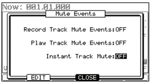
Setting the Track Mute in Solo Mode
Solo function switches the track mute setting temporarily. Turning off the solo function resets the track mute settings for each track to the same status as before the solo function was activated. However, you can also turn off the solo function while keeping the track mute setting unchanged. With this feature, you can make a performance starting with many tracks followed by only a simple rhythm track and then gradually add tracks.
Operation
When the solo function is on, press [F6] (SOLO) while holding the [SHIFT] button.
The Solo function will be deactivated and the mute setting for the track set to solo will be turned off. The setting for other tracks will be turned on.
Recording Track Mutes
The MPC5000 has the ability to record track mute events. Track mute recording is off by default. To turn on track mute recording, do the following:
- From the MAIN page, select the 'MUTE' field.
- Press [WINDOW]
The MUTE EVENTS page will open.
Select the 'Record Track Mute Events' field and change it to ON.
Also note that there is a convenient shortcut to the SEQ EDIT page here. Press [F2] (EDIT) to access the SEQ EDIT page. As further convenience, the 'VIEW' field in SEQ EDIT is set to TRACK MUTE automatically when SEQ EDIT is accessed in this way.
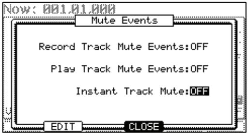
Once 'Record Track Mute Events' has been set to ON, pressing [PLAY] and [REC] or [OVERDUB] in the Track Mute page will allow track mute events to be recorded. Track mute events are only recorded when in the Track Mute page. Timing Correct settings will affect the recording of track mute events.
■ Ignoring Track Mute Events
To hear your sequence without playing back recorded or inserted track mute events, do the following:
- From the MAIN page, select the 'MUTE' field.
- Press [WINDOW]
The MUTE EVENTS page will open.
- Select the 'Play Track Mute Events' field and change it to OFF.
This will allow you to play back sequences while ignoring track mutes. To play track mute events in your sequences, set this field to ON.
Track Mute Groups
Pads can be grouped together, so hitting one pad will affect the other pads in the same group. TRACK MUTE GROUPS are accessed by pressing [F2] (TkGRP) from the Track Mute page.
To add a pad to a group, do the following:
- Press a pad. For an example, press PAD A01
The mute group selection for [PAD01] is selected.
- Change the selection from OFF to 1.
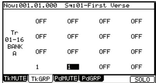
- Press another pad. For example, press PAD A02
The mute group selection for [PAD02] is selected. - Change the selection from OFF to 1.
- Press [F1] (TkMUTE) to return to the TRACK MUTE page.
- Play PAD A01
Notice that now PAD A02] mutes along with PAD A01. Up to 16 different mute groups can be created.
Note: When a pad is pressed while holding the [SHIFT] button, the track mute status of only the pressed pad is changed, and mute group settings are ignored.
Muting Individual Samples from a Program with Pads (Pad Mute)
You can mute/unmute individual sounds in a particular program on a particular track in real time by hitting the pads. This is useful when you have several samples assigned to different pads and you wish to remove a particular sound, or isolate specific drum hits.
- Press the [TRACK MUTE] button
- Press [F3] (PdMUTE)
This brings up the Pad Mute page.
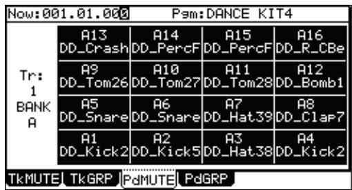
'Now' field
Like the Now' field in the MAIN page, this field displays the current time position of the sequence.
'Prg' (Program)' field
This displays which program is being affected with pad mute.
'Trk' field
Displays which track number is currently being affected.
The 16 blocks displayed represent the pads. The pad whose sample mute is set to off will be highlighted. Using the 'Trk' field, it is possible to have the same program muted different ways for multiple tracks.
Operation
Hitting a pad when the pad mute page is displayed switches the pad mute setting from off to on for that pad on the selected track, instead of playing the sound.
Pad Mute Groups
Pads can be grouped together, so hitting one pad will affect the other pads in the same group. PAD MUTE GROUPS are accessed by pressing [F4] (PdGRP) from the Track Mute page.
To add a pad to a group, do the following:
- Press a pad. For an example, press PAD A01
The mute group selection for [PAD01] is selected.
-
Change the selection from OFF to 1.
-
Press another pad. For example, press PAD A02
The mute group selection for [PAD02] is selected.
-
Change the selection from OFF to 1.
-
Press [F3] (PdMUTE) to return to the PAD MUTE page.
-
Play PAD A01
Notice that now PAD A02 mutes along with PAD A01. Up to 16 different mute groups can be created.
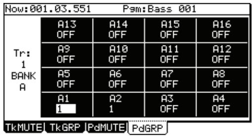
Note: When a pad is pressed while holding the [SHIFT] button, the track mute status of only the pressed pad is changed, and mute group settings are ignored.
Selecting a Sequence to Play with Pads
You can select a sequence that you wish to play next, by hitting the pads. This is useful for live performances, which change a song structure in real time. Also, you can check the relationship between sequences while you are working on a song with several short sequences.
Pressing the [NEXT SEQ] button brings up the next sequence page.
'Now' Field
Like the 'Now' field in the MAIN page, it displays the current time position of the sequence.
| Now:001.04.758 S4:01-Sequence 01 | ||||
| S401-16BANK | S4: 13Sequence | S4: 14Sequence | S4: 15Sequence | S4: 16Sequence |
| S4: 09Sequence | S4: 10Sequence | S4: 11Sequence | S4: 12Sequence | |
| S4: 05Sequence | S4: 06Sequence | S4: 07Sequence | S4: 08Sequence | |
| S4: 01Sequence | S4: 02Sequence | S4: 03Sequence | S4: 04Sequence | |
| 07-Sequence 07 SUDDENHOLD CLEAR | ||||
'Sequence' Field
Like the 'Sequence' field in the MAIN page, you can select a sequence in this field.
Sequence List
The sequence list is displayed under the 'Now' field and the 'Sequence' field.
The sequence list displays the first 8 letters of the sequence name. The sequences are displayed according to the position of the pads; Sequence 1 on the lower left and sequence 16 on the upper right.
You can display 16 pads at one time, allowing you to display 1 to 64 sequences by switching pad banks.
Note: you cannot select a sequence between 65 and 99 using pads, but you can select them in the 'Sequence' field.
Operation
- In the 'Sequence' field, select a sequence that you wish to play first.
- Start to play back the Sequence.
- Select another sequence that you wish to play next, using a pad.
The number and name of the selected sequence will be displayed below the Sequence list as shown in the image to the right. The MPC5000 will switch to the next sequence after it plays the current sequence to the end.
| Now:001.04.758 S4:01-Sequence 01 | ||||
| S401-16BANK | S4: 13Sequence | S4: 14Sequence | S4: 15Sequence | S4: 16Sequence |
| S4: 09Sequence | S4: 10Sequence | S4: 11Sequence | S4: 12Sequence | |
| S4: 05Sequence | S4: 06Sequence | S4: 07Sequence | S4: 08Sequence | |
| S4: 01Sequence | S4: 02Sequence | S4: 03Sequence | S4: 04Sequence | |
| 07-Sequence 07 | SUDDENHOLD CLEAR | |||
Tip: You can change the next sequence by hitting the pads until the current sequence ends.
Tip: When no other sequence is selected, the MPC5000 will continue to playback the current sequence over and over.
Tip: You can cancel the next sequence that is displayed below the sequence list, by pressing the [F6] (CLEAR) button.
SUDDEN Button
Normally, the MPC5000 will switch to the next sequence after it plays the current sequence to the end.
However, you can also switch to the next sequence before the MPC5000 finishes playing back the current sequence by pressing the [F4] (SUDDEN) button.
It is useful for the live performance, where you need to switch to the next phrase at a certain cue.
- Select the next sequence with the pads, and press the [F4] (SUDDEN) button.
The MPC5000 will switch to the next sequence at the point the button is pressed.
Tip: If you press the pad while holding the [F4] (SUDDEN) button, the MPC5000 will switch to the next sequence at the point the pad is hit.
■HOLD Button
Normally, when the next sequence is selected, the MPC5000 will switch to the next sequence after it finishes playing the current sequence. If you press the [F5] (HOLD) button, the MPC5000 will keep playing back the current sequence until you press the [F5] (HOLD) again. It is useful for the live performance, where you wish to change the phrase according to the response of the audience.
- Select the next sequence with the pad, and press the [F5] (HOLD) button.
The button will be highlighted and the MPC5000 will keep playing back the current sequence, instead of switching to the next sequence.
If you press the [F5] (HOLD) button again, the Hold function will turn off and the MPC5000 will switch to the next sequence after it finishes playing back the current sequence.
Tip: If you press the [F4] (SUDDEN) button when the hold function is on, the MPC5000 will switch to the next sequence right away.
Chapter 10: MIXER Mode
In this section, you will learn about the mixer feature. In the MIXER mode, you can edit several settings while checking the status of the pads graphically. This is done in the MIXER mode, which can be accessed by hitting the [MODE] button and then the [PAD 7] (MIXER).
The screen will change, depending on the type of program on the current track.
Sample Programs
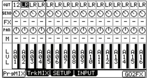
Each pad is assignable to a different output bus and effects bus, and can have its own level and pan settings.
Synth Programs
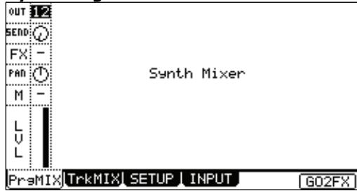
Since synth programs are assigned chromatically across the pads, each parameter is globally assigned.
Note: For more information about connecting to the external effects processor or mixer and about the operation of them, see the operation manual of these devices.
Program Mixer
The MPC5000 has 8 outputs (assignable mix out) as well as the stereo out. Entire tracks of a sequence can be sent out of these outputs. Additionally, Sample Programs can have their individual pads sent out of any one of these outputs individually, as a mono signal or a stereo pair. Here, we will discuss setting the outputs of a Sample Program's specific pads. This will allow you to send out individual pads to an external source, such as an effects processor, mixer, or a recording device.
Tip: Each track's settings can be viewed in detail by selecting the track and pressing [WINDOW].
Setting the Output
- In the MIXER mode, press [F1] (PrgMix).
The PrgMix page will be displayed.
Each column indicates pad 1 though 16 from the left and the currently selected pad is highlighted. The row at the top is the 'OUT' field, where you where you will assign a specific pad to a specific assignable output.
Note: Different pad banks can be selected by pressing the corresponding [PAD BANK] button.
- Hit the desired pad.
The column for the selected pad will now be highlighted.
- Select the desired output in the OUT row.
You can use the [CURSOR] buttons to move to each field in MIXER mode, and you can adjust each level with the [DATA] wheel. The following choices are available:
ST
The pad will be output to the stereo out.
1/2
The pad will be output stereo to [ASSIGNABLE MIX OUT] 1/2.
3/4
The pad will be output stereo to [ASSIGNABLE MIX OUT] 3/4.
5/6
The pad will be output stereo to [ASSIGNABLE MIX OUT] 5/6.
7/8
The pad will be output stereo to [ASSIGNABLE MIX OUT] 7/8.
1-8
The pad will be output in MONO to the corresponding [ASSIGNABLE MIX OUT] output.
Tip: You can also easily change the settings for tracks by using the Q-LINK controls. For more information on using the Q-LINK with MIXER Mode, see 'Using Q-LINK Controls with MIXER Mode' on page 81.
Setting the Level and Pan of a Pad
- Press the [MODE] button and then the [PAD 7] (MIXER).
- Press [F1] (PrgMix) to select the Pad Mix page.
In this display, each column indicates pad 1 though 16, starting from the left, and the currently selected pad is highlighted. The bar display on the bottom indicates the current level. Longer bars indicate higher levels.
Note: Different pad banks can be selected by pressing the corresponding [PAD BANK] button.
- Hit the desired pad.
The column of the selected pad will be highlighted. You can select several pads by hitting pads while holding in the [SHIFT] button. You can also select all pads in the PAD BANK by pressing a [PAD BANK] button while holding in the [SHIFT] button.
Tip: When you select several pads and change a parameter (Level or Pan), the parameter on each pad will be changed relatively with keeping the balance.
- Adjust the PAN value in the PAN row.
The fourth row down is labeled 'PAN'. Here is where the pan setting of individual pads are set. The knob graphic indicates the pan setting. The location of the line within the circle indicates the current pan setting.
- Adjust the Level value in the LVL row.
The bottom row is labeled 'LVL'. Here is where the level setting of individual pads is set. The dark line in each column represents the relative level of each pad, much like faders on a mixing board. You can use the [CURSOR] buttons to move to each field in MIXER mode, and you can adjust each level with the [DATA] wheel.
Tip: You can also easily change the settings for tracks by using the Q-LINK controls. For more information on using the Q-LINK with MIXER Mode, see 'Using Q-LINK Controls with MIXER Mode' on page 81.
■Assigning Effects to a Pad
With the MPC5000, you can route programs, or specific pads of Sample Programs to any of four (4) internal FX buses. To do this, you need to route the pad in the FX row. In this section, we will discuss routing specific pads to the FX buses.
Tip: This picture displays the signal flow of the sample sound to the stereo out through the effect section.
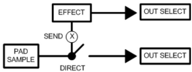
Note: Each FX bus can be assigned to a separate output, allowing for the dry signal and the affected signal to be routed independently. For more information, see page 146.
- In MIXER mode, press [F1] (PrgMix).
The PrgMix page will be displayed. Each column indicates pad 1 though 16 from the left to right, and the currently selected pad is highlighted.
Note: Different pad banks can be selected by pressing the corresponding [PAD BANK] button.
- Hit the desired pad.
The column of the selected pad will be highlighted.
- Select which FX Bus to send the pad to.
To adjust this value: simply move the cursor to the FX row, and use the [DATA] wheel.
OF
No effect will be used.
1 to 4
The effect bus number selected (1 to 4) will be used. The Pad sound will be sent to the selected effect section.
- Adjust the SEND level by selecting the control in the SEND row by turning the [DATA] wheel.
The display in the SEND row indicates the output setting. The graphical knob display in the FX row indicates the current send level. Increasing this level will increase the amount of effect for the selected pad.
Note: the SEND knob in the SEND row will be disabled if the selected FX bus has DIRECT OUT Disabled. For more information on DIRECT OUT, see page 134.
Muting Pads
Individual Pads can be muted. To mute a specific pad, do the following:
- In the MIXER mode, press [F1] (PrgMix).
The PrgMix page will be displayed.
Each column indicates pad 1 though 16 from the left and the currently selected pad is highlighted. The row at the top is the 'OUT' field, where you where you will assign a specific pad to a specific assignable output.
Note: Different pad banks can be selected by pressing the corresponding [PAD BANK] button.
- Hit the desired pad.
The column for the selected pad will now be highlighted.
- In the MUTE row (Displayed as 'M'), scroll with the [DATA] wheel to select one of the following.
一
Pad will play as normal
M
Pad is muted
Viewing Program Info
Each Program track can be selected and viewed in detail.
To view a track's details, select the desired track and press the [WINDOW] button.
Parameters such as Volume, Pan and Outputs can individually be edited here with greater detail.
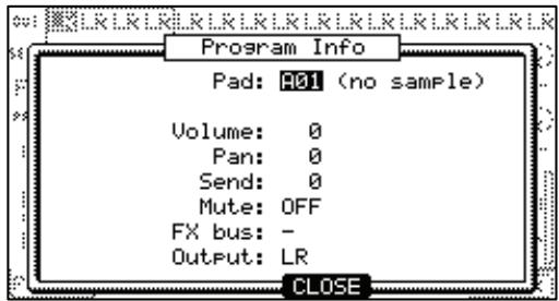
Track Mixer
In the TRACK MIXER tab, you can control the overall volume of the entire track, along with each of the other tracks. On the TRACK MIXER tab, it's possible to adjust the level of each of the 64 sequence tracks simultaneously.
Note: while in Track Mixer, the pads are used to select the corresponding tracks. In this mode, pads will not make sound or send MIDI.
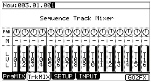
Setting the Level and Pan Position of a Track
- Press the [MODE] button and then the [PAD 7] (MIXER).
- Press [F2] (TrkMix) to select the Track Mix page.
In this display, each column indicates tracks 1 though 16, starting from the left, and the currently selected track is highlighted. The bar display on the bottom indicates the current level. Longer bars indicate higher levels.
Note: tracks 17-64 can be used by pressing the corresponding [PAD BANK] buttons.
03. Hit the pad corresponding to the desired track.
The column of the selected track will be highlighted. You can select several tracks by hitting pads while holding down the [SHIFT] button. You can also select all 16 tracks displayed by pressing a [PAD BANK] button while holding in the [SHIFT] button.
Tip: When you select several tracks and change a parameter (Level or Pan), the parameter on each track will be changed relative to the current setting.
04. Adjust the Level value in the LVL row.
The bottom row is labeled 'LVL'. Here is where the level setting of each track is set. The dark line in each column represents the relative level of each track, much like faders on a mixing board. You can use the [CURSOR] buttons to move to each field in MIXER mode, and you can adjust each level with the [DATA] wheel.
Tip: You can also easily change the settings for tracks by using the Q-LINK controls. For more information on using the Q-LINK with MIXER Mode, see 'Using Q-LINK Controls with MIXER Mode' on page 81.
05. Adjust the Pan value in the PAN row.
The row of knobs above the track level is labeled 'PAN'. Here is where the pan position of each track is set. The knob position in each column represents the relative pan position of each track, much like knobs on a mixing board. You can use the [CURSOR] buttons to move to each field in MIXER mode, and you can adjust each level with the [DATA] wheel.
Tip: You can also easily change the settings for tracks by using the Q-LINK controls. For more information on using the Q-LINK with MIXER Mode, see 'Using Q-LINK Controls with MIXER Mode' on page 81.
Muting a Track
Each track can be muted from MIXER mode. To mute a track, do the following:
- In the MIXER mode, press [F2] (TrkMix).
The TrkMix page will be displayed.
Each column indicates track 1 though 16 from the left and the currently selected track is highlighted. The row at the top is the 'OUT' field, where you where you will assign a specific track to a specific assignable output.
Note: tracks 17-64 can be used by pressing the corresponding [PAD BANK] buttons.
- Hit the pad corresponding to the desired track.
The column for the selected track will now be highlighted.
- In the MUTE row (Displayed as 'M'), scroll with the [DATA] wheel to select one of the following.
一
Track will play as normal
M
Track is muted
Using Q-LINK Controls with MIXER Mode
In addition to the [DATA] wheel, the Q-LINK controls can be used to change settings within MIXER mode. Tracks can be edited in groups of four. Which four are editable with Q-LINKS is determined by which pad is currently selected:
Pad 1-4 selected: QLINKS control Tracks 1-4
Pad 5-8 selected: QLINKS control Tracks 5-8
Pad 9-12 selected: QLINKS control Tracks 9-12
Pad 13-16 selected: QLINKS control Tracks 13-16
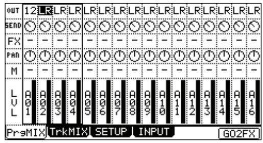
When in MIXER mode, the Q-LINK controls have the following functions:
Q-LINK Q9-12 AFTER BUTTONS
These buttons correspond to the OUT setting for the OUT row. Pressing this button repeatedly will toggle through each OUT setting for the selected column.
Q-LINK Q9-12 KNOBS
These knobs correspond to the FX SEND setting for the SEND row.
Q-LINK Q5-8 AFTER BUTTONS
These buttons correspond to the FX setting for the FX row. Pressing this button repeatedly will toggle through each FX bus for the selected column.
Q-LINK Q5-8 KNOBS
These knobs correspond to the PAN setting for the PAN row.
Q-LINK Q1-4 AFTER BUTTONS
These buttons correspond to the MUTE setting for the MUTE row. Pressing this button repeatedly will toggle the MUTE setting on or off. Holding the [SHIFT] button while pressing one of these buttons will solo the selected track.
Q-LINK Q1-4 SLIDERS
These sliders correspond to the LEVEL setting for the LVL row.
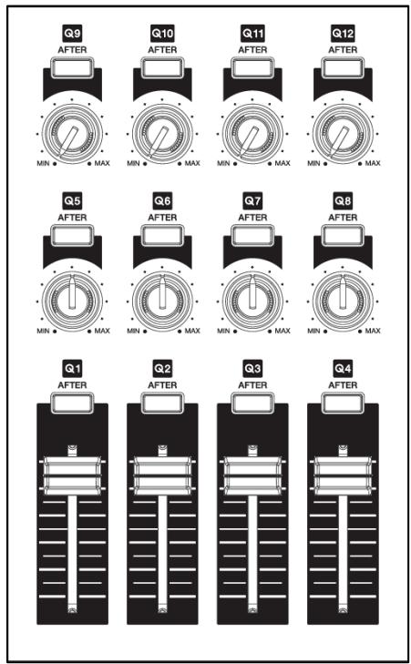
Viewing Track Details
Each Track can be selected and viewed in detail.
To view a track's details, select the desired track and press the [WINDOW] button.
Volume, Pan and Mute can individually be edited here with greater detail.
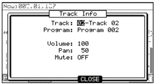
Mixer Automation
The MPC5000 can record information such as Level and Pan changes so that they will automate during sequence play back.
- In the MIXER mode, press the [F3] (SETUP) button.
The SETUP page will be displayed.
- In the 'Record mix changes:' field, select YES with the [DATA] wheel.
If you set this field to YES and change the LEVEL, SEND, MUTE, or PAN in the PrgMix page during the sequence is recording, the changed data will be recorded into the sequence. Track Mix levels will also be recorded. The sequence will be
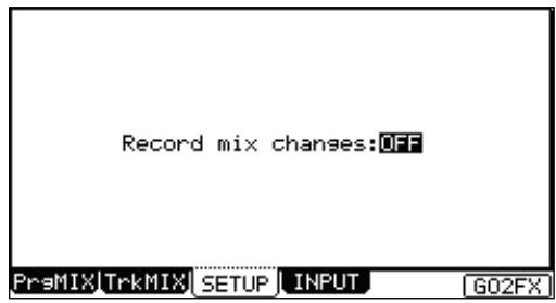
played with changing the Level or the Pan as you did during the recording. The mixing data recorded in the sequence is displayed in STEP EDIT page and you can edit it same as other MIDI event.
Note: Level event shares with Level of Q-LINK.
■ Shortcut between MIXER and EFFECTS mode.
While in MIXER mode, you can easily switch to EFFECTS mode by pressing [F6] (GO2FX).
While in EFFECTS mode, you can easily switch to MIXER mode by pressing [F5] (GO2MIX).
Tip: This is especially useful when searching for the right effect for the right sample.
Input Thru
The MPC5000 can mix the incoming signal from RECORD IN or S/PDIF IN with the play back sound from the MPC5000.
You can also route the Input Thru signal to one of the four effects busses, and you can control the level, pan, effects send, etc of incoming signal with the Q-LINK sliders and knobs.
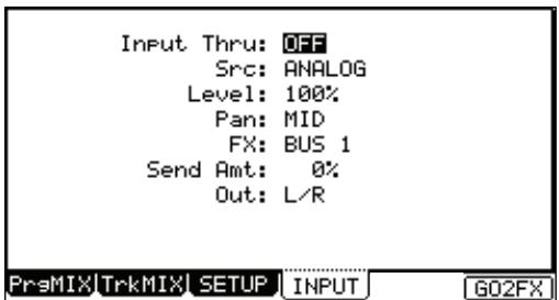
Applying effects to an incoming signal
Note: In this explanation, some Effect should be selected first. If you don't have any, select some Effects as described in the chapter entitled 'Effects' on page 133.
- Press the [INPUT THRU] button.
The INPUT page will be displayed.
You can also get to the INPUT page by pressing the [F4] (INPUT) button in MIXER mode.
-
In the 'Input thru' field, select ON.
-
Set the 'Src' field to ANALOG
You can also set DIGITAL here to be able to listen to digital S/PDIF sources.
- Set the 'level' field to an appropriate level
If you select ANALOG in the 'Source' field, adjust the [REC GAIN] volume with using the level meter in the RECORD mode in advance. If you select DIGITAL in the 'Source' field, the [REC GAIN] volume is not used.
-
Set 'Pan' as desired.
-
Set the 'FX' field to one of the four Effects Busses.
Be sure to select an Effects Buss which has effects assigned.
- Set the 'SendAmt' field to the desired level.
This controls how much signal from the Input Thru source is sent to the Effects Buss. For a wetter effects signal, turn this parameter up.
Note: if the selected Effects Buss has its 'Direct Out' set to off, this parameter is hidden.
- Set the 'Out' field to 'L/R'
You can also route the Input Thru source to one of the 8 individual outputs, in stereo pairs, or mono.
Chapter 11: Sampling
In this chapter, you will learn how to record from an analog external device (CD player's analog output, microphone, etc...) so that you can play that sound by hitting a pad.
Preparing the recording
- Connect the external device to [RECORD IN], which is located on the MPC5000's rear panel.
The MPC5000 can accept audio input from its 1/4 inch / MIC combo jacks, as well the RCA and Digital inputs. Any of these connections will work for recording.
Note: Make sure to set the [LINE/MIC] and [LINE/PHONO] switches appropriately for your source. Incorrect setting of this switch can produce distortion.
- Press the [MODE] button and then [PAD 4] (REC SAMPLE).
When you press the [MODE] button, its LED will blink. Pressing [PAD 4] with the [MODE] button's LED on displays the SAMPLE page, where you adjust the setting for the recording.
- Select the 'Input' field, and select the recording source. For this example, please select ANALOG.
The following sources are available as well:
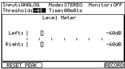
ANALOG
The MPC5000 will record the incoming signal from the RECORD IN on the rear panel.
PHONO
The MPC5000 will record through the PHONO inputs. This input is useful for devices with RCA-type connections.
DIGITAL
The MPC5000 will record the incoming signal from the DIGITAL IN on the rear panel.
MAIN OUT
The MPC5000 will record the same signal as the signal from the [STEREO OUT] on the rear panel.
OUT 1-2, 3-4, 5-6, 7-8
The MPC5000 will record the same signal as the signal from the selected [ASSIGNABLE MIX OUT].
INT CD
The MPC5000 will record the signal from Audio CD in internal CD drive. (This only can be selected if the optional CD drive is installed.)
- Select the 'Mode' field and select 'STEREO' or 'MONO'.
STEREO
The MPC5000 will record the left and right channel signals as a stereo sample.
MONOL
The MPC5000 will record only the left channel signal.
MONOR
The MPC5000 will record only the right channel signal.
- Play the source. Check the level meter on screen and adjust the recording level using the [REC GAIN] knob.
Note: When you select DIGITAL, MAIN OUT, one of the Assignable OUT pairs, or CD in the 'Input' field, you cannot adjust the recording level with the [REC GAIN] knob.
The level meter moves according to the input level. If the meter goes too far to the right, the sound will be distorted, but if the sound level is too low, the sample will gain a lot of noise. Set the level as high as possible without reaching the right edge (clip).
- Select the 'Threshold' field and set the threshold level to start the recording.
When the MPC5000 is in record enable mode, it starts the recording automatically when the level of the incoming source exceeds the threshold level. If you set the threshold level too high, the MPC5000 may not start the recording when you play the input source, or the beginning of the recording may be missing. If you set the threshold level too low, the MPC5000 may start the recording before you play the external source. Set this to the appropriate level using the level meter. The threshold level will be indicated as shown in the figure to the right.
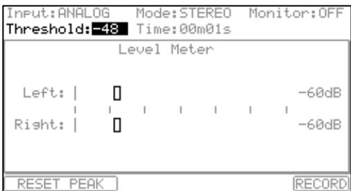
- Select the 'Time' field and set the recording time.
The MPC5000 will record for the time set in this field. We recommend you set the time a little longer than the actual recording time. You can finish the recording manually.
Starting the recording
- Press [F6] (RECORD) button.
The MPC5000 will be in the Record Ready mode, and the bottom of the screen will change as shown on the right.
This indicates that the MPC5000 is waiting for the incoming signal. It starts the recording when the input signal exceeds the threshold level.
Pressing the [F5] (CANCEL) button cancels the record ready mode and resets the MPC5000.
Pressing the [F6] (START) button starts the recording, even when the incoming signal does not exceed the threshold level.
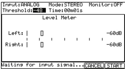
Note: If you press the [F6] (RECORD) button when the external source is higher than the threshold level, the MPC5000 will start the recording right after you press the [F6] (RECORD) button.
- Play the external source.
The MPC5000 will start the recording automatically when the level of the input signal exceeds the threshold level. During the recording, the bottom of the screen will change as shown on the right.
The MPC5000 stops the recording at the time set in the 'Time' field.
You can stop the recording manually before the time set in the 'Time' field, by pressing the [F6] (STOP) button. To cancel the recording, press the [F5] (CANCEL) button.
After the MPC5000 ends the recording, the Keep or Retry window will be displayed:
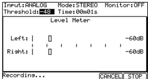
- Check the recorded sample by pressing [F4] (PLAY) button.
If you press the [F4] (PLAY) button, you can play back the recorded sample until you release the button.
If you do not like the recording, you can remove the recording and return to the SAMPLE page by pressing the [F2] (RETRY) button. If you like the recording and decide to keep it, proceed to the next step.
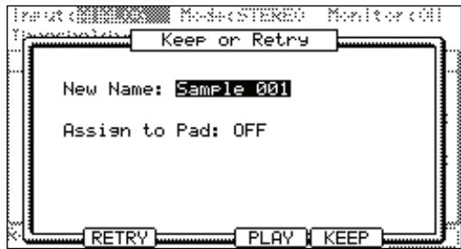
- Select the 'New name' field with the cursor, and set the name for the sample.
In the 'New name' field, the recorded sample will have a new name automatically. You can select the 'New name' field with the cursor and change the sample name if needed. For more information about setting the sample name, see the 'Setting Names' section on page 18.
- Select the Assign to 'Pad' field with the cursor and select the pad to which you wish to assign the sample.
You can select the pad directly by hitting the pad when the cursor is in the Assign to 'Pad' field. If you just wish to keep the recorded sample in the MPC5000's memory and not to assign to the pad, select OFF with the [DATA] wheel.
- Press the [F5] (KEEP) button.
This closes the Keep or Retry windows and goes back to the SAMPLE page.
Note: The recorded sample will be removed when you switch the unit off. To keep the sample, you need to save on a memory card or the internal Hard Disk. For more information on saving, see 'Saving and Loading (DISK Mode)' on page 149.
Sampling - detailed information
In this section, you will learn about several features regarding the recording which were not described in the previous section.
Recording the digital signal
Here, you will learn how to record a digital signal.
Note: You can record only from the devices whose sampling rates are set to either 44.1 kHz (ex. CD player) or 48 kHz (ex. DAT). The MPC5000 does not support the other sampling rates.
Preparing the recording
- Connect the external device to the DIGITAL IN which is located on the MPC5000's rear panel.
- Press the [MODE] button and then [PAD 4] (REC SAMPLE) to display the SAMPLE page.
- Select the 'Input' field and select DIGITAL.
- Select the 'Mode' field and select STEREO or MONO.
- Play the source. Check the level meter on screen.
Note: With the digital recording, you cannot adjust the recording level.
- Select the 'Threshold' field and set the threshold level to trigger the recording.
- Select the 'Time' field and set the recording time.
For the next steps, proceed as described in the 'Starting the recording' section on page 84.
Recording the MAIN OUT
In this section, you will learn how to record the same signal from the STEREO OUT of the MPC5000. With this feature, you can add the effects to the recorded sample and resample it, or you can record the phrase that you created with the sequence feature, as one sample.
Preparation For Recording
- Prepare the system so that you can play the desired sound by hitting the pads or playing back the sequence.
The sound that the MPC5000 will actually record is exactly the same as the sound from the [STEREO OUT]. Before going back to SAMPLE mode, set the program and sequence so that the desired sound will be output from the [STEREO OUT]. - Press the [MODE] button and then [PAD 4] (REC SAMPLE) to display the SAMPLE page.
- Select the 'Input' field and select MAIN OUT.
- Select the 'Mode' field and select STEREO or MONO.
- Select the 'Time' field and set the recording time.
Note: When the MAIN OUT is selected, the recording level is decided by the setting of Master level in OTHER mode. The initial setting of the Master level is -12dB as the output sound will not distort when many samples are played back simultaneously. If you record one sample through MAIN OUT with this setting, the recorded sample level is lower than the original sample level. In this case, if you set the Master level to 0dB, the recorded sample level is same as the original sample level.
For the next steps, proceed as described in the 'Starting the recording' section on page 84.
Recording the internal CD's sound
In this section, you will learn how to record the CD's sound from the internal CD drive directly to the MPC5000. (When the optional internal CD drive is installed.)
Preparation For Recording
- Set the audio CD you wish to record on the tray of the internal CD drive.
- Press the [MODE] button and then [PAD 4] (REC SAMPLE) to display the SAMPLE page
| Input:CD Mode:STEREO Monitor:ON Threshold: 0 Time:00m10s | ||
| CD Control | ||
| Left: | | | | | -60dB | ||
| Right: | | | -60dB | ||
| Track: 01 <STEP> <<BAR> STOP PLAY Time: 00m13s (03m28s - 13 tracks) | ||
| RESET PEAK | RECORD |
- In the 'Input' field, select CD.
The CD CONTROL page will be displayed, instead of LEVEL METER page. - In the 'Mode' field, select STEREO or MONO
- In the 'Time' field, set the recording time.
CD drive operation
Track
This shows the selected track number of audio CD.
Time
This shows the play time on track.
[PLAY START]
This key plays the Audio CD from the beginning of the track
[PLAY]
This key plays the Audio CD from the current time position.
[STEP]
This key will Rewind /Fast forward the Audio CD.
[BAR]
This key selects the track in Audio CD.
[STOP]
This key stops the Audio CD.
- Select the track you wish to record with the [BAR] buttons and then press the [PLAY] button.
- Press the [F6] (RECORD) button.
The MPC5000 will start the Audio CD recording. For the next steps, proceed as described in the 'Starting the recording' section on page 84.
Note: When CD is selected, you cannot adjust the recording level. You cannot start the recording by exceeding the threshold level. You must start the recording by pressing the [F6] (RECORD) button.
Hint: In the LOAD page, you can load a track from the audio CD into the internal memory. For more information, see 'Saving and Loading (DISK Mode)' on page 149.
Other Features
Monitoring feature
In the 'Monitor' field of the SAMPLE page, you can determine if you want to monitor the input signal (output the signal from the STEREO OUT) in SAMPLE mode or not.
ON
You can monitor the input signal. This is useful when you record sounds directly from the CD player.
OFF
You cannot monitor the input signal. For example: when you send the signal to the MPC5000 through a mixer, both the source sound and the monitored sound may be sent to the mixer. To avoid this, you should set this to OFF.
Peak hold/Reset peak feature
The level meter in the SAMPLE page has the peak hold feature. This is a useful feature for adjusting the signal level during recording. Normally, the display of the level meter changes in real time according to the level of the incoming signal. However, the peak hold displays the maximum level and keeps the level, even when the level decreases.
To reset the peak hold display, press the [F1] or [F2] (RESET PEAK) button in the SAMPLE page.
RECORD INFORMATION Window
Important information on your recording can be accessed while in REC SAMPLE Mode via the RECORD INFORMATION Window. To access the RECORD INFORMATION Window, press the [WINDOW] button while in REC SAMPLE Mode.
The following information and parameters can be accessed here.
Pre Record Time
To avoid clicks / pops or errors when recording, the MPC5000 can cache the beginning of the recording. When the recording starts, the cache is added to the beginning of the sample.
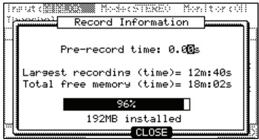
For example, if you are recording from CD, and you press the (F6) [RECORD] button to start recording at 3 minutes, sample will contain data starting from 2:59. This parameter will allow for up to one second of recording time to be cached. This is great for sampling "on the fly" to make sure the beginning of, for example, a bass hit isn't cut off when recording live.
Largest recording (time)
This shows the largest amount of time a single recording can be. This is especially useful when the 192MB expansion is installed. The EXM-E3 adds a second chunk of 128MB of sample recording time, which totals 192 when combined with the built in RAM. This allows a sample totaling 128MB in size, or over 24 minutes of mono sampling time for a single sample.
Total free memory (time)
This field displays how much recording time is left in RAM. This will also tell you how much RAM is installed in your unit.
Direct Recording feature
Recording a live performance while listening to a sequence
Preparing the recording
- Connect the external device to the RECORD IN, which is located on the MPC5000's rear panel.
- Press the [MODE] button and then [PAD 4] (REC SAMPLE).
- Select the 'Input' field, and then select the recording source.
ANALOG
The MPC5000 will record the incoming signal from the RECORD IN on the rear panel.
DIGITAL
The MPC5000 will record the incoming signal from the DIGITAL IN on the rear panel.
In Direct Recording, the MAIN OUT/CD are not available. For this example, please select ANALOG.
- In the 'Mode' field, select STEREO or MONO.
- In the 'Monitor' field, select 'ON'.
If you set the Monitor' field to 'ON', you can hear your performance from the OUTPUT of the MPC5000.
- Play your instrument and check the level meter. You can adjust the recording level using the [REC GAIN] knob.
Note: When you select DIGITAL in the 'Input' field, you cannot adjust the recording level with the [REC GAIN] knob. The level meter moves according to the input level. If the meter goes too far to the right, the sound will be distorted, but if the sound level is too low, the sample will gain a lot of noise. Set the level as high as possible without reaching the right edge (clip)
Note: In Direct recording, the threshold / 'Time' fields are not available.
Note: In Direct recording, the MPC5000 keeps recording to the maximum time of the free memory and stops the recording when you press the [STOP] button. Setting the 'Time' fields will have no effect.
The Direct Recording feature will allow you to record a signal from 'RECORD IN' while the sequence is playing back. This makes it much easier to ensure the sample you record will match the Tempo of the sequence.
Because a sample by Direct Recording is recorded to the internal RAM memory, the recording time is dependent upon the internal memory capacity.
Starting the recording
Tip: The recorded sample will be assigned to the pad in the Program which is currently selected in the MAIN page. It will be useful to make an empty Program to assign the recorded sample to before attempting a Direct Recording.
- Press [MAIN] button.
The Main page will be displayed.
- In the 'Type:' field, press [WINDOW] button.
The Direct Recording window will be displayed. If you press the [F5] (Turn ON) button, the window will be closed and the MAIN page will be displayed with waiting for the Direct Recording.
If you press the [F4] (CANCEL), the window will be closed and the MAIN page will be displayed.
-
Select [F5] (Turn ON).
-
The MAIN page is displayed and the 'Type:' field becomes 'Direct Recording'.
The MPC5000 is now in stand-by mode for Direct Recording. You can start the sequence freely in stand-by mode for Direct Recording.
[F6] (RECORD)
The MPC5000 will start the recording.
[F5] (CANCEL)
The MPC5000 will go back to the ordinary MAIN page.
[F2] (CLICK)
![AKAI MPC5000 - [F2] (CLICK) - 1](/content/2025/01/152537/images/a0166e9460019a54f79fb92eaa0f875c567f29d3c30c5696416e8c8aca0f95e3.jpg)
![AKAI MPC5000 - [F2] (CLICK) - 2](/content/2025/01/152537/images/e8dd4b5cd6e77e3aadee272e6db7915b1e009f101552d4202097fb5f24e6f73b.jpg)
The MPC5000 will go to the 'Click/Metronome' page. For more information, see the section entitled 'Click/Metronome' on page 25.
Note: In Direct Recording mode, you cannot change the Sequence, Track, or Track type. If you want to change them, press [F5] (CANCEL) and go back to the MAIN page.
- Press the [PLAY] or [PLAY START] button for playing the sequence.
- Press the [F6] (RECORD) button when you wish to start the recording and play your performance.
The MPC5000 will start the recording and the bottom of MAIN page will be changed as shown:
![AKAI MPC5000 - [F2] (CLICK) - 3](/content/2025/01/152537/images/0c6aaf2f75e02b2c3060cb8eabb614d617aef4f16eacc896757d3cf439e047aa.jpg)
You can stop the recording by pressing [F6] (STOP) button. If you want to cancel the recording, press [F5] (CANCEL).
Tip: When you use Direct Recording, the foot switch is very useful for starting/stopping the sequence, leaving your hands free. For more information on this, see 'Using the Footswitches' on page 176.
After finishing the recording, the Keep or Retry window will be displayed.
Note: In Direct Recording, the MPC5000 will keep the recording by pressing the [F6] (STOP), whether the sequence is set to LOOP ON or OFF.
- Check the recorded sample by pressing [F4] (PLAY) button.
If you press the [F4] (PLAY) button, you can hear the recorded sample until you release the button. If you do not like the recording, you can delete the recording and return to the SAMPLE page by pressing the [F2] (RETRY) button. If you like the recording and decide to keep it, proceed to the next step.
- In the 'New name' field, the recorded sample will have a new name automatically.
If you wish to enter in a new name, use the [CURSOR] buttons and the [DATA] wheel to enter in the new name.
For more information about entering in a sample name, see the 'Setting Names section on page 18.
- Select the 'Assign to Pad' field with the cursor and select the Pad to which you wish to assign the sample by hitting the Pad.
If you just wish to keep the recorded sample in the MPC5000's memory and not assign it to the Pad, select OFF with the [DATA] wheel.
In the Keep or Retry window in Direct Recording mode, if you select the pad in the 'Assign to pad' field, the new 'Record event' field will be displayed. If you select YES in the 'Record event' field, the recording start timing is written as track events in the sequence. The recorded sample can be played back with the same timing that the sequence is playing back. For this example, select 'YES'.
- Press the [F5] (KEEP) button.
This c t t. You will hear the recorded sample is in the same timing as the sequence.
Chapter 12: Sample Editing
Setting the Start / End Points
The start/end points set the part of the sample data which will be played. The recorded sample may - for example - have silence at the beginning, which may make it more difficult to place the sound in the correct spot when hitting the pad. You can fix this by adjusting the start point. You can also adjust both the start and end points to play only a part of the phrase. If the sample has extra silence or unwanted sound at the end, you can delete the empty parts by adjusting the end point and using the edit feature. This is a good way to free up additional memory.
Start/end points are displayed in sample points. The sample point is the minimum unit used for sample editing. The MPC5000 has 44,100 sample points per second.
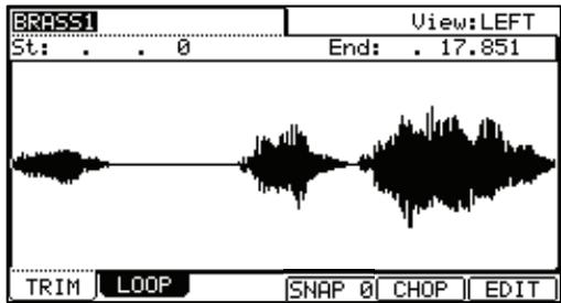
About the waveform display
The TRIM page displays the waveform of the sample selected in the 'Sample' field. It displays the waveform of the whole sample, with the parts set by start/end points highlighted.
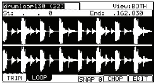
LEFT / RIGHT / BOTH Waveform View
If you select a stereo sample, you can select the channel (LEFT/RIGHT or BOTH) to display in the 'View' field.
Adjusting the start point
- Press [MODE] and [PAD 5] (TRIM).
When you press the [MODE] button, its LED will blink. Pressing [PAD 5] while the [MODE] button's LED is blinking will display the TRIM page.
- Select the 'Sample' field and select a sample you wish to edit.
The 'Sample' field is located in the upper left corner of the screen, which displays the sample name. This field chooses which sample's waveform is to be displayed.
- Select the 'St' (start) field and adjust the start point.
You can change the start point value by turning the [DATA] wheel. If you press the left or right [CURSOR] buttons while holding [SHIFT], you can move the cursor to higher points within the numeric display to allow for quicker value selection. You can also enter the value directly with the numeric keypad.
Additionally, the start point can be edited by moving the [Q1] Q-LINK slider.
- Hit the pad to check the start point.
When you hit the pad, the MPC5000 plays the sample. The playback method varies depending on the pad.
[PAD 13] (PLAY LOOP)
The MPC5000 will play the sample from the loop point to the end point repeatedly.
[PAD 14] (PLAY TO)
The MPC5000 will play the part before the loop point.
[PAD 15] (PLAY FROM)
The MPC5000 will play the sample from the loop point.
[PAD 16] (PLAY ALL)
The MPC5000 will play the whole sample.
[PAD 1] to [PAD 12]
The MPC5000 will first play from the start point to the end point, and then play from the loop point to the end point repeatedly.
Adjusting the end point
- Select the 'End' field to adjust the end point.
You can change the end point value by turning the [DATA] wheel. If you press the left or right [CURSOR] buttons while holding [SHIFT], you can move the cursor to higher points within the numeric display to allow for quicker value selection. You can also enter the value directly with the numeric keypad.
Additionally, the end point can be edited by moving the [Q1] Q-LINK slider.
- Hit the pad to check the end point.
When you hit the pad, the MPC5000 plays the sample. The playback method varies depending on the pad.
[PAD 13] (PLAY LOOP)
The MPC5000 will play the sample from the loop point to the end point repeatedly.
[PAD 14] (PLAY TO)
The MPC5000 will play the part before the loop point.
[PAD 15] (PLAY FROM)
The MPC5000 will play the sample from the loop point.
[PAD 16] (PLAY ALL)
The MPC5000 will play the whole sample.
[PAD 1] to [PAD 12]
The MPC5000 will first play from the start point to the end point, and then play from the loop point to the end point repeatedly.
■ Snapping to the Next Zero Crossing (SNAP 0)
For easier sample editing, the MPC5000 can snap the start or endpoint of a sample to the next zero crossing. To do this, do the following:
- press F2 while in TRIM Mode.
- Select the start or endpoint of the current sample.
- press the F4 button.
The selected point will snap to the next zero crossing.
Zooming in/out
With the Fine window, you can zoom in to a part of the waveform and edit the part in detail. Place the cursor in either in the 'St' (Start) or 'End' field, and press the [WINDOW] button. The Fine window will be displayed.
In the Fine window, the waveform display varies depending on the location of the cursor. When you select the 'St' (Start) field with the cursor, it displays the start point in the center of the window. When you select the 'End' field, it displays the end point in the center.
If you press the [F2] (ZOOM-) button the waveform will be zoomed out, if you press the [F3] (ZOOM+) button, it will be zoomed in.
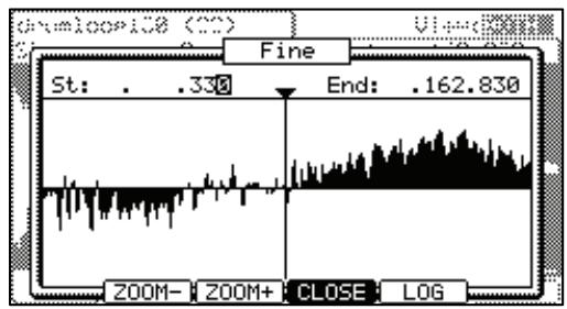
LINEAR and LOGARITHMIC displays
The vertical axis indicates the sample's level. Normally, the waveform display is set to LINEAR, which displays the sample level as it is. However, some parts (fade out part etc...) may not be displayed in the waveform if the level is too low. In this case, you can switch to the LOG (logarithmic) display by pressing the [F5] (LOG) button and you can see the parts whose level is low. When you switch to the LOG mode, the display in the [F5] button will change to LINEAR. To switch back to the LINEAR mode, press the [F5] button again.
Adjusting the TRIM and LOOP Points at the Same Time (LOCK)
The selection on the Trim and LOOP pages can be linked. This will allow adjustments on one page to be reflected on the other for easier editing.
To link TRIM and LOOP selection points, select the LOCK icon as shown on the right, and turn the [DATA] wheel. This will change the icon from unlocked to locked, indicating that TRIM and LOOP endpoints are now locked.
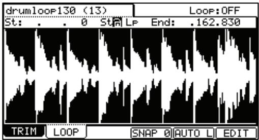
Deleting Unused Parts from a Sample (DISCARD)
The MPC5000 plays back only the part of the sample from the start point to the end point. The parts outside these points are not used for the playback. With the Discard function, you can delete these unnecessary parts to save memory.
Tips: If you do not like the results of your sample edit, the edit can be undone by pressing the [UNDO] button. To redo the change, press the [UNDO] button again.
- Adjust the start/end points.
Set the points so that the MPC5000 plays back only the necessary part. - Press [F6] (EDIT).
The Sample Edit window will be displayed. - In the 'Edit' field, select DISCARD.
- Press [F5] (DO IT).
The data outside the start/end points will be deleted. The deleted data will be returned to the available memory.
Deleting a Section of a Sample (DELETE)
The Delete function will remove the section between the Start and End points. The parts of the sample outside of the Start / End points will be joined with no gap between them.
Tips: If you do not like the results of your sample edit, the edit can be undone by pressing the [UNDO] button. To redo the change, press the [UNDO] button again.
- Adjust the start/end points.
Set the range that you wish to delete with the start/end points. - Press the [F6] (EDIT) button.
The Sample Edit window will be displayed. - In the 'Edit' field, select DELETE.
- Press the [F5] (DO IT) button
The section between the start and end points will be deleted with no gap between.
Silencing Part of a Sample (SILENCE)
The Silence function will remove the section between the Start and End points, leaving silence in its place.
Tips: If you do not like the results of your sample edit, the edit can be undone by pressing the [UNDO] button. To redo the change, press the [UNDO] button again.
- Adjust the start/end points.
Set the range you wish to silence with the start/ end point. - Press [F6] (EDIT).
The Sample Edit window will be displayed. - In the 'Edit' field, select SILENCE.
- Press [F5] (DO IT)
The section between the start and end points will be deleted, and a section of silence equal in length to the selection will be put in its place.
Saving part of a sample as a new sample (EXTRACT)
You can extract the part of the sample set with the Start/ End points, as a new sample. For example, you can extract the snare sounds from the recorded drum loop and save it as a new sample to use it separately.
- Adjust the start/end points.
Set the desired part with the start and end points. - Press the [F6] (EDIT) button.
The Sample Edit window will be displayed. -
In the 'Edit' field, select EXTRACT.
-
In the 'New name' field, set the name for the new sample.
- Press the [F5] (DO IT) button.
The part between the start/end points will be saved as a new sample.
Converting a Stereo Sample to Mono (STEREO TO MONO)
This function will convert the current sample to a new mono sample.
- In the 'Sample' field, select the sample you wish to convert.
- Press [F6] (EDIT).
The Sample Edit window will be displayed.
- In the 'Edit' field, select STEREO TO MONO.
- Select how you want the file converted.
The following options are available:
Left
The Conversion will only use the left channel for conversion.
Right
The Conversion will only use the right channel for conversion.
Sum
The conversion will combine the left and right audio channels to a single mono channel.
- In the 'New name' field, set the name for the new sample.
- Press [F5] (DO IT).
The current sample will be copied to a new sample, and converted to MONO. It may take some time to process depending on the length of the sample.
Sample window features
Pressing the [WINDOW] button in the 'Sample' field bring up the Sample window. In the Sample window, you can make several settings for the selected sample.
Changing the sample name
- In the 'Sample' field in the TRIM page, select a sample that you wish to change the name of.
- Press the [WINDOW] button.
The Sample window will open.
- In the 'Sample name' field, enter the new name.
For more information for setting the name, see the 'Setting Names' section on Page 18. - Press [F4] (CLOSE) button.
It closes the window and goes back to TRIM page.
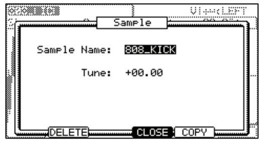
Changing the pitch of a sample
In the 'Tune' field, you can set the sample's pitch. The 2 digits in the left is semitones, the 2 digits in the right is cents (100 cents = 1 semitone). You can change the pitch in the PROGRAM mode as well.
The changes you made in the Sample window will be applied to the actual sample. So if you assign one sample to several pads, or use one sample in several programs, the change will be applied to all of them. To change the sample of a specific pad, use the PROGRAM mode.
■ Copying a sample
You can copy a sample and create a new sample.
- In the 'Sample' field in TRIM mode, select a sample to copy.
- Press [WINDOW].
The Sample window will be displayed.
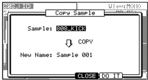
- Press [F5] (COPY).
The Copy Sample window will be displayed.
In the 'New name' field, set the name to the newly created sample.
For more information for setting the name, see the 'Setting Names' section on Page 18.
- Press [F5] (DO IT).
The MPC5000 will start copying the sample. To cancel the operation, press [F4] (CANCEL) instead.
- Deleting a sample
You can remove a sample from the memory of the MPC5000.
- In the 'Sample' field in TRIM mode, select a sample to delete.
- Press [WINDOW].
The Sample window will be displayed.
- Press [F2] (DELETE).
The Delete Sample window will be displayed.
- Press [F5] (DO IT).
This deletes the sample you have selected.
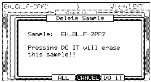
- Deleting all samples
You can delete all the sample data in the memory at one time.
- In the TRIM page, select the 'Sample' field and press [WINDOW].
The Sample window will be displayed.
- Press [F2] (DELETE).
The Delete Sample window will be displayed.
- Press [F3] (ALL).
The Delete ALL Samples window will be displayed.
- Press [F5] (DO IT).
This deletes all the samples from the MPC5000's memory.
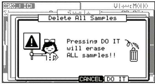
Other editing functions
NORMALIZE
When you assign a sample recorded at low level, its playback level will also be low. You can set the levels of pads in the MIXER mode, but you have to set some pads to a lower level. With the normalize function you can increase the sample level to the highest level possible without being distorted.
Tips: If you do not like the results of your sample edit, the edit can be undone by pressing the [UNDO] button. To redo the change, press the [UNDO] button again.
- In the 'Sample' field, select the sample you wish to normalize.
- Press [F6] (EDIT).
The Sample Edit window will be displayed.
- In the 'Edit' field, select NORMALIZE.
- Press [F5] (DO IT).
Normalizing will start. It may take some time to process depending on the length of the sample.
REVERSE
This function allows you to reverse the selected sample.
Tips: If you do not like the results of your sample edit, the edit can be undone by pressing the [UNDO] button. To redo the change, press the [UNDO] button again.
- In the 'Sample' field, select the sample you wish to reverse.
- Press [F6] (EDIT).
The Sample Edit window will be displayed.
- In the 'Edit' field, select REVERSE.
- Press [F5] (DO IT).
The MPC5000 will begin processing the sample. It may take some time to process depending on the length of the sample.
TIME STRETCH
With the Time Stretch function, you can lengthen or shorten the selected sample without changing the pitch. This is useful when you want to match one sample to another which has different tempo.
- In the 'Sample' field, select the sample you wish to TIME STRECH.
- Press [F6] (EDIT).
The Sample Edit window will be displayed.
- In the 'Edit' field, select TIMESTRETCH.
- In the 'Original tempo' field, set the sample's original tempo.
By default, the tempo of the selected Sequence is displayed. If you do not know the tempo of the selected sample, you can use the DETECT TEMPO page to find out the tempo.
Using the DETECT TEMPO
I. Set the start point and the end point of the sample to match the length of one bar at 4/4.
II. In the Sample Edit window, press [F2] (TEMPO).
III. Press the [F5] (DO IT) button.
The window will go back to the Sample Edit window and the calculated tempo in the DETECT TEMPO will be set automatically in the 'Original tempo' field.
Note: Depending on the sample, the DETECT TEMPO may not be able to accurately detect the correct tempo.
- In the 'New' field, set the desired new tempo.
Tip: If you want to change the sample length with %, you can use the following method. For example, if you wish to lengthen the sample by 20%, you set the original tempo to 100, then set the new tempo to 120. Now you can get the 20% longer sample.
- Set the 'Preset' field and 'Adjust' fields if necessary.
Preset:
The MPC5000 uses 18 preset algorithms to carry out the timestretch process, so you can select a preset that nearest resembles your sample's content. If the results are not to your liking, try experimenting with different presets. Each preset is divided into A, B or C:
A: Standard quality timestretch with fast processing.
B: Better quality timestretch with slower processing.
C: Highest quality timestretch with even slower processing.
Time stretch Presets:
- FEM VOX (Female Voice)
- MALE VOX (Male Voice)
- LOW MALE VOX (Low Male Voice)
- VOCAL
- HFREQ RHYTHM (High Frequency Rhythm Section)
- MFREQ RHYTHM (Middle Frequency Rhythm Section)
- LFREQ RHYTHM (Low Frequency Rhythm Section)
- PERCUSSION
- LFREQ PERC. (Low Frequency Percussion)
- STACCATO
- LFREQ SLOW (Low Frequency Slow Music)
- MUSIC 1
- MUSIC 2
- MUSIC 3
- SOFT PERC. (Soft Percussion)
- HFREQ ORCH. (High Frequency Orchestra)
- LFREQ ORCH. (Low Frequency Orchestra)
- SLOW ORCH. (Slow Orchestra)
Adjust
You can use this to 'tweak' the selected preset. If your selected preset is close to what you're looking for, but still needs a little fine tuning, try a few different settings here until you get the best result. A (+) value will help improve high frequency and percussive sounds while a (-) value will help improve bass sound. Most of the time, this can be left at zero.
- Press [F5] (DO IT).
It may take some time to process depending on the length of the sample.
The Keep or Retry window will be displayed after executing the timestretch.
'New Sample' field
Set the name for the new sample
[F2] (PLAY)
Auditions the new sample.
![AKAI MPC5000 - [F2] (PLAY) - 1](/content/2025/01/152537/images/f310a1885677e3ba190e8c9d01b87f9c12ebbdc9cbc5b784dee74ea93a7435e1.jpg)
[F3] (OVER W)
Deletes the original sample and keep the new sample by pressing this button. The sample name remains.
[F4] (RETRY)
This will return to the Sample Edit window without keeping the new sample.
[F5] (KEEP)
Allows you to save the new sample. You can also name the sample in the 'New Sample' field.
PITCH SHIFT (Changing the pitch of the sample)
With the Pitch Shift function, you can change the pitch of the selected sample without changing the length. This is useful when you want to change the pitch of the phrase sample in the sequence without changing the tempo.
- In the 'Sample' field, select the sample you wish to PITCH SHIFT.
- Press [F6] (EDIT).
The Sample Edit window will be displayed.
- In the 'Edit' field, select PITCH SHIFT.
- In the 'Pitch' field, set the pitch amount you wish to change.. Pitch: -12.00 - +12.00
This determines the amount of the pitch shift in semi tone and cent step. For example, if you enter +1.00 , the sample will pitch up one semi tone. If you enter +12.00 , the sample will pitch up one octave.
- Set the 'Preset' field and 'Adjust' fields if necessary.
Preset
The MPC5000 uses 18 preset algorithms to carry out the pitch shift process, so you should select a preset that closely resembles your sample's content. If you are not happy with the results, try experimenting with different presets.
A: Standard quality pitch shift with fast processing.
B: Better quality pitch shift with slower processing.
C: Highest quality pitch shift with even slower processing.
Time stretch Presets:
- FEM VOX (Female Voice)
- MALE VOX (Male Voice)
- LOW MALE VOX (Low Male Voice)
- VOCAL
- HFREQ RHYTHM (High Frequency Rhythm Section)
- MFREQ RHYTHM (Middle Frequency Rhythm Section)
- LFREQ RHYTHM (Low Frequency Rhythm Section)
- PERCUSSION
- LFREQ PERC. (Low Frequency Percussion)
- STACCATO
- LFREQ SLOW (Low Frequency Slow Music)
- MUSIC 1
- MUSIC 2
- MUSIC 3
- SOFT PERC. (Soft Percussion)
- HFREQ ORCH. (High Frequency Orchestra)
- LFREQ ORCH. (Low Frequency Orchestra)
- SLOW ORCH. (Slow Orchestra)
Adjust
You can use this to 'tweak' the selected preset. If your selected preset is close to what you're looking for, but still needs a little fine tuning, try a few different settings here until you get the best result. A (+) value will help improve high frequency and percussive sounds while a (-) value will help improve bass sound. Most of the time, this can be left at zero.
- Press [F5] (DO IT).
The Keep or Retry window will be displayed after executing the Pitch shift.
Lengthy samples will take longer to process.
'New name' field:
Enters the new name for the sample.
[F2] (PLAY)
Auditions the new sample.
![AKAI MPC5000 - [F2] (PLAY) - 1](/content/2025/01/152537/images/b8ce2e5574667053237d5ec42dcf1c97d730ee3e1dd76dcfa5678349b8769194.jpg)
[F3] (OVER W)
Deletes the original sample and keep the new sample.
[F4] (RETRY)
Returns to the Sample Edit window without keeping the new sample.
[F5] (KEEP)
Keeps the new sample with the name set in the New Name' field.
Dividing a Phrase Sample into Several Regions
Chop Shop
The Chop Shop function will allow you to divide a phrase sample into several regions. The MPC5000 has two different ways to use the Chop Shop function. 'AUTO', which divides a sample into several regions, automatically detecting the attack part of the phrase in the sample, and 'EQUALLY' which divides a sample to several regions of equal length.
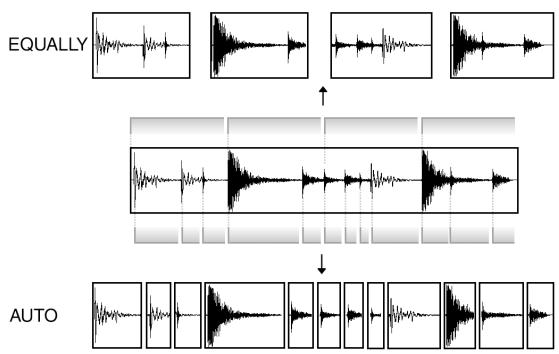
SLICED SAMPLE/PATCHED PHRASE
The divided sample, whether 'AUTO' or 'EQUALLY', can be used the following two ways. 'SLICED SAMPLES' will assign each divided region to a pad, or as a 'PATCHED PHRASE', which is one sample
which has the divided regions and the sequence data for playing the divided regions in time. You can change the tempo freely when playing the sequence.
Note: Chop Shop works on both stereo and mono files.
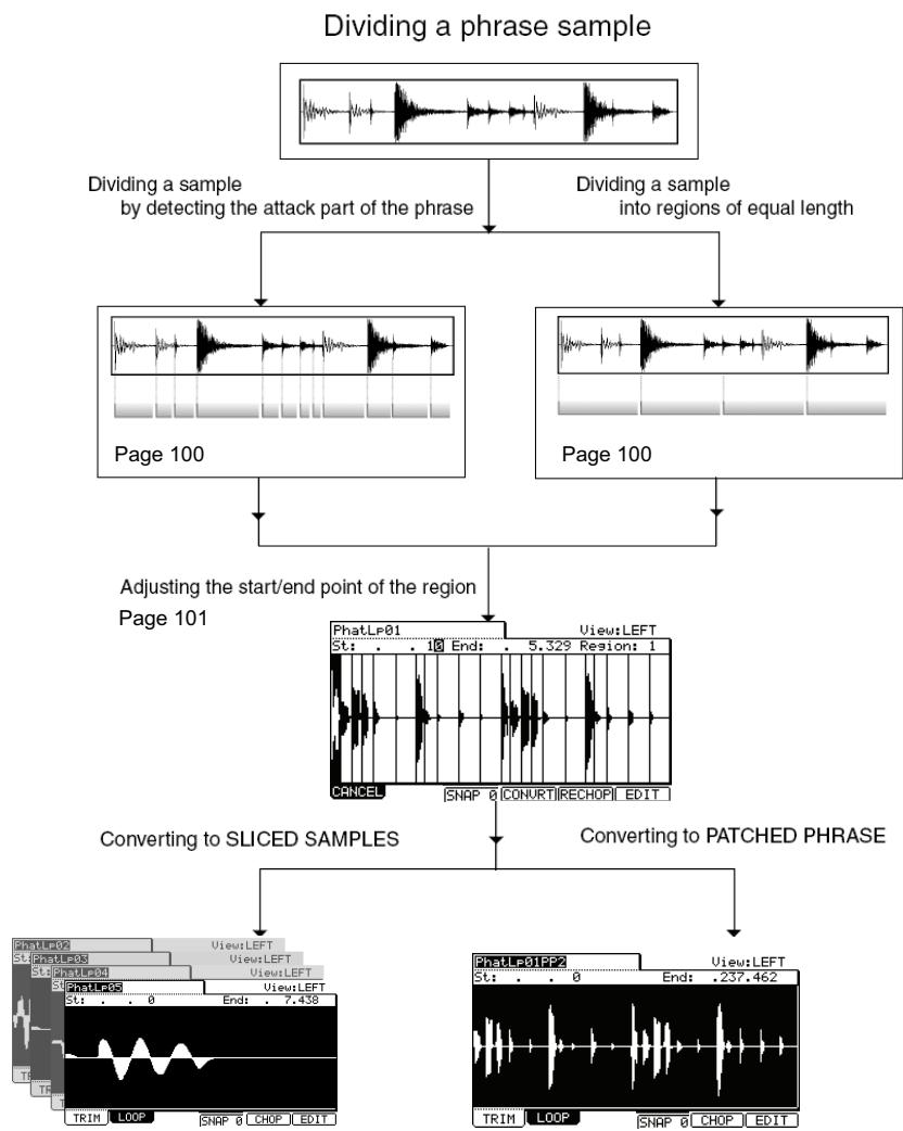
Page 101
Page 102
Dividing a Sample Automatically (AUTO)
- In the 'Sample' field within the TRIM page, select the sample you wish to edit.
You can set the sample range of your edit by adjusting the start/end points. For more information about adjusting the start/end points, see 'Setting the Start / End Points' on page 89.
- Press [F5] (CHOP).
The Chop Shop window will be displayed.
- In the 'Mode' field, select 'AUTO'.
Recovery time (0 - 100):
This sets the minimum time between the attack and the next attack. If you set this time too long, continuous attacks may not be detected. Select a smaller value when the sample has a lot of attack parts.
Threshold (0 - 100):
This sets the detectable level of an attack. The smaller the value, the more sensitive the detection will be, so if you select a very low value, everything will 'register' as an attack.
Sensitivity (0 - 100):
This sets the sensitivity used while detecting an attack. Selecting a smaller value will make the detecting process more sensitive towards varying attack levels.
- Press [F5] (DO IT).
The MPC5000 will start dividing the sample, then go to the 'Chop Shop' page. The MPC5000 divides a sample into several regions by automatically detecting the attack part of the phrase.
The next step is to adjust the divided regions.
Go to the 'Adjusting the Start / End Point of the Region' section for more information.
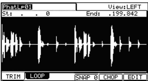
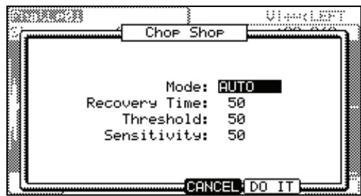
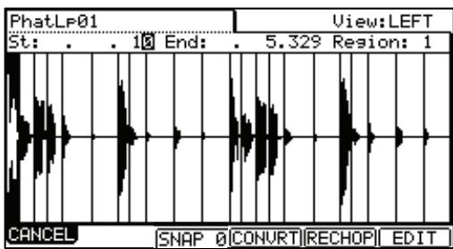
Dividing a Sample into Regions of Equal Length (EQUALLY)
- In the 'Sample' field within the TRIM page, select a sample you wish to edit.
You can set the sample range you wish to edit by adjusting the start/ end point.
For more information about adjusting the start/end points, see 'Setting the Start / End Points' on page 89.
- Press the [F5] (CHOP) button.
The Chop Shop window will be displayed.
- In the 'Mode' field, select 'EQUALLY'.
Number of Region
Set the number of regions you wish to divide the sample into. Usually, sixteen is a good start for a single measure loop.
- Press the [F5] (DO IT).
The MPC5000 will start dividing the sample, and then go to the 'Chop Shop' page. The MPC5000 will divide a sample into separate regions of equal length
The next step is to adjust the divided regions.
Go to the 'Adjusting the Start/ End Point of the Region' section for more information.
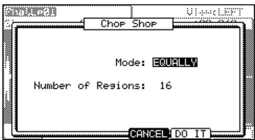
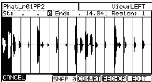
Adjusting the Start / End Point of the Region
A Region is each part of a sample that is divided with the 'AUTO' or 'EQUALLY' feature. You can adjust the start/end point of each region within the CHOP SHOP Page.
- After dividing a sample using the 'AUTO' or 'EQUALLY' function, the CHOP SHOP Page will be displayed.
In the CHOP SHOP Page, hitting Pad 1-12 will trigger the selected region.
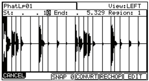
Tip: If you want to retry dividing a sample, press the [F5] (RECHOP) button. The 'Chop Shop' window will be displayed and you can set it again. If you want to stop the 'Chop Shop' feature, press the [F1] (CANCEL) button. The display will go back to the 'TRIM' page.
- In the 'Region' field, select the region number you wish to adjust the start/end point.
In the image above, region 1 is selected.
- In the 'St' field, adjust the start point of the region.
You can change the start point by using the numeric keys directly or by turning the [DATA] wheel button. If you press the left/right cursor key while holding the [SHIFT] button, you can select individual digits to change with the [DATA] wheel.
Note: Each start point of a region is same as the end point of the previous region. If you change the start point of a region, the end point of the previous region will be changed automatically.
- In the 'End' field, adjust the end point of the region.
You can change the end point the same way as the start point.
Note: Each end point of a region is same as the start point of the next region. If you change the end point of a region, the start point of the next region will be changed automatically.
If you press the [F6] (EDIT) button, the Region Edit window will be displayed. You can extract, divide, or combine regions in this page. Refer to 'Editing a Patched Phrase'.
If you wish to cancel the Chop Shop function, press the [F1] (CANCEL) button. The TRIM page will be displayed.
Converting Divided Samples to SLICED SAMPLES
- After adjusting the parameters within each region, press the [F4] (CONVRT) button.
The Convert window will be displayed. Here you can select two different ways for converting the divided sample, SLICED SAMPLE or PATCHED PHRASE
- In the 'Convert to' field, select SLICED SAMPLES.
Release
This sets the length that is added to the release after dividing a sample. If you set this to larger value, the release of the divided sample will be long and the sample data will be larger in size as well.
Create New Program
If you set this to YES, the MPC5000 makes a Program where each region is assigned to pads, from PAD A01 - A16, in order.
- After adjusting each parameter, press [F5] (DO IT).
The MPC5000 will process the SLICED SAMPLES and then the 'TRIM' page, with the divided sample, will be displayed.
The new sample name of the divided sample will be the original sample name and a number.
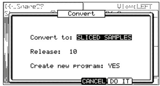
For Example:
Sample01 >
Sample01-01
Sample01-02
Sample01-03
Converting PATCHED PHRASE
- After adjusting the parameters within each region in the CHOP SHOP Page, press the [F4] (CONVRT) button. The Convert window will be displayed.
- In the 'Convert to' field, select PACHED PHASE
Release:
This sets the length that is added to the release after dividing a sample. If you set this to larger value, the release of the divided sample will be long and the sample data will be larger in size as well.
Original Tempo (30.0 - 300.0):
This sets the original tempo for the patched phrase. In the 'Original tempo' field, the automatically calculated original tempo is already displayed. If you know the original tempo of the sample, you should enter it.
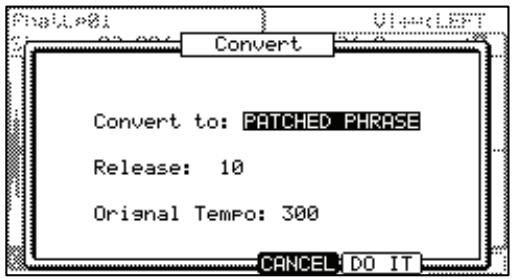
Note: The auto-calculated tempo is done with the original pitch (Tune), regardless of the TUNE setting. Depending upon the sample, the auto-calculated tempo may not work correctly.
The Patched Phrase sample is each region sample and the trigger timing of the sample together. If the original tempo setting is not correct, it may not work correctly.
- After adjusting each parameter, press [F5] (DO IT)
The MPC5000 will start processing the PACHED PHRASE, and then the 'TRIM' page with the new sample will be displayed.
The new name of the patched phrase sample will be the original sample with 'PP' added to the end.
For Example: Sample01 > Sample01PP.
You can assign the patched phrase sample to a pad in a program as well as an ordinary sample. The tempo of the patched phrase sample will change with the sequence tempo.
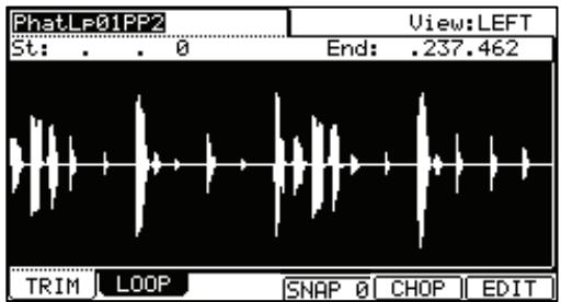
Note: You can not adjust the sample start/end point of a patched phrase in TRIM mode. The start/end points are still available for selecting regions to be edited.
Changing the Tune and Tempo of a Patched Phrase Sample
If you press the [WINDOW] button in the 'Sample' field of the TRIM page, the Sample window will be displayed. You can set the sample name, tune, and the original tempo of the patched phrase.
Sample name:
A new name can be entered here.
Tune:
This sets the pitch of the patched phrase.
Original tempo:
This sets the tempo of the patched phrase. The Original tempo setting is important for playing the patched phrase correctly. If the patched phrase sample cannot be played with the correct tempo, adjust the Original tempo.
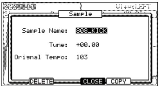
Pressing [F4] (CLOSE) will go back to the TRIM page.
Pressing [F2] (DELETE) will remove the selected file from memory.
Editing Regions
By using the Edit function in the CHOP SHOP Page, you can divide one region into two regions or combine continuous regions into one region. You can also extract the selected region as another sample.
- In the CHOP SHOP Page, press the [F6] (EDIT) button.
The Region Edit window will be displayed.
- In the 'Edit' field, select the type you wish to edit.
EXTRACT
Extracts the selected region as another sample.
- In the 'Edit' field, select EXTRACT.
Region:
You select the number of the region you wish to extract.
New sample:
Sets the new name for the new sample here.
- Press the [F5] (DO IT) button.
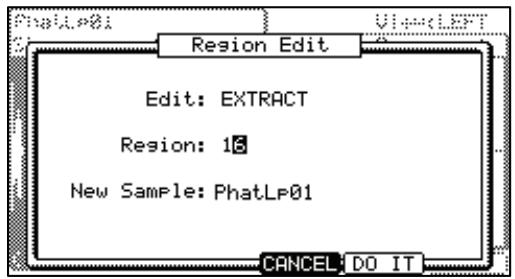
The MPC5000 will start the extract process. Pressing [F4] (Cancel) will cancel the extract and the display go back to the CHOP SHOP Page.
DIVIDE REGION
Divides the selected region into two regions.
- In the 'Edit' field, select DIVIDE REGION.
Region:
Selects the number of the region to divide.
- Press [F5] (DO IT).
The MPC5000 will start dividing the region into two regions. Pressing [F4] (Cancel) will cancel the process and the display will go back to the CHOP SHOP Page.
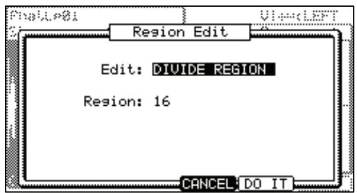
Combine Region
Combines an adjacent range of regions to one region.
- In the 'Edit' field, select COMBINE REGION.
Region
Selects the number of regions to combine.
For example, if you set this 1-5, the regions from 1 to 5 will be combined.
- Press the [F5] (DO IT) button.
The MPC5000 will start combining the regions. Pressing [F4] (Cancel) will cancel the process and the display will go back to the CHOP SHOP Page.
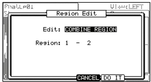
RESTORE
This converts the selected Patched Phrase to an ordinary sample.
Tempo
This sets the tempo of the sample.
[F4] (CANCEL)
Cancels the Extract process.
- Press the [F5] (DO IT) button.
The MPC5000 will begin processing the Restore, and then the display will go back to the TRIM page.
![AKAI MPC5000 - [F4] (CANCEL) - 1](/content/2025/01/152537/images/3477df93bc30091d8ebaf5b4be38c935bd31c4c55f2f7a526b01b22afcd56de2.jpg)
Setting the loop
The loop feature plays the sample repeatedly. With the loop feature, you can play the sample from the loop point to the end point repeatedly. To activate the loop feature, turn on the 'loop' field, which is located in the upper right corner of the LOOP page. When the loop feature is on, the MPC5000 first plays the part from the start point set in the TRIM page to the end point, and then plays the part from the loop point set in the LOOP page to the end point repeatedly.
Note: If you set the pad to ONE SHOT in the PROGRAM mode, the MPC5000 will play the sample assigned to that pad like when the loop is off, even when the loop feature is on. When you use the loop feature, set the pad's play mode to NOTE ON. For more information, see the 'Note On vs. One Shot' section on page 106.
Adjusting the loop point
- In TRIM mode, press the [F2] (LOOP) button.
The LOOP page will be displayed.
- Select the 'Sample' field and select a sample you wish to edit.
The 'Sample' field is located in the upper left corner of the screen, which displays the sample name. It displays the waveform of the selected sample.
- Select the 'Lp' (loop)' field and adjust the loop point.
You can change the loop point by turning the [DATA] wheel.
If you press the left/right cursor key while holding the [SHIFT] button, you can select the digit with the [DATA] wheel.
You can also enter the value directly using the Numeric keys.
- Hit the pad to check the loop point.
When you hit the pad, the MPC5000 plays the sample. The playback method varies depending on the pad.
[PAD 13] (PLAY LOOP)
The MPC5000 will play the sample from the loop point to the end point repeatedly.
[PAD 14] (PLAY TO)
The MPC5000 will play the part before the loop point.
[PAD 15] (PLAY FROM)
The MPC5000 will play the sample from the loop point.
[PAD 16] (PLAY ALL)
The MPC5000 will play the whole sample.
[PAD 1] to [PAD 12]
The MPC5000 will first play from the start point to the end point, and then play from the loop point to the end point repeatedly.
Adjusting the end point
- Select the 'End' field and adjust the end point.
Note: The end point of the loop is the same with the end point of the sample, which is set in the TRIM page.
If you change the end point in the LOOP page, the end point in the TRIM page will be changed as well.
Zooming In/Out of the Waveform
With the Loop Fine window, you can zoom into a part of the waveform and edit the part in details. Press the [WINDOW] button in the LOOP page, when the cursor is either in the 'Lp' (loop) or 'End' field, and the Loop Fine window will be displayed.
The waveform of the end point is displayed in the left of the waveform display, and the waveform of the loop point in the right, so you can adjust the loop and end points while checking the relationship of the waveform. If you press the [F2] (ZOOM-) button the waveform will be zoomed out, if you press the [F3] (ZOOM+) button, it will be zoomed in.
LINEAR and LOGARITHMIC Displays
The vertical axis indicates the waveform's level. Normally, the waveform display is set to LINEAR, which displays the sample level as it is. However, some parts (fade out part etc...) may not be displayed as the waveform if the level is too low. In this case, you can switch to the LOG (logarithmic) display by pressing the [F5] (LOG) button and you can see the parts whose level is low. When you switch to the LOG mode, the display in the [F5] button will change to LINEAR. To switch back to the LINEAR mode, press the [F5] button again.
Linking the Loop Point to the Start Point
When you loop the whole sample (ex: loop the phrase sample to the rhythm), it is better to set the start and loop point to the same value so that you can change both points at the same time.
- In the LOOP page, select the '(start/loop link)' field.
- Turn the [DATA] wheel and set the field to (locked by the key).
Loop point is set to the value of the start point. If you change the loop point later, the start point will be changed as well and vice versa.
If you reset the 'start/loop link' field, you can set the start point and loop point separately.
Auto Phrase Loop
You can make a loop automatically match the tempo of the phrase sample.
- In TRIM mode, press the [F2] (LOOP) button.
The LOOP page will be displayed. - In the 'Lp' field, set the loop start point of the phrase sample.
- Press the [F5] (AUTO L) button.
The Auto Phrase Loop window will be displayed. In the Tempo' field, the tempo of the phrase sample is displayed with calculated by the MPC5000. Set the tempo if you know it.
In 'Beat' field, set the number of beat you wish to loop. For example, if you want to loop 1 bar of 4/4 , set to 4.
Note: You cannot set the beat number longer than the length of the sample.
[F4] (Cancel):
You can cancel the Auto Phrase Loop by pressing this button.
- Press the [F5] (DO IT) button.
The MPC5000 will start the Auto Phrase Loop.
Note: Depending upon the sample, such as a single snare hit, the tempo may not be calculated correctly.
Chapter 13: Sample and Synth Programs
In this section, you will learn how to edit a program. This is done in the PROGRAM mode, which can be accessed by pressing the [MODE] button and then the [PAD 6] (PROGRAM).
Sample Programs
Creating a Sample Program
To create a new sample program, proceed as follows.
Note: the MPC5000 comes from the factory with preset sounds loaded on the internal ROM. These programs are set to load automatically when the MPC5000 is turned on. You can set the MPC5000 to start without loading it's internal ROM by turning off Autoload. For more information, see the 'Autoload' on page 160.
- Press [MODE] and [PAD 6] (PROGRAM).
This will enter PROGRAM mode.
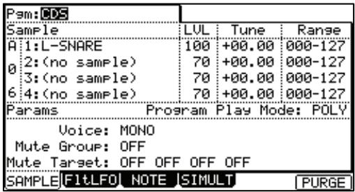
- Select the 'Pgm' field and press [WINDOW].
The Program window will be displayed.
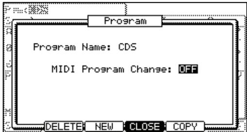
- Press the [F3] (NEW) button.
The New Program window will be displayed.
- In the 'New name' field, turn the [DATA] wheel.
The name window will be displayed. Set the name for the new program and press the [F5] (ENTER) button. For more information about setting the name, see the 'Setting Names' section on page 18.
- In the 'Type' field, select Sample
This is a program that will contain samples. For more information on Synth programs see the section entitled 'Synth Programs' on page 115.
- Press [F5] (DO IT).
The new program will be created. The new program is 'empty', which means it does not have any samples assigned. To play the program, you need to assign samples to the pads in the Sample page of PROGRAM mode.
■Assigning Samples to Pads
A Sample Program consists of Samples, assigned to individual pads. In this section, you will learn how to assign samples to a Sample Program's pads and how to control how the samples are played.
- Press the [MODE] button and then the [PAD 6] (PROGRAM).
When you press the [MODE] button, its LED will blink. When you press the [PAD 6] with the [MODE] button's LED blinking, you will enter PROGRAM mode. Pressing the [F1] (SAMPLE) button displays the SAMPLE page. The 'Pgm' field in the upper left corner displays the name of the currently selected program. You can change the selected program in the 'Pgm' field.
- Hit the pad you wish to assign a sample to.
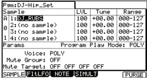
The pad number will be displayed in the left. The pad number will change according to the pad you hit.
- Select the first sample field, labeled as '1' and select the sample to assign to the pad.
In the example shown, the sample DJ_RUBS is displayed in the first sample field.
You can select any sample currently stored in the MPC5000's RAM by turning the [DATA] wheel. You can assign samples by selecting '2' through '4' fields. If you assign samples to '2' through '4' fields, you can play several samples at once.
For more information on loading and saving samples, see "Saving a Sample" on page 150.
Note On vs. One Shot
When you play a sample by hitting the pad, the sample will be played to the end. This is useful when you want to play short drum sounds. However, when you play a long sample such as a phrase sample, it is better to set the MPC5000 to play the sample only while you hold the pad. In this section, you will learn how to play the sample only as long as the pad is pressed.
- In the Sample page of PROGRAM mode, hit the pad you wish to change.
The pad number display in the left of the screen will change according to the pad that you hit.
- Select the '1' field, and press the [WINDOW] button.
The PLAY MODE window will be displayed.
- In the '1' field select one of the following:
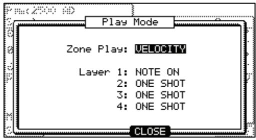
ONE SHOT
The MPC5000 plays the sample until the end regardless of how long you hold the pad.
NOTE ON
The MPC5000 plays the sample only while you hold the pad.
- Select fields '2' - '4' to adjust each sample assigned to the pad individually.
Note: When you loop the sample, set the play mode to NOTE ON. When you select ONE SHOT, a sample will NOT loop, even when the sample's loop is set to ON.
Volume and Tuning For a Sample
You can set volume and tuning for samples that are assigned to a pad.
- In the Sample page of PROGRAM mode, hit the pad you wish to edit.
The pad number display in the left of the screen will change according to the pad you hit.
-
Select the 'Lvl' field.
-
Adjust the volume to the desired level.
You can audition the level changes by hitting the pad as you set the level.
- Select the 'Tune' field.
The 'Tune' field has two fields divided by a decimal point.
The 2 digits on the left set tuning by semitones.
The 2 digits on the right change the tuning by cents (100 cents = 1 semitone).
- Set the tune to the desired pitch offset.
You can audition the tune changes by hitting the pad as you adjust the pitch.
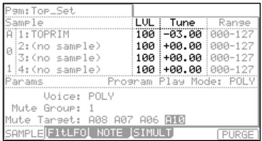
Velocity
You can control the sample volume by velocity (how hard you hit the pad). With this feature, you can play the pads like real drums; when you hit the pad strongly, the sound will be loud and vice versa.
- In the Sample page of PROGRAM mode, hit the pad you wish to edit.
The pad number display in the left of the screen will change according to the pad you hit.
-
Select the 'Lvl' field.
-
Press the [WINDOW] button.
The Amp Envelope window will be displayed.
- Select the 'V>Level' field.
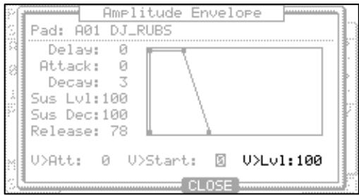
- Adjust the field to the desired value while checking the level by hitting the desired pad.
If you set this field to 0, the sample will be played back at the maximum level regardless of the amount of pressure. The larger you set the value, the bigger the difference of the level will be. - Press [F4] (CLOSE) to return to the Sample page.
You can set more detailed settings for sample volume by using the other parameters in the Amp Envelope window. For more information about setting them, see the section entitled 'Amplitude Envelope' on page 109.
Velocity / Cycle / Random Sample Switching (Zone Play)
Samples assigned to the pads can be switched to play in three different ways, depending on your desired play mode.
Velocity Sample Switching
When you assign more than one sample to a pad, you can switch between samples by how hard you hit the pad.
- In the Sample page of PROGRAM mode, select the desired pad by hitting it.
- Assign the samples to the '1' field and the '2' field.
- Press [WINDOW].
This will open the PLAY MODE Window.
- In the 'Zone Play' field, select VELOCITY.
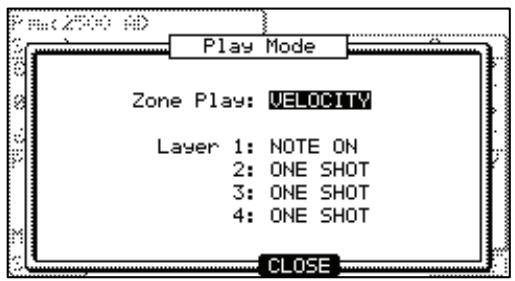
Note: VECOCITY is the default setting for pads.
- Press [F4] (CLOSE) to exit the 'PLAY MODE' window.
- Select the 'Range' field in the same row with the '1' field, and set the velocity range to trigger the sample assigned to the field.
The 'Range' field has two fields to set the upper and the lower limits. You can set the lower limit in the left field and the upper limit in the right field. Here, set the upper limit (the right field) to 63.
- Select the 'Range' field in the same row with the '2' field, and set the velocity range to trigger the sample assigned to the field.
In this example, set the lower limit (the left field) to 64. - Check the result by hitting the pad.
If you hit the pad hard, the MPC5000 will play the sample assigned to the 2^ field. If you hit the pad softly, the MPC5000 will play the sample assigned to the 1^ field.
Tip: How hard a pad is hit is measured in 128 steps (0 to 127). The maximum level is 127. This is the same as MIDI velocity, which indicates the pressure used to play the keyboard.
Tip: You can also use the Q-LINK slider to switch layers. For more information, see 'Q-LINK Controllers' on page 163.
Cycle Switching
Cycle Switching will play a new sample zone each time the pad is played in numerical order. In other words, the samples will cycle through as follows: 1, 2, 3, 4, 1, 2, 3, 4... etc.
To enable Cycle Switching, do the following:
- From PROGRAM Mode, select any sample on the pad you wish to assign Cycle Switching.
- Press [WINDOW]
- Set the 'Zone Play' field to CYCLE.
Random Sample Switching
Random sample switching will allow all the samples assigned to the pads to be selected randomly. This way, every time you hit a pad, one of the four assigned samples will be randomly chosen to play.
To enable Random Zone Play, do the following:
- From PROGRAM Mode, select any sample on the pad you wish to assign Random Sample Switching.
- Press [WINDOW]
- Set the 'Zone Play' field to RANDOM.
Tip: Try assigning four samples to a pad, turn on Random Zone Play, and play the pad using Note Repeat. Also, try assigning different sections of a chopped loop to a Random Zone Pad.
Changing Pitch with Velocity
You can control the sample pitch by velocity (how hard you hit the pad).
- In the Sample page of PROGRAM mode, hit the pad you wish to edit.
The pad number display in the left of screen will change according to the pad you hit.
-
Select the 'Tune' field.
-
Press the [WINDOW] button.
The PITCH FUNCTION window will be displayed.
-
Select the 'V>Pitch' field.
-
Adjust the field to the desired value while checking the level by hitting the desired pad.
If you set this field to 0, the sample pitch will not change with velocity. The larger you set the value, the higher the pitch will be.
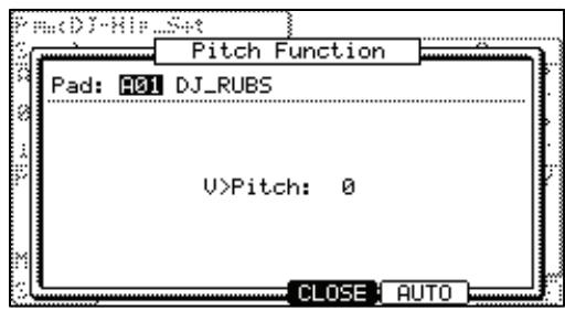
Playing several samples with one pad
You can assign up to 4 samples to one pad. When you assign more than one sample to a pad, you can play several samples by hitting one pad.
- In the Sample page of PROGRAM mode, select the desired pad.
The pad number display in the left of the screen will change according to the pad you hit.
The 'Pgm' field in the upper left corner displays the name of the currently selected program. You can change the currently selected program in the 'Pgm' field.
- Select the '1' field and select the sample to assign to the pad.
You can select the samples currently saved in the MPC5000's memory by turning the [DATA] wheel.
- Select the '2' field and select the sample to assign it to the pad.
When you hit the pad, all the samples assigned to the selected pad will play simultaneously.
- Repeat step 03 for fields '3' and '4'.
Up to four samples can be played per pad.
■Assigning One Sample across All Pads (Auto-Chromatic)
Samples can be automatically assigned chromatically to the drum pads. The 64 drum pads, (PAD A01 - D16) will correspond to a note range of 35 - 98 on a MIDI keyboard. This allows you to easily play a melody with a single sample.
To assign a sample chromatically, do the following.
-
Press [MODE] + [PAD6] (program).
-
Press a pad.
-
Assign the sample you wish to chromatically assign to the selected pad.
-
Select the 'Tune' column and press the [WINDOW] button.
The 'Pitch Function' window will be displayed.
- Press [F5] (AUTO) to open the Auto Chromatic Assign window.
In the Source and Original key fields, the display characters show the MIDI note number and drum pad number: 36/A01 is MIDI note 36/pad bank A, drum pad number 1.
- Select the sound and MIDI note number to be assigned in the Source field.
You can select the sound with the drum pads or the DATA wheel (the name of the sound also appears).
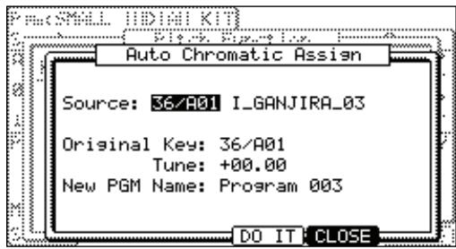
Note: The parameters of the sound selected here will be copied to each note.
- In the 'Original key' field, select the note on the MIDI keyboard/drum pad which will play the original pitch of the sound.
You can also use the 'Tune' setting to apply an offset to the original pitch. This setting will affect each note.
- In the 'New PGM name' field, you can enter a new name for the Chromatic program to be created.
- Press [DO IT] to create a new auto chromatically assigned program.
Simultaneous Playing of Multiple Pads
Simultaneous play will allow the triggering of up to four other pads by hitting just one pad. To turn on simultaneous play, do the following:
- Press [MODE] + [PAD 6] to enter PROGRAM Mode.
- Press [F4] (SIMULT).
This will open the 'Simultaneous Play' tab.
- In the Pad field, select the pad you wish to use to trigger other pads.
You can select different pads by selecting the pad with the [DATA] wheel, or you can select a pad by hitting it while the cursor is in this field.
- Select the field 'Simult1'
Select the first pad you would like to be triggered simultaneously with the pad selected in step 03.
- You can select the pad to be played by turning the [DATA] wheel, or by hitting a pad while the cursor is in this field.
Repeat the process for 'Simult:' numbers two through four.
Now, hitting the pad selected in step 3 will play the pads listed in 'Simult' 1-4 as well as its own sound. Note that if one of the other pads are struck, the other pads do not play. Only the pad selected in step 3 will trigger the other pads. This can be used to play extremely difficult percussive parts with ease.
Setting Envelopes
You can set the envelope for the samples assigned to the pads. The MPC5000 has two envelopes per pad for sample programs, one is the Amplitude Envelope, which controls volume and the other is the Filter envelope for controlling sound character.
Amplitude Envelope
- In the Sample page of PROGRAM mode, select the pad you wish to make a setting by hitting it.
- In the 'Lvl' field, press the [WINDOW] button.
The Amp Envelope window will be displayed
'Pad' field:
The selected pad will be displayed.
'Delay' field:
This field sets the amount of silence that will be played before triggering a sample; the larger the value, the longer the delay.
Attack field:
You can set the sample's attack time in this field. The larger the value, the longer it will take for the sound to start. (Fade in)
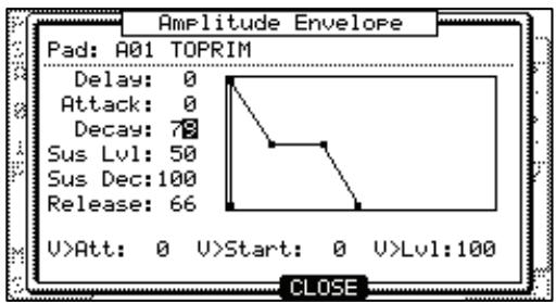
'Decay' field:
This field sets how long a sound will fade out before the sound enters the Sustain part of the envelope.
'Sus Lvl' (Sustain Level) field
This parameter is the level that the sample reaches when the decay portion is finished. This parameter has no effect on samples set to ONE SHOT.
'Sus Dec' (Sustain Decay) field
This parameter determines the time it takes for the 'Sustain Decay' stage to drop to zero. If this parameter is set to 100, the envelope will sustain for as long as the key is held down. This parameter has no effect on samples set to ONE SHOT.
'Release' field
This sets the amount of time the envelope will take to get from its current level to zero after the note has been released. The higher the number, the longer it will take to fade out.
'V > Attack' field:
You can control the sample's attack time by velocity. The larger you set the value, the slower the sound will start by velocity. If you set this field to 0, the attack time is constant, regardless of the velocity.
V > Start' field:
You can control the sample's start point by velocity. The larger you set the value, the bigger delay the sample start point will be by velocity. If you set this field to 0, the sample start point is constant, regardless of the velocity.
'V > Level' field:
You can control the sample's volume by velocity. The larger you set the value, the bigger the difference of the level will be. If you set this field to 0, the sample will be played back at the maximum level regardless of the velocity.
Filter Envelope
- In the FILTER page of PROGRAM mode, select the pad you wish to filter by hitting it.
- In the 'Type' field, press the [WINDOW] button.
The Filter Envelope window will be displayed.
'Pad' field:
The selected pad will be displayed.
'Amount' field:
You can set the depth of the filter envelope. If you set this field to a + + value, the cut off frequency will start higher than the original cut off frequency and will follow the envelope level. If you set this field to a - value, the cut off frequency will start lower than the original cut off frequency and go back to the original frequency within the time set in the 'Time' field.
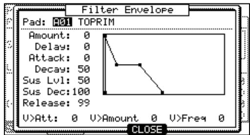
'Delay' field:
This field sets the amount of time that will elapse before the envelope will affect the filter; the larger the value, the longer the delay.
Attack' field:
You can set the filter's attack time in this field. The larger the value, the longer it will take for the filter to change. (Fade in)
'Decay' field:
This field sets how long a filter will fade out before the filter enters the Sustain part of the envelope.
'Sus Lvl' (Sustain Level) field
This parameter is the level that the sample reaches when the decay portion is finished. This parameter has no effect on samples set to ONE SHOT.
'Sus Dec' (Sustain Decay) field
This parameter determines the time it takes for the 'Sustain Decay' stage to drop to zero. If this parameter is set to 100, the envelope will sustain for as long as the key is held down. This parameter has no effect on samples set to ONE SHOT.
'Release' field
This sets the amount of time the envelope will take to get from its current level to zero after the note has been released. The higher the number, the longer it will take to fade out.
'V>Time' field:
You can control the filter envelope time by velocity. If you set this field to a + value, the time will be closer to the time set in the 'Time' field with higher velocity. If you set this field to a - value, it works exactly opposite. If you set this field to 0, the time is constant by velocity.
'V>Amount' field:
You can control the depth by velocity. If you set this field to a + value, the beginning cut off frequency will start closer to the frequency set in the 'Amount' field with higher velocity. If you set this field to a - value, it works exactly opposite. If you set this field to 0, the depth is constant by velocity.
'V>Freq' field:
You can control the cut-off frequency with velocity. The higher the velocity, the higher the cut-off frequency. If you set this field to 0, the cut-off frequency is constant by velocity.
Using Filters with Sample Programs
Each pad of a sample program has a 'Filter'. You can edit the sound of the sample by editing this parameter. This is done in the FltLFO page of PROGRAM mode.
Setting the Filter
- In PROGRAM mode, press the [F2] (FltLFO) button.
The 'FltLFO' page will be displayed. You can select the program to edit in the 'Pgm' field.
- Select the pad you wish to edit for the sound by hitting it.
The 'Pad' field displays the pad number of the selected pad. To the right of the pad number, the name of the sample assigned to the pad is displayed.
- Select the 'Type' field, and select which filter type to use.
The MPC5000 has several types of filters to modify the sound. With these filters, you can cut or boost the specific frequency of the sound. The following types are
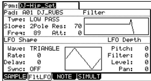
available:
LoPass
This filter cuts out the high frequencies and passes the low frequencies.
HiPass
This filter cuts out the low frequencies and passes the high frequencies.
BPass
Band Pass Filter. This filter passes the selected frequencies and cuts out the other frequencies.
BStop
Band Stop Filter. This filter cuts the selected frequencies and passes all other frequencies.
BBoost
Band Boost Filter This filter boosts the selected frequencies and passes all other frequencies.
Model1
This is an analog style 4-pole filter, modeled after a famous vintage semi-modular synthesizer. This filter will clip (distort) when fed a loud input level.
Model2
This is another analog style filter with a mellow resonance, and slight fattening distortion in the lower frequencies.
Model3
This filter is a crazy analog modeling filter capable of howling, piercing resonance and jaw-rattling sub frequencies. Watch your speakers!
Vocal1
This filter is a formant filter modeled on the human voice which emulates the "ah" and "oo" vowel sounds.
Vocal2
A 3-band formant filter which emulates the "oh" and "ee" vowel sounds.
Vocal3
A 5-band formant filter based on an idealized model of the vocal tract.
OFF
No filter is used.
- Select the 'Slope' field and adjust the Slope.
The Slope controls how extreme the effect of the filter will be. A one or two pole slope will yield a subtle effect, where an eight pole slope will be much more pronounced.
- Select the 'Freq' field and set the cutoff frequency.
The cut off frequency is the frequency that triggers the filter. When you select the LOW PASS filter, if you set the cutoff frequency too low, the sound will seem dull. This is because most of the higher frequencies of sound are attenuated by the filter. When you select the HIGH PASS filter, if you set the cutoff frequency too high, most of the lower frequencies are attenuated, which results in a more hollow sound.
- Set the 'Res' field to adjust the resonance of the filter.
If you set the resonance value at a larger value, the frequencies set in the 'Freq' field will be boosted more. It is hard to describe the effect of the resonance, because it differs depending on the cut off frequency and filter type. Experiment with several settings in the 'Type' field, 'Freq' field, and 'Res' field.
Note: If you notice distortion while using the FILTER, you can use the 'Att' parameter to adjust the level of the signal sent to the filter, and remove the unwanted distortion.
Controlling the Filter with Velocity
You can control the cutoff frequency of the filter by velocity. With this feature, you can control the sound by changing the velocity used to hit the pad.
- In the PROGRAM mode, press the [F2] (FILTER) button.
The FILTER page will be displayed.
- Select the desired pad by hitting it.
The 'Pad' field displays the pad number of the selected pad.
- Select any of the 'Type', 'Freq', or 'Res' fields and press the [WINDOW] button.
The Filter Envelope window will be displayed.
- Select the 'V> Freq' field.
The larger the value you set, the more drastic a change you can make to a sample by how hard you hit the pad.
Refer to 'Filter Envelope' on page 110 about the other parameters in the Filter Envelope window.
Mute groups
Normally, when you hit a pad when another pad is played back, the samples of these two pads will be played back overlapped. With the mute group function, you can stop the playback of the sample of a pad when you hit another pad. Using this function, you can simulate the open/close hi-hat. You can use this function by setting two pads to the same mute group. The pads set to the same mute group will not be played at the same time.
- In PROGRAM mode, press the [F1] (SAMPLE) button to select the Sample page.
- Select one of the pads to set the mute group, by hitting the pad.
- In the 'Mute Group' field, select a number.
You can set any number except OFF.
- Select the other pad to set the mute group, by hitting the pad.
- In the 'Mute Group' field, set the same number you set for the first pad in the step 3.
You must set the same number to activate the mute group.
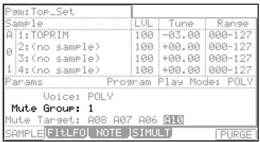
Hit one pad while playing back another. The first sample will be stopped and only the sample of the pad you hit will by played.
Tip: You can set the mute group to more than two pads. Up to 32 different mute groups can be assigned.
Note: If you set the 'Play' field to MONO, each pad sample cannot be played with Polyphony, regardless of which mute group you assign it to. When you use mute groups, set the 'Play' field to POLY.
Limiting the Number of Voices in a Program
Normally, the pad sounds in the program are played polyphonically - when you hit the pad several times, you hear a new instance of the sound every time. But you may wish to play the sound monophonically - meaning that each new pad strike will silence the previous strike. This is useful in programs such as programs being made by the SLICED SAMPLE function. In this case, you can set the limit of voice number on the pad in the program.
- In the PROGRAM mode, press the [F1] (SAMPLE) button
- In the 'Program Play' field, select either POLY or MONO.
POLY
The MPC5000 overlaps the sound in the program. (Polyphony)
MONO
The MPC5000 does not overlap the sound in the program. (Monophony)
Note: This is the setting for the whole Program, but you can set each pad in a program to individually play in MONO. Refer to 'Setting Voice Overlap' on page 112.
Setting Voice Overlap
Normally, when you hit the same pad several times, the same sound will be overlapped. When you use the MPC5000 as a drum machine, you can make the performance sound natural with this feature. However, when you are using a phrase sample, it may be better not to overlap the same sound. With the voice overlap function, you can set the MPC5000 not to overlap the same pad sound.
- In the PROGRAM mode, press the [F1] (SAMPLE) button.
The Sample page will be displayed.
- Select the desired pad by hitting it.
- In the 'Voice Overlap' field, select MONO.
POLY
The MPC5000 overlaps the sound.
MONO
The MPC5000 does not overlap the sound. If you select MONO, when you hit the pad several times, only the last pad that was hit will be played.
Note: If you set the 'Play' field to MONO, each pad sample cannot be played with Polyphony, regardless of the Voice overlap setting. When you use the voice overlap function, set the 'Play' field to POLY.
Mute Target feature
Mute Target works similarly to Mute Group. The main difference is that Mute Target can be set to work in only one direction.
For example, you can use Mute Target to have Pad A01 Mute Pad A02. The advantage of this is that when Pad A02 is played, Pad A01 will not be muted.
You can set a maximum of four mute targets per pad.

Low Frequency Oscillators (LFO)
You can set the LFO on the pad sample in the Program. By using the LFO, you can get a more powerful sound. For example, if you set the Pitch in the LFO page, the pad sound can have the vibrato effect, and if you set the Level in the LFO, the pad sound can have the tremolo effect. The MPC5000 can set the Filter or Pan in the LFO page as well as the Pitch or Level.
- In the PROGRAM mode, press the [F2] (FltLFO) button.
The FltLFO page will be displayed. In the 'Pgm' field, you can select the Program you wish to edit.
- Select the desired pad by hitting it.
In the 'Pad' field, the selected pad will be displayed.
'Wave' field:
This field sets the wave for the LFO from TRANGLE, SINE, SQUARE, SAW, SAW DOWN, or RANDOM.
'Rate' field
This field sets the cycle (speed) of the LFO.
When the 'Sync' field is set to ON, this setting value is based on the Beat and Tick. For example, if you wish to set the cycle of the LFO to one beat of the sequence, you would set this value to '01.00', if you want to set the cycle to an 1/8 note, set it to '00.48' and so on. The cycle (speed) will be changed with the tempo of the sequence.
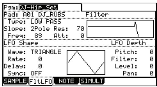
When the 'SYNC' field is set to OFF, the LFO will free run, without syncing to the sequencer.
'Delay' field
You can set the delay time (the time before starting the LFO). When 'Sync' is set to ON, this will be displayed in Beat and Tick. For example, if you wish to start the LFO after one beat from starting from the point of triggering a sample, set it to '01.00'.
When the 'SYNC' field is set to OFF, the 'Delay' field will not sync to the sequencer.
'Sync' field
This field sets whether the LFO will sync to the sequencer.
'Pitch' field (0-100)
This field sets the amount the LFO will be sent to the pitch of the selected pad, yielding a vibrato-type effect. The lower the value, the less pitch variation you will get, and vice versa the higher this value, the more pitch variation.
'Filter' field (0 - 100)
This field sets the amount the LFO will be sent to the filter cutoff of the selected pad. This will add a sweeping wow sort of effect. The lower this value, the less the wow becomes, and vice versa.
'Level' field (0 - 100)
This field sets the amount the LFO will be sent to the level of the selected pad, yielding a tremolo sounding effect. The lower this value, the less tremolo effect and the larger the value, the more tremolo effect.
'Pan' field (0 - 100)
This field sets the amount the LFO will be sent to the pan parameter of the selected pad.
The lower this value, the narrower the panning effect, the larger this value, the wider the panning effect will be.
Purge Unused Samples
When you use the MPC5000 to record or load several samples, you may have unused samples (samples not assigned to any pads in the program) in the MPC5000's memory. In this case, it is time consuming to browse the contents of the program for unused samples and delete them one by one. With the PURGE function, you can delete all the unused samples at the same time.
- In PROGRAM mode, press [F1] (SAMPLE).
The SAMPLE page will be displayed.
- Press [F6] (PURGE).
The Purge Samples window will be displayed.
- Press [F5] (DO IT).
All the samples which are not assigned to any program will be deleted at the same time.
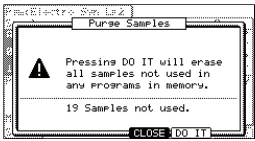
Synth Programs
New to the MPC5000 are virtual analog, or 'Synth' programs. These differ from sample programs in that rather than using pre recorded sounds, the sound is created by a method called 'subtractive synthesis'. From smooth, whistling leads, to huge, booming basses, to lush, spacious pads, this method of creating sound can be used to create a vast array of sounds.
About Subtractive Synthesis
The concept of a synthesizer is an instrument that is capable of producing a very wide range of sounds electronically. The huge popularity and continued development of synths since the late 60s is due, in great part, to this ability to offer so many different types of sound textures in one box.
A synthesizer's ability to produce such an incredible variety of sound comes from its basic design: it electronically simulates the fundamental components of sound and gives you control over each part. The term synthesizer means to "combine parts into a whole". And that's exactly what a synthesizer does: the essential ingredients of sound are presented as separate parts which are then "re-assembled" as an audible sound.
The MPC5000's synth generates sound by emulating, or "modeling," the behavior of an analog synthesizer. Oscillators generate the raw sounds. The oscillators are then fed into the filters, which in turn are fed into the amplifiers. As the signal moves through that basic path, you are able to adjust the mix of the signal at several points, apply various modulations and envelopes, and add effects. In this way, the MPC5000's synth can generate a virtually limitless variety of sounds.
Voltage Controlled Oscillators (VCO)
The oscillators are where sound is born. You may have heard that what you perceive as "sound" is simply vibrating air molecules hitting your eardrums. That vibration has to start somewhere, and in the MPC5000's synth section, it comes from the oscillators. By varying the frequency of the vibration, the oscillators can produce different pitches, which are heard as musical notes. By adjusting the waveform type and shape, the oscillators can produce various harmonics, which are heard as different timbres. Each of the MPC5000's synth voices contains three oscillators.
Voltage Controlled Filters (VCF)
The sound produced by the oscillators is very raw, and usually not suitable to be used directly in an instrument. In order to bring out the sonic textures you have in mind, you will typically want to dampen certain harmonics and boost others. This is where the filter comes in. The filter alters the frequency content of the signal, and can have a drastic effect on the sound. A filter typically allows you to adjust its Cutoff Frequency, which represents the range of harmonics that the filter operates on, as well as its Resonance, which determines how much boost is given to harmonics around the cutoff frequency. The MPC5000 has eleven different filter types, each with its own character and sonic flavor.
LFO
LFO stands for "low frequency oscillator". Unlike the normal oscillators, however, the LFOs are not designed for producing sound. Instead, their purpose is to tweak a program parameter according to a looping pattern. For example, if you are looking to add some vibrato to your instrument, you'll need the pitch to continuously waver up and down. An LFO is perfect for this application. Simply hooking up an LFO to the oscillator pitch parameter will get you the effect you need. Each of the MPC5000's voices contains two LFOs.
Envelopes (ENV)
If you hit a note on a piano, you'll hear a burst of sound energy as the hammer strikes the string, followed by lower level of loudness as you hold down the note and let the string ring out, which fades quickly as soon as you release the note and the damper is applied. Synthesizer designers model this behavior using ADSR envelopes. ADSR stands for "attack, decay, sustain, release", and represents the different stages that the sound goes through over the life of the note. Since the most important application of the envelope is to control the loudness of the sound, the MPC5000 provides one envelope that is specifically designed for this purpose. This is the amp envelope. The MPC5000 also has an additional envelope to control the filter. This allows the Cutoff Frequency of the filter to be controlled independently of the sound's amplitude.
Playing an MPC5000's Synth Program.
Synth programs on the MPC5000 differ from Sample programs in that when you play a synth sound, a single sound is played chromatically across the pads. This allows you to create synth melodies and bass lines with ease.
The Synth Button
Pressing the [SYNTH] allows quick access to the synth program on the current track, automatically add the first loaded synth program to the current track, or if no synth program is loaded, create a new, generic synth program for you to work with. It's best to think of the [SYNTH] button as a quick-fix shortcut to quickly get into synth programming.
Creating a Synth Program
To create a new synth program, do the following:
Note: the MPC5000 is set to load the preset program automatically when turned on. You can set the MPC5000 to start without loading the preset program. For more information, see the 'Autoload' section on page 160.
- Press [MODE] and [PAD 6] (PROGRAM). This will enter PROGRAM mode.
- Select the 'Pgm' field and press [WINDOW]. The Program window will be displayed as shown.
- Press the [F3] (NEW) button. The New Program window will be displayed as shown.
- In the 'New name' field, turn the [DATA] wheel. The name window will be displayed. Set the name for the new program and press the [F5] (DO IT) button. For more information about setting the name, see the 'Setting Names' section on page 18.
- In the 'Type' field, select Synth
- Press [F5] (DO IT). The new program will be created, and the Basic screen will be displayed. The new program is a default template of a very basic synth sound. You can play this sound by hitting the pads.
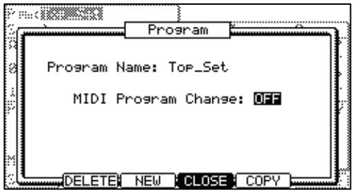
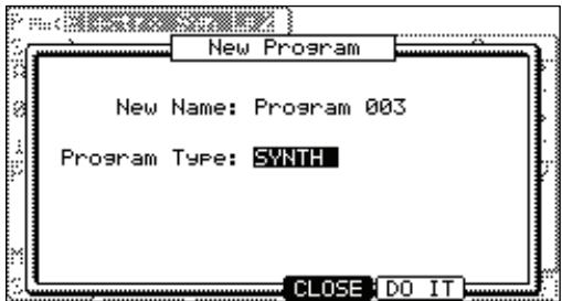
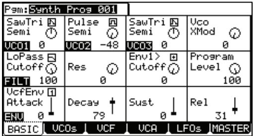
■ Editing with Q-LINK Controls
In addition to the [CURSOR] buttons and the [DATA] wheel, each parameter in SYNTH Mode is editable by moving its corresponding QLINK control, allowing for quick and intuitive editing of each parameter.
The image to the right displays a chart of which Q-Link control corresponds to which control on the screen. Every parameter in SYNTH mode is easily editable using Q-Links.
Basic Editing of a Synth Program
When a new program is created, the sound is very basic. To adjust the sound to your liking, do the following:
- From the MAIN screen, select a track that uses a synth program.
You can also create a new synth program as detailed in the previous section.
- Press [MODE] and [PAD 6] (PROGRAM)
This will bring you into PROGRAM mode where you can edit different parameters of your program.
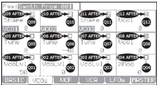
Note: you can also use the [SYNTH] button as a shortcut to jump to the last Synth program you edited.
- Press the [F1] (BASIC) button.
This will display the Basic page. Here, the most commonly used parameters for a synth program can be edited. Each parameter can be selected by using the [CURSOR] to select each field and turning the [DATA] wheel, or by using the Q-Links, as detailed in the section 'Editing with Q-LINK Controls' on page 117.
The label in the lower left corner indicates which component of the synth is to be edited.
VCO(1-3)
Different aspects of the Oscillators can be adjusted here.
'Wave' field
This selects the waveform for each of the three oscillators. The following shapes are available:
'Sine'
A very pure and simple tone with very little overtones; "mellow" sounding
'SawTri'
This waveform has a shape varying from a triangle wave to a saw wave, depending on the setting of the 'SHAPE' control, which is located on the VCO page. A Triangle wave has a fuller sound than a sine wave, but still has very little overtones. A Saw wave a harsh, aggressive sounding wave, with lots of overtones.
'Pulse'
Ranges from a square wave to varying degrees of pulse widths. Generally a more hollow sound, approaching nasalness as the wave gets thinner.
'WNoise', 'PNoise', 'RNoise'
Three different flavors of noise are available - White, Pink and Red. Each has its own sound, white being the most content rich and 'coldest' sounding, and red being most 'warm' sounding.
'PWM'
PWM stands for Pulse Width Modulation. This waveform is special, in that it is a Pulse wave whose shape is hard-wired to LFO 2. This gives this waveform a range of sounds from a classic warbling tone, to a buzzing, harsh sound, rich with overtones.
'SEMI'
Adjusts the tuning of each oscillator in semitones. Each OSC can be tuned +/- four octaves by semitones.
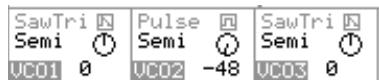
Vco XMod
This parameter controls the amount of oscillator cross modulation that is applied to VCO2 from VCO1. Cross modulation, also called FM synthesis, is when the output of VCO1 is used to modulate the frequency of VCO2. From vibrato-like pitch variations, to harsh clanging metallic noises, to bell type sounds, a broad range of sound is possible with cross modulation.
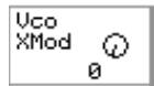
Filt
Various aspects of the filter are edited here.
'Filter Select' Field
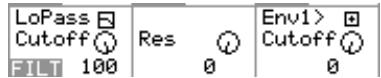
This field selects one of the various filter types. For information on which filter types are available, see page 120.
'Cutoff'
This represents the range of harmonics over which the filter operates.
'Res'
This field determines how much boost is given to harmonics around the cutoff frequency.
'Env1>Cutoff'
This determines how much of an effect envelope 1 will have on the filter. [Q-LINK AFTER 8] button toggles whether the effect of the envelope will be positive or negative.
'Program Level'
This parameter controls the overall volume of the program.
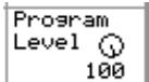
Env
Different aspects of the envelopes can be selected and changed here.
'VcfEnv' field.
Selects which envelope is being viewed. The parameters below will change to reflect the state of whichever envelope is chosen in this field.

'Attack'
This parameter determines how long an envelope will take to reach maximum level when a pad is struck. Sounds ranging from a slow swelling violin to drum-like attacks are possible by adjusting this parameter.
'Decay'
This parameter determines how long the sound will take to go from the attack phase to the sustain portion of the envelope.
'Sust'
For Envelope 2 (VcaEnv), 'Sust' determines how long a sound will sustain after the decay portion of the envelope finishes. For Envelope 1 (VcfEnv), 'Sust' sets the level at which the filter remains while the pad is being held after completion of decay phase.
'Rel'
Sets how long a sound will decay when the pad is released.
The Basic page is used to quickly edit the most commonly edited parameters in a Synth Program. More in depth editing will be detailed in the next sections.
VCOs
This page is where in-depth controls for the oscillators can be edited. To enter the VCO page, do the following:
- From the MAIN screen, select a track that uses a synth program. You can also create a new synth program as detailed in the previous section.
- Press [MODE] and [PAD 6] (PROGRAM)
This will bring you into PROGRAM mode where you can edit different parameters of your program.
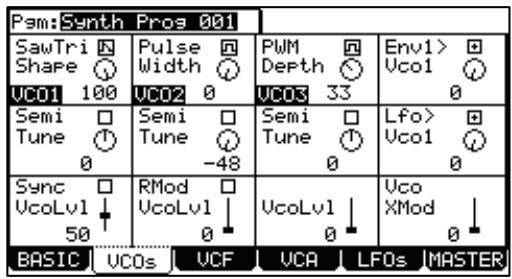
Note: You can also use the [SYNTH] button as a shortcut to jump to the last Synth program you edited.
- Press the [F2] (VCOs) button.
This will display the VCOs page. Here, the individual oscillators for a synth program can be edited. Each parameter can be selected by using the [CURSOR] to select each field and turning the [DATA] wheel.
- Edit the parameters of the VCOs page as desired.
The following parameters are available to be edited.
'Wave' field
This selects the waveform for each of the three oscillators. The following shapes are available:
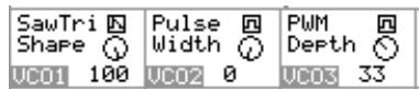
'Sine'
A very pure and simple tone with very little overtones. "Mellow" sounding
'SawTri'
This waveform has a shape varying from a triangle wave to a saw wave, depending on the setting of the 'SHAPE' control, which is located on the VCO page. A Triangle wave has a fuller sound than a sine wave, but still has very little overtones. A Saw wave a harsh, aggressive sounding wave, with lots of overtones.
When this wave is selected, an additional knob becomes available called 'SHAPE'. This knob controls the shape of the waveform. A setting of zero is a true triangle wave. Increasing this value changes the shape of this waveform, adding overtones, until it reached 100, which is a true saw wave.
'Pulse'
Ranges from a square wave to varying degrees of pulse widths. Generally a more hollow sound, approaching nasal a nasal-like quality as the wave gets thinner.
When this wave is selected, an additional knob becomes available called 'SHAPE'. This knob controls the shape of the waveform. A setting of zero is a very thin and nasal sounding wave, increasing this value changes the shape of this waveform, adding overtones, until it reached 50, which is a true square wave. Increasing this further decreases overtones, again yielding a very nasal sounding wave at 100.
'WNoise', 'PNoise', 'RNoise'
Three different flavors of noise are available - White, Pink and Red. Each has its own sound, white being the most content rich and 'coldest' sounding, and red being most 'warm' sounding.
PWM
PWM stands for Pulse Width Modulation. This waveform is special, in that it is a Pulse wave whose shape is hard-wired to LFO 2. This gives this waveform a range of sounds from a classic warbling tone, to a buzzing, harsh sound, rich with overtones.
When this wave is selected, an additional knob becomes available called 'DEPTH'. This knob controls amount of control LFO2 has over the width of the PWM oscillator.
'Env1> VCO1'
This knob sets how much effect envelope 1 will have on the pitch of VCO1. The corresponding Q-Link [AFTER] button toggles whether the effect of the envelope will be positive or negative.
This is most commonly used in conjunction with the 'Osc XMod' control.
'SEMI/FINE'
Selecting this control will toggle the 'TUNE' controls range.
When set to 'SEMI', the 'TUNE' control adjusts the tuning of each oscillator in semitones. Each VCO can be tuned +/- four octaves by semitones.
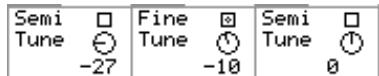
When set to 'FINE', the 'TUNE' control adjusts the tuning of each oscillator in +/- 100% of one semitone. This is useful for slightly detuning oscillators to fatten up the sound, or add a chorusing type effect.
'Lfo> VCO1'
This knob sets how much effect the LFO will have on the pitch of VCO1. This is useful for use in conjunction with the 'Osc XMod' control.
'SYNC'
Selecting this checkbox forces the frequency of VCO 1 to match the frequency of VCO 2 by locking their waves phase when the waves begin their rise and fall during their periodic cycles. When two sound waves have their phases synchronized, their cycles begin at exactly the same instant and stay locked throughout the cycle.
As the oscillators are tuned to wider intervals, a new set of harmonics are created resulting from two fundamental waves – with significantly different frequencies – being locked in phase: the waveforms start their cycles at the same time. This can result in harsh, distorted, waveforms perfect for aggressive dance-type synth leads, basses and effects.
'VcoLvl'
This field controls the volume of the selected oscillator in each column.
Tip: When VCO2's level is set to zero, the full amount of the oscillator is sent to VCO1, but the output is muted. This allows for the VCO2 to be silent, but still available for Sync and Ring Mod type sounds.
'RMod'
This check box turns on the Ring Mod. The Ring Mod is another classic analog tone modifier. It generates a series of sum-and-difference overtones from two input signals, in this case VCO1 in to VCO2, resulting often in a metallic, distorted character that is frequency dependent.
Vco XMod
This parameter controls the amount of oscillator cross modulation that is applied to VCO2 from VCO1. Cross modulation, also called FM synthesis, is when the output of VCO1 is used to modulate the frequency of VCO2. From vibrato-like pitch variations, to harsh clanging metallic noises, to bell type sounds, a broad range of sound is possible with cross modulation.
VCF
This page is where in-depth controls for the filter can be edited. To enter the VCF page, do the following:
- From the MAIN screen, select a track that uses a synth program. You can also create a new synth program as detailed in the previous section.
- Press [MODE] and [PAD 6] (PROGRAM) This will bring you into PROGRAM mode where you can edit different parameters of your program.
| Pam:Synth Pros 081 | |||
| Filter Cutoff 100 | Filter Res 0 | LoPass ☐ | Pole ☐ |
| Keyk > Cutoff 0 | Env1 > Cutoff 0 | LFO> Cutoff 0 | Uel> Cutoff 0 |
| Env1 Attack ↓ 0 | Env1 Decay ↑ 79 | Env1 Sust ↓ 0 | Env1 Rel ↓ 31 |
| BASIC VCOs UCF UCA LFOs MASTER | |||
Note: you can also use the [SYNTH] button as a shortcut to jump to the last Synth program you edited.
03. Press the [F3] (VCF) button.
This will display the VCF page. Here, the filter can be edited. Each parameter can be selected by using the [CURSOR] to select each field and turning the [DATA] wheel.
- Edit the parameters of the VCF page as desired.
The following parameters are available to be edited.
'Filter Cutoff'
Sets the frequency start point for the filter. This field also appears on the Basic page. See page 117 for more information.
'Filter Res'
Sets the amount of emphasis to be applied to the cutoff frequency of the filter. This field also appears on the Basic page. See page 117 for more information.
'Type'
Selects the type of filter to be used. This field also appears on the Basic page. See page 117 for more information.
The following types are available;
LoPass
This filter cuts out the high frequencies and passes the low frequencies.
HiPass
This filter cuts out the low frequencies and passes the high frequencies.
BPass
Band Pass Filter. This filter passes the selected frequencies and cuts out the other frequencies.
BStop
Band Stop Filter. This filter cuts the selected frequencies and passes all other frequencies.
BBoost
Band Boost Filter This filter boosts the selected frequencies and passes all other frequencies.
Model1
This is an analog style 4-pole filter, modeled after a famous vintage semi-modular synthesizer. This filter will clip (distort) when fed a loud input level.
Model2
This is another analog style filter with a mellow resonance, and slight fattening distortion in the lower frequencies.
Model3
This filter is a crazy analog modeling filter capable of howling, piercing resonance and jaw-rattling sub frequencies. Watch your speakers!
Vocal1
This filter is a formant filter modeled on the human voice. This 3-band (3 band pass filters) version emulates the "ah" and "oo" vowel sounds.
Vocal2
A 3-band formant filter which emulates the "oh" and "ee" vowel sounds.
Vocal3
A 5-band formant filter based on an idealized model of the vocal tract.
'Pole'
Selects how many poles the selected filter will be. A 2 pole filter will have a milder effect, where an 8 pole filter will have a more extreme effect. This field also appears on the Basic page. See page 117 for more information.
Note: Some filters, such as the VA filters, and the Vocal filters do not have selectable poles. When these filters are selected, the 'Pole' parameter is hidden.
'KeyK>Cutoff'
This parameter sets whether the filter frequency rises and falls to match the keys you play or stays constant regardless of the keys you play. A setting of 0 means the filter frequency will remain constant across the keyboard. If the key track parameter is set to +100 , the filter tracks the keyboard perfectly, and with enough resonance, can be played as if it were an oscillator.
The corresponding Q-Link [AFTER] button toggles whether the effect of this modulation will be positive or negative. Negative settings mean the filter will grow darker as higher notes are played.
'Env1>Cutoff'
This parameter determines how much of an effect the envelope will have on the filter. The corresponding Q-Link [AFTER] button toggles whether the effect of this modulation will be positive or negative. This field also appears on the Basic page. See page 117 for more information.
LFO>Cutoff
The knob sets the amount of effect the selected LFO will have on filter cutoff. The corresponding Q-Link [AFTER] button toggles whether the effect of this modulation will be positive or negative.
'Vel>Cutoff'
Sets the amount of effect velocity will have on filter cutoff. The corresponding Q-Link [AFTER] button toggles whether the effect of this modulation will be positive or negative.
ENV1
These parameters control the various aspects of Envelope 1. This envelope affects the filter and is used for various modulation routings.
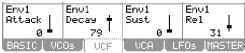
'Attack'
This parameter determines how long an envelope will take to reach maximum level when a pad is struck. Sounds ranging from a slow swelling violin to drum-like attacks are possible by adjusting this parameter. This field also appears on the Basic page. See page 117 for more information.
'Decay'
This parameter determines how long the sound will take to go from the attack phase to the sustain portion of the envelope. This field also appears on the Basic page. See page 117 for more information.
'Sust'
This sets the level at which the filter remains while the pad is being held after completion of the decay phase. See page 117 for more information.
'Rel'
Sets how long a sound will decay when the pad is released. This field also appears on the Basic page. See page 117 for more information.
VCA
VCA stands for Voltage Controlled Amplifier. This page is where in-depth controls for the output volume and the amplifier envelope can be edited. Other Modulations involving volume and panning controls can be found here. To enter the VCA page, do the following:
- From the MAIN screen, select a track that uses a synth program
You can also create a new synth program as detailed in the previous section.
- Press [MODE] and [PAD 6] (PROGRAM)
This will bring you into PROGRAM mode where you can edit different parameters of your program.
| Pam: Senth Pros 061 | ||||
| Program Level 100 | Uel> Amp 100 | Key> Amp 0 | LFO> Amp 0 | |
| Program Pan 50 | Stereo Spread 0 | Key> Pan 0 | LFO> Pan 0 | |
| Env2 Attack ↓ 0 | Env2 Decay ↑ 79 | Env2 Sust ↑ 80 | Env2 Rel ↓ 31 | |
| BASIC UCOs UCF UCA LFOs MASTER | ||||
Note: You can also use the [SYNTH] button as a shortcut to jump to the last Synth program you edited.
- Press the [F4] (VCA) button.
This will display the VCA page. Here, the output levels and amp envelope can be edited. Each parameter can be selected by using the [CURSOR] to select each field and then turning the [DATA] wheel.
- Edit the parameters of the Volume page as desired.
The following parameters are available to be edited.
'Program Level'
Controls the overall volume of the current program. This field also appears on the Basic page. See page 117 for more information.
'Vel>Amp'
Sets how much velocity will affect the volume of the program. The corresponding Q-Link [AFTER] button toggles whether the effect of this modulation will be positive or negative.
'Key>Amp'
Sets the amount that the volume of the program will track the keys. The corresponding Q-Link [AFTER] button toggles whether the effect of this modulation will be positive or negative.
LFO>Amp
The knob sets the amount the selected LFO will affect the volume, creating a tremolo effect. The corresponding Q-Link [AFTER] button toggles whether the effect of this modulation will be positive or negative.
'Program Pan'
This parameter controls where the program's sound will play in the stereo field. 50 is center. 0 is panned hard left, and 100 is panned hard right.
'Stereo Spread'
This parameter sets the stereo position of the individual VCOs. A setting of zero will have all 3 oscillators play panned center. As the value of this parameter increases, VCO1 remains in the center, VCO2 pans further to the left, and VCO3 pans further to the right.
'Key>Pan'
This selects whether keytracking will have an effect on pan. When set to 0, no panning will take place. When set to 100, the highest and lowest notes will be panned across the stereo field. The corresponding Q-Link [AFTER] button toggles whether the effect of this modulation will be positive or negative.
LFO>Pan
The knob sets the amount of effect the LFO will have on panning, creating a Leslie or rotary speaker type effect. The corresponding Q-Link [AFTER] button toggles whether the effect of this modulation will be positive or negative.
ENV2
These parameters control the various aspects of Envelope 2. This envelope affects the overall volume of the program.
'Attack'
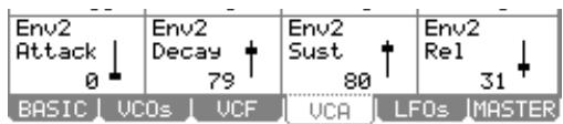
This parameter determines how long an envelope will take to reach maximum level when a pad is struck. Sounds ranging from a slow swelling violin to drum-like attacks are possible by adjusting this parameter. This field also appears on the Basic page. See page 117 for more information.
'Decay'
This parameter determines how long the sound will take to go from the attack phase to the sustain portion of the envelope. This field also appears on the Basic page. See page 117 for more information.
'Sust'
This determines how long a sound will sustain after the decay portion of the envelope finishes. See page 117 for more information.
'Rel'
Sets how long a sound will decay when the pad is released. This field also appears on the Basic page. See page 117 for more information.
LFOs
This page is where the parameters for the LFOs can be edited. The MPC5000 has two LFOs. One is dedicated to vibrato. The other LFO is used for different modulations. To enter the LFOs page, do the following:
- From the MAIN screen, select a track that uses a synth program. You can also create a new synth program as detailed in the previous section.
- Press [MODE] and [PAD 6] (PROGRAM)
This will bring you into PROGRAM mode where you can edit different parameters of your program.
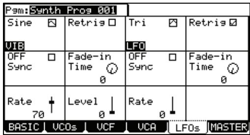
Note: You can also use the [SYNTH] button as a shortcut to jump to the last Synth program you edited.
- Press the [F5] (LFOs) button.
This will display the LFOs page. Here, the various parameters for the Vibrato and the LFO can be edited. Each parameter can be selected by using the [CURSOR] to select each' field and then turning the [DATA] wheel.
- Edit the parameters of the LFOs page as desired.
The Screen is divided in half. The parameters on the left are for Vibrato. The parameters on the right are for the LFO.
'Wave'
This field selects which basic waveform for the LFO and Vibrato.
'Retrig'
This setting determines if the LFO and Vibrato waveforms will run on their own in the background, or be triggered when a key is pressed. With Retrig ON, notes with extreme pitch fluctuations will always start from the original pitch. This is useful for vibrato. With Retrig OFF, modulations will sound more "Natural". This is useful for when the LFO is set to a slow rate, and you want the change to happen over a long time as you play.

'Sync'
Selects whether the LFO will sync to MIDI. When set to YES, the 'Rate' parameter will be hidden, and the sync parameter will display different beat synced rates from 8 whole notes to 1/32 notes. When set to NO, the LFO will run independently from the sequencer.
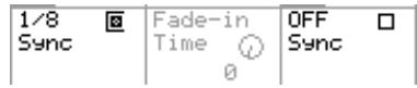
'Fade-in Time'
Increasing this parameter from zero will cause the LFO to increase in amplitude on a curve. This allows the LFO effect to 'fade in', like the parameter's name would suggest.
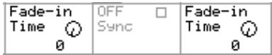
'Rate'
These parameters control the speed of the LFO and Vibrato. When the 'Sync' parameter is set, the 'Rate' controls are hidden.
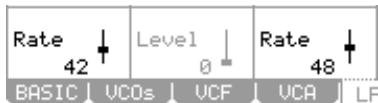
'Level' (Vibrato Only)
This parameter controls the amount of vibrato that is applied to the program.
MASTER
The global aspects of a synth program are accessed in the Master page. To access the Master page, do the following:
- From the MAIN screen, select a track that uses a synth program
You can also create a new synth program as detailed in the previous section.
- Press [MODE] and [PAD 6] (PROGRAM)
This will bring you into PROGRAM mode where you can edit different parameters of your program.
| Pam:Spith Pros 061 | |||
| Poly Trans 0 | Lesato Glide 0 | Random Range 0 | Pitchbend 2 |
| Modu> Uco1 0 | Modu> Filter 0 | Modu> Amp 0 | Modu> Uib 5 |
| Aft> Uco1 0 | Aft> Filter 0 | Aft> Amp 0 | Aft> Uib 2 |
| BASIC UCOs UCF UCA LFOs MASTER | |||
Note: You can also use the [SYNTH] button as a shortcut to jump to the last Synth program you edited.
- Press the [F6] (MASTER) button.
This will display the Master page. Here, global parameters for a synth program can be edited. Each parameter can be selected by using the [CURSOR] to select each field and turning the [DATA] wheel.
- Edit the parameters of the Master page as desired.
The following parameters are available to be edited.
'Voice Mode' (MONO/POLY)
'Voice Mode' selects whether the synth program will play polyphonically or monophonically. Selecting this parameter will toggle between MONO and POLY. When set to MONO, the program will only play one note at a time. This is useful for bass or lead style playing. When set to POLY, many notes can be played at once.
Note: The MPC5000 has 64 notes of polyphony, meaning that it can play up to 64 notes at once.
'Trans'
'Transpose' sets the base pitch of the program in semitones. A program can be transposed up or down to four octaves (48 semitones).
'Legato'
When 'legato' is turned on, playing a pad and pressing another pad will change pitch to the newly pressed pad without retriggering the envelopes. This is useful for lead-style programs.
'Glide'
This selects the Glide time of the program. Glide will lag the change in pitch from one note to another when a second note is played. This parameter selects how long it takes to glide from one note to another. This is useful for lead-type sounds and sound effects when the program is set to MONO. When a program is set to POLY, new notes will glide from the last note released.
'Random Range'
Controls the amount of random detuning for the VCOs. This is good for simulating older, less stable analog style synthesizers. Random Range is useful for fattening up pads, leads, and all sorts of other synth type sounds.
'Pitchbend'
This parameter sets the Pitchbend range in semitones for use with an external MIDI controller's Pitchbend wheel. Up to 12 semitones (one octave) can be set.
'ModW>Vco1'
This parameter selects the degree in which the modwheel will affect the pitch of VCO1. The higher the value, the higher the pitch of VCO1 will increase. The corresponding Q-Link [AFTER] button toggles whether the effect of this modulation will be positive or negative. Modwheel events can be received via MIDI from a keyboard or as control changes from a sequencer.
'ModW>Filter'
This parameter selects the degree in which the modwheel will control the filter. The higher the value, the more open the filter will become. The corresponding Q-Link [AFTER] button toggles whether the effect of this modulation will be positive or negative. Modwheel events can be received via MIDI from a keyboard or as control changes from a sequencer.
'ModW>Amp'
This parameter selects the degree in which the modwheel will control the program volume. The higher the value, the more the modwheel will increase the volume of the program. To get the most out of this parameter, reduce the 'Program Volume' parameter and turn up 'ModW>Amp'. The corresponding Q-Link [AFTER] button toggles whether the effect of this modulation will be positive or negative. Modwheel events can be received via MIDI from a keyboard or as control changes from a sequencer.
'ModW>Vib'
This parameter selects the degree in which the modwheel will control the Vibrato Level. The higher the value, the more the modwheel will increase the program Vibrato. The corresponding Q-Link [AFTER] button toggles whether the effect of this modulation will be positive or negative. Modwheel events can be received via MIDI from a keyboard or as control changes from a sequencer.
'Aft>Vco1'
This parameter selects the degree in which Aftertouch will affect the pitch of VCO1. The higher the value, the higher the pitch of VCO1 will increase. The corresponding Q-Link [AFTER] button toggles whether the effect of this modulation will be positive or negative.
Note: Aftertouch can be received via MIDI controllers, or the MPC5000's pads can also send Aftertouch when playing Synth programs.
'Aft>Filter'
This parameter selects the degree in which Aftertouch will control the filter. The higher the value, the more open the filter will become. The corresponding Q-Link [AFTER] button toggles whether the effect of this modulation will be positive or negative.
'Aft>Amp'
This parameter selects the degree in which Aftertouch will control overall program volume. To get the most out of this parameter, reduce the 'Program Volume' parameter, and turn up 'Aft>Amp'. The higher the value, the more the modwheel will increase the volume of the program. The corresponding Q-Link [AFTER] button toggles whether the effect of this modulation will be positive or negative.
'Aft>Vib'
This parameter selects the degree in which aftertouch will control the Vibrato Level. The higher the value, the more Aftertouch will increase the program Vibrato. The corresponding Q-Link [AFTER] button toggles whether the effect of this modulation will be positive or negative.
Other Program Functions
Pressing the [WINDOW] button in the 'Pgm' field brings up the Program window. In the Program window, you can edit the setting for the selected program.
Changing the program name
- In the 'Pgm' field of the PROGRAM page, select a program that you wish to change the name of.
- Press the [WINDOW] button.
The Program window will open.
- In the 'Program name' field, enter the new name.
For more information for setting the name, see the 'Setting Names' section on Page 18.
- Press [F4] (CLOSE) button.
It closes the window and goes back to PROGRAM mode.
■ Copying a program
You can copy a program to make a new program.
- In the 'Pgm' field in PROGRAM mode, select the program that you wish to copy.
- Press the [WINDOW].
The Program window will be displayed.
- Press [F5] (COPY).
The Copy Program window will be displayed.
- In the 'New name' field, set the name for the new program.
For more information regarding setting the name, see the 'Setting Names' section on Page 18.
- Press [F3] (DO IT).
Copying the program will start. To cancel the operation, press [F4] (CANCEL) instead.
- Deleting a program
You can remove a program from the memory of the MPC5000.
-
In the 'Pgm' field in PROGRAM mode, select the program that you wish to delete.
-
Press the [WINDOW] button.
The Program window will be displayed.
- Press [F2] (DELETE) button
The Delete Program window will be displayed.
- Press [F5] (DO IT) button.
This deletes the selected program.
- Deleting all programs
You can delete all the program data in the memory at the same time.
- In the PROGRAM mode, select the 'Pgm' field and press the [WINDOW] button.
The Program window will be displayed.
- Press [F2] (DELETE) button.
The Delete Program window will be displayed.
- Press [F3] (ALL PG) button.
The Delete ALL Programs window will be displayed.
- Press [F5] (DO IT) button.
This deletes all the programs.
Setting a Program Change Number
You can switch the programs assigned to a track within the sequence by setting the program change numbers in each program. You do not have to set the program change numbers if you do not need to switch the programs. To switch the programs, program change events are used. You can enter these events in the STEP EDIT mode. For more information about entering the program change events, see the 'STEP EDIT Mode' chapter on page 43.
- In the 'Pgm' field of the PROGRAM mode, press the [WINDOW] button.
The Program window will be displayed.
- Select the 'MIDI program change' field and set the program change number.
If a track has a program change event with the same number set in this field, the MPC5000 switches the program at the event while playing back the sequence. If you do not wish to switch the program during the playback, set this field to OFF.
■Assigning MIDI Notes to Pads in a Sample Program
The performance data you made by hitting the MPC5000's pads is sent to the internal sampler and sequencer section directly. You can also send the data as a MIDI signal at the same time. The performance data will be sent as MIDI note information. To do so, you need to determine which MIDI note to send out when you hit each pad.
Also, when you load sequence data created on external sequencer and saved as a smf or .mid file to the MPC5000 and play the internal sampler section, you have to determine which pad to play by the MIDI note data in the sequence. Any midi note number (0-127) can be assigned.
In this section, you will learn how to assign MIDI notes to the pads of a Sample program.
- In the PROGRAM mode, press the [F3] (NOTE) button.
The NOTE page will be displayed.
- Select the desired pad by hitting it.
The note number of the selected pad will be highlighted.
- Select the note number with the [DATA] wheel.
In the upper right corner of the screen, the MIDI GM standard name of the drum, which represents the selected note number, is displayed. To reset the setting to the default, press the [F6] (RESET) button. All the notes assigned to the pads will be reset to the default setting.
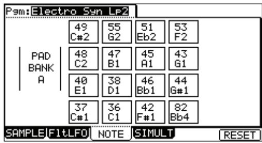
Changing the Default Note Number Assignment
Normally, when you hit a pad, the MPC5000 will output the MIDI note data assigned to the pad in the program. However, when the selected track does not have any program assigned, hitting a pad sends out the default MIDI note number instead of the number set in the program. When you create a new program, this setting will be used as the default setting.
- Press the [MODE] button and then the [PAD 8] (MIDI/SYNC).
The MIDI/SYNC page is displayed.
- Press the [F3] (NOTE) button.
The NOTE page will be displayed.
- Select the desired pad by hitting it.
The note number of the selected pad will be highlighted.
- Select the note number with the [DATA] wheel.
In the upper right corner of the screen, the MIDl GM standard name of the drum, which represents the selected note number, is displayed.
To reset the setting to the default, press the [F6] (RESET) button. All the notes assigned to the pads will be reset to the default setting.
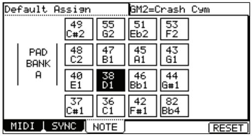
Chapter 14: Arpeggiator
The MPC5000's Arpeggiator is a powerful new feature that lets you play repeating patterns in perfect time, much like Note Repeat, simply by holding down one or more notes. This is very useful feature because it allows you to play extremely complex (or repetitive) passages of music with ease.
Editing the Arpeggiator
To use the Arpeggiator, try the following:
- From the MAIN page, select a track you wish to use with the Arpeggiator.
Each track in a sequence can have an arpeggior (or 'Arp' for short) assigned to it. Arpeggiators work best with synth type programs, or external MIDI devices, but using one on a drum program can yield unusual and exciting rhythms as well.
- Press either [MODE] + [PAD 10] or the [ARPEGGIATOR] button.
This will open the ARPEGGIATOR page as shown on the right. Note that the current track, and the current program are displayed in the 'Track' and 'Program' fields, respectively.
- Press the [ARP ON/OFF] button to turn on the Arpeggiator.
- Press and hold down three or four pads, or hold a few notes on your external MIDI controller.
The MPC5000 will play the notes you've selected in a pattern defined by the Arpeggiator settings.
- Adjust the 'Arp Pattern' field as desired to vary the pattern.
The following settings are available:
Up
The notes being held will move upward from lowest note to highest note.
For example, if you hold down the notes C3, E3, and G3, the arpeggiator would play the following repeating pattern:
C3,E3,G3
While holding down the above, if you were to add a D4, the MPC would then play the following.
C3,E3,G3,D4
Down
The notes being held will move downward from highest note to lowest note.
For example, if you hold down the notes C3, E3, and G3, the arpeggiator would play the following repeating pattern:
G3,E3,C3
While holding down the above, if you were to add a D4, the MPC would then play the following.
D4,G3,E3,C3
Inclusive
The notes being held will move upward then downward from lowest note to highest note then from highest to lowest, playing the lowest and highest note twice.
For example, if you hold down the notes C3, E3, and G3, the arpeggiator would play the following repeating pattern:
C3,E3,G3,G3,E3,C3
While holding down the above, if you were to add a D4, the MPC would then play the following.
C3,E3,G3,D4,D4,G3,E3,C3
Exclusive
The notes being held will move upward then downward from lowest note to highest note then from highest to lowest, without repeating the lowest and highest note.
For example, if you hold down the notes C3, E3, and G3, the arpeggiator would play the following repeating pattern:
C3,E3,G3,E3
While holding down the above, if you were to add a D4, the MPC would then play the following.
C3,E3,G3,D4,G3,E3
Random
The notes being held will play in a completely random pattern.
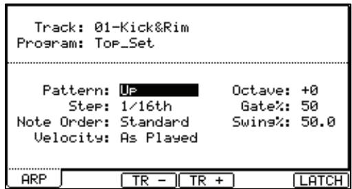
- Set the desired octave range in the 'Octave' field.
Up to three octaves up or down can be set. For example, if the Arpeggiator is set to an 'up' pattern, and you have the 'Octave' field set to 1, if you held down the notes C3, E3 and G3, the arpeggiator would play the following repeating pattern:
C3,E3,G3,C4,E4,G4
The original octave is always played first. To illustrate this, building on the example above, if the pattern was set to 'down', then the following pattern would play:
G3,E3,C3,G4,E4,C4
- Adjust the 'Step' field to set at what increments the Arpeggiator will play.
The following steps are available.
1/8, 1/8(3), 1/16, 1/16(3), 1/32, 1/32(3), 1/64, 1/64(3)
Note: Unlike Note Repeat, this is independent of Timing Correct, allowing for Note Repeat and the Arpeggiator to play different patterns independently.
- Adjust the 'Gate%' field to set how the Arpeggiator will play the notes.
This parameter determines how long each note will play, represented by a percentage of the 'Step' time. In other words, if 'Step' is set to 16th notes, and 'Gate' is set to 50% , each note will be played for half the length of a 16th note.
- Adjust the 'Note Order' field as desired.
The following options are available.
Standard
The Arpeggiator will play the notes in order ascending or descending, depending on the 'Arp Pattern'.
As Played
The Arpeggiator will play the notes in the order they were played.
- Adjust the 'Swing%' field as desired.
Like Timing Correct, this will delay certain notes of the Arpeggiator pattern to create a shuffled feel.
Note: Unlike Note Repeat, this is independent of Timing Correct, allowing for Note Repeat and the Arpeggiator to play different patterns independently.
- Adjust the 'Velocity' parameter as desired.
This allows the velocity of each note played by the Arpeggiator to have their velocities set to anywhere from 1-127, or set to the velocity they were played.
Latching the Arpeggiator
'Latching' is a method of letting your arpeggiatior play without having to hold down any notes (or trigger sources). The Arpeggiatior will keep playing until 'latch' is turned off, or the [STOP] button is pressed.
To use latching, do the following:
-
From the [MAIN] page, select a track you wish to use the Arpeggiator with.
-
Press the [ARPEGGIATOR] button.
-
Press the [F6] (Latch) button.
This will turn on the Latch function of the Arpeggiator.
- Press and release a few pads, or play some keys on your controller keyboard.
For example, if you press and release the following keys: C3, E3, G3
These notes will continue to play after they are released.
- Press and release another key or pad.
Pressing another key, D4 for example, would stop the previous 3 notes and start playing D4 only.
- Next, press and release the keys or pads pressed in step 4.
These will now play again in place of D4
- Now, press the three keys or pads pressed in step 4 and add another.
For example, if C3, E3, and G3 are playing, and you press these three keys again along with D4, all four would now play.
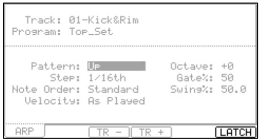
Try experimenting further with the Arpeggiator, along with latching. You will find the Arpeggiator a powerful addition to the live performance aspect of the MPC5000.
Using the Arpeggiator with Pre-Recorded Tracks
The Arpeggiator can also be used with previously recorded sequencer tracks. To do so, do the following:
- Select a track in the current sequence with previously recorded data.
For best results, use a synth or MIDI program rather than a Drum type program. - Press the [ARP ON/OFF] button.
- The recorded data on the selected track will now play in an arpeggio pattern.
Chapter 15: Effects
In this section, you will learn how to select and edit effects. The MPC5000 has four stereo effect busses and each buss can have two different effects assigned to it. Busses can be combined in pairs to allow a total of four effects per buss. Additionally, a master EQ and compressor are available for the Stereo outputs. Each pad can be routed to one of the four effects busses, and each effect buss can be routed independently to any of the available outputs.
Note: All effects settings will be saved with the .ALL file, which is created when you save the data by selecting SAVE ALL SEQS & SONGS.
Applying Effects to a Pad
In this section will demonstrate how to assign an effect to a pad. Here, let's apply REVERB to an individual pad.
- Press the [MODE] and [PAD 11] (EFFECTS).
The EFFECTS page will be displayed. In this page, the signal paths of each effects buss are displayed. Two effects can be assigned in series per buss. Busses 1 and 2 are displayed on the first page as FX1 and FX2. Press [F2] (BUS3-4) to view busses 3 and 4. Busses 1 and 2, and busses 3 and 4 can be routed together to allow up to four effects per bus.
- Press the [F1] (BUS1-2) button.
This will make sure that busses 1 and 2 are displayed.
- Move the cursor to the first effects block in FX1.
Each effect slot is displayed as a block. When the effect is bypassed, the block will appear above the signal path line. Each block can be selected using the [CURSOR] buttons.
- Press the [WINDOW] button or turn the [DATA] wheel.
This will display the EFFECT EDIT window as shown on the right. This is where different aspects of the effect can be edited. For more information on editing effects, see page 135.
- In the 'FX 1 Block A' field, scroll with the [DATA] wheel.
This will open the EFFECT SELECT window, where a list of effects is displayed.
- Choose 'Reverb Small' from the list and press [F5] (SELECT).
This brings you back to the EFFECT EDIT window.
-
Press [F4] (CLOSE) to exit the EFFECT EDIT window.
-
Press [F6] (GO2MIX)
This is a shortcut to take you into MIXER mode. You can also get to MIXER mode by Pressing the [MODE] and [PAD 8] (MIXER).
- Press the [F1] (PrgMix) button.
The PAD MIX page will be displayed.
- Hit the desired pad.
This pad will be selected and its display will be highlighted.
- Select the FX column.
Here, the different effect busses can be selected. The following are available:
一
No effect will be applied to the pad.
1-4
The buss effect corresponding to the selected number will be applied to the pad.
For this example, select 1.
- Select the Send column and adjust the Effect Send level.
This controls the amount of effect will be heard when the pad is struck. For our example, set the knob to about 50% .
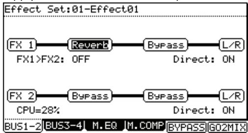
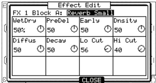
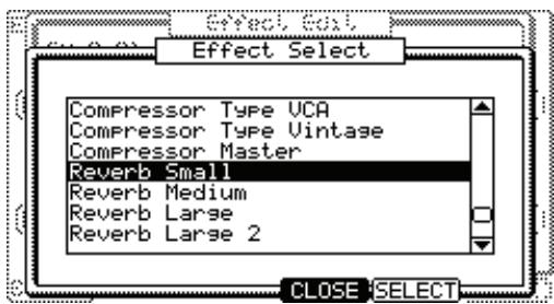
- Play the pad.
The effected sound will play from the [STEREO OUT].
Tip: You can apply the effect to several pads. The effect of the FX 1 is applied to all the pads whose FX SEND are set to 1 in the FX SEND page of the MIXER mode.
Tip: You can adjust the send level column to adjust the amount of the reverb for each pad.
Tip: You can edit the effects in detail. For more information about detailed editing of each effect, see the 'Editing Effects' section on page 135.
Like FX 1, you can use the effects of the FX 2-4 by setting the 'FX' column to the desired buss and adjusting the Send Level in the SEND column.
Buss Effects vs. Insert Effects
Some effects, such as reverbs and delays, are best used as a buss effect, controlling the amount of signal individual sounds are sent. This allows for different sources to use the same effect with different send levels.
See the signal flow diagram on the right for an example of a buss effect
Some effects work best when 100% of the signal is sent to the effect, without mixing any dry signal. These are called Insert effects, and they include compressors, limiters, filters, Autopan effects and parametric EQs.
See the signal flow diagram on the right for an example of an insert effect
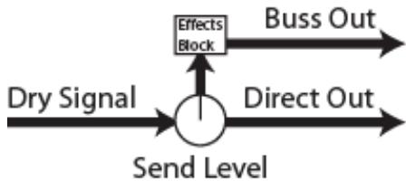

Setting an Effect as an Insert
Here, we will show how to set an effect buss as an insert. In this example, we will set an Autopan to FX2.
- Press the [MODE] and [PAD 11] (EFFECTS), then Press the [F1] (BUS1-2) button.
- Select the first effect block of FX2.
- Press the [WINDOW] button or turn the [DATA] wheel. This will display the EFFECT EDIT window.
- In the 'FX 2 Block 1' field, scroll with the [DATA] wheel to choose AUTOPAN and press [F5] (SELECT). This brings you back to the EFFECT EDIT window.
- Press [F4] (CLOSE) to exit the EFFECT EDIT window.
- Select the 'DIRECT' field. The following selections are available
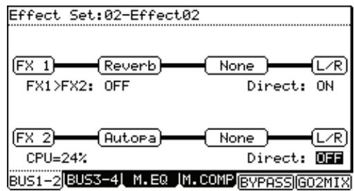
ON
The dry signal of the source is sent to the output along with the effect
OFF
The dry signal is not sent to the output. 100% of the source is sent to the effect.
For our example, set this field to OFF.
- Press [F6] (GO2MIX)
This is a shortcut to take you into MIXER mode. You can also get to MIXER mode by Pressing the [MODE] and [PAD 8] (MIXER).
- Press the [F1] (PrgMix) button.
The PAD MIX page will be displayed.
- Hit the desired pad.
This pad will be selected and its display will be highlighted.
- Select the FX column and set the FX to 2.
This will assign the desired pad to effects buss 2. Note that the Send Column's control for this pad has now disappeared. This is because as the signal diagrams on page 134 show, when DIRECT is set to OFF, the effects buss acts as an insert, and 100% of the dry signal is automatically sent to the effect.
Adding additional Effects to the Effects Buss
Each effects buss can have two effects assigned to it. This can allow for extremely complex, wild sounding effects. As an example, continuing from our example on page 133, let's add a delay to the Reverb on Buss 1.
- Press the [MODE] and [PAD 11] (EFFECTS), then Press the [F1] (BUS1-2) button.
- Select the second effect block of FX2.
- Press the [WINDOW] button or turn the [DATA] wheel.
This will display the EFFECT EDIT window.
- In the 'FX 1 Block 2' field, scroll with the [DATA] wheel to choose delay and press [F5]_(SELECT).
This brings you back to the EFFECT EDIT window. - Press [F4] (CLOSE) to exit the EFFECT EDIT window.
- Hit a pad assigned to buss 1.
Notice that now there is a delay effect added to the reverb effect.
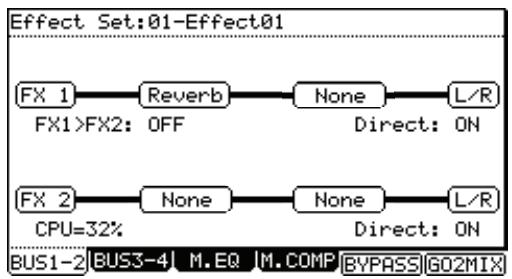
Tip: Setting the send level high, or setting this busses 'direct' field to OFF, and adjusting the relationship of each effect to one another using each effect's 'Wet/Dry' parameter can allow for even greater flexibility. For more information on editing each effect individually, see the section titled 'Editing Effects' on page 135.
Effect Buss Chaining
Effect chaining allows for the output of one buss to be routed into the input of another. Buss 1 can be routed through buss 2, and buss 3 can be routed to buss 4. This allows a program to be able to use up to four effects in series.
All Inputs sent to FX1 are first routed through FX1, then through FX2. Inputs routed to FX2 will be sent through FX2 only.
To turn on Effects Chaining, do the following:
- Press [MODE] + [PAD11] (EFFECTS) to enter Effects Mode.
- Select the FX1>FX2 field.
- Change the FX1>FX2 field to "ON" by turning the [DATA] wheel.
FX1 will be routed to the input of FX2.

About CPU Usage
The MPC5000 has a dedicated processor for effects. Each effect on the MPC5000 uses a certain percentage of this CPU's power. Some effects, such as flangers, choruses etc, use very little power. Others, like reverbs and delays take substantially more power. When adding effects, it's a good idea to keep watch of the CPU meter.
Editing Effects
In this section, you will learn how to edit effects. When you scroll with the [DATA] wheel on an effects block, or press the [WINDOW] button while an effects block is selected, the EFFECTS EDIT page will be displayed. Here, you can edit the effects selected in each effect block.
Tip: If you press the [F5] (BYPASS) button while an effects module is selected, you can turn off this effect temporally. This is useful to compare the effected sound and the original sound.
Effect List
Below is a brief overview of each effect type.
Flanger / Flanger Sync
Flanger is an effect that uses a delay line to emulate the classic warbling effect produced using two analog tape machines together. This effect is best used as an insert by turning 'DIRECT' off. See page 134 for more on this.
| WetDry | Controls the ratio of unprocessed and processed signal. At 100, the signal heard will be 100% effected. |
| Rate | Controls the speed of the flanger effect. |
| Feedback | Controls how much of the output signal is fed back to the input, creating a more pronounced effect. Both positive and negative feedback is available. |
| Width | Controls how much of the frequency range of the incoming signal is effected. |
Chorus 4-Voice / 2-Voice
A Chorus effect uses an LFO to modulate the pitch of the input signal, which is then added back to the dry signal. In small doses this will create the illusion of multiple voices playing at once. Turn up the Feedback and Depth for more pronounced "shimmering" and "watery" sounds.
This effect is best used as an insert by turning 'DIRECT' off. See page 134 for more on this.
| WetDry | Controls the ratio of unprocessed and processed signal. At 100, the signal heard will be 100% effected. |
| Amount | This adjusts the magnitude of the LFO modulation. |
| Width | Controls how much of the frequency range of the incoming signal is effected. |
| Speed | Controls the speed of the LFO. |
Autopan / Autopan BeatSync
This effect uses an LFO to move the incoming signal back and forth across the stereo field, creating a rotating effect.
This effect is best used as an insert by turning 'DIRECT' off. See page 134 for more on this.
| WetDry | Controls the ratio of unprocessed and processed signal. At 100, the signal heard will be 100% effected. |
| Rate | Controls the panning speed. |
Tremolo / Tremolo BeatSync
This effect uses an LFO to raise and lower the volume of the incoming signal. Depending on the LFO shape, this can vary in sound from a circular waving effect, to a stuttering "ON / OFF" effect.
This effect is best used as an insert by turning 'DIRECT' off. See page 134 for more on this.
| WetDry | Controls the ratio of unprocessed and processed signal. At 100, the signal heard will be 100% effected. |
| Rate | Controls the speed of the LFO. |
| Shape | Controls the shape of the LFO, varying between a TRIANGLE (0) and a SQUARE (100) wave. |
Phaser 1 / Phaser 2 / Phaser Sync
The Phaser is a classic effect that is created by ganging multiple all-pass filter stages to create "notches," or sharp dips in the frequency spectrum. The frequencies of these all-pass filters are usually modulated by an LFO to create a dramatic sweeping sound.
This effect is best used as an insert by turning 'DIRECT' off. See page 134 for more on this.
| WetDry (1/2/Sync) | Controls the ratio of unprocessed and processed signal. At 100, the signal heard will be 100% effected. |
| Rate (1/2/Sync) | Controls the speed of the LFO. |
| Depth (2/Sync) | Controls the amount of the phaser effect. |
| Reso (2/Sync) | Controls the resonant peaks of the notch filters. |
| Stages (2/Sync) | This selects how many all-pass filter stages, and thus notches are used. |
LP / HP Filter Sweep / Sync
This effect is a filter, with the frequency of the filter modulated by an LFO. Both Highpass and Lowpass filters are available.
| WetDry | Controls the ratio of unprocessed and processed signal. At 100, the signal heard will be 100% effected. |
| Rate | Controls the speed of the LFO. |
| MOD Amt | Controls the amount the filter cutoff is modulated by the LFO. |
| Cutoff | Controls the frequency at which the filter will affect the incoming signal. |
| Reso | Controls the emphasis of the frequency at the cutoff point. |
| Pole Select | Selects how many poles the selected filter will be. A 2 pole filter will have a milder effect, where an 8 pole filter will have a more extreme effect. |
Autowah
This effect is a lowpass filter modulated by an envelope. The envelope is triggered by the incoming audio signal, and the amount of effect the envelope has on the cutoff frequency can be controlled by the incoming audio signal's amplitude. This yields a classic funky "wah wah" type sound.
| WetDry | Controls the ratio of unprocessed and processed signal. At 100, the signal heard will be 100% effected. |
| Cutoff | Controls the frequency at which the filter will affect the incoming signal. |
| Res | Controls the emphasis of the frequency at the cutoff point. |
| Attack | Sets the amount of time the envelope takes to reach its maximum value. Slower attacks will yield a string-like attack. Faster attack times will give you a more quick, punchy type sound. |
| Rels | This sets how long the envelope takes to go from maximum value to zero. |
| Sens | Controls how dramatically the autowah effect will respond to volume changes. Set this to a lower value for louder sources, and a higher value for quieter sources. |
HP / LP Filter
This effect is a static filter without modulation.
| Freq | Controls the frequency at which the filter will affect the incoming signal. |
| Res | Controls the emphasis of the frequency at the cutoff point. |
HP / LP Shelving Filter
This filter differs from the standard filter type in that all frequencies affected by the cutoff point are attenuated equally.
| Freq | Controls the frequency at which the filter will affect the incoming signal. |
| Res | Controls the emphasis of the frequency at the cutoff point. |
| Gain | Adjusts the level of the output signal. |
2-Band, 2-shelf PEQ
This effect is a combination of a two-band parametric equalizer and two shelving filters.
This effect is best used as an insert by turning 'DIRECT' off. See page 134 for more on this.
| LowFreq | Sets the frequency at which the low shelf will start to affect the incoming signal. |
| LowGain | Sets the volume amount that the low shelf will attenuate or boost the incoming signal. |
| HiFreq | Sets the frequency at which the high shelf will start to affect the incoming signal. |
| HiGain | Sets the volume amount that the high shelf will attenuate or boost the incoming signal. |
| Freq1 | Sets the frequency of the first band of the parametric EQ. |
| Gain1 | Sets the amount of attenuation or boost that will be applied around the frequency selected with Freq1. |
| Q1 | This parameter sets the width of the band that is being affected by Freq1. |
| Freq2 | Sets the frequency of the second band of the parametric EQ. |
| Gain2 | Sets the amount of attenuation or boost that will be applied around the frequency selected with Freq2. |
| Q2 | This parameter sets the width of the band that is being affected by Freq2. |
4-Band PEQ
This effect is a powerful four band parametric equalizer, with four independent EQ points.
This effect is best used as an insert by turning 'DIRECT' off. See page 134 for more on this.
| Freq1 | Sets the frequency of the first band of the parametric EQ. |
| Freq2 | Sets the frequency of the second band of the parametric EQ. |
| Freq3 | Sets the frequency of the third band of the parametric EQ. |
| Freq4 | Sets the frequency of the fourth band of the parametric EQ. |
| Q1 | This parameter sets the width of the band that is being affected by Freq1. |
| Q2 | This parameter sets the width of the band that is being affected by Freq2. |
| Q3 | This parameter sets the width of the band that is being affected by Freq3. |
| Q4 | This parameter sets the width of the band that is being affected by Freq4. |
| Gain1 | Sets the amount of attenuation or boost that will be applied around the frequency selected with Freq1. |
| Gain2 | Sets the amount of attenuation or boost that will be applied around the frequency selected with Freq2. |
| Gain3 | Sets the amount of attenuation or boost that will be applied around the frequency selected with Freq3. |
| Gain4 | Sets the amount of attenuation or boost that will be applied around the frequency selected with Freq4. |
Delay Mono / Delay Mono BeatSync
Delay takes the original signal, waits a specified period of time, and then plays it back, over and over.
Mono delay sums the signal input to mono before applying the delay effect. The result is a less complex but more "focused" sound.
| WetDry | Controls the ratio of unprocessed and processed signal. At 100, the signal heard will be 100% effect. |
| Time | Sets the amount of time between the original signal, and the delayed signal. |
| Feedback | Sets the amount of times the delayed signal will be repeated. This control is capable of self-oscillation at maximum value. |
| Damping | Cuts off the high frequencies of the delayed signal, creating a darker sound. |
Delay Stereo / Delay Stereo BeatSync
Stereo delay operates similarly to Mono delay only in true stereo. The maximum delay time is half that available to Mono delay.
| WetDry | Controls the ratio of unprocessed and processed signal. At 100, the signal heard will be 100% effected. |
| Time | Sets the amount of time between the original signal, and the delayed signal. |
| Feedbk | Sets the amount of times the delayed signal will be repeated. This control is capable of self-oscillation at maximum value. |
| Damping | Cuts off the high frequencies of the delayed signal, creating a darker sound. |
Delay LP /HP
The LP and HP Delay is identical to the Mono Delay, except instead of using the damping control, a resonant filter is used.
| WetDry | Controls the ratio of unprocessed and processed signal. At 100, the signal heard will be 100% effected. |
| Time | Sets the amount of time between the original signal, and the delayed signal. |
| Feedbk | Sets the amount of times the delayed signal will be repeated. This control is capable of self-oscillation at maximum value. |
| Cutoff | Controls the frequency at which the filter will affect the incoming signal. |
| Res | Controls the emphasis of the frequency at the cutoff point. |
Delay Analog / Delay Analog BeatSync
Analog Delay is similar to Mono Delay, except that it's designed to sound like the unique voicings of an analog style "Bucket Brigade" style delay. This delay has a unique character to it, generally warming up the sound by adding subtle inaccuracies in phase and timing.
| WetDry | Controls the ratio of unprocessed and processed signal. At 100, the signal heard will be 100% effected. |
| Time | Sets the amount of time between the original signal, and the delayed signal. |
| Feedbk | Sets the amount of times the delayed signal will be repeated. This control is capable of self-oscillation at maximum value. |
Delay Tape BeatSync
Tape Delay is a system that uses an analog tape and a series of tape heads to produce an echo effect. The original signal is written to the tape, and then reread by the heads. This delay type yields a very distinct echo sound, often heard in Reggae and Dub style music, as well as on guitar.
| WetDry | Controls the ratio of unprocessed and processed signal. At 100, the signal heard will be 100% effected. |
| Time | Sets the amount of time between the original signal, and the delayed signal from the first head. |
| Feedbk | Sets the amount of times the delayed signal will be repeated. This control is capable of self-oscillation at maximum value. |
| Ramp | Ramp time is the time it takes to change tempo.. This is like motor inertia. At max it takes a long time, and the tape stretch effect is heard most. At minimum, the motor's speed is instant. |
| Head1 - 4 | Sets the volume of each tape head. Careful! Analog Tape Delays can feedback onto themselves when the heads volumes and feedbk controls are turned up. |
| Tone | Controls how dark the sound will be as the echo decays. At 100, this control has no effect. |
| Spread | Controls the relational distance between each tape head. |
| W+F | ‘Wow and Flutter’. This parameter sets the amount of inaccuracies in the sound produced by each tape head. This can be used to simulate an older tape, or more vintage tape machines. |
Delay Ping Pong
This delay is a mono delay which can be set to different delay times for the left and right sides of the stereo field.
| WetDry | Controls the ratio of unprocessed and processed signal. At 100, the signal heard will be 100% effected. |
| Time L | Sets the amount of time between the original signal, and the delayed signal on the left side. |
| Time R | Sets the amount of time between the original signal, and the delayed signal on the right side. |
| Feedbk | Sets the amount of times the delayed signal will be repeated. This control is capable of self-oscillation at maximum value. |
| Damping | Cuts off the high frequencies of the delayed signal, creating a darker sound. |
Delay Multi-Tap
This delay is a mono delay which has three different signal generations that can be panned across the stereo field and independently time controlled.
| WetDry | Controls the ratio of unprocessed and processed signal. At 100, the signal heard will be 100% effected. |
| Time 1 | Sets the amount of time between the original signal, and the delayed signal of tap 1. |
| Time 2 | Sets the amount of time between the original signal, and the delayed signal of tap 2. |
| Time 3 | Sets the amount of time between the original signal, and the delayed signal of tap 3. |
| Feedbk | Sets the amount of times the delayed signal will be repeated. This control is capable of self-oscillation at maximum value. |
| Pan 1 | Controls the stereo position of tap 1. |
| Pan 2 | Controls the stereo position of tap 2. |
| Pan 3 | Controls the stereo position of tap 3. |
| Damping | Cuts off the high frequencies of the delayed signal, creating a darker sound. |
| Gain 1 | Controls the volume level of tap 1. |
| Gain 2 | Controls the volume level of tap 2. |
| Gain 3 | Controls the volume level of tap 3. |
Distortion Fuzz
This popular effect uses extreme hard clipping. This clipping at extreme settings can turn a standard waveform into a square wave, producing an almost "chainsaw" effect.
| WetDry | Controls the ratio of unprocessed and processed signal. At 100, the signal heard will be 100% effected. |
| Drive | Controls the intensity of the distortion effect. |
| Tone | An overall tone shaper to either boost high frequencies, and attenuate lows, or boost low frequencies and attenuate highs. |
| Output | Controls the overall output of the distortion. |
Distortion Amp
This effect is designed to sound like a tube amplifier at louder volumes, producing a wider range distortion than your typical fuzz style distortion.
| WetDry | Controls the ratio of unprocessed and processed signal. At 100, the signal heard will be 100% effected. |
| Drive | Controls the intensity of the distortion effect. |
| Tone | An overall tone shaper to either boost high frequencies, and attenuate lows, or boost low frequencies and attenuate highs. |
| Output | Controls the overall output of the distortion. |
Distortion Overdrive
This distortion is designed to sound like an amplifier mildly distorting at medium volumes. It is the mellowest distortion type available.
| WetDry | Controls the ratio of unprocessed and processed signal. At 100, the signal heard will be 100% effected. |
| Drive | Controls the intensity of the distortion effect. |
| Tone | An overall tone shaper to either boost high frequencies, and attenuate lows, or boost low frequencies and attenuate highs. |
| Output | Controls the overall output of the distortion. |
Distortion Custom
This effect is a highly customized distortion, capable of a wide range of useable sounds.
| WetDry | Controls the ratio of unprocessed and processed signal. At 100, the signal heard will be 100% effected. |
| Drive | Controls the intensity of the distortion effect. |
| +Soft | Controls the curve of the clipping above the waveform zero crossing. |
| +Clip | Controls the amount of clipping applied to the waveform above the zero crossing. |
| -Soft | Controls the curve of the clipping below the waveform zero crossing. |
| -Clip | Controls the amount of clipping applied to the waveform below the zero crossing. |
| Low | Selects how much the low frequencies of the signal will be affected by the distortion. |
| Mid | Selects how much the mid frequencies of the signal will be affected by the distortion. |
| High | Selects how much the high frequencies of the signal will be affected by the distortion. |
| Output | Controls the overall output of the distortion. |
Distortion Grimy
This is a unique distortion effect that distorts a range of frequencies in a variably selectable band.
| WetDry | Controls the ratio of unprocessed and processed signal. At 100, the signal heard will be 100% effected. |
| Drive | Controls the intensity of the distortion effect. |
| Grime | Controls the softness and asymmetry of the distortion curve. More makes it a harder clip. |
| Center | Selects the center frequency of the effected band. |
| Width | Selects the width of the effected band. |
| Res | Sets the amount of emphasis placed on the effected band. |
| Output | Controls the overall output of the distortion. |
Compressor Type Opto
A compressor is an effect that changes the dynamic range of a signal by automatically reducing gain. The Opto Compressor is modeled after a vintage compressor that uses a small light to reduce the overall volume of the input signal. This technique is usually associated with a soft and very musical attack and release.
This effect is best used as an insert by turning 'DIRECT' off. See page 134 for more on this.
| WetDry | Controls the ratio of unprocessed and processed signal. At 100, the signal heard will be 100% effected. |
| Input | Sets the volume of the incoming signal. |
| Attack | Sets how soon the compressor will start functioning after the threshold has been reached. |
| Rels | Sets how soon the compressor will stop functioning after the signal drops below threshold. |
| Thresh | Sets the level at which the compressor will start functioning. |
| Ratio | This sets how much compression will affect the volume of the incoming signal. For instance, with a ratio of 4:1, the incoming signal would have to increase by four decibels in order to increase 1 decibel at the output. |
| Knee | This sets whether the compression effect will be hard or soft. A ‘soft knee’ response will gradually slope to its maximum setting, and a ‘hard knee’ response will respond much quicker. |
| Output | This sets the volume of the output signal. |
Compressor Type VCA
This compressor is more modern sounding, with a more transparent effect. A VCA Compressor tends to have quicker attack and release times than an Opto Compressor.
| WetDry | Controls the ratio of unprocessed and processed signal. At 100, the signal heard will be 100% effected. |
| Input | Sets the volume of the incoming signal. |
| Attack | Sets how soon the compressor will start functioning after the threshold has been reached. |
| Rels | Sets how soon the compressor will stop functioning after the signal drops below threshold. |
| Thresh | Sets the level at which the compressor will start functioning. |
| Ratio | This sets how much compression will affect the volume of the incoming signal. For instance, with a ratio of 4:1, the incoming signal would have to increase by four decibels in order to increase 1 decibel at the output. |
| Knee | This sets whether the compression effect will be hard or soft. A ‘soft knee’ response will gradually slope to its maximum setting, and a ‘hard knee’ response will respond much quicker. |
| Output | This sets the volume of the output signal. |
Compressor Type Vintage
This compressor has a sound similar to the classic tube compressors, complete with gentle, yet pumping curves, and slight tube saturation.
| WetDry | Controls the ratio of unprocessed and processed signal. At 100, the signal heard will be 100% effected. |
| Input | Sets the volume of the incoming signal. |
| Attack | Sets how soon the compressor will start functioning after the threshold has been reached. |
| Rels | Sets how soon the compressor will stop functioning after the signal drops below threshold. |
| Thresh | Sets the level at which the compressor will start functioning. |
| Ratio | This sets how much compression will affect the volume of the incoming signal. For instance, with a ratio of 4:1, the incoming signal would have to increase by four decibels in order to increase 1 decibel at the output. |
| Knee | This sets whether the compression effect will be hard or soft. A 'soft knee' response will gradually slope to its maximum setting, and a 'hard knee' response will respond much quicker. |
| Output | This sets the volume of the output signal. |
Compressor Master
This is the most transparent compressor, able to perform substantial volume adjustments without artifacts.
| WetDry | Controls the ratio of unprocessed and processed signal. At 100, the signal heard will be 100% effects. |
| Attack | Sets how soon the compressor will start functioning after the threshold has been reached. |
| Rels | Sets how soon the compressor will stop functioning after the signal drops below threshold. |
| Thresh | Sets the level at which the compressor will start functioning. |
| Ratio | This sets how much compression will affect the volume of the incoming signal. For instance, with a ratio of 4:1, the incoming signal would have to increase by four decibels in order to increase 1 decibel at the output. |
| Oldskool | This parameter downsamples the output to 12 bits in order to emulate the output sound of many vintage samplers. |
| Output | This sets the volume of the output signal. |
Reverb Small
This is a spatial effect designed to sound as if the input is being played in a small room.
| WetDry | Controls the ratio of unprocessed and processed signal. At 100, the signal heard will be 100% effected. |
| PreDel | Predelay sets the amount time before the sound enters the reverb "room". |
| Early | Sets the amount of initial reflection the sound will have. |
| Dnsity | This setting controls the amount of individual reverberations that will be contained in the affected output. |
| Diffuse | Controls how much the reverberations will increase as the sound decays. |
| Decay | Sets how long the reverb effect will take to stop. |
| Lo Cut | Removes low frequencies from the affected output. |
| Hi Cut | Removes high frequencies from the affected output. |
Reverb Medium
This is a spatial effect designed to sound as if the input is being played in a medium room.
| WetDry | Controls the ratio of unprocessed and processed signal. At 100, the signal heard will be 100% effected. |
| PreDel | Predelay sets the amount time before the sound enters the reverb "room". |
| Early | Sets the amount of initial reflection the sound will have. |
| Dnsity | This setting controls the amount of individual reverberations that will be contained in the affected output. |
| Diffus | Controls how much the reverberations will increase as the sound decays. |
| Decay | Sets how long the reverb effect will take to stop. |
| Lo Cut | Removes low frequencies from the affected output. |
| Hi Cut | Removes high frequencies from the affected output. |
Reverb Large
This is a spatial effect designed to sound as if the input is being played in a large hall.
| WetDry | Controls the ratio of unprocessed and processed signal. At 100, the signal heard will be 100% effected. |
| PreDel | Predelay sets the amount time before the sound enters the reverb "room". |
| Early | Sets the amount of initial reflection the sound will have. |
| Dnsity | This setting controls the amount of individual reverberations that will be contained in the affected output. |
| Diffus | Controls how much the reverberations will increase as the sound decays. |
| Decay | Sets how long the reverb effect will take to stop. |
| Lo Cut | Removes low frequencies from the affected output. |
| Hi Cut | Removes high frequencies from the affected output. |
Reverb Large 2
This is a less CPU-intensive spatial effect designed to sound as if the input is being played in a large hall.
| WetDry | Controls the ratio of unprocessed and processed signal. At 100, the signal heard will be 100% effected. |
| PreDel | Predelay sets the amount time before the sound enters the reverb "room". |
| Early | Sets the amount of initial reflection the sound will have. |
| Dnsity | This setting controls the amount of individual reverberations that will be contained in the affected output. |
| Diffus | Controls how much the reverberations will increase as the sound decays. |
| Decay | Sets how long the reverb effect will take to stop. |
| Lo Cut | Removes low frequencies from the affected output. |
| Hi Cut | Removes high frequencies from the affected output. |
Reverb Spacey
This is an unusually spatial effect designed to sound as if the input is being played in a very large cavern.
| WetDry | Controls the ratio of unprocessed and processed signal. At 100, the signal heard will be 100% effected. |
| PreDel | Predelay sets the amount time before the sound enters the reverb "room". |
| Early | Sets the amount of initial reflection the sound will have. |
| Dnsity | This setting controls the amount of individual reverberations that will be contained in the affected output. |
| Diffus | Controls how much the reverberations will increase as the sound decays. |
| Decay | Sets how long the reverb effect will take to stop. |
| Lo Cut | Removes low frequencies from the affected output. |
| Hi Cut | Removes high frequencies from the affected output. |
Reverb Gate In
This is a hall reverb that has an additional control. The reverb effect is cut off when the input drops below the level set in the InGate parameter.
| WetDry | Controls the ratio of unprocessed and processed signal. At 100, the signal heard will be 100% effected. |
| PreDel | Predelay sets the amount time before the sound enters the reverb "room". |
| Early | Sets the amount of initial reflection the sound will have. |
| Dnsity | This setting controls the amount of individual reverberations that will be contained in the affected output. |
| Diffus | Controls how much the reverberations will increase as the sound decays. |
| Decay | Sets how long the reverb effect will take to stop. |
| Lo Cut | Removes low frequencies from the affected output. |
| Hi Cut | Removes high frequencies from the affected output. |
| InGate | Sets the volume the effect input has to drop down to before the reverb effect is cut off. |
Reverb Gate Out
This is a hall reverb that has an additional control. The reverb effect is cut off when the output drops below the level set in the OutGate parameter.
| WetDry | Controls the ratio of unprocessed and processed signal. At 100, the signal heard will be 100% effected. |
| PreDel | Predelay sets the amount time before the sound enters the reverb "room". |
| Early | Sets the amount of initial reflection the sound will have. |
| Dnsity | This setting controls the amount of individual reverberations that will be contained in the affected output. |
| Diffus | Controls how much the reverberations will increase as the sound decays. |
| Decay | Sets how long the reverb effect will take to stop. |
| Lo Cut | Removes low frequencies from the affected output. |
| Hi Cut | Removes high frequencies from the affected output. |
| OutGate | Sets the volume the effect output has to drop down to before the reverb effect is cut off. |
Decimator
A Decimator downsamples the incoming signal by simply removing bits. The difference between decimation and resampling is that the decimator does not use any filtering to attempt to mask or correct digital artifacts. The result is an effect ranging from mild, to almost pure digital distortion depending on the Decim setting and the source material.
| WetDry | Controls the ratio of unprocessed and processed signal. At 100, the signal heard will be 100% effected. |
| Decim | Controls the amount of decimation. |
Resampler
The Resampler is similar to the decimator in that it removes bits from an incoming signal. The difference is that the Resampler applies a complex suite of filters and anti-aliasing to attempt to retain the sound quality. This is a method used by popular vintage samplers and sampling drum machines from the 80's. Using the Resampler effect can be effective at achieving a "dirty" sound on drum loops, without the harshness of distortion.
| WetDry | Controls the ratio of unprocessed and processed signal. At 100, the signal heard will be 100% effect. |
| Rate | Determines the sample rate the resampler will reduce the source material to. |
| Decim | This acts the same as the Decimator shown above. |
Routing Effect Buss Output to Individual Outs
The effected output of each effects buss can be routed individually to the MPC5000's individual outs. This is useful for recording only the effected signal, or to separate the dry and affected signal for live use.
To assign a Buss output to Individual Outs, do the following:
- From the EFFECTS Mode, select the desired Buss.
- Select the 'Buss Output Assignment' Field as shown.
You can adjust each output with the [DATA] wheel. The following choices are available:
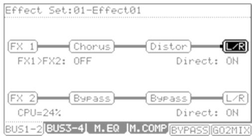
L/R
The effect output will be sent to the Stereo Out.
1/2
The effect output will be sent stereo to [ASSIGNABLE MIX OUT] 1/2.
3/4
The effect output will be sent stereo to [ASSIGNABLE MIX OUT] 3/4.
5/6
The effect output will be sent stereo to [ASSIGNABLE MIX OUT] 5/6.
7/8
The effect output will be sent stereo to [ASSIGNABLE MIX OUT] 7/8.
1-8
The effect output will be sent in MONO to the corresponding [ASSIGNABLE MIX OUT] output.
Using Master Effects
The master effect is applied to the overall sound from the stereo out. You can use it separately from the four effects busses. The effects you can use as the master effect are a 4 band equalizer and compressor. With these effects you can add the final touches to the sound.
- Press [MODE] and [F11] (EFFECTS) to enter EFFECT mode.
-
To use the 4 band EQ, press [F3] (M.EQ) and select ON in the 'EQ' field.
-
To use the compressor, press [F4] (M.COMP) and select ON in the 'Compressor' field.
Note: If you do not want to use master effects, set these fields to OFF.
■ Editing the Master Effects
In addition to the four effects busses, the MPC5000 also has Master Effects, used for polishing up the entire Sequence, affecting all sound from the Main Outs.
In this section, you will learn how to access the master effects.
4 band EQ
This is the 4 band EQ (equalizer), which consists of two shelving type EQs for high frequency and low frequency shaping and a 2 band parametric EQ. With the equalizers, you can boost or lower a specific frequency to control the sound from the stereo out.
To access the MASTER EQ page, do the following:
- Press [F3] (M.EQ).
- Select the 'EQ' field and set it to 'ON'.
- Edit the MASTER EQ Parameters as desired.
The controls for each band are organized into columns. Each of these controls can be edited by turning the [DATA] wheel, or by moving the corresponding Q-LINK controls.
Compressor
This effect compresses the signal level that exceeds the selected level to make the volume even as a whole. The fields are the same as those of the COMPRESSOR, which is selected in the buss effects.
To access the MASTER COMPRESSOR, do the following
- Press [F4] (M.COMP).
- Select the 'Compressor' field and set it to 'ON'
- Edit the MASTER COMPRESSOR parameters as desired.
The MASTER COMPRESSOR is a high quality compressor/limiter designed to be transparent enough to be used to affect the entire mix. Each of these controls can be edited by turning the [DATA] wheel, or by moving the corresponding Q-LINK controls.
| EQ:ON | |||
| Freq 20 | Freq 40 | Freq 40 | Freq 80 |
| 100 | M1D1 | M1D2 | HIGH |
| Q 0 | Q 0 | Q | |
| Gain 0.0dB | Gain 0.0dB | Gain 0.0dB | Gain 0.0dB |
| BUS1-2 BUS3-4 M.EQ | M.COMP BYPASS1G02MIX | ||
| Compressor:ON | |||
| Thresh.. | Attack | Decay | Ratio |
| 28 | 0 ① | 0 ④ | 40 ① |
| Gain ① 0 | |||
| BUS1-2|BUS3-4 M.EQ | M.COMP | BYPASS|G02MIX | |
Editing the Effect Set
The Effect Set is all the parameters of each effects bus, and all the settings of the master effects. Each Effect Set can have completely different settings, and you can switch the effect sets in the 'Effect' field of the SELECT page.
Tip: You can switch the effect sets within a sequence by entering an EFFECT SELECT event to the sequence. For more information, see 'STEP EDIT Mode' on page 43.
In this section, you will learn how to change the name of, copy, and reset the Effect Set.
Changing the name of the Effect Set
- Select the 'Effect Set' field at the top of the BUS1-2 or BUS3-4 page.
- Press the [WINDOW] button.
The EFFECT SET window will be displayed.
- In the 'Name' field, turn the [DATA] wheel.
The Name window will be displayed and you can change the Effect Set name. For more information about the operation in the Name window, see page 18.
- In the Name window, press the [F5] (ENTER).
It confirms the name and closes the Name window.
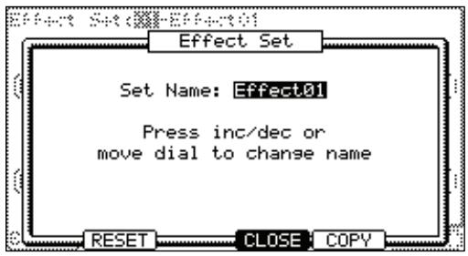
■ Copying the effect set
- Select the 'Effect' field at the top of the BUS1-2 or BUS3-4 page.
- Press the [WINDOW] button.
The Effect Set window will be displayed.
- In the Effect Set window, press the [F5] (COPY) button.
The 'Copy Effect Settings' window will be displayed.
- In the 'From' field, select the source effect set.
- In the 'To' field, select the destination effect set.
- Press the [F5] (DO IT) button.
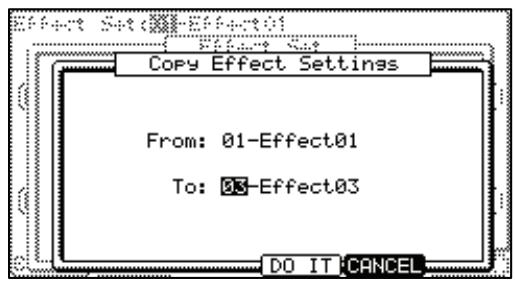
The Effect Set selected in the 'From' field will be copied to the effect set selected in the 'To' field. Pressing the [F4] (CANCEL) button cancels the operation and closes the window.
Resetting the effect set
You can reset the setting for the Effect Set to the default settings.
- Select the 'Effect Set' field at the top of the BUS1-2 or BUS3-4 page.
- Press the [WINDOW] button.
The EFFECT SET window will be displayed.
- In the EFFECT SET window, press the [F2] (RESET) button.
The RESET EFFECT SETTINGS window will be displayed.
- In the 'Effect' field, select the effect set you wish to reset.
- Press [F5] (DO IT).
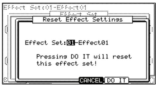
The settings of the effect set selected in the 'Effect' field will be reset to the default settings. Pressing the [F4] (CANCEL) button cancels the operation and closes the window
Chapter 16: Saving and Loading (DISK Mode)
Samples or sequences you create in the MPC5000 will be lost when you turn off the unit. If you wish to keep the data, you need to save it. You can use the saved files again by loading them into the MPC5000.
About memory cards
The MPC5000 uses Type I or Type II compact flash cards. Cards in sizes up to 2 gigabytes are supported. The MPC5000 comes with one compact flash card containing factory sounds to get you started, but you can use any compatible card for saving.
Tip: MB indicates the size of the memory card. The larger this number is, the more data you can store.
Note: The size of the compact flash card that MPC5000 can handle is from 32MB to 2GB.
Note: When you use a new compact flash card with the MPC5000, you need to format the card before using it. For more information about formatting the card, see the ' Formatting' section on page 161.
Saving
In this section, you will learn how to save your work. This is done in the SAVE page, which can be accessed by pressing the [MODE] and [PAD 3] (DISK).
Selecting the destination
You can choose where to save your files on a memory card or the internal Hard Disk. Here, you will learn how the data will be saved, and how to select the destination.
- Press [MODE] and [F3] (DISK)
This will open the DISK page.
- Press [F2] (SAVE)
The SAVE page will be displayed.
- Select the device you would like to save to.
For this example, choose the Hard Drive.
- Move through the directory using the left/right cursor buttons.
The files in the Hard Disk are saved in the directories hierarchically, like other computer files.
You can use the [DATA] wheel to move through the list to select different folders. Pressing the left/right [CURSOR] buttons will move through the directories.
For example, as shown in the picture above, when you scroll with the [DATA] wheel to select the AUTOLOAD folder and then
press the right cursor button again, the AUTOLOAD folder will be displayed above the Directory List, and the contents of the AUTOLOAD folder will be displayed. If you press the left cursor button, the Directory List will go back up to the ROOT directory.
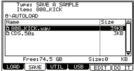
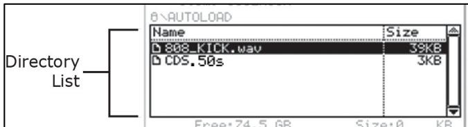
Tip: The ROOT folder indicates the top directory of the Hard Disk. There is no other upper directory.
- Select the folder you wish to save the data to.
If you wish to create a new folder, proceed to the next step. If not, proceed to the next section, which details saving each file type.
Saving to Compact Flash
In order to save to Compact Flash, replace HARD DRIVE with CF CARD in step #3 above.
Note: Make sure that you insert the compact flash card completely into the slot.
Creating a New Folder
You can create a new folder and select it as the destination.
- Press F2 to enter the SAVE tab.
- Select the directory in which you wish to create a new folder.
The new folder will be created in the folder currently selected. The name and path of the current folder will be displayed above the navigation window.
- Press and hold the F5 button.
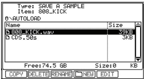
The Function row will change as displayed on the right.
- Press the [F4]NEW) button.
This will open the NAME EDIT window.
- Specify a name for the new folder.
For more information about setting the name, see the 'Setting Names' section on page 18.
- In the NAME EDIT window, press the [F5] (ENTER) button.
The new folder will be created in the selected directory. In the Directory window, the new folder is selected.
Saving a Sample
You can save samples one by one.
- Select the destination folder for the sample to be saved.
See page 149 for more information on selecting destination folders.
-
In the 'Type' field, select SAVE A SAMPLE.
-
In the 'Item' field, select the sample to save.
You can scroll through all samples in memory by turning the [DATA] wheel.
- Press the [F6] (DO IT) button.
The MPC5000 starts saving the sample.
When the destination folder has the data with the same name
If the destination folder already has the data with the same name, the FileExists window will be displayed.
To cancel the operation, press [F4] (CANCEL).
To overwrite the data on the memory card with the new data, press the [F2] (REPLAC) button. The data in the memory card will be replaced with the new data.
Pressing the [F5] (RENAME) button brings up the Name window, where you can change the name of the file you are about to save. When you enter the name in the Name window and press the [F5] (ENTER) button, the MPC5000 will start to save the data.
Saving a Synth or Sample Program
You can save a synth program, or a sample program and all the samples used for that program by doing the following:
- Select the destination folder for the program to be saved.
See page 149 for more information on selecting destination folders.
-
In the 'Type' field, select SAVE A PROGRAM.
-
In the 'Item' field, select the program to save.
You can select any program in memory by turning the [DATA] wheel.
- Press the [F6] (DO IT) button.
If the program is a Synth Program, the program will be saved. If the program to be saved is a Sample Program, the SAVE A PROGRAM window will be displayed.
- In the Save a Program window, choose the settings for each of the following fields.
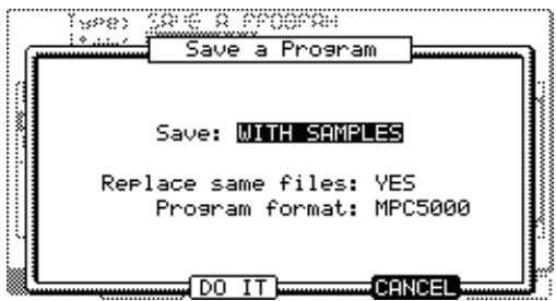
Save
You can choose whether or not to save the sample data (sounds) with the program data.
WITH SAMPLES
The MPC5000 will save the program data and the samples used for the program.
Normally you should select this option. When you load the saved program, the MPC5000 will load the samples automatically.
PROGRAM ONLY
The MPC5000 will save only the program data. It does not save the sample data. When you are sure that the samples used for the program are in the selected folder, you can reduce the time to save the data by selecting this operation.
Replace same files
This determines how to handle files when the destination location already has a sample with the same name.
NO
The MPC5000 will not save the file with the same name. If you loaded the data from the memory card and edited only the program, select NO.
YES
The MPC5000 will overwrite the data with the new data, which you are about to save. If you have loaded the data from the memory card and edited the sample data, select YES.
Program Format
This allows you to choose whether to save the program in native MPC5000 format, or legacy MPC1000 format, for compatibility with the MPC1000, MPC2500, and MPC500.
MPC5000
The Program will be saved in native MPC5000 format as a .50S file. This file will retain MPC5000 specific formatting, such as simultaneous pad settings, random and cycle play modes, and filter settings.
MPC1000
The program will be saved in legacy MPC1000 format as a .PGM file. This file will be able to be opened on an MPC1000, MPC2500 or MPC500, but will lose any MPC5000 specific formatting, such as such as simultaneous pad settings, random and cycle play modes, and filter settings.
Tip: the MPC1000, MPC2500 and MPC500 have a memory maximum of 128MB, so be sure that the program you are saving totals less than 128MB if you wish to open it on a legacy MPC.
- Press the [F5] (DO IT) button.
The MPC5000 will start to save the data.
Note: If the destination folder already has the data with the same name, the FileExists window will be displayed. For more information about the File Existing window, see the 'Saving a Sample' section on page 150.
Saving all Programs and Samples
You can save all the programs and the samples in the MPC5000 at the same time.
- Select the destination folder for the files to be saved.
See page 149 for more information on selecting destination folders. - In the 'Type' field, select SAVE ALL PROGRAMS &SAMPLES.
- Press the [F6] (DO IT) button.
The SAVE ALL PROGRAMS window will be displayed.
- In the Save a Program window, make the settings for each field.
'Make new folder' field
When you save the data you can create a new folder inside in the current folder, and save the data in the new folder. When you use SAVE ALL PROGRAMS &SAMPLES, a lot of data may be saved.
With the Make new folder option, you can easily create a folder for the data you wish to save.
NO
The MPC5000 will save the data in the selected folder. A new folder is not created.
YES
The MPC5000 will create a new folder and save the data in that folder.
If you select NO, the Replace same files field will be displayed. If the destination folder already has the file with the same name, select NO to cancel the operation and select YES to replace the file with the new data. When you select YES, the Folder name field will be displayed. Enter the folder name in this field.
- Press the [F5] (DO IT) button.
The MPC5000 will start saving the data.
Saving a Sequence
You can save sequences individually.
Note: The MPC5000 saves it's sequences in standard MIDI format, using metadata to save it's MPC specific parameters. These files will be readable in other sequencers as standard MIDI Type 1 files, but non-MPC5000's will not recognize MPC Specific information. This includes Track and Pad Mute, Q-Link and Mixer Automation and 16 Levels Tuning.
- Select the destination folder for the sequence to be saved.
See page 149 for more information on selecting destination folders.
- In the 'Type' field, select SAVE A SEQUENCE
- In the 'Item' field, select the sequence that you wish to save.
You can select any sequence in the memory by turning the [DATA] wheel.
- Press the [F6] (DO IT) button.
The SAVE A SEQUENCE window will be displayed. - Press the [F5] (DO IT) button.
The MPC5000 will start saving the data.
Note: If the destination folder already has the data with the same name, the FileExists window will be displayed. For more information about the File Existing window, see the 'Saving a Sample' section on page 150.
Saving All the Sequences and the Songs at the Same Time
You can save all the sequences and the songs in the MPC5000 at the same time.
The MPC5000 will save the data as one file called "ALL file", which include all the sequence and the songs, instead of saving individual sequences and song files.
When you load the ALL file, you can reset all the sequences and the songs to the status when they are saved. The ALL file includes the effect set data.
- Select the destination folder for the files to be saved.
See page 149 for more information on selecting destination folders. - In the 'Type' field, select SAVE ALL SEQS AND SONGS.
- Press the [F6] (DO IT) button.
The SAVE ALL SEQS & SONGS window will be displayed.
- In the 'File name field' select the file name to save.
- Press the [F5] (DO IT) button.
The MPC5000 will start saving the data.
Saving All Data In Memory
You can save sample/program/ALL files at the same time. When you save the data, a project file will be saved, as well as a sample, program and ALL files. The project file does not have actual sample or sequence data, but it has the information about the sample/program/ALL files that are saved when you save the data. When you load the project file, the sample/program/ALL files saved with the project file will be loaded automatically and set the MPC5000 to the same status when you saved the data.
For example, if you select SAVE ENTIRE MEMORY when you save the data after finish working on it for the day, you can start the MPC5000, the next day, from where you finished the previous day.
- Select the destination folder for the files to be saved.
See page 149 for more information on selecting destination folders. - In the 'Type' field, select SAVE ENTIRE MEMORY.
- Press the [F6] (DO IT) button.
The SAVE ENTIRE MEMORY window will be displayed.
- In the 'Project name' field, select the name of the project file to save.
- In the 'Replace same files' field, set how to handle the file when you already have the data with the same name as the loading file in the unit.
NO
The MPC5000 will not save the file with the same name.
YES
The MPC5000 will overwrite the data by with new file.
- Press the [F5] (DO IT) button.
The MPC5000 will start saving the data.
About Input Thru (.IPT) File
If you use "SAVE ENTIRE MEMORY" to save the internal memory data, the Input thru file will be saved with the Project file. The Input Thru file contains the setting of the Input Thru in the MPC5000. When you load the Project file, the Input Thru file will be loaded automatically with the Project file. You can also load only the Input Thru file (IPT File) in the Load page.
■ Renaming a File
You can change the name of the file in the memory card.
- Select the desired file with the [CURSOR].
You can move through directories with the left/right [CURSOR] buttons.
- Press and hold the [F5] (EDIT) button.
The Function buttons will change as shown.
- While holding in the [F5] (EDIT) button, press the [F3] (RENAME) button.
The NAME EDIT window will be displayed.
- Enter the new name and press the [F5] (ENTER) button.
For more information about setting the name, see the 'Setting Names' section on page 18.
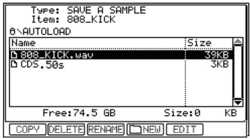
Note: If you change the file name, the MPC5000 may not be able to load the file properly. For example, the samples used for a program are saved in the program file as the sample name. If you change the name of the sample file, the MPC5000 cannot find it when loading the program.
- Deleting a File
To delete the files on the hard drive or memory card, do the following.
-
Press F2 to open the SAVE page.
-
Select the desired file with the cursor.
You can move through the directories with left/right cursor buttons.
- Press and hold the [F5] (EDIT) button.
The Function buttons will change as shown.
- While holding in the [F5] (EDIT) button, press [F2] (DELETE).
The selected file will be deleted.
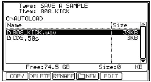
Note: You can select a folder and delete it. If you delete a folder, all the files in that folder will be deleted.
Copying Files
To copy files from one folder to another, or from one drive to another, do the following:
- Press F2 to open the SAVE page.
- Select the desired file or folder to move with the cursor.
You can move through the directories with left/right cursor buttons. - Press and hold the [F5] (EDIT) button.
The Function buttons will change as shown. - While holding in the [F5] (EDIT) button, press [F1] (COPY).
- This will copy the selected file and open the COPY TO... window.
- In the Directory List, select the directory to paste the file to.
- Press [F5] (PASTE).
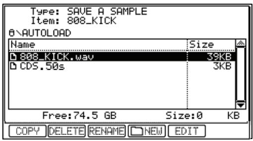
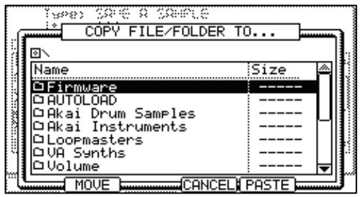
The selected file will be copied to the selected location.
■ Moving Files
When moving a file, the file is copied to a new location, and then deleted from the original location. To move files from one folder to another, or from one drive to another, do the following:
- Press F2 to open the SAVE page.
- Select the desired file or folder to move with the cursor.
You can move through the directories with left/right cursor buttons.
- Press and hold the [F5] (EDIT) button.
The Function buttons will change as shown.
- While holding in the [F5] (EDIT) button, press [F1] (COPY).
This will copy the selected file and open the PASTE TO... window. - In the Directory List, select the directory to move the file to.
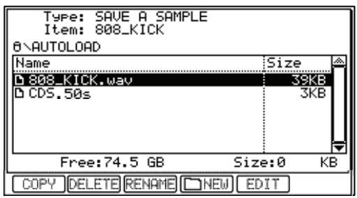
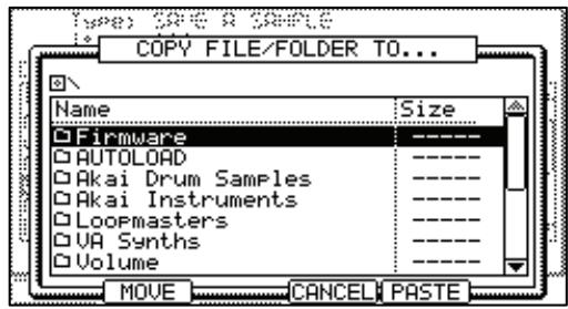
- Press [F2] (MOVE).
The CONFIRM MOVE window will be opened. The selected file will be moved to the selected location. - Press [F5] (DO IT).
The selected file will be moved to the new location.
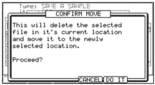
Note: A folder can only be MOVED or COPIED to a different media, such as hard disk to compact flash, or CD to hard disk, for example.
Loading
In this section, you will learn how to load a file. The MPC5000 can load files from Memory Card, Internal Flash Memory, the Internal Hard Disk, or the Internal CD Drive (optional). This is done in the LOAD page, which is accessed by pressing the [MODE] button and then the [PAD 3] (DISK).
Selecting a File
To select a file to load, proceed as follows:
- Press the [MODE] button and the [PAD 3] (DISK).
The LOAD page will be displayed. If another page is displayed, press [F1] (LOAD).
- Select the location you wish to load data from.
ROM Flash
The MPC5000 will load the data from the internal preset memory. Normally, when you switch on the MPC5000, it will load the data from the preset memory, but you can load these files individually by selecting 'ROM Flash' here.
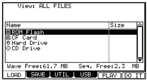
MEMORY CARD
The MPC5000 will load the files from the memory card in the card slot.
HARD DISK
The MPC5000 will load the files from the internal HARD DISK.
CD (Optional)
The MPC5000 will load the files from CD-ROM disk in the internal CD Drive. (Optional).
- In the Directory List, select a file to be loaded.
Files can be selected by turning the [DATA] wheel. Use the left and right [CURSOR] buttons to navigate through the directory. For more on navigating through directories, see 'Selecting the destination' on page 149. - Select the file you wish to load.
- Press the [F6] (DO IT) button.
The MPC5000 will load the selected file.
The next procedures differ depending on the type of selected file.
Tip: When the sample is selected in File: field in LOAD page, you can audition the sample by pressing F5 button
About the 'View' field...
The View field of the LOAD page is normally set to ALL FILES to display all types of the files in the 'Directory' field. You can change the setting of the View to display only the selected type of files. It is useful when you need to find a file from a large list. Select the 'View' field and select the file type to display by turning the [DATA] wheel.
Loading a Sample
You can load a sample file one by one. You can also assign that sample to the pad.
- Select a sample file and load it. The LOAD A SAMPLE window will be displayed.
You can listen to the sample by pressing the [F2] (PLAY) button.
To cancel the loaded sample, press the [F4] (DSCARD) button.
- Select the pad to assign the selected sample to by hitting it.
When you hit the pad, the pad number will be displayed in the Assign to pad field.
If you do not wish to assign the sample to any pad, select OFF by turning the [DATA] wheel to the left.
- Press the [F5] (KEEP) button.
The loaded sample will be assigned to the selected pad.
Tip: You can load ".snd" files. This includes files from MPC3000/2000/2000XL.
Loading Audio from the Internal CD Drive (optional)
If you select "CD" in the 'Source' field, you can load audio tracks from the Audio CD in the internal CD drive (optional) as well as the sample file.
- In the File field, select the track.
You can audition the selected track with pressing [F4] (PLAY) button. - Press the [F5] (DO IT)
The MPC5000 will start loading the audio track.
Note: The MPC5000 cannot load an audio track that is greater in size than is available in the internal memory. The data size of the selected track will be displayed in 'Size' column next to the file's name.
The maximum internal memory with the EXM-E3 (optional) module installed is 192MB.
Approximately 18 minutes can be sampled in this manner as you will need approximately 10MB for each stereo track minute.
Loading a Program
You can load a program file one by one.
- Select a program file and load it. The LOAD A PROGRAM window will be displayed.
To cancel the operation, press the [F4] (CANCEL) button.
- In the 'Load' field, select if you wish to load the samples as well.
WITH SAMPLES
The MPC5000 will load the samples used for the program as well. Normally select this option.
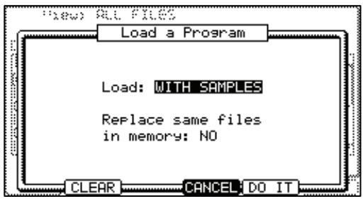
PROGRAM ONLY
The MPC5000 will load only the program file. It does not load the samples. Select this option when you wish to create a new program by assigning different samples to the saved program.
- If you selected WITH SAMPLES in the 'Load' field, make settings in the 'Replace same samples in memory' field.
You can set how to handle the file when you already have the data with the same name as the file that is to be loaded.
NO
The MPC5000 will not load the sample with the same name.
YES
The MPC5000 will overwrite the data with the new data.
- Press the [F5] (DO IT) button.
The MPC5000 will start loading the data.
- Deleting All Data in Memory Before Loading
When you press the [F2] (CLEAR) button instead of the [F5] (DO IT) button in step 4 you can clear the MPC5000's memory and load only the selected program in the memory.
- In the step 4, press the [F2] (CLEAR) button instead of the [F5] (DO IT) button.
The CAUTION window will be displayed. If you press the [F5] (DO IT) button, the MPC5000 will start loading the program after it clears all its internal memory.
Note: If you do this operation, all the data in memory will be deleted.
Loading a Sequence
You can load sequence files individually.
- Select the sequence file and load it. The LOAD A SEQUENCE window will be displayed.
- In the 'Load into' field, select the destination sequence number.
Select the sequence number to load the data to.
- Press the [F5] (DO IT) button.
The MPC5000 will start loading the data.
Loading the ALL File
You can load the ALL file, which has sequence and song data. When you load the ALL file, all the sequences and songs which are currently in the MPC5000 will be replaced by the new data.
- Select the ALL file and load it. The Load ALL (SEQS&SONGS) File window will be displayed.
- Press the [F5] (DO IT) button.
The MPC5000 will start loading the data.
Loading Individual Sequences from the ALL File
- Select the ALL file and load it. The Load ALL (SEQS&SONGS) File window will be displayed.
- Press the [F3] (SEQ) button.
The Load a Sequence window will be displayed.
- In the Load file field, select the sequence to load.
In the Load file field, you can select sequence data from the ALL file. - In the Load into field, select the destination sequence.
Select the sequence number to load the data to. - Press the [F5] (DO IT) button.
The MPC5000 will start loading the data.
Loading Only the Effect Set from the ALL File
The ALL file has effect set file, which has the effect setting information. You can load only the effect set from the ALL file.
- Select the ALL file and load it. Load ALL (SEQS&SONGS) File window will be displayed.
- Press the [F2] (EFFECT) button.
The Load Effect File window will be displayed.
- In the Load file field, select the effect set to load.
- In the Load into field, select the destination effect set.
Select the effect set number to load the data to. If you select ALL in the Load file field, the current effect set in the unit will be replaced by the data from the ALL file.
- Press the [F5] (DO IT) button.
The MPC5000 will start loading the data.
Loading a Folder
You can load a folder and load all the files within the folder at the same time. You can load program, sample, and ALL files.
- Select a folder and load it. The Load Folder window will be displayed.
- Make a setting in the Replace same files in memory field.
You can set how to handle the file when you already have the data with the same name as the loading file in the unit.
NO
The MPC5000 will not load the file with the same name.
YES
The MPC5000 will overwrite the data in the unit with the loaded file.
- Press the [F5] (DO IT) button.
The loading will begin.
Loading a Folder after Deleting All Data in Memory
When you press the [F2] (CLEAR) button instead of the [F5] (DO IT) button in step 3, you can clear the MPC5000's memory and load the selected folder.
- In the step 3, press the [F2] (CLEAR) button instead of the [F5] (DO IT) button.
The CAUTION window will be displayed. If you press the [F5] (DO IT) button, the MPC5000 will start loading the folder after it clears all its internal memory.
Note: If you do this operation, all the data in memory will be deleted.
Note: If the folder has several ALL file, the MPC5000 will load only one of them.
Loading a Project
When you use SAVE ENTIRE MEMORY mode to save the data, the MPC5000 will load the project file that was created. When you load a project file, all the data currently saved in the unit will be overwritten by the data that the project file will load.
- Select a project file and load it.
The CAUTION window will be displayed.
- Press the [F5] (DO IT) button.
The loading will begin.
Loading an Input Thru File
If you use 'SAVE ENTIRE MEMORY' to save the internal memory data the Input thru file will be saved with the Project file. The Input Thru file contains the settings of Input Thru in the MPC5000.
When you load the Project file, the Input Thru file will be loaded automatically with the Project file. You can also load only the Input Thru (.IPT file) file in the Load page.
Burning CDs
Audio CDs
Adding the optional DVD/CDR-W drive (CD-M25) to the MPC5000 will allow burning of Audio and Data CDs as well as reading audio and data CDs and DVDs. To create an audio CD, do the following.
- Press [F3] (UTILIT).
The UTILITY page will be displayed
- Select WRITE AUDIO CD in the 'Function' field.
When a disk is inserted into the CD drive, you will see EMPTY DISC in the 'Disk Status' field, as well as (R) or (RW) indicating whether the disk is a recordable (R) or rewrites (RW) type CD.
- Select the location of the audio file you wish to write to the CD.
You can select RAM, Hard Disk, or Memory card as the source in the Directory List, as well as which folder it resides in.
- Press [F6] (DO IT) to write the file to the disk.
The WRITE CD-R/RW window will be displayed.
- Press F5
The MPC5000 will begin writing the audio file to the CD. Each audio file will be its own individual track.
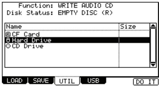
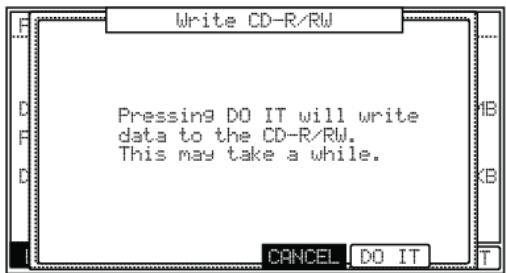
You may repeat the above process until the disk is full, or you've added
all the tracks you wish to have on your CD. Once you are satisfied with the content of your CD, the CD will need to be closed. This will finish the CD, and allow it to be played on any compact disk player. See the section titled 'Close Session' on page 160 for more information.
Data CDs
This function will allow you to create Data CDs, which can hold any type of file. This is perfect for backing up your work, or making a copy of your work to share with other MPC5000 users.
To create a Data CD, do the following.
- Press [F3] (UTILIT).
The UTILITY page will be displayed
- Select WRITE DATA CD in the 'Function' field.
When a disk is inserted into the CD drive, you will see EMPTY DISC in the 'Disk Status' field, as well as (R) or (RW) indicating whether the disk is a recordable(R) or rewrites (RW) type CD.
- Select the location of the file or folder you wish to write to the CD.
You can select RAM, Hard Disk, or Memory card as the source in the Directory List, as well as which folder it resides in. You also can preview audio files selected by pressing [F5] (PLAY).
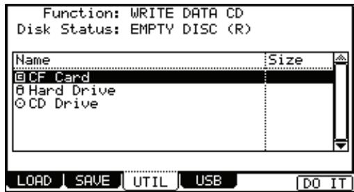
Tip: You can choose any type of file, a folder, or even an entire drive, provided the CD-R has enough free space to hold the selected data.
- Press [F6] (DO IT) to write the selected data to the disk.
The WRITE CD-R/RW window will be displayed.
- Press F5
The MPC5000 will begin writing the data to the CD. The data will be automatically written to the ROOT of the CD. If you write a folder to the CD, additional files and folders within the selected folder will be copied within that folder, maintaining the directory structure.
You may repeat the above process until the disk is full, or you've added all the files you wish to have on your CD. Once you are satisfied with the content of your CD, the CD will need to be closed. This will finish the CD,

and allow it to be accessed on a computer, or another CD equipped MPC. See the section titled 'Close Session' on page 160 for more information.
Erasing CD-R/Ws
The major advantage CD-RWs have over standard CD-R's is the ability to erase and rewrite data to the disk before it is closed. Once a CD-RW is closed, a CD-RW, like a regular CD-R will be able to be played in any compact disk player, but unlike a CD-R, a CD-RW can be erased and used again.
To access the ERASE CD-RW function, do the following:
- Press [F3] (UTILIT).
The UTILITY page will be displayed
-
Select ERASE CD-RW in the 'Function' field.
-
Press [F6] (DO IT) to erase the CD-RW
The ERASE CD-RW page will be displayed.
- Press [F5] (DO IT) to erase the CD-RW.
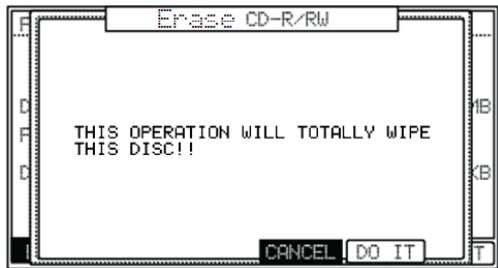
Close Session
Once you are satisfied with the content of your CD, the CD will need to be closed. This will finish the CD, and allow it to be played on any compact disk player.
To access the CLOSE SESSION function, do the following:
- Press [F3] (UTILIT).
The UTILITY page will be displayed
-
Select CLOSE SESSION in the 'Function' field.
-
Press [F6] DO IT
The CLOSE SESSION page will be displayed.
- Press [F5] (DO IT) to close the CD session.
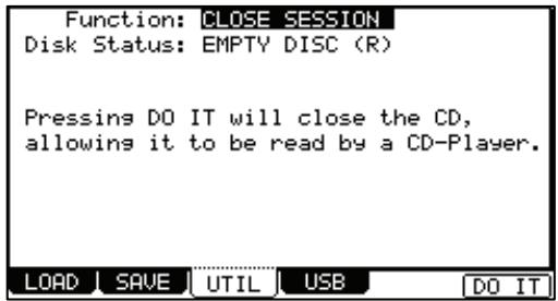
Autoload
The MPC5000 comes with an array of factory demos, as well as preset Sample and Synth Programs that load on startup from a preset ROM. Instead, it can be set to automatically load a particular folder on startup instead. When you create an AUTOLOAD folder on a memory card or Hard Disk, the MPC5000 can be set to load the contents of the AUTOLOAD folder automatically when you switch on the unit. You can use this function to load the most frequently used programs or sequences automatically.
Creating an Autolog
The MPC5000 can be set to automatically load a particular folder on startup instead of the preset ROM. When you create an AUTOLOAD folder on the memory card or Hard Disk, the MPC5000 can be set to load the contents of the AUTOLOAD folder automatically when you switch on the unit. You can use this function to load the most frequently used programs or sequences automatically.
- Create a folder named AUTOLOAD on the desired device.
For this example, create a folder named AUTOLOAD on the Hard Disk.
- Save any files you would like loaded on startup.
This can include any of your favorite samples, sample programs, synth programs, and sequences.
-
Press [F3] (UTIL).
-
The UTILITY page will be opened.
-
In the 'Function' field, select SAVE AUTOLOAD
-
In the 'Autoload' field, select the device you wish to load from.
For our example, choose Hard Disk
- Press [F6] (DO IT).
Now, when the MPC5000 starts up, it will look to the ROOT of the selected device, and search for a folder named AUTOLOAD. When found, it will automatically load the folder you created in step 1.
Function: AUTOLoad
The MPC5000 will look to the selected device and automatically load the contents of the folder named AUTOLOAD on startup.
Autoload: HARD DISK
LOAD SAVE
UTIL
USB
D0
Restoring the Factory Autolog
To restore the factory Autolog, do the following:
- Press [F3] (UTIL).
- The UTILITY page will be opened.
- In the 'Function' field, select SAVE AUTOLOAD
- In the 'Autoload' field, select 'INTERNAL MEMORY'.
- Press [F6] (DO IT).
The next time the MP5000 is started, the preset ROM will be loaded automatically.
Turning Autolog Off
If you would prefer the MPC to start without loading anything at all, do the following:
- Press [F3] (UTIL).
- The UTILITY page will be opened.
- In the 'Function' field, select SAVE AUTOLOAD
- In the 'Autoload' field, select 'OFF'.
- Press [F6] (DO IT).
The next time the MPC starts, nothing will be preloaded.
Formatting
You can format either the hard drive or the memory card. Please note that if you format a drive, all the data in the card will be deleted.
- Press the [MODE] and [PAD 3] (DISK).
- Press the [F3] (UTILIT) button.
The UTILITY page will be displayed.
- In the 'Function' field, select FORMAT.
- Select the desired device to format.
- Press the [F6] (DO IT) button.
The CAUTION window will be displayed.
- Press the [F5] (DO IT) button.
The MPC5000 will start formatting the card.
Chapter 17: Q-LINK Controllers
By using the Q-LINK sliders and knobs, you can control certain pad parameters (filter, tune, etc...) with a slider or knob. There are two ways (NOTE ON and REALTIME) for controlling the sound by Q-LINK.
NOTE ON
The sound will be affected to the position of Q-LINK slider/knobs at the point the Pad is hit. But the sound will not be affected by changing the Q-LINK slider/ knobs after hitting the pad.
REALTIME
You can change the sound during playing back by changing the Q-LINK slider/knob.
Alternatively, Q-LINK controllers can be set to send MIDI controllers to external devices.
In this section, you will learn how to set the Q-LINK sliders or knobs. This is done in Q-LINK mode, which can be accessed by pressing the [MODE] button and then the [PAD 1] (Q-LINK) button.
Configuring the Q-LINK Sliders & Knobs
- Press [MODE] + [PAD 1] to enter Q-LINK mode, and press [F1] (Q-LINK) to open the Q-LINK page.
The Screen shown to the right will be displayed. Each of the following settings for each Q-LINK is quickly displayed here.
MIDI CONTINUOUS CONTROLLER (#)
Displays which MIDI Continuous Controller will be sent out when the selected controller is moved
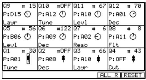
Pad (P)
Displays which pad the Q-LINK Controller is set to.
Parameter
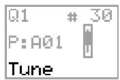
Displays which parameter is to be edited with the selected Q-LINK
- Select one of the Q-LINK controls.
When you move a Q-LINK controller, that controller will be highlighted. You can also select a Q-LINK Control with the [CURSOR].
- Press the [WINDOW] button.
This will open the Q-LINK EDIT window as shown on the right.
- Select the 'Assign' field and select the pad you wish to assign the selected Q-LINK to.
You can select the pad you wish to edit by hitting the desired pad, or scrolling with the [DATA] wheel. The effect of the slider or knob will be applied to the selected pad. If you do not wish to use the Q-LINK function for any pad, select OFF by turning the [DATA] wheel.
- In the 'Change' field, select the condition for changing the parameter.
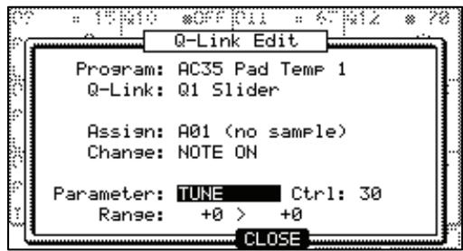
NOTE ON
The setting value of the Q-LINK slider/knob at hitting the pad affects to the sound. If you change the Q-LINK slider/knob while the sound is playing back, the sound will not be changed. The information of the slider or knob position will be sent to the sampler section as Note Variation data The Note Variation data is included in the Pad Event and converts the specific parameter value to slider or knob position data. For example, when you select TUNE as a parameter, by moving the slider, you can affect the sample tune.
REAL TIME
If you change the Q-LINK slider/knob while the sound is playing back, the sound will be changed. When REAL TIME is selected, the information of Q-LINK slider/knob is recorded as a Q-LINK event, not as Note Variation data.
- In the 'Parameter' field, select the parameter you wish to control.
When the REAL TIME is selected in the 'Change' field
TUNE
This controls the sample's pitch. (Sample Programs only)
LEVEL
This controls the sample's volume level.
CUTOFF
This controls the cutoff frequency of the Filter.
RESONANCE
This controls the resonance value of the Filter
PAN
This control the sample's pan position.
ATTACK
This controls the attack time of the Amp Envelope.
DECAY
This controls the decay time of the Amp Envelope.
RELEASE
This controls the release time of the Amp Envelope
When the NOTE ON is selected in the 'Change' field
TUNE
This controls the sample's pitch. (Sample Programs only)
LAYER
This allows you to alter the HIGH and LOW Range at which the Event will be triggered. (Sample Programs only)
CUTOFF
This controls the cutoff frequency of the Filter.
RESONANCE
This controls the resonance value of the Filter
PAN
This control the sample's pan position.
ATTACK
This controls the attack time of the Amp Envelope.
DECAY
This controls the decay time of the Amp Envelope.
RELEASE
This controls the release time of the Amp Envelope
- In the 'Range' field, set the upper and lower limit of the slider or knobs.
The value of the controlled parameter is determined by the value set here. The value depends on the type of the parameter selected in the Parameter' field.
TUNE:
-120 - +120 - This controls the sample pitch with '10' equaling a semitone.
LEVEL: 0 - 100
This controls the sample volume level.
CUTOFF: -100 - +100
This offsets the cut off frequency of the filter. The value set in the PROGRAM mode is used as 0.
RESO: -100 - +100
This offsets the resonance of the filter. The value set in the PROGRAM mode is used as 0.
LAYER: 0 - 127
This value switches layers instead of Velocity.
ATTACK: 0 - 100
The attack time of the envelope will be replaced with this value.
DECAY: 0 - 100
The decay time of the envelope will be replaced with this value.
Note: When you change the LEVEL or the PAN in REAL TIME by Q-LINK slider/knob, some noise may occur depending on the sound.
- Press [F4] (CLOSE) to return to the Q-LINK page.
Resetting the Q-LINK slider / knob value
You can reset (back to the original value) the altered value of Q-LINK slider/knob.
Example: When you control the Tune of the Pad Event with REAL TIME, the Tune will keep the changed value after you change the Q-LINK slider. If you press the [F5] (ALL R) button or the [F6] (RESET) button, the changed value resets to its original value.
[F5] (ALL R):
All parameters changed with REAL TIME reset to the original value.
[F6] (RESET):
![AKAI MPC5000 - [F6] (RESET): - 1](/content/2025/01/152537/images/e78a083ef0830fe9efeeca0ecda95f6b808f7695d3a6cbbc5932ae8f44b2a816.jpg)
Only the parameter being displayed in Slider page resets to the original value.
Recording the slider/knob value in a sequence
When you use the Q-LINK slider/knob while recording a sequence, the Note Variation data will be recorded into the track of the sequence.
When the NOTE ON is selected in the 'Change' field, the value of the Q-LINK slider/knob will be recorded as Note Variation information with the Pad Event. When the REAL TIME is selected in the 'Change' field, the value of the Q-LINK slider/knob will be recorded as Q-LINK event, independent of the Pad Event.
[FTER] Button
This button sets the operation of the Q-LINK slider/knob. When a sequence is recorded, the Note Variation data is played back. The operation of the [AFTER] button is different with 'NOTE ON' or 'REAL TIME'.
When 'NOTE ON' is selected, if the [AFTER] button is OFF (the LED is off), and you move the Q-LINK slider or knob while playing back a sequence with Note Variation, the Pad's Note Variation is played as recorded. If you hit a Pad during playback, the Pad that you hit will have the effect of Q-LINK slider or knob.
If the [AFTER] button is ON (the LED is lit), and you move the Q-LINK slider or knob while playing back a sequence with Note Variation, the Note Variation value will be replaced with the current position of the Q-LINK slider or knob.
When 'REAL TIME' is selected, if the [AFTER] button is OFF (the LED is off), and you move the Q-LINK slider or knob while playing back a sequence with Note Variation, the recorded Pad's sound will be changed.
If the [AFTER] button is ON (the LED is lit), the recorded Q-LINK Event will be ignored and the current Q-LINK slider/knob position will be used while playing back a sequence with Note Variation.
While recording a sequence,
If the [AFTER] button is OFF, when you move the Q-LINK slider/knob, the new Q-LINK Event will be recorded and added to the existing Q-LINK Events.
If the [AFTER] button is ON, when you move the Q-LINK slider/knob. The new Q-LINK event will be recorded and will erase any previous Q-LINK Events.
Sending MIDI Continuous Controllers with a Q-LINK
The twelve Q-LINK Controllers can also be used to send MIDI to external devices. To configure a Q-LINK to send MIDI Continuous Controller messages, do the following:
- In Q-LINK mode, select the desired Q-LINK Controller.
This can be done by moving the selected controller, or navigating to the desired QLINK Controller with the [CURSOR] buttons.
- Set the 'Assign' and 'Parameter' fields to OFF.
This will allow the Q-LINK to act just as a MIDI control. When both the 'Assign' and 'Parameter' fields are set to OFF, MIDI Continuous Controller Numbers from the selected controller will be recorded to the current sequence.
- Set the 'Ctrl' field to the desired MIDI CONTINUOUS CONTROLLER NUMBER
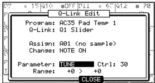
When the Q-LINK is turned, the selected MIDI CONTINUOUS CONTROLLER NUMBER will be sent from the MIDI channel and port of the current track. When recording, moving this Q-LINK will write MIDI Continuous Controller Numbers to the sequence.
Chapter 18: Using the MPC5000 with External Devices
In this section, you will learn how to sync the MPC5000 to the other MIDI devices using MIDI clock and MIDI Time Code. You will also learn how to hook up a MIDI keyboard to your MPC.
MIDI Clock
MIDI clock is a function of the MIDI standard and allows several MIDI devices to synchronize. If your MIDI device supports MIDI clock, you can use the device and the MPC5000 in sync. If you are not sure if your MIDI device supports MIDI clock or not, refer to the device's operation manual.
■ MIDI Sync with the MPC5000 as the master
When you play the MPC5000's sequence, the connected MIDI device will follow. MIDI clock data will be sent from the MPC5000 to the connected MIDI device. In this case, the MPC5000 is called the 'master' and the connected MIDI device the 'slave'.
- Connect the MIDI OUT of the MPC5000 to MIDI IN of the external MIDI device using a MIDI cable.
The MPC5000 has four MIDI Outs: MIDI OUT A, MIDI OUT B, MIDI OUT C, and MIDI OUT D. You can connect to any MIDI output, but for this example connect to the MIDI OUT B. - Select the MIDI/SYNC mode by pressing the [MODE] button and hitting the [PAD 8] (MIDI/SYNC).
- Press the [F2] (SYNC) button.
The SYNC page will be displayed.
- Select the 'Sync out' field and then select the output of the MIDI clock.
You can send out MIDl clock from any of MIDI OUT A or B or C or D. When you select 'AB', MIDl clock is sent from both MIDl OUT A and B. In this example, since you have connected the external MIDl device to MIDl OUT B in step 1, select MIDl OUT B.
- In the 'Mode' field choose MIDI Clock.
- Press the [MAIN] button.
The MAIN page, where you play back the sequence, will be displayed.
- Set the external MIDI device to receive the MIDI clock.
- With help on setting up your external device, please refer to the device's operation manual.
- Press the [PLAY START] button.
The MPC5000 starts playback and the external MIDI device should start playback at the same time.
■ MIDI Sync with the MPC5000 as the slave
The external MIDI sequencer triggers the MPC5000. When the external MIDI sequencer starts playback, the MPC5000 starts playback as well. The MIDI clock is sent from the external MIDI sequencer to the MPC5000. In this case, the external MIDI sequencer works as the master, and the MPC5000 as the slave.
- Connect the MIDI IN of the MPC5000 to MIDI OUT of the external MIDI device using the MIDI cable.
The MPC5000 has two MIDI In ports: MIDI IN 1 and MIDI IN 2. You can connect to either MIDI IN, but here, connect to the MIDI IN 2. - Select the MIDI/SYNC mode by pressing the [MODE] button and hitting the [PAD 8] (MIDI/SYNC).
- Press the [F2] (SYNC) button.
The SYNC page will be displayed.
-
In the 'Mode' field choose MIDI Clock.
-
Press the [MAIN] button.
-
Select the 'Sync in' field and select the input of the MIDI clock.
You can receive the MIDI clock from both MIDI IN 1 and 2. In this example, as you have connected the external MIDI device to MIDI IN 2 in step 1, select MIDI OUT 2.
The main page, where you play back the sequence, will be displayed.
- Set the external MIDI device to send out the MIDI clock.
Refer to the device's operation manual.
- Start the playback of the external MIDI sequencer.
The MPC5000 starts the playback as well.
(EXT) will be displayed in the 'BPM' field.
Note: The tempo being set in the sequence will be displayed when the sequence is stopped.
Note: The MIDI clock signal has tempo information. The slave device will follow the master device's tempo regardless of its original tempo.
Note: The MIDI clock signal does not have time information. If the time settings of the master and the slave are different, they will still play in sync but their time position display may be different.
MIDI Time Code (MTC)
In addition to MIDI clock, the MPC5000 can sync to and transmit MIDI Time Code, or MTC. MIDI Time code is a standard protocol to allow various devices, such as Hard Disk recorders, video cameras and tape based recorders to sync together. MIDI Time Code contains location information in Hours:Minutes:Seconds:Frames, but unlike MIDI Clock, it does not contain tempo information. The following frame rates are supported:
| 24 Frames | Typically used in video productions where the finished product will be transferred to film. Also used in HD video production. |
| 25 Frames | Used in PAL format video production. |
| 30 Drop (29.97)Frames | Used in NTSC video production. |
| 30 Non Drop Frames | Originally used with music video production, this is the most common format forSyncing audio devices. |
NOTE: since MIDI Time Code is used to sync vastly different devices, 'chase' time is often required to ensure that all devices will be accurately locked to the same time. For the MPC5000 it is recommended that a song to be synced to MTC contain at least 1 blank measure in the beginning to allow for accurate sync. Most Hard Disk recorders recommend 10 seconds of chase time. Some tape based video decks require a minimum of 30 seconds. For recommended chase times, please see your master device's owners manual.
Time code Display
Hours:Minutes:Seconds:Frames can be displayed on the MPC5000. From the Main screen, use the [CURSOR] buttons to select the 'Now' field. Scroll with the [DATA] wheel. The display will change as shown.
Now: 08h08m08s08f
MPC5000 as the Slave
To sync the MPC5000 to MIDI Time Code, do the following:
- Connect the MIDI output of your master device to one of the MIDI inputs on the MPC5000.
- Make sure your master device is set to send MIDI Time Code.
- press [MODE] + [PAD 8] (MIDI)
- In the 'Sync in' field, choose the MIDI input the master device is connected to.
- In the 'Mode' field, choose 'MIDI TIME CODE'
When the MPC receives MIDI Time Code, it will automatically determine frame rate, and sync to the master device.
MPC5000 as the Master
To sync MTC capable devices to the MPC5000, do the following:
- Connect the MIDI input of your master device to one of the MIDI outputs on the MPC5000.
- Make sure your slave device is set to receive MIDI Time Code.
- press [MODE] + [PAD 8] (MIDI)
- In the 'Sync out' field, choose the MIDI output the slave device is connected to.
- In the 'Mode' field, choose 'MIDI TIME CODE'
- In the 'Frame Rate' field, select the frame rate appropriate for your slave device.
For more information on appropriate frame rates for your slave devices, consult the devices owner's manual.
■ MIDI Machine Control (MMC)
The MPC5000 is capable of sending and receiving MIDI Machine Control, or MMC. MIDI Machine control is a standard protocol for transport controls. The MPC5000 sends and receives the following:
Send
| MPC Control | MMC Command sent |
| Play | MMC Deferred Play |
| Play Start | MMC Locate Zero, followed by Deferred Play |
| Stop | MMC Stop |
| <> Step, <<Bar>> | MMC Locate |
Receive
| MMC Command sent | MPC equivalent |
| MMC Deferred Play | Play |
| MMC Locate Zero, Deferred Play | Play Start |
| MMC Stop | Stop |
| MMC Locate | Locate |
| MMC Record Strobe | Record |
| MMC Pause | Stop |
Sending MMC to a device
To send MIDI Machine Control to a device, such as a Computer DAW, do the following:
- Connect MIDI out A of the MPC5000 to the MIDI in of the selected device.
- Press [MODE] + [PAD8] (MIDI/SYNC)
The MIDI/SYNC page will be displayed.
- Press [F2] (SYNC) to select the Sync tab.
- Set the 'Sync out' parameter to 'A (Master)'
- Set the 'Send MMC' parameter to 'ON'
- Configure the device to be controlled to receive MMC as per the instructions in the device's manual.
- Press [PLAY] on the MPC5000. The slaved device will start playing along with the MPC5000.
Receiving MMC from a device
To receive MMC from a device, connect the MIDI out of the selected device to the MIDI in of the MPC5000.
To receive MIDI Machine Control from a device, such as a Computer DAW, do the following:
- Connect MIDI in 1 of the MPC5000 to the MIDI out of the selected device.
- Press [MODE] + [PAD8] (MIDI/SYNC)
The MIDI/SYNC page will be displayed.
- Press [F2] (SYNC) to select the Sync tab.
- Set the 'Sync in' parameter to '1 (Slave)'.
- Set the 'Receive MMC' parameter to 'ON'
- Configure the master device to send MMC as per the instructions in the device's manual.
- Press Play on the master device. The MPC5000 will start along with the Master device.
Note: MIDI Machine Control contains only transport controls (start, stop etc). For best results, use MIDI Machine Control in conjunction with another sync method, such as MIDI Time Code, or MIDI Clock.
Connecting the MPC5000 to a MIDI Keyboard with Built-in Sounds
In this section, you will learn how to connect the MPC5000 to a MIDI keyboard which has internal sounds to use the MPC5000's sequencer feature.
Normally, The MIDI keyboard with internal sounds is set to generate sounds when you play the keyboard. However, the MPC5000 sends out any incoming MIDI signals to the MIDI keyboard at the MIDI output. So, if you play the keyboard, the performance will be played in duplicate. To use the MPC5000 as a sequencer, you need to change the setting on the MIDI keyboard so that the MPC5000, not the MIDI keyboard, plays the keyboard's internal sound module.
Normally this could be done by changing the setting called 'local control'. By setting the MIDI keyboard's local control to OFF, you can use the external keyboard and its internal sound module separately.
In this case, the MIDI signal flows as in the figure in the right. The performance data from the MIDI keyboard will be entered to the MPC5000. It will not be sent to the internal sound module.
The MIDI output of the MPC5000 will be sent back to the MIDI keyboard, which will plays the keyboard's sound module. For more information about the setting of your MIDI keyboard's local control, see the keyboard's operation manual. If your MIDI keyboard does not have a local control setting, deactivate the MPC5000's soft through function. In this case, the MPC5000 will output only the data that is recorded on the track, not the incoming MIDI signal.
- Select the MIDI/SYNC mode by pressing the [MODE] button and hitting the [PAD 8] (MIDI).
- Press the [F1] (MIDI) button.
The MIDI page will be displayed.
- Select the 'Soft thru' field and select OFF.
The 'soft thru' field determines how to output the incoming MIDI signal. You can select the following options:
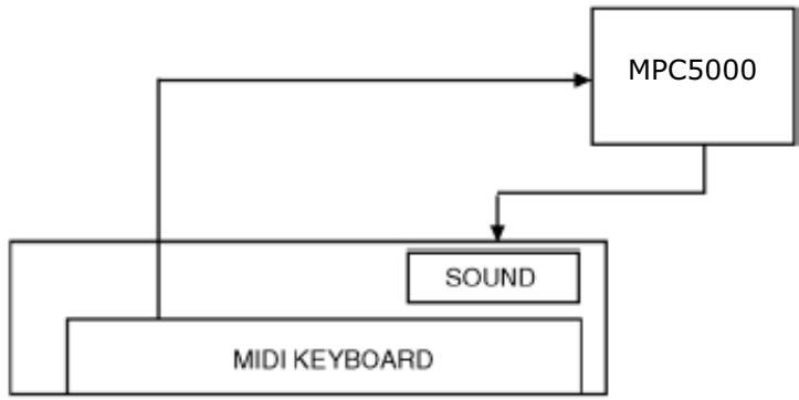
OFF
The MPC5000 will not output the incoming MID1 signal.
AS TRACK
The MPC5000 refers to the MIDI channel setting of the sequence's track. The channel information of the incoming MIDI signal will be replaced with the MIDI channel selected the track.
OMNI-A
The MPC5000 will output the incoming MIDI data as it is from MIDI OUT A.
OMNI-B
The MPC5000 will output the incoming MIDI data as it is from MIDI OUT B.
OMNI-C
The MPC5000 will output the incoming MIDI data as it is from MIDI OUT C.
OMNI-D
The MPC5000 will output the incoming MIDI data as it is from MIDI OUT D.
OMNI-AB
The MPC5000 will output the incoming MIDI data as it is from both MIDI OUT A and B.
OMNI-CD
The MPC5000 will output the incoming MIDI data as it is from both MIDI OUT C and D.
OMNI-ALL
The MPC5000 will output the incoming MIDI data as it is from all of MIDI OUT A, B, C, and D.
MULTI
The MPC5000 will receive MIDI from all channels, and play back MIDI on channels set to the received track.
Setting the MIDI Input Channel
Normally, the MPC5000 can receive the incoming MIDI data regardless of the MIDI channel, so you do not have to worry about the MIDI channel of the connected MIDI devices. You can change the setting to receive only the data on a specific MIDI channel.
- Select the MIDI/SYNC mode by pressing the [MODE] button and hitting the [PAD 8] (MIDI / SYNC).
- Press the [F1] (MIDI) button.
The MIDI page will be displayed.
- Select the 'Active track receive channel' field and select the MIDI channel from which you wish to receive the data.
If you set this field to ALL, the MPC5000 will receive all channels. If you select any channel from 1 to 16, the MPC5000 will receive only the selected channel.
Connecting the MPC5000 as a Multitimbral Sound Module.
In this section, you will learn how to connect the MPC5000 to a MIDI sequencer as a multitimbral sound module, so each incoming MIDI channel will play a different sound. Up to 32 different sounds can be played in this manner.
The MPC can be played with a MIDI sequencer, or a keyboard sending multiple MIDI channels. This allows the MPC's internal Sample and Synth programs to be played by an external source, with each MIDI channel playing a different sound. To use the MPC5000 as a multitimbral sound source, you need to set the MPC to receive midi Multitimbrally.
The MIDI output of the MIDI Sequencer will be sent to one of the MPC5000's MIDI IN's. For information on setting up your sequencer, see the sequencer's operation manual.
- Select the MIDI/SYNC mode by pressing the [MODE] button and hitting the [PAD 8] (MIDI).
- Press the [F1] (MIDI) button.
The MIDI page will be displayed.
- Select the 'Active Track Receive Channel' field and select MULTI.
This will allow the MPC5000 to play a different sound for every incoming MIDI channel.
Setting MIDI Channel
To set which track plays which sound, do the following:
- Go to MAIN mode.
- Assign the first program you wish to play to TRACK 1.
- Assign the MIDI parameter to the desired MIDI channel and MIDI IN.
The MPC5000 can up to 32 sounds Multitimbrally.
Setting MIDI A01-A16 will receive the corresponding MIDI channel through MIDI IN 1.
Setting MIDI B01-B16 will receive the corresponding MIDI channel through MIDI IN 2.
Tracks set to MIDI C01-D16 will ignore incoming MIDI.
Chapter 19: Connecting the MPC5000 to Your Computer
The MPC5000 supports the USB mass storage class. When you connect the MPC5000 to a PC that supports USB mass storage class, the PC will recognize the memory card and the Internal Hard Disk in the MPC5000 as a removable media drives. You can transfer the data between the recognized memory card or Internal Hard Disk and the PC. You can save the data on the memory card or Internal Hard Disk to the PC, or you can load the data from the PC to the memory card or Internal Hard Disk.
You need Windows 2000/ME/XP or later version, or Mac OS 9.x/10.x or later version.
Note: The computer cannot recognize the MPC5000's internal memory directly. To save the data in the internal memory to the computer, you need to save the data to the memory card or the Internal Hard Disk first. Also, the data from the computer will be saved to the memory or Internal Hard Disk first. To use the data in the MPC5000, load the data from the memory card or Internal Hard Disk.
- Connecting the MPC5000 to a Windows - based PC
- Insert the memory card in the card slot of the MPC5000.
- Press the [MODE] button and [PAD 3] (DISK).
The DISK MODE will be displayed.
- Press the [F4] (USB) key.
This brings up the USB page, which you use to connect the MPC5000 to the PC. - Connect the MPC5000's USB slave jack to the PC's USB host jack via USB cable.
- Press [F6] (MOUNT) to mount.
- When you connect the MPC5000 to the PC for the first time, the
message, "Found New Hardware" will be displayed and follow the instruction on the display. Once the PC recognizes the MPC5000, its "Removal" icon will be displayed in the task bar. In the Device Manager, the MPC5000's CF Card and Hard Disk will be displayed as a USB Mass Storage Device.
- In My Computer, the MPC5000's CF Card and Hard Disk are both displayed as a removable disk.
To save the data to a PC, select the data and drag and drop it from the removable disk to the Hard Disk. To load the data, select the data and drag and drop it from the Hard Disk to the removal media. - When you finish the data transfer, click the "Removal" icon on the PC's task bar and select the "Stop USB Mass Storage Device - Drive (:)"
Note: In the "( : )", a letter is displayed which indicates the drive in the PC.
When you select to stop the device, the "USB Mass Storage Device is ready to remove safely." dialog box will be displayed.
- Remove the USB cable from the USB jacks of the MPC5000 and the PC.
Note: Make sure that you do Step 11 "Remove the device" before disconnecting the USB cable.
Note: You can transfer the data between the MPC5000 and the PC only when the USB page is displayed. You can not move to another page or mode from USB page unless you disconnect the USB cable.
Connecting the MPC5000 to the Macintosh
- Insert the memory card in the card slot of the MPC5000.
- Press the [MODE] button and [PAD 3] (DISK).
The DISK MODE will be displayed.
- Press the [F4] (USB) key.
This brings up the USB page, which you use to connect the MPC5000 to the Mac. - Connect the MPC5000's USB slave jack to your computer's USB host jack via USB cable.
- Removal media will be displayed on the desktop.
USB TRANSFER MODE (Disconnected)
To enable this mode, connect a USB cable and press [MOUNT].
To exit this mode, dismount the MPC5000 drives from your computer.
LOAD SAVE UTIL
MOUNT
To save the data in the computer, select the data and drag and drop it from the removable disk to the Hard Disk. To load the data from the computer, select the data and drag and drop it from the Hard Disk to the removal media.
- After you finish the data transfer, select the removable media and drag and drop to the trash can.
When you drag the removal media to the Dock's recycle bin under Mac OS 10.x, the icon will change to the eject icon. - Remove the USB cable from the USB jacks of the MPC5000 and the computer.
Note: Make sure that you do Step 06 before disconnecting the USB page.
08. Remove the USB cable from the USB jacks of the MPC5000 and the Mac.
Note: You can transfer the data between the MPC5000 and the Mac only when the USB page is displayed. You can not move to another page or mode from USB page unless you disconnect the USB cable.
Chapter 20: Other Settings
In this section, you will learn about the other features, which were not mentioned in the other chapters.
Adjusting the Master Level
This attenuates the overall internal volume of the MPC5000. If you are playing sequences with a lot of different samples, and notice clipping, adjust this parameter to a lower level. When playing simpler sequences, this parameter can be turned up to improve the MPC5000's output level, adding a perceptible punch to the sound. This can also be used to adjust the level of the Digital Outputs.
- Press the [MODE] button and then [PAD 9] (OTHER).
This will switch you into the OTHER mode.
- Select 'Master Level'
- Scroll with the [DATA] wheel to set the level.
This sets the digital signal level, which will be sent out to the DA converter.
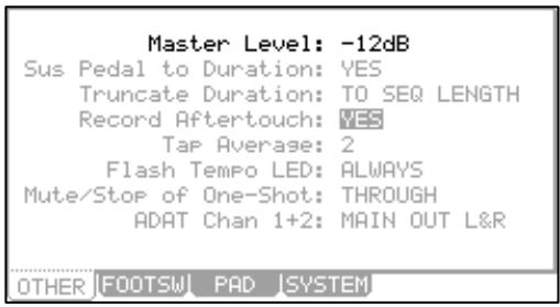
The MPC5000 can output up to 64 sounds simultaneously. There is a great difference in the level when you are playing single sounds or playing all 64 sounds at once. If you increase the value in the 'Master level' field, you can increase the entire level of the MPC5000 to create a more powerful audio output with less noise. However, if you playback many sounds at the same time, the level may be overloaded, which may cause distortion. If you decrease the value in the 'Master level' field, you can prevent distortion when you play more complicated sequences. You may find, however, that less complex sequences will benefit from increasing this value, as this will allow for more headroom, allowing for a punchier sound. Set the appropriate value in the 'Master level' field depending on the application.
Tap Average
This parameter determines how many taps will be used to average the tempo when tapping on the [TAP TEMPO] button.
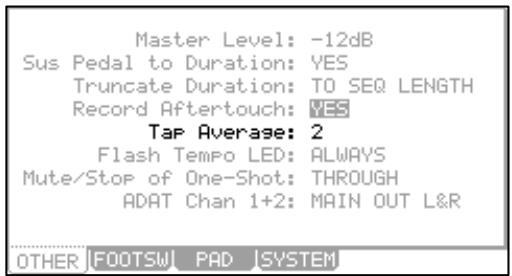
■ Flash Tempo LED
The Tap Tempo LED can be set to continuously flash, or only flash when tap tempo is in use. To adjust the Flash Tempo LED parameter, do the following:
- Press [MODE] and [PAD 9] to enter OTHER mode.
- Select the 'Flash Tempo LED' and select 'ALWAYS' or 'WHEN PRESSED'.
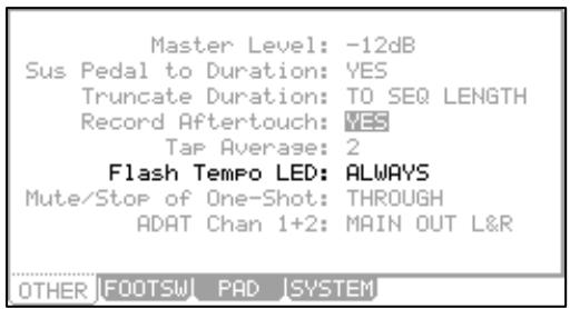
Mute / Stop of One-Shot Samples
The behavior of one-shot samples is selectable. To choose whether or not one-shot samples play after stop is pressed, or the track is muted, do the following:
- Press [MODE] and [PAD 9] to enter the OTHER page.
- Select the MUTE/STOP OF ONE-SHOT SAMPLES field, and select the desired Behavior
THROUGH
One shot samples are always played until sample end.
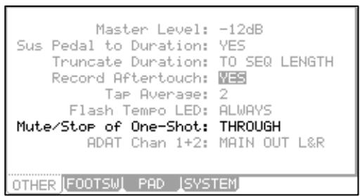
IMMEDIATE
One shot samples are stopped immediately when pressing stop or muting the pad.
Setting the ADAT Digital Output
Normally, the ADAT output follows the chart below:
| ADAT Channel | Output |
| 1 | STEREO OUT L |
| 2 | STEREO OUT R |
| 3 | MIX OUT 3 |
| 4 | MIX OUT 4 |
| 5 | MIX OUT 5 |
| 6 | MIX OUT 6 |
| 7 | MIX OUT 7 |
| 8 | MIX OUT 8 |
| Master Level: -12dB Sus Pedal to Duration: YES Truncate Duration: TO SEQ LENGTH Record Aftertouch: YES Tap Average: 2 Flash Tempo LED: ALWAYS Mute/Stop of One-Shot: THROUGH ADAT Chan 1+2: MAIN OUT L&R |
| OTHER |EOOTSW | PAD | SYSTEM | |
However, by setting the value of parameter 'ADAT Chan 1+2' to ASSIGN OUT 1&2, this will allow all eight of the assignable mix outs to be sent through the [ADAT OUT] port.
Using the Footswitches
You can connect up to 2 foot switches to the MPC5000 and assign several functions (ex. Start/Stop a sequence, etc...) to them.
- Connect a foot switch to the MPC5000's FOOTSWITCH jack.
- Press the [MODE] button, and then the [PAD 9] (OTHER) to enter OTHER mode.
- Press the [F2] (FOOTSW) button.
This brings up the FOOTSW page, where you can make settings for the foot switch.
- Select the function to assign to Footswitch 1 in the 'Footswitch 1' field, and the function to assign to Footswitch 2 in the 'Footsw
You can select the following functions.
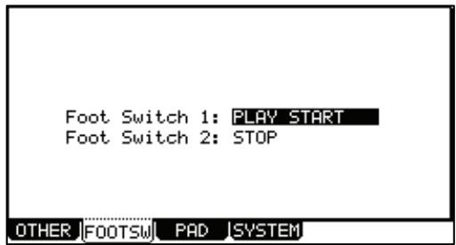
PLAY START
The Footswitch will act the same as pressing [PLAY START] button.
PLAY
The Footswitch will act the same as pressing [PLAY] button.
STOP
The Footswitch will act the same as pressing [STOP] button.
PLAY/STOP
When you step on the Footswitch in stop mode, the MPC5000 will start playback at the current stopped position.
When you step on the switch in play mode, the MPC5000 will stop playback.
PLAY START/STOP
When you step on the Footswitch in stop mode, the MPC5000 will start playback from the beginning.
When you step on the switch in play mode, the MPC5000 will stop playback.
REC+PLAY
The footswitch will act the same as when you press the [REC] button and the [PLAY] button simultaneously (recording).
OVER DUB+PLAY
It works the same as pressing the [OVER DUB] and [PLAY] button simultaneously (overdub).
REC/PUNCH
When you step on the switch in stop mode, the MPC5000 will start playback.
When you step on the switch in play mode, the MPC will start recording.
In RECORD mode, the footswitch will start playback.
OVER DUB/PUNCH
When you step on the switch in stop mode, the MPC5000 will start playback.
When you step on the switch in play mode, the MPC will start over dubbing.
In overdub mode, the footswitch will start playback.
TAP TEMPO
Pressing the footswitch will work as if the [TAP TEMPO] button was pressed.
PAD 1-16
Pressing the footswitch will work as if the selected pad was played.
F1-F6
Pressing the footswitch will work as if the corresponding function button was pressed.
PAD BANK A-D
Pressing the footswitch will work as if the corresponding Pad Bank button was pressed.
NOTE REPEAT
Pressing the footswitch will work as if the [NOTE REPEAT] button was pressed.
■ Adjustment of Pad Sensitivity and Velocity Curve
Each time you hit a pad, the MPC5000 determines how hard you hit the pad, and converts this to a MIDI Velocity value. This parameter is used to determine the strength/weakness of the internal sound during playback, as well as other system parameters that the velocity may be mapped to.
If you find it difficult to achieve a comfortable velocity range for your playing style, e.g. you can not get a velocity of 127 even you hit the Pad very hard, or vice versa, you get velocity 127 easily even you hit the Pad softly, you can adjust the Pad Sensitivity and the velocity curve as desired. The Pad sensitivity and the Velocity curve can be adjusted for each Pad separately.
- Press the [MODE] button and then the [PAD 9] (OTHER).
The Other page will be displayed.
- Select the PAD page by pressing [F3] (PAD).
- Select the Pad you wish to adjust the Pad Sensitivity by hitting it.
The selected Pad Number will be displayed in the 'Pad' field. The number of the current Pad sensitivity and the current Velocity curve will be displayed in 'Pad Sensitivity' field and 'Velocity Curve' field. Velocity and Aftertouch will be displayed in meters on the right side of the screen.
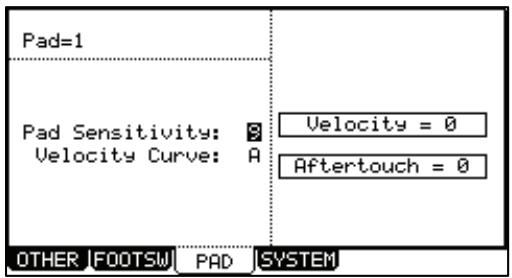
- Select the 'Pad Sensitivity' field and adjust the pad sensitivity number as you hit the Pad.
If the Pad sensitivity number is set to a low value, it's harder to get a high velocity value even if you hit the Pad hard. If the Pad sensitivity number is set to a high value, it may become too easy to get high velocities even when hitting the Pad softly.
- Select the 'Velocity curve' field and adjust the Velocity curve while hitting the Pad.
The velocity curve maps the strength of hitting the Pad to MIDI velocity data. If the Velocity response is not enough even with a range hard/soft Pad hits, try switching the velocity curve from A-B-C-D.
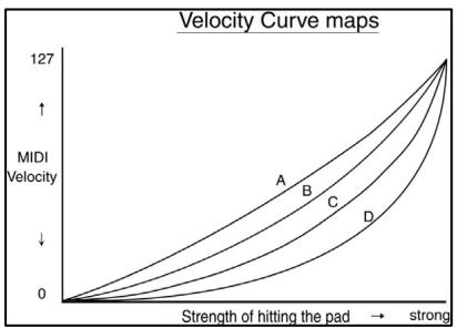
SYSTEM
This page displays important system information about your MPC5000. To access this page, press [F4] (SYSTEM) while in OTHER mode.
Version
The MPC 5000's operating system is upgradeable and allows us make changes to existing features after it has left the factory floor. To make sure you have the latest version of the OS, you can check the version of the OS in Other mode.
To confirm you have the latest operating system, check the support section of http://www.akaipro.com.
CPU Usage
This parameter displays how much system resources are being used.
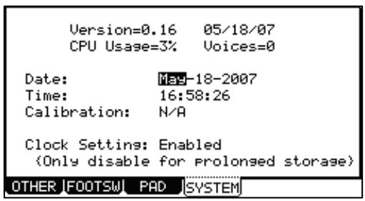
Voices
This parameter displays how many voices are currently being used. The MPC5000 can play up to 64 voices simultaneously.
Date
This parameter sets the date for the internal clock.
Time
This parameter sets the MPC5000's internal clock.
Calibration
This parameter is used if the clock drifts slightly over long periods of time. (For example, over a month).
Clock Setting
This enables or disables the internal clock. The internal clock should not be disabled unless the MPC5000 is going to be stored over a long period of time.
■ Initialize To Factory Default
The global settings found in the MPC5000 (listed below) are saved to the internal Flash Memory and stored when the MPC5000 is turned off. You can re-initialize the Factory Preset settings using the following procedure.
- Turn the MPC5000 on while holding the [ERASE] button.
- Release the [ERASE] button after the display shows [MPC5000 (##MB installed)].
Now the MPC5000 is reset to the Factory Preset settings. The following global settings are stored in the MPC5000:
Timing Correct (all values)
Record Aftertouch
Click/Metronome (all values)
Tap average
Step Edit Options (Auto Step Increment, Record Note Duration)
Flash Tempo LED
Active track receive channel
Mute/Stop of One Shot Samples
Soft thru
ADAT Channel
Sequence Change by Program Change
Footswitches
Pad to Internal Sounds
Pad Sensitivity and Curve
Sync in
Autologoad
Sync out
Mute Options (Record, Play, Instant)
Master level
Mixer Automation Record Options
Sustain pedal to duration
Record Sample Options
Truncate duration
Record Aftertouch
How to Upgrade the MPC5000
IMPORTANT: THIS UPDATE PROCEDURE WILL ERASE ALL USER DATA.
Please save all of your songs, patterns, and samples to a CF card or to your computer using USB before proceeding.
- Save the new OS file from the website to the ROOT of the CF card using your computer.
- Insert the CF with OS data into MPC5000.
- Turn the power on while holding down the [2] and [3] buttons. The update will start automatically.
- Because of all the new features and parameters, it will be necessary to re-initialize the MPC5000 after the upgrade procedure is complete. To do so, turn the MPC5000 off, hold down the [ERASE] button and turn the unit back on.
Chapter 21: Specifications
General
Display: 240 × 128 dot graphic LCD w/back light
Memory Card Slot: Compact Flash (The size of the compact flash card that MPC5000 can handle is from 32MB to 2GB)
Dimensions: 18in x 16 1/16 x 3 3/8 (6 7/8 with screen at max.)
Weight: 18.2 lbs
Power Requirement: 50w
Sound Generator
Sampling rate: 44.1kHz
Memory capacity: 64MB standard, expandable to 192MB
Recording time: 12m 48sec. (64MB, MONO), 38m24sec. (192MB, MONO)
Memory expansion slot: 1 x for optional EXM-E3
Data format: 16-bit linear
Polyphony: 64
Dynamic filtering: 1 State Variable Filter per voice (up to 8 pole, depending on type)
Filter types: LOW PASS, BAND PASS, HIGH PASS, BAND BOOST, BAND STOP, ANALOG MODELING, VOCAL FORMANT
Preset sound memory: 16 MB
Number of programs: 128
Effects
Effects: 4 stereo busses with 2 stereo effects per buss, and Master effect
Master effect: 4 band EQ, Compressor
Sequencer
Maximum events: 100,000 notes
Resolution: 960 parts per 1/4-note
Sequences: 99
Tracks per sequence: 64
MIDI output channels: 64 (16 channels x 4 outputs)
Song mode: 20 songs, 250 steps per song
16 (velocity and pressure sensitive)
Drum pad banks: 4
Sync mode: MIDI clock, MIDI Time Code
Transport Controls: MIDI Machine Control
Inputs/Outputs
Record input (L and R): MIC/ 1/4-inch Combo x 2 balanced -40dBu, input impedance 11k ohms; RCA with PHONO preamp,
Max. Input level: +10dBu
Digital input: RCA-pin x 1 S/PDIF
Stereo output (L and R): 1/4-inch phone x 2 balanced +11dBu, output impedance 1k Ohms,
Max. output level: +22dBu
8 individual outputs: 1/4-inch phone x 8 balanced +11dBu, output impedance 1k Ohms,
Max. output level: +22dBu
Phones output: 1/4-inch stereo phone x 1, 200mW / 100 ohms
Digital output: RCA-pin × 1 S/PDIF
ADAT Optical × 1 (8 Channels)
MIDI inputs: 5-pin DIN x 2
MIDI outputs: 5-pin DIN x 4
USB: Slave connector x 1, USB MASS STORAGE CLASS support
(Windows 2000/Me/XP or later version, or Mac OS 9.x/10.x or later version.)
Footswitches: 1 / 4 -inch × 2
Standard accessories
Standard accessories: Power cable, Operator's manual
■ Options
EXM-E3: 128MB expansion memory card (Upgrades unit to 192MB total)
CDM-25 CDR/DVD Drive
Data Compatibility
MPC1000: SEQ,WAV,PGM
MPC2000/2000XL: SEQ, WAV, SND, PGM (Most parameters of PGM file can be loaded.)
MPC4000: SEQ, WAV, PGM (DRUM program only. Only note assign and tune are loaded.)
MPC3000: SND (THRU Computer)
Z4/Z8: SEQ, WAV, PGM (DRUM program only. Only note assign and tune are loaded.)
S5000/6000: WAV only (THRU Computer)
S1000/3000: No compatibility
MIDI Implementation Chart
Akai Professional, LLC
Model: MPC5000 (Sampler Section)
| Function | Transmitted | Recognized | Remarks | |
| Basic Channel | Default | X | 1-16 | |
| Changed | X | 1-16 | ||
| Mode | Default | X | 1 | |
| Messages | X | X | ||
| Altered | X | X | ||
| Note Number | X | 35-98 | ||
| True Voice | X | 35-98 | ||
| Velocity | Note On | X | O | |
| Note Off | X | X | ||
| Aftertouch | Poly | X | X | |
| Channel | O | O | Used in Note Repeat | |
| Pitch Bend | X | O | Synth Programs Only | |
| Control Change | 0-127 | O | O | Q-LINKS |
| Program Change | X | 0-127 | ||
| System Exclusive | X | X | ||
| System Common | :Song Position | X | X | |
| :Song Select | X | X | ||
| :Tune | X | X | ||
| System Real Time | Clock | X | X | |
| Commands | X | X | ||
| Aux Messages | :Local On/Off | X | X | |
| :All Notes Off | X | O | ||
| :Active Sense | X | X | ||
| :Reset | X | X | ||
| Notes: | ||||
Mode 1: OMNI ON, POLY Mode 2: OMNI ON, MONO
O:Yes
Mode 3: OMNI OFF, POLY Mode 4: OMNI OFF, MONO
X: No
Akai Professional, LLC
Model: MPC5000 (Sequencer Section)
| Function | Transmitted | Recognized | Remarks | |
| Basic Channel | Default | 1-16 | 1-16 | |
| Changed | 1-16 | 1-16 | ||
| Mode | Default | 3 | 1 | |
| Messages | X | X | ||
| Altered | X | X | ||
| Note Number | 0-127 | 0-127 | ||
| True Voice | 0-127 | 0-127 | ||
| Velocity | Note On | O | O | |
| Note Off | X | X | ||
| Aftertouch | Poly | O | O | |
| Channel | O | O | ||
| Pitch Bend | O | O | ||
| Control Change | 0-127 | O | O | |
| Program Change | O | O | ||
| True # | 0-127 | 0-127 | ||
| System Exclusive | O | O | ||
| System Common | :Song Position | O | O | |
| :Song Select | X | X | ||
| :Tune | X | X | ||
| System Real Time | Clock | O | O | |
| Commands | O | O | ||
| Aux Messages | :Local On/Off | X | X | |
| :All Notes Off | O | X | ||
| :Active Sense | X | X | ||
| :Reset | X | X | ||
| Notes: | ||||
Mode 1: OMNI ON, POLY Mode 2: OMNI ON, MONO
O:Yes
Mode 3: OMNI OFF, POLY Mode 4: OMNI OFF, MONO
X: No
Index
1
16 levels · 2 , 71, 72
A
Active track receive channel · 171 , 178
ADAT·8,11,176,180
Aftertouch·36,125,177,181,182
Amount · 38 39,110,136
Arpeggiator · 6 ,15,129,130,131
Assign to pad · 88, 155
Attack·44,51,109,110,118,121,123,137,142,143
Auto step increment · 47,52,53
Autoload·105,116,160,161,178
Automation·69,70,81,151
B
Bars·19,27,29,30,56,63
C
Channel pressure event · 46
Copies · 38,40
Current tempo·44
D
Decay · 44 ,51,109,110,118,121,123,144,145
Direct recording · 87
Drum pad · 179
Duration of recorded notes · 47 , 53
DVD·7,159,180
E
Edit·37,38,39,40,41,43,47,49,52,63,64,65,66,67,91 92,94,95,96,97,99,101,118,120,122,123,124,147 178
End·63,64,65,89,90,91,98,99,102
ENV·115
Erase·23,24,47
Event·43,44,45,46,47,49,50,51,52,163,164,165
Event list · 46 ,51,52
Event time · 43 ,52
Exclusive data event · 46
F
Filter·44,45,51,109,110,111,112,113,118,120,124 125,137,164,179
Filter envelope · 109
Footswitch · 12, 176
Freq·110,111,137
Full level · 71
G
Gain·65,137,140,141
1
Ignore tempo change events in · 58
In play·25
Input · 2,8,10,70,82,83,85,86,87,142,143,153,158, 171,180
Input thru · 82 153,158
K
key·14,25,36,38,41,45,47,51,53,71,74,86,99,102, 103,108,109,110,121,123,130,173,176
L
Latch·130
Layer · 44 ,51
Lfo·119
Load·153,156,157,158
Lp·102, 103
Lv1 · 106,109,110
M
Main page · 3 ,21,88
Make new folder · 151
Master level · 15 ,85,175,178
Memory card · 159
Mic · 8 ,10
MIDI Machine Control · 169, 179
MIDI Time Code · 167, 168, 169, 179
Mixdown·69,70
Mixer automation · 70
MMC·4,169
ModW·124,125
Modwheel · 124, 125
Monitor·86,87
MTC·19,168
Multi · 140
Mute group · 112
N
Normalize · 66
Note event · 49
Note repeat·26
Note variation · 44 , 51, 72
Note variation value · 44
Now·18,19,21,26,43,46,47,49,50,52,55,61,63,72,74 75,94,109,130,160,168,178
Numeric keys · 102
0
Out · 8 ,22,65,82,102,145,146
P
Pad event · 49
Parameter·23,163,164,165
Pgm·105,108,110,113,116,125,126
Pitch shift · 96
Poly pressure event · 46
Program·14,20,31,32,35,45,74,77,79,88,99,105,112 113,115,116,117,118,122,124,125,126,129,150,151 156,181,182
R
Ram·9
Range·37,38,39,40,49,52,63,107,124,164
Rate·25,113,123,136,137,146,168
Record Aftertouch·36
Region·98,99,101
Replace same files · 151 , 152, 157
Replace same files in memory · 157
Replace same samples · 150 , 156
Replace same samples in memory 156
Reps·56, 57
Res·111,118,120,137,139,142
S
Sample · 10 , 13, 14, 15, 20, 34, 77, 78, 89, 91, 92, 93, 94, 95, 96, 97, 98, 100, 102, 105, 106, 107, 108, 109, 110, 112, 115, 126, 150, 151, 152, 155, 160, 171
Save·67,70,150,151,160,178
Send level · 133
Sequence·2,13,18,20,21,22,27,28,29,30,31,32,36 40,41,56,58,70,72,75,88,94,147,151,157
Sequence list · 75
Shift timing·39
Soft thru 170, 178
Solo·72,73
Song·13,55,56,57,58,59,61,62,63,66,67,179,181,182
Sq·38,39,40
St·63,64,89,90,99
Step·21,28,43,47,49,52,53,55,56,58,130,169,173 174,178
Step list · 55,56
Sustain pedal · 36 ,178
Sustain pedal to duration · 178
Swing·24,25,130
Sync in 167, 168, 169, 178
Sync out·167,168,169,178
Timing correct · 24, 26, 43, 51
Tr·23
Track·2,20,31,32,33,34,41,58,61,62,63,64,66,67,68, 69,72,73,74,80,81,86,88,129,151,171
Track list · 72
Track mute · 2 ,73
Track type · 88
Truncate duration · 31 , 178
Tune·44,51,92,100,106,108,165,181,182
V
V·44,45,51,106,108,109,110,111
VCA·122,142
VCF·115,120
VCO·115,117,118,119
Voice overlap · 113
W
Window·7,25,87,107