
G92TT - Guitar effects pedalboard ZOOM - Free user manual and instructions
Find the device manual for free G92TT ZOOM in PDF.
| Brand | ZOOM |
| Model | G92TT |
| Product Type | Guitar effects pedalboard |
| Power Supply | 15 V DC, 1.5 A AC adapter (model ZOOM AD-0012) |
| Sampling Frequency | 96 kHz |
| Audio Resolution | 24 bits, internal processing 32 bits |
| Number of Patches | 200 (100 presets + 100 user) |
| Number of Banks | 10 per group (groups A, b, U, u) |
| Expression Pedals | 2 built-in (Z pedal on the right, sensitive to horizontal movement) |
| Accelerator | Tube and solid-state circuit, continuously adjustable |
| Energizer | Tube circuit to warm up the output signal |
| Effect Modules | COMP, WAH/EFX1, EXT LOOP, ZNR, PRE-AMP, EQ, CABINET, MOD/EFX2, DELAY, REVERB, TOTAL |
| Connectivity | 6.35 mm input jack, L/MONO and R outputs, SEND/RETURN effects loop, MIDI IN/OUT jacks, USB, headphone |
| Built-in Tuner | Chromatic and other types (guitar, bass, open tuning, etc.) |
| Operating Modes | Play, Manual, Edit, Store, Bypass/Mute |
| Cleaning | Soft dry cloth, do not use solvents or abrasive products |
| Safety | Use only the specified adapter; do not expose to moisture, shock, or extreme temperatures; do not open the case |
| Computer Compatibility | USB audio interface (ASIO for Windows, Core Audio for Mac) |
Frequently Asked Questions - G92TT ZOOM
User questions about G92TT ZOOM
0 question about this device. Answer the ones you know or ask your own.
Ask a new question about this device
Download the instructions for your Guitar effects pedalboard in PDF format for free! Find your manual G92TT - ZOOM and take your electronic device back in hand. On this page are published all the documents necessary for the use of your device. G92TT by ZOOM.
USER MANUAL G92TT ZOOM
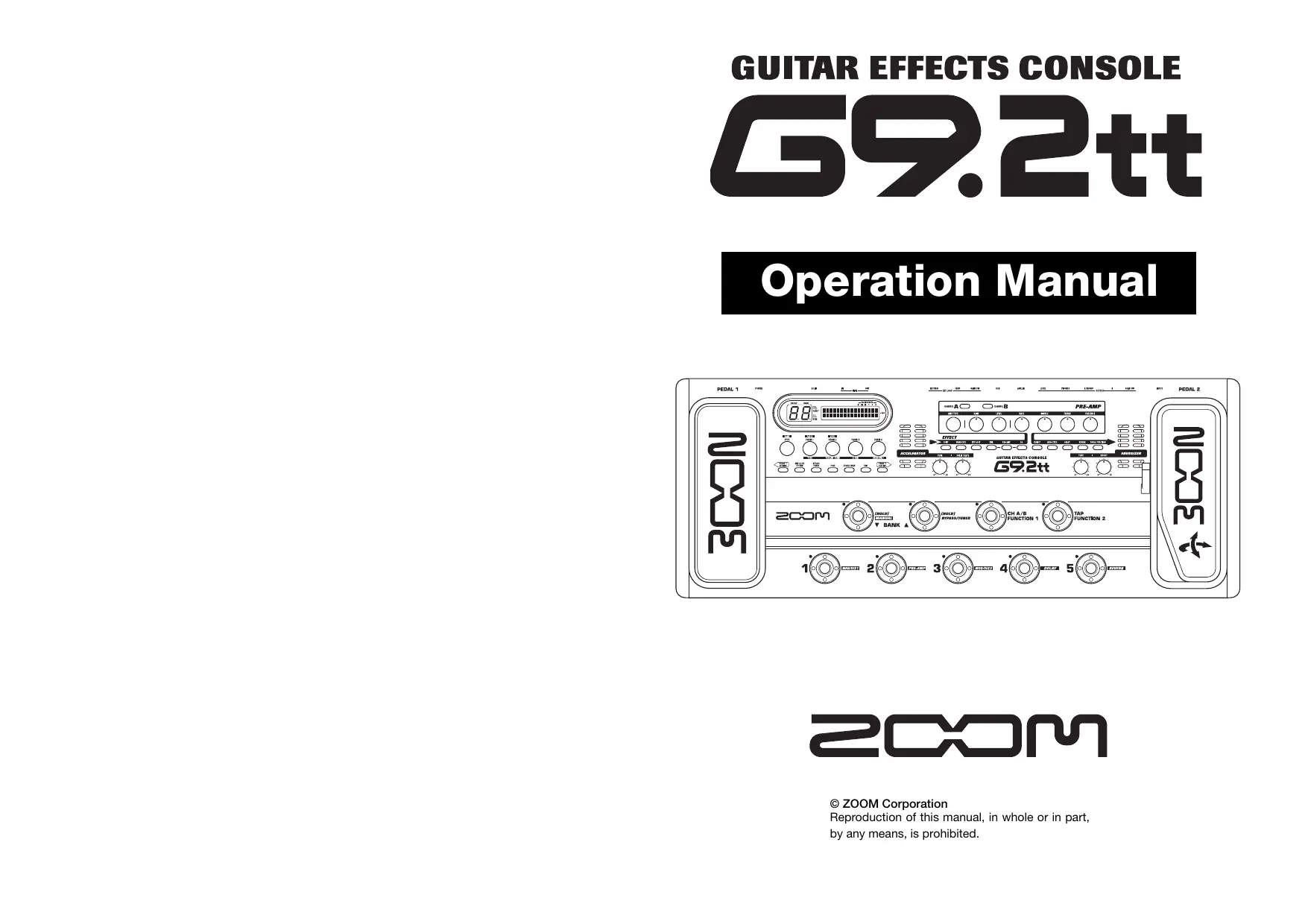
GUITAR EFFECTS CONSOLE
69.2tt
Operation Manual
200m
© ZOOM Corporation
Reproduction of this manual, in whole or in part,
by any means, is prohibited.
SAFETY PRECAUTIONS Usage Precautions
SAFETY PRECAUTIONS
In this manual, symbols are used to highlight warnings and cautions for you to read so that accidents can be prevented. The meanings of these symbols are as follows:

Warning
This symbol indicates explanations about extremely dangerous matters. If users ignore this symbol and handle the device the wrong way, serious injury or death could result.

Caution
This symbol indicates explanations about dangerous matters. If users ignore this symbol and handle the device the wrong way, bodily injury and damage to the equipment could result.
Please observe the following safety tips and precautions to ensure hazard-free use of the G9.2tt.

Power requirements
- Be sure to use only an AC adapter which supplies 15 V DC, 1.5A (Zoom AD-0012). The use of an adapter other than the specified type may damage the unit and pose a safety hazard.
- Connect the AC adapter only to an AC outlet that supplies the rated voltage required by the adapter
- When disconnecting the AC adapter from the AC outlet, always grasp the adapter itself and do not pull at the cable.
- During lightning or when not using the unit for an extended period, disconnect the AC adapter from the AC outlet.
- Do not pinch the power cord, bend it forcefully, or place heavy objects on the power cord.

Environment
To prevent the risk of fire, electric shock or malfunction, avoid using your G9.2tt in environments where it will be exposed to:
- Extreme temperatures
- Heat sources such as radiators or stoves
High humidity or moisture - Excessive dust or sand
-
Excessive vibration or shock
-
Keep a minimum distance of 5cm around the unit for sufficient ventilation.
- Do not impede the ventilation openings with objects such as newspapers or curtains.

Handling
- Never place objects filled with liquids, such as vases, on the G9.2t since this can cause electric shock.
- Do not place naked flame sources, such as lighted candles, on the G9.2tt since this can cause fire.
-
The G9.2tt is a precision instrument. Do not exert undue pressure on the keys and other controls. Also take care not to drop the unit, and do not subject it to shock or excessive pressure.
-
Take care that no foreign objects (coins or pins etc.) or liquids can enter the unit.

Connecting cables and input and output jacks
You should always turn off the power to the G9.2tt and all other equipment before connecting or disconnecting any cables. Also make sure to disconnect all connection cables and the power cord before moving the G9.2tt.

Alterations
Never open the case of the G9.2tt or attempt to modify the product in any way since this can result in damage to the unit.

Volume
Do not use the G9.2tt at a loud volume for a long time since this can cause hearing impairment.
Usage Precautions
Electrical interference
For safety considerations, the G9.2tt has been designed to provide maximum protection against the emission of electromagnetic radiation from inside the device, and protection from external interference. However, equipment that is very susceptible to interference or that emits powerful electromagnetic waves should not be placed near the G9.2tt, as the possibility of interference cannot be ruled out entirely.
With any type of digital control device, the G9.2tt included, electromagnetic interference can cause malfunctioning and can corrupt or destroy data. Care should be taken to minimize the risk of damage.
Cleaning
Use a soft, dry cloth to clean the G9.2tt. If necessary, slightly moisten the cloth. Do not use abrasive cleanser, wax, or solvents (such as paint thinner or cleaning alcohol), since these may dull the finish or damage the surface.
Please keep this manual in a convenient place for future reference.
- MIDI is a registered trademark of Association of Musical Electronics Industry(AMEI).
Contents
SAFETY PRECAUTIONS Usage Precautions 2
Features 4
Terms Used in This Manual 5
Controls and Functions 6
Getting Connected 8
Power-On 9
Quick Guide 1 (Play Mode/Manual Mode Operation) 10
Quick Guide 2 (Edit Mode/Store Mode Operation) 12
Selecting Patches for Playing (Play Mode) 14
Panel display 14
Selecting a patch 14
Adjusting the sound 15
Using the Accelerator 16
Using the Energizer 17
Switching Modules On and Off With Your Foot During Play (Manual Mode) 19
Using the Internal Tuner (Bypass/Mute Condition) 21 Using the chromatic tuner 21
Using other tuned types 22
Changing the Sound of a Patch (Edit Mode) 24
Patch configuration 24
Basiceditmodesteps 24
Changing a patch name 27
Storing Patches and Banks (Store Mode) 28
Storing/swapping patches 28
Storing/swapping banks 29
Returning patches to factory default condition 29
Using the Expression Pedals 31 About the expression pedals 31
Assigning control targets to expression pedal 1 32
Assigning control targets to expression pedal 2 33
Adjusting the expression pedals 35
Using the Function Foot Switches 38 Specifying the tempo for a patch 39
Using the Effect Loop 41
MIDI Usage Examples 43
What you can do with MIDI 43
Selecting the MIDI channel 43
Sending and receiving patch switching information via MIDI (program change)
Sending and receiving pedal/swi tch/ key operation information via MIDI (control change) 47
Sending and receiving G9.2tt internal data via MIDI 50
Other Functions 52 Using the ARRM function 52
Using the G9.2tt as audio interface for a computer 54
Muting the direct output when using a USB connection 55
About the editor/librarian software 56
Adjusting the display contrast 56
Linking Effects 57
Switching between live performance sound and direct recording sound 57
Using the Amp Select Function 58
Changing the insert position of the pre-amp section and WAH/EFX1
module 58
Effect Types and Parameters 60
How to read the parameter table 60
COMP module 61
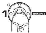
WAH/EFX1 module 61
EXT LOOP (external loop) module 64
ZNR module 64
PRE AMP module 65
EQ module 67
CABINET module 67
MOD/EFX2 module 67
DELAY module 72
REVERB module 73
TOTAL module 75
Troubleshooting 76
Specifications 77
MIDI implementation chart 78
- Microsoft and Windows XP are registered trademarks of Microsoft Corporation.
- Macintosh is a registered trademark of Apple Computer.
- All other trademarks, product names, and company names mentioned in this document are the property of their respective owners.
- Manufacturer names and product names mentioned in this document are trademarks or registered trademarks of their respective owners. The names are used only to illustrate sonic characteristics and do not indicate any affiliation with ZOOM CORPORATION.
Features
Thank you for selecting the ZOOM G9.2tt (simply called the "G9.2tt" in this manual). The G9.2tt is a sophisticated Multi Effect Processor with the following features.
- Latest technology for top performance
Excellent sound quality is assured by signal processing featuring 96kHz / 24 bit sampling and internal 32-bit processing. Frequency response remains flat to 40kHz , and input converted noise is an amazing 120dB or better.
Ready-to-use patches
Effect module combinations and settings can be stored and recalled as "patches". The G9.2tt offers 100 patches in the read-only preset groups, plus 100 patches in the user groups which can be freely rewritten, resulting in a total of 200 choices. Send / return level and on/off settings of external effects connected via the SEND/RETURN jacks can also be stored as part of a patch.
- Great for stage work or direct recording
The pre-amp section features two channels, and each distortion type has two dedicated algorithms, one for live playing and one for direct recording. The CABINET effect simulates amp and mic recording characteristics, and the algorithm is automatically switched according to the CABINET on/off setting. An amp select feature matches the sound to the amp you are using. Connecting the G9.2tt to the power amplifier input of the guitar amp is no problem: simply set the -10dBm / +4 dBm switch to the +4 dBm position.
Built-in tuner supports special tuning requirements
In addition to the standard auto-chromatic tuner, various other tuning methods are possible. The tuner also allows easy tuning on stage without producing sound.
- Two expression pedals built in as standard
Adjust effect tone or volume in real time with the two expression pedals that are built right into the unit. The right-side pedal in particular deserves attention: the Z-Pedal that senses not only vertical but even horizontal movement. Step into the next dimension of pedal play and discover a whole new world of possibilities.
- Tube powered Accelerator and Energizer
The analog input stage features an Accelerator that lets you freely mix the signals amplified by a vacuum tube circuit and a solid-state circuit. In this way, you can add characteristic tube compression and distortion to a clean sound. In addition, the G9.2tt also features an Energizer that processes the analog output signal to produce that characteristic warm and dynamic sound that is the hallmark of a tube amplifier.
- Programmable function foot switches
Two user-programmable function foot switches further enhance flexibility and let you optimize the unit for any application. Use them to switch pre-amp channels, set the delay time, turn hold delay on and off, or for various other tasks.
Please take the time to read this manual carefully, in order to get the most out of your G9.2tt and to ensure optimum performance and reliability.
Terms Used in This Manual
This section explains some important terms that are used throughout the G9.2tt documentation.
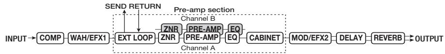
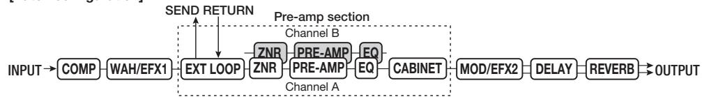
■ Effect module
As shown in the illustration below, the G9.2tt can be thought of as a combination of several single effects. Each of these is referred to as an effect module. The G9.2tt offers a compressor effect module (COMP), amp simulator/distortion effect module (PRE-AMP), external effect loop control module (EXT LOOP), and more. Parameters such as effect intensity can be adjusted for each module individually, and modules can be switched on and off as desired. The five modules EXT LOOP, ZNR, PRE-AMP, EQ, and CABINET operate as a virtual preamplifier which is controlled with the knobs and keys on the pre-amp section of the panel.
■ Effect type
Most effect modules comprise several different effects which are referred to as effect types. For example, the modulation effect module (MOD/EFX2) comprises chorus, flanger, pitch shifter, delay, and other effect types. Only one of these can be selected at any time.
■ Effect parameter
All effect modules have aspects that can be controlled. These are called effect parameters, adjusted with the parameter knobs 1 - 4 on the panel. When thinking of an effect module as a compact effect, the parameters change the tone and effect intensity similar to the knobs on the device.
Patch
In the G9.2tt, effect module combinations are stored and called up in units referred to as patches. A patch comprises information about the on/off status of each effect module, about the effect type used in each module, and about effect parameter settings. Expression pedal settings and tempo settings are also stored for each patch individually.
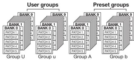
Bank and group
Patches are organized in user groups (U, u) which can be modified, and in preset groups (A, b) which are read-only. Since each group comprises
50 patches, groups A, b, U, and u offer a total of 200 patches.
In the G9.2tt, patches are called up five at a time and selected with the foot switches. These five patches are together referred to as a bank. There are ten banks in a group, numbered 0 through 9.
■ Modes
The G9.2tt has five different operation modes, as listed below.
- Play mode
In this mode, patches can be selected and played. This is the default mode of the G9.2tt that is always active when power is turned on.
- Manual mode
In this mode, you play your instrument while using the foot switches to turn modules on and off.
Edit mode
In this mode, the effect parameters of a patch can be edited (changed).
- Store mode
This mode serves for storing edited patches. It also allows changing the store positions of patches.
- Bypass/mute mode
When the G9.2tt is in the bypass condition, effect processing is temporarily turned off and only the original sound is heard. In the mute mode, all sound is turned off. The built-in tuner can be used in either condition.
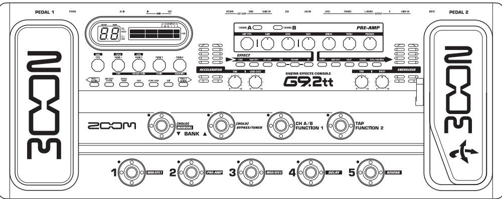
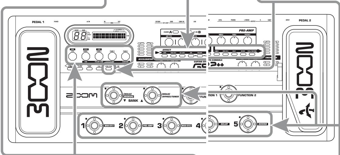
Controls and Functions
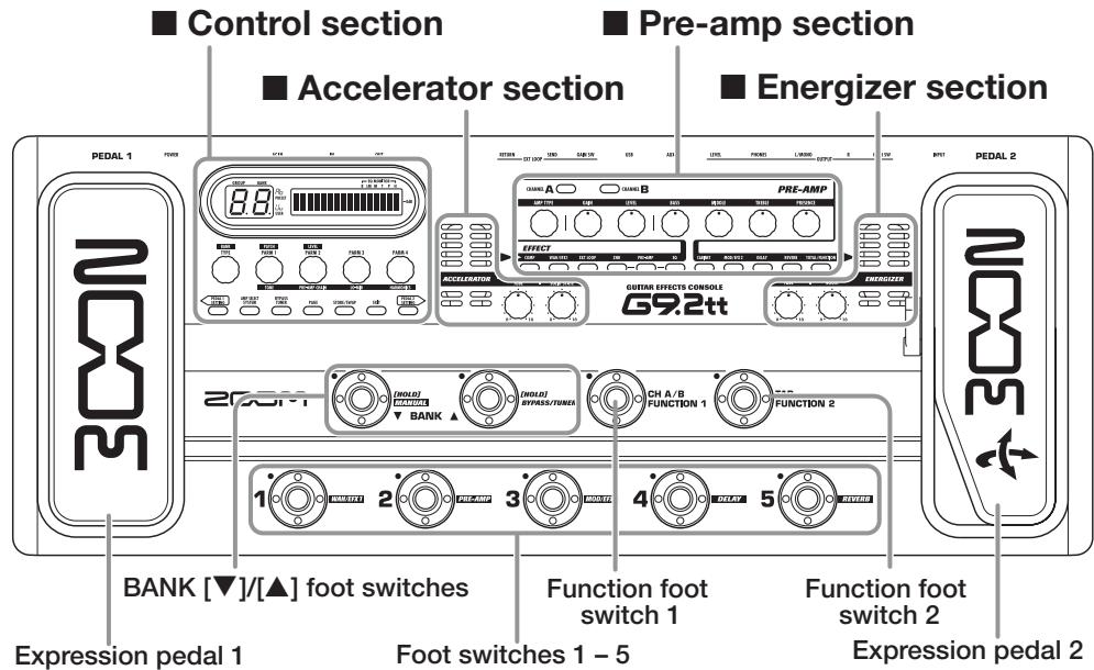
Top panel
Rear panel
Control section
Pre-amp section
Accelerator section
■ Energizer section
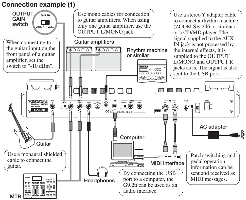
Getting Connected
Refer to the examples shown below when making connections.
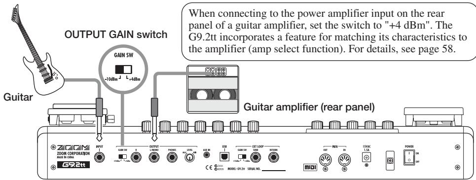
Connection example (2) (Direct connection to power amplifier input on amp)
Connection example (3) (External effect connection)
When an external effect is connected to the SEND/RETURN jacks, settings such as effect on/off and send/return level can be stored as part of a patch. For details, see page 41.
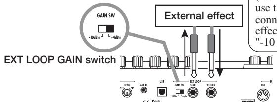
When connecting to an effect that has a rated input level of +4dBm (rack-mount effect or similar), use the +4dBm setting. When connecting to an instrument effect or a compact effect, use the -10dBm setting.
Power-On
The steps for turning on the G9.2tt are described below.
- Make sure that any connected guitar amplifier is turned off.
In addition, fully turn down the volume control at the guitar amplifier.
- Plug the AC adapter into an AC outlet and plug the cable from the adapter into the AC IN connector of the G9.2tt.
- Use a monaural cable to connect the guitar to the INPUT jack of the G9.2tt.
- Use a monaural cable to connect the OUTPUT L/MONO jack to the guitar amplifier (when using one amplifier) and the OUTPUT R jack to the second guitar amplifier (when using two amplifiers).
HINT
To monitor with headphones, plug the headphone cable into the PHONES jack of the G9.2tt.
- Turn power on in the following order: G9.2tt guitar amplifier(s)
NOTE
Proceed with care when powering up the system. If you turn on power to the G9.2tt while the guitar amplifier is already on, there is a risk of hearing damage and damage to the speakers.
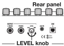
- Play your guitar and adjust the volume control on the guitar amplifier, on the guitar, and the LEVEL knob on the rear panel of the G9.2tt to obtain optimum listening volume.
HINT
The G9.2tt has a so-called "Amp Select" feature that lets you match the unit to various kinds of amplifiers. If necessary, select the appropriate setting for your amplifier the first time you use the G9.2tt ( p. 58).
- To shut down the system, turn power to the respective components off in the reverse order than during power-up.
HINT
When the OUTPUT GAIN switch on the rear panel is set to "-10 dBm" and the LEVEL knob is turned fully up, the G9.2tt has unity gain (output level is the same as input level).
Quick Guide 1 (Play Mode/Manual Mode Operation)
This section explains various basic steps, allowing you to use the G9.2tt right away.
1 Selecting a patch (play mode)
Immediately after power-on, the unit will be in play mode.
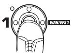
1. To select a patch, use foot switches 1 - 5.
You can switch patches within the same group/bank. The number of the currently selected patch can be checked by checking which foot switch LED (1 - 5) is lit.
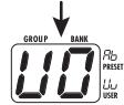
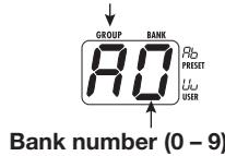
[Indication in play mode]
Group name/Bank number
![ZOOM G92TT - [Indication in play mode] - 1](/content/2025/01/152275/images/4aefcd3bb9888ba4ecf14b2311df57b799ba6242ccae97930166f8ec34375bb0.jpg)
Function foot switch 1 assignment
HINT
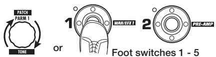
- You can switch patches within the same group/bank by turning parameter knob 1.
-
You can adjust the patch level (output level of the individual patch) by turning parameter knob 2.
-
To select a patch from another group/bank, use the BANK [ ] / [ ] foot switches to select the group/bank and then use foot switches 1 - 5.
HINT You can switch the group/bank by turning the [TYPE] knob.
Turning a module on and off with your foot (manual mode)
In manual mode, you can use foot switches 1 - 5 to switch a module on and off.
1. In play mode, keep the BANK [▼] foot switch depressed for more than one second.
The G9.2tt switches to manual mode.
NOTE
In manual mode, the foot switches do not select patches. However, the [TYPE] knob (group/bank selection) and parameter knob 1 (patch selection) function the same as in play mode. Note that when you switch a patch, the unit returns to play mode.
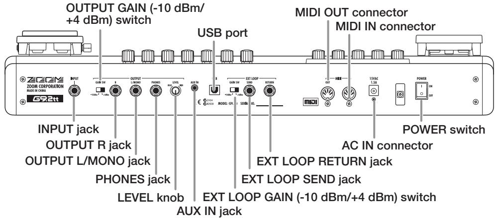
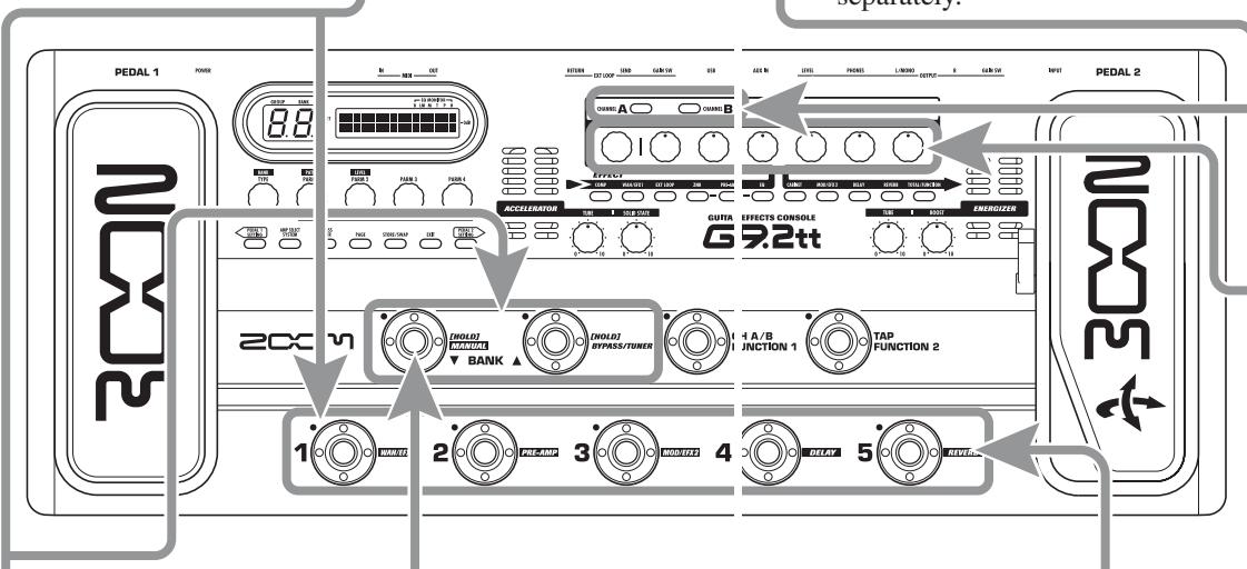
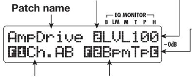
Pre-amp operation
The pre-amp section allows you to adjust distortion type, intensity, and EQ for two channels (A/B) separately.
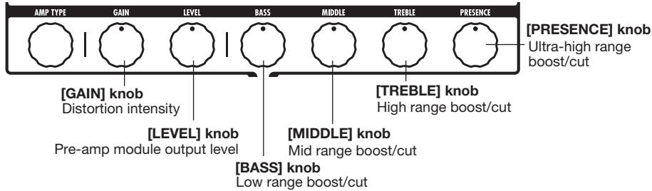
Distortion type [AMP TYPE] knob
[Pre-amp section]
Pre-amp
module
output level
[LEVEL] knob
Mid range
boost/cut
[MIDDLE] knob
Ultra-high
range boost/cut
[PRESENCE] knob
![ZOOM G92TT - [Pre-amp section] - 1](/content/2025/01/152275/images/deaa7cbe2434585378bc03fb49a81050382319029e50be954a482bbebd244112.jpg)
[GAIN] knob Distortion intensity
[BASS] knob Low range boost/cut
[TREBLE] knob High range boost/cut
1. Select the channel for which to make a setting with the [PRE-AMP A/B] keys.
The key light shows which channel is currently selected.
HINT You can switch between channel A and B with function foot switches 1 or 2 (→ p. 38).
2. Turn the knobs of the pre-amp section to make adjustments.
When you operate a knob, the name of the parameter and the current setting value appear on the display. To return to play mode (or manual mode), press the [EXIT] key.
NOTE The changes that you have made to a patch will be lost when you select another patch. To keep the changes, store the patch first ( p. 13).
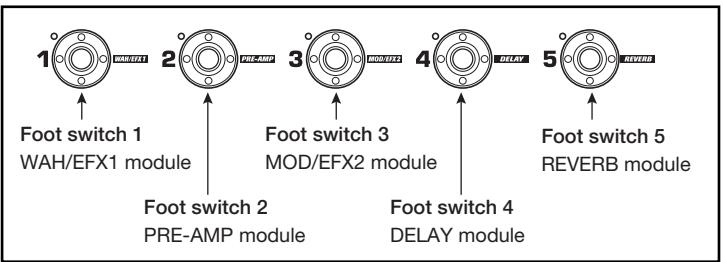
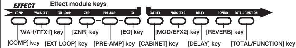
2. Press the foot switch for the module to be switched on and off.
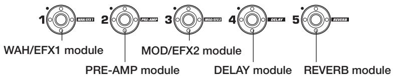
[Foot switch and corresponding modules]
- To return to play mode, press the BANK [▼] foot switch.
Quick Guide 2 (Edit Mode/Store Mode Operation)
This section explains how to edit a selected patch and how to store the changes you have made.
1 Editing a patch (edit mode)
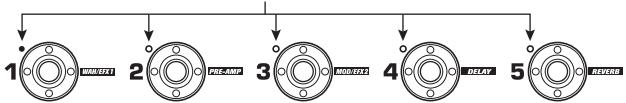
1. Press the effect module key for the module to edit.
The unit switches to edit mode. By repeatedly pressing the effect module key, the respective module can be toggled between on and off.
[Display in edit mode]
Parameter number/
Parameter name
NOTE
If you press the PRE-AMP/EQ module key, the display will be different. For details, see page 25.
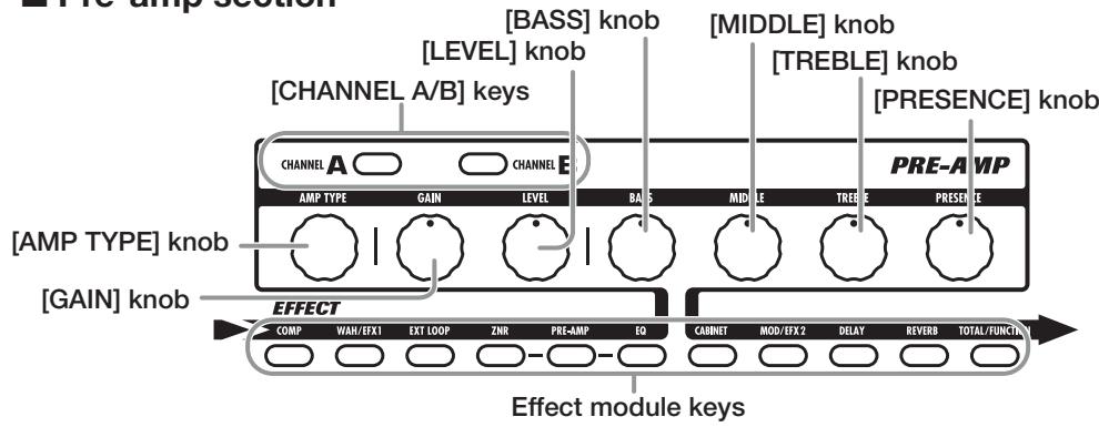
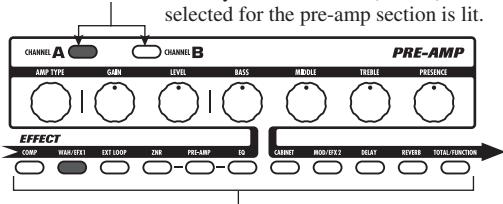
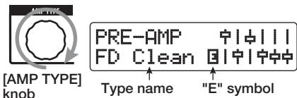
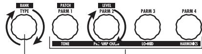
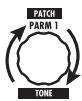
2. Use the [TYPE] knob and parameter knobs 1 - 4 to make adjustments.
[TYPE] knob
Changes the effect type.
![ZOOM G92TT - Use the [TYPE] knob and parameter knobs 1 - 4 to make adjustments. - 1](/content/2025/01/152275/images/eb7a45e0a17828126eb76676a109918495aa149c9a6495f2b874bc07a7de91fa.jpg)
![ZOOM G92TT - Use the [TYPE] knob and parameter knobs 1 - 4 to make adjustments. - 2](/content/2025/01/152275/images/61f6f2c2976a1e9a2161f954c481d3e193919b31138ea4bdbf6cb1f2d2e3003d.jpg)
Parameter knobs 1-4
Change the respective parameter.
For information on parameters assigned to the knobs, see page 60 - 75.
HINT
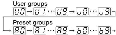
- The effect type (distortion type) of the PRE-AMP module can be changed with the [AMP TYPE] knob.
- The major parameters of the PRE-AMP/EQ module can be edited with the knobs of the pre-amp section, in the same way as in play mode.
NOTE
The changes that you have made to a patch will be lost when you select another patch. To keep the changes, store the patch first.
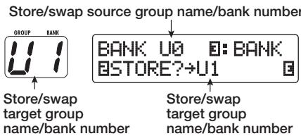
Storing a patch (store mode)
- In play mode, manual mode, or edit mode, press the [STORE/SWAP] key.
[Display in store mode]
Store target group name/bank number
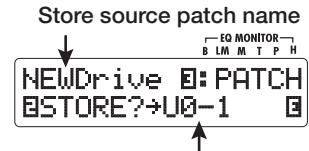
Store target group name, bank number, patch number
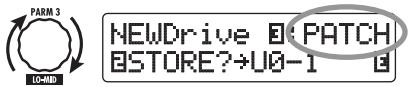
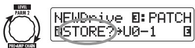
2. The indication "PATCH" appears in the top right of the display and the indication "STORE?" in the bottom left. Make sure that the operation is what you intend to do.
In this condition, you can store individual patches. If the display is different, use parameter knob 2 to bring up the "STORE?" indication and parameter knob 3 to bring up the "PATCH" indication.
HINT In store mode, you can swap patches as well as store and swap entire banks ( p. 28).
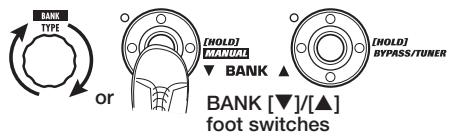
3. Use the BANK [] / [] foot switches and foot switches 1 - 5 to select the store target bank and patch number.
NOTE - Only user group patches can be specified as store target.
- When a patch from a user group is selected, this patch becomes the default store target.
- When a patch from a preset group is selected, the first user group patch becomes the default store target.
4. Press the [STORE/SWAP] key once more.
The store process is carried out, and the unit returns to play mode.
HINT You can return the user group patches easily to the factory default settings ( p. 29).
Selecting Patches for Playing (Play Mode)
Immediately after you turn on the G9.2tt, it is always in the mode for selecting and using patches (play mode). The most recently used patch is automatically called up again. The various operation steps in play mode are described in this section.
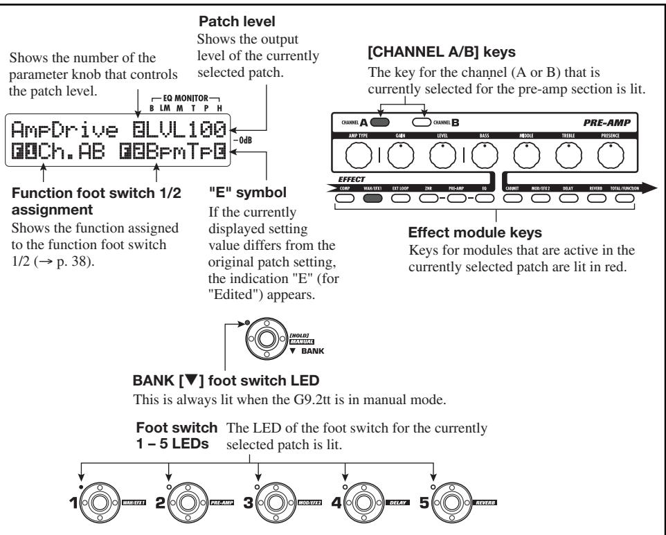
Panel display
In play mode, the following information is shown on the panel.
Group name (U, u, A, b)
Groups A and b are read-only groups (preset groups). Groups U and u are read/write enabled groups (user groups).
Shows the number of the parameter knob that adjusts the patch output level.
Patch level
Shows the output level setting (2-100) for the currently selected patch
"E" symbol
If the currently displayed setting value differs from the original patch setting, the indication "E" (for "Edited") appears.
Function foot switch 1/2 assignment
Shows the function assigned to the function foot switch 1 / 2( p.38)
[CHANNEL A/B] keys The key for the channel (A or B) that is currently
Effect module
keys
Keys for modules that are active in the currently selected patch are lit in red.
selected patch is lit.
Foot switch
1-5 LEDs
Selecting a patch
This section explains how to select a patch in play mode.
- Press a foot switch 1 - 5 whose LED is not lit.
The LED of the pressed switch lights up, indicating that a new patch has been called up.
HINT
- In play mode, you can select a patch by turning parameter knob 1.
-
When you press a foot switch whose LED is lit, the same patch is called up once more.
-
To switch to a patch in another bank, use the BANK [] / [] foot switches to change the bank and then use foot switches 1 - 5 to select the patch.
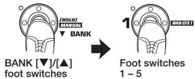
When you repeatedly press the BANK [▲] foot switch, the G9.2tt switches the group/bank as follows.
HINT
In play mode, you can switch the group/bank by turning the [TYPE] knob.
NOTE
- When using the BANK []/[] foot switches to change banks, press and release the switch quickly.
- If you keep the BANK [▼] foot switch depressed for more than one second, the G9.2tt switches to manual mode (→ p. 19).
- If you keep the BANK [▲] foot switch depressed for more than one second, the G9.2tt switches to the bypass condition (effects off). If you keep the switch depressed further, the G9.2tt switches to the mute condition (original sound and effect sound both off) ( p. 21).
Adjusting the sound
In play mode, you can use the knobs on the panel to adjust the basic parameters of the pre-amp section (distortion type and intensity, EQ boost/ cut etc.).
- In play mode, select the patch.
- Press one of the [CHANNEL A/B] keys to select the pre-amp channel A or B for which to make the adjustment.

The pre-amp section of the G9.2tt has two separate channels which allow individual settings. Simply pressing one of the [CHANNEL A/B] keys instantly switches the channel.
HINT
You can switch between channel A and B with the FUNCTION foot switch 1 / 2 ( p.38)
- To change the distortion type, turn the [AMP TYPE] knob.
The [AMP TYPE] knob selects the distortion type (the amp or compact effect that is being simulated). When you turn the knob, the name of the new amp type appears on the display.
HINT
- When you have changed the distortion type, the "E" symbol appears on the display, and the [STORE/SWAP] key lights up.
-
If the currently displayed setting value differs from the original patch setting, the indication "E" (for "Edited") appears.
-
The lit [STORE/SWAP] key indicates that one or more items (including items not currently displayed) have been changed from the contents of the original patch. If all items are returned to their original settings, the key will go out.
4. To change other major parameters in the pre-amp section, operate the respective knob (see illustration below).
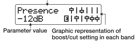
When you turn a knob, the name and the current setting of the respective parameter appear on the display. Operating the [BASS], [MIDDLE], [TREBLE], or [PRESENCE] knob will boost or cut the respective band, and the setting is reflected in the graph on the right side of the display.
Name of currently adjusted parameter
HINT
When you perform step 3 or step 4, the G9.2tt switches to edit mode. To return to play mode, press the [EXIT] key. (For details on edit mode, see page 24.)
5. To adjust the overall level of the patch, turn parameter knob 2 in play mode.

The patch level is a parameter that controls the output level of the respective patch. The setting range is 2 - 100. A setting of 80 results in unity gain (no level increase or decrease).
NOTE
The changes that you have made to a patch will be lost when you select another patch. To keep the changes, store the patch first ( p. 28).
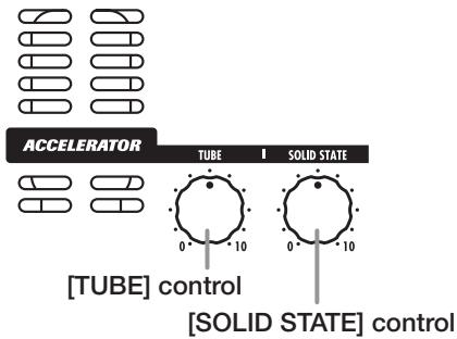
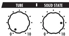
Using the Accelerator
The input stage of the G9.2tt incorporates an Accelerator function that amplifies the analog signal before effect processing using a tube or solid state circuit. This lets you mix characteristic tube compression and distortion with clean solid state sound and then send the signal to the effect circuitry.
HINT
The Accelerator is active in all modes. Accelerator settings are not stored as part of the patch.
To adjust the Accelerator, use the controls of the Accelerator section on the panel. The control functions are explained below.
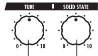
[TUBE] control
[SOLID STATE] control
- [TUBE] control
This control adjusts the input signal gain of the tube circuit. Turning the control clockwise increases gain and also increases distortion. Settings higher than about three o'clock will drastically increase the volume and distortion. This can be used to strongly emphasize the typical tube compression and distortion character.
- Clean - Tube Mix
This setting gives a mix of solid state clean sound and tube distortion sound.
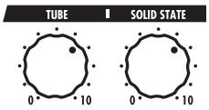
[SOLID STATE] control
This control adjusts the input signal gain of the solid state circuit. Turning the control clockwise increases only the volume. At the maximum position, gain is about +6 dB. This can be used to increase the gain for the signal before effect processing.
Depending on the settings made for the Accelerator, the effect intensity of the COMP module and the distortion depth of the PRE-AMP module also will change. When editing patches, we recommend using the following setting examples for the Accelerator.
- Normal Clean
This setting gives a clean tone with minimal distortion.
Tube Pre-amp
This setting emphasizes the tube-like compression feeling. Raising the [TUBE] control further will drastically increase the volume and distortion.
NOTE
When both controls are set to minimum, no signal will be input to the G9.2tt.
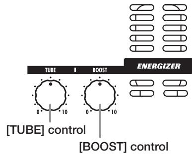
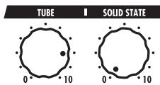
Using the Energizer
The G9.2tt incorporates an Energizer function that processes the analog output signal using a tube circuit.
This feature is suitable for making the guitar stand out in an ensemble setting, or for adding that characteristic tube distortion sound.
HINT
The Energizer is active in all modes. The Energizer settings are not stored as part of the patch.
To adjust the Energizer, use the controls of the Energizer section on the panel. The control functions are explained below.
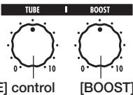
[BOOST] control
[TUBE] control
This control adds characteristic tube distortion to the sound, making the guitar stand out more distinctly. When the knob is turned fully counterclockwise, the effect is off. Turning the knob clockwise gradually increases the tube circuit gain, resulting in warmer, more solid crunch or drive sound.
Normally, you should set the control to a
position where distortion is not too audible, but you can set it higher when you purposely want to emphasize the tube distortion.
- [BOOST] control
This control boosts specific frequency bands to make the sound more pronounced. When the knob is turned fully counterclockwise, the effect is off. Turning the knob clockwise gradually boosts the low frequencies and the area around 2kHz Especially when using a small guitar amp or an audio system with flat response, this can be helpful to produce more dynamic sound.
The [BOOST] control is useful in such situations, and for bringing the sound of the guitar more to the foreground when playing in a band.
NOTE
- The intensity of the distortion achieved with the [TUBE] control depends on the guitar and type of pickup.
- When both controls are fully turned up, the volume level will be higher and excessive distortion may occur.
Switching Modules On and Off With Your Foot During Play (Manual Mode)
The condition where foot switches 1 - 5 are used to switch the major modules in a patch on and off individually is called "manual mode". In this mode, the single effects of the G9.2tt can be controlled with your foot like independent compact effects.
-
In play mode, select a patch.
-
Press and hold the BANK [▼] foot switch for at least 1 second.

The LED of the BANK [] foot switch lights up and the G9.2tt switches to manual mode. In manual mode, the following information
appears on the panel (see illustration below).
NOTE
In manual mode, you cannot use the foot switches to select patches. However, the [TYPE] knob (group/bank selection) and the parameter knob 1 (patch selection) operate in the same way as in play mode. Please note that the G9.2tt goes back to play mode when you change patches.
- To switch a module between on and off, press the foot switch for that module.
In manual mode, you can use foot switches 1 - 5 to switch the major effect modules on or off. The module/switch allocation is shown below.
HINT
- When a module is switched on/off, the [STORE/ SWAP] key lights up.
- In manual mode, you can use the knobs on the panel as in play mode to adjust pre-amp parameters, patch level, Accelerator, and Energizer. For details on operation steps, see "Adjusting the sound" in the section on play mode ( p. 15).
-
From manual mode you can switch to edit mode for editing patches. For details on edit mode, see page 24.
-
To return to play mode, press the BANK [▼] foot switch.

NOTE
The changes that you have made to a patch will be lost when you select another patch. To keep the changes, store the patch first ( p.28).
Using the Internal Tuner (Bypass/Mute Condition)
The G9.2tt incorporates a tuner function that supports regular chromatic tuning as well as special tuning. This section explains the steps for using the tuner.
Using the chromatic tuner
To use the chromatic tuner function, proceed as follows.
- In play mode, manual mode, or edit mode, press and hold the BANK [▲] foot switch.

To use the tuner, the G9.2tt must be set to the bypass condition (effects off) or mute condition (original sound and effect sound both off).
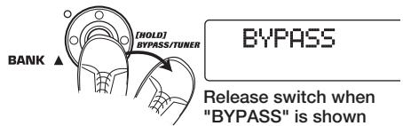
- To switch to the bypass condition
Hold the BANK [▲] foot switch for about 1 second, until the indication "BYPASS" appears on the display. Then release the foot switch. The G9.2tt is now in the bypass condition.
HINT
You can switch to the bypass condition by pressing the [BYPASS/TUNER] key.
- To switch to the mute condition
Hold the BANK [▲] foot switch until the indication "BYPASS" changes to "MUTE". Then release the foot switch. The G9.2tt is now in the mute condition.

After "BYPASS" or "MUTE" was shown, the display automatically switches to the tuning display.
NOTE
You can switch to the mute condition by pressing and holding the [BYPASS/TUNER] key.
HINT
- The built-in expression pedals function as volume pedals in the bypass condition (in the mute condition, the pedals have no effect).
- By turning the parameter knob 2, you can select other tuner types besides the chromatic tuner. For more information, see the next section.
-
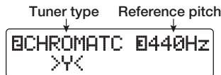
The number shown in reverse on the display indicates that the corresponding parameter knob can be used for adjustment.
-
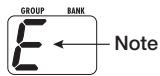
Play the open string to tune.
The [GROUP/BANK] indicator shows the note which is closest to the current pitch.
| Note | [GROUP/BANK] indicator | Note | [GROUP/BANK] indicator |
| A b | A B | D | D |
| A | A | E b | E b |
| B b | B B | E | E |
| B | B | F | F |
| C | C | G b | G b |
| D b | D B | G | D |
The > < symbols in the lower part of the display show by how much the pitch differs from the displayed note.
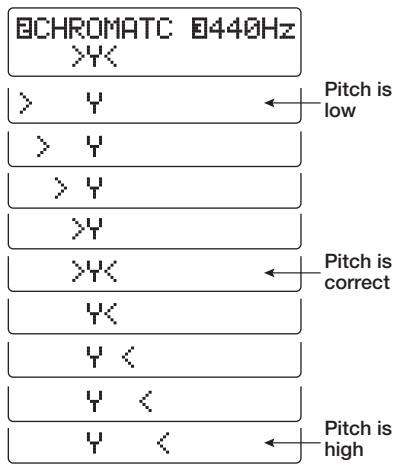
- Tune the string of your instrument while checking the note and pitch indication.
HINT
First you should perform rough tuning to bring up the desired note indication, and then watch the lower part of the display and fine tune the pitch.
- To change the reference pitch of the tuner, turn parameter knob 3.

After the G9.2tt is turned on, the tuner reference pitch is always "440 Hz (center A = 440 Hz). The adjustment range using parameter knob 3 is center A = 435 - 445 Hz, in 1-Hz steps.
BCHROMATC 442Hz YK
HINT
When the G9.2tt is turned off and on again, the reference pitch will be reset to 440Hz .
- When tuning is completed, press one of the BANK [] / [] foot switches.

The G9.2tt returns to the previous mode. If the G9.2tt was in edit mode, it will be switched to play mode.
HINT
The bypass/mute condition can be canceled by pressing the [BYPASS/TUNER] key, [EXIT] key, or one of the foot switches 1 - 5.
Using other tuner types
Besides chromatic tuning, the G9.2tt offers various other tuning types such as standard tuning for guitar and bass, open tuning, etc. To use these functions, proceed as follows.
- Switch the G9.2tt to the bypass or mute condition as described in step 1
of "Using the chromatic tuner".
The display shows the tuning indication.
- Turn parameter knob 2 to select the tuner type.
The available tuner types and the corresponding note names for each string are listed below.
If you select "OPEN A" as tuner type, the [GROUP/BANK] indicator and display indication will be as follows.
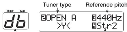
Correct note for selected string String number
- If necessary, turn parameter knob 3 to change the reference pitch of the tuner.
The setting range is center A = 435 - 445Hz , in 1-Hz steps.
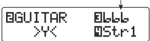
When a setting other than chromatic has been selected as tuner type, turning parameter knob 3 further anticlockwise from the "435" setting selects the setting "b" (one semitone lower), "bb" (two semitones lower), and "bbb" (three semitones lower).
Optional tuning to 1 - 3 semitones lower
HINT
When the G9.2tt is turned off and on again, the reference pitch will be reset to 440Hz .
- Play the open string of the indicated number and adjust the pitch.
- Turn parameter knob 4 to switch to other strings.
- Tune other strings in the same way.
- When tuning is completed, press one of the BANK [] / [] foot switches.
The G9.2tt returns to the previous mode. If the G9.2tt was in edit mode, it will be switched to play mode.
HINT
When the G9.2tt is turned off and on again, the tuner type setting will be reset to the default (chromatic tuner).
| Tuner type | GUITAR | BASS | OPEN A | OPEN G | OPEN E | OPEN D | DADGAD | |
| String number | STR1 | E | E | E | d | E | d | d |
| STR2 | b | d | db | b | b | R | R | |
| STR3 | L | R | R | L | Rb | Lb | L | |
| STR4 | d | E | E | d | E | d | d | |
| STR5 | R | b | R | L | b | R | R | |
| STR6 | E | E | d | E | d | d | ||
| STR7 | b | |||||||
Changing the Sound of a Patch (Edit Mode)
The condition where you can change the effect types and settings that make up a patch is called "edit mode". This section describes how to use this mode.
Patch configuration
As shown in the "Patch configuration" illustration below, the G9.2tt can be thought of as a series of several single effects (effect modules). A combination of these modules and the settings for each module are stored as a patch.
Almost all modules comprise several different effects (called effect types), one of which is selected at any given time. For example, the MOD/EFX2 module allows selection of either CHORUS, PITCH SHIFTER, DELAY, etc.
The elements that determine the sound of a patch are called effect parameters. Each effect type has its own parameters that can be controlled with knobs on the panel. Even within the same module, when the effect type is different, the effect parameters that can be controlled will also be different.
In the module configuration shown below, the series of modules EXT LOOP, ZNR, PRE-AMP, EQ, and CABINET operates as a virtual pre-amp section. Depending on the application, this section can be inserted after the WAH/EFX1 module or after the DELAY module ( p. 58). For the ZNR, PRE-AMP and EQ modules, different settings can be made in two channels (A/B).
Basic edit mode steps
The basic steps that are normally taken in edit mode are explained here. For details on effect types and parameters for each module, see the section "Effect Types and Parameters" on page 60 -75.
1. Select the patch to edit.
The patch can be from a preset group (A/b) or user group (U / u) . However, if you have edited a patch from a preset group, it can only be stored in a user group ( p.28)
2. In play mode or manual mode, press the effect module key (see illustration on next page) to select the module on which to operate.
The G9.2tt switches to edit mode, and the display changes as follows.
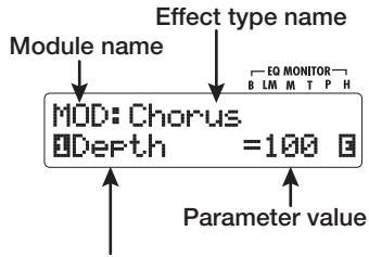
[Module other than PRE-AMP/EQ]
Module name Effect type name
![ZOOM G92TT - [Module other than PRE-AMP/EQ] - 1](/content/2025/01/152275/images/3ba09a9b8e19b98ac01673be0f586ef783866feb7547f5bfb30ee92a4d981fa9.jpg)
Parameter number
Currently selected parameter and its setting value
HINT
The effect module keys for modules that are ON in the currently selected patch are lit in red (keys for modules that are OFF are not lit). When you press
[Patch configuration]
a key to select a module, the key color changes to orange (or to green if the module is off).
other item has been changed, the [STORE/ SWAP] key remains lit.
[PRE-AMP module]
![ZOOM G92TT - [PRE-AMP module] - 1](/content/2025/01/152275/images/94160038d497f5cff3682e80f22eb58fbf4473dbc18dd729e50932989db59812.jpg)
[EQ module]
![ZOOM G92TT - [EQ module] - 1](/content/2025/01/152275/images/14ea1dccdd467b32ea002d8bde63fe1a2a46d1a759430f9f33c43ab0af9964df.jpg)
NOTE
- If edit mode was activated from play mode, foot switches 1 - 5 can be used to switch patches. However, note that editing changes will be lost when switching patches during editing.
- When edit mode was activated from manual mode, the foot switches 1 - 5 can be used to switch a specific module on or off.
3. To switch the selected module between on and off, press the same module key once more.
When the module is off, the indication "Module Off" is shown on the display. Pressing the same key once more in this condition switches the module on.
HINT
- If any module on/off status, effect type selection, or a parameter setting value has been changed at least once, the [STORE/SWAP] key lights up and the indication "E" appears next to the item.
- The "E" indication disappears when the item is returned to the original value. However, if any
NOTE
The PRE-AMP, ZNR, and EQ modules can be set to on or off separately for each channel (A/B).
4. To edit the selected module, proceed as follows.
- When a module other than PRE-AMP/ EQ is selected
Switch the effect type as needed with the [TYPE] knob (for modules having several effect types), and use the parameter knobs 1-4 to adjust the parameters of the effect type. Which parameters are assigned to the parameter knobs 1-4 differs, depending on the module and effect type ( p.60-75).
[TYPE] knob Parameter knobs 1 - 4
When you turn a parameter knob, the display changes as follows.
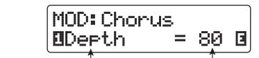
Number of operated parameter knob and parameter name
Parameter value
HINT
For effect modules with only one effect type (EQ module, CABINET module etc.), the effect type cannot be changed.
- When PRE-AMP/EQ module is selected
The PRE-AMP and EQ module parameters can always be adjusted with the knobs and keys of the pre-amp section, regardless of which module is currently selected. The functions of the knobs and keys are listed in Figure 1 below.
When the effect module key [PRE-AMP]/[EQ] is selected, parameter knobs 1 - 4 can be used to adjust other parameters of the PRE-AMP/EQ module. The functions of the knobs are listed in Figure 2 below.
HINT
- When the PRE-AMP parameter of the pre-amp section is adjusted, the PRE-AMP module is automatically selected. When an EQ parameter
is adjusted, the EQ module is automatically selected.
- The PRE-AMP, ZNR, and EQ modules allow separate parameter settings for the two channels (A/B). Select the channel first, and then adjust the parameter.
- Repeat steps 2 - 4 to edit other modules in the same way.
- When editing is finished, press the [EXIT] key.

The G9.2tt returns to the previous mode.
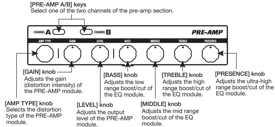
Figure 1 [Editing PRE-AMP/EQ module with pre-amp section]
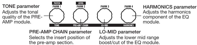
Figure 2 [Editing PRE-AMP/EQ module with parameter knobs 1 - 4]
NOTE
- The changes that you have made to a patch will be lost when you select another patch. To keep the changes, store the patch first ( p.28) .
- The patch level (output level of individual patch) cannot be changed in edit mode. Use play mode or manual mode to set the level.
HINT
If edit mode was entered from play mode, you can return to play mode by pressing the BANK [] / [] foot switches or foot switches 1 - 5. In this case, the bank/patch will be switched at the same time.
Changing a patch name
You can change the name of an edited patch. To do this, proceed as follows.
- In play mode, manual mode, or edit mode, press the [TOTAL/FUNCTION] effect module key.

- Turn the [TYPE] knob to bring up the patch name on the lower part of the display.
The first character of the patch name is shown alternating with a black square.
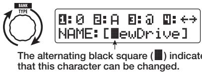
- Turn parameter knob 4 to move the character input position, and use parameter knobs 1 - 3 to select the new character.
Parameter knobs 1 - 3 select characters as follows.
Parameter knob 1 (numerals): 0 - 9
Parameter knob 2 (letters): A-Z, a-z
Parameter knob 3 (symbols):(space)
$$ ! ^ {\prime \prime} # \$ \% \& ^ {\prime} () * +, -, /; < > = ? @ [ ] ^ {\wedge} _ {^ {\prime}} {} $$
- Repeat step 3 until the patch name is as desired. Then press the [EXIT] key.
Storing Patches and Banks (Store Mode)
This section explains how to use the store mode. In store mode, you can store edited patches in memory, or swap the store location of user group patches. Storing and swapping can also be carried out for entire banks. The patches of the user groups can be returned to the factory default condition at any time.
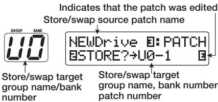
Storing/swapping patches
This section explains how to store and swap patches.
- In play mode, manual mode, or edit mode, press the [STORE/SWAP] key.

The G9.2tt switches to the store standby condition, and the currently selected patch becomes the store/swap source.
The [GROUP/BANK] indicator shows the store/ swap target group name and bank number.
HINT
- In the factory default condition, the user groups (U, u) contain the same patches as the preset groups (A, b).
- If a patch has been edited, it will be stored or swapped in the edited condition.
-
If a patch from a preset group was selected when you pressed the [STORE/SWAP] key, the first user group patch will automatically be selected as store target.
-
To store/swap individual patches, turn parameter knob 3 to bring up the
indication "PATCH" in the top right of the display.
NOTE
When "BANK" is shown, the subsequent operation will be carried out for the entire bank. Make sure that the correct indication is shown.
- Turn parameter knob 2 to bring up the indication "STORE?" or "SWAP?" on the display.
When "STORE?" is selected, the current patch can be stored as any user patch.
When "SWAP?" is selected, the current user patch can be swapped with any other user patch.
NOTE
If the source patch is from a preset group, the indication "SWAP?" does not appear.
- Use the [TYPE] knob or BANK [▼]/[▲] foot switches to select the store/ swap target group name/bank number.
- Use parameter knob 1 or the foot switches 1 - 5 to select the store/ swap target patch number.
- Press the [STORE/SWAP] key once more.
The store/swap process is carried out, and the G9.2tt then returns to the play mode with the store/swap target patch being selected.
By pressing the [EXIT] key instead of the [STORE/SWAP] key, you can cancel the process and return to the previous mode.
NOTE
The Energizer and Accelerator settings are not stored as part of the patch.
Storing/swapping banks
This section explains how to store and swap entire banks.
- In play mode, manual mode, or edit mode, press the [STORE/SWAP] key.
The G9.2tt switches to the store standby condition, and the currently selected bank becomes the store/swap source. - To store/swap entire banks, turn parameter knob 3 to bring up the indication "BANK" in the top right of the display.
- Turn parameter knob 2 to bring up the indication "STORE?" or "SWAP?" on the display.
When "STORE?" is selected, the current bank can be stored as any user bank.
When "SWAP?" is selected, the current user bank can be swapped with any other user bank.
NOTE
If the source bank is from a preset group, the indication "SWAP?" does not appear.
- Use the [TYPE] knob or BANK [▼]/[▲] foot switches to select the store/swap target bank.
- Press the [STORE/SWAP] key once more.
The store/swap process is carried out, and the G9.2tt then returns to play mode with the store/ swap target bank being selected.
By pressing the [EXIT] key instead of the [STORE/SWAP] key, you can cancel the process and return to the previous mode.
Returning patches to factory default condition
Even if you have made changes to the user group patches, you can return all patches to the factory default condition at any time (All Initialize).
NOTE
When you perform the All Initialize function, all patches stored in the user area will be overwritten. Proceed with care.
1. Turn power to the G9.2tt on while holding down the [STORE/SWAP] key.
![ZOOM G92TT - Turn power to the G9.2tt on while holding down the [STORE/SWAP] key. - 1](/content/2025/01/152275/images/d5a076e543a7639f6bb4799f3d1c967d736daae2491061da8be6575ce4aa7be4.jpg)
The indication "All Initialize?" appears on the display.
All Initialize?
Y:STORE N:EXIT
2. Press the [STORE/SWAP] key once more.
All patches are returned to the factory default condition, and the G9.2tt switches to play mode. By pressing the [EXIT] key before performing step 2, you can cancel the process.
Using the Expression Pedals
This section explains how to use the two built-in expression pedals of the G9.2tt.
About the expression. pedals
The G9.2tt comes standard with two expression pedals that can be used to control specific effect parameters in real time.
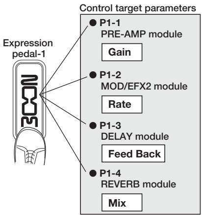
Expression pedal 1 on the left side has four control targets (P1-1 to P1-4), and a parameter can be assigned for each control target. This makes it possible to adjust up to four parameters of different modules simultaneously. A setting example is shown below, to give you an idea of how the pedal can be used.
PRE-AMP module when moved in the vertical direction and the Rate parameter of the MOD/ EFX2 module when moved in the horizontal direction. It is also possible to control both at the same time with one pedal.
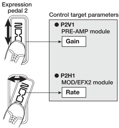
Expression pedal 2 on the right side the Z-Pedal that senses not only vertical but also horizontal movement. It has four control targets in the vertical direction (P2V1 to P2V4) and four control targets in the horizontal direction (P2H1 to P2H4). A parameter can be assigned for each control target.
With a setting such as shown in the example at right, the pedal adjusts the Gain parameter of the
HINT
- The parameter adjustment range covered by expression pedals 1 and 2 can be set for each control target separately.
- In bypass mode, both expression pedals function as a volume pedal when moved in the vertical direction. (Moving expression pedal 2 in the horizontal direction has no effect.)
- In mute mode, both expression pedals have no effect.
NOTE
Expression pedal 2 of the G9.2tt is designed for operation with one foot. When the pedal is fully turned to the right, pushing it strongly down, hitting it, or otherwise exerting strong force on it will damage the pedal. Be sure to operate the pedal only within its designated range.
Assigning control targets to expression pedal 1
This section describes how to assign a control target to expression pedal 1.
- In play mode, select the patch.
HINT
The parameters to be controlled by expression.
pedals 1/2 and the setting range can be set separately for each patch.
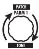
2. Press the [PEDAL 1 SETTING] key.
The display changes as follows.
![ZOOM G92TT - Press the [PEDAL 1 SETTING] key. - 1](/content/2025/01/152275/images/41477907bf037c2c64b08ff0c2f602707694ef6c3cc65089b8b4e6eba3923547.jpg)
HINT
The expression pedal 1/2 setting is included in the TOTAL/FUNCTION module for the respective patch. The above display can also be called up by pressing the [TOTAL/FUNCTION] effect module key and turning the [TYPE] knob.
- Turn the [TYPE] knob to select one of the four control targets (P1-1 to P1-4).

The operation steps for setting the control targets P1-1 to P1-4 are the same.
- Turn parameter knob 1 to select the parameter that is to be controlled.
As you turn parameter knob 1, the effect parameter and effect module changes.
HINT
- For information on which parameters can be selected as control targets, see "Effect Types and Parameters" on pages 60 - 75.
- When "Volume" is selected as control target, expression pedal 1 functions as a volume pedal.
- When "NOT Assign" is displayed, no parameter is assigned to the current control target. By setting all four control targets to "NOT Assign", expression pedal 1 can be defeated.
NOTE
If you select "NOT Assign", steps 5 and 6 cannot be carried out.
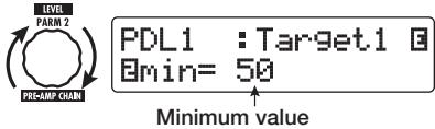
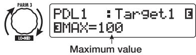
- To set the adjustment range for the parameter to be controlled, use parameter knob 2 (minimum value) and parameter knob 3 (maximum value).
The settings selected with parameter knobs 2 and 3 determine the value when the pedal is fully raised (minimum value) and fully depressed (maximum value).
The display changes as follows.
When parameter knob 2 is operated
When parameter knob 3 is operated
HINT
- The available range setting depends on the parameter selected in step 4.
- It is also possible to set "min" to a higher value than "MAX". In that case, the parameter value will be minimum when the pedal is fully depressed and maximum when the pedal is fully raised.
6. To use expression pedal 1 for switching the module on and off, turn parameter knob 4 and select "Enable".
Expression pedal 1 has a switch that is triggered when the pedal is pushed a bit further, after the fully down position is reached. The module to which the selected parameter belongs will be switched on or off.
When you turn parameter knob 4, the display changes as follows.

PDL1 :Target1
Switch:Enable
HINT
If you select "Disable" at the above display, module on/off switching is not available.
- Repeat steps 3 - 6 to set the other control targets in the same way.
NOTE
It is also possible to specify the same parameter for more than one control target, but in some cases, extreme parameter value changes may lead to noise. This is not a defect.
- When all settings for expression pedal 1 have been made, press the [EXIT] key.

The unit returns to play mode.
- If required, store the patch.
NOTE
Any changes in pedal settings will be lost when you select a new patch. Be sure to store the patch if you want to keep the changes ( p. 28).
Assigning control targets to expression pedal 2
This section describes how to assign a control target to expression pedal 2. For the vertical direction and the horizontal direction, four control targets each can be assigned. Module on/off switching is available for the vertical direction only.
- In play mode, select the patch.
2. Press the [PEDAL 2 SETTING] key.
The display changes as follows.
![ZOOM G92TT - Press the [PEDAL 2 SETTING] key. - 1](/content/2025/01/152275/images/a65ee77c8185012e5b3130cec0ffa123cda81878ec6c1eb99d23ab9d13f0ab93.jpg)
HINT
The expression pedal 1/2 setting is included in the TOTAL/FUNCTION module for the respective patch. The above display can also be called up by pressing the [TOTAL/FUNCTION] effect module key and turning the [TYPE] knob.
- To assign a control target for the vertical direction, turn the [TYPE] knob to select one of the four vertical direction control targets (P2V1 to P2V4).

The operation steps for setting the vertical direction control targets P2V1 to P2V4 are the same.
4. Turn parameter knob 1 to select the parameter that is to be controlled.

As you turn parameter knob 1, the effect parameter and effect module settings change.
HINT
- For information on which parameters can be selected as control targets, see "Effect Types and Parameters" on pages 60 - 75.
- When "Volume" is selected as control target, expression pedal 2 functions as a volume pedal.
- When "NOT Assign" is displayed, no parameter is assigned to the current control target. By setting all four control targets to "NOT Assign", the vertical direction action of expression pedal 2 can be defeated.
NOTE
If you select "NOT Assign", steps 5 and 6 cannot be carried out.
5. To set the adjustment range for the parameter to be controlled, use parameter knob 2 (minimum value) and parameter knob 3 (maximum value).
The display changes as follows.
When parameter knob 2 is operated

PDL2-U:Target1 B
Bmin=50
↑
Minimum value
■ When parameter knob 3 is operated

PDL2-U:Target1 E MAX=100 Maximum value
HINT
- The available range setting depends on the parameter selected in step 4.
- It is also possible to set "min" to a higher value than "MAX". In that case, the parameter value will be minimum when the pedal is fully depressed and maximum when the pedal is fully raised.
6. To use expression pedal 2 for switching the module on and off, turn parameter knob 4 and select "Enable".
Expression pedal 2 has a switch that is triggered when the pedal is pushed a bit further in the vertical direction, after the fully down position is reached. The module to which the selected parameter belongs will be switched on or off.
When you turn parameter knob 4, the display changes as follows.

PDL2-U:Target1
Switch:Enable
HINT
If you select "Disable" at the above display, module on/off switching is not available.
7. Repeat steps 3 - 6 to set the other control targets for the vertical direction in the same way.
8. To assign control targets for the horizontal direction, turn the [TYPE] knob to select one of the four horizontal direction control targets (P2H1 to P2H4).
The display changes as follows.
Control target indication
Control target parameter name
![ZOOM G92TT - To assign control targets for the horizontal direction, turn the [TYPE] knob to select one of the four horizontal direction control targets (P2H1 to P2H4). - 1](/content/2025/01/152275/images/956174e327d68ac11e8c3a07eef78be1cba08d9596587c06c5a79bb72635a8cc.jpg)
P2H1=Resonance wAH:Autowah
Module name
Effect type name
The operation steps for setting the horizontal direction control targets P2H1 to P2H4 are the same.
9. Repeat steps 4 - 5 to set the parameter and minimum and maximum values for the control target.
NOTE
In the horizontal direction of expression pedal 2, no module on/off switching is possible. Therefore parameter knob 4 has no effect.
10. Repeat steps 8 - 9 to set the other control targets for the horizontal direction in the same way.
NOTE
It is also possible to specify the same parameter for more than one control target, but in some cases, extreme parameter value changes may lead to noise. This is not a defect.
11. When all settings for expression pedal 2 have been made, press the [EXIT] key.
![ZOOM G92TT - When all settings for expression pedal 2 have been made, press the [EXIT] key. - 1](/content/2025/01/152275/images/3561944718f7b8ff8318cd9cde26ce11f9426a7d9dd2587d23094b93177be94d.jpg)
The unit returns to play mode.
12. If required, store the patch.
NOTE
Any changes in pedal settings will be lost when you select a new patch. Be sure to store the patch if you want to keep the changes ( p. 28).
HINT
Expression pedal 2 incorporates a stopper for movement in the horizontal direction. If horizontal action is not required, using the stopper may be preferable.
Adjusting the expression. pedals
Expression pedals 1/2 of the G9.2tt are adjusted for optimum operation at the factory, but sometimes, readjustment may be necessary. If the action of a pedal seems to be insufficient, or if a large change occurs even if the pedal is only lightly moved, adjust the pedal as follows.
Adjusting expression pedal 1
1. Hold down the [PEDAL 1 SETTING] key while turning on power to the unit.
The display indication changes as follows.
![ZOOM G92TT - Hold down the [PEDAL 1 SETTING] key while turning on power to the unit. - 1](/content/2025/01/152275/images/6d0640879cb06a01cc490b1e53ffed7a48aa738b5574d7c6bda0ccf1926e53c6.jpg)
PDL Calibration PEDAL1...min
2. With expression pedal 1 fully raised, press the [STORE/SWAP] key.
![ZOOM G92TT - With expression pedal 1 fully raised, press the [STORE/SWAP] key. - 1](/content/2025/01/152275/images/a886553decffd728b4e132c5423e7cda20acb80eeabaa1c9cfed0472ceac63ed.jpg)
Pedal fully raised
The display indication changes as follows.
STORE/SWAP
![ZOOM G92TT - With expression pedal 1 fully raised, press the [STORE/SWAP] key. - 2](/content/2025/01/152275/images/c5e9411a0ea343e7b4175a69b1d6946050b56b3f8148d9e585c6af084ea789e9.jpg)
PDL Calibration
PEDAL1...MAX
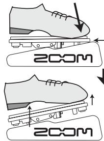
- Push expression pedal 1 fully down and then lift your foot off the pedal.
![ZOOM G92TT - With expression pedal 1 fully raised, press the [STORE/SWAP] key. - 3](/content/2025/01/152275/images/22cc6579cbbbf3ed3d4c3d6cc9ba7b6554924c61d259bb4566030abf1d37af26.jpg)
Push strongly,
so that pedal touches here
![ZOOM G92TT - With expression pedal 1 fully raised, press the [STORE/SWAP] key. - 4](/content/2025/01/152275/images/c4366cbc7aeed6e982bae76246b5ed8ffa7702ac08251a7588e6f788df1cad06.jpg)
When foot is lifted, pedal returns slightly
- Press the [STORE/SWAP] key.
STORE/SWAP
![ZOOM G92TT - With expression pedal 1 fully raised, press the [STORE/SWAP] key. - 5](/content/2025/01/152275/images/fec78139ed9d85fd7320ee41011d4fabd02700f62519ae31bbf18d16dc1d0d39.jpg)
The adjustment is completed, and the unit returns to the play mode.
HINT
- The module on/off switching point of expression pedal 1 is not affected by the pedal position in step 3. This position is always the same.
- For information about the module on/off switching function, see page 33.
- If the indication "ERROR" appears, return to step 2 and repeat the procedure.
Adjusting expression pedal 2
- Hold down the [PEDAL 2 SETTING] key while turning on power to the unit.
The display indication changes as follows.
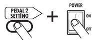
PDL Calibration
PEDAL2-U..min
- With expression pedal 2 fully raised, press the [STORE/SWAP] key.
Pedal fully raised
The display indication changes as follows.

PDL Calibration
PEDAL2-U...MAX
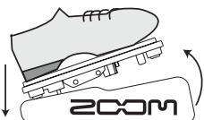
- Push expression pedal 2 fully down in the vertical direction and then lift your foot off the pedal and press the [STORE/SWAP] key.
Push strongly,
s so that pedal touches here


When foot is lifted,
pedal returns slightly
The display indication changes as follows.

PDL Calibration
PEDAL2-H..min
- Lift the stopper of expression pedal 2 to secure the pedal. Then turn the pedal fully to the right and press the [STORE/SWAP] key.
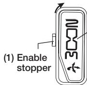
(2) Turn pedal
fully to the right
(1) Enable stopper
Session pedal 2
When you press the [STORE/SWAP] key, the display indication changes as follows.

PDL Calibration
PEDAL2-H...MAX
- Push the stopper of expression pedal 2 down, turn the pedal fully to the right, and press the [STORE/SWAP] key.
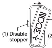
(2) Turn pedal fully.
Expression pedal 2
When you press the [STORE/SWAP] key, the adjustment is completed, and the unit returns to the play mode.
HINT
If the indication "ERROR" appears, return to step 2 and repeat the procedure.
Using the Function Foot Switches
The G9.2tt provides two programmable function foot switches on the top panel. For each switch, you can select a function from a range of options, assign it to the switch, and store the setting for each patch individually.
This section describes how to assign functions to function foot switches 1/2 .
- In play mode, select the patch.
HINT
The function foot switch 1/2 assignment can be set separately for each patch.
2. Press the [TOTAL/FUNCTION] effect module key.
The function foot switch assignment is part of the [TOTAL/FUNCTION] module.
The display changes as follows.
TOTAL/FUNCTION

TOTAL:Tempo BEPM=120
3. Turn parameter knobs 2/3 to select the function to be assigned to function foot switches 1/2.
Parameter knob 2 is used for function foot switch 1 and parameter knob 3 for function foot switch 2. The display changes as follows.
When parameter knob 2 is turned

TOTAL:Function1 BPRE-AMP CH A/BB
Function assigned to function foot switch 1
When parameter knob 3 is turned

TOTAL:Function2 EBPM TAP
Function assigned to function foot switch 2
The following functions can be assigned to function foot switches 1/2 .
PRE-AMP CH A/B
The function foot switch toggles between preamp channels A and B.
BPM TAP
The function foot switch can be used to specify the individual tempo for a patch ( p.39). When the switch is pressed repeatedly, the interval between the last two presses is detected automatically and taken as the new tempo setting.
HINT
Using the tempo set here, specific parameters (Time and Rate) can be synchronized in note units ( .40) .
Delay TAP
The function foot switch can be used to specify the Time parameter for the DELAY module.
HINT
- While BPM TAP specifies the tempo for an individual patch, Delay TAP uses the foot switch operation interval to directly set the Time parameter value (delay time).
- To use Delay TAP, the DELAY module must be active for that patch.
Hold Delay
The function foot switch toggles hold delay between on and off. When you press the function foot switch in a patch for which hold delay is active, the hold function is turned on and the current delay sound is repeated. Pressing the function foot switch once more cancels hold, and the delay sound will decay naturally (see illustration on next page).


HINT
To use Hold Delay, the DELAY module must be active for that patch.
Delay Mute
The function foot switch toggles DELAY module input muting between on and off.
- Bypass Off, Mute OnOff
The function foot switch toggles the bypass mode or mute mode between on and off. When either mode is activated, the tuner display comes up.
- Manual Mode
The function foot switch toggles between play mode and manual mode.
COMP OnOff, WAH/EFX1 OnOff, EXT LOOP OnOff, ZNR OnOff, PRE-AMP OnOff, EQ OnOff, MOD/EFX2 OnOff, DELAY OnOff, REVERB OnOff
The function foot switch toggles the respective module between on and off.
HINT
- When you select "PRE-AMP CH A/B", the LED of the respective function foot switch lights up in red (A) or green (B). When you select "BPM TAP" or "Delay TAP", the LED flashes orange in sync with the BPM setting.
- It is also possible to assign the same function to both function foot switches.
4. After selecting a function to assign to the function foot switch, press the [EXIT] key.
NOTE
Any changes in assignment settings will be lost when you select a new patch. Be sure to store the patch if you want to keep the changes ( p. 28).
When you next call up the stored patch, the function foot switch will control the selected function.
Specifying the tempo for a patch
The G9.2tt lets you specify a tempo for each individual patch and synchronize specific parameters to this tempo in note units. This section explains how to specify and use the tempo setting for a patch.
- In play mode, select the patch.
2. Press the [TOTAL/FUNCTION] effect module key.
The tempo setting for each patch is part of the [TOTAL/FUNCTION] module.
When you press the [TOTAL/FUNCTION] effect module key, the current tempo setting appears on the display.
TOTAL/FUNCTION

TOTAL: TemFO
BPM=120
3. Turn parameter knob 1 to set the tempo.
The tempo setting range is 40 - 250.
4. To synchronize a parameter to the specified tempo, select the effect type and effect parameter to synchronize, and select the note symbol as the setting value for the parameter.
The setting value for effect parameters which support tempo synchronization can be selected in note units, using the patch specific tempo as a reference.
For example, the Time parameter of the effect type TAPE ECHO in the MOD/EFX2 module supports patch specific tempo synchronization. To use this capability, turn the respective parameter knob from the maximum setting (2000) further clockwise until a note symbol appears on the display.
HINT
In the section "Effect Types and Parameters" ( pages 60 - 75), parameters which support tempo synchronization are indicated by a note symbol.
5. Select a parameter value by selecting a note symbol.
The following note settings for parameters which support tempo synchronization are available.
| # | Thirty-second note |
| # | Sixteenth note |
| # | Quarter triplet note |
| # | Dotted sixteenth note |
| # | Eighth note |
| # | Half triplet note |
| # | Dotted eighth note |
| # | Quarter note |
| # | Dotted quarter note |
| #x2 | Quarter note x 2 |
| : | : |
| #x20 | Quarter note x 20 |
NOTE
The actual available setting range depends on the parameter.
When you have selected the eighth note setting, the Time parameter will be set to a value that corresponds to an eighth note in the patch specific tempo. When the tempo is changed, the delay time also changes accordingly.
NOTE
Depending on the combination of tempo setting and selected note symbol, the maximum value of the parameter setting range (such as 2000 ms) may be exceeded. In such a case, the value is automatically halved (or set to 1/4 if the range is still exceeded).
6. When the tempo and parameter setting is complete, press the [EXIT] key.
The unit returns to play mode. Store the patch as necessary.
The above procedure uses the tempo set in step 3 as reference for the note setting made in step 5. If the "BPM TAP" function is assigned to function foot switch 1/2 , you can specify the tempo with your foot during a performance and have the parameter change accordingly.
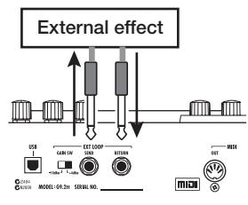
Using the Effect Loop
The EXT LOOP SEND/RETURN jacks on the rear panel of the G9.2tt allow connection of a compact effect, rack-mount effect or similar. Settings for external effect on/off and send/return level can be stored as part of a patch. This section explains how to use the effect loop.
1. Connect the external effect to the EXT LOOP SEND/RETURN jacks.

EXTLOOP
SendLevel = 50
NOTE
When "EXT LOOP Module OFF" is shown, the EXT LOOP module is currently turned off. Press the [EXT LOOP] key to turn the module on.
4. Use parameter knob 1 to adjust the level of the signal sent from the G9.2tt to the external effect (send level).
EXTLOOP
SendLevel 80
HINT
When connecting to an effect that has a rated input level of +4 dBm (rack-mount effect or similar), set the EXT LOOP GAIN switch to the "+"dBm" setting. When connecting to an instrument effect or a compact effect, use the "-10 dBm" setting.
NOTE
- The external effect should always be set to ON, to allow effect on/off switching at the G9.2tt.
- If the external effect allows adjustment of mixing ratio between original sound and effect sound (such as a reverb or delay), set the original sound to 0% and the effect sound to 100% .
2. Select the patch in play mode.
HINT
Effect loop settings can be made individually for each patch.
3. Press the [EXT LOOP] effect module key to activate edit mode.
Effect loop settings are made in the EXT LOOP module.
The display changes as follows.
HINT
If the input level at the external effect is not sufficient even with the send level turned up, or if distortion occurs at the external effect input even with the send level turned down, check whether the EXT LOOP GAIN switch setting is appropriate.
5. Use parameter knob 2 to adjust the level of the signal sent from the external effect to the G9.2tt (return level).

EXT LOOP BRet Level = 80
6. Use parameter knob 3 to adjust the level balance between the signal returned from the external effect and the internal signal of the G9.2tt (dry level).

EXT LOOP
Dry Level=80
HINT
- If the external effect is the type that mixes effect sound to the original sound (such as a reverb, delay, or chorus), adjust the level balance between original sound and effect sound by adjusting the return level and dry level.
- If the external effect is the type that processes the input signal for output (such as a compressor or EQ unit), the dry level should normally be set to 0 and the signal level should be adjusted with the return level parameter.
7. When the effect loop settings have been made, press the [EXIT] key.
![ZOOM G92TT - When the effect loop settings have been made, press the [EXIT] key. - 1](/content/2025/01/152275/images/00423140debc3c005573731d8cc84548977e595195a438b09d0204b1949b1e8b.jpg)
The unit returns to play mode.
8. Store the patch as necessary.
When you next call up the stored patch, the external effect settings will also become effective again.
HINT
If the external effect supports MIDI based program switching, the G9.2tt can control the effect by sending program change messages. In this way, patch switching at the G9.2tt and program switching at the G9.2tt can be synchronized ( p. 44).
MIDI Usage Examples
This section describes the various MIDI functions of the G9.2tt.
What you can do with MIDI
The G9.2tt lets you use MIDI in various ways, as described below.
- Send and receive patch switching information via MIDI
When you switch patches at the G9.2tt, the MIDI OUT connector carries the corresponding MIDI messages (program change, or bank select + program change). Similarly, when a valid MIDI message is received at the MIDI IN connector, the G9.2tt will perform the corresponding patch switch action.
This makes it possible to have patches at the G9.2tt switched automatically under control of a MIDI sequencer, or link operation of the G9.2tt to patch switching at other MIDI enabled effects.
- Send and receive pedal/switch/key operation information via MIDI
When you operate specific keys and foot switches of the G9.2tt, or operate the expression pedals 1/2 , the MIDI OUT connector carries the corresponding MIDI messages (control change). Similarly, when a valid MIDI message is received at the MIDI IN connector, the G9.2tt will vary the corresponding parameter.
This makes it possible to use the G9.2tt as a real-time controller for other MIDI enabled devices, or alter effect parameters and module on/off status under control of a MIDI sequencer, synthesizer, or other MIDI enabled device.
Exchange patch data between two G9.2tt units via MIDI
The patch data of the G9.2tt can be output as MIDI messages (system exclusive), for copying to another G9.2tt.
Selecting the MIDI channel
To enable correct sending and receiving of program change, control change and other MIDI messages, the MIDI channel (1 - 16) setting of the G9.2tt and the other MIDI device must be matched. To set the MIDI channel of the G9.2tt, proceed as follows.
1. In play mode, press the [AMP SELECT/System] key.
The AMP SELECT/System menu for parameters that apply to all patches appears.
![ZOOM G92TT - In play mode, press the [AMP SELECT/System] key. - 1](/content/2025/01/152275/images/dc970d9594b68fd46c109a5372e6b8fddc24da87ff70aa4efb37c249426a738a.jpg)
AMP Select 1/28 FRONT
2. Turn the [TYPE] knob to select the "MIDI Rx Ch" (MIDI receive channel) parameter.
![ZOOM G92TT - Turn the [TYPE] knob to select the "MIDI Rx Ch" (MIDI receive channel) parameter. - 1](/content/2025/01/152275/images/5feadd1afff3f6abdb9b8961574f6e5410da5b6cefbe597af3235753138e79ac.jpg)
MIDI 4/28 Rx Ch=1
3. Turn parameter knob 1 to select the MIDI channel (1 - 16) on which the G9.2tt will receive MIDI messages.

MIDI 4/28 RCh=3
4. Turn the [TYPE] knob to select the "MIDI Tx Ch" (MIDI transmit channel) parameter.
![ZOOM G92TT - Turn the [TYPE] knob to select the "MIDI Tx Ch" (MIDI transmit channel) parameter. - 1](/content/2025/01/152275/images/5b2a7419f9a72d8ab4742c72acb6d80e688bf8176a57aab3a48428e201974bc0.jpg)
MIDI 5/28
DTx Ch=1
- Turn parameter knob 1 to select the MIDI channel (1 - 16) on which the G9.2tt will send MIDI messages.
- When the setting is complete, press the [EXIT] key to exit the AMP SELECT/System menu.
The indication "Store...?" appears on the display, to allow you to store the changes.
![ZOOM G92TT - Turn the [TYPE] knob to select the "MIDI Tx Ch" (MIDI transmit channel) parameter. - 2](/content/2025/01/152275/images/2ea5f1ee7c23a74cf59fd3ae8967f215f549a453ce8c9d4cfbf5c2c371af15b1.jpg)
Store...? Y[STORE] N[EXIT]
- Press the [STORE/SWAP] key to save the changes.
![ZOOM G92TT - Turn the [TYPE] knob to select the "MIDI Tx Ch" (MIDI transmit channel) parameter. - 3](/content/2025/01/152275/images/d3774a597f03d3c597a52eb1a953c785e5ba0e2d86d0febae74f7db6a030a31b.jpg)
![ZOOM G92TT - Turn the [TYPE] knob to select the "MIDI Tx Ch" (MIDI transmit channel) parameter. - 4](/content/2025/01/152275/images/331c8830059ea1f90a76f28cecc35568fa4bf00b8c5d32ad8a127ea089abf3cb.jpg)
The MIDI channel setting is accepted, and the unit returns to play mode.
In the above condition, only the [STORE/SWAP] and [EXIT] keys are active. By pressing the [EXIT] key, you can abort the changes and return to play mode without saving.
Sending and receiving patch switching information via MIDI (program change)
You can send and receive patch changing information of the G9.2tt via MIDI as program change or bank select + program change messages.
There are two ways (program change modes) for doing this, as described below.
- Direct mode
With this method, you use a combination of MIDI bank select and program change messages to specify the patch. In the factory default condition, all patches of the G9.2tt are assigned a MIDI bank number and MIDI program change number. These can be used to directly specify each patch.
HINT
- Bank select is a MIDI message type for specifying the sound category of a synthesizer or similar. It is used in combination with program change messages.
-
Normally, bank select is specified in two parts, using the MSB (most significant bit) and LSB (least significant bit) value.
-
Mapping mode
With this method, you use only the MIDI program change messages to specify the patch. A program change map is used to assign program change numbers 0 - 127 to patches, and patches are then selected using the mapping information. With this method, a maximum of 128 patches can be specified.
■ Enable program change send/ receive
The procedure for enabling send/receive of program change (+ bank select) messages is described below.
- In play mode, press the [AMP SELECT/SYSTEM] key.

AMPSelct 1/28
- To enable the G9.2tt to receive program change (+ bank select) messages, turn the [TYPE] knob to bring up the "MIDI PC Rx" (receive program change) parameter and turn parameter knob 1 to select the "ON" setting.

MIDI I
PC Rx=ON
8/28
- To enable the G9.2tt to send program change (+ bank select) messages, turn the [TYPE] knob to bring up the "MIDI PC Tx" (send program change) parameter and turn parameter knob 1 to select the "ON" setting.

MIDI BPC Tx=ON
9/28
1
- When the setting is complete, press the [EXIT] key to exit the AMP SELECT/System menu.
The indication "Store...?" appears on the display, to allow you to store the changes.

Store...? Y[STORE]N[EXIT]
- Press the [STORE/SWAP] key to save the changes.
The setting is accepted, and the unit returns to play mode.
In the above condition, only the [STORE/SWAP]
and [EXIT] keys are active. By pressing the [EXIT] key, you can abort the changes and return to play mode without saving.
Using direct mode
By using a combination of MIDI bank select and program change messages, you can specify a patch directly.
NOTE
Before carrying out the following steps, verify that the send/receive MIDI channel setting of the G9.2tt is as required ( p. 43), and that send/receive of program change messages is enabled ( p. 44).
- In play mode, press the [AMP SELECT/System] key.
AMP SELECT SYSTEM

Amp Select 1/28 FRONT
- Turn the [TYPE] knob to bring up the "MIDI PCMODE" (program change mode) parameter.

MIDI PCMODE 6/28
IDIRECT
- Verify that "DIRECT" is selected as program change mode.
If not, turn parameter knob 1 to change the indication to "DIRECT". This enables direct selection of patches using bank select and program change messages.
HINT
For information on which bank number/program change number is assigned to each patch, see the list at the end of this manual ( p. 79).
- When the setting is complete, press the [EXIT] key to exit the AMP SELECT/System menu.
If any setting on the AMP SELECT/System
menu has been changed, the indication "Store...?" appears on the display, to allow you to store the changes.
5. Press the [STORE/SWAP] key to save the changes.
The setting is accepted, and the unit returns to play mode.
In the above condition, only the [STORE/SWAP] and [EXIT] keys are active. By pressing the [EXIT] key, you can abort the changes and return to play mode without saving.
- To send and receive program change (+ bank select) messages, connect the G9.2tt and the other MIDI device as follows.
Example for sending program change (+ bank select) messages
(1) When a patch at the G9.2tt is switched...
(2) Program change (+ bank select) message is sent
![ZOOM G92TT - Press the [STORE/SWAP] key to save the changes. - 1](/content/2025/01/152275/images/a1b3876fd04c0b8c5f28d503612e470e255ac8159e883666bab8faf48e6bc918.jpg)
Example for receiving program change (+ bank select) messages
(1) When a program change (+ bank select) message is received...
![ZOOM G92TT - Press the [STORE/SWAP] key to save the changes. - 2](/content/2025/01/152275/images/a0ff3362647ef2f56788710271e08013133cfc29fb9ab9ccef421ac4f363ed43.jpg)
(2) Patch at the G9.2tt is switched.
HINT
- When the program change mode of the G9.2tt is set to "DIRECT", and the external MIDI device sends only the MSB or LSB of the bank select
message, the most recently received complete bank select instruction (initial values: MSB = 0 , LSB = 0 ) will be used.
- When the external MIDI device sends only the program change message without bank select MSB and LSB, the same as above applies, namely the most recently received complete bank select instruction (initial values: MSB = 0 , LSB = 0 ) will be used.
NOTE
When the external MIDI device sends only a bank select message to the G9.2tt, no change occurs. The next time the G9.2tt receives a program change, the most recent bank select instruction will be used.
Using mapping mode
In this mode, a program change map is used to assign patches, allowing patches to be specified by using program change messages only.
NOTE
Before carrying out the following steps, verify that the send/receive MIDI channel setting of the G9.2tt is as required ( p. 43), and that send/receive of program change messages is enabled ( p. 44).
- In play mode, press the [AMP SELECT/System] key.

AMP Select 1/28 FRONT
- Turn the [TYPE] knob to bring up the "MIDI PCMODE" (program change mode) parameter.

MIDI PCMODE 6/28
IDIRECT
- Turn parameter knob 1 to bring up the indication "MAPPING".
Patches can now be specified using program change messages according to the program change map.
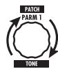
MIDI PCMODE 6/28
IMAPPING
4. Turn the [TYPE] knob to bring up the "PC MAP" (program change map) parameter.
Using this display, you can assign any patch of the G9.2tt to a program change number from 0 - 127.
![ZOOM G92TT - Turn the [TYPE] knob to bring up the "PC MAP" (program change map) parameter. - 1](/content/2025/01/152275/images/a046e93adbb13b5f73e6e4edb8f27e4a476f39e8a65444f39b95fcb448e65133.jpg)
- To assign a patch to a program change number, proceed as follows.
(1) Turn parameter knob 1 until the program change number to use is shown on the top line of the display.
![ZOOM G92TT - Turn the [TYPE] knob to bring up the "PC MAP" (program change map) parameter. - 2](/content/2025/01/152275/images/ef8746ca631fcafc1f5e6e0d84b92318b1996f102433d237e4e67f7e70a9b0ae.jpg)
(2) Use parameter knobs 2 and 3 to select the group name/bank number and patch number to assign to the program change number.
![ZOOM G92TT - Turn the [TYPE] knob to bring up the "PC MAP" (program change map) parameter. - 3](/content/2025/01/152275/images/519cf3596a313612c61a180de5c434bfc7dddad87380c2ffd254ee2268716032.jpg)
PC MAP 0Pr9:10
0Brk:A90Pat:3
(3) Repeat these steps to for other program change numbers.
6. When the setting is complete, press the [EXIT] key to exit the AMP SELECT/System menu.
The indication "Store...?" appears on the display, to allow you to store the changes.
7. Press the [STORE/SWAP] key to save the changes.
The setting is accepted, and the unit returns to play mode.
In the above condition, only the [STORE/SWAP] key and [EXIT] keys are active. By pressing the [EXIT] key, you can abort the changes and return to play mode without saving.
- To send and receive program change messages, proceed as described in step 6 of "Using direct mode" ( p. 45).
Sending and receiving pedal/switch/key operation information via MIDI (control change)
The G9.2tt allows sending and receiving control change messages via MIDI. These messages govern actions such as operating the expression pedals 1/2 , and switching modules or bypass/mute on and off with keys and foot switches. Each action can be assigned its own control change number (CC#).
■ Enable control change send/ receive
The procedure for enabling send/receive of control change messages is described below.
- In play mode, press the [AMP SELECT/System] key.

AMP Select 1/28 FRONT
- To enable the G9.2tt to receive control change messages, turn the [TYPE] knob to bring up the "MIDI CTRL Rx" (receive control change) parameter, and turn parameter knob 1 to select the "ON" setting.
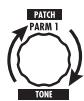
- When the setting is complete, press the [EXIT] key to exit the AMP SELECT/System menu.
The indication "Store...?" appears on the display, to allow you to store the changes.

Store...? Y[STORE]N[EXIT]
- Press the [STORE/SWAP] key to save the changes.
The setting is accepted, and the unit returns to play mode.
In the above condition, only the [STORE/SWAP] key and [EXIT] keys are active. By pressing the [EXIT] key, you can abort the changes and return to play mode without saving.
■Assigning control change numbers
You can assign control change numbers to the expression pedal and keys of the G9.2tt as follows.
NOTE
Before carrying out the following steps, verify that the send/receive MIDI channel setting of the G9.2tt is as required ( p. 43), and that send/receive of control change messages is enabled ( p. 47).
- In play mode, press the [AMP SELECT/SYSTEM] key.

AMP Select 1/28
- Turn the [TYPE] knob to bring up the display for assigning a control change number.
Operations to which a control change number can be assigned are listed in the table on the next page.
For example, to assign a control change number to expression pedal 1, the following display is used.

MIDI cc# 12/28 PEDAL1=7
Control change number to be assigned
HINT
The control change number assignment always applies both for sending and receiving.
- Turn parameter knob 1 to specify a control change number.

MIDI cc# 12/28
PEDAL1=7
| Display | Control target | Default CC# | CC# setting range |
| PEDAL1 | Expression pedal 1 operation | 7 | OFF, 1 - 5, 7 - 31, 64 - 95 |
| PEDAL2-U | Expression pedal 2 operation, vertical direction | 11 | OFF, 1 - 5, 7 - 31, 64 - 95 |
| PEDAL2-H | Expression pedal 2 operation, horizontal direction | 12 | OFF, 1 - 5, 7 - 31, 64 - 95 |
| COMP | COMP module on/off | 64 | OFF, 64 - 95 |
| WAH/EFX1 | WAH/EFX1 module on/off | 65 | OFF, 64 - 95 |
| EXT LOOP | EXT LOOP module on/off | 66 | OFF, 64 - 95 |
| ZNR | ZNR module on/off | 67 | OFF, 64 - 95 |
| PRE-AMP | PRE-AMP module on/off | 68 | OFF, 64 - 95 |
| EQUALIZER | EQ module on/off | 69 | OFF, 64 - 95 |
| MOD/EFX2 | MOD/EFX2 module on/off | 70 | OFF, 64 - 95 |
| DELAY | DELAY module on/off | 71 | OFF, 64 - 95 |
| REVERB | REVERB module on/off | 72 | OFF, 64 - 95 |
| MUTE | Mute mode on/off | 73 | OFF, 64 - 95 |
| BYPASS | Bypass mode on/off | 74 | OFF, 64 - 95 |
| CH A/B | Pre-amp section channel A/B switching | 75 | OFF, 64 - 95 |
- Assign control change numbers to other operations in the same way.
- When the setting is complete, press the [EXIT] key to exit the AMP SELECT/System menu.
The indication "Store...?" appears on the display, to allow you to store the changes.
6. Press the [STORE/SWAP] key to save the changes.
The setting is accepted, and the unit returns to play mode.
In the above condition, only the [STORE/SWAP] key and [EXIT] keys are active. By pressing the [EXIT] key, you can abort the changes and return to play mode without saving.
- To send and receive control change messages, connect the G9.2tt and the other MIDI device as follows.
Example for sending control change messages
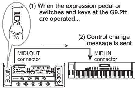
Control change values sent from the G9.2tt change as follows.
- When the expression pedal 1/2 is operated
The value of the assigned control change number is varied continuously over the range of 0-127. For expression pedal 2, two control change messages can be sent simultaneously, for vertical direction and horizontal direction movement.
- When module on/off switching is performed
When the module is set to on, the value 127 of the control change number is sent. When the module is set to off, the value 0 of the control change number is sent.
- When bypass/mute on/off switching is performed
When bypass/mute is set to on, the value 127 of the control change number is sent. When bypass/mute is set to off, the value 0 of the control change number is sent.
- When pre-amp section channel A/B switching is performed
When switching to channel A, the value 0 of the control change number is sent. When switching to channel B, the value 127 of the control change number is sent.
Example for receiving control change messages
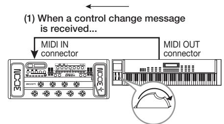
(2) The same operation as when the respective expression pedal or switch or key at the G9.2tt is operated occurs.
According to the control change value received, the G9.2tt status and parameter values change as follows.
- When control change for expression pedal 1/2 is received
The value of the parameter assigned to the pedal changes according to the control change value (0 - 127).
- When control change for module on/off is received
If control change value is between 0 and 63, the module is switched off. If control change value is between 64 and 127, the module is switched on.
- When control change for bypass/mute on/off is received
If control change value is between 0 and 63, bypass/mute is switched off. If control change value is between 64 and 127, bypass/mute is switched on.
- When control change for pre-amp section channel A/B switching is received
If control change value is between 0 and 63, the pre-amp section switches to channel A. If control change value is between 64 and 127, the pre-amp section switches to channel B.
Sending and receiving G9.2tt internal data via MIDI
The patch data stored in a G9.2tt can be sent and received as MIDI messages (system exclusive). When two G9.2tt units are connected via a MIDI cable, this allows copying of patch data from the sending unit to the receiving unit.
NOTE
When patch data are received, all existing patch data in the G9.2tt will be overwritten. Perform the following steps with care, to avoid accidentally overwriting important data.
1. Connect the MIDI OUT connector on the source G9.2tt to the MIDI IN connector on the target G9.2tt using a MIDI cable.
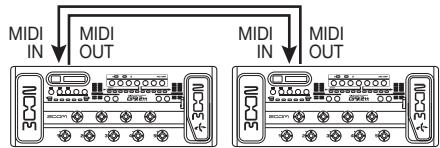
The steps at the target G9.2tt and source G9.2tt are explained separately below.
Target G9.2tt
2. Set the G9.2tt to play mode and press the [AMP SELECT/System] key. Then use the [TYPE] knob to bring up the "BulkDumpRX" (bulk dump receive) parameter on the display.
![ZOOM G92TT - Set the G9.2tt to play mode and press the [AMP SELECT/System] key. Then use the [TYPE] knob to bring up the "BulkDumpRX" (bulk dump receive) parameter on the display. - 1](/content/2025/01/152275/images/3632b07563d635aa4f191dfa8c8004e3cf974a6bb2c78411ea82c4886ab9deb9.jpg)
BulkDumperRX 28/28
ExtePress[PAGE]
3. Press the [PAGE] key.
The G9.2tt is switched to bulk dump target operation, and a MIDI message requesting data is sent repeatedly to the source G9.2tt.
Source G9.2tt
4. Set the G9.2tt to play mode and press the [AMP SELECT/System] key.
![ZOOM G92TT - Set the G9.2tt to play mode and press the [AMP SELECT/System] key. - 1](/content/2025/01/152275/images/8cc9d44ddbb4de450bede1d2cb59105b1f03590c605fb2a67a31f1eab3f5eea0.jpg)
AMP Select 1/28
5. Use the [TYPE] knob to bring up the "BulkDumpTx" (bulk dump transmit) parameter on the display.
![ZOOM G92TT - Use the [TYPE] knob to bring up the "BulkDumpTx" (bulk dump transmit) parameter on the display. - 1](/content/2025/01/152275/images/1f479319a9bda1256ff1c869d5768acaea449c206eaf676d1d6d8ada929349f8.jpg)
BulkDumFTX 27/28
ExtePress[PAGE]
6. Press the [PAGE] key.
The G9.2tt is switched to the bulk dump source standby condition. In this condition, the G9.2tt will automatically send patch data when it receives a MIDI message requesting data.
While the target G9.2tt is receiving data, the display changes as follows.
PatchDataDump RX Receiving ...
HINT
If you press the [EXIT] key before the indication "Receiving..." appears, the patch data send/ receive operation is aborted and the previous display returns.
When the patch data send/receive process is completed, both G9.2tt units return to the AMP SELECT/System menu.
HINT
The web site of ZOOM Corporation (http://www.zoom.co.jp) has editor/librarian software available for download. Using this software, you can store patch data of the G9.2tt on a computer.
Other Functions
Using the ARRM function
The G9.2tt incorporates an innovative feature called ARRM (Auto-Repeat Real-time Modulation) which uses various internally generated control waveforms to cyclically modify effect parameters. You can select for example a triangular waveform and apply it to the wah frequency as a control target. The resulting effect is shown below.
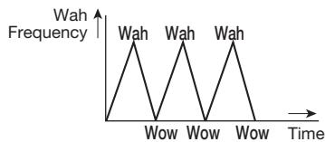
This section explains the use of the ARRM feature.
- In play mode, select the patch.
HINT
The ARRM settings can be made separately for each patch.
- Press the [TOTAL/FUNCTION] effect module key to switch to edit mode, and then turn the [TYPE] knob to bring up the indication "ARRM" on the display.
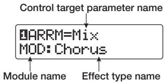
- Turn parameter knob 1 to select the control target parameter.
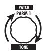
As you turn parameter knob 1, the effect parameter, effect type, and effect module change.
HINT
- The parameters that can be selected as control targets are the same as can be selected for operation by the expression pedal. See the section "Effect Types and Parameters" on page 60 - 75.
-
When "NOT Assign" is displayed, no parameter is assigned as control target and the ARRM function is disabled.
-
To set the adjustment range for the parameter to be controlled, use parameter knob 2 (minimum value) and parameter knob 3 (maximum value).
The settings selected with parameter knobs 2 and 3 determine the value when the control waveform reaches minimum value and maximum value.
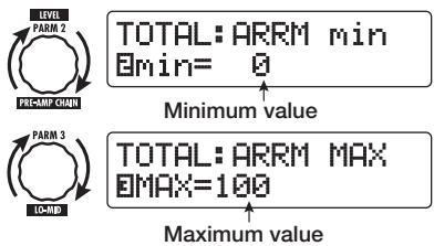
The difference between a parameter setting range of 0 (minimum) - 100 (maximum) and 20 (minimum) - 80 (maximum) is evident from the graph on the next page.
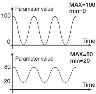
HINT
- The available range setting depends on the parameter.
-
It is also possible to set "min" to a higher value than "MAX". In that case, the control change direction will be reversed.
-
To select the control waveform type and cycle, press the [PAGE] key once to switch the page.

The ARRM function has a total of five parameters. To set parameters 4 and 5, press the [PAGE] key first and then use parameter knobs 1 and 2. (To return to adjusting parameters 1 - 3, press the [PAGE] key once more.)
- Turn parameter knob 1 to select the control waveform.
The display changes as follows.
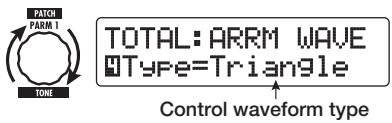
Available waveforms are shown at right.
| 1 | M | Rising sawtooth (Up Saw) |
| 2 | M | Rising fin (Up Curve) |
| 3 | N | Falling sawtooth (Down Saw) |
| 4 | N | Falling fin (Down Curve) |
| 5 | M | Triangle (Triangle) |
| 6 | M | Square triangle (Square Tri) |
| 7 | M | Sine wave (Sine) |
| 8 | M | Square wave (Square) |
- Turn parameter knob 2 to select the control waveform cycle.
The display changes as follows.

TOTAL:ARRM SYNC BSync=1x2
The control waveform cycle uses the patch specific tempo ( p. 39) as reference and is displayed as eighth note, quarter note, or quarter note x numeral (see table on page 40).
The numeral after x (2 - 20) indicates the duration of a cycle in multiple quarter notes. When "2" is selected, the control waveform changes in a cycle interval that corresponds to half a note of the patch specific tempo. When "4" is selected, the cycle is 4 beats (1 measure of a 4/4 beat).
- When the ARRM setting is complete, press the [EXIT] key.

The unit returns to play mode. Store the patch as necessary.
When you play your guitar in this condition, the selected effect parameter will be modified cyclically by the internally generated control waveform.
NOTE
Any changes in ARRM settings will be lost when you select a new patch. Be sure to store the patch if you want to keep the changes ( p. 28).
Using the G9.2tt as audio interface for a computer
By connecting the USB port of the G9.2tt to a USB port on a computer, the G9.2tt can be used as an audio interface with integrated AD/DA converter and effects. The operating environment conditions for this type of use are as follows.
Compatible operating system
- Windows XP
Mac OS X (10.2 and later)
Quantization
16-bit
Sampling frequencies
32kHz / 44.1kHz / 48kHz
HINT
With each of the operating systems listed above, the G9.2tt will function as an audio interface simply by connecting the USB cable. There is no need to install any special driver software.
NOTE
The USB port of the G9.2tt only serves for sending and receiving audio data. For MIDI messages, use the MIDI IN/OUT connectors.
To use the G9.2tt as an audio interface for the computer, connect the USB port of the G9.2tt to a USB port on the computer. The G9.2tt will be recognized as an audio interface.
In this condition, the sound of a guitar connected to the INPUT jack of the G9.2tt can be processed with the effects of the G9.2tt and then be recorded on the audio tracks of a DAW (Digital Audio Workstation) software application on the computer (see Figure 1 below).
When performing playback with the DAW application, the playback sound from the audio
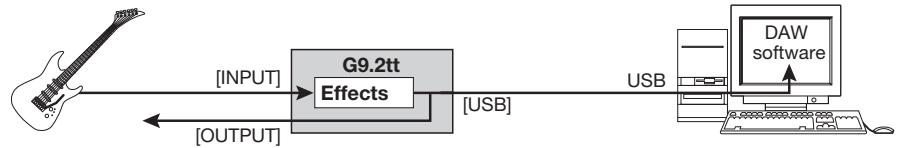
Fig. 1: Signal flow during recording
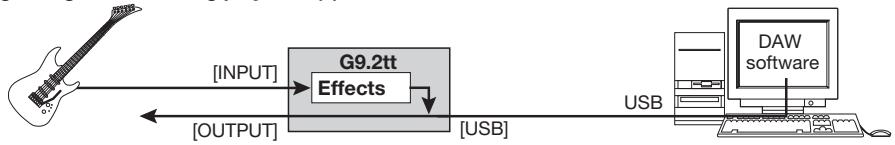
Fig. 2: Signal flow during playback (1)
Fig. 3: Signal flow during playback (2)
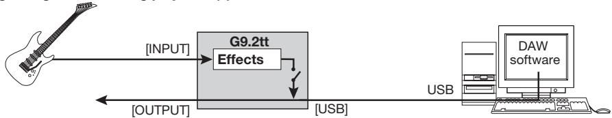

USB Monitor 3/28 USB+DIRECT
3. Turn parameter knob 1 to select one of the following settings.
- USB+DIRECT
The signal after effect processing appears at the OUTPUT jack also when USB connection is used.
- USB Only
The signal after effect processing at the OUTPUT jack is muted when USB connection is used.
4. When the setting is complete, press the [EXIT] key.
HINT
The USB Monitor setting is reset to the default condition (USB+DIRECT) when power is turned off and on again.
tracks is mixed with the guitar sound processed by the effects of the G9.2tt and appears at the OUTPUT jack of the G9.2tt (see Figure 2 on the previous page).
If required, the guitar signal after effect processing can be muted during playback (see Figure 3 on the previous page). For details, see next section.
For details on recording and playback, refer to the documentation of the DAW application.
NOTE
- If the DAW application has an echo back function (input signal during recording is supplied directly to an output), this must be disabled when using the G9.2tt with the direct output enabled. If recording is carried out with the echo back function on, the output signal may sound as if processed by a flanger effect, or the direct output signal may sound delayed.
- Use a high-quality USB cable and keep the connection as short as possible.
Muting the direct output when using a USB connection
When the G9.2tt is connected to a computer and used as an audio interface, the signal appearing at the OUTPUT jack after effect processing may be muted if required. To do this, proceed as follows.
1. In play mode, press the [AMP SELECT/System] key.
The AMP SELECT/System menu for parameters that apply to all patches appears.
![ZOOM G92TT - In play mode, press the [AMP SELECT/System] key. - 1](/content/2025/01/152275/images/d947b4cd9849b63c7463b8eed93d4b5c9a30bfbdc4bf61c8868b8576bc35ba50.jpg)
AMP Select 1/28 FRONT
2. Turn the [TYPE] knob to bring up the indication "USB Monitor" (output mode when USB connection is used) on the display.
About the editor/librarian software
ZOOM CORPORATION makes an editor/ librarian software application available for download on its web site.
To use the software, the computer must have a MIDI interface, and a connection must be established between the MIDI IN/MIDI OUT connectors of the computer and the MIDI OUT/MIDI IN connectors of the G9.2tt. The software then makes it possible to save patch data of the G9.2tt on the computer, edit the data, and copy edited patch data back to the G9.2tt.
Web site of ZOOM CORPORATION
http://wwwzoomo.co.jp
Adjusting the display contrast
If required, you can adjust the display contrast as follows.
1. In play mode, press the [AMP SELECT/SYSTEM] key.
The AMP SELECT/System menu for parameters that apply to all patches appears.
![ZOOM G92TT - In play mode, press the [AMP SELECT/SYSTEM] key. - 1](/content/2025/01/152275/images/fac1f6b5df766299f7b7131be2f54a509545dcc63b4906ac5abe188155dca8cb.jpg)
AMP Select 1/28 FRONT
2. Turn the [TYPE] knob to bring up the indication "Contrast" (display contrast) on the display.
![ZOOM G92TT - Turn the [TYPE] knob to bring up the indication "Contrast" (display contrast) on the display. - 1](/content/2025/01/152275/images/633813827cbdb0c4db4b20dc2f9506521101bf599c717662d8e2426e41ef3687.jpg)
LCD 2/28
Contrast:2
3. Turn parameter knob 1 to adjust the contrast in the range from 1 - 3.

LCD 2/28Contrast:3
4. When the setting is complete, press the [EXIT] key to exit the AMP SELECT/System menu.
The indication "Store...?" appears on the display, to allow you to store the changes.
![ZOOM G92TT - When the setting is complete, press the [EXIT] key to exit the AMP SELECT/System menu. - 1](/content/2025/01/152275/images/ec41ea9cf3c87aef115d412ab0aacbb46a436c120a5a949279b862cad8cb20ad.jpg)
Store...?
Y[STORE] N[EXIT]
5. Press the [STORE/SWAP] key to save the changes.
![ZOOM G92TT - Press the [STORE/SWAP] key to save the changes. - 1](/content/2025/01/152275/images/c7e80944f261770d9af01c131fede4c24f5eff4b953fdbf587df4e02a93be1d2.jpg)
The contrast setting is accepted, and the unit returns to play mode.
In the above condition, only the [STORE/SWAP] key and [EXIT] keys are active. By pressing the [EXIT] key, you can abort the changes and return to play mode without saving.
Linking Effects
The patches of the G9.2tt can be thought of as ten serially linked effect modules, as shown in the illustration below. You can use all effect modules together or selectively set certain modules to off to use just specific effect modules.
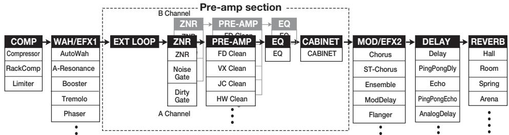
For some effect modules, you can select an effect type from several possible choices. For example, the MOD/EFX2 module comprises CHORUS, FLANGER, and other effect types from which you can choose one.
The five-module series EXT LOOP, ZNR, PRE-AMP, EQ, and CABINET functions as a virtual preamplifier with two channels. The ZNR, PRE-AMP, and EQ modules can have different settings for channels A and B, allowing channel switching also within the same patch.
the PRE-AMP module. This algorithm optimizes the sound for playing through a guitar amp. When the G9.2tt is connected to a guitar amp, this setting is recommended.
- When CABINET module is on
The direct recording algorithm is selected for the PRE-AMP module. This algorithm optimizes the sound for reproduction via a system with flat response. When the G9.2tt is connected to a recorder or hi-fi audio system, this setting is recommended.
Switching between live performance sound and direct recording sound
The PRE-AMP module of the G9.2tt comprises a total of 44 effect types. In addition, each of these effect types has two algorithms, one for live playing and one for direct recording. This amounts to having access to 88 effect types.
The respective algorithm is selected automatically, depending on the status of the CABINET module, as described below.
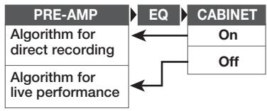
NOTE
When the CABINET module is off, the Amp Select function for matching the G9.2tt to the amplifier in use is also available. For details, see the next section.
- When CABINET module is off
The live performance algorithm is selected for
Using the Amp Select Function
The G9.2tt incorporates an Amp Select function that optimizes the frequency response to match the type of amplifier in use. When starting to use the G9.2tt or when changing the guitar amp, you should choose a suitable Amp Select setting as described below.
NOTE
The Amp Select feature is disabled for patches where the CABINET module is set to on. This is because the PRE-AMP module algorithm for direct recording will be automatically selected when the CABINET module is on.
1. In play mode, press the [AMP SELECT/SYSTEM] key.
![ZOOM G92TT - In play mode, press the [AMP SELECT/SYSTEM] key. - 1](/content/2025/01/152275/images/fd6e14f5cd4547cff3362eb2174650fde5d9d540da8481e95c60fd7de20bf033.jpg)
AMP Select 1/28
■FRONT
2. Turn parameter knob 1 to select one of the following settings.
FRONT
This is the standard setting for using the GUITAR INPUT on the front of the guitar amp.
COMBO R1
This setting is suitable when using the POWER INPUT on the rear panel of a Roland JC-120 guitar amp.
COMBO R2
This setting is suitable when using the POWER INPUT on the rear panel of a Fender combo amp.
STACK R
This setting is suitable when using the POWER
INPUT on the rear panel of a Marshall stack amp.
3. When the setting is complete, press the [EXIT] key.
The indication "Store...?" appears on the display, to allow you to store the changes.
4. Press the [STORE/SWAP] key to save the changes.
In the above condition, only the [STORE/SWAP] key and [EXIT] keys are active. By pressing the [EXIT] key, you can abort the changes and return to play mode without saving.
Changing the insert position of the pre-amp section and WAH/EFX1 module
The G9.2tt allows you to change the insert position of the five modules making up the pre-amp section (EXT LOOP, ZNR, PRE-AMP, EQ, CABINET) and the WAH/EFX1 module. This will result in changes to the effect action and tone.
Changing the insert position of the WAH/EFX1 module
To change the insert position of the WAH/EFX1 module, call up the Position parameter and set it to "Befr" (before pre-amp section) or "Aftr" (after pre-amp section). The Position parameter can be used when the Booster, Tremolo, or Octave effect type is not selected.
- In play mode, manual mode, or edit mode, press the [WAH/EFX1] key.
- Turn the [TYPE] knob and select an effect type other than Booster, Tremolo, or Octave.
- Turn parameter knob 1 to select "Befr" (before pre-amp section) or "Aftr" (after pre-amp section).
4. When the setting is complete, press the [EXIT] key.
The unit returns to the previous mode. To enable the changed setting, be sure to store the patch ( p.28)
Changing the insert position of the pre-amp section
To change the insert position of the pre-amp section, call up the Chain parameter and set it to "Pre" (before MOD/EFX2 module) or "Post" (after DELAY module). The Chain parameter can be used with all effect types of the PRE-AMP module.
1. In play mode, manual mode, or edit mode, press the [PRE-AMP] key.
The display changes as follows.
![ZOOM G92TT - In play mode, manual mode, or edit mode, press the [PRE-AMP] key. - 1](/content/2025/01/152275/images/8d206cd659bc806f2490b93522d5af202d2035c5d9bd785dbd137e5d3acca406.jpg)
3. When the setting is complete, press the [EXIT] key.
The unit returns to the previous mode. To enable the changed setting, be sure to store the patch ( p.28)
NOTE
- When the "Pre" setting is selected as pre-amp section insert position, the signal after the MOD/EFX2 module is processed entirely in stereo. When you select "Post", the signal is processed in the pre-amp section in mono.
- The pre-amp section insert position applies to both the A and B channel. Choosing a different setting for the two channels is not possible.
The module lineup with different settings for the WAH/EFX1 module and pre-amp section insertion position is shown below.
2. Turn parameter knob 2 to select "Pre" (before MOD/EFX2 module) or "Post" (after DELAY module).

Fig. 1 Pre-amp section = PRE, WAH/EFX1 = Befr

Fig. 2 Pre-amp section = PRE, WAH/EFX1 = Aftr

Fig. 3 Pre-amp section = POST, WAH/EFX1 = Befr

Fig. 4 Pre-amp section = POST, WAH/EFX1 = Aftr
Effect Types and Parameters
How to read the parameter table
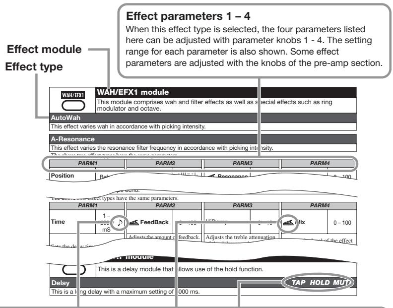
Tempo sync
The note symbol () in the table indicates that the parameter can be synchronized to the patch specific tempo. If you select the note symbol as value for the parameter when making the setting at the G9.2tt, the parameter value will be synchronized to the patch specific tempo in note units ( p. 39).
Expression pedal
The pedal symbol ( ) in the table indicates that the parameter can be controlled with the expression pedal 1/2. If you select the parameter as control target when making the setting at the G9.2tt ( p. 32 - 35), the expression pedal 1/2 will adjust the parameter in real time when the patch is selected. Parameters with the pedal symbol can also be selected as control targets for the ARRM function.
Delay tap/hold delay/delay mute
The tap (TAP), hold (HOLD), and mute (MUTE) symbols in the table indicate that the respective function foot switch 1/2 can be used to specify the delay time (TAP), toggle hold delay on and off (HOLD), or toggle mute between on and off (MUTE). These functions apply only to the DELAY module.
To use these functions, the respective function must be assigned to the function foot switch 1/2 p.38 and the respective effect type must be enabled.

COMP module

Attenuates high-level signal components and boosts low-level signal components, to keep the overall signal level within a certain range.
Compressor
This is an MXR Dynacomp type compressor.
| PARM1 | PARM2 | PARM3 | PARM4 | ||||
| Sense | 0-10 | Attack | Fast, Slow | Tone | 0-10 | Level | 2-100 |
| Adjusts the compressor sensitivity. Higher setting values result in higher sensitivity. | Selects compressor attack speed in two levels: Fast or Slow. | Adjusts the tonal quality of the sound. | Adjusts the signal level after passing the module. | ||||
RackComp
This effect type allows more detailed adjustment than "Compressor".
| PARM1 | PARM2 | PARM3 | PARM4 | ||||
| Threshold | 0-50 | Ratio | 1-10 | Attack | 1-10 | Level | 2-100 |
| Adjusts the reference signal level for the compressor action. | Adjusts the compression ratio. | Adjusts the compressor attack speed. | Adjusts the signal level after passing the module. | ||||
Limiter
This is a limiter that suppresses signal peaks above a certain reference level.
| PARM1 | PARM2 | PARM3 | PARM4 | ||||
| Threshold | 0-50 | Ratio | 1-10 | Release | 1-10 | Level | 2-100 |
| Adjusts the reference signal level for the limiter action. | Adjusts the compression ratio of the limiter. | Adjusts the delay between the point where the signal level falls below the threshold level and the limiter release. | Adjusts the signal level after passing the module. | ||||

WAH/EFX1 module
This module comprises wah and filter effects as well as special effects such as ring modulator and octave.
AutoWan
This effect varies wah in accordance with picking intensity.
See A-Resonance (next effect) for effect parameters.
A-Resonance
This effect varies the resonance filter frequency in accordance with picking intensity.
| PARM1 | PARM2 | PARM3 | PARM4 | ||||
| Position | Befr, Aftr | Sense | -10 -- 1, 1 - 10 | Resonance | 0 - 10 | Level | 2 - 100 |
| Selects the connection position of the WAH/EFX1 module. Available settings are "Befr" (before pre-amp section) or "Afr" (after pre-amp section). | Adjusts the effect sensitivity. | Adjusts the intensity of the resonance sound. | Adjusts the signal level after passing the module. | ||||
Booster
This is a booster for increasing signal gain.
| PARM1 | PARM2 | PARM3 | PARM4 | ||||
| Range | 1-5 | Tone | 0-10 | Gain | 0-10 | Level | 2-100 |
| Adjusts the frequency range to boost. | Adjusts the tonal quality of the sound. | Adjusts the amount of boost. | Adjusts the signal level after passing the module. | ||||
| Tremolo | |||||||
| This effect periodically varies the volume level. | |||||||
| PARM1 | PARM2 | PARM3 | PARM4 | ||||
| Depth | 0-100 | Rate | 0-50 | Wave | UP 0-9, DWN 0-9, TRI 0-9 | Level | 2-100 |
| Adjusts the modulation depth. | Adjusts the modulation rate. | Controls the modulation waveform. Available waveform types are "UP" (rising sawtooth), "DWN" (falling sawtooth), and "TRI" (triangular). Higher numerical values result in stronger clipping, which emphasizes the effect. | Adjusts the signal level after passing the module. | ||||
| Phaser | |||||||
| This effect produces a swooshing sound. | |||||||
| PARM1 | PARM2 | PARM3 | PARM4 | ||||
| Position | Befr, Aftr | Rate | 0-50° | Color | 1-4 | Level | 2-100 |
| Selects the connection position of the WAH/EFX1 module. Available settings are "Befr" (before pre-amp section) or "Aftr" (after pre-amp section). | Adjusts the modulation rate. | Adjusts the sound color. | Adjusts the signal level after passing the module. | ||||
| FixedPhaser | |||||||
| This effect provides a fixed phaser that can be used like an equalizer. | |||||||
| PARM1 | PARM2 | PARM3 | PARM4 | ||||
| Position | Befr, Aftr | Frequency | 1 - 50 | Color | 1 - 4 | Level | 2 - 100 |
| Selects the connection position of the WAH/EFX1 module. Available settings are "Befr" (before pre-amp section) or "Aftr" (after pre-amp section). | Adjusts the frequency range to emphasize. | Adjusts the sound color. | Adjusts the signal level after passing the module. | ||||
| RingModulate | |||||||
| This effect produces a metallic ringing sound. Adjusting the "Freq" parameter results in a drastic change of sound character. | |||||||
| PARM1 | PARM2 | PARM3 | PARM4 | ||||
| Position | Befr, Afrr | Frequency | 1 - 50 | Balance | 0 - 100 | Level | 2 - 100 |
| Selects the connection position of the WAH/EFX1 module. Available settings are "Befr" (before pre-amp section) or "Afrr" (after pre-amp section). | Adjusts the modulation frequency. | Adjusts the balance between original sound and effect sound. | Adjusts the signal level after passing the module. | ||||
| SlowAttack | |||||||
| This effect slows down the attack rate of the sound, resulting in a violin playing style sound. | |||||||
| PARM1 | PARM2 | PARM3 | PARM4 | ||||
| Position | Befr, Afr | Time | 1 - 50 | Curve | 0 - 10 | Level | 2 - 100 |
| Selects the connection position of the WAH/EFX1 module. Available settings are "Befr" (before pre-amp section) or "Afr" (after pre-amp section). | Adjusts the rise time. | Adjusts the rising volume change curve. | Adjusts the signal level after passing the module. | ||||
| PedalVox | |||||||
| Simulation of the vintage Vox pedal wah. | |||||||
| See PedalCry (next effect) for effect parameters. | |||||||
| PedalCry | |||||||
| Simulation of the vintage Crybaby pedal wah. | |||||||
| PARM1 | PARM2 | PARM3 | PARM4 | ||||
| Position | Befr, Afrr | Frequency | 1 - 50 | DryMix | 0 - 10 | Level | 2 - 100 |
| Selects the connection position of the WAH/EFX1 module. Available settings are "Befr" (before pre-amp section) or "Afr" (after pre-amp section). | Adjusts the frequency that is emphasized. When the expression pedals are not used, the effect is similar to a half open pedal. | Adjusts the level of the original sound mixed to the effect sound. | Adjusts the signal level after passing the module. | ||||
| MultiWah | |||||||
| This is a wah effect that allows selection of the curve in which the emphasized frequency moves. | |||||||
| PARM1 | PARM2 | PARM3 | PARM4 | ||||
| Position | Befr, Afr | Frequency | 1 - 50 | Curve | 1 - 10 | Level | 2 - 100 |
| Selects the connection position of the WAH/EFX1 module. Available settings are "Befr" (before pre-amp section) or "Afr" (after pre-amp section). | Adjusts the frequency that is emphasized. When the expression pedals are not used, the effect is similar to a half open pedal. | Adjusts the curve with which the frequency (PARM2) moves. | Adjusts the signal level after passing the module. | ||||
| P-Resonance | |||||||
| Pedal wah with a strong character. | |||||||
| PARM1 | PARM2 | PARM3 | PARM4 | ||||
| Position | Befr, Afr | Frequency | 1 - 50 | Resonance | 0 - 10 | Level | 2 - 100 |
| Selects the connection position of the WAH/EFX1 module. Available settings are "Befr" (before pre-amp section) or "Afr" (after pre-amp section). | Adjusts the modulation frequency. | Adjusts the resonance intensity. | Adjusts the signal level after passing the module. | ||||
| Octave | |||||||
| This effect adds a one-octave lower component to the original sound. | |||||||
| PARM1 | PARM2 | PARM3 | PARM4 | ||||
| OctLevel | 0-100 | DryLevel | 0-100 | Tone | 0-10 | Level | 2-100 |
| Adjusts the level of the one-octave lower sound component. | Adjusts the level of the original sound. | Adjusts the tonal quality of the lower octave component. | Adjusts the signal level after passing the module. | ||||
| EXT LOOP | EXT LOOP (external loop) module This module controls an external effect connected to the EXT LOOP SEND/RETURN jacks. The external effect send level and return level and the G9.2tt internal signal level can be set separately for each patch (→ p. 41). By setting this module to OFF, the external effect can be defeated . | |||||
| PARM1 | PARM2 | PARM3 | ||||
| SendLevel | 0 - 100 | RetLevel | 0 - 100 | DryLevel | 0 - 100 | |
| Adjusts the external effect send level. | Adjusts the external effect return level. | Adjusts the volume of the original sound in the G9.2tt (the signal level that is input to the EXT LOOP module). | ||||
| ZNR module This module serves for reducing noise during playing pauses. It offers a choice between noise reduction and noise gate (muting during pauses). | |
| ZNR (ZOOM NOISE REDUCTION) | |
| ZOOM original noise reduction which reduces noise in playing pauses without affecting the overall tone. | |
| NoiseGate | |
| This is a noise gate which cuts off the sound during playing pauses. | |
| DirtyGate | |
| This is a vintage type gate with special closing characteristics. |
The above three effect types have the same parameter.
| PARM1 | |
| Threshold | 1 – 16 |
| Adjusts the ZNR sensitivity. For maximum noise reduction, set the value as high as possible without causing the sound to decay unnaturally. | |
| PRE-AMP | PRE AMP module | ||
| This module comprises 43 types of distortion and an acoustic simulator. In edit mode, the module is adjusted using the [GAIN] and [LEVEL] knobs of the pre-amp section and the parameter knobs 1 and 2. For each effect type in this module, there are 2 algorithms (for live playing and direct recording). The algorithms are automatically selected according to the on/off status of the CABINET module (→ p. 67). Effect parameters are described below, after effect types. | |||
| FD Clean | VX Clean | ||
| Clean sound of a Fender Twin Reverb ('65 model) favored by guitarists of many music styles. | Clean sound of the combo amp VOX AC-30 operating in class A. | ||
| JC Clean | HW Clean | ||
| Clean sound of the Roland JC series with built-in chorus which gives a wide, clear tone. | Clean sound of the legendary all-tube Hiwatt Custom 100 from Britain. | ||
| UK Blues | US Blues | ||
| Crunch sound of the 30-watt combo amp Marshall 1962 Bluesbreaker. | Crunch sound of a Fender Tweed Deluxe '53. | ||
| TweedBass | BG Crunch | ||
| Crunch sound of the Fender Bassman, a bass amp with a strong presence. | Crunch sound of the Mesa Boogie MkIII combo amp. | ||
| VX Crunch | Z Combo | ||
| Crunch sound of class A combo amp Vox AC30TBX. | Zoom original combo amp crunch sound. | ||
| MS #1959 | MS Crunch | ||
| Crunch sound of the Marshall 1959 that has become legendary. | Crunch sound of the Marshall stack amp JCM800 that ranges from clean to crunch. | ||
| MS Drive | Rect Clin | ||
| High gain sound of the Marshall stack amp JCM2000. | Clean sound of the Mesa Boogie Dual Rectifier orange channel. | ||
| Rect Vnt | Rect Mdn | ||
| High gain sound of the Mesa Boogie Dual Rectifier red channel (Vintage mode). | High gain sound of the Mesa Boogie Dual Rectifier red channel (Modern mode). | ||
| HK Clean | HK Crunch | ||
| Clean sound of the Hughes & Kettner flagship model Triamp MKII (Amp 1). | Crunch sound of the Hughes & Kettner flagship model Triamp MKII (Amp 2). | ||
| HK Drive | DZ Clean | ||
| High gain sound of the Hughes & Kettner flagship model Triamp MKII (Amp 3). | Channel 1 clean sound of the hand-made German guitar amp Diezel Herbert with three separately controllable channels. | ||
| DZ Crunch | DZ Drive | ||
| Channel 2 crunch sound of the Diezel Herbert amp. | Channel 3 high gain sound of the Diezel Herbert amp. | ||
| ENGL Drv | PV Drive | ||
| Drive sound of the ENGL Ritchie Blackmore Signature 100. | High gain sound of a Peavey 5150 developed in cooperation with a world-famous hard rock guitarist. | ||
| Z Stack | OverDrive | ||
| Zoom original head amp high gain sound. | Simulation of the Boss OD-1 that first created the "overdrive" concept. | ||
| TS808 | Centaur | ||
| Simulation of the often copied Ibanez TS808 used by many guitarists as a booster. | Simulation of the Klon Centaur favored by many pros, also as a booster. | ||
| Guv'nor | RAT | ||
| Simulation of the Guv'nor distortion effect from Marshall. | Simulation of the PROCO Rat famous for its edgy distortion sound. | ||
| DS-1 | dist + | ||
| Simulation of the Boss distortion DS-1, a long-time favorite. | Simulation of MXR distortion+ that made distortion popular worldwide. | ||
| HotBox | FuzzFace | ||
| Simulation of the compact Matchless HotBox preamp with built-in tubes. | Simulation of the Fuzz Face that made rock history with its zany look and smashing sound. | ||
| BigMuff | MetalZone | ||
| Simulation of the Electro-Harmonix BigMuff preferred by famous artists for its fat, sweet fuzz sound. | Simulation of the Boss METALZONE with long sustain and dynamic lower midrange. | ||
| TS+F_Cmb | SD+M_Stk | ||
| Combination of Fender combo amp and Ibanez TS-9 sound. | Combination of Marshall stack amp and Boss SD-1 sound. | ||
| FZ+M_Stk | Z OD | ||
| Combination of Fuzz Face and Marshall stack amp sound. | Zoom original overdrive with natural distortion. | ||
| ExtremeDS | DigiFuzz | ||
| High gain sound with the most powerful gain of any distortion effect in the world. | High gain fuzz sound with strong character. | ||
| Z Clean | |||
| Zoom original straight clean sound. | |||
| The above 43 effect types have the same parameters. | |||
| GAIN | LEVEL | ||
| Gain | 0-10 | Level | 1-100 |
| Adjusts the preamp gain (distortion depth). | Adjusts the signal level after passing the module. | ||
| PARM1 | PARM2 | ||
| Tone | 0-30 | Chain | Pre, Post |
| Adjusts the tonal quality of the sound. | Selects the connection position of the pre-amp section. Available settings are "Pre" (before MOD/EFX2 module) or "Post" (after DELAY module). | ||
| Aco. Sim | |||
| This effect makes an electric guitar sound like an acoustic guitar. | |||
| GAIN | LEVEL | ||
| Top | 0-10 | Level | 1-100 |
| Adjusts the characteristic strings sound of an acoustic guitar. | Adjusts the signal level after passing the module. | ||
| PARM1 | PARM2 | ||
| Body | 0-10 | Chain | Pre, Post |
| Adjusts the characteristic body sound of an acoustic guitar. | Selects the connection position of the pre-amp section. Available settings are "Pre" (before MOD/EFX2 module) or "Post" (after DELAY module). | ||
| EQ module | |||||||
| This is a 6-band equalizer. In edit mode, the module is adjusted using the [BASS], [MIDDLE], [TREBLE], and [PRESENCE] knobs of the pre-amp section and the parameter knobs 3 and 4. | |||||||
| BASS | MIDDLE | TREBLE | PRESENCE | ||||
| Bass | ±12160Hz | Middle | ±12800Hz | Treble | ±123.2kHz | Presence | ±126.4kHz |
| Adjusts boost/cut in the low frequency range. | Adjusts boost/cut in the middle frequency range. | Adjusts boost/cut in the high frequency range. | Adjusts boost/cut in the very high frequency range. | ||||
| PARM3 | PARM4 | ||||||
| Low-Mid | ±12400Hz | Harmonics | ±1212kHz | ||||
| Adjusts boost/cut in the lower-middle frequency range. | Adjusts boost/cut in the harmonics frequency range. | ||||||
| CABINET module | ||||||
| This effect simulates the sound obtained when recording an amp cabinet with a microphone. The simulated mic type and position can be selected. The on/off status of this module controls the automatic algorithm selection in the PRE-AMP module (→ p. 65). | ||||||
| PARM1 | PARM2 | PARM3 | ||||
| MicType | Dyna, Cond | MicPosi | 0-2 | Depth | 0-2 | |
| Selects the microphone type. "Dyna" simulates the frequency response of a dynamic mic and "Cond" that of a condenser mic. | Lets you select different characteristics according to the mic position. The following settings are available. 0: Mic pointed at speaker center 1: Mic pointed halfway between speaker edge and center 2: Mic pointed at speaker edge | Adjusts the effect depth. Effect Depth 0 also includes some Cabinet sound. | ||||
| MOD/EFX2 | MOD/EFX2 module | ||||||
| This module comprises modulation effects such as chorus and flanger, delay effects, and pitch shifter effects. | |||||||
| Chorus | |||||||
| This effect mixes a variable pitch-shifted component to the original signal, resulting in full-bodied resonating sound. | |||||||
| PARM1 | PARM2 | PARM3 | PARM4 | ||||
| Depth | 0-100 | Rate | 1-50 | Tone | 0-10 | Mix | 0-100 |
| Adjusts the effect depth. | Adjusts the modulation rate. | Adjusts the tonal quality of the sound. | Adjusts the level of the effect sound mixed to the original sound. | ||||
| ST-Chorus | |||||||
| This is a clear sounding stereo chorus. | |||||||
| PARM1 | PARM2 | PARM3 | PARM4 | ||||
| Depth | 0-100 | Rate | 1-50 | Tone | 0-10 | Mix | 0-100 |
| Adjusts the effect depth. | Adjusts the modulation rate. | Adjusts the tonal quality of the sound. | Adjusts the level ofthe effect sound mixed to the original sound. | ||||
Ensemble
This is a chorus ensemble with three-dimensional movement.
ModDelay
| PARM1 | PARM2 | PARM3 | PARM4 | ||||
| Depth | 0-100 | Rate | 1-50 | Tone | 0-10 | Mix | 0-100 |
| Adjusts the effect depth. | Adjusts the modulation rate. | Adjusts the tonal quality of the sound. | Adjusts the level of the effect sound mixed to the original sound. | ||||
This is a delay that allows use of modulation.
Flanger
| PARM1 | PARM2 | PARM3 | PARM4 | ||||
| Time | 1-2000 mS | Feedback | 0-100 | Rate | 1-50 | Mix | 0-100 |
| Sets the delay time. | Adjusts the amount of feedback. Higher setting values result in a higher number of delay sound repetitions. | Adjusts the modulation rate. | Adjusts the level of the effect sound mixed to the original sound. | ||||
This effect produces a resonating and strongly undulating sound.
PitchShift
| PARM1 | PARM2 | PARM3 | PARM4 | ||||
| Depth | 0-100 | Rate | 0-50 | Resonance | -10--1, 0, 1-10 | Manual | 0-100 |
| Adjusts the effect depth. | Adjusts the modulation rate. | Adjusts the resonance intensity. | Adjusts the frequency range on which the effect operates. | ||||
This effect shifts the pitch up or down.
PedalPitch
| PARM1 | PARM2 | PARM3 | PARM4 | ||||
| Shift | -12 -- 1, 0, 1 - 12, 24 | Tone | 0 - 10 | Fine | -25 - 25 | Balance | 0 - 100 |
| Sets the pitch shift amount in semitones. | Adjusts the tonal quality of the sound. | Allows fine adjustment of pitch shift amount in Cent (1/100 semitone) steps. | Adjusts the balance between original sound and effect sound. | ||||
This effect allows using a pedal to shift the pitch in real time.
[Table 1]
| PARM1 | PARM2 | PARM3 | PARM4 | ||||
| Color | 1-8 | Mode | Up, Down | Tone | 0-10 | PdIPosi | 0-100 |
| Selects the type of pitch change caused by the pedal (see Table 1). | Sets the direction of the pitch change to Up or Down. | Adjusts the tonal quality of the sound. | Sets the pitch shift amount. Depending on the "Color" setting, the balance between original sound and effect sound also changes accordingly. | ||||
Color Mode Pedal minimum value Pedal maximum value Color Mode Pedal minimum value Pedal maximum value
Vibe
| 1 | Up Down | -100 cent Original sound only | Original sound only -100 cent | 5 | Up Down | -1 octave + DRY +1 octave + DRY | +1 octave + DRY -1 octave + DRY |
| 2 | Up Down | DOUBLING Detune + DRY | Detune + DRY DOUBLING | 6 | Up Down | -700 cent + DRY +500 cent + DRY | +500 cent + DRY -700 cent + DRY |
| 3 | Up Down | 0 cent +1 octave | +1 octave 0 cent | 7 | Up Down | -∞ (0 Hz) + DRY +1 octave | +1 octave -∞ (0 Hz) + DRY |
| 4 | Up Down | 0 cent -2 octaves | -2 octaves 0 cent | 8 | Up Down | -∞ (0 Hz) + DRY +1 octave + DRY | +1 octave + DRY -∞ (0 Hz) + DRY |
This is an effect with automatic vibrato.
Step
| PARM1 | PARM2 | PARM3 | PARM4 | ||||
| Depth | 0-100 | Rate | 0-50 | Tone | 0-10 | Balance | 0-100 |
| Adjusts the effect depth. | Adjusts the modulation rate. | Adjusts the tonal quality of the sound. | Adjusts the balance between original sound and effect sound. | ||||
Special effect that changes the sound in a staircase pattern.
Delay
| PARM1 | PARM2 | PARM3 | PARM4 | ||||
| Depth | 0-100 | Rate | 0-50 | Resonance | 0-10 | Shape | 0-10 |
| Adjusts the modulation depth. | Adjusts the modulation rate. | Adjusts the resonance intensity. | Adjusts the effect sound envelope. | ||||
This is a delay with a maximum setting of 2000 ms.
See TapeEcho (next effect) for effect parameters.
TapeEcho
This effect simulates a tape echo.
DynamicDelay
| PARM1 | PARM2 | PARM3 | PARM4 | ||||
| Time | 1-2000 mS | Feedback | 0-100 | HiDamp | 0-10 | Mix | 0-100 |
| Sets the delay time. | Adjusts the amount of feedback. Higher setting values result in a higher number of delay sound repetitions. | Adjusts the treble attenuation of the delay sound. Lower setting values result in softer delay sound. | Adjusts the level of the effect sound mixed to the original sound. | ||||
This is a dynamic delay where the effect volume varies according to the input signal level.
| PARM1 | PARM2 | PARM3 | PARM4 | ||||
| Time | 1-2000 mS | Amount | 0-100 | Feedback | 0-100 | Sense | -10 - -1, 1-10 |
| Sets the delay time. | Adjusts the level of the effect sound mixed to the original sound. | Adjusts the amount of feedback. | Adjusts the effect sensitivity. With positive setting values, the effect sound level increases at higher input signal levels. With negative setting values, the effect sound level decreases at higher input signal levels. | ||||
| DynamicFlang | |||||||
| This is a dynamic flanger where the effect volume varies according to the input signal level. | |||||||
| PARM1 | PARM2 | PARM3 | PARM4 | ||||
| Depth | 0-100 | Rate | 0-50 | Resonance | -10--1,0,1-10 | Sense | -10--1,1-10 |
| Adjusts the modulation depth. | Adjusts the modulation rate. | Adjusts the resonance intensity. | Adjusts the effect sensitivity. With positive setting values, the effect sound level increases at higher input signal levels. With negative setting values, the effect sound level decreases at higher input signal levels. | ||||
| MonoPitch | |||||||
| This is a pitch shifter specifically for monophonic sound (single-note playing), with little sound fluctuation. | |||||||
| PARM1 | PARM2 | PARM3 | PARM4 | ||||
| Shift | -24 - +24 | Tone | 0 - 10 | Fine | -25 - 25 | Balance | 0 - 100 |
| Adjusts the pitch shift amount in semitones. | Adjusts the tonal quality of the sound. | Allows fine adjustment of pitch shift amount in Cent (1/100 semitone) steps. | Adjusts the balance between original sound and effect sound. | ||||
| H.P.S (Harmonized Pitch Shifter) | |||||||
| This is an intelligent pitch shifter that automatically generates harmonies according to a preset key and scale. | |||||||
| PARM1 | PARM2 | PARM3 | PARM4 | ||||
| Scale | -6, -5, -4, -3, -m, m, 3, 4, 5, 6 | Key | C, C#, D, D#, E, F, F#, G, G#, A, A#, B | Tone | 0-10 | Mix | 0-100 |
| Determines the interval for the pitch shifted sound (see Table 2). | Determines the tonic for the scale used for pitch shifting. | Adjusts the tonal quality of the sound. | Adjusts the level of the effect sound mixed to the original sound. | ||||
[Table2]
| Setting | Type of scale | Interval | Setting | Type of scale | Interval |
| -6 | Major scale | Sixth down | 3 | Major scale | Third up |
| -5 | Fifth down | 4 | Fourth up | ||
| -4 | Fourth down | 5 | Fifth up | ||
| -3 | Third down | 6 | Sixth up | ||
| -m | Minor scale | Third down | |||
| m | Third up | ||||
| PdIMonoPitch | |||||||
| This is a pitch shifter specifically for monophonic sound (single-note playing), which allows the pitch to be shifted in real time with an expression pedal. | |||||||
| PARM1 | PARM2 | PARM3 | PARM4 | ||||
| Color | 1-8 | Mode | Up, Down | Tone | 0-10 | PdIPosi | 0-100 |
| Selects the type of pitch change caused by the pedal (see Table 1). | Sets the direction of the pitch change to Up or Down. | Adjusts the tonal quality of the sound. | Sets the pitch shift amount. Depending on the "Color" setting, the balance between original sound and effect sound also changes accordingly. | ||||
| Cry | |||||||
| This effect varies the sound like a talking modulator. | |||||||
| PARM1 | PARM2 | PARM3 | PARM4 | ||||
| Range | 1-10 | Resonance | 0-10 | Sense | -10--1, 1-10 | Balance | 0-100 |
| Adjusts the frequency range processed by the effect. | Adjusts the resonance intensity. | Adjusts the effect sensitivity. | Adjusts the balance between original sound and effect sound. | ||||
| ReverseDelay | |||||||
| This is a special delay where the effect sounds as if playing in reverse. | |||||||
| PARM1 | PARM2 | PARM3 | PARM4 | ||||
| Time | 10-1000 | Feedback | 0-100 | HiDamp | 0-10 | Balance | 0-100 |
| Sets the delay time. | Adjusts the amount of feedback. | Adjusts the treble attenuation of the delay sound. | Adjusts the balance between original sound and effect sound. | ||||
| BendChorus | |||||||
| This effect provides pitch bending that uses the input signal as trigger and processes each note separately. | |||||||
| PARM1 | PARM2 | PARM3 | PARM4 | ||||
| Depth | -50 - 50 | Attack | 1 - 10 | Release | 1 - 10 | Balance | 0 - 100 |
| Adjusts the effect depth. | Adjusts the attack time for the bending effect. Higher setting values result in slower attack. | Adjusts the release time for the bending effect. Higher setting values result in slower release. | Adjusts the balance between original sound and effect sound. | ||||
| CombFilter | |||||||
| This effect uses the comb filter characteristics generated by using fixed modulation on the flanger as an equalizer. | |||||||
| PARM1 | PARM2 | PARM3 | PARM4 | ||||
| Frequency | 1-50 | Resonance | -10-10 | HiDamp | 0-10 | Mix | 0-100 |
| Adjusts the frequency to be emphasized. | Adjusts the resonance intensity. | Adjusts the treble attenuation of the effect sound. | Adjusts the level of the effect sound mixed to the original sound. | ||||
| Air | |||||||
| This effect reproduces the ambience of a room, to create spatial depth. | |||||||
| PARM1 | PARM2 | PARM3 | PARM4 | ||||
| Size | 1-100 | Reflex | 0-10 | Tone | 0-10 | Mix | 0-100 |
| Adjusts the size of the simulated space. | Adjusts the amount of reflections from the wall. | Adjusts the tonal quality of the sound. | Adjusts the level of the effect sound mixed to the original sound. | ||||
| DELAY | DELAY module | |||||
| This is a delay module that allows use of the hold function. Effect parameters are described below, after effect types. | ||||||
| Delay | TAP HOLD MUTE | |||||
| This is a long delay with a maximum setting of 5000 ms. | ||||||
| PingPongDly | TAP HOLD MUTE | |||||
| This is a ping-pong type delay where the delay sound alternates between left and right. | ||||||
| Echo | TAP HOLD MUTE | |||||
| This effect simulates a tape echo with a long delay time of up to 5000 ms. | ||||||
| PingPongEcho | TAP HOLD MUTE | |||||
| This is a ping-pong type delay where the delay sound alternates between left and right. Long delay settings up to 5000 ms are possible. | ||||||
| AnalogDelay | TAP HOLD MUTE | |||||
| This effect simulates an analog delay with a long delay time of up to 5000 ms. | ||||||
| The above 5 effect types have the same parameters. | ||||||
| PARM1 | PARM2 | PARM3 | PARM4 | |||
| Time | 1-5000 | Feedback | 0-100 | HiDamp | 0-10 | Mix |
| Sets the delay time. | Adjusts the feedback amount. | Adjusts the treble attenuation of the effect sound. | Adjusts the level of the effect sound mixed to the original sound. | |||
| ReverseDelay | TAP HOLD MUTE | |||||
| This is a reverse delay with a long delay time of up to 2500 ms. | ||||||
| PARM1 | PARM2 | PARM3 | PARM4 | |||
| Time | 10-2500 | Feedback | 0-100 | HiDamp | 0-10 | Balance |
| Sets the delay time. | Adjusts the feedback amount. | Adjusts the treble attenuation of the effect sound. | Adjusts the balance between original sound and effect sound. | |||
| Air | ||||||
| This effect reproduces the ambience of a room, to create spatial depth. | ||||||
| PARM1 | PARM2 | PARM3 | PARM4 | |||
| Size | 1-100 | Reflex | 0-10 | Tone | 0-10 | Mix |
| Adjusts the size of the simulated space. | Adjusts the amount of reflections from the wall. | Adjusts the tonal quality of the sound. | Adjusts the level of the effect sound mixed to the original sound. | |||
| REVERB | REVERB module | ||||||
| This module comprises various kinds of reverb, early reflections, and multi-tap delay. Effect parameters are described below, after effect types. | |||||||
| Hall | |||||||
| This reverb effect simulates the acoustics of a concert hall. | |||||||
| Room | |||||||
| This reverb effect simulates the acoustics of a room. | |||||||
| Spring | |||||||
| This effect simulates a spring-type reverb. | |||||||
| Arena | |||||||
| This reverb effect simulates the acoustics of a large venue such as a sports arena. | |||||||
| TiledRoom | |||||||
| This reverb effect simulates the acoustics of a tiled room. | |||||||
| ModernSpring | |||||||
| This effect simulates a bright, transparent spring-type reverb. | |||||||
| The above six effect types have the same parameters. | |||||||
| PARM1 | PARM2 | PARM3 | PARM4 | ||||
| Decay | 1-30 | PreDelay | 1-100 | Tone | 0-10 | Mix | 0-100 |
| Sets the duration of the reverb. | Adjusts the delay between input of the original sound and start of the reverb sound. | Adjusts the tonal quality of the sound. | Adjusts the level of the effect sound mixed to the original sound. | ||||
| E/Reflection | |||||||
| This effect isolates only the early reflection components of the reverb. | |||||||
| PARM1 | PARM2 | PARM3 | PARM4 | ||||
| Decay | 1-30 | Shape | ±10 | Tone | 0-10 | Mix | 0-100 |
| Sets the duration of the reverb. | Adjusts the envelope of the effect sound. In the negative range, the envelope is reversed. At 0, the effect is a gate reverb. In the positive range, the envelope is an attenuating envelope. | Adjusts the tonal quality of the sound. | Adjusts the level of the effect sound mixed to the original sound. | ||||
| MultiTapDly | |||||||
| This effect produces several components with different delay times. | |||||||
| PARM1 | PARM2 | PARM3 | PARM4 | ||||
| Time | 1-3000 | Pattern | 1-8 | Tone | 0-10 | Mix | 0-100 |
| Sets the basic delay time. | Selects the combination pattern for the taps. The selection ranges from rhythmical to random patterns. | Adjusts the tonal quality of the sound. | Adjusts the level of the effect sound mixed to the original sound. | ||||
PanDelay
This is a stereo delay with a delay time of up to 3000 ms.
PingPongDly
| PARM1 | PARM2 | PARM3 | PARM4 | ||||
| Time | 1-3000 | Feedback | 0-100 | HiDamp | 0-10 | Pan | L50-L2,0,R2-R50 |
| Sets the delay time. | Adjusts the feedback amount. | Adjusts the treble attenuation of the effect sound. | Adjusts the panning (left/right) position of the sound. | ||||
This is a ping-pong delay with a delay time of up to 3000 ms.
See PingPongEcho (next effect) for effect parameters.
PingPongEcho
This is a ping-pong type delay where the delay sound alternates between left and right. Long delay settings up to 3000 ms are possible.
AutoPan
| PARM1 | PARM2 | PARM3 | PARM4 | ||||
| Time | 1-3000 | Feedback | 0-100 | HiDamp | 0-10 | Mix | 0-100 |
| Sets the delay time. | Adjusts the feedback amount. | Adjusts the treble attenuation of the effect sound. | Adjusts the level of the effect sound mixed to the original sound. | ||||
This effect cyclically moves the panning position of the sound.
| PARM1 | PARM2 | PARM3 | PARM4 | ||||
| Width | L50 - L2, 0, R2 - R50 | Rate | 0 - 50 | Depth | 0 - 10 | Wave | 0 - 10 |
| Adjusts the range of sound position movement. | Adjusts the modulation rate. | Adjusts the modulation depth. | Selects a waveform for modulation. Higher setting values result in stronger clipping, which emphasizes the auto-panning effect. | ||||
TOTAL/FUNCTION

TOTAL module
This module comprises parameters that affect the entire patch.
TOTAL
Specifies the patch specific tempo and the action of the function foot switches 1/2.
NAME
| PARM1 | PARM2 | PARM3 | |||
| Tempo | 40-250 | Function1 | See page 38 | Function2 | See page 38 |
| Specifies the patch specific tempo (→p. 39). | Selects the action of function foot switch 1. | Selects the action of function foot switch 2. | |||
Specifies a name for the patch ( ,27)
Makes settings for the ARRM function ( p. 52). Use the [PAGE] key to switch between page 1 and 2.
ARRM
| PAGE1 | ||||
| PARM1 | PARM2 | PARM3 | ||
| ARRM control target | min (minimum value) | See page 52 | MAX (maximum value) | See page 52 |
| Selects the ARRM control target. When "NOT Assign" is selected, the ARRM function is disabled. | Specifies the parameter value that is set when the control waveform reaches its lowest point. | Specifies the parameter value that is set when the control waveform reaches its highest point. | ||
P2V1 to P2V4 (Expression pedal 2, vertical direction setting)
| PAGE2 | |||
| PARM1 | PARM2 | ||
| Wave | See page 53 | Sync | See page 53 |
| Selects the control target waveform. | Specifies control waveform synchronization using the patch specific tempo as reference. | ||
P1-1 to P1-4 (Expression pedal 1 setting)
Specify control targets 1 - 4 for expression pedal 1. Effect parameters are described below, after effect types.
Specify control targets 1 - 4 for expression pedal 2 (vertical direction).
Specify control targets 1 - 4 for expression pedal 2 (horizontal direction).
The above 12 items have the same parameters. However, for P2H1 to P2H4 (pedal 2, horizontal direction setting), PARM4 (module on/off) is not available.
P2H1 to P2H4 (Expression pedal 2, horizontal direction setting)
| PARM1 | PARM2 | PARM3 | PARM4 |
| Expression pedal control target | min (minimum value) | MAX (maximum value) | Module on/off function |
| Specifies the expression pedal control target. | Specifies the parameter value that is set when the pedal is fully raised, or when pedal 2 is fully turned to the left. | Specifies the parameter value that is set when the pedal is fully pushed down, or when pedal 2 is fully turned to the right. | Enables or disables the module on/off function. This parameter is not available for P2H1 to P2H4 (pedal 2, horizontal direction setting). |
Troubleshooting
No sound or very low volume
- Make sure that the POWER switch is on.
Try adjusting the LEVEL knob. - Make sure that the INPUT jack and the guitar, and the OUTPUT L/MONO (or OUTPUT R) jack and the guitar amp are connected properly.
- Make sure that the shielded cable is not defective.
- Try adjusting the patch level ( p.16)
- Make sure that the G9.2tt is not in mute condition ( p. 21).
- For some patches, the volume can be adjusted with an expression pedal. Make sure that a suitable volume setting has been selected with the pedal.
- When both controls in the Accelerator section are fully turned down, there will be no sound. You must turn at least one control partially up.
Sound is distorted
- Try lowering the Gain and Level parameters of the PRE-AMP module.
- Try lowering the setting of the [TUBE] control and [BOOST] control in the Energizer section.
- Try lowering the setting of the [TUBE] control in the Accelerator section.
Foot switches do not operate properly
- Check the setting of function foot switches 1/2 p.38 .
- Check the current operation mode. The foot switch action is different in play mode and manual mode.
Sound in bypass condition is strange
- Try lowering the setting of the [TUBE] control and [BOOST] control in the Energizer section.
The Energizer operates also in the bypass condition.
- Set the [TUBE] control in the Accelerator section to a setting lower than 3 o'clock. The Accelerator operates also in the bypass condition.
Noise is noticeable
- Make sure that only a ZOOM AC adapter is used.
- Adjust the ZNR setting.
- Move around the room to check for RF noise in relation to the pick ups, etc.
- Try lowering the Gain and Level parameters of the PRE-AMP module.
- Check the settings of expression pedals 1/2 ( p. 33 - 35).
Depending on the parameter assigned to expression pedals 1/2 , a pedal action causing drastic parameter change may result in noise.
Cannot send or receive MIDI messages
- Make sure that the MIDI IN connector of the G9.2tt and the MIDI OUT connector of the other MIDI device, and the MIDI OUT connector of the G9.2tt and the MIDI IN connector of the other MIDI device are connected properly.
- Check the MIDI channel setting ( p.43) .
- Check whether send/receive of the respective type of MIDI message is enabled ( p. 44, 47).
On/off switching with expression pedal does not work properly
- Verify that parameter 4 (module on/off) for expression pedal 1 (P1-1 to P1-4) or the vertical direction of expression pedal 2 (P2V1 to P2V4) in the TOTAL module is set to "Enable" ( p. 33, 34).
- The module on/off function is not available for pedal 2, horizontal direction setting (P2H1 to P2H4). ( p. 34).
Specifications
| Number of effect types | 106 |
| Number of effect modules | 10 simultaneously usable modules |
| Patch memory | User area: 5 patches x 20 banks = 100 (read/write enabled) Preset area: 5 patches x 20 banks = 100 (read only) Total: 200 patches |
| Sampling frequency | 96 kHz |
| A/D conversion | 24-bit, 64-times oversampling |
| D/A conversion | 24-bit, 128-times oversampling |
| Signal processing | 32-bit |
| Frequency response | 20 Hz - 40 kHz +1.0 dB, -3.0 dB (10 kilohm load) |
| Display | 2-digit 7-segment LED display 16-digit 2-line backlit LCD |
| Inputs | |
| Guitar input | Standard monaural phone jack Rated input level: -10 dBm Input impedance: 1 megohm |
| AUX input | Mini phone jack (stereo) Rated input level: -10 dBm Input impedance: 10 kilohms |
| External Return | Standard mono phone jack Rated input level: -10 dBm/+4 dBm (switchable) |
| Outputs | |
| Line output | Standard monaural phone jack x 2 Rated output level: -10 dBm/+4 dBm (switchable) Maximum output level: +19 dBm (into load impedance of 10 kilohms or more) Output impedance: 1 kilohm or less |
| Headphone output | Standard stereo phone jack Rated output: 60 m W (into 32-ohm load), 20 m W (into 300-ohm load) Output impedance: 47 kilohm |
| External Send | Standard mono phone jack Rated output level: -10 dBm/+4 dBm (switchable) |
| Tube circuitry | 12AX7 x 2 |
| Control connectors | MIDI OUT, MIDI IN |
| USB interface | |
| PC interface | 16-bit (record/play, stereo) |
| Sampling frequencies | 32 kHz, 44.1 kHz, 48 kHz |
| Power requirements | 15 V AC, 1.5 A (from supplied AC adapter AD-0012) |
| Dimensions | 235 (D) x 595 (W) x 85 (H) mm |
| Weight | 5.5kg |
- 0 dBm = 0.775 Vrms
- Design and specifications subject to change without notice.
MIDI implementation chart
| [EFFECTOR Model G9.2tt] MIDI Implementation Chart | Date: 08.Oct.,2005 Version:1.00 | |||
| Function ... | Transmitted | Recognized | Remarks | |
| Basic Channel Changed | 1-16,OFF 1-16,OFF | 1-16,OFF 1-16,OFF | ||
| Mode Messages Altered | 3 x ********** | 3 x | ||
| Note Number | True voice | x ********** | x | ||
| Velocity Note ON Note OFF | x x | x x | ||
| After Key's Touch Ch's | x x | x x | ||
| Pitch Bend | x | x | ||
| Control Change | o 0,32 1-5,7-31,64-95 64-95 | o 0,32 1-5,7-31,64-95 64-95 | Bank select Expression Pedal 1, Expression Pedal 2 Effect module on/off, Signal mute,Bypass, Channel A/B (See Note 1) | |
| Prog Change | True # | o 0-99 ********** | o 0-127 | ||
| System Exclusive | o | o | ||
| System Common | Song Pos Song Sel Tune | x x x | x x x | ||
| System Real Time | Clock Commands | x x | x x | ||
| Aux Mes-sages | Local ON/OFF All Notes OFF Active Sense Reset | x x x | x x x | |
| x x x | x x x | |||
| Notes | 1. Control # 1-5,7-31,64-95 is assignable. 2. Transmit Control # and Recognized Control # that used in some function are same. | |||
G9.2tt patch/bank number + program number assignment table
| GROUP | BANK | PATCH No. | ||||||||||||||
| 1 | 2 | 3 | 4 | 5 | ||||||||||||
| Bank No. | Program No. | Bank No. | MSB | LSB | Program No. | MSB | LSB | Program No. | MSB | LSB | Program No. | MSB | LSB | Program No. | ||
| U | 0 | 0 | 0 | 0 | 0 | 0 | 1 | 0 | 0 | 2 | 0 | 0 | 3 | 0 | 0 | 4 |
| 1 | 0 | 0 | 5 | 0 | 0 | 6 | 0 | 0 | 7 | 0 | 0 | 8 | 0 | 0 | 9 | |
| 2 | 0 | 0 | 10 | 0 | 0 | 11 | 0 | 0 | 12 | 0 | 0 | 13 | 0 | 0 | 14 | |
| 3 | 0 | 0 | 15 | 0 | 0 | 16 | 0 | 0 | 17 | 0 | 0 | 18 | 0 | 0 | 19 | |
| 4 | 0 | 0 | 20 | 0 | 0 | 21 | 0 | 0 | 22 | 0 | 0 | 23 | 0 | 0 | 24 | |
| 5 | 0 | 0 | 25 | 0 | 0 | 26 | 0 | 0 | 27 | 0 | 0 | 28 | 0 | 0 | 29 | |
| 6 | 0 | 0 | 30 | 0 | 0 | 31 | 0 | 0 | 32 | 0 | 0 | 33 | 0 | 0 | 34 | |
| 7 | 0 | 0 | 35 | 0 | 0 | 36 | 0 | 0 | 37 | 0 | 0 | 38 | 0 | 0 | 39 | |
| 8 | 0 | 0 | 40 | 0 | 0 | 41 | 0 | 0 | 42 | 0 | 0 | 43 | 0 | 0 | 44 | |
| 9 | 0 | 0 | 45 | 0 | 0 | 46 | 0 | 0 | 47 | 0 | 0 | 48 | 0 | 0 | 49 | |
| u | 0 | 0 | 0 | 50 | 0 | 0 | 51 | 0 | 0 | 52 | 0 | 0 | 53 | 0 | 0 | 54 |
| 1 | 0 | 0 | 55 | 0 | 0 | 56 | 0 | 0 | 57 | 0 | 0 | 58 | 0 | 0 | 59 | |
| 2 | 0 | 0 | 60 | 0 | 0 | 61 | 0 | 0 | 62 | 0 | 0 | 63 | 0 | 0 | 64 | |
| 3 | 0 | 0 | 65 | 0 | 0 | 66 | 0 | 0 | 67 | 0 | 0 | 68 | 0 | 0 | 69 | |
| 4 | 0 | 0 | 70 | 0 | 0 | 71 | 0 | 0 | 72 | 0 | 0 | 73 | 0 | 0 | 74 | |
| 5 | 0 | 0 | 75 | 0 | 0 | 76 | 0 | 0 | 77 | 0 | 0 | 78 | 0 | 0 | 79 | |
| 6 | 0 | 0 | 80 | 0 | 0 | 81 | 0 | 0 | 82 | 0 | 0 | 83 | 0 | 0 | 84 | |
| 7 | 0 | 0 | 85 | 0 | 0 | 86 | 0 | 0 | 87 | 0 | 0 | 88 | 0 | 0 | 89 | |
| 8 | 0 | 0 | 90 | 0 | 0 | 91 | 0 | 0 | 92 | 0 | 0 | 93 | 0 | 0 | 94 | |
| 9 | 0 | 0 | 95 | 0 | 0 | 96 | 0 | 0 | 97 | 0 | 0 | 98 | 0 | 0 | 99 | |
| A | 0 | 1 | 0 | 0 | 1 | 0 | 1 | 1 | 0 | 2 | 1 | 0 | 3 | 1 | 0 | 4 |
| 1 | 1 | 0 | 5 | 1 | 0 | 6 | 1 | 0 | 7 | 1 | 0 | 8 | 1 | 0 | 9 | |
| 2 | 1 | 0 | 10 | 1 | 0 | 11 | 1 | 0 | 12 | 1 | 0 | 13 | 1 | 0 | 14 | |
| 3 | 1 | 0 | 15 | 1 | 0 | 16 | 1 | 0 | 17 | 1 | 0 | 18 | 1 | 0 | 19 | |
| 4 | 1 | 0 | 20 | 1 | 0 | 21 | 1 | 0 | 22 | 1 | 0 | 23 | 1 | 0 | 24 | |
| 5 | 1 | 0 | 25 | 1 | 0 | 26 | 1 | 0 | 27 | 1 | 0 | 28 | 1 | 0 | 29 | |
| 6 | 1 | 0 | 30 | 1 | 0 | 31 | 1 | 0 | 32 | 1 | 0 | 33 | 1 | 0 | 34 | |
| 7 | 1 | 0 | 35 | 1 | 0 | 36 | 1 | 0 | 37 | 1 | 0 | 38 | 1 | 0 | 39 | |
| 8 | 1 | 0 | 40 | 1 | 0 | 41 | 1 | 0 | 42 | 1 | 0 | 43 | 1 | 0 | 44 | |
| 9 | 1 | 0 | 45 | 1 | 0 | 46 | 1 | 0 | 47 | 1 | 0 | 48 | 1 | 0 | 49 | |
| b | 0 | 1 | 0 | 50 | 1 | 0 | 51 | 1 | 0 | 52 | 1 | 0 | 53 | 1 | 0 | 54 |
| 1 | 1 | 0 | 55 | 1 | 0 | 56 | 1 | 0 | 57 | 1 | 0 | 58 | 1 | 0 | 59 | |
| 2 | 1 | 0 | 60 | 1 | 0 | 61 | 1 | 0 | 62 | 1 | 0 | 63 | 1 | 0 | 64 | |
| 3 | 1 | 0 | 65 | 1 | 0 | 66 | 1 | 0 | 67 | 1 | 0 | 68 | 1 | 0 | 69 | |
| 4 | 1 | 0 | 70 | 1 | 0 | 71 | 1 | 0 | 72 | 1 | 0 | 73 | 1 | 0 | 74 | |
| 5 | 1 | 0 | 75 | 1 | 0 | 76 | 1 | 0 | 77 | 1 | 0 | 78 | 1 | 0 | 79 | |
| 6 | 1 | 0 | 80 | 1 | 0 | 81 | 1 | 0 | 82 | 1 | 0 | 83 | 1 | 0 | 84 | |
| 7 | 1 | 0 | 85 | 1 | 0 | 86 | 1 | 0 | 87 | 1 | 0 | 88 | 1 | 0 | 89 | |
| 8 | 1 | 0 | 90 | 1 | 0 | 91 | 1 | 0 | 92 | 1 | 0 | 93 | 1 | 0 | 94 | |
| 9 | 1 | 0 | 95 | 1 | 0 | 96 | 1 | 0 | 97 | 1 | 0 | 98 | 1 | 0 | 99 | |
The FCC regulation warning (for U.S.A.)
This equipment has been tested and found to comply with the limits for a Class B digital device, pursuant to Part 15 of the FCC Rules. These limits are designed to provide reasonable protection against harmful interference in a residential installation. This equipment generates, uses, and can radiate radio frequency energy and, if not installed and used in accordance with the instructions, may cause harmful interference to radio communications. However, there is no guarantee that interference will not occur in a particular installation. If this equipment does cause harmful interference to radio or television reception, which can be determined by turning the equipment off and on, the user is encouraged to try to correct the interference by one or more of the following measures:
- Reorient or relocate the receiving antenna.
- Increase the separation between the equipment and receiver.
- Connect the equipment into an outlet on a circuit different from that to which the receiver is connected.
- Consult the dealer or an experienced radio/TV technician for help.
Operating Dedicated Effects With the Z-Pedal
Besides the effects described in the manual, the WAH/EFX1, MOD/EFX2, and REVERB modules of the G9.2tt contain a number of special effect types that are designed to make best use of the capabilities offered by expression pedal 2 (Z-pedal). These effect types are described below.
Another additional function is the "ARRM BPM" parameter that can be assigned to an expression pedal. When this is done, the reference tempo for the ARRM function (0 - 250) can be controlled with the pedal. (The patch specific tempo setting is not affected.)
WAH/EFX1 module
X-Wah
This effect allows cross-fading of original sound and effect sound (VOX type wah), using the pedal. Try assigning the vertical direction of the Z-pedal (P2V1 - P2V4) to the "Frequency" parameter and the horizontal direction (P2H1 - P2H4) to the "X-Fade" parameter.
| PARM1 | PARM2 | PARM3 | PARM4 | ||||
| Position | Befr, Aftr | Frequency | 1 ̤ 50 | X-Fade | 0 ̤ 100 | Level | 2 ̤ 100 |
| Selects the connection position of the WAH/EFX1 module. Available settings are "Befr" (before pre-amp section) or "Aftr" (after pre-amp section). | Adjusts the frequency that is emphasized. | Adjust the level balance between original sound and effect sound. | Adjusts the signal level after passing the module. | ||||
X-Phaser
This effect allows cross-fading of original sound and effect sound (Phaser), using the pedal. Try assigning the vertical direction of the Z-pedal (P2V1 - P2V4) to the "Rate" parameter and the horizontal direction (P2H1 - P2H4) to the "X-Fade" parameter.
| PARM1 | PARM2 | PARM3 | PARM4 | ||||
| Color | Bef1 ̅n 4, Aft1 ̅n 4 | Rate | 0 ̅n 50 | X-Fade | 0 ̅n 100 | Level | 2 ̅n 100 |
| Selects the connection position and the sound type. With settings "Bef1" to "Bef4", the position is before the PRE-AMP module, and with settings "Aft1" to "Aft4" after the PRE-AMP module. | Adjusts the modulation rate. | Adjusts the level balance between original sound and effect sound. | Adjusts the signal level after passing the module. | ||||
X-Vibe
This effect allows cross-fading of phaser and tremolo action, using the pedal. Try assigning the vertical direction of the Z-pedal (P2V1/P2V4) to the "Rate" parameter and the horizontal direction to (P2H1 - P2H4) the "X-Fade" parameter.
| PARM1 | PARM2 | PARM3 | PARM4 | ||||
| PHA Rate | 0 n 50 J | TRM Rate | 0 n 50 J | X-Fade | 0 n 100 | Level | 2 n 100 |
| Adjusts the phaser modulation rate. | Adjusts the tremolo modulation rate. | Adjusts the level balance between phaser and tremolo. | Adjusts the signal level after passing the module. | ||||
Z-Oscillator
This oscillator allows changing its frequency by tracking the pitch of the guitar signal or with the pedal. A portamento and vibrato effect can also be added to the oscillator signal.
To have the oscillator frequency track the guitar pitch, set the "Frequency" parameter to "A-Bf" (before PRE-AMP module) or "A-Af" (after PRE-AMP module). In this case, try assigning the vertical direction of the Z-pedal (P2V1 - P2V4) to the "Balance" parameter and the horizontal direction (P2H1 - P2H4) to the "Portament" or "Vibrato" parameter.
To control the oscillator frequency with the pedal, set the "Frequency" parameter to 0 - 60 (this becomes the reference frequency) and assign the vertical direction of the Z-pedal to the "Frequency" parameter and the horizontal direction to the "Balance" parameter.
| PARM1 | PARM2 | PARM3 | PARM4 | ||||
| Frequency | 0 n 60, A-Bf, A-Af | Portament | 0 n 10 | Vibrato | 0 n 10 | Balance | 0 n 100 |
| Selects the oscillator frequency (see Table 1). | Adjusts the smoothness of the pitch change. | Adjusts the vibrato depth. | Adjust the level balance between original sound and effect sound. | ||||
Table 1
| Frequency parameter | Note | Frequency parameter | Note |
| 0 n 11 | A2 – Ab3 | 36 n 47 | A5 – Ab6 |
| 12 n 23 | A3 – Ab4 | 48 n 59 | A6 – Ab7 |
| 24 n 35 | A4 – Ab5 | 60 | A7 |
MOD/EFX2 module
Z-Echo
This effect allows changing the echo pitch and duration by controlling the "Time" parameter with the pedal. Try assigning the vertical direction of the Z-pedal (P2V1 - P2V4) to the "Time" parameter and the horizontal direction (P2H1 - P2H4) to the "FeedBack" or "Mix" parameter.
| PARM1 | PARM2 | PARM3 | PARM4 | ||||
| Time | 10 ñ 1000 | Feedback | 0 ñ 100 | HiDamp | 0 ñ 10 | Mix | 0 ñ 100 |
| Adjusts the delay time. | Adjusts the amount of feedback. Higher setting values result in a higher number of delay sound repetitions. | Adjusts the amount of treble damping in the delay sound. Lower setting values result in softer delay sound. | Adjusts the level of the effect sound mixed to the original sound. | ||||
X-Flanger
This effect allows cross-fading of original sound and effect sound (Flanger), using the pedal. Try assigning the vertical direction of the Z-pedal (P2V1 - P2V4) to the "Rate" parameter and the horizontal direction (P2H1 - P2H4) to the "X-Fade" parameter.
| PARM1 | PARM2 | PARM3 | PARM4 | ||||
| Depth | 0 n 100 | Rate | 0 n 50 | X-Fade | 0 n 100 | Manual | 0 n 100 |
| Adjusts the modulation depth. | Adjusts the modulation rate. | Adjust the level balance between original sound and effect sound. | Adjusts the frequency range in which the effect operates. | ||||
X-Step
This effect allows cross-fading of original sound and effect sound (Step), using the pedal. Try assigning the vertical direction of the Z-pedal (P2V1 - P2V4) to the "Rate" parameter and the horizontal direction (P2H1 - P2H4) to the "X-Fade" parameter.
| PARM1 | PARM2 | PARM3 | PARM4 | ||||
| Depth | 0 n 100 | Rate | 0 n 50 J | X-Fade | 0 n 100 | Shape | 0 n 10 |
| Adjusts the modulation depth. | Adjusts the modulation rate. | Adjust the level balance between original sound and effect sound. | Adjusts the envelope of the effect sound. | ||||
Z-Step
This is a step effect which allows shifting the emphasized frequency up or down, using the pedal. If you assign the "Frequency" parameter to the pedal, the emphasized frequency will change in discrete steps, until the target frequency is reached.
Try assigning the vertical direction of the Z-pedal (P2V1 - P2V4) to the "Frequency" parameter and the horizontal direction (P2H1 - P2H4) to the "Mix" parameter.
| PARM1 | PARM2 | PARM3 | PARM4 | ||||
| Frequency | 1 n 50 | Depth | 0 n 100 | Shape | 0 n 10 | Mix | 0 n 100 |
| Adjusts the emphasized frequency. | Adjusts the modulation depth. | Adjusts the envelope of the effect sound. | Adjusts the level of the effect sound mixed to the original sound. | ||||
Z-Pitch
This is a pitch shifter that allows setting a different pitch shift amount in the vertical and the horizontal direction of the Z-pedal.
Try assigning the vertical direction of the Z-pedal (P2V1 - P2V4) to the "PdIPosi V" parameter and the horizontal direction (P2H1 - P2H4) to the "PdIPosi H" parameter.
The parameters are the same as for Z-MonoPitch.
Z-MonoPitch
This is a monophonic pitch shifter (for single-note playing) that allows setting a different pitch shift amount in the vertical and the horizontal direction of the Z-pedal.
Try assigning the vertical direction of the Z-pedal (P2V1 - P2V4) to the "PdIPosi V" parameter and the horizontal direction (P2H1 - P2H4) to the "PdIPosi H" parameter.
| PARM1 | PARM2 | PARM3 | PARM4 | ||||
| Color | 1 ð 8 | Tone | 0 ð 10 | PdIPosi V | 0 ð 100 | PdIPosi H | 0 ð 100 |
| Selects the pitch change type caused by the pedal (see Table 2). | Adjusts the tone. | Adjusts the pitch shift amount (vertical direction of pedal). | Adjusts the pitch shift amount (horizontal direction of pedal). | ||||
[Table 2] The table below shows an example for Z-pedal operation when vertical direction is assigned to "PdIPosi V" and horizontal direction to "PdIPosi H".
| Color | Vertical direction | min | Horizontal direction | max |
| 1 | max | 1000 cent | +1 octave | 5 |
| min | -200 cent | 0 cent | 6 | |
| 2 | max | +1 octave | 1500 cent | 7 |
| min | 0 cent | 300 cent | 8 | |
| 3 | max | 300 cent | +1 octave | 9 |
| min | 0 cent | 0 cent | 10 | |
| 4 | max | 500 cent | +1 octave | 11 |
| min | 0 cent | 0 cent | 12 |
Z-Talking
This effect changes the guitar sound into a talking sound. When using the Z-pedal, vowels can be changed in various ways by moving the pedal in the vertical or the horizontal direction.
Try assigning the vertical direction of the Z-pedal (P2V1 - P2V4) to the "Formant V" parameter and the horizontal direction (P2H1 - P2H4) to the "Formant H" parameter.
| PARM1 | PARM2 | PARM3 | PARM4 | ||||
| Variation | 1 ̤ 5 | Tone | 0 ̤ 10 | Formant V | 0 ̤ 100 | Formant H | 0 ̤ 100 |
| Selects the sound variation type caused by the pedal (see Table 3). | Adjusts the tone. | Adjusts the formant [peaks in the acoustic frequency spectrum that characterize vowels] (vertical direction of pedal). | Adjusts the formant [peaks in the acoustic frequency spectrum that characterize vowels] (horizontal direction of pedal). | ||||
[Table 3] The table below shows an example for Z-pedal operation when vertical direction is assigned to "Formant V" and horizontal direction to "Formant H".
| Variation | Vertical direction | min | Horizontal direction | max | Variation | Vertical direction | min | Horizontal direction | max |
| 1 | max | i | u | e | 4 | max | o | a | i |
| min | a | e | 5 | min | e | i | |||
| 2 | max | u | e | o | max | a | i | u | |
| min | i | o | min | o | u | ||||
| 3 | max | e | o | a | |||||
| min | u | a | |||||||
REVERB module
Z-Delay
This is a delay effect which allows adjustment of panning and mix level using the pedal. Try assigning the vertical direction of the Z-pedal (P2V1 - P2V4) to the "Mix" parameter and the horizontal direction (P2H1 - P2H4) to the "Pan" parameter.
| PARM1 | PARM2 | PARM3 | PARM4 | ||||
| Time | 1 n 3000 | Feedback | 0 n 100 | Pan | L50 n R50 | Mix | 0 n 100 |
| Adjusts the delay time. | Adjusts the amount of feedback. | Adjusts the delay sound left/ right panning. | Adjusts the level of the effect sound mixed to the original sound. | ||||
Z-Dimension
This is a spatial effect which allows adjustment of depth, panning, and reverberation using the pedal.
Try assigning the vertical direction of the Z-pedal (P2V1 - P2V4) to the "Depth" parameter and the horizontal direction (P2H1 - P2H4) to the "Pan" parameter.
| PARM1 | PARM2 | PARM3 | PARM4 | ||||
| Pan | L50 ñ R50 | Depth | 0 ñ 100 | Decay | 1 ñ 30 | Mix | 0 ñ 100 |
| Adjusts the left/right panning of the sound. | Adjusts the sound position depth. | Adjusts the reverb duration. | Adjusts the mixing level of the reverb sound. | ||||
Z-Tornado
This is a delay effect which causes the effect sound to swirl like a tornado. Try assigning the vertical direction of the Z-pedal (P2V1 - P2V4) to the "Rate" parameter and the horizontal direction (P2H1 - P2H4) to the "Width" parameter.
| PARM1 | PARM2 | PARM3 | PARM4 | ||||
| Time | 1 n 3000 | Rate | 1 n 50 | Width | L50 n R50 | Mix | 0 n 100 |
| Adjusts the delay time. | Adjusts the modulation rate. | Adjusts the sound movement range. | Adjusts the mixing level of the delay sound. | ||||
Adjusting the Expression Pedal Torque
Adjusting horizontal torque for expression pedal 2
1 Fully raise the expression pedal 2
at the right side of the unit.
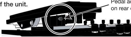
Pedal adjustment fitting is visible on rear of expression pedal 2.
2 Insert a 3mm size hex wrench into the fitting on the outside of the panel. To increase pedal firmness, turn the wrench clockwise. To decrease pedal firmness, turn the wrench counterclockwise.
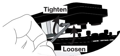
Adjusting vertical torque for expression pedal 1/2
1 Turn power to the G9.2tt off, disconnect the AC adapter from the unit, and turn the unit upside down.
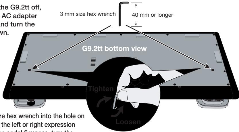
2 Insert a 3 mm size hex wrench into the hole on the underside of the left or right expression pedal. To increase pedal firmness, turn the wrench clockwise. To decrease pedal firmness, turn the wrench counterclockwise.

Warning
Expression pedal 2 of the G9.2tt is designed for operation with one foot. When the pedal is fully turned to the right, pushing it strongly down, hitting it, or otherwise exerting strong force on it will damage the pedal. Be sure to operate the pedal only within its designated range.
If you loosen the pedal too much, the internal screw may come off, and you will no longer be able to tighten the pedal. Perform this operation with care.
If the screw should have come off inside the unit, contact your dealer or an authorized Zoom service station.
Never try to open the cabinet of the G9.2tt yourself, and never turn power to the G9.2tt on if the screw is unsecured inside the unit. Otherwise the electronic circuitry may be seriously damaged.
© ZOOM Corporation
Reproduction of this document, in whole or in part, by any means, is prohibited.
G9.2tt Patch List
- When connected to a guitar amplifier, select the "For LIVE use" patches. When connected to a recorder or similar equipment, select the "For REC use" patches.
- Banks A and b of the preset area contain the same patches as banks U and u.
*The noise reduction setting may have to be adjusted according to the guitar and amplifier you are using.
The amp channel indicated by shading will be selected when the patch is called up.
The Z-pedal setting indicates the effect type name and the parameter name. Expression pedal 1 is always assigned to the Volume parameter.
DEMO *The 1 symbol indicates the vertical direction setting and the 2 symbol the horizontal direction setting.
*An effect listed in brackets () in the Z-pedal setting can be turned on by depressing the pedal fully.
| Patch name | PRE-AMP A | PRE-AMP B | FUNCTION1 | FUNCTION2 | Z-Pedal (Expression pedal 2) | |
| For LIVE use | For REC use | |||||
| G9 Drive | DZ Clean | PV Drive | A/B | Phaser on | Z-MonoPitch : PdIPosi V (+1 Oct) Z-MonoPitch : PdIPosi H (+2 Oct) | |
| U0 -1 | U0 -1 | This patch simulates the new-generation warming sound of Rage Against The Machine guitarist Tom Morello. Moving the Z-pedal in the vertical direction gives a 1-octave higher pitch change, and the horizontal direction adds one more octave, for extreme pitch changes. Channel A is modeled on the Diezel Herbert high-gain setting, and channel B on channel 1 clean sound of the Peavey 5150. | ||||
| CleanCMB | FD Clean | VX Clean | A/B | Hold Delay | ModernSpring : Mix AnalogDelay : Mix | |
| U0 -2 | U0 -2 | Ultimate clean tone recreating the saturation of a tube amp. Select either American Fender sound (channel A) or British Vox sound (channel B). By making use of the Energizer tube circuitry, the sound can be given additional sheen. | ||||
| CrosOver | Z Clean | OverDrive | A/B | BPM TAP | AMP-B : Gain Delay : Mix | |
| U0 -3 | U0 -3 | Versatile overdrive sound very popular in Fusion and Crossover of the nineteen-eighties. When playing a guitar solo, increase the gain by pushing down the Z-pedal. Add delay by moving the Z-Pedal sideways. Channel A offers Z Clean sound for cutting. | ||||
| X-Phase | FD Clean | VX Clean | A/B | Step on | X-Phaser : Rate X-Phaser : X-Fade | |
| U0 -4 | U0 -4 | Compression + phaser sound great for funky cutting. Cross-fade the regular phaser with the original sound by moving the Z-pedal sideways. Add brushing and single-note riffs to really build that groove. Channel A is a clean sound variation based on the Fender Twin Reverb. | ||||
| Wah&Pit! | MS #1959 | MS Drive | A/B | PdIMonoPitch on | PedalVox : Frequency PdIMonoPitch : PdIPosi | |
| U0 -5 | U0 -5 | This patch is ideal for some tricky guitar play. Use the Z-pedal with one foot and turn into Steve Vai. Control wah with vertical pedal movement and operate a mono pitch shifter in real time with horizontal pedal work. Channel A contains the Marshall 1959 crunch sound with moderate gain. | ||||
| Z-Talker | OFF | FuzzFace | A/B | DelayTAP | Z-Talking : Formant V Z-Talking : Formant H | |
| U1 -1 | U1 -1 | Make the guitar talk with the Z-pedal. Moving the pedal in a V-shaped pattern during chord stroking creates a back-up chorus. Or switch to channel B with the Fuzz Face sound for stronger impact. Channel A of the REC patch (u1-1) contains Z Clean sound. | ||||
| '70s Dry | TS+F_Cmb | SD+M_Stk | A/B | DelayTAP | P-Resonance : Frequency AnalogDelay : Mix | |
| U1 -2 | U1 -2 | Dry sound reminiscent of the seventies. Gradually moving the Z-pedal vertically brings up from the "woman tone" of Eric Clapton to brighter tone. Channel A is a combination of Fender combo amp and Ibanez TS-9 crunch sound. | ||||
| Morphing | Z Clean | MS Drive | A/B | P-Resonance on | ReverseDelay : Balance P-Resonance : Frequency | |
| U1 -3 | U1 -3 | Psychedelic morphing sound using reverse delay. Let the pedal take you from the real world (Arena) to the world of fantasy (Reverse Delay), and back again. Channel B gives a heavily distorted Marshall sound. | ||||
| HarmonyC | VX Clean | VX Crunch | A/B | DelayTAP Delay : Mix | H.P.S : Mix | |
| U1 -4 | U1 -4 | A patch that adds harmony in C major and delay to lead crunch sound. The Z-pedal lets you freely control the mixing ratio of delay and harmonized pitch shifter. Why not try your hand at guitar orchestration using delay tap and the Z-pedal. Channel A is a clean sound based on the same Vox AC30TBX. | ||||
| AcoJazz | Aco.Sim | FD Clean | A/B | Ensemble on Hall : Mix Delay : Mix | ||
| U1 -5 | U1 -5 | This patch uses the acoustic effect to modify the sound of an electric guitar in electroacoustic style. The beautiful ambience creates a Jazzy feel. Recommended for use with single-coil front pickups. Channel B provides the Fender Twin Reverb clean sound. | ||||
MODELING
| MS#1959 | MS #1959 | MS #1959 | A/B | Booster on | (Vibe : Rate) | Spring : Mix |
| U2-1 U2-1 | A patch modeled on the legendary Marshall 1959 SuperLead 100 used extensively by numerous rock guitarists. Enjoy distortion that is slightly different from modern high-gain stack amps. Pushing the Z-pedal all the way down turns vibrato on. Channel A is a variation of the same amp with lower gain setting. | |||||
| ENGL | ENGL Drv | ENGL Drv | A/B | Delay on | X-Wah : Frequency | X-Wah : X-Fade |
| U2-2 U2-2 | This patch simulates the sound of the ENGL E650 Ritchie Blackmore Signature 100. Ample distortion but never muddy, that is what Ritchie Blackmore's sound is all about. Moving the Z-pedal horizontally brings X-WAH into play. Channel A is a variation of the same amp with lower gain setting. | |||||
| Rectify | Rect CIn | Rect Vnt | A/B | Hall on | Hall : Mix | Chorus : Mix |
| U2-3 U2-3 | Simulates the high-gain sound of the Mesa Boogie Rectifier, a world-wide standard for heavy music. Warm sound with a strong presence provides a mighty buildup whether playing riffs or lead. Channel A provides the clean channel sound (Rect CIn). | |||||
| J-Chorus | JC Clean | JC Clean | A/B | ST-Chorus on | ST-Chorus : Mix | Hall : Mix |
| U2-4 U2-4 | A simulation of the Roland JazzChorus sound with its beautiful chorus-based clean tone. Every guitarist needs a transparent clean sound with a wide range of uses, for cutting, arpeggios and many other situations. Stereo chorus can be turned on and off with the function foot switch. Channel A offers a tone variation of the same JazzChorus. | |||||
| 800/2000 | MS Crunch | MS Drive | A/B | MultiWah on | (MultiWah : Frequency) | Hall : Mix |
| U2-5 U2-5 | This patch recreates both the Marshall JCM800 and JCM2000. Channel A is modeled on the characteristically solid crunch sound of the JCM800, while channel B brings you the higher gain sound of the JCM2000. Toggle between channels A and B with the function foot switch, for quick access to two types of Marshall sound. | |||||
| Diezel | DZ Clean | DZ Drive | A/B | AutoWah on | Z-MonoPitch : PdIPosi V (+1 Oct) | Z-MonoPitch : PdIPosi H (+1500 Cent) |
| U3-1 U3-1 | A simulation of the Diezel Herbert high gain sound popular among guitarists who want that extra heavy impact. Dry and penetrating distortion not available with other amps sharply etches the outlines also of a heavily down-tuned guitar. Channel A uses "DZ Clean" which simulates the Diezel Herbert channel 1 with ultra-clean, transparent tone. | |||||
MODELING
| Patch name | PRE-AMP CHANNEL A | PRE-AMP CHANNEL B | FUNCTION1 | FUNCTION2 | Z-Pedal (Expression pedal 2) | |
| For LIVE use | For REC use | |||||
| HiWatt | HW Clean | HW Clean | A/B | DelayTAP | Delay: Mix Chorus: Mix | |
| U3-2 | U3-2 | This patch is modeled on the clean tone of the Hiwatt Custom 100 with its lively midrange. The typical saturation characteristics of a tube amp are faithfully preserved, resulting in confident, responsive sound. Immerse yourself in the sultry clean tone of a British amp. Channel B is a tonal variation. | ||||
| AC30TBX | VX Clean | VX Crunch | A/B | Tremolo on Tremolo: Rate Tremolo: Depth | ||
| U3-3 | U3-3 | Simulation of the Vox AC30TBX crunch sound with the smooth high range typical of a class A amplifier, and its delicately detailed distortion. When you play a chord, the sound virtually jumps from the speaker in a way that is just not possible with other amps. Channel A gives the beautiful clean tone that is another hallmark of a class A amp. | ||||
| TriAmp | HK Clean | HK Drive | A/B | DelayTAP AnalogDelay: Mix AnalogDelay: Feedback | ||
| U3-4 | U3-4 | This patch simulates the smooth drive sound of the Hughes & Kettner Triamp MKII. Let the powerful low end and ample distortion propel your lead play. Channel A recreates the sound of the class A amp in the clean channel of the Triamp MKII. | ||||
| TweedDLX | US Blues | US Blues | A/B | BPM TAP E/Reflection: Mix TapeEcho: Mix | ||
| U3-5 | U3-5 | Sound modeled on the Fender Tweed Deluxe beloved by many Blues greats. Dry crunch sound with just the right amount of sustain brings out delicate shifts in dynamics that make all the difference. Lay your heart into those picking nuances. Channel B contains a Tweed Deluxe sound variation. | ||||
| Breaker | UK Blues | UK Blues | A/B | MultiWah on (MultiWah: Frequency) TiledRoom: Mix | ||
| U4-1 | U4-1 | The Marshall Bluesbreaker simulated by this patch is not an amp that provides heavy distortion like the Marshall JCM series. Its crunch sound faithfully follows each picking nuance and has the classic ring of British Blues in the vein of Eric Clapton. Channel B contains a variation with stronger drive feeling. | ||||
| W Fender | FD Clean | TweedBass | A/B | ST-Chorus on ST-Chorus: Mix ModernSpring: Mix | ||
| U4-2 | U4-2 | Channel A of this patch contains the clean sound of a Fender Twin Reverb, while channel B recreates the crunch sound of the Fender Bassman. With these two great choices, you can make optimum use of the stereo chorus while playing a wide variety of styles. | ||||
ARTIST
| Metallic | MS Crunch | DZ Drive | A/B | DelayTAP | PdIMonoPitch : PdIPosi | Echo : Mix |
| U4-3 | U4-3 | This patch simulates the Deep setting of the Diezel amp known for its hard, high-gain tone, used extensively by bands such as Metallica. It is best suited to playing guitar with drop tuning. Combination with Gate produces a dramatic and startling sound. Channel A is a Marshall crunch sound. | ||||
| BlackMor | MS #1959 | ENGL Drv | A/B | Booster on | Ensemble : Mix | Echo : Mix |
| U4-4 | U4-4 | Simulation of the famous Ritchie Blackmore sound. Channel A emulates the Marshall 1959 and channel B the ENGL Drv setting for Deep Purple and Rainbow sound, respectively. Press function foot switch 2 to turn the booster on and get that great tone for lead play. | ||||
| SurfRock | FD Clean | dist+ | A/B | BendChorus on | X-Vibe : TRM Rate | X-Vibe : X-Fade |
| U4-5 | U4-5 | The ideal sound for playing surf rock in the style of The Shadows or The Ventures. Get those phrases flowing and catch the wave. Move the Z-pedal sideways to use both phaser and tremolo. Channel B is a dry sound using modeling of dist+. | ||||
| Smash | Rect Mdn | DZ Drive | A/B | Delay on | (Delay : Mix) | Room : Mix |
| U5-1 | U5-1 | Simulates the punk rock sound pumped out by Offspring. The drive feeling will make you want to hit those power chords, but the sound still retains enough crispness for speedy playing. Channel B notches up the aggressiveness with DZ Drive. | ||||
| The Edge | HW Clean | BigMuff | A/B | BPM TAP | ST-Chorus : Mix | Echo : Mix |
| U5-2 | U5-2 | Simulates the sound of the famous U2 guitarist Edge who jumped onto the world scene in the 1980s. Moving the Z-pedal sideways produces clear echo sound. Make optimum use of the pedal for those impressive solos. Channel B offers BigMuff type fuzz sound. | ||||
| NotSubtl | Z Clean | DZ Drive | A/B | RingModulate on | RingModulate : Frequency | AnalogDelay : Mix |
| U5-3 | U5-3 | Simulates the loud and super-distorted sound of Slipknot, a major band on the modern heavy music scene. Moving the Z-pedal vertically gives the sound a more metallic ring, while the horizontal direction adds ambience for solos. Channel A provides Z Clean sound. | ||||
| SalasWah | Z Clean | Guv'nor | A/B | AutoWah on | AutoWah : Resonance | Room : Mix |
| U5-4 | U5-4 | This patch simulates the heavy auto wah sound of Stevie Salas. It uses the compressor + auto wah combination indispensable for true funk. Make free use of brushing and single-note cutting to play those groovy phrases. Channel A contains a clean sound. | ||||
| BeckOct | FD Clean | RAT | A/B | DelayTAP | Octave : OctLevel | Echo : Mix |
| U5-5 | U5-5 | Simulates the octave sound cherished by Jeff Beck. It's the ideal patch for playing passages in the fluid driving style of his famous song "Led Boots". Adjust the octave level with the pedal. Channel A provides a Fender Twin Reverb clean sound. | ||||
| KingTone | FD Clean | UK Blues | A/B | DelayTAP | Echo : Mix | ModernSpring : Mix |
| U6-1 | U6-1 | Clean tone like the choking guitar of the king of Blues, Mr. BB King. Recreate the moody solo from "The Thrill Is Gone", and use the pedal to control the ambience. Channel B has a drive sound modeled on the Marshall Bluesbreaker. | ||||
ARTIST
The amp channel indicated by shading will be selected when the patch is called up.
*The Z-pedal setting indicates the effect type name and the parameter name. Expression pedal 1 is always assigned to the Volume parameter.
The symbol indicates the vertical direction setting and the v symbol the horizontal direction setting.
*An effect listed in brackets () in the Z-pedal setting can be turned on by depressing the pedal fully.
| Patch name | PRE-AMP CHANNEL A | PRE-AMP CHANNEL B | FUNCTION1 | FUNCTION2 | Z-Pedal (Expression pedal 2) | |
| For LIVE use | For REC use | |||||
| Hendrix | MS Crunch | FuzzFace | A/B | Phaser on | Vibe : Rate Hall : Mix | |
| U6-2 | U6-2 | The wild and mighty fuzz sound of guitar god Jimi Hendrix. Push the pedal down and be transported to Woodstock in 1969. Shake the earth with your thundering riffs. Channel A of the REC patch(u6-2) simulates the Marshall 1959 sound. | ||||
| Cream | Z Clean | UK Blues | A/B | DelayTAP | AutoPan : Rate Echo : Mix | |
| U6-3 | U6-3 | The Cream hit "Badge" which they also played at their reunion concert is driven by its beautiful melody and an enchanting combination of crunch and rotary speaker sound. That is the sound contained in this patch. By assigning multiple effects to the pedal, even the speed control of the rotary speaker is convincingly reproduced. Channel A is a clean sound variation. | ||||
| ZZ Drive | FZ+M_stk | FZ+M_stk | A/B | BPM TAP Delay : Mix Chorus : Mix | ||
| U6-4 | U6-4 | Simulates the special drive sound of Billy Gibbons who gained fame as the guitarist of ZZ Top. When you push the Z-pedal hard, delay is added, and horizontal movement adds chorus. Hold your guitar way down low and start the hard boogie. Channel B is high-gain variation. | ||||
| SRV | FD Clean | TS+F_Cmb | A/B | Wah on Vibe : Balance Vibe : Rate | ||
| U6-5 | U6-5 | This patch is modeled on the definitive clean tone of Stevie Ray Vaughan. Great for fast chord cutting and dynamic stroking. Use heavy-gauge strings to play some Texas Blues. Channel B contains TS+F_Cmb drive sound. | ||||
| SatchDST | DS-1 | MS Drive | A/B | Delay on CombFilter : Frequency Delay : Mix | ||
| U7-1 | U7-1 | Simulates the lead tone of super guitarist Joe Satriani. The sound of the orange Boss DS-1, the quintessential distortion pedal, is a good match for phrases that require real mastery of technique. Channel B features high-gain Marshall sound. | ||||
| LukeCLN | Z Clean | Rect Vnt | A/B | DelayTAP Delay : Mix ST-Chorus : Mix | ||
| U7-2 | U7-2 | Steve Lukather is largely responsible for the sophisticated sound of Toto that swept the world. In the eighties, he was using the clean tone that is simulated by this patch. Channel B will let you produce the flashy lead sound of the Mesa Boogie Rectifier. Classic rock'n roll has never sounded better. | ||||
| Santana | BG Crunch | BG Crunch | A/B | Arena on (PedalVox : Frequency) AMP : Gain | ||
| U7-3 | U7-3 | The Santana sound is perennially popular among rock fans the world over, but the band also often collaborated with major Jazz artists. That sweet and drawn out Santana lead tone is simulated by this patch. Choke your guitar at the upper end and immerse yourself in "Europe". Channel A contains a variation with reduced drive. | ||||
| B.Setzer | TweedBass | TweedBass | A/B | PRE-AMP on ModernSpring : Mix Echo : Mix | ||
| U7-4 | U7-4 | This patch simulates the Rockabilly sound of Brian Setzer who became instantly famous for his "Dirty Boogie" album. The quality feel of the sound will have you swinging in a heartbeat. The TweedBass setting in channel A has reduced gain and a less pronounced tone. | ||||
| BrianDly | VX Crunch | ENGL Drv | A/B | Hold Delay PingPongDly : Mix H.P.S : Mix | ||
| U7-5 | U7-5 | Simulates the sound of guitar magician Brian May who created the dramatic allure of Queen. Use the Z-pedal to blend the alternating right/left delay with the harmonized pitch shifter to weave some guitar magic. Channel A is a Vox crunch sound suitable for backing. Channel B of the REC patch (u7-5) provides PV Drive sound. | ||||
| KurtDRV | Z Clean | BigMuff | A/B | Ensemble on AMP-B : Gain Ensemble : Mix | ||
| U8-1 | U8-1 | In the nineties, Kurt Cobain of Nirvana changed the music scene forever, with his grunge sound making dramatic use of distortion and modulation. This patch will make you want to play those riffs from "Smells Like Teen Spirit". Channel A recreates the clean sound for the intro. | ||||
SPECIAL FX
| X-Flange | Z Clean | HotBox | A/B | X-Flanger on | X-Flanger : Rate | X-Flanger : X-Fade |
| U8-2 | U8-2 | This flanger based jet sound is the signature sound of hard rock. Move the Z-pedal in the horizontal direction to adjust the flanger amount. The REC patch (u8-2) gives you two fighter planes that cross the stage from right and left when you move the Z-pedal horizontally. Channel A is a clean sound suitable for arpeggios. | ||||
| PedalPan | FD Clean | DZ Drive | A/B | Z-Echo on | X-Dimension : Depth | X-Dimension : Pan |
| U8-3 | U8-3 | This patch lets you move the effect sound with the Z-pedal, to create an intriguing space effect. In addition, Z-Echo gives you a time stretch that resembles analog delay. Channel A is a high-gain sound modeled on the Diezel Herbert channel 3. | ||||
| Rotary | Z Clean | UK Blues | A/B | DelayTAP | AutoPan : Rate | AnalogDelay : Mix |
| U8-4 | U8-4 | Spectacular rotary speaker simulation using three types of modulation. Use function foot switch 1 to change from the drive sound of channel B modeled on the Marshall Bluesbreaker amp to the Z Clean sound. The vertical direction of the Z-pedal controls the rotation speed, and movement in the horizontal direction adds delay. | ||||
| PdlPhase | HW Clean | TS808 | A/B | BPM TAP | FixedPhaser : Frequency | Echo : Mix |
| U8-5 | U8-5 | This patch produces utterly clean, transparent sound. The Z-pedal allows versatile control of the phaser sound and echo sound. Channel B contains drive sound modeled on the TS808. | ||||
| Gt-Osc | TweedBass | HotBox | A/B | Delay on | Z-Oscillator : Balance | Z-Oscillator : Portament |
| U9-1 | U9-1 | This patch produces an enigmatic sound that uses the oscillator effect. The Z-pedal lets you choose between guitar sound and synthesizer sound. Channel A is a crunch sound modeled on the Fender Bassman. | ||||
| Bend4T | Z Clean | JC Clean | A/B | BPM TAP | BendChorus : Balance | Hall : Mix |
| U9-2 | U9-2 | Clean sound featuring ZOOM's traditional bend chorus. Play a solo with a Pop style bend, a great match for bands with alluring female vocals. Channel B is a clean sound variation using JazzChorus. In the REC patch (u9-2), Z-Delay is assigned to the pedal, allowing you to change the position of the delay sound only. | ||||
SPECIAL FX
| Patch name | PRE-AMP CHANNEL A | PRE-AMP CHANNEL B | FUNCTION1 | FUNCTION2 | Z-Pedal (Expression pedal 2) | |
| For LIVE use | For REC use | |||||
| SFX G9 | FD Clean | BigMuff | A/B | BPM TAP | Z-Step : Frequency Z-Step : Mix | |
| U9-3 | U9-3 | This patch produces a sound like bubbles forming under water. By moving the Z-pedal, you can make the bubbles burst. When listening with headphones, you'll feel immersed in a liquid universe. As the name "SFX G9" indicates, this kind of sound is possible with the G9 only. Every guitarist is sure to find new inspiration here. Channel B contains dramatic BigMuff type fuzz sound. | ||||
| Pdl-Osc | Rect Vnt | Rect Vnt | A/B | DelayTAP | Z-Oscillator : Frequency Z-Oscillator : Balance | |
| U9-4 | U9-4 | This Theremin style sound using the Z-Oscillator is generated when you move the Z-pedal. Expect to be amazed by a sound that goes far beyond what guitar effects normally offer. Added reverb and delay help to create a fantastic world. | ||||
| RingMod | FD Clean | DZ Crunch | A/B | Z-Echo on | RingModulate : Balance RingModulate : Frequency | |
| U9-5 | U9-5 | Drive sound using the ring modulator. Moving the Z-pedal alters the Z-Echo Time parameter and the RingModulate Frequency parameter assigned to the pedal, resulting in a spacy sound. Channel A contains a Fender Twin Reverb clean sound. | ||||
Recommended Accelerator settings
Normal Clean
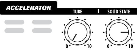
Settings for clean tone with low distortion levels
Tube Pre-amp
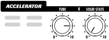
Settings for adding tube compression
Clean-Tube Mix
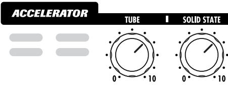
Settings for mixing solid state clean sound and tube distortion
Recommended settings for major guitar amps
Marshall JCM-2000
Live performance patches (U0~U9, A0~A9)
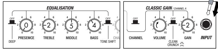
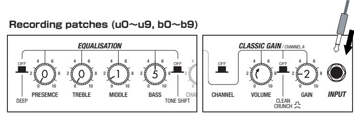
Fender Twin Reverb
Live performance patches (U0~U9, A0 ~A9)
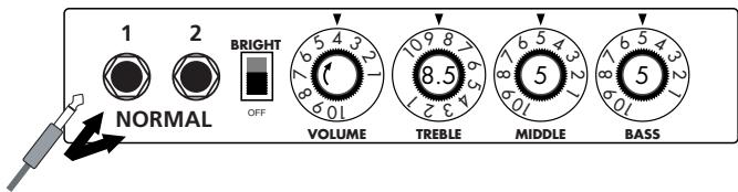
Recording patches (u0~u9, b0~b9)
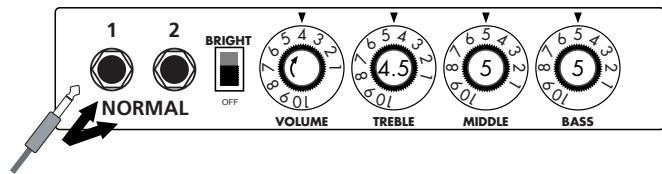
Roland JC-120
Live performance patches (U0~U9, A0~A9)

Recording patches (u0~u9, b0~b9)
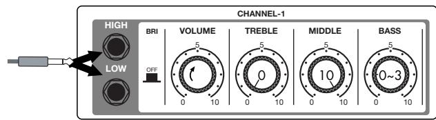
- The recommended settings shown above are for the FRONT setting of the amp select feature.
- If a recording patch is selected while using a guitar amp, the desired effect may not be obtained and the sound may be unpleasant. Adjust the amp settings using the above examples as reference.
- The recommended settings shown above may need fine-tuning according to usage condition of the amplifier.

Fender Twin Reverb '65
FD Clean
Fender Tweed Deluxe '53
US Blues
In the later half of 1963, a reverb unit was added to the "Twin" amp, which was the birth of the "Twin Reverb" model. In 1965, Fender company was sold to CBS because of Leo Fender's health problem. The program on this Zoom G series is modeled after the pre-CBS "Twin Reverb" from 1965 aka "Black Panel". This amp has four 7025 (12AX7), a 12AX7 and two 12AT7 pre-tubes, four 6L6GC power-tubes and silicon diodes for the rectifier circuit. The diode rectifier is believed to give a tighter sound to the amplifier than the tube rectifier does, which should be the key to the characteristic glittering sound of this "Twin Reverb". This guitar amplifier has two 12" loudspeakers by Jensen and pus out 80w power. On the program in this Zoom G series, you can have the sound with the "Bright" switch on by tweaking the "Harmonics" parameter in the "6 band EQ" section. When you turn the reverb effect on, you will get that "Twin Reverb" sound you have been longing for.
The very first Fender amplifier was developed by Leo Fender and his trusty partner, the engineer Doc Kaufman in 1945-46. Actually, the earliest models were not made under the "Fender" brand but the "K&F Manufacturing Corporation" named after the Initials of the two. The first amplifier using the "Fender" brand was the "Model 26" in 1947. In 1949, the entry models called "Champion 400/600" series followed. The so-called "Tweed Amps" covered literally with tweeds all over were developed during the 1950s and the 1960s. In these years, the company put out various tweed models like the "Bassman" or the "Bandmaster". The program of this Zoom G series is modeled after, among others, the most representative "Tweed Deluxe" aka the "Wide Panel" from 1953. This amplifier has a 12AY7 and a 12AX7 pre-tubes, two 6V6GT power-tubes, a 5Y3GT rectifier tube and a 12" Jensen loudspeaker and its output power is 10w. Recently the original amplifier is priced quite highly and is very difficult to find in good condition. This amp has two inputs but one is the input for a microphone. It has just one tone knob for treble control. Therefore, it is advisable to use this program on the Zoom G series with a flat tone setting except for the treble parameter so that you can enjoy the characteristic sound in the lower registers and the unique sound in the higher registers of the original Fender amp.

Marshall 1959 SuperLead100
MS#1959
This 1959 stack amp that received the nickname "Plexi" from the material of its front panel is one of the most famous amplifiers in Rock history. Its iconic status is right up there with the Fender Stratocaster and the Gibson Les Paul. Jimi Hendrix, Jimmy Page, Edward Van Halen, Eric Clapton and many other top guitarists all over the world have immortalized its sound in countless recordings. It is no exaggeration to say that virtually everybody has heard the sound of this amp at least once. By way of circuitry, it uses three ECC83 preamp tubes and four EL34 power tubes. Two cabinets with four Celestion 12" speakers complete the package that is the epitome of British Rock. With the volume full up, the aggressive transients and distortion sound complemented by smooth harmonics are the dream of every guitarist. The only drawback could be seen in the fact that a very high volume level is needed to get that sound. But the Zoom G9.2tt overcomes this problem, letting you duplicate the sound by simply raising the gain parameter. After all, even Rock guitarists should be kind to their ears.
Marshall 1962 Bluesbreaker
Since it was used by Eric Clapton when recording the album "John Mayall and the Blues Breakers with Eric Clapton" (commonly known as the "Beano" album), this amp has acquired the moniker "Bluesbreaker". Up to then, guitar amps aimed for a clean sound with minimal distortion, but the fat and sweet tone of this amp driven by Eric Clapton's Les Paul fascinated guitarists the world over. They liked it so much that it has become the defining sound of the rock guitar. While different from the distortion produced by modern high-gain amps, the long sustain and distortion following each picking nuance is ideal for playing the blues.
The creamy sound of this amplifier with its four ECC83 pre-stage tubes, two 5881 power tubes, and a GZ34 tube in the rectifier circuit is perfectly captured by the simulation.

Roland JAZZ CHORUS
JC Clean
Simply put, the Roland "JC-120" is the most familiar guitar amplifier among both professionals and amateurs. Released in 1975 from Roland, this amp became known as "portable", "loud" and "almost trouble-free" (which are the very characteristics Japanese products are known for!). You are pretty sure to find one in any live houses or studios all over the world. The key to that sound of "JC-120" is its unique chorus effect: the slightly delayed vibrato sound comes from one of two 12^ loudspeakers and the dry sound from another and both sounds are combined in the air, which creates that distinctive spacey mood. This effect became very popular which is why Roland decided to release the chorus circuit independently as the "CE-1" pedal. Incidentally, the chorus effect on the Zoom G series is modeled after its follower "CE-2". Another unique feature of JC-120 is its "Bright" switch. This function is not included in this modeling program but you can approximate the effect of this switch by tweaking the "Harmonics" parameter in the "6 band EQ" section.
HIWATT Custom 100
The Custom 100 was the flagship amp from Hiwatt, a British manufacturer that ranks with Marshall among the British legends. Vintage Hiwatt amplifiers made before the mid-1980s use high-grade military-spec parts and hand-soldered point-to-point wiring. This is the reason why production was limited to about 40 units per month. Because of their solid construction, these amplifiers have been likened to tanks. Their sound, in a word, is the epitome of clean. The pre-stage tubes are ECC83, while the power tubes are the same EL34 as used by Marshall. Unlike the glittering clean sound of a Fender amp, the clean sound of a Hiwatt is darker, having that characteristic British tone. Especially in the "normal" channel, turning up the volume to maximum will simply increase the sound pressure, without breakup or loss of detail. In the high-gain "brilliant" channel, slight distortion is possible by connecting a guitar with a high-output pickup such as a Les Paul. But the sound always remains detailed and transparent, allowing the listener to clearly pick out the individual notes that make up a chord. The "normal" and "brilliant" channel inputs can be linked with a short shielded cable, for even higher sound pressure output.
This effect type simulates the linked sound as described above, much favored by Pete Townshend of The Who and Pink Floyd's David Gilmour.

ENGL E650 Ritchie Blackmore Signature 100
ENGL Drv
The German-born ENGL started out as a tube combo amp built in the mid-eighties by Edmund Engl. Towards the end of that decade, Heavy Metal ruled the music scene and high-gain amps were in great demand. ENGL rose to the challenge with a full-blown stack amp that caught the attention of professional musicians in Europe and cemented the reputation of the brand. The head amp E650 uses three ECC83 tubes in the pre section and four 5881 (6L6GC) tubes in the power section. It has two channels (Clean/Lead), but since it allows overall Lo/Hi gain switching, the amp can also be regarded as a four-channel unit. The Clean channel provides a tight, bright Fender style clean sound that is unusual in a stack amp. The Lead channel is more in the Marshall vein, but at higher gain settings, it becomes a unique ENGL sound. But another vital aspect of the ENGL sound is the solid and heavy E412VS cabinet with its 4 × 12 " Celestion Vintage 30 speakers. The Zoom G9.2tt simulates the Lead channel of the E650 combined with the E412VS.
PEAVEY 5150 STACK
The "5150" and the "5150 MkII" were very famous guitar amplifiers originally developed as the signature models for Eddie Van Halen. Unfortunately, he doesn't use it anymore because of the expiration of the endorsement contract. The program on this Zoom G series is modeled after the first version of the "5150". This amplifier has two (Rhythm and Lead) channels and puts out 120w power using five 12AX7 pre-tubes and four 6L6GC power-tubes. The rectifier circuit employs silicon diodes. The uniqueness of the sound of this amplifier is characterized by its sharp attack, deep and smooth tone, fine distortion and fat and clinging low registers. The program is modeled after the combination of the Lead channel of the 5150 head and a "5150SL", a four-12" cabinet. Just crank up the gain and play one of Van Halen's hit "Top Of The World!"
UK Blues
Fender BASSMAN
Among the many famous Fender amps, the Bassman has earned a special place. When Jim Marshall developed his original amplifier, he is said to have used the Bassman circuit as a reference. When it first came out in 1951, the Bassman had an output of 26 watts and used a single Jensen 15-inch speaker. After various modifications, it reemerged in 1959 with a 50-watt output and four Jensen 10-inch drivers. The simulation of the Zoom G series is modeled on the "bright" channel of the '59 Bassman. Introduced at the 1951 NAMM show along with the Precision Bass, this amp was originally intended for use with bass guitars. But its reedy distortion made it a favorite with some of the early blues giants, and later with many rock guitarists. Of course, the amp continues to be used by musicians to this day.

TweedBass
VoxAC30TBX
Tracing back the long history of Vox, one finds that it all began in 1958 under the moniker "Jennings Musical Instruments" (JMI). Originally, this company built amps in the ten to fifteen watt range, but as time went on, the demand for higher-power amps became stronger, leading to the birth of the famous AC30. The original AC30 had two Alnico Celestion 12" speakers, an EF86 tube preamp and EL84 tube power section, along with a GZ34 rectifier. Around this time, the Shadows as well as the Beatles started using the AC30 which quickly became very popular among guitarists. In the following years, musicians wanted even higher gain, and Vox responded with the Top Boost unit, an add-on that was later integrated in the AC30TBX. This is the model whose sound is simulated by the Zoom G series. After Vox left the JMI stable, sales unfortunately dropped drastically. In recent years, Korg has acquired the trademark rights to the Vox name and has started to produce a reissue that is faithful to the original sound. The AC30TBX simulation in the Zoom G9.2tt duplicates the Hi gain inputs of the normal channel and brilliant channel. It delivers a clean unsullied sound typical of a class A amplifier as well as smooth overdrive sound.
MS Crunch
Marshall JCM2000
Marshall has continued to produce great amplifiers for up-to-date musical trends in cooperation with the musicians. This brand started with its "JTM- 45 (stands for Jim&Terry Marshall)" in 1962 and now its products are indispensable items in the modern Rock scene. Marshall seems to have been experimenting with different circuit designs of amplifiers but 1981 was the most prolific year for the brand because it released many new models like the "1959" and "1987" with four inputs, "2203" and "2204" with master volumes. In 1983, Marshall added the "2210" and "2205" with two (Normal and Boost) channels as well as effect send/return connectors to its lineup. These models also carried the collective designation "JCM (stands for Jim&Charles Marshall) 800". They had three ECC83 pre-tubes and four EL34 power-tubes. The tone control circuit was placed after the pre-amp section and this design seems to have become the standard for the modern Marshall amplifiers. For the modeling on this Zoom G series, we selected the "2203" with a master volume and it is quite easy to get the distortion. By today's standards, the amplifier's distortion is rather moderate, but the sound is very fat, the low-end is quite tight and, above all, the sound cuts through very well. For the modeling, we used the head with a "1960A" cabinet that has four 12" loudspeakers and works very well with the "2203".
"JCM2000" is based on the reputed "Plexi" amp (aka Old Marshall) whose rich overtones and powerful sound were legendary. It has very flexible sound and can produce the traditional Marshall sound, modern heavy metal sound or sounds suitable for any musical genre. It has the modern Marshall's standard circuit with four ECC83 pre-tubes and four EL34 power-tubes. It is an all-tube amplifier that can produce clean or heavily distorted sound and you can use it in all kinds of music. The sound is rather grainy but the response is fast and the guitar sound cuts through very well. "JCM2000" series has two different models: the TSL and the DSL. The program on the Zoom G series is modeled after the simply designed "DSL-100". As with the modeling of the "JCM800", we combined the head with a "1960A" cabinet and used the Lead channel that has more distortion.
BG Crunch
MESA/BOOGIE Dual Rectifier
The origin of the MESA/BOOGIE amplifier was the modified Fender Princeton. Randall Smith, an amp tech in San Francisco, souped up those small guitar amps to put out 100w power and sold them. The first model was called "Mark I". Carlos Santana tried one and said, "Shit man, that little thing really Boogie! -which gave the amplifier the brand name "BOOGIE." The second model "Mark II" had lead and rhythm channels and a 4-band equalizer to give wider variety to the guitar tone. The special feature of this model was an accomplished simul- power circuitry (the operation could be switched between class A and class AB). The power amplifier section had six power tubes. When the class A operation is selected, two EL34 power tubes are activated and the amp puts out a really smooth sound. When the class AB operation is selected, these two EL34s and other four 6L6GC power tubes are all activated and the amplifier puts out its full potential power.
Until the model Mark II, MESA/BOOGIE amps were quite expensive, hand-made amplifiers, but the next model "Mark III" was more affordable. It has one 10^ loudspeaker and 60w output power but retains all of the classic BOOGIE features; simul-power circuitry, the graphic EQ, and three (Rhythm1, Rhythm2 and Lead) separate channels. With this Zoom G series, you can select the modeling of the combo type of this "Mark III."
The Rectifier was born by improving on the simul power circuit of the Mesa/Boogie Mark 1 to 3 as well as increasing the preamp gain and applying other tweaks. From its five 12AX7 preamp tubes and four 6L6GC power tubes, the amp produces an output of 100 watts. Unlike the Mark series, this model gives priority to tone, featuring a tone control circuit after the volume. With this model, the Mesa/Boogie brand image progressed from Fusion to Metal. The distinguishing feature of this amplifier, and its namesake, is of course the rectifier. The sound provided by this patch is based on the Dual Rectifier model which has two rectifier circuits, one of which is tube based and one configured with silicone diodes. The diodes create a tight, high-powered sound, while the tube sound is more soft and warm. The Zoom G9.2tt simulates the orange channel with its characteristic warmth, and the high-gain red channel having vintage and modern modes. Both use the silicone diode rectifier, and the cabinet is the same as the Boogie with four Celestion 12" speakers.
HK Clean
HK Crunch
HK Drive
Diezel Herbert
O Hughes & Kettner TriAmp MK2
Using a total of 13 tubes in the pre and power amp stages, with A and B settings for each, this is a monster of an amplifier offering the equivalent of six channels to play with. AMP1 is a Fender type clean channel with bright and uncluttered sound. AMP2 is a classic British drive channel which covers the overdrive range from crunch to distortion. AMP2 has already fairly high gain, but it is surpassed by AMP3. While allowing deep distortion, the sound has a solid core and remains wonderfully detailed. The reason why the TriAmp is so popular among guitar pros is the fact that all three channels offer high-quality sound. The full range from clean to high-gain distortion can be covered with a single amp. The Zoom G9.2tt simulates all three channels, letting you enjoy the same versatility as the monster amp itself.
Diezel Herbert
This modern three-channel amp features great tonal versatility, ranging from clean tone to distortion. In particular, the extremely dry anditty distortion produced by channel 3 gives a piercing effect that is hard to produce with any other amp. It is a favorite of Heavy Rock bands such as Metallica and Limp Bizkit. The uncluttered sound sharply etches the outlines also of a heavily down-tuned guitar. A DEEP control allows further boosting of the bass frequencies, for sound so low that it seems to hug the ground. The Zoom G9.2tt lets you achieve the same effect by boosting the BASS control of the EQ module. While the amp is justly famous for its distortion sound, the other channels also provide attractive choices. Channel 1 is ultra-clean, and channel 2 has a dry crunch sound with a character that clearly distinguishes it from Californian amps. The Zoom G9.2tt provides patches modeled on all three channels.
VX Clean
VX Crunch
he moniker
the ten to
the ten to
ps became .
pE
two Alhico
ong with a
the AC30
g the AC30
musicians
in that was.
it that was
he Zoom G .
eont years .
recent years,
duce a re-
com 6037
Joan G9.21t
vers a clean .
MS Drive
MS DRIVE
n overtones
reduce the
Duce the
any musical
es and four .
and four
ly distorted .
the response .
no response
no different
r the simply
e head with
- head with
Rect Cln
Rect Vnt
Rect Mdn
m - 1 0 ;
G9.2tt Modeling Description ② Reference for drive effect types and its original models.
BOSS OD-1
OverDrive
The "OD-1" released by BOSS in 1977 was originally developed for the simulation of the natural overdrive sound of tube amplifiers, but this stomp box turned out to be popular as the booster unit to connect to the input of the real tube amplifier to get tighter and more punchy sound with the increased gain. The "OD-1" employs the asymmetrical "clipper" section in its circuit design that uses three diodes to create the overdrive sound that is mild and rich in nuances. The pedal had been in production from 1977 to 1985, but now it is unexpectedly difficult to even find a used one. And if you could locate one, it would be astonishingly expensive. There have been many stomp boxes known as overdrive units. The most famous one is probably the "Tube Screamer" but we chose this very original overdrive pedal "OD-1". If you are lucky enough to use the real "OD-1", we invite you to try blind test to turn off all of the effect module except the "OD-1" on the Zoom G series and compare the sound of the modeling and that of the real one. We think that you will not hear any difference.
Obanez TS808
This is modeled on the early Tube Screamer introduced by Ibanez in 1979 for the non-US market. In Japan, it was sold under the Maxon name as the OD808. As the moniker implies, when using the pedal on its own, it produces natural distortion such as when driving a tube amp hard. But it often was used simply as a booster, with gain at 0 and volume at 10, to drive a full-up amp even further. Normally, this would not change the amplifier's sound, but a slight peak in the midrange results in a softer tone.
This pedal is also famous for being used by blues guitar legend Stevie Ray Vaughan who tragically perished in a helicopter crash.
TS808
Centaur
KLON CENTAUR
This pedal is well known for two things: its capability of producing pure distortion without impairing the original sound, and its high price. Being four-and-a-half years in the making, the Centaur distinguishes itself from other famous pedals such as the Ibanez TS808 or the Boss OD-1. It is also often used as a booster, but whereas these vintage pedals add their characteristics to the amp sound, the Centaur creates a tone as if it were driven by the amp.
Marshall Guv'nor
The initial sales talk for this serious distortion pedal "Guv'nor" bearing the Marshall brand was that you could get the distortion sound of the Marshall amps with this small stomp box. Depending on which guitar amps you combine, you can actually get the Marshall amps distortion. There are two different versions of the Guv'nor: the Britain-made ones from 1988 and the Korean-made ones from 1998. The program on this Zoom G series is modeled after the original version from 1988. The Guv'nor's characteristic feature is the frequency point you can tweak using the "TREBLE" control. Even if you lower this parameter value, the sound will get fat instead of getting dullish. As you raise the value, the sound will get sweeter and clearer.
O PROCO RAT
RAT
This is one of the most widely used pedals. It has only three knobs (Distortion, Filter, Volume), but each knob has a wide adjustment range, allowing various types of sound. With distortion fully turned up, the fat, up-front sound is close to a Fuzz pedal. At the twelve o'clock position, the crunch sound brings out those fine picking nuances, allowing the player to tweak the sound by varying the playing style. As opposed to a regular tone control, the filter knob cuts the treble when turned clockwise. This is the secret behind the typical "RAT" sound. In the Zoom G series, this effect is simulated by the TONE parameter, but operation is reversed (treble is cut when turned counterclockwise).
BOSS DS-1
This orange-colored pedal can be called the standard of distortion sound. Among the many distortion pedals from Boss, it is a real long-seller, along with the SD-1. In Japan, sales of the pedal ceased at one point (although production for the U.S. market continued), but as of 2005, the product is available again. This is the only Boss pedal to be reintroduced to the market in this fashion. The sound is trebly and very "distortion-like", but it can very well hold its own in a band. Favored by Joe Satriani and Nirvana's Kurt Cobain.
DS-1
C
MXR Distortion+
MXR, a company founded in the seventies by two high school students, is famous for stomp boxes such as the Dynacomp and Phase 90. In the early days, their products were actually built and painted in a garage and set out to dry in the garden. As the story goes, sometimes small insects would get stuck on the surface, and the lot would be shipped out as is. The pedals soon gained worldwide fame in the seventies, but eventually lost their market share to "Made in Japan" products from Boss and others that provided high performance at lower cost. MXR disappeared from the scene, but in the late eighties, Jim Dunlop bought the rights and is now producing a number of re-issue models.
This pedal much beloved by Randy Rhoads who made the "distortion" moniker and sound famous the world over. The hard-edged tone stays detailed also when playing fast solos or riffs with the lower strings muted. The world of heavy metal and hard rock wouldn't be the same without it.
Guv'nor
HotBox
MATCHLESS HOT BOX
The "HOT BOX" was released as a pedal preamp bearing the MATCHLESS brand. It uses two 12AX7A tubes for the truthful reproduction of the sound of the "MATCHLESS" guitar amplifiers. It has the compressed sound and the quick response, which are distinctive characteristics of tube amps. Its sound is fat and cuts through very well, too. Even if you crank up the gain to get a distorted sound, you will retain the nuances of the original guitar sound. Although it is categorized as preamp, the ideal way to get the best possible sound is to connect it, like usual stomp boxes, to the input of your guitar amp. Its design is also attractive: the case is polished like a mirror and the "MATCHLESS" logo lights up when you turn it on. This "Hot Box" is literally a magic box: you can get the signature sound of the "MATCHLESS" amps regardless of the guitar amplifier you connect it to.
0
Dallas-Arbiter FUZZ FACE
FuzzFace
"FUZZ FACE" was originally released from the Dallas-Arbiter company in 1966 encased in a uniquely designed housing that literally looked like a face. It is also famous as legendary guitarist Jimi Hendrix's favorite gear. He combined this "FUZZ FACE" with his Marshall amps because it was hard to get distorted sound from them at that time, and created avant-garde tones. The heavy and fat low end and the fuzz sound with long sustain are the characteristics of this effective device. The earliest model used two PNP germanium transistors and was very different in sound from the later models using silicon transistors. The theory of creating distorted sound is simple. Have you tried to connect the guitar to a microphone input on your radio cassette recorder to emulate that sound? You cannot go too wrong if you think that the circuitry of this device is similar to that. The program on this Zoom G series is modeled after this earliest version most satisfactorily.
Electro-Harmonix BIG MUFF
There are several versions of this pedal. The Zoom G series simulation is based on the so-called "Ram's Head" from the early seventies, characterized by very long sustain and rich distortion tapestry. Major names from the 70's associated with this sound are Carlos Santana and Robert Fripp of King Crimson. From the late eighties into the nineties, the grunge movement took over, with Nirvana's Cobain and J. Mascis of Dinosaur Jr. using the pedal to do their thing. Compared to an ordinary fuzz pedal, the BIG MUFF offers rich midrange and detailed distortion that maintain presence also when playing chords. The result is a wholly unique sound somewhere between distortion and fuzz.
BigMuff
MetalZone
BOSS MT-2
The "MT-2" ("METAL ZONE") has the strongest distortion. Its unique distortion sound has very fat mid to low range and it has a parametric EQ in addition to the Hi and Low EQs, which is the key to the scooped metal sound. This stomp box is reputed for its flexibility in sound because you can not only get that scooped metal sound by cutting the mid range and boosting the high and low range but also the overdrive sound by reducing the gain and boosting the mid range. This is one of the best-selling stomp boxes among many of the popular line-ups of BOSS products. Once connected, the Strat or the Les Paul will have the "MT-2" sound regardless of the types of guitar pickups. It was first introduced in 1991 and is still in the BOSS's catalog; a truly a long-seller!
TS+F_Cmb
Fender Combo + TS9
Opinion may be divided, but it can be argued that the most powerful and fat guitar sound ever was created by Stevie Ray Vaughan. He did this by putting extremely heavy-gauge strings that would fit an acoustic guitar on his old and battered Stratocaster. Add to this the full-up Fender amp and a small Ibanez pedal, and you are approaching magic territory. Just like this effect type does. Connect a Stratocaster and bend the third string near the 14th fret. Feel that smile appear on your face. If you want to express your feelings, give this one a go.

0
Marshall Stack + SD-1
SD+M_Stdk
Ever since the dawn of rock, Marshall has been recognized as the best brand of amp for this genre. With the JCM800 series that appeared in the eighties, Marshall again pulled ahead of the pack. Among the various models of the series, the most successful must be the 100-watt 2203 featuring a master volume control. With its crisp and solid sound, it makes the guitar stand out gloriously in a band even over the vocals, something that hard rock guitarists really appreciate. However, for dashing leads with heavy riffs or right-hand playing, gain with this amp alone was still not enough. Driving the Marshall JCM800 with an overdrive pedal was the answer. This effect type recreates the sound of those glitzy hairspray bands from the eighties, using the Boss SD-1 as overdrive pedal.
Marshall Stack + FUZZ FACE
At the Monterey Pop Festival in 1967, a guitar was smashed and burnt on stage, helped along by Zippo lighter fluid. Just before this poor Stratocaster gave up the ghost, its psychedelic colors disintegrating, it had been played with furious intensity and produced a sound unlike anything heard before. And that is also what this effect type, combining a Marshall SuperLead 100 with the FUZZ FACE from Dallas-Arbiter, attempts to do. It produces a wildly deformed sound that is not destined for delicate chords but for audacious dramatic leads with heavy sustain. Such as those of the legendary Jimi Hendrix.
FZ+M_Stk
Z Combo
OZCombo
The Bluesbreaker or Bassman are wonderful combo amps, but nowadays, their gain can seem a little low. Sometimes you just want to combine the transparency and dynamics of these combo amps with a more intense level of distortion and sustain. The Z Combo (great name!) is the answer to your prayers. You get a midrange sound like adding up a Marshall and a Fender and dividing them by two, plus distortion that equals notching up the volume from 10 to 15 (or from 12 to 17 on the Bassman). While not intended for jazz or heavy metal, the sound is great for a wide range of other blues and rock styles.
Z Stack
Z Stack
Which amplifier has the strongest distortion in the world? Is it the Rectifier, the Herbert, the TriAmp? No, it is the Z Stack that you find right here. The distortion is so strong that simply touching the fingerboard with your left hand (or right hand if you're left-handed) will produce sound. (This makes right-hand playing a snap.) But amazingly, a 9th chord will remain clearly identifiable as such, because the sound does not lose its core. The biggest problem of this amplifier is that it does not exist--except in the Zoom G series, that is. Give it a try if you are after really heavy sound.

0
ZOD
ZOD
When playing an electric guitar, distortion is of course one of the essential style elements, but different guitarists will have different preferences. What this effect type does is exemplify the preferences of the Zoom G series developers. The smooth overdrive sound should lend itself to many playing styles, allowing finely nuanced changes. Warmth is better than with any stomp box, and loud volume will not cause the sound to become unpleasant. Just the right amount of sustain ensures that attack dynamics remain vibrant. Tracking your fingerwork with uncanny accuracy, the effect reproduces even the final tinge of the pick when it leaves the string. We believe that many guitarists will find here what they were looking for.
Extreme Distortion
This distortion program is developed especially for the Zoom G series. We deliberately made use of the characteristics of digital devices and even emphasized the edge of the digital sound to get the distortion to the maximum. The "TM-01" (Tri Metal) was the pedal that had the deepest distortion sound among the stomp boxes from ZOOM but was discontinued. It had as much as three diode-clipping stages and had very high gain. The "Extreme Distortion" is programmed to get the gain even higher. It raises the signal level to the maximum at the input stage and gets the wild distortion sound at the clipping stage. In fact, you won't change the distortion rate even if you lower the volume on your guitar! Its distortion is that deep. Contrary to the usual distortion effects whose sound gets thinner as you raise the gain, this "Extreme Distortion" won't lose the fatness and tightness of the sound.
ExtremeDS
DigiFuzz
Digital Fuzz
Forty years ago, my fellow guitar player used to crank up his amp trying to distort his guitar sound and make other guys of the band virtually deaf at the end of the rehearsal. When it was difficult to get the distorted sound out of the amplifiers like in those days, some guys made cuts in the cone loudspeakers to make the sound distorted, which was the origin of the sound of fuzz effects. The fuzz pedals were developed to reproduce that distortion-like sound. In other words, the trick of fuzz effect is to simulate the dirty distortion and that "broken" feel. This "Digital Fuzz" has the very effect described above. Its drastic distortion, relentless cut-offs and noises in the decay are the characteristics that one could simply describe as "broken". Its fat and tight sound can be seriously recommended for the fuzz maniacs to try. This is literally the Digital Dirty Fuzz that is only possible in the digital domain (are you brave enough to make cuts in your loudspeakers?).
Z Clean
O Z Clean
This is a clean sound that makes the drive module virtually disappear. The bass is tight, and a very slight treble emphasis creates vigor. Why choose this effect type, then? Try it when creating patches for arpeggios and cutting. You should get smoother and more rounded sound. If you want to produce clean guitar sound via a line input, excessive bass may make it sound as if the pick got caught between the strings. This effect type should solve such problems.
This USB/Cubase LE Startup Guide explains how to install Cubase LE on a computer, how to make the connection and settings of this unit, and how to record your instrument play.
Cubase LE Installation
Connections and Preparations
Recording with Cubase LE
Cubase LE Installation
Connections and Preparations
Recording with Cubase LE
Windows XP
To connect this unit to a computer running Windows XP and to enable audio input/output, proceed as follows.

Install Cubase LE on the computer.
When you insert the CD-ROM supplied with this product into the CD-ROM drive of the computer, the installer will start up automatically. Follow the on-screen instructions to install Cubase LE.

Connect this unit to the computer using a USB cable.
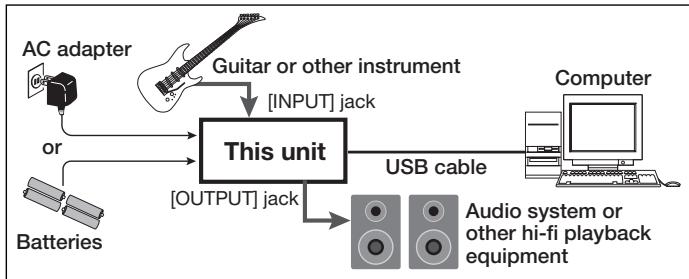
NOTE
- If you monitor the audio signal during recording via the audio output of the computer, there will be an audible latency. Be sure to use the [OUTPUT] jack of this unit to monitor the signal.
- When a device designed to use USB power is powered via the USB cable, insufficient power may result in unstable operation or error indications appearing on the display. In such a case, power the device from an AC adapter or batteries.
- Use a high-quality USB cable and keep the connection as short as possible. If power is supplied to a device designed to use USB power via a USB cable that is more than 3 meters in length, the low voltage warning indication may appear.
HINT
No special steps are necessary for canceling the USB connection. Simply disconnect the USB cable from the computer.
When you connect this unit for the first time to a computer running Windows XP, a message saying "New Hardware Found" will appear. Before proceeding, wait a while until this message disappears.

From the "Start" menu, select "Control Panel" and double-click "Sounds and Audio Devices".
The sounds and audio devices properties screen appears. Click the "Audio" tab and check whether "USB Audio CODEC" is selected as default device for audio playback and recording.
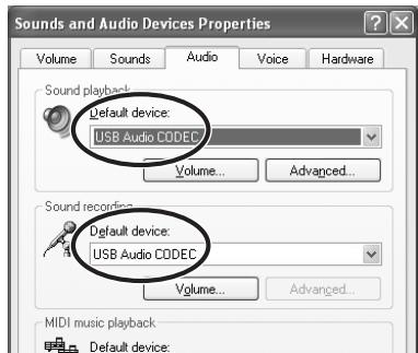
If another device is selected, use the "Default Device" pull-down menu to change the selection to "USB Audio CODEC".
When the setting has been made, click the OK button to close the sounds and audio devices properties screen.

Start Cubase LE.
A window asking whether to check the audio input/output port appears. Click OK to perform the check.

After Cubase LE has started up, access the "Devices" menu, select "Device Setup..." and click "VST Multitrack" in the list of devices.
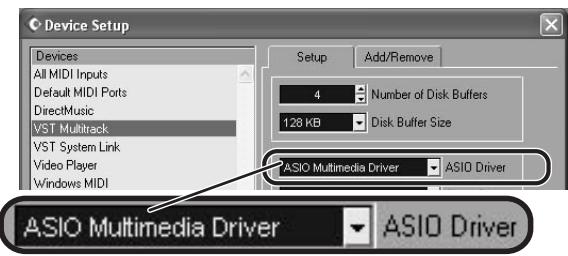
Check whether "ASIO Multimedia Driver" is selected as ASIO driver in the right part of the device setup window.

Click the "Control Panel" button in the device setup window. In the window that appears, click the "Advanced Options" button.
In the advanced options window, check whether "USB Audio CODEC" is selected as input port and output port.
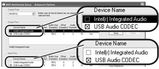
If not selected, click the respective box to place a check mark in it. When the setting has been made, click the OK buttons to close the windows and return to the normal post-startup Cubase LE screen.
HINT
- By clicking the Move up/Move down button in the advanced options window, you can change the priority sequence setting of the currently selected port. If you move "USB Audio CODEC" to the top of the list, it will also be at the top in the following VST input window.
- When you edit any of the settings in the advanced settings window, a window asking whether to check the audio input/output port appears. Click OK to perform the check.

Access the "Devices" menu and select "VST Inputs". The VST inputs window appears. Check whether the input port is active.
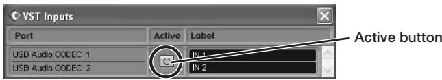
If the Active button is Off (grayed out), click the button to set it to On.
HINT
When multiple input ports are available for selection, you should scroll or enlarge the window and check the enable/disable settings for all ports.

Continued overleaf
Cubase LE Installation
Connections and Preparations
Recording with Cubase LE
MacOS X
To connect this unit to a computer running MacOS X and enable audio input/output, proceed as follows.

Insert the CD-ROM supplied with this product into the CD-ROM drive of the Macintosh computer.
The "Cubase LE" icon appears on the desktop.

Double-click the icon to open it, and use the "Cubase LE Installer" to install Cubase LE.
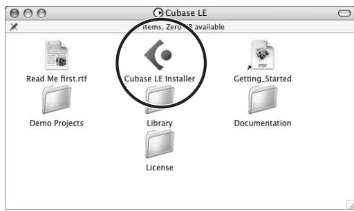

Connect this unit to the computer using a USB cable.
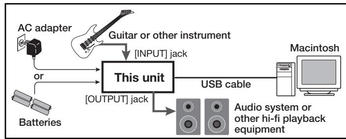
NOTE
- If you monitor the audio signal during recording via the audio output of the computer, there will be an audible latency. Be sure to use the [OUTPUT] jack of this unit to monitor the signal.
- When a device designed to use USB power is powered via the USB cable, insufficient power may result in unstable operation or error indications appearing on the display. In such a case, power the device from an AC adapter or batteries.
- Use a high-quality USB cable and keep the connection as short as possible. If power is supplied to a device designed to use USB power via a USB cable that is more than 3 meters in length, the low voltage warning indication may appear.
HINT
No special steps are necessary for canceling the USB connection. Simply disconnect the USB cable from the computer.

Open the "Applications" folder and then the "Utilities" folder, and double-click "Audio MIDI Setup".
The Audio MIDI Setup screen appears.
Click "Audio Devices" and check whether "USB Audio CODEC" is selected as default input/default output.
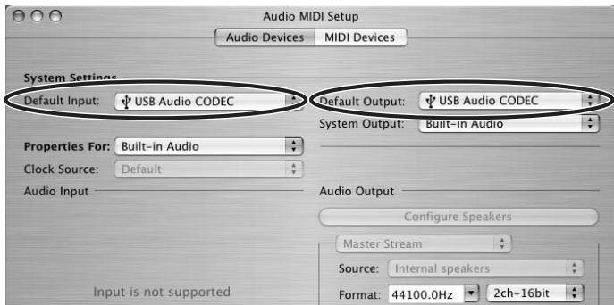
If another device is selected, use the pull-down menu to change the selection to "USB Audio CODEC".
When the setting has been made, close Audio MIDI Setup.

Start Cubase LE.
HINT
The Cubase LE program is installed in the "Applications" folder.

When Cubase LE has started up, access the "Devices" menu, select "Device Setup...", and click "VST Multitrack" in the list of devices.
Check whether "USB Audio CODEC(2)" is selected as ASIO driver in the right part of the device setup window.
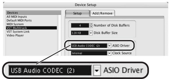
If another item is selected, use the pull-down menu to change the selection.
When the setting has been made, click the OK button to close the window.

Access the "Devices" menu and select "VST Inputs". The VST inputs window appears. Check whether the input port is active.
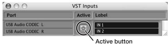
If the Active button is Off (grayed out), click the button to set it to On.

Continued overleaf

Access the "File" menu and select "New Project".
The new project window appears. Here you can select a project template.


Make sure that the "Empty" template is selected, and click the OK button.
A window for selecting the project file save location appears

After specifying the project file save location (such as the desktop), click the OK button (Choose button in MacOS 10.4).
A new project is created, and the project window for controlling most of the Cubase LE operations appears.
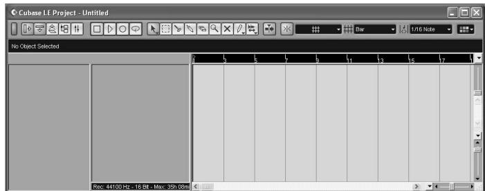
Project window

To create a new audio track, access the "Project" menu and select "Add track". In the submenu that appears, select "Audio".
A new audio track is added to the project window.
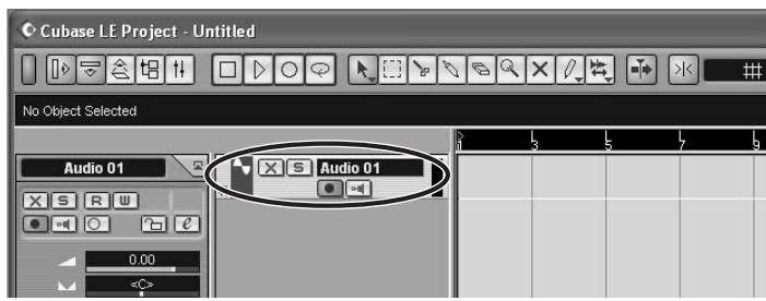
HINT
You can add several tracks at once by accessing the "Project" menu, selecting "Add track" and then selecting "Multiple..." in the submenu.

Make the following settings for the new audio track.
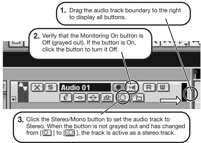

Access the "Devices" menu and select "VST Inputs".
The VST inputs window appears.
This window shows the available input ports and their active/inactive status.
You can perform the following steps here.
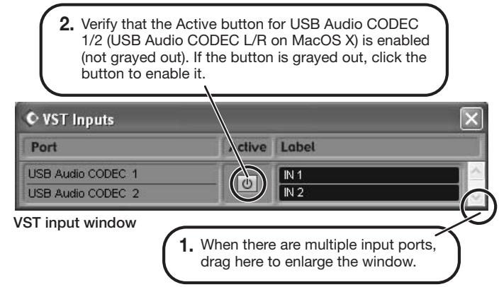

Connect the guitar or other instrument to the [INPUT] jack of this unit and select the desired patch.
The sound selected here will be recorded on the computer via the [USB] port.
![ZOOM G92TT - Connect the guitar or other instrument to the [INPUT] jack of this unit and select the desired patch. - 1](/content/2025/01/152275/images/7bf36ecd5d2974bd5b8a5ef6da929c9e14b9afd71c7c970ea78e314e7cdfed5c.jpg)
Access the "Devices" menu and select "Mixer".
The mixer window appears.
This window shows the channels assigned to created tracks.
You can perform the following steps here.
- Click here to select the port for the USB Audio CODEC 1/2 (USB Audio CODEC L/R on MacOS X) assigned as audio input port to the channel (see step 13).
To adjust the playback level after recording, click this button to bring up the master channel of the mixer.
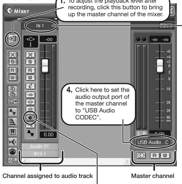
Mixer window
- Verify that the Record Standby button is shown in red. (If the button is grayed out, click the button to enable it. This will set the audio track to the recording standby condition.
HINT
When the Record Standby button is enabled, the level meter next to the fader shows the input level for the audio track. When the button is disabled, the output level for the audio track is shown.

While playing your instrument, adjust the output level of this unit to achieve a suitable recording level for Cubase LE.
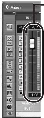
Level meter
When the audio track is in recording standby mode, its recording level is shown by the level meter for the assigned channel. The level should be set in such a way that the meter registers to a fairly high value but remains below the maximum point.
NOTE
- The level meter shows the signal level after internal processing by Cubase LE. Therefore a slight time lag may occur between playing a guitar or other instrument and the meter registering the change in level. This is normal and not a defect.
- The audio tracks of Cubase LE will be recorded with correct timing exactly matched to your instrument play. There will be no lag between already recorded tracks and newly added tracks.

Verify that the transport panel is shown.
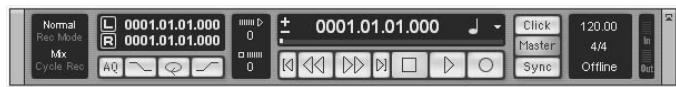
Transport panel
If the transport panel is not shown, access the "Transport" menu and select "Transport Panel".

To start recording, click the Record button in the transport panel.
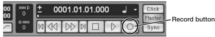
As you play your instrument, the waveform appears in real time in the project window.

To stop recording, click the Stop button in the transport panel.
Recording stops.

Check the recorded content.
To play the recording, perform the following steps.
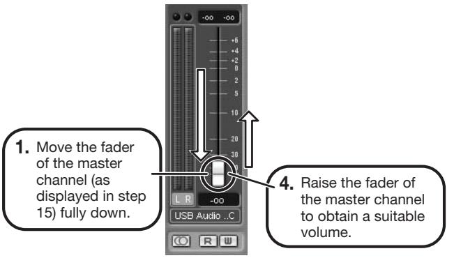
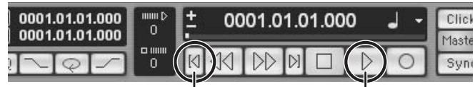
Go to beginning of project
Play button
-
Use the controls on the transport panel to move to the beginning of the project.
-
Click the Play button in the transport panel to start playback.
HINT
If no sound is heard when you click the Play button after recording, check the settings in the VST input window (step 13) and the master channel output port setting (step 15) once more.
For optimum enjoyment
While using Cubase LE, other applications may slow down drastically or the message "Cannot synchronize with USB audio interface" may appear. If this happens frequently, consider taking the following steps to optimize the operation conditions for Cubase LE.
(1) Shut down other applications besides Cubase LE. In particular, check for resident software and utilities.
(2) Reduce plug-ins (effects, instruments) used by Cubase LE. When there is a high number of plug-ins, the computer's processing power may not be able to keep up. Reducing the number of tracks for simultaneous playback can also be helpful.
(3) Power the unit from an AC adapter
When a device designed to use USB power is powered via the USB port, the current supply may sometimes fluctuate, leading to problems. See if using an AC adapter improves operation.
If applications still run very slowly or the computer itself does not function properly, disconnect this unit from the computer and shut down Cubase LE. Then reconnect the USB cable and start Cubase LE again.
Cubase LE 4 installation
Connections and preparation
Use Cubase LE 4 to record
Windows Vista / XP
To connect this unit to a computer running Windows Vista (or Windows XP) and to enable audio input/output, proceed as follows. The installation description uses Windows Vista as an example.

Download the latest ASIO driver from the web site of ZOOM Corporation (http://wwwzoomo.co.jp) and install the driver.
The ASIO driver software is required to enable use of Cubase LE 4 for audio input and output with a computer. Refer to the read_me file included in the download package for instructions on how to install the driver correctly.

Insert the supplied "Cubase LE 4" DVD-ROM into the DVD drive of the computer, and perform the installation steps.
When you insert the DVD-ROM, a screen asking what you want to do appears. Select "Open folder to view files". When the contents of the DVD-ROM are shown, open the "Cubase LE 4 for Windows" folder by double-clicking on it, and then double-click the executable "Setup" ("Setup.exe") file to start the installation process.

Setup
HINT
If nothing happens when you insert the DVD-ROM, open the Start menu and select "Computer" ("My Computer" in Windows XP). Then double-click the "Cubase LE 4" DVD-ROM icon to display the contents of the DVD-ROM.
NOTE
When the installation of Cubase LE 4 is complete, a screen asking about installation of activation (software license authentication) management software appears. Install this software, because it is required for registering Cubase LE 4.

Connect this unit to the computer using a USB cable.
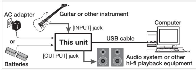
NOTE
- If you monitor the audio signal during recording via the audio output of the computer, there will be an audible delay. Be sure to use the [OUTPUT] jack of this unit to monitor the signal.
- When this unit is operated on USB bus power via the USB cable insufficient power may result in unstable operation or error indications appearing on the display. In such a case, power the device from an AC adapter or batteries.
- Use a high-quality USB cable and keep the connection as short as possible. If USB bus power is supplied to this unit via a USB cable that is more than 3 meters in length, the low voltage warning indication may appear.
HINT
No special steps are necessary for canceling the USB connection. Simply disconnect the USB cable from the computer.
When you connect this unit for the first time to a computer running Windows Vista, a message saying "New Hardware Found" will appear. Before proceeding, wait a while until this message disappears.

Bring up the "Sound" window from the Control Panel and make the input device setting for the computer.
To bring up the "Sound" window, select "Control Panel" from the Start menu and click "Hardware and Sound", then click "Sound".
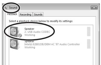
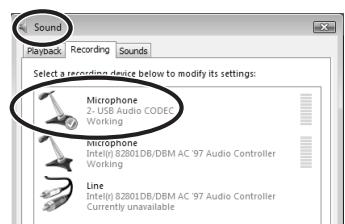
In the "Sound" window, verify that "USB Audio CODEC" is listed under the Play and Record devices and that the device is checked. (To switch between Play and Record, click the tabs at the top of the window.) If the device is not checked, right-click on the icon for the device and click "Set as Default Device" so that a check mark appears.

Start Cubase LE 4. Then access the "Devices" menu, select "Device Setup..." and click "VST Audio System".
To start Cubase LE 4, double-click the Cubase LE 4 shortcut icon that was created on the desktop. After startup, select "ZOOM ASIO Driver" as the ASIO driver in the right section of the Device Setup window. When you change the ASIO driver selection, a confirmation message appears. Click the "Switch" button.
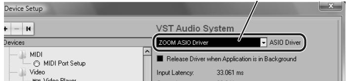
ASIO driver
The device indication in the left section of the window now shows "ZOOM ASIO Driver" as the ASIO driver.
Click on this indication to select it, and then click the "Control Panel" button in the right section of the Device Setup window.
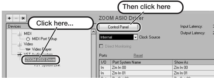
The window that appears lets you set the latency and sampling frequency for the ASIO driver. The latency should be set to a value that is as low as possible without causing sound dropouts during recording and playback.
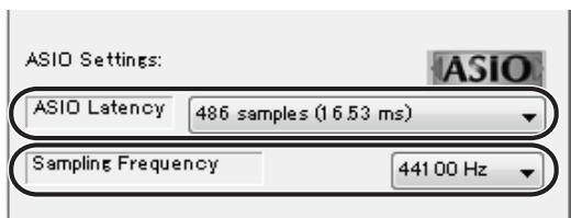
When the setting is complete, click the OK buttons in the respective windows to return to the startup condition of Cubase LE 4.

Continued overleaf
Cubase LE 4 installation
Connections and preparation
Use Cubase LE 4 to record
MacOS X
To connect this unit to a computer running MacOS X and enable audio input/output, proceed as follows.

Insert the supplied "Cubase LE 4" DVD-ROM into the DVD drive of the Macintosh.
The contents of the DVD-ROM appear automatically. If nothing happens when you insert the DVD-ROM, double-click the "Cubase LE 4" icon shown on the desktop.

Install Cubase LE 4 on the Macintosh.
When the contents of the DVD-ROM appear, open the "Cubase LE 4 for MacOS X" folder by double-clicking it, and then double-click the "Cubase LE 4.mpkg" file to start the installation process.

Cubase LE 4.mpkg

Connect this unit to the computer using a USB cable.
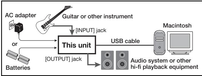
NOTE
- If you monitor the audio signal during recording via the audio output of the computer, there will be an audible delay. Be sure to use the [OUTPUT] jack of this unit to monitor the signal.
- When this unit is operated on USB bus power via the USB cable, insufficient power may result in unstable operation or error indications appearing on the display. In such a case, power the device from an AC adapter or batteries.
- Use a high-quality USB cable and keep the connection as short as possible. If USB bus power is supplied to this unit via a USB cable that is more than 3 meters in length, the low voltage warning indication may appear.
HINT
No special steps are necessary for canceling the USB connection.
Simply disconnect the USB cable from the computer.

Open the "Applications" folder and then the "Utilities" folder, and double-click "Audio MIDI Setup".
The Audio MIDI Setup screen appears. Click "Audio Devices" and check whether "USB Audio CODEC" is selected as default input/ default output.
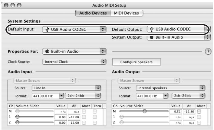
If another device is selected, use the pull-down menu to change the selection to "USB Audio CODEC".
When the setting has been made, close Audio MIDI Setup.

Start Cubase LE 4. Then access the "Devices" menu, select "Device Setup..." and click "VST Audio System".
To start Cubase LE 4, double-click on the Cubase LE 4 icon that was placed in the "Applications" folder during installation.
After startup, be sure to verify that "USB Audio CODEC (2)" is selected as ASIO driver in the right section of the Device Setup window.
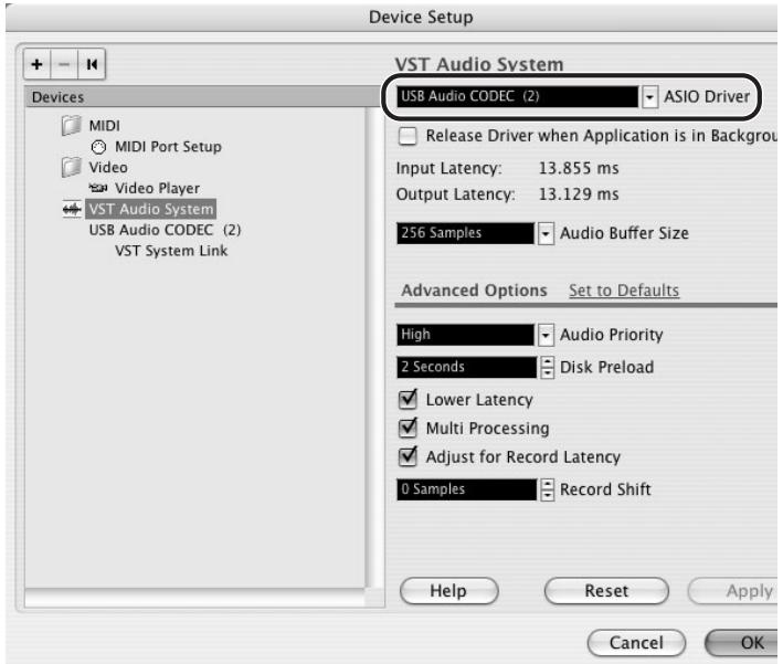
If another item is selected, use the pull-down menu to change the selection to "USB Audio CODEC (2)".
When the setting has been made, click the OK button to close the window.

Continued overleaf
From the "Devices" menu of Cubase LE 4, select "VST Connections" and select the device containing the string "Zm In (Out)" ("USB Audio CODEC" for MacOS X) as input port and output port.
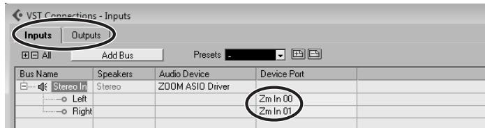
Use the tabs at top (top center for Mac OS X) left to switch between input and output, and verify that "Zm In (Out)" is selected as device port. If another device is selected, click the device port field and change the selection.
7 Access the "File" menu and select "New Project".
The new project window appears. Here you can select a project template.
Make sure that the "Empty" template is selected, and click the OK button.
A window for selecting the project file save location appears.
After specifying a suitable project file save location (such as the desktop), click the OK button (Choose button in MacOS X).
A new project is created, and the project window for controlling most of the Cubase LE 4 operations appears.
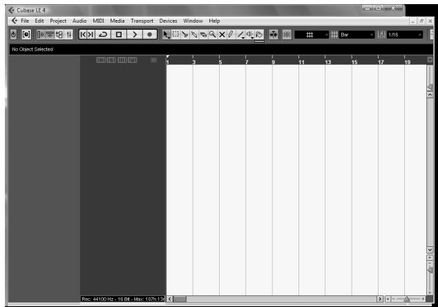
Project window
To create a new audio track, access the "Project" menu and select "Add track". In the submenu that appears, select "Audio".
he Add Track window for specifying the number of audio tracks and the stereo/mono setting appears.
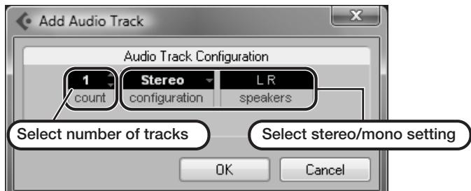
In this example, set the number of tracks to "1" and select stereo, then click the OK button.
A new stereo audio track is added to the project window.
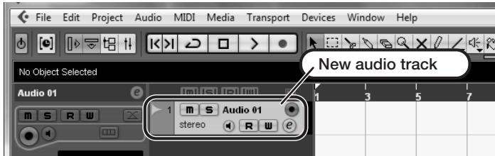
Make the following settings for the newly created audio track.
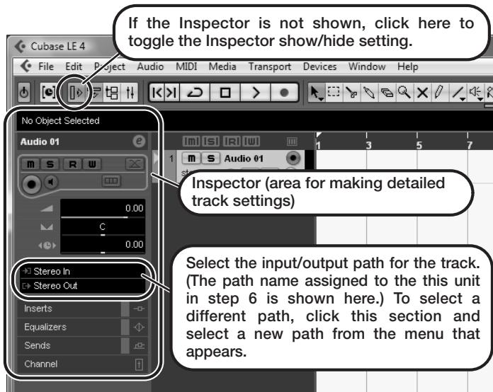
HINT
The Inspector shows information about the currently selected track. If nothing is shown, click on the track to select it.
Connect the guitar or other instrument to the [INPUT] jack of this unit and select the desired patch.
The sound selected here will be recorded on the computer via the [USB] port.
Access the "Devices" menu of Cubase LE 4 and select "Mixer".
The mixer window appears.
This window shows the channel assigned to the created track, and the master channel.
Perform the following steps here.
Mixer window
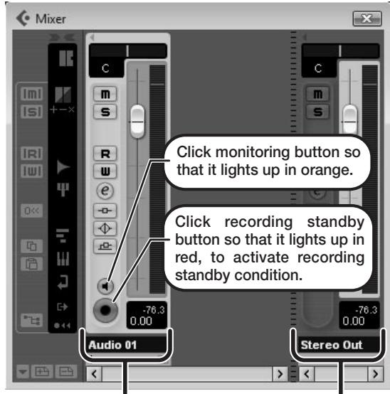
Channel assigned to audio track
Master channel
HINT
When the monitoring button is enabled, the level meter next to the fader shows the input level to the audio track. When the monitoring button is disabled, the meter fader shows the audio track output level.
While playing your instrument, adjust the output level of this unit to achieve a suitable recording level for Cubase LE 4.
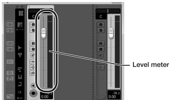
The recording level for Cubase LE 4 can be checked with the level meter for the channel that is assigned to the recording standby track. Set the level as high as possible without causing the meter to reach the end of the scale.
To adjust the level, do not use the fader of Cubase LE 4. Instead change the recording level and gain settings at this unit.
NOTE
- While the monitoring button is enabled, the direct signal input to this unit and the signal routed to the computer and then returned to this unit will be output simultaneously from this unit, causing a flanger-like effect in the sound. To accurately monitor the sound also while adjusting the recording level, temporarily set the output device port for the VST connection (step 6) to "Not Connected".
- The level meter as in the above illustration shows the signal level after processing in this unit. When you pluck a guitar string the meter may register with a slight delay, but this is not a defect.
When the recording level has been adjusted, click the monitoring button to disable it.
The input level is no longer shown on the meter, and the signal returned to this unit via the computer is muted.
In this condition, only the signal before sending to the computer can be monitored via the [OUTPUT] jack of this unit.
Verify that the transport panel is being shown.
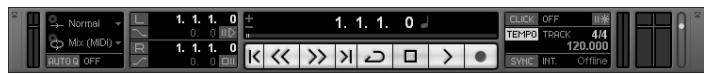
If the transport panel is not shown, access the "Transport" menu and select "Transport Panel".
To start recording, click the Record button in the transport panel.
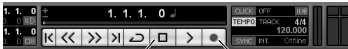
Stop button
Record button
Recording starts.
As you play your instrument, the waveform appears in real time in the project window.
To stop recording, click the Stop button in the transport panel.

Check the recorded content.
To play the recording, perform the following steps.
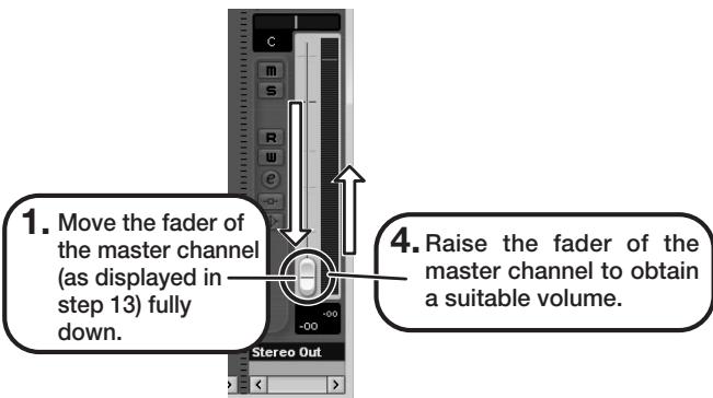
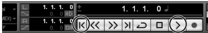
Go to beginning of project
Play button
-
Use the button in the transport panel to move to the beginning of the project.
-
Click the Play button in the transport panel to start playback.
HINT
If no sound is heard when you click the Play button after recording, check the VST connection settings (step 6) once more.
NOTE
To continue using Cubase LE 4, a process called activation (license authentication and product registration) is necessary. When you start Cubase LE 4, a screen offering to register the product will appear. Select "Register Now". A web site for registration will open in your Internet browser. Follow the instructions on that page to register and activate the product.
For optimum enjoyment
While using Cubase LE 4, other applications may slow down drastically or a message such as "Cannot synchronize with USB audio interface" may appear. If this happens frequently, consider taking the following steps to optimize the operation conditions for Cubase LE 4.
(1) Shut down other applications besides Cubase LE 4. In particular, check for resident software and other utilities.
(2) Reduce plug-ins (effects, instruments) used by Cubase LE 4.
When there is a high number of plug-ins, the computer's processing power may not be able to keep up. Reducing the number of tracks for simultaneous playback can also be helpful.
(3) Power the unit from an AC adapter.
When a device designed to use USB power is powered via the USB port, the current supply may sometimes fluctuate, leading to problems. See if using an AC adapter improves operation.
If applications still run very slowly or the computer itself does not function properly, disconnect this unit from the computer and shut down Cubase LE 4. Then reconnect the USB cable and start Cubase LE 4 again.
- GUITAR EFFECTS CONSOLE
- 69.2tt
- Operation Manual
- 200m
- SAFETY PRECAUTIONS Usage Precautions
- SAFETY PRECAUTIONS
- Power requirements
- Environment
- Handling
- Connecting cables and input and output jacks
- Alterations
- Volume
- Usage Precautions
- Electrical interference
- Cleaning
- Please keep this manual in a convenient place for future reference.
- Contents
- Features
- - Latest technology for top performance
- Ready-to-use patches
- - Great for stage work or direct recording
- Built-in tuner supports special tuning requirements
- - Two expression pedals built in as standard
- - Tube powered Accelerator and Energizer
- - Programmable function foot switches
- Terms Used in This Manual
- ■ Effect module
- ■ Effect type
- ■ Effect parameter
- Patch
- Bank and group
- ■ Modes
- - Play mode
- - Manual mode
- Edit mode
- - Store mode
- - Bypass/mute mode
- Controls and Functions
- Getting Connected
- Connection example (3) (External effect connection)
- Power-On
- HINT
- NOTE
- Quick Guide 1 (Play Mode/Manual Mode Operation)
- Selecting a patch (play mode)
- To select a patch, use foot switches 1 - 5.
- [Indication in play mode]
- Turning a module on and off with your foot (manual mode)
- In play mode, keep the BANK [▼] foot switch depressed for more than one second.
- Pre-amp operation
- [Pre-amp section]
- Select the channel for which to make a setting with the [PRE-AMP A/B] keys.
- Turn the knobs of the pre-amp section to make adjustments.
- Press the foot switch for the module to be switched on and off.
- Quick Guide 2 (Edit Mode/Store Mode Operation)
- Editing a patch (edit mode)
- Press the effect module key for the module to edit.
- Use the [TYPE] knob and parameter knobs 1 - 4 to make adjustments.
- Storing a patch (store mode)
- The indication "PATCH" appears in the top right of the display and the indication "STORE?" in the bottom left. Make sure that the operation is what you intend to do.
- Use the BANK [] / [] foot switches and foot switches 1 - 5 to select the store target bank and patch number.
- Press the [STORE/SWAP] key once more.
- Selecting Patches for Playing (Play Mode)
- Panel display
- Group name (U, u, A, b)
- Patch level
- "E" symbol
- Selecting a patch
- Adjusting the sound
- To change other major parameters in the pre-amp section, operate the respective knob (see illustration below).
- To adjust the overall level of the patch, turn parameter knob 2 in play mode.
- Using the Accelerator
- - [TUBE] control
- - Clean - Tube Mix
- [SOLID STATE] control
- - Normal Clean
- Tube Pre-amp
- Using the Energizer
- [TUBE] control
- - [BOOST] control
- Switching Modules On and Off With Your Foot During Play (Manual Mode)
- Using the Internal Tuner (Bypass/Mute Condition)
- Using the chromatic tuner
- Using other tuner types
- of "Using the chromatic tuner".
- Changing the Sound of a Patch (Edit Mode)
- Patch configuration
- Basic edit mode steps
- Select the patch to edit.
- In play mode or manual mode, press the effect module key (see illustration on next page) to select the module on which to operate.
- [Module other than PRE-AMP/EQ]
- [PRE-AMP module]
- [EQ module]
- To switch the selected module between on and off, press the same module key once more.
- To edit the selected module, proceed as follows.
- - When a module other than PRE-AMP/ EQ is selected
- - When PRE-AMP/EQ module is selected
- Changing a patch name
- Storing Patches and Banks (Store Mode)
- Storing/swapping patches
- Storing/swapping banks
- Returning patches to factory default condition
- Turn power to the G9.2tt on while holding down the [STORE/SWAP] key.
- Press the [STORE/SWAP] key once more.
- Using the Expression Pedals
- About the expression. pedals
- Assigning control targets to expression pedal 1
- Press the [PEDAL 1 SETTING] key.
- To use expression pedal 1 for switching the module on and off, turn parameter knob 4 and select "Enable".
- Assigning control targets to expression pedal 2
- Press the [PEDAL 2 SETTING] key.
- Turn parameter knob 1 to select the parameter that is to be controlled.
- To set the adjustment range for the parameter to be controlled, use parameter knob 2 (minimum value) and parameter knob 3 (maximum value).
- To use expression pedal 2 for switching the module on and off, turn parameter knob 4 and select "Enable".
- Repeat steps 3 - 6 to set the other control targets for the vertical direction in the same way.
- To assign control targets for the horizontal direction, turn the [TYPE] knob to select one of the four horizontal direction control targets (P2H1 to P2H4).
- Repeat steps 4 - 5 to set the parameter and minimum and maximum values for the control target.
- Repeat steps 8 - 9 to set the other control targets for the horizontal direction in the same way.
- When all settings for expression pedal 2 have been made, press the [EXIT] key.
- If required, store the patch.
- Adjusting the expression. pedals
- Adjusting expression pedal 1
- Hold down the [PEDAL 1 SETTING] key while turning on power to the unit.
- With expression pedal 1 fully raised, press the [STORE/SWAP] key.
- Using the Function Foot Switches
- Press the [TOTAL/FUNCTION] effect module key.
- TOTAL/FUNCTION
- Turn parameter knobs 2/3 to select the function to be assigned to function foot switches 1/2.
- When parameter knob 2 is turned
- When parameter knob 3 is turned
- PRE-AMP CH A/B
- BPM TAP
- Delay TAP
- Hold Delay
- Delay Mute
- - Bypass Off, Mute OnOff
- COMP OnOff, WAH/EFX1 OnOff, EXT LOOP OnOff, ZNR OnOff, PRE-AMP OnOff, EQ OnOff, MOD/EFX2 OnOff, DELAY OnOff, REVERB OnOff
- After selecting a function to assign to the function foot switch, press the [EXIT] key.
- Specifying the tempo for a patch
- Turn parameter knob 1 to set the tempo.
- To synchronize a parameter to the specified tempo, select the effect type and effect parameter to synchronize, and select the note symbol as the setting value for the parameter.
- Select a parameter value by selecting a note symbol.
- When the tempo and parameter setting is complete, press the [EXIT] key.
- Using the Effect Loop
- Connect the external effect to the EXT LOOP SEND/RETURN jacks.
- Use parameter knob 1 to adjust the level of the signal sent from the G9.2tt to the external effect (send level).
- Select the patch in play mode.
- Press the [EXT LOOP] effect module key to activate edit mode.
- Use parameter knob 2 to adjust the level of the signal sent from the external effect to the G9.2tt (return level).
- Use parameter knob 3 to adjust the level balance between the signal returned from the external effect and the internal signal of the G9.2tt (dry level).
- When the effect loop settings have been made, press the [EXIT] key.
- Store the patch as necessary.
- MIDI Usage Examples
- What you can do with MIDI
- - Send and receive patch switching information via MIDI
- - Send and receive pedal/switch/key operation information via MIDI
- Exchange patch data between two G9.2tt units via MIDI
- Selecting the MIDI channel
- In play mode, press the [AMP SELECT/System] key.
- Turn the [TYPE] knob to select the "MIDI Rx Ch" (MIDI receive channel) parameter.
- Turn parameter knob 1 to select the MIDI channel (1 - 16) on which the G9.2tt will receive MIDI messages.
- Turn the [TYPE] knob to select the "MIDI Tx Ch" (MIDI transmit channel) parameter.
- Sending and receiving patch switching information via MIDI (program change)
- Press the [STORE/SWAP] key to save the changes.
- Using mapping mode
- Turn the [TYPE] knob to bring up the "PC MAP" (program change map) parameter.
- When the setting is complete, press the [EXIT] key to exit the AMP SELECT/System menu.
- Press the [STORE/SWAP] key to save the changes.
- Sending and receiving pedal/switch/key operation information via MIDI (control change)
- ■ Enable control change send/ receive
- ■Assigning control change numbers
- - When module on/off switching is performed
- - When bypass/mute on/off switching is performed
- - When pre-amp section channel A/B switching is performed
- Example for receiving control change messages
- - When control change for expression pedal 1/2 is received
- - When control change for module on/off is received
- - When control change for bypass/mute on/off is received
- - When control change for pre-amp section channel A/B switching is received
- Sending and receiving G9.2tt internal data via MIDI
- Connect the MIDI OUT connector on the source G9.2tt to the MIDI IN connector on the target G9.2tt using a MIDI cable.
- Target G9.2tt
- Set the G9.2tt to play mode and press the [AMP SELECT/System] key. Then use the [TYPE] knob to bring up the "BulkDumpRX" (bulk dump receive) parameter on the display.
- Press the [PAGE] key.
- Source G9.2tt
- Set the G9.2tt to play mode and press the [AMP SELECT/System] key.
- Use the [TYPE] knob to bring up the "BulkDumpTx" (bulk dump transmit) parameter on the display.
- Press the [PAGE] key.
- Other Functions
- Using the ARRM function
- Using the G9.2tt as audio interface for a computer
- Compatible operating system
- Quantization
- Sampling frequencies
- USB Monitor 3/28 USB+DIRECT
- Turn parameter knob 1 to select one of the following settings.
- - USB+DIRECT
- - USB Only
- When the setting is complete, press the [EXIT] key.
- Muting the direct output when using a USB connection
- AMP Select 1/28 FRONT
- Turn the [TYPE] knob to bring up the indication "USB Monitor" (output mode when USB connection is used) on the display.
- About the editor/librarian software
- Adjusting the display contrast
- Turn the [TYPE] knob to bring up the indication "Contrast" (display contrast) on the display.
- Turn parameter knob 1 to adjust the contrast in the range from 1 - 3.
- When the setting is complete, press the [EXIT] key to exit the AMP SELECT/System menu.
- Linking Effects
- - When CABINET module is on
- Switching between live performance sound and direct recording sound
- - When CABINET module is off
- Using the Amp Select Function
- Turn parameter knob 1 to select one of the following settings.
- FRONT
- COMBO R1
- COMBO R2
- STACK R
- When the setting is complete, press the [EXIT] key.
- Press the [STORE/SWAP] key to save the changes.
- Changing the insert position of the pre-amp section and WAH/EFX1 module
- Changing the insert position of the WAH/EFX1 module
- Changing the insert position of the pre-amp section
- In play mode, manual mode, or edit mode, press the [PRE-AMP] key.
- Turn parameter knob 2 to select "Pre" (before MOD/EFX2 module) or "Post" (after DELAY module).
- Effect Types and Parameters
- How to read the parameter table
- Tempo sync
- Expression pedal
- Delay tap/hold delay/delay mute
- COMP module
- Compressor
- RackComp
- Limiter
- WAH/EFX1 module
- AutoWan
- A-Resonance
- Booster
- TOTAL module
- Troubleshooting
- No sound or very low volume
- Sound is distorted
- Foot switches do not operate properly
- Sound in bypass condition is strange
- Noise is noticeable
- Cannot send or receive MIDI messages
- On/off switching with expression pedal does not work properly
- Specifications
- MIDI implementation chart
- The FCC regulation warning (for U.S.A.)
- Operating Dedicated Effects With the Z-Pedal
- X-Wah
- X-Phaser
- X-Vibe
- Z-Oscillator
- MOD/EFX2 module
- Z-Echo
- X-Flanger
- X-Step
- Z-Step
- Z-Pitch
- Z-MonoPitch
- Z-Talking
- REVERB module
- Z-Delay
- Z-Dimension
- Z-Tornado
- Adjusting the Expression Pedal Torque
- Adjusting horizontal torque for expression pedal 2
- Adjusting vertical torque for expression pedal 1/2
- © ZOOM Corporation
- G9.2tt Patch List
- ARTIST
- SPECIAL FX
- Recommended Accelerator settings
- Normal Clean
- Clean-Tube Mix
- Recommended settings for major guitar amps
- Marshall JCM-2000
- Fender Twin Reverb
- Roland JC-120
- Fender Twin Reverb '65
- Fender Tweed Deluxe '53
- Marshall 1959 SuperLead100
- Marshall 1962 Bluesbreaker
- Roland JAZZ CHORUS
- HIWATT Custom 100
- ENGL E650 Ritchie Blackmore Signature 100
- PEAVEY 5150 STACK
- Fender BASSMAN
- VoxAC30TBX
- Marshall JCM2000
- MESA/BOOGIE Dual Rectifier
- Diezel Herbert
- O Hughes & Kettner TriAmp MK2
- G9.2tt Modeling Description ② Reference for drive effect types and its original models.
- BOSS OD-1
- Obanez TS808
- KLON CENTAUR
- Marshall Guv'nor
- O PROCO RAT
- BOSS DS-1
- MXR Distortion+
- MATCHLESS HOT BOX
- 0
- Dallas-Arbiter FUZZ FACE
- Electro-Harmonix BIG MUFF
- BOSS MT-2
- Fender Combo + TS9
- Marshall Stack + SD-1
- Marshall Stack + FUZZ FACE
- OZCombo
- Z Stack
- ZOD
- Extreme Distortion
- Digital Fuzz
- O Z Clean
- Cubase LE Installation
- Connections and Preparations
- Recording with Cubase LE
- Windows XP
- Install Cubase LE on the computer.
- Connect this unit to the computer using a USB cable.
- From the "Start" menu, select "Control Panel" and double-click "Sounds and Audio Devices".
- Start Cubase LE.
- MacOS X
- Access the "File" menu and select "New Project".
- Make sure that the "Empty" template is selected, and click the OK button.
- After specifying the project file save location (such as the desktop), click the OK button (Choose button in MacOS 10.4).
- To create a new audio track, access the "Project" menu and select "Add track". In the submenu that appears, select "Audio".
- Make the following settings for the new audio track.
- Access the "Devices" menu and select "VST Inputs".
- Connect the guitar or other instrument to the [INPUT] jack of this unit and select the desired patch.
- Access the "Devices" menu and select "Mixer".
- While playing your instrument, adjust the output level of this unit to achieve a suitable recording level for Cubase LE.
- Verify that the transport panel is shown.
- To start recording, click the Record button in the transport panel.
- To stop recording, click the Stop button in the transport panel.
- Check the recorded content.
- For optimum enjoyment
- Cubase LE 4 installation
- Connections and preparation
- Use Cubase LE 4 to record
- Windows Vista / XP
- Access the "File" menu and select "New Project".
- After specifying a suitable project file save location (such as the desktop), click the OK button (Choose button in MacOS X).
- Access the "Devices" menu of Cubase LE 4 and select "Mixer".
- Mixer window
- While playing your instrument, adjust the output level of this unit to achieve a suitable recording level for Cubase LE 4.
- When the recording level has been adjusted, click the monitoring button to disable it.
- Verify that the transport panel is being shown.
Brand : ZOOM
Model : G92TT
Category : Guitar effects pedalboard