USER MANUAL BOITIER MURAL FIL PILOTE ATLANTIC
Characteristics / Fitting instructions P.I I
The wall box and programming card P.16
Configuring the programming card P.17
The installation must be made in accordance with normal trade practice and comply with the standards in force in the country of installation (NFC 15100 for France).
I/Technical characteristics
- Wall mounted in a standard recessed box: dia. 60mm depth = 40mm.
- Dimensions: 143 × 80 × 28 ~mm (installed).
- Protection class: IP20.
- Power supply: single-phase 230V / 50Hz mains supply.
- Operating temperature: 0^ C + 40^ C .
- Cabling: 1.5mm2 section without spurring.
- Pilot wire: depending on the model, one or two 6-order pilot wire outputs as per GIFAM standard; each capable of piloting a maximum of 15 heating appliances.

Work with the power switched off when making connections.
II/ Fitting instructions
So that the temperature displayed represents the actual ambient temperature, avoid installing the wall box on a cold wall or in a draught.
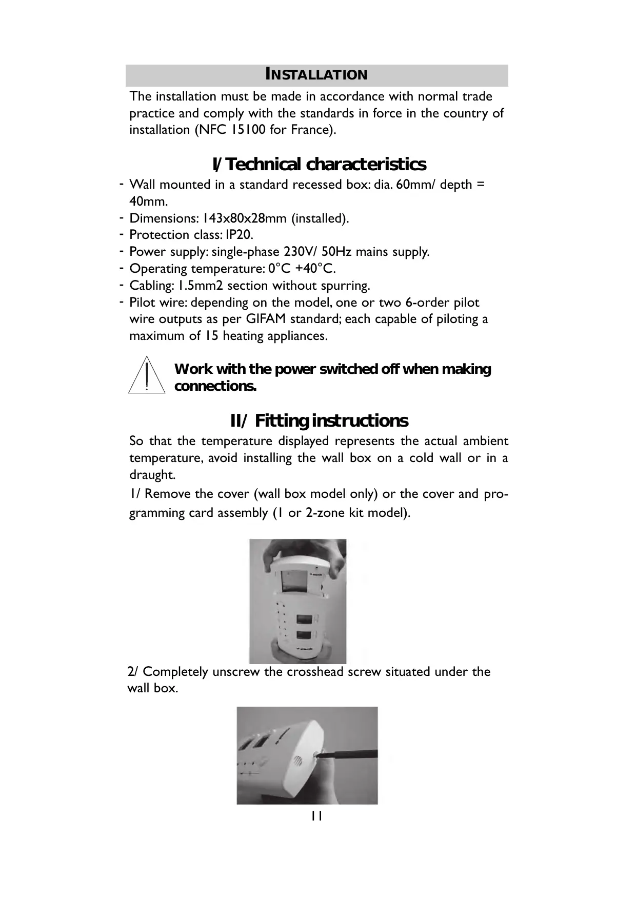
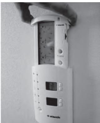
1/ Remove the cover (wall box model only) or the cover and programming card assembly (I or 2-zone kit model).
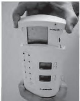
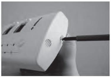
2/ Completely unscrew the crosshead screw situated under the wall box.
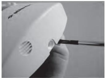
3/ Insert a flat screwdriver in the spur next to the screw and lift to open the wall box. Separate the front section from the base section.

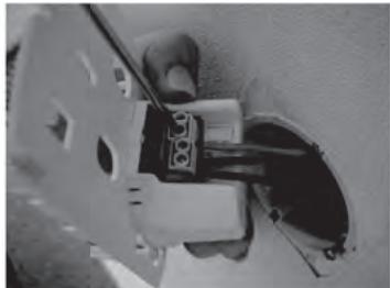
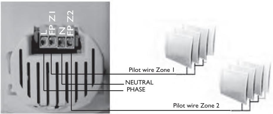
4/ Address the base section and connect the Neutral (N), Live (L) and pilot wire (FP). In the case of the 2-zone model, both pilot wires must be connected (FPZ1 and FP Z2).

To avoid destroying the product, carefully follow the wiring diagram on Page 13.
5/ Fasten the support in the standard recessed box ( 60mm , depth = 40mm ).
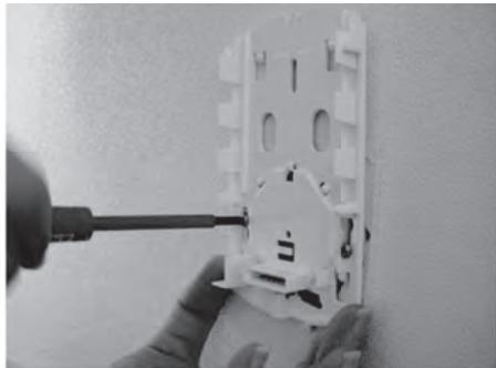
6/ Hook the fascia onto the base and pivot it fully until it is vertical. Reposition the locking screw.
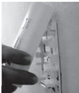
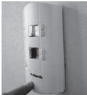
7/ After programming the card (see Page 17), refit the cover or the cover and programming card assembly, depending on the model.
III/Wiring diagram
In the case of installation without an energy controller:
In the case of installation with an energy controller:
Please refer to the controller's manual.
IV/ Commissioning
This product allows you to choose Comfort or Eco as the default mode. This is the mode to which the box returns after a time period only if there is no programming card.
Every time you switch on, the upper display shows "Mod" and the indicator light for the memorised default mode flashes rapidly. For ten seconds, you can alter the mode by pressing the mode change key. After ten seconds, the current mode is automatically recorded as the new default mode and "Mod" is no longer displayed. When you first switch on, Comfort is set as the initial default mode.

In normal operation, a mode change instruction can take 30 seconds to be applied to the heating appliances in the zone.
V/ If you encounter a problem
| Problems encountered | Checks to make |
| Nothing appears on the fascia (the lights and the display are unlit). | Check the installation's wiring
(See wiring diagram on Page 13). |
| The heating appliances do not comply with the programming instructions. |
| Activation of the thermometer function displays too high or too low a temperature. | Remove the fascia (see Page 12) and adjust the calibration wheel inside the box. |
USING A WALL BOX
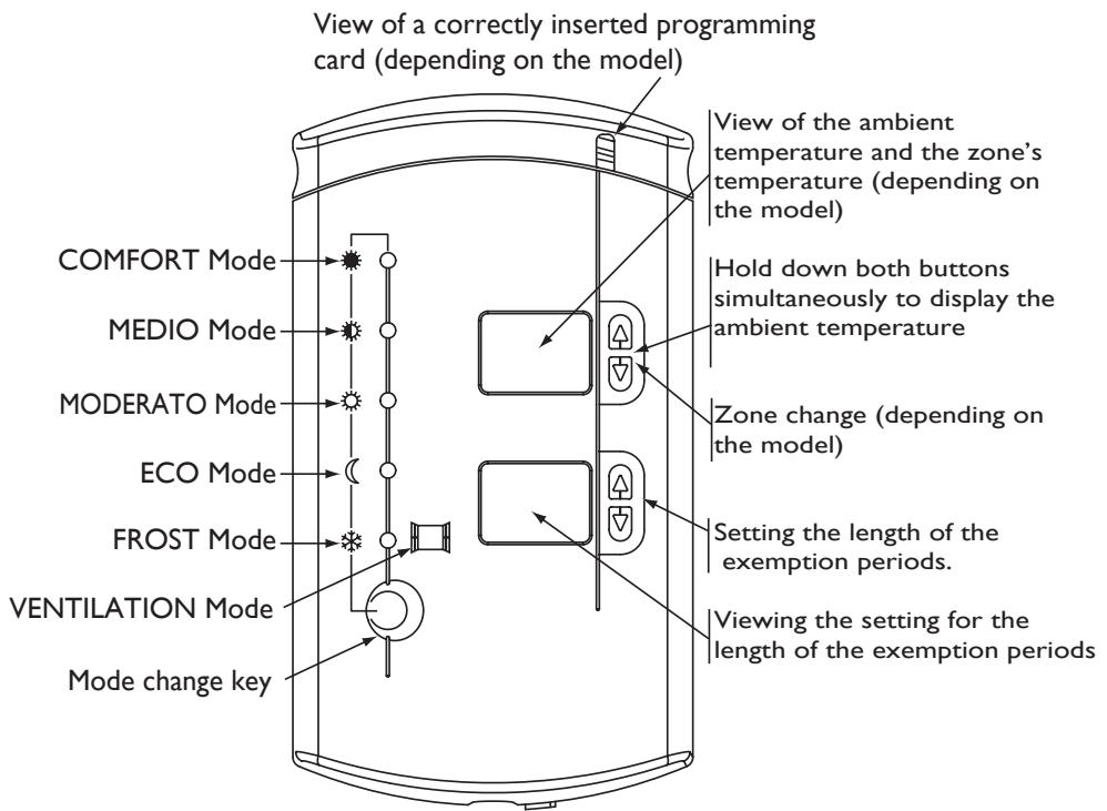
COMFORT Mode: This consists of setting your temperature on each of the knurled wheels on your heating appliances so that they provide a suitable temperature for you, i.e. a comfortable temperature. This can be constant or timed from 1 to 48 hours.
Medio Mode (or Comfort - I°C): this represents a reduction in the temperature in your rooms of I°C compared to the Comfort temperature. This can be constant or timed from 1 to 48 hours.
Moderato Mode (or Comfort -2^ ) : this represents a reduction in the temperature in your rooms of 2^ compared to the Comfort temperature. This can be constant or timed from 1 to 48 hours.
Eco Mode : this represents a reduction in the temperature in your rooms of 3.5^ C compared to the Comfort temperature. This can be constant or timed from 1 to 48 hours.
Frost Mode : this sets the temperature in your rooms at approximately 7^ C . This can be constant or timed from 1 to 99 days.
In the factory configuration, when you set a time period in HG mode, the number of days is displayed followed by the letter “J”. To display “D” as “Day”, hold down the 2 buttons on the lower display simultaneously for 3 seconds.
Airing Mode : this sets the temperature in your rooms at approximately 7^ .
Example of using the modes:
Comfort: When you are present in the house.
Médio: When you leave home for a couple of hours.
Moderato: When you leave home for 4 hours.
Eco: When you leave home for a day's work, for the night or even for the weekend.
Frost: When you leave home for a period of more than 48 hours or even when good weather arrives and the heating must be shut down.
□ Airing: Time to air your house.
Initiating changing the mode :
Use the Mode Change key to run through the indicator lights until you stop on the mode you wish. The green indicator light is then permanently lit and the lower display flashes 2 seconds later.
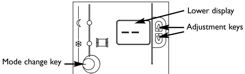
If you wish to set a permanent mode, let the display flash.
If you wish to set a timed mode, use the keys to set the number of hours or days depending on the mode you select.
Example of using a permanent or timed mode :
Permanent mode : to keep a mode the same throughout the day or every day. For example, when the heating season ends, keep to Frost mode until the next season.
Timed mode : to maintain a particular temperature depending on how long you will be away. For example, at night we would recommend Eco mode so that you sleep better (heat disturbs your sleep). If you are going away on holiday for a few days, we recommend that you programme the length of Frost mode so that you can return to a comfortable temperature.
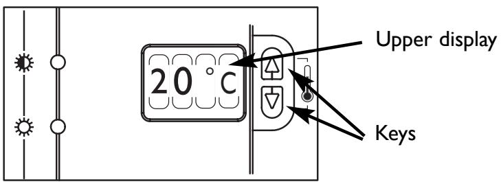
Viewing the ambient temperature:
By holding down both keys simultaneously, you can read, for information only, the temperature measured on the wall box where it is located.
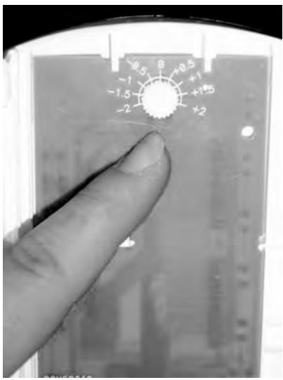
If you notice a difference between the temperature displayed and your reference thermometer, you can adjust the display via the wheel on the back of the fascia. To access this, remove the fascia (see Page 12) and adjust the calibration wheel.
OPTIMISING YOUR HEATING WITH THE PROGRAMMING CARD
This enables you to automate the electric heating to suit your lifestyle. However, your wall box allows you to suspend the programme momentarily.
USING THE WALL BOX WITH
THE PROGRAMMING CARD
The programming card automates the changeovers between Comfort and Eco modes. Therefore, if you are in a Comfort period, the green indicator light remains permanently lit in Comfort mode. If you are in an Eco period, the green indicator light remains permanently lit in Eco mode.
Suspending the programme
This enables you to suspend the current programming temporarily. Using the Mode Change key, set the green indicator light to the mode you wish (Comfort, Medio, Moderato or Eco). This light flashes to indicate that you have left your normal programming and therefore have started suspension. You can select how long you wish to suspend the programme, from 1 to 48 hours, on the lower display.
If no period is set, the suspension will last until the next programme change on the programming card.
Important: If you have selected Frost mode, the green light remains permanently lit because this mode has priority over the programming. It lasts the number of days selected or, by default, until a different mode is selected.
CONFIGURING THE PROGRAMMING CARD
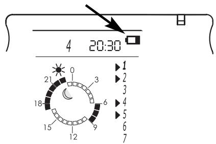
Programming example
It is 20.30 on Saturday.
Setting for the day and the time
Monday, Tuesday, Thursday and Friday: COMFORT mode from 06:00 to 09:00, and from 17:00 to 23:00.
Wednesday: COMFORT mode from 06:00 to 09:00 and from 12:00 to 23:00.
Saturday and Sunday: COMFORT mode from 07:00 to 00:00.
Programme Days
Pressing any key or removing the programming card from the wall box makes the display appear on the screen unless the card has been set for Child Safety. On the other hand, the display automatically goes into hibernation if there is no activity on the keys for more than 4 minutes.
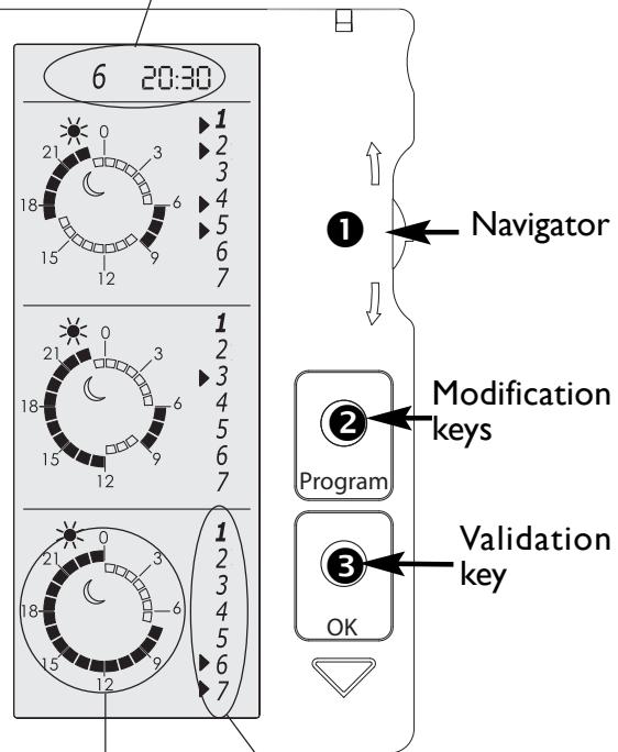
How to set the day and the time. 6 20:30
Move the navigator ① downwards to make the clock zone flash. Pressing the modification key ② enables you to access the mode for setting the day. You can move through the days by moving the navigator ① up or down. Confirm the day by pressing the validation key ③ and proceed in the same way to set the hours and the minutes.
Pressing the validation key ③ confirms the clock setting (the whole clock flashes).
You can move the navigator ① to move to another area or freeze the screen by pressing the validation key ③.
How to programme the card 1 zone.
Move the navigator ① up or down to select the time frame to be altered (the whole time frame flashes).
Pressing the modification key ② enables you to access the time frame selected (the first time slot flashes).
The navigator ① enables you to move through the time frame. The selected element flashes every time you move and the choice of ECO or COMFORT can be modified by pressing the modification button
Pressing the validation key ③ confirms the programming (the time frame flashes).
You can move the navigator ① to move to another area or freeze the screen by pressing the validation key ③.
Assigning days to the programming.
Move the navigator ① up or down to select the day area to be changed.
Pressing the modification key enables you to access the day area to be selected (the first day flashes).
The navigator ① enables you to move through the days: The selected element flashes every time you move. The day selected can be altered by pressing the modification key ② (in the example shown, Thursday is selected).
Pressing the validation key ③ confirms the days.
You can move the navigator ① to move to another area or freeze the screen by pressing the validation key ③.
How to programme the card 2 zones (depending on the model).
To activate the second zone, press the navigator inwards into the card.
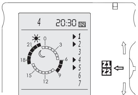
Then set the programming for each zone (see Page18, How to programme the card I zone).
Child safety
Press down the validation key ③ and then pres the modification key ② to set the programming card in Child Safety mode (the keys are then deactivated).
Proceed in the same way to reactivate the programming card.
Maintenance
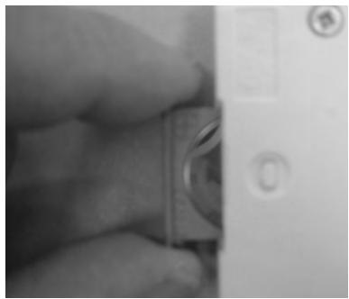
The battery must be changed when the battery symbol is displayed (button-style battery CR 2032).
Warning

Take care not to let any foreign bodies penetrate into the wall box when it is without its programming card.
WARRANTY CONDITIONS
KEEP THIS DOCUMENT IN A SAFE PLACE
(To be presented by the user only in the event of a claim)
- The guarantee period is two years from the date of installation or purchase and may not exceed 30 months from the date of manufacture in the absence of a receipt.
- The guarantee covers the replacement and supply of components recognised as being defective, excluding any damages or interest.
- The user is responsible for any labour or transport costs.
- The guarantee does not cover any damage arising from improper installation, abnormal use or non-observation of the requirements of the said instructions for installation and use.
- The stipulations of the present guarantee conditions do not exclude any of the purchaser's legal rights of guarantee against faults or hidden defects, which are applicable in all cases under the stipulations of Articles 1641 of the Civil Code.
- Present this certificate to your distributor or installer only in the event of a claim, together with your purchase invoice.
TOUR ATLANTIC LTD
Malling Works, Lewes
East Sussex BN7 2AY
Phone 01 580 2431 53
Fax: 01 580 2411 80
E-mail: sales@tour-atlantic.ltd.uk
ATL Internat. tel : (33) 146836000 / (33) 2 38713846
Fax:(33)146836001
INSTALLER'S STAMP
INSTALACION
C/Orense, 20, I° Of.8
28020 MADRID
Tel: 902454566
Fax: 91 555 78 07