
ULYSSE - Towel warmers ATLANTIC - Free user manual and instructions
Find the device manual for free ULYSSE ATLANTIC in PDF.
| Product type | Wall-mounted electric towel warmer |
| Brand | ATLANTIC |
| Model | ULYSSE |
| Category | Towel warmer |
| Power supply | 230 V single phase 50 Hz |
| Operating modes | Heating, Turbo Max 2h, Programming (Comfort, Eco, Frost Protection, Off) |
| Programming | By pilot wire with external programmer; hourly pins on dial (15 min per pin) |
| Turbo function | Max 2h, automatic stop after 2h |
| Overheating protection | Automatic shutdown if grilles are obstructed |
| Child safety | Do not leave children unsupervised; hot surface; protective grille recommended |
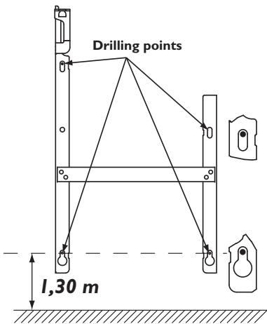
| Installation | Wall-mounted; drilling points less than 1.30 m from the floor |
| Connection | Direct to mains without intermediate switch; junction box at least 25 cm from floor |
| Electrical class | Class II (zones 2 and 3 according to EN 60335-2-30) |
| Maintenance | Dust the grilles 2 times a year; professional inspection every 5 years; clean with a damp cloth |
| Warranty | 2 years (up to 30 months without proof of purchase) |
| Repairability | Intervention by qualified professional; power cable replaceable by after-sales service |
Frequently Asked Questions - ULYSSE ATLANTIC
User questions about ULYSSE ATLANTIC
0 question about this device. Answer the ones you know or ask your own.
Ask a new question about this device
Download the instructions for your Towel warmers in PDF format for free! Find your manual ULYSSE - ATLANTIC and take your electronic device back in hand. On this page are published all the documents necessary for the use of your device. ULYSSE by ATLANTIC.
USER MANUAL ULYSSE ATLANTIC
The device you have just purchased was submitted to many tests and checks ensuring its quality. We thank you for your choice and trust. We hope you will be fully satisfied.
A few recommendations:
Read the instructions before installing the device.
Power the device off before working on it, and check the power supply voltage.
Store the instructions for the future reference after installation.
Classification of the device: (shown on the information label)
Cat C
: Complies with EU standards for this category.
IP24
: Protected against water projections.
Classe II
: Dual insulation.
INSTALLING THE DEVICE
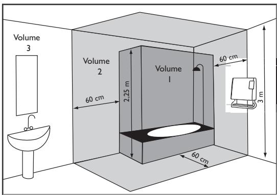
I/ Location of the device
- This device was designed to be installed in residential premises. In any ther case, please call your distributor.
- Installation must comply with the standards currently enforced in the country of use.
- Locate the device within minimum distances from obstacles.
Do not install the device :
In a draft likely to affect its control (under centralised mechanical ventilation, etc...).
Under a fixed mains outlet.
- Inside zones 0 and I in bathrooms.
The device is to be installed so that switches and other controls cannot be touched by a person in the bath or shower, except in the UK where IEE Regulations 701.512.2 and 701.512.3 apply. These allow the use of IP24 rated products and their integral controls in Zone 2 and outside zones.
We strongly advise against installing vertical machines above an altitude of 1000m (risk of faulty operation).
Installing a machine at altitude causes an increase in air output temperature (of the order of 10^ per 1000m above sea level).
It is forbidden to install a vertical machine horizontally or vice versa.
Do not use the device in mobile, on feets or on casters.
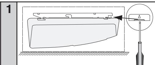
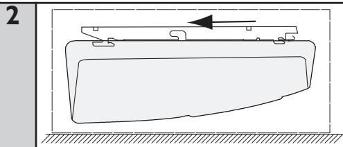
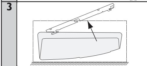
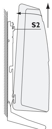
2/ Release the device's hook-on bracket
We recommend that you place the device flat, face down.
Have a straight head screwdriver to hand.
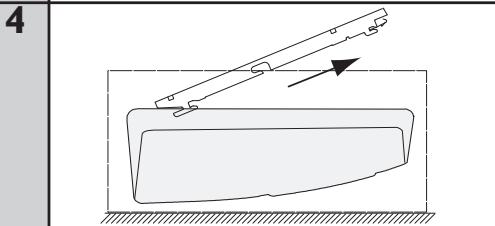
3/ Fix the hook-on bracket
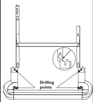
4/ Fastening the towel holder
| 1 | Remove and retain the two screw covers | |
| 3 | - Fit the whole assembly using the screws provided. - Clip the two screw covers over fixings. |
2 -Place the towel holder up against the lower parts of the wall bracket. Mark and drill the fixing holes.
5/ Connecting the device
- The device must be supplied with 230V, 50Hz.
- Mains connection must be ensured using the 3-wire cable factory fittings to the device, through a connecting box. In damp premises, such as bathrooms and kitchens, install the connecting box at least 25cm from the ground.
- The installation must comply with local national regulation. If in doubt, ask the national Atlantic distributor.
- Ground connection is forbidden.
Do not connect the pilot wire (black) to ground. - If power cable is damaged or too
short, to avoid any danger it must be replaced by a qualified electrician using special tools.
- If a device pilots or is piloted by a 30mA differential (e.g. bathroom), the pilot wire supply must be protected on this differential.
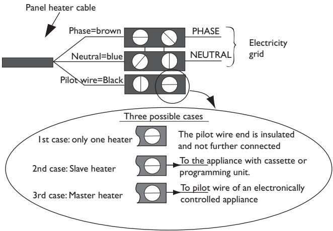
Chart indicating the orders the device can receive over its pilot wire
(to be measured between the pilot wire and the neutral).
| Orders received | Current absent | Full wave 230V | Negative half wave -115V | Positive half wave +115V |
| Ref/neutral oscilloscope | — | — | — | — |
| Mode achieved | COMFORT | ECO | STANDBY | STOP HEATING LOAD SHEDDING |
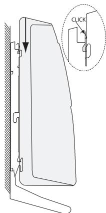
6/ Lock the device on the hook-on bracket
USING THE DEVICE
1) Description of the control box
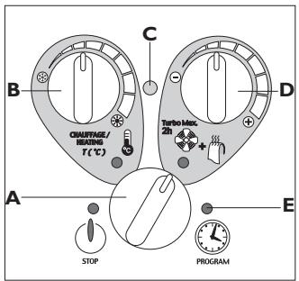
A Mode switch wheel
B Heating wheel
C Heating indicator
D Turbo Max 2h wheel
E Programming mode indicator
2) Heating mode
This mode enables you to maintain the desired temperature in the room.
a) Set the switch A to Heating.
b) Set wheel B, the heating indicator C lights up if the ambient temperature is lower than the temperature desired.
c) Wait a few hours for the temperature to stabilise.
d) If the setting suits you (use a thermometer to check, if need be), mark the position once and for all. If you do not like the setting, readjust it and return to point c.
3) Anti-Frost mode
This mode enables you to maintain the temperature in the room at around 7^ during prolonged absences from home (generally more than 24 hours).
a) Leave the switch A set to Heating.
b) Set wheel B to
4) Turbo Max 2h mode
This mode enables you to increase the room's temperature rapidly and to heat your towels.
a) Set the switch A to Turbo Max 2h.
b) Set wheel D to adjust the desired temperature.
If you forget about it, the Turbo function will be cut off automatically after 2 hours. The device then goes to Stop mode. In this case, remember to reset the switch A to the desired mode (otherwise the device will stay in Stop mode).
5) Using the pilot wire
This device is fitted with a thermostat capable of receiving instructions via its pilot wire. It recognises the following instructions:
- COMFORT :The temperature set by wheel B.
- COMFORT -I :The temperature set by wheel B: -1^
- COMFORT -2 :The temperature set by wheel B: -2^
- ECO :Comfort temperature reduced by approx. 3 to 4^
- ANTI-FROST :Ambient temperature maintained at around 7^
- STOP :The heating stops immediately (used for power cuts).
To activate pilot wire control, position the switch A to Program
By thus connecting the pilot wire to a programmer, you can control the heating in the desired mode (Comfort, Comfort-1°C, Comfort -2°C, Eco or Anti-Frost).
When you are in Program mode, the pilot wire only acts on the heating temperature. You continue to switch to Turbo at the times you have selected using the pegs on the clock (except in the case of the Anti-Frost or Stop instruction).
When you exit Program mode (switch A), the pilot wire no longer affects your device except for Stop mode (in the case of a power cut).
6) Programming mode
This mode enables you to switch automatically from Heating mode to Turbo Max 2 h mode.
a) Set the time: turn the dial on the clock in a clockwise direction until the current time (i.e. the time on your watch) is facing the arrow at the top on the right-hand side. Fine tune if necessary by turning the central pointer.
b) Select your daily programme: opposite the hour markings, tilt the pegs towards the inside for Heating mode and towards the outside for Turbo Max 2 h mode (1 peg = 15 minutes operation).
c) Set the switch A to Program ① to activate your programming.
Example:
You occupy the bathroom from 7:00 to 8:00 AM and 9:00 to 10:00 PM.
You programme Turbo Max 2h mode from 6:30 to 7:30 AM (8:30 if drying towels) and from 8:30 to 9:30 PM.
WARNING
- It is forbidden to cover or obstruct the device's upper and lower grills completely or even partially: other wise there is a risk of overheating. If the grills should be obstructed accidentally, the device stops automatically when the maximum safe temperature is reached.
However, the 'ON' indicator light may stay lit and the clock continues to operate.
To restart, remove the item blocking one of the device's grills and set the switch A to Stop. Wait for approximately 15 minutes and then restart the device. - This device is not intended for use by persons (including children) with physical, sensory or mental disability, or by persons lacking experience or knowledge, unless they have received from a person in charge of their safety adequate supervision or preliminary instructions on how to use the device.
- Please ensure that children do not lean on the device or play close to it when it is operating : its surface may be hot enough to cause burns to their skin in some circumstances, particularly because their reflexes may not yet have been acquired or are slower than those of an adult. If there is any risk, fit a protective grill in front of the device.
- Take care not to allow any foreign bodies or paper to enter the device.
- Any work inside the device must be done by a qualified professional tradesman.
- When conducting any work on the device, it is essential that it be set to the STOP position and have cooled down before being unhooked from its bracket.
MAINTENANCE
- To maintain the device's performance, the upper and lower grills must be cleaned with a vacuum cleaner or a brush approximately twice a year.
- Every five years, have the internal components checked by a qualified electrician (cleaning and interfacing).
- In dirty environments, stains may appear on the device's grill. This is caused by poor quality ambient air. Such stains do not justify replacement of the device under guarantee.
- The casing can be cleaned with a damp cloth. Never use any abrasive products.
WARRANTY CONDITIONS
KEEP THIS DOCUMENT IN A SAFE PLACE
(To be presented by the user only in the event of a claim)
- The guarantee period is two years from the date of installation or purchase and may not exceed 30 months from the date of manufacture in the absence of a receipt.
- The guarantee covers the replacement and supply of components recognised as being defective, excluding any damages or interest.
- The user is responsible for any labour or transport costs.
- The guarantee does not cover any damage arising from improper installation, abnormal use or non-observation of the requirements of the said instructions for installation and use.
- The stipulations of the present guarantee conditions do not exclude any of the purchaser's legal rights of guarantee against faults or hidden defects, which are applicable in all cases under the stipulations of Articles 1641 of the Civil Code.
- Present this certificate to your distributor or installer only in the event of a claim, together with your purchase invoice.
TYPE OF APPLIANCE*:
SERIAL NUMBER*:
CUSTOMER'S NAME AND ADDRESS:
- This information can be found on the information plate situated on the left-hand side of the appliance.
FOR SALES IN THE U.K
TOUR ATLANTIC LTD
Malling Works, Lewes
East Sussex BN7 2AY
Phone: 01580243153
Fax: 01580241180
e-mail: sales@tour-atlantic.ltd.uk
FOR SALES IN NEW ZEALAND
ATLANTIC AUSTRALASIA
Website: www.atlantics.co.nz
Phone: 0800 422 000
Fax: 0011 64 43 800 509
OTHER COUNTRIES
ATLANTIC INTERNATIONAL
Phone: 00 33 146638000