Mon Soleil Frame Wi-Fi - Electric heater Eurom - Free user manual and instructions
Find the device manual for free Mon Soleil Frame Wi-Fi Eurom in PDF.


| Product type | Electric radiator |
| Brand | Eurom |
| Model | Mon Soleil Frame Wi-Fi |
| Power supply | 230 V ~ 50 Hz |
| Power | 1500 W |
| Dimensions (W x H x D) | 60 x 40 x 8 cm |
| Weight | 5 kg |
| Wi-Fi connection | Yes, via dedicated app |
| Heating type | Infrared radiation |
| Thermostat | Electronic, adjustable |
| Timer | Weekly programming |
| Frost protection | Yes |
| Overheat protection | Yes, automatic shut-off |
| Child safety | Key lock |
| Wall mounting | Yes, kit included |
| Care and cleaning | Dust with a dry cloth |
| Spare parts | Available on Eurom website |
| Repairability | Repairability index: 8/10 |
| Energy class | Class A |
Frequently Asked Questions - Mon Soleil Frame Wi-Fi Eurom
User questions about Mon Soleil Frame Wi-Fi Eurom
0 question about this device. Answer the ones you know or ask your own.
Ask a new question about this device
Download the instructions for your Electric heater in PDF format for free! Find your manual Mon Soleil Frame Wi-Fi - Eurom and take your electronic device back in hand. On this page are published all the documents necessary for the use of your device. Mon Soleil Frame Wi-Fi by Eurom.
USER MANUAL Mon Soleil Frame Wi-Fi Eurom
Mon Soleil Frame Wi-Fi
360 / 600 / 720
User manual
NL 3
EN 30
DE 56
FR 83
SV 110
DA 134
CS 158
SK 182
RO 206
INTELLIGENT
THERMOSTAT READY
This product is only suitable for well insulated spaces or occasional use.
Wi-Fi thermostat (OPTIONAL)
| Wi-Fi thermostat | 365764 |
| Wi-Fi thermostat (Swiss plug) | 365771 |
| Wi-Fi thermostat USB-C | 365788 |
Figuur 3.
Figuur 4.
Bedieningspaneel en leddisplay
- Display
- Vermogensaanduiding
- Wi-Fi thermostaat indicatie
- Wifi-aanduiding
- Open-raamaanduiding
- Verwarmingsaanduiding
- Min-knop
- Plus-knop
- MODE-knop (modus)
- AAN/UIT-knop

Figuur 5.
Afstandsbediening

LET OP
Figuur 8.
Figuur 9.
Verticale wandmontage
Figuur 10.

Figuur 11.
Horizontale wandmontage
Figuur 12.

Figuur 13.
De voetjes monteren

WAARSCHUWING
Figuur 14.

natural_image
Diagram of a flat-panel monitor with two triangular supports and a numbered component (1), no text or symbols present.Figuur 15.
Figuur 16.
Figuur 18.

Figuur 19.
Temperatuursensor

LET OP
Figuur 20.
Installatie

WAARSCHUWING
Figuur 21.
Afstandsbediening
Figuur 22.
Werking

WAARSCHUWING
Figuur 23.
Apparaatbediening
Temperatuurinstelling
Figuur 24.
Slimme timer
Please read and understand these safety instructions. Incorrect use can cause injury and will void EUROM's warranty.

WARNING
- Do not use this heater in small rooms when they are occupied by persons not capable of leaving the room on their own, unless constant supervision is provided.
- To reduce the risk of fire, keep textiles, curtains, or any other flammable material a minimum distance of 1 m.

CAUTION
Some parts of this product can become very hot and cause burns. Particular attention has to be given where children and vulnerable people are present.

WARNING
In order to avoid overheating, do not cover the heater.
- Children of less than 3 years should be kept away unless continuously supervised.
- Children aged from 3 years and less than 8 years shall only switch on/off the appliance provided that it has been placed or installed in its intended normal operating position and they have been given supervision or instruction concerning use of the appliance in a safe way and understand the hazards involved. Children aged from 3 years and less than 8 years shall not plug in, regulate and clean the appliance or perform user maintenance.
- This appliance can be used by children aged from 8 years and above and persons with reduced physical, sensory or mental capabilities or lack of experience and knowledge if they have been given supervision or instruction concerning use of the appliance in a safe way and understand the hazards involved. Children shall not play with appliance. Cleaning and user maintenance shall not be done by children without supervision.
- Heater must not be located immediately below a socket-outlet.
- If the supply cord is damaged, it must be replaced by manufacturer, its service agent or similarly qualified persons in order to avoid a hazard.
- Do not use this heater in the immediate surroundings of a bath, a shower or a swimming pool.
- This heater is not suitable for installation in the bathroom.
- Do not use this heater if it has been dropped.
- Do not use if there are visible signs of damage to the heater.
- Use this heater on a horizontal and stable surface, or fix it to the wall, as applicable.
When using the Mon Soleil heater freestanding with the supplied plastic pedestals or in combination with the optionally available Freestanding support (article number 361278):
- Use this heater on a horizontal and stable surface.
The device is equipped with an overheating protection, which switches it off automatically in case of internal overheating. Switch the device off, unplug the power plug, remove the source of overheating, let it cool down and use as normal. Do not use the device if the source of overheating cannot be traced or if the problem persists, but always contact your supplier.
General safety instructions

WARNING
- Prevent splashing water on or in the device.
- Do not immerse any part of the device in water or other liquids.
- Never insert fingers or other objects into the openings of the device.
- Do not expose the device to strong vibrations or mechanical stress.

WARNING
The device becomes very hot during use. Do not touch the device during use or within five minutes after use.

CAUTION
Do not cover the device during usage or after use while the device is still hot. To reduce the risk of fire, keep textiles, curtains, tent canvasses and other flammable material at a minimum distance of 1 meter from the device.
Safety during operation

WARNING
Do not use the device:
- outdoors or in a small space (< 7m^3) ;
- lying, leaning or standing without the pedestals correctly mounted;
- if any parts are dirty or wet;
- near large objects, like behind a door, under a shelf or near a cupboard;
- near or in a dusty and dirty environment, like a construction site;
- near flammable materials, liquids or fumes, e.g. in a shed, stable or green house;
- near other heat sources and open fire;
- with an appliance that automatically switches the device on, such as a timer, dimmer or any other device.
If the device, the electric cable or plug shows damage or is malfunctioning, immediately take the appliance out of use and disconnect the power supply.
Warranty
EUROM offers a 60-month warranty on this device from the date of purchase. The warranty does not cover wear and tear from normal use. The warranty expires if a defect is the result of
unintentional or careless use of the device. The manufacturer, importer and supplier are not liable for incorrect connections.
Introduction
Thank you for choosing this EUROM device. You have purchased a quality device that you will enjoy for many years. Using this device with respect and care will reduce the risk of personal injury or material damage.

CAUTION
It is important to read and understand this instruction manual before assembling, installing and using the device.
This manual describes the correct and safe use of this device. Keep this manual for future reference. The manual is an essential part of the device and must be given to the new owner upon resale or exchange. This manual has been compiled with the utmost care. Nevertheless, we reserve the right to improve and adjust this manual at any time. The images used may differ.
The following symbols and terms are used in this manual to alert the reader to safety issues and important information:

WARNING
Indicates a hazardous situation which, if the safety instructions are not followed, can lead to injuries to the operator or bystanders, light and/or moderate damage to the product or to the environment.

CAUTION
Indicates a hazardous situation which, if the safety instructions are not followed, can lead to light and/or moderate damage to the product or to the environment.
Identification

Art. nr.
Batch.
Mon Soleil Frame *** Wifi
*****
*****
220-240V \~ 50-60Hz - *** Watt


EUROM - KOKOSSTRAAT 20 - 8281 JC - GENEMUIDEN - NETHERLANDS - info@eurom.nl
Figure 25.

Figure 26.
Specifications
| Type: | Mon Soleil 360 Frame Wi-Fi | Mon Soleil 600 Frame Wi-Fi | Mon Soleil 720 Frame Wi-Fi |
| Product size: | 59.5 x 59.5 cm | 59.5 x 99.5 cm | 59.5 x 119.5 cm |
| Weight: | 4.4 kg | 6.8 kg | 8.1 kg |
| Voltage: | 220-240V / 50-60Hz | 220-240V / 50-60Hz | 220-240V / 50-60Hz |
| Power: | 310-360W | 520-600W | 620-720W |
| Protection rating: | IP20 | IP20 | IP20 |
| Protective class: | Class I | Class I | Class I |
Hereby, Euromac b.v. declares this product is in compliance with Directive 2014/53/EU.
The full text of the EU declaration of conformity is available at the following internet address: www.eurom.nl/declaration-of-conformity.
- Wi-Fi and Bluetooth Frequency Band: 2.4 \~ 2.4835GHz
• Maximum radio-frequency power transmitted in this frequency band(s):
° Wi-Fi: 17.5dBm
- Bluetooth: 6.5dBm
Description
The Mon Soleil 360 600 720 Frame Wifi is an easy-to-use electric heater for indoor use. The device can be mounted on a wall or ceiling or freestanding with the supplied plastic pedestals. The Mon Soleil 360 600 720 Frame Wifi can be used with the Eurom Smart App and can be programmed on a day and a week timer.
Unboxing

Figure 27.
| No. | Description | No. | Description |
| 1 | The heater | 5 | Mounting screws and wall plugs (8x) |
| 2 | External temperature sensor | 6 | M4 screws 12 mm (2x) |
| 3 | Pedestals with pre-mounted screws (2x) | 7 | Distance holder for brackets |
| 4 | Remote control | 8 | Brackets (2x) |
Overview
- Main body
- Remote Control
- ON/OFF switch
- Internal temperature sensor
- Control panel and LED display
- Power plug

Figure 28.
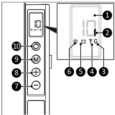
Control panel and LED display
- Display
- Power indication
- Wi-Fi thermostat indication
- Wi-Fi indication
- Open window indication
- Heating indication
- Minus button
- Plus button
- Mode button
- ON/OFF button

Figure 29.
Remote control

ATTENTION
Batteries not included.
- Open window button
- SET button
- OK button
- ECO button
- Calibration button
- TIME OFF button
- Minus button
- WEEK button
- Plus button
- TIME ON button
- Temperature button
- EDIT button
- Cancel button
- ON/OFF button
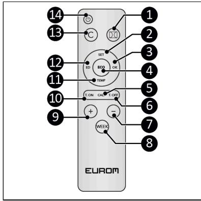
Figure 30.
Transport and storage
- Clean the device before storing it.
- Transport the device in an upright position.
- Store the device in an upright position, in its original packaging, in a cool, dry and dust-free area.
Assembly

WARNING
Plastic bags can be dangerous. To avoid danger of suffocation, keep this bag away from babies and children.
The device is packed in one box. Remove all packaging material and check that the device is not damaged. Do not use the device if it is damaged, but always contact your supplier. Keep the packaging for safe storage and transport.
Mounting

WARNING
The wall or ceiling used for mounting must be made from non-flammable material and should be able to withstand a minimum temperature of 125^ C.

CAUTION
Make sure to use suitable fastening materials, depending on the surface. The provided anchor bolts are suitable for a brick wall. Never block the space between the device and the wall or ceiling.
The device can be mounted in four ways:
• vertically to the wall;
• horizontally to the wall;
• freestanding with the pedestals mounted;
- to a ceiling.
In all four of the placements, the control panel should be visible and operable.
Wall mounting
- Place the device on a vertical and solid wall. Use a level when placing the device.
- Place the device (horizontally or vertically) with a minimum distance of:
A. 30 cm from the side walls;
B. 30 cm from the ceiling;
C. 20 cm from the floor;
D. 50 cm clearance on the front side.
- Do not mount the device immediately over, near or below a socket outlet.

Figure 31.
Assembling the bracket

CAUTION
Make sure the openings of both brackets point upwards, see Figure 32 and Figure 33 for reference.
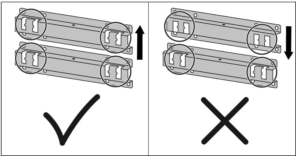
Figure 32.
- Mount the distance holder (Figure 33, pos. 2) to the brackets (Figure 33, pos. 1) using the 2 M4 12mm screws (Figure 33, pos. 3).

Figure 33.
Vertical wall mounting
- Place the bracket against the wall and mark the eight holes. Make sure to place the bracket upright, with the bracket openings at the top.
- Drill eight 10 mm holes at the marked spots.
- Place wall plugs (Figure 34, pos 1).
- Screw and tighten the wall bracket (Figure 34, pos. 2) to the wall with eight large screws using a Phillips screwdriver (Figure 34, pos. 3).
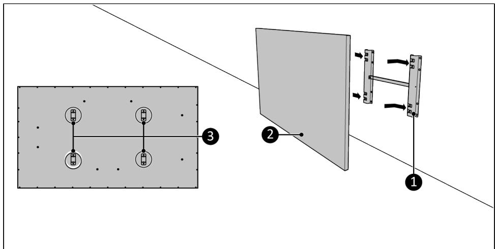
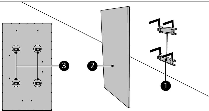
- Place the device brackets (Figure 35, pos. 3) over the wall bracket (Figure 35, pos. 1).
- Slide the device (Figure 35, pos. 2) into the openings of the wall bracket (Figure 35, pos. 1).
- Make sure the control panel is located at the bottom of the device.
- To remove the device, lift and slide it in the opposite direction.

Figure 34.

Figure 35.
Horizontal wall mounting
- Place the bracket against the wall, with the bracket openings at the left and mark the eight holes (Figure 36).
- Drill eight 10 mm holes at the marked spots.
- Place wall plugs (Figure 36, pos. 3).
- Screw and tighten the wall bracket (Figure 36, pos. 1) to the wall with eight large screws using a Phillips screwdriver (Figure 36, pos. 2).
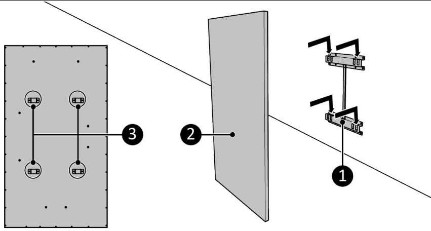
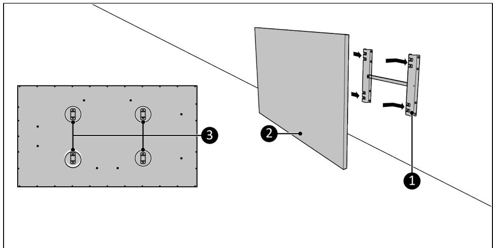
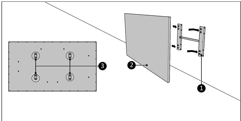
- Place the device brackets (Figure 37, pos. 3) over the wall bracket (Figure 37, pos. 1).
- Slide the device (Figure 37, pos. 2) into the openings of the wall bracket (Figure 37, pos. 1).
- Make sure the control panel is located at the topside of the device.
- To remove the device, lift and slide it in the opposite direction.

Figure 36.

Figure 37.
Mounting the pedestals

WARNING
The surface on which the device is placed must be made from non-flammable material and should be able to withstand a minimum temperature of 125 °C .

WARNING
Never place the device on surfaces such as beds or deep-pile carpet as openings could be blocked.

WARNING
Never use the device before it is correctly mounted. Be sure the control panel is on the topside when the device is used freestanding with the pedestals mounted.
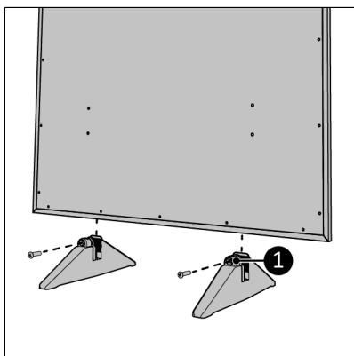
- Lay the device down on a steady, soft surface (Figure 38, pos. 2).
- Screw and tighten the pedestals (Figure 39, pos. 1).
- Place the device on a horizontal, solid and non-flammable surface.
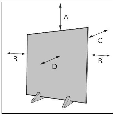
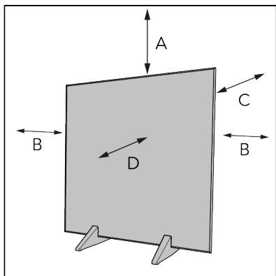
- Place the device with a minimum clearance distance (Figure 40) of:
A. 100 cm on the top side;
B. 50 cm on the sides;
C. 30 cm on the back side;
D. 50 cm on the front side. - Do not place the device immediately below a socket outlet.

Figure 38.

natural_image
Diagram of a flat-panel monitor with two stand holders and a numbered component (1), no text or symbols present.Figure 39.

Figure 40.
Ceiling mounting

CAUTION
When mounting the device to the ceiling, it is strongly recommended to use the Wi-Fi thermostat for optimal temperature control.

CAUTION
When mounting the device to the ceiling, it is absolutely necessary to calibrate the device panel. See chapter Temperature calibration (Optional) for explanation on the calibration function.
- Place the device on a non-flammable and solid ceiling.
- Place the device with a minimum distance (Figure 41) of:
A. 30 cm from the side walls; B. 185 cm from the floor. - Do not mount the device immediately over, near or below a socket outlet.
- Place the bracket against the ceiling and mark the eight holes (Figure 42).
- Drill eight 10 mm holes at the marked spots.
- Place wall plugs (Figure 42, pos. 3).
- Screw and tighten the bracket (Figure 42, pos. 1) to the ceiling with eight large screws using a Phillips screwdriver (Figure 42, pos. 2).
- Place the device brackets (Figure 43, pos. 3) over the ceiling bracket (Figure 43, pos. 1).
- Slide the device (Figure 43, pos. 2) into the openings of the ceiling bracket (Figure 43, pos. 1).
- Make sure the heater is properly secured in the ceiling bracket.
- To remove the device, lift and slide it in the opposite direction.
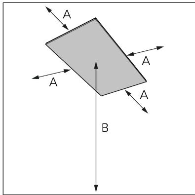
Figure 41.

Figure 42.

Figure 43.
Temperature sensor

CAUTION
For accurate temperature measuring use the external temperature sensor.
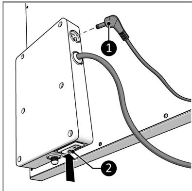
- Make sure the ON/OFF switch is in the OFF position (Figure 44, pos. 2).
- Connect the external temperature sensor connector (Figure 44, pos. 1) to the sensor plug.
- Place the temperature sensor approximately 2 meters away from the device.

Figure 44.
Installation

WARNING
- Do not put the power plug into the wall socket before the device is mounted or placed correctly.
- Do not use an extension cable; this can cause overheating and fire. If using an extension cable is unavoidable, make sure it is undamaged and earthed. Use an extension cable with a minimum power of 1000 Watt. Always unwind the extension cable completely to prevent overheating.

CAUTION
Make sure that the main voltage is the same as indicated on the identification label of the device. All electrical connections must stay dry under all circumstances.
- Make sure the device is correctly mounted.
- Make sure the ON/OFF switch is in the OFF position (Figure 45, pos. 2).
- Insert the power plug (Figure 45, pos. 1) into an earthed wall socket that is easily accessible. Use an earthed wall socket with a minimum power of 1000 Watt.
- Make sure the power cable does not come into contact with the device.

Figure 45.
Remote control
- Remove the battery cover (Figure 46, pos. 1).
- Insert two batteries (AAA 1.5 V) (Figure 46, pos. 2) as indicated in the battery compartment. Make sure to insert the batteries correctly.
- Replace the cover.
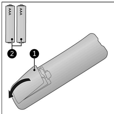
Figure 46.
Operation

WARNING
Before every use, make sure that:
- you operate the device with dry hands;
• the device is clean and dry;
• the device is not damaged; - the device is not covered or blocked;
- the device is securely mounted to the wall or ceiling.

CAUTION
When the device is turned on or off, it may emit a sound. This is the material expanding and shrinking during heating and cooling down.

CAUTION
The day and time settings will be reset to default if the device is switched off using the ON/OFF switch, is unplugged or is used without Wi-Fi connection.
If the device is used with the Eurom Smart App the time and day settings will automatically be correct.
- Set the ON/OFF switch to the ON position (Figure 47, pos. 3).
- Press the ON/OFF button on the control panel (Figure 47, pos. 2) or on the remote control.
- The display (Figure 47, pos. 1) will first show the set temperature for 3 seconds followed by the ambient temperature.

Figure 47.
Device control
Set the temperature
- Press the Plus or Minus button to set the desired temperature, from 0 °C to 45 °C.
- The device starts heating when the set temperature is higher than the ambient temperature and stops heating when the ambient temperature reaches the set temperature. The heating indicator will appear and disappear accordingly.
- The display shows the ambient temperature.
Set the day and time
(This is not needed when using the Eurom Smart App. If the device is used with the Eurom Smart App the time and day settings will automatically be correct.)
- Make sure the heating indicator is not visible. The device should not be heating.
- Press the Mode button, HH appears on the display.
- Press the Plus or Minus button to select the current day, from 1 (Monday) to 7 (Sunday).
- Press the Mode button, H1 appears on the display.
- Press the Plus or Minus button to select the current hour, from 0 to 23.
- Press the Mode button, H2 appears on the display.
- Press the Plus or Minus button to select the current minute, from 0 to 59.
- Press the Mode button, the ambient temperature appears on the display, the day and time are set.
Checking the day and time
- Make sure the heating indicator is visible, the device should be heating.
-
Press the Mode button briefly and repeatedly to check:
-
the day - HH;
- the hour - H1;
- the minutes - H2.
Remote control
The remote control should be directed towards the display in order to operate the device using the remote control.
Set the temperature
- Press the Plus or Minus button to set the desired temperature, from 0 °C to 45 °C.
- The device starts heating when the set temperature is higher than the ambient temperature and stops heating when the ambient temperature reaches the set temperature. The heating indicator will appear and disappear accordingly.
- The display shows the ambient temperature.
Set the day and time
- Make sure the heating indicator is not visible. The device should be ON but not heating.
- Press and hold the SET button until HH appears on the display.
- Press the Plus or Minus button to select the current day, from 1 (Monday) to 7 (Sunday).
- Press the SET button, H1 appears on the display.
- Press the Plus or Minus button to select the current hour, from 0 to 23.
- Press the SET button, H2 appears on the display.
- Press the Plus or Minus button to select the current minute, from 0 to 59.
- Press the SET button, the ambient temperature appears on the display, the day and time are set.
Check the day and time
- Make sure the heating indicator is visible, the device should be heating.
-
Press the SET button briefly and repeatedly to check:
-
the day – HH;
• the hour – H1; - the minutes – H2.
Open window detection
- Press the Open window detection button to activate. The Open window indicator appears on the display.
- When the ambient temperature decreases 5^ C or more within 15 minutes, the device will go in standby mode and the Open window indicator starts flashing on the display.
- Press the Open window detection button to deactivate.
ECO mode
The Eurom Smart App has an ECO button. ECO mode maintains the room temperature at 16°C.
- Press the ECO button to activate; EC appears on the screen.
- Press the ECO button to deactivate.
If the device is working in ECO mode and a timer setting becomes active, the device will start working according to the timer setting. When the timer setting ends, the device will not return to ECO mode.
Set the week timer
The week timer can be set via the remote control, but is easier to set using the Eurom Smart App. If in the week timer setting mode no button is pressed for ten seconds, it will reset and must start all over again. Make sure to not create any contradicting timer settings.
- Press and hold the WEEK button until UU appears and flashes on the display.
- Press the SET button; ON/OFF starts flashing on the display.
-
Press the Plus or Minus button to select:
-
ON – Timer on;
-
OFF – Timer off.
-
Press the OK button; UU appears on the display.
- Press the SET button.
-
Press the Plus or Minus button to select:
-
01 – all timer settings are executed once only. This can only be planned for the current week (U1 to U7). On Sunday (U7) at 23:59, all 01 timer settings are deleted;
-
99 – all timer settings are executed limitlessly.
-
Press the OK button; UU appears on the display.
-
Press the SET button; U1 appears on the display.
-
Press the Plus or Minus button to select the desired day, from U1 (Monday) to U7 (Sunday).
-
Press the OK button; the selected day appears on the display.
- Press the EDIT button; 01 appears on the display.
- Press the Plus or Minus button to select a number for this timer, from 1 to 4. Four means the maximum timer settings per day. If a new timer is set with the same number, the old timer will be overwritten.
- Press the OK button; the selected number appears on the display.
- Press the Temperature button; HP appears on the display.
-
Press the OK button; the selected temperature appears on the display.
-
Press the TIME ON button; HE appears on the display.
- Press the Plus or Minus button to select the desired start time, from 00:00 to 23:00 in whole hours.
- Press the OK button; the selected start time appears on the display.
- Press the TIME OFF button; HF appears on the display.
- Press the Plus or Minus button to select the desired stop time, from 00:00 to 23:00 in whole hours.
- Press the OK button; the selected stop time appears on the display.
- Repeat as desired.
Remove all week timer settings
- Press and hold the WEEK button until UU appears and flashes on the display.
- Press the Cancel button to erase all timer settings.
Remove all week timer settings for a specific day
- Press and hold the WEEK button until UU appears and flashes on the display.
- Press the SET button; ON/OFF appears on the display.
- Press the SET button; 01/99 appears on the display.
- Press the SET button; U1 appears on the display.
- Press the Plus or Minus button to select the desired day, from 1 (Monday) to 7 (Sunday).
- Press the Cancel button to erase all timer settings for the selected day.
Remove a specific timer setting
- Press and hold the WEEK button until UU appears and flashes on the display.
- Press the SET button; ON/OFF appears on the display.
- Press the SET button; 01/99 appears on the display.
- Press the SET button; U1 appears on the display.
- Press the Plus or Minus button to select the desired day, from 1 (Monday) to 7 (Sunday).
- Press the Edit button.
- Press the Plus or Minus button to select the desired timer setting, from 1 to 4.
- Press the Cancel button to erase the selected timer setting.
Check the timer settings
- Make sure the heating indicator is visible. The device should be heating.
-
Press the WEEK button briefly and repeatedly to check:
-
timer ON or timer OFF;
° once only (01) or endlessly (99); - U1-U7, day of the week;
- timer setting number of the day concerned (1, 2, 3 or 4);
- set temperature;
- start time in hours;
- stop time in hours;
- this is repeated for the next timer setting.
All 28 timer settings are shown, also the timer settings that have not been filled. The temperature of the non-filled timer settings is 20 °C .
Eurom Smart App

CAUTION
Do not use the weekly timer created with the device at the same time as the weekly timer created with the Eurom Smart App. Timer settings created by the Eurom Smart App are not visible on the device display. Timer settings created on the device are not visible in the Eurom Smart App.

CAUTION
It is recommended to switch on Bluetooth on your smart phone when connecting your Eurom device for the first time. Doing so will make connecting quicker and easier.
The device can be operated using an app on a smartphone or tablet. The Eurom Smart App can be used to:
- switch the device on and off;
• regulate the temperature.
The app can also be used to set twenty on and off timer settings daily, on the weekly timer.
- Open the Eurom Smart App manual with the QR code (Figure 48) or go to www.eurom.nl/nl/manuals.
-
Complete the steps in the Eurom Smart App manual.
-
When the device is connected with Wi-Fi, the Wi-Fi symbol appears on the screen.
- If the Wi-Fi symbol is blinking there is no connection.

Figure 48.
Smart Timer
-
Create a schedule with days and times in the Eurom Smart App. Timer settings set in the app:
-
will be stored on the device;
- will not be visible on the device;
- will remain available if Wi-Fi disconnects;
- will remain available if the device is switched off or unplugged;
-
can only be removed via the app.
-
Check the data in the app regularly.
Reset Wi-Fi connection
- Press and hold the Mode button until a beep sounds. Existing connections will be deleted. The Wi-Fi symbol will start blinking and a new connection can be made.
Switch off Wi-Fi connection
- Verify that the heating indicator is not visible. The device should be on but not heating.
- Press and hold the ON/OFF button until a beep sounds. The Wi-Fi is switched off and the Wi-Fi symbol will disappear from the screen.
- Press and hold the ON/OFF button until a beep sounds. The Wi-Fi is switched on and the Wi-Fi symbol will appear on the screen.
Wi-Fi thermostat ready (Optional)
This device can be connected with the optional Wi-Fi thermostat. The temperature is measured at the Wi-Fi thermostat instead of the device. This ensures an optimized comfort level. The device will keep heating until the set temperature of the Wi-Fi thermostat is reached.
It is possible to connect multiple devices to a single Wi-Fi thermostat. All the connected devices will switch on and off simultaneously.
To use the Wi-Fi thermostat:
- Place the Wi-Fi thermostat in any power socket.
- Download the Eurom Smart App on a (mobile) device.
- Open the Eurom Smart App.
- Add the Wi-Fi thermostat and other devices to the Eurom Smart App.
- Go to the device(s) and press the Pairing Button to pair the device(s) to the Wi-Fi thermostat.
The device is connected to the Wi-Fi Thermostat. The G-sign illuminates in the Eurom Smart app and on the device. Now you can enjoy the optimized comfort level of permanent electric heating.
Temperature calibration (Optional)

CAUTION
When the device is mounted on the ceiling, the internal temperature sensor is not able to measure the temperature in the room correctly as heat rises. Therefore, it is absolutely necessary to calibrate the device panel when it is mounted on the ceiling.
Calibrating the device
- Set the desired temperature to 45^ C (max. temperature).
- Let the device heat without interruptions for 120 minutes.
- Place a digital room thermometer (not included) at a central place where the desired temperature should be achieved; recommended is 150 cm from the floor.
- After 120 minutes, calculate the difference between the external thermometer and the temperature shown on the display of the heater (press any button to reappear). For example: if the display shows 34 °C and the thermometer 20 °C , then the calibration can be
calculated as follows: 34 (temperature display) minus 20 (temperature thermometer) plus 10 (standard correction) = 24.
- Press the Calibration button on the remote control; a number appears on the display.
- Press the Plus or Minus button to select the calibration number, from 00 to 28. In our example this is 24.
- Press the OK button.
- Set the ON/OFF switch to the OFF position (Figure 45, pos. 2) to activate the calibration process.
Calibration mode
- Every time the device is turned on and starts heating, the calibration process will be started. The device display will show CL and the Eurom Smart App will show Calibration in progress. The calibration process uses the calibration number to gradually adjust the measured temperature to the calibrated room temperature. This can take up to 80 minutes.
When the calibration is ready the display and the Eurom Smart App will show the calibrated room temperature. When the calibration value is correctly measured the calibrated room temperature will be approximately the same as the real room temperature.
- When the heater stops heating, the calibration process will start in opposite direction (cooling calibration). The device display will show CL and the Eurom Smart App will show Calibration in progress. The cooling calibration process can take up to 110 minutes.
- Do not switch off the heater during a calibration process, breaking off the calibration process will cause a temporary difference between the calibrated room temperature and the real room temperature. In this case the heater will not heat up to the temperature you have set. If by accident the calibration process is cancelled, the difference will resolve itself over time.
For ceiling-mounted use it is recommended to use the Eurom Wi-Fi thermostat (365764, 365771 (Swiss plug) & 365788 (USB-C)) for optimal temperature control. The Wi-Fi thermostat measures the room temperature and communicates the information via Wi-Fi to the device.
After operation

CAUTION
Do not use the power cable to unplug or carry the device. Do not wind the power cable too tightly or in sharp corners. Do not wrap the power cable around the device.
- Make sure the ON/OFF switch is in the OFF position (Figure 45, pos. 2).
- Disconnect the power plug from the power outlet.
- Let the device cool down before touching it.
- Wind the power cable.
- Remove the batteries from the remote control (Figure 46).
Maintenance

WARNING
Do not perform any repairs or modifications to this device.
Maintenance and repairs must be carried out by a EUROM authorized professional. If the electric cable and/or electric plug is damaged, it should be replaced by the manufacturer or its service employee or persons with similar qualifications to prevent risks.
Cleaning

CAUTION
Do not use:
- scouring pads;
- hard brushes;
- flammable, aggressive or chemical cleaning products.
Prevent water from entering the device. Do not immerse any part of the device in water or other liquids.
It is recommended to clean the device after each use and prior to storage.
- Wipe the device with a damp, clean, soft, lint-free cloth or a soft brush.
- Let the device dry completely prior to use and storage.
Disposal

natural_image
Two black-and-white symbols: a trash can crossed out by a crossed-out line and a recycling symbol (no text or labels)This marking indicates that this product should not be disposed of with other household waste throughout the EU. To prevent possible harm to the environment or human health from uncontrolled waste disposal, recycle it responsibly to promote the sustainable reuse of material resources. To return your used device, please use the return and collection systems or contact the retailer where the product was purchased. They can take this product for environmentally safe recycling.
Attachments
| Information requirement for the electric local space heaters | |||||
| Model identifier: Mon Soleil Frame 360 Wi-Fi | |||||
| Item | Symbol | Value | Unit | Item | Unit |
| Heat output | Type of heat output/room temperature control (select one) | ||||
| Nominal heat output | Pnom | 0,360 | kW | single stage heat output and no room temperature control | no |
| Minimum heat output (indicative) | Pmin | N.A. | kW | two or more manual stages, no room temperature control | no |
| Maximum continuous heat output | Pmax,c | 0,355 | kW | with mechanic thermostat room temperature control | no |
| Power consumption | with electronic room temperature control | no | |||
| In off mode | Po | N.A. | W | electronic room temperature control plus day timer | no |
| In standby mode | Psm | 0,28 | W | electronic room temperature control plus week timer | yes |
| In idle mode | Pidle | 0,28 | W | Other control options (multiple selections possible) | |
| In network standby | Pnsm | 0,60 | W | room temperature control, with presence detection | no |
| Standby mode with display of information or status | yes | room temperature control, with open window detection | yes | ||
| Seasonal space heating energy efficiency in active mode | ηS,on | 94,0 | % | distance control option | yes |
| adaptive start control | no | ||||
| working time limitation | yes | ||||
| black bulb sensor | no | ||||
| self-learning functionality | no | ||||
| control accuracy | no | ||||
| Contact details | Eurom - Kokosstraat 20 - 8281 JC - Genemuiden - The Netherlands | ||||
| Model identifier: Mon Soleil Frame 600 Wi-Fi | |||||
| Item | Symbol | Value | Unit | Item | Unit |
| Heat output | Type of heat output/room temperature control (select one) | ||||
| Nominal heat output | Pnom | 0,600 | kW | single stage heat output and no room temperature control | no |
| Minimum heat output (indicative) | Pmin | N.A. | kW | two or more manual stages, no room temperature control | no |
| Maximum continuous heat output | Pmax,c | 0,578 | kW | with mechanic thermostat room temperature control | no |
| Power consumption | with electronic room temperature control | no | |||
| In off mode | Po | N.A. | W | electronic room temperature control plus day timer | no |
| In standby mode | Psm | 0,28 | W | electronic room temperature control plus week timer | yes |
| In idle mode | Pidle | 0,28 | W | Other control options (multiple selections possible) | |
| In network standby | Pnsm | 0,60 | W | room temperature control, with presence detection | no |
| Standby mode with display of information or status | yes | room temperature control, with open window detection | yes | ||
| Seasonal space heating energy efficiency in active mode | ηS,on | 94,0 | % | distance control option | yes |
| adaptive start control | no | ||||
| working time limitation | yes | ||||
| black bulb sensor | no | ||||
| self-learning functionality | no | ||||
| control accuracy | no | ||||
| Contact details | Eurom - Kokosstraat 20 - 8281 JC - Genemuiden - The Netherlands | ||||
| Model identifier: Mon Soleil Frame 720 Wi-Fi | |||||
| Item | Symbol | Value | Unit | Item | Unit |
| Heat output | Type of heat output/room temperature control (select one) | ||||
| Nominal heat output | Pnom | 0,720 | kW | single stage heat output and no room temperature control | no |
| Minimum heat output (indicative) | Pmin | N.A. | kW | two or more manual stages, no room temperature control | no |
| Maximum continuous heat output | Pmax,c | 0,685 | kW | with mechanic thermostat room temperature control | no |
| Power consumption | with electronic room temperature control | no | |||
| In off mode | Po | N.A. | W | electronic room temperature control plus day timer | no |
| In standby mode | Psm | 0,28 | W | electronic room temperature control plus week timer | yes |
| In idle mode | Pidle | 0,28 | W | Other control options (multiple selections possible) | |
| In network standby | Pnsm | 0,60 | W | room temperature control, with presence detection | no |
| Standby mode with display of information or status | yes | room temperature control, with open window detection | yes | ||
| Seasonal space heating energy efficiency in active mode | ηS,on | 94,0 | % | distance control option | yes |
| adaptive start control | no | ||||
| working time limitation | yes | ||||
| black bulb sensor | no | ||||
| self-learning functionality | no | ||||
| control accuracy | no | ||||
| Contact details | Eurom - Kokosstraat 20 - 8281 JC - Genemuiden - The Netherlands | ||||
Abbildung 51.
Abbildung 56.
Abbildung 57.
Vertikale Wandmontage
Abbildung 58.

Abbildung 59.
Horizontale Wandmontage
Abbildung 60.
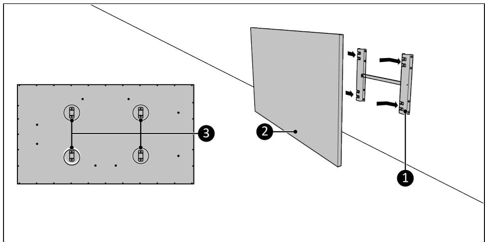
Abbildung 61.
Montage der Sockel

WARNUNG
Abbildung 62.

natural_image
Diagram of a flat-panel monitor mounted on two triangular supports, with no visible text or symbolsAbbildung 63.

Abbildung 64.
Deckenmontage

VORSICHT
Abbildung 66.

flowchart
graph TD
    A[" "] --> B[" "]
    C[" "] --> D[" "]
    E[" "] --> F[" "]
    G[" "] --> H[" "]
    I[" "] --> J[" "]
    K[" "] --> L[" "]
    M[" "] --> N[" "]
    O[" "] --> P[" "]
    Q[" "] --> R[" "]
    S[" "] --> T[" "]
    U[" "] --> V[" "]
    W[" "] --> X[" "]
    Y[" "] --> Z[" "]
    AA[" "] --> AB[" "]
    AC[" "] --> AD[" "]
    AE[" "] --> AF[" "]
    AG[" "] --> AH[" "]
    AI[" "] --> AJ[" "]
    AK[" "] --> AL[" "]
    AM[" "] --> AN[" "]
    AO[" "] --> AP[" "]
    AQ[" "] --> AR[" "]
    AS[" "] --> AT[" "]
    AU[" "] --> AV[" "]
    AW[" "] --> AX[" "]
    AY[" "] --> AB
    AZ[" "] --> AV
    BA[" "] --> AW
    BB[" "] --> AX
    BC[" "] --> AV
    BD[" "] --> AW
    BE[" "] --> AX
    BF[" "] --> AV
    BG[" "] --> AW
    BH[" "] --> AX
    BI[" "] --> AV
    BJ[" "] --> AW
    BK[" "] --> AX
    BL[" "] --> AV
    BM[" "] --> AW
    BN[" "] --> AX
    BO[" "] --> AV
    BP[" "] --> AW
    BQ[" "] --> AX
    BR[" "] --> AV
    BS[" "] --> AW
    BT[" "] --> AX
    BU[" "] --> AV
    BV[" "] --> AW
    BW[" "] --> AX
    BX[" "] --> AV
    BY[" "] --> AW
    BZ[" "] --> AX
    CA[" "] --> AV
    CB[" "] --> AW
    CC[" "] --> AX
    CD[" "] --> AV
    CE[" "] --> AW
    CF[" "] --> AX
    CG[" "] --> AV
    CH[" "] --> AW
    CI[" "] --> AX
    CJ[" "] --> AV
    CK[" "] --> AW
    CL[" "] --> AX
    CM[" "] --> AV
    CN[" "] --> AW
    CO[" "] --> AX
    CP[" "] --> AV
    CE1["3"] -.-> A2

Abbildung 67.
Temperatursensor

VORSICHT
Abbildung 68.
Installation

WARNUNG
Abbildung 69.
Fernbedienung
Abbildung 70.
Betrieb

WARNUNG
Abbildung 71.
Gerätesteuerung
Abbildung 72.
Intelligenter Timer
natural_image
Two black-and-white symbols: a trash can crossed out by a crossed-out line and a recycling symbol (no text or labels)Figure 75.
Assembler le support
Figure 80.
Figure 81.
Montage mural vertical
Figure 82.
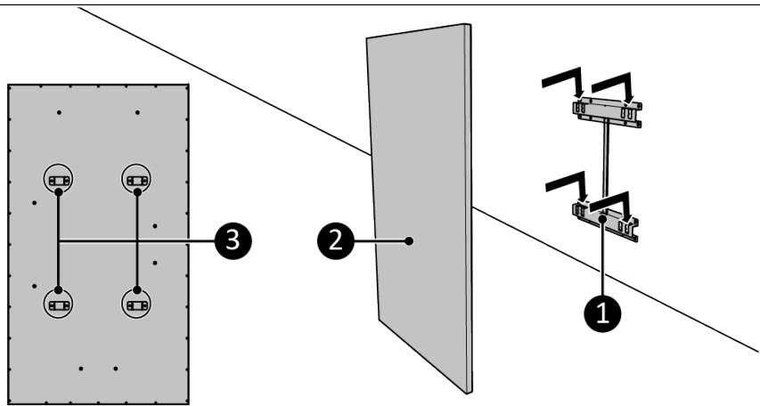
Figure 83.
Montage mural horizontal
Figure 84.
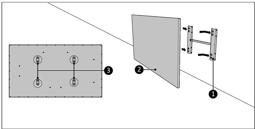
Figure 85.
Monter les socles

AVERTISSEMENT
Figure 86.

natural_image
Diagram of a flat-panel monitor with two triangular supports and a numbered label (1), no text or symbols present.Figure 87.
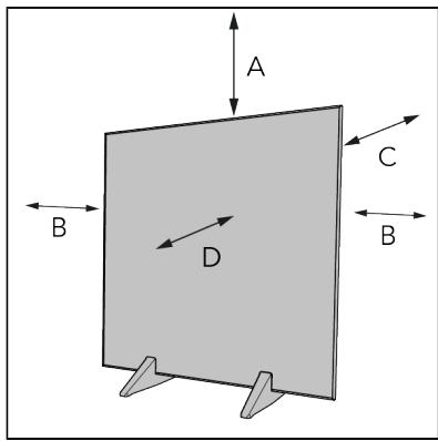
Figure 88.
Montage au plafond

PRUDENCE
Figure 90.

Figure 91.
Figure 92.
Installation

AVERTISSEMENT
Figure 93.
Télécommande
Figure 94.
Utilisation

AVERTISSEMENT
Figure 95.
Figure 96.
Minuterie intelligente
natural_image
Two black recycling symbols: a crossed-out trash bin and a solid recycling triangle (no text or labels)Figur 99.
Figur 100.
Figur 104.
Figur 105.
Figur 106.
Figur 107.
Figur 108.

Figur 109.
Montering på piedestaler

WARNING
Figur 110.

natural_image
Diagram of a flat-panel monitor with two triangular supports and a numbered label (1) indicating a component, no text or symbols present.Figur 111.
Figur 112.
Innertaksmontering

FÖRSIKTIGHET
Figur 114.

Figur 115.
Temperaturgivare

FÖRSIKTIGHET
Figur 116.
Installation

WARNING
Figur 117.
Fjärrstyrning
Figur 118.
Drift

WARNING
Figur 119.
Enhetsstyrning
Ställ in temperaturen
Figur 120.
Smart timer
Figur 123.
Figur 124.
Kontrolpanel og LED-display
- Skærm
- Strømindikation
- Indikator for Wi-Fi-termostat
- Indikator for Wi-Fi
- Åbent vindue-indikator
- Indikator for varme
- Minusknap
- Plusknap
- Mode-knap
- ON/OFF-knap
Figur 125.
Fjernbetjening

OBS
Figur 128.
Figur 129.
Lodret vægmontering
Figur 130.

Figur 131.
Figur 132.
Figur 133.
Figur 134.
natural_image
Diagram of a flat-panel monitor with two base mount supports and a numbered component (no text or symbols)Figur 135.

Figur 136.
Loftsmontering

FORSIGTIG
Figur 138.

Figur 139.
Temperatursensor

FORSIGTIG
Brug den eksterne temperatursensor for at opnå en nøjagtig temperaturmåling.
- Sørg for, at ON/OFF-kontakten er i OFF-position (Figur 140, pos. 2).
- Tilslut temperatursensorens stik (Figur 140, pos. 1) til sensorstikket.
- Placer temperatursensoren ca. 2 meter væk fra enheden.
Figur 140.
Installation

ADVARSEL
Figur 141.
Fjernbetjening
Figur 142.
Betjening

ADVARSEL
Figur 143.
Enhedsstyring
Indstil temperatur
Figur 144.
Smart Timer
natural_image
Two black recycling symbols: a trash bin crossed out and a recycling symbol (no text or labels)Obrázek 147.
Obrázek 148.
Obrázek 152.
Obrázek 153.
Obrázek 154.
Obrázek 155.
Obrázek 156.
Obrázek 157.
Montáž na nožkách

Varování
Obrázek 158.

natural_image
Diagram of a flat-panel monitor mounted on two triangular supports, with no visible text or symbolsObrázek 159.

Obrázek 160.
Umístění na strop

UPOZORNĚNÍ
Obrázek 162.

Obrázek 163.
Snímač teploty

Upozornění
Obrázek 164.
Instalace

Varování
Obrázek 165.
Dálkové ovládání
Obrázek 166.
Provoz

Varování
Obrázek 167.
Ovládání zařízení
Nastavení teploty
Obrázek 168.
Chytrý časovač
Obrázok 171.
Obrázok 172.
Obrázok 176.
Obrázok 177.
Obrázok 178.

Obrázok 179.
Obrázok 180.
Obrázok 181.
Montáž podstavcov

UPOZORNENIE
Obrázok 182.

natural_image
Diagram of a flat-panel monitor with two stand holders and a numbered label (1) indicating a component, no text or symbols present.Obrázok 183.

Obrázok 184.
Montáž na strop

VÝSTRAHA
Obrázok 186.

flowchart
graph TD
    A["Node 1"] --> B["Node 2"]
    C["Node 3"] --> D["Node 4"]
    style A fill:#fff,stroke:#000
    style B fill:#fff,stroke:#000
    style C fill:#fff,stroke:#000
    style D fill:#fff,stroke:#000

Obrázok 187.
Snímač teploty

VÝSTRAHA
Obrázok 188.

UPOZORNENIE
Obrázok 189.
Dial'kový ovládač
Obrázok 190.
Prevádzka

UPOZORNENIE
Obrázok 191.
Obrázok 192.
natural_image
Two black recycling symbols: a crossed-out trash bin and a solid recycling triangle (no text or labels)Figura 195.
Figura 196.
Figura 200.
Figura 201.
Figura 202.

Figura 203.
Figura 204.

Figura 205.
Figura 206.

natural_image
Diagram of a flat-panel monitor with two base mount supports and a numbered component (no text or symbols)Figura 207.

Figura 208.
Montarea pe tavan

ATENTIE
Figura 210.
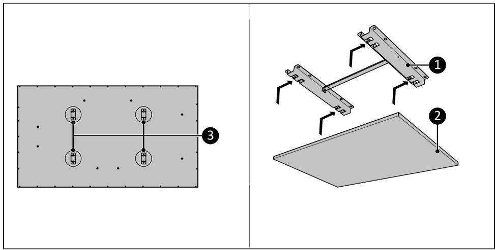
Figura 211.
Figura 212.
Instalare

AVERTISMENT
Figura 213.
Telecomandă
Figura 214.
Functionare

AVERTISMENT
Figura 215.
Comandă dispozitiv
Setarea temperaturii
Figura 216.
Temporizator intelligent
natural_image
Two black-and-white symbols: a recycling can crossed out by a horizontal line and a recycling triangle (no text or labels)
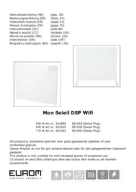
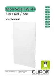
- Mon Soleil Frame Wi-Fi
- Bedieningspaneel en leddisplay
- Afstandsbediening
- Verticale wandmontage
- Horizontale wandmontage
- De voetjes monteren
- WAARSCHUWING
- Temperatuursensor
- LET OP
- Installatie
- Werking
- Apparaatbediening
- Temperatuurinstelling
- Slimme timer
- WARNING
- CAUTION
- General safety instructions
- Safety during operation
- Warranty
- Introduction
- Identification
- Description
- Overview
- Control panel and LED display
- Remote control
- ATTENTION
- Transport and storage
- Assembly
- Mounting
- Wall mounting
- Assembling the bracket
- Vertical wall mounting
- Horizontal wall mounting
- Mounting the pedestals
- Ceiling mounting
- Temperature sensor
- Installation
- Operation
- Device control
- Set the temperature
- Set the day and time
- Checking the day and time
- Check the day and time
- Open window detection
- ECO mode
- Set the week timer
- Remove all week timer settings
- Remove all week timer settings for a specific day
- Remove a specific timer setting
- Check the timer settings
- Eurom Smart App
- Smart Timer
- Reset Wi-Fi connection
- Switch off Wi-Fi connection
- Wi-Fi thermostat ready (Optional)
- Temperature calibration (Optional)
- Calibrating the device
- Calibration mode
- After operation
- Maintenance
- Cleaning
- Vertikale Wandmontage
- Montage der Sockel
- WARNUNG
- Deckenmontage
- VORSICHT
- Temperatursensor
- Fernbedienung
- Betrieb
- Gerätesteuerung
- Intelligenter Timer
- Assembler le support
- Montage mural vertical
- Montage mural horizontal
- Monter les socles
- AVERTISSEMENT
- Montage au plafond
- PRUDENCE
- Télécommande
- Utilisation
- Minuterie intelligente
- Montering på piedestaler
- Innertaksmontering
- FÖRSIKTIGHET
- Temperaturgivare
- Fjärrstyrning
- Drift
- Enhetsstyrning
- Ställ in temperaturen
- Kontrolpanel og LED-display
- Fjernbetjening
- Lodret vægmontering
- Loftsmontering
- FORSIGTIG
- ADVARSEL
- Betjening
- Enhedsstyring
- Indstil temperatur
- Montáž na nožkách
- Varování
- Umístění na strop
- UPOZORNĚNÍ
- Snímač teploty
- Instalace
- Dálkové ovládání
- Provoz
- Ovládání zařízení
- Nastavení teploty
- Chytrý časovač
- Montáž podstavcov
- UPOZORNENIE
- Montáž na strop
- VÝSTRAHA
- Dial'kový ovládač
- Prevádzka
- Montarea pe tavan
- ATENTIE
- Instalare
- AVERTISMENT
- Telecomandă
- Functionare
- Comandă dispozitiv
- Setarea temperaturii
- Temporizator intelligent
Brand : Eurom
Model : Mon Soleil Frame Wi-Fi
Category : Electric heater