ST 440 - Jigsaw AEG - Free user manual and instructions
Find the device manual for free ST 440 AEG in PDF.
| Product type | Jigsaw |
| Brand | AEG |
| Model | ST 440 |
| Power consumption | 440 W |
| No-load stroke rate | 3000 min-1 |
| Stroke height | 19 mm |
| Max. cutting depth (softwood) | 60 mm |
| Max. cutting depth (wood) | 50 mm |
| Max. cutting depth (steel) | 3 mm |
| Max. cutting depth (aluminum) | 10 mm |
| Bevel cut | Up to 45° |
| Weight | 1.6 kg |
| Power supply | Single-phase, voltage according to rating plate |
| Double insulation | Yes (according to DIN 57 740 / VDE 0740 and CEE 20) |
| Anti-interference | According to EN 55014 |
| Noise level | 82 dB(A) (actual); may exceed 85 dB(A) |
| Vibration (actual acceleration) | 3 m/s² |
| Pendulum action | No (ST 440 model without pendulum adjustment) |
| Stroke rate adjustment | No (ST 440 model without adjustment) |
| Chip extraction system | Integrated, inner diameter 30 mm |
| Splinter guard | Accessory available |
| Parallel guide / Circle guide | Accessory available |
| Synthetic material sole | Accessory for sensitive surfaces |
| Recommended maintenance | Annual check of brushes (carbon) at AEG after-sales service |
| Warranty and repairability | AEG parts and accessories; service center address in brochure |
Frequently Asked Questions - ST 440 AEG
User questions about ST 440 AEG
0 question about this device. Answer the ones you know or ask your own.
Ask a new question about this device
Download the instructions for your Jigsaw in PDF format for free! Find your manual ST 440 - AEG and take your electronic device back in hand. On this page are published all the documents necessary for the use of your device. ST 440 by AEG.
USER MANUAL ST 440 AEG
ST 400
ST 440
STEP 420
STEP 450
SPE 70
SPE 80 A
GB Instructions for use Please read and save these instructions.
D Gebrauchsanleitung Bittle lesen und aufbewahren.
F Instruction d'utilisation Priere de dire et de conserver.
Istruzioni d'uso Si prega di leggere le istruzioni e di conservare.
E Instrucciones de uso Leay conserve estas instrucciones porfavor.
P Instruções de service Por favor leia e conserve em seu poder.
NL Gebruiksaanwijzing Lees en let goed op deze adviezen.
DK Brugsanvisning Vær venlight at læse og opbevare.
s Bruksanvising Var god Ias och tag tillvara dessa instruktioner.
FIN Käyttoohje Lue ja sāilytö
| Introduction | You have high standards and expect to purchase quality goods - quality offered by Atlas Copco. We have built a durable and reliable electric power tool for you. Please read the instructions for use before first operation so you can handle your power tool effectively and safely. We are sure that buying an AEG Electric Power Tool from Atlas Copco was the right choice! |
| Technical Data | ST 400 ST 440 STEP 420 Cutting depth max. in: Soft- wood 60 mm 60 mm 65 mm Hard-wood 50 mm 50 mm 55 mm Steel 3 mm 3 mm 5 mm Aluminium 10 mm 10 mm 10 mm Nominal power 400 W 440 W 420 W Weight 1,6 kg 1,6 kg 1,7 kg Stroke rate under no-load 3000 min-1 3000 min-1 450-3000 min-1 Lengths of stroke 19 mm 19 mm 19 mm Bevel cuts up to 45° 45° 45° 45° STEP 450 SPE 70 SPE 80 A Cutting depth max. in: Soft- wood 65 mm 70 mm 70 mm Hard-wood 55 mm 60 mm 60 mm Steel 5 mm 5 mm 5 mm Aluminium 10 mm 10 mm 10 mm Nominal power 450 W 500 W 500 W Weight 1,7 kg 1,7 kg 1,7 kg Stroke rate under no-load 450-3000 min-1 450-3000 min-1 Lengths of stroke 19 mm 19 mm 19 mm Bevel cuts up to 45° 45° 45° 45° |
| Advice for your safety | Please pay attention to the safety instructions in the attached leaflet! Dust that arises when working on material containing asbestos or stonework containing crystalline silicic acid is harmful to the health. Please follow accident prevention regulations. Appliances used at many different locations including open air must be connected via a current surge preventing switch. Always use the protective shields on the machine. Always disconnect the plug from the socket before carrying out any work on the machine. Always wear goggles when using the machine. It is recommended to wear gloves, sturdy non slipping shoes and apron. Sawdust and splinters must not be removed while the machine is running. Do not pierce the motor housing as this could damage the double insulation (use adhesives). Keep mains lead clear from working range of the machine. Always lead the cable away behind you. Only plug-in when machine is switched off. Dust that arises when working on wood or using the tool on industrial material can be dangerous to health. In this case connect the tool to a suitable suction device. Do not use cracked or distorted saw blades. |
| Measured sound value | Typically the A-weighted sound pressure level of the tool is 82 dB (A). The noise level when working can exceed 85 dB (A). Wear ear protectors! Measured values determined according to EN 50 144. |
| Measured vibration value | Typically the weighted acceleration is 3 m/s2. Measured values determined according to EN 50 144. |
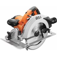
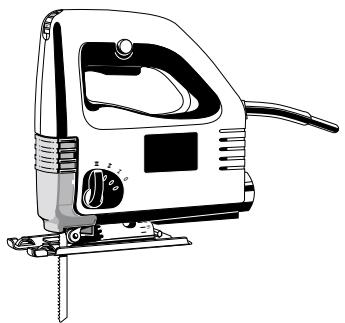
| Use | This jig saw can cut wood, plastic and metal; it can cut straight lines, bevels, curves, and internal cut-outs. Do not use this product in another way as stated for normal use. |
| ENGLISH | 1 ST 400, ST 440, STEP 420, STEP 450, SPE 70, SPE 80 A |
Mains connection
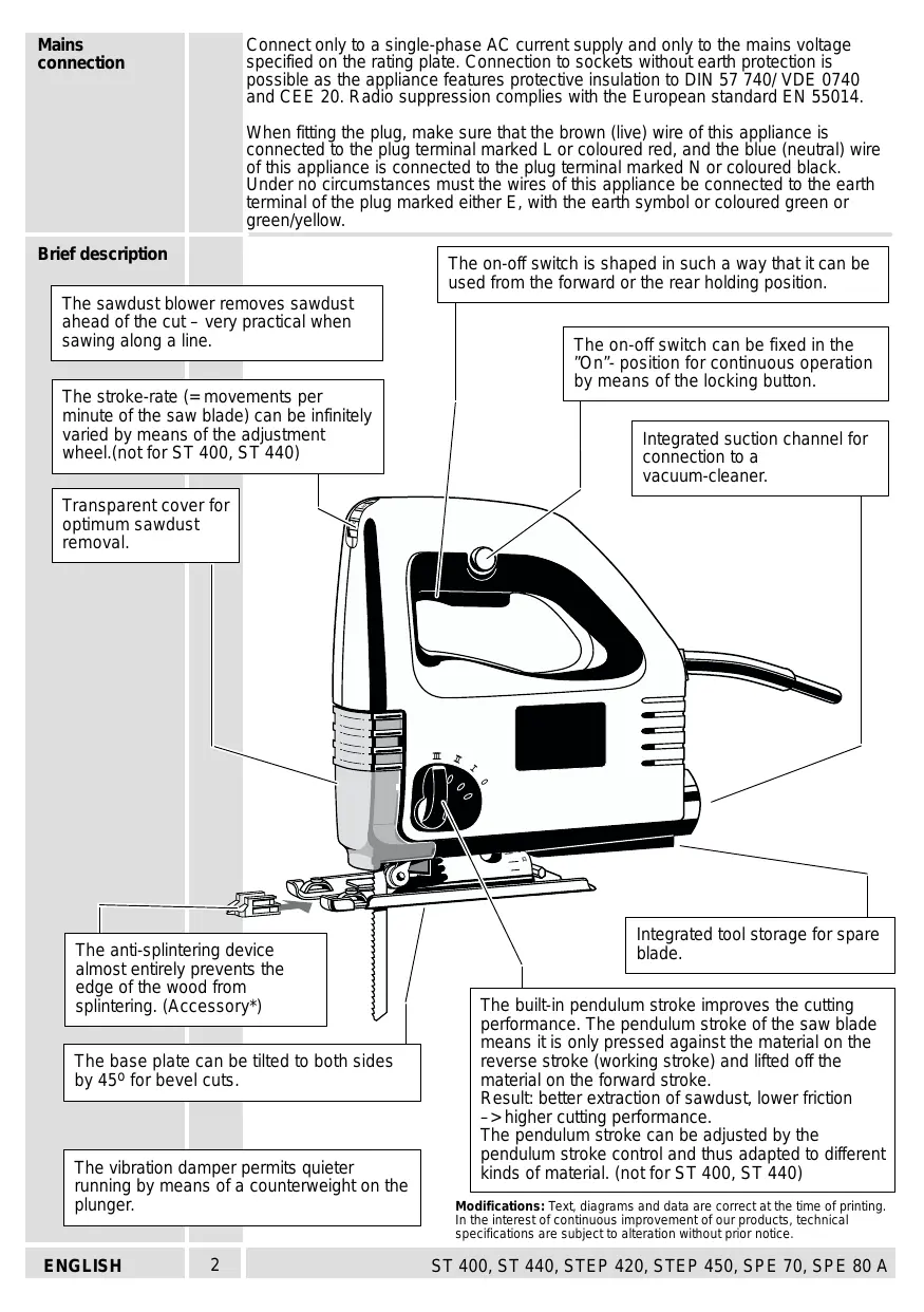
Connect only to a single-phase AC current supply and only to the mains voltage specified on the rating plate. Connection to sockets without earth protection is possible as the appliance features protective insulation to DIN 57 740/ VDE 0740 and CEE 20. Radio suppression complies with the European standard EN 55014.
When fitting the plug, make sure that the brown (live) wire of this appliance is connected to the plug terminal marked L or coloured red, and the blue (neutral) wire of this appliance is connected to the plug terminal marked N or coloured black. Under no circumstances must the wires of this appliance be connected to the earth terminal of the plug marked either E, with the earth symbol or coloured green or green/yellow.
Brief description
The sawdust blower removes sawdust ahead of the cut - very practical when sawing along a line.
The stroke-rate (= movements per minute of the saw blade) can be infinitely varied by means of the adjustment wheel.(not for ST 400, ST 440)
Transparent cover for optimum sawdust removal.
The anti-splintering device almost entirely prevents the edge of the wood from splintering. (Accessory*)
The base plate can be tilted to both sides by 45^ for bevel cuts.
The vibration damper permits quieter running by means of a counterweight on the plunger.
The on-off switch is shaped in such a way that it can be used from the forward or the rear holding position.
The on-off switch can be fixed in the "On"- position for continuous operation by means of the locking button.
Integrated suction channel for connection to a vacuum-cleaner.
Integrated tool storage for spare blade.
The built-in pendulum stroke improves the cutting performance. The pendulum stroke of the saw blade means it is only pressed against the material on the reverse stroke (working stroke) and lifted off the material on the forward stroke.
Result: better extraction of sawdust, lower friction higher cutting performance.
The pendulum stroke can be adjusted by the pendulum stroke control and thus adapted to different kinds of material. (not for ST 400, ST 440)
Modifications: Text, diagrams and data are correct at the time of printing. In the interest of continuous improvement of our products, technical specifications are subject to alteration without prior notice.
EC-DECLARATION OF CONFORMITY
We declare under our sole responsibility that this product is in conformity with the following standards or standardized documents. EN 50144, EN 55014-1, EN 55014-2, EN 61000-3-2, EN 61000-3-3, in accordance with the regulations 98/37/EC, 73/23/EEC, 89/336/EEC
DEUTSCH
DECLARATION "CE" DE CONFORMITÉ
CE-KONFORMITETSERKL/ERING
Manager Product Marketing and Development


Copyright 2000
Atlas Copco Electric Tools GmbH
P.O.Box 320
D-71361 Winnenden Germany
www.atlascopco.de