BLACK & DECKER KG 725 - Power tool BLACK & DECKER - Free user manual and instructions
Find the device manual for free BLACK & DECKER KG 725 BLACK & DECKER in PDF.

| Product Type | Angle grinder |
| Brand | Black & Decker |
| Model | KG 725 (KG75) |
| Rated voltage | 230 V AC |
| Power input | 750 W |
| No-load speed | 10 000 min⁻¹ |
| Disc diameter | 115 mm |
| Disc bore | 22 mm |
| Shaft size | M14 |
| Weight | 2.4 kg |
| Main functions | Grinding, cutting, sanding |
| Compatible materials | Metal, concrete, wood (with accessories) |
| Double insulation | Yes (class II) |
| Sound pressure level (LpA) | 89.9 dB(A) |
| Sound power level (LwA) | 102.9 dB(A) |
| Vibration level (hand/arm) | < 2.5 m/s² |
| Safety | Protective guard, spindle lock, on/off switch |
| Box contents | Angle grinder, side handle, flange set, two-pin spanner, manual |
| Maintenance and cleaning | Clean ventilation slots with a soft brush; clean guard with a damp cloth |
| Warranty | 24 months |
| Intended use | Household use only |
Frequently Asked Questions - BLACK & DECKER KG 725 BLACK & DECKER
User questions about BLACK & DECKER KG 725 BLACK & DECKER
0 question about this device. Answer the ones you know or ask your own.
Ask a new question about this device
Download the instructions for your Power tool in PDF format for free! Find your manual BLACK & DECKER KG 725 - BLACK & DECKER and take your electronic device back in hand. On this page are published all the documents necessary for the use of your device. BLACK & DECKER KG 725 by BLACK & DECKER.
USER MANUAL BLACK & DECKER KG 725 BLACK & DECKER
You have chosen a Black & Decker tool. Our aim is to provide quality tools at an affordable price. We hope that you will enjoy using this tool for many years.
EC DECLARATION OF CONFORMITY

KG68/KG70/KG75/CD500
Black & Decker declares that these products conform to: 98/37/EC, 89/336/EEC, 73/23/EEC, EN 50144, EN 55014, EN 61000
Level of sound pressure, measured according to EN 50144:
| LpA (sound pressure) | dB(A) | 89.9 |
| LwA (acoustic power) | dB(A) | 102.9 |

Always wear ear protection if the sound pressure exceeds 85 dB(A).
Hand/arm weighted vibration value according to EN 50144:
<2.5 m/s²

Brian Cooke
Director of Engineering
Spennymoor, County Durham DL16 6JG, United Kingdom
INTENDED USE
Your Black & Decker angle grinder has been designed for cutting metal and masonry using the appropriate type of cutting or grinding disc. It is also suitable for sanding using a backing pad and sanding disc.
This tool is intended for consumer use only.
SAFETY INSTRUCTIONS
Warning symbols
The following symbols are used in this manual:

Denotes risk of personal injury, loss of life or damage to the tool in case of non-observation of the instructions in this manual.

Denotes risk of electric shock.

Read the manual prior to operation.

Fire hazard.
Know your tool

Warning! When using mains-powered tools, basic safety precautions, including the following, should always be followed to reduce the risk of fire, electric shock, personal injury and material damage.
Read all of this manual carefully before operating the tool.
Before operating the tool, make sure that you know how to switch the tool off in an emergency.
Retain this manual for future reference.
6
SAG.P65
6
17-07-2001, 14:51
ENGLISH
General
1. Keep work area clean
Cluttered areas and benches can cause accidents.
2. Consider work area environment
Do not expose the tool to rain. Do not use the tool in damp or wet conditions. Keep the work area well lit. Do not use the tool where there is a risk of causing fire or explosion, e.g. in the presence of flammable liquids and gases.
3. Keep children away
Do not allow children, visitors or animals to come near the work area or to touch the tool or mains cable.
4. Dress properly
Do not wear loose clothing or jewellery, as these can be caught in moving parts. Preferably wear rubber gloves and non-slip footwear when working outdoors. Wear protective hair covering to keep long hair out of the way.
5. Personal protection
Always use safety glasses. Use a face or dust mask whenever the operations may produce dust or flying particles. Wear ear protection whenever the sound level seems uncomfortable.
6. Guard against electric shock
Prevent body contact with earthed or grounded surfaces (e.g. pipes, radiators, cookers and refrigerators). Electric safety can be further improved by using a high-sensitivity (30mA / 30mS) residual current device (RCD).
7. Do not overreach
Keep proper footing and balance at all times.
8. Stay alert
Watch what you are doing. Use common sense. Do not operate the tool when you are tired.
9. Secure workpiece
Use clamps or a vice to hold the workpiece. It is safer and it frees both hands to operate the tool.
10. Connect dust extraction equipment
If devices are provided for the connection of dust extraction and collection facilities, ensure that these are connected and properly used.
11. Remove keys and adjusting wrenches
Always check that keys and adjusting wrenches are removed from the tool before operating the tool.
12. Extension cables
Before use, inspect the extension cable and replace if damaged. When using the tool outdoors, only use extension cables intended for outdoor use.
13.Use appropriate tool
The intended use is described in this instruction manual. Do not force small tools or attachments to do the job of a heavy-duty tool. The tool will do the job better and safer at the rate for which it was intended. Do not force the tool.
Warning! The use of any accessory or attachment or performance of any operation with this tool other than those recommended in this instruction manual may present a risk of personal injury.
14. Check for damaged parts
Before use, carefully check the tool and mains cable for damage. Check for misalignment and seizure of moving parts, breakage of parts, damage to guards and switches and any other conditions that may affect its operation.
Ensure that the tool will operate properly and perform its intended function. Do not use the tool if any part is damaged or defective.
Do not use the tool if the switch does not turn it on and off. Have any damaged or defective parts repaired or replaced by an authorised repair agent. Never attempt any repairs yourself.
15. Unplug the tool
Unplug the tool when it is not in use, before changing any parts of the tool, accessories or attachments and before servicing.
16. Avoid unintentional starting
Do not carry the tool with a finger on the on/off switch. Be sure that the tool is switched off when plugging in.
17. Do not abuse cord
Never carry the tool by its cord or pull it to disconnect from the socket. Keep the cord away from heat, oil and sharp edges.
18. Store idle tools
When not in use, tools should be stored in a dry, locked up or high place, out of reach of children.
19. Maintain tools with care
Keep cutting tools sharp and clean for better and safer performance.
ENGLISH
Follow the instructions for maintenance and changing accessories. Keep handles and switches dry, clean and free from oil and grease.
20.Repairs
This tool complies with relevant safety requirements. Repairs should only be carried out by qualified persons using original spare parts; otherwise this may result in considerable danger to the user.
Additional safety instructions for angle grinders

Wear safety glasses or goggles when operating this tool.

Wear ear protection when operating this tool.

Wear gloves when operating this tool.

Do not cut or grind light metal with a magnesium content exceeding 80% , since this type of metal is flammable.
Only use grinding and cutting discs and other accessories recommended in this manual.
Make sure that the maximum speed of the grinding or cutting disc exceeds the no-load speed of the tool.
Do not cut workpieces requiring a maximum depth of cut exceeding that of the cutting disc.
- Never use the tool without the guard, except for sanding.
Do not exert side pressure on the grinding or cutting disc.
Sanding
Preferably wear a dust mask whenever sanding.
Thoroughly remove all dust after sanding.
Take special care when sanding paint which is possibly lead based or when sanding some woods and metal which may produce toxic dust:
-
Wear a dust mask specifically designed for protection against lead paint dust and fumes and ensure that persons within or entering the work area are also protected.
-
Do not let children or pregnant women enter the work area.
- Do not eat, drink or smoke in the work area.
- Dispose of dust particles and any other debris safely.
ELECTRICAL SAFETY
The electric motor has been designed for one voltage only. Always check that the power supply corresponds to the voltage on the rating plate.

This tool is double insulated in accordance with EN 50144; therefore no earth wire is required.
Mains plug replacement (U.K. & Ireland only)
Should your mains plug need replacing and you are competent to do this, proceed as instructed below. If you are in doubt, contact an authorised repair agent or a qualified electrician.
Disconnect the plug from the supply and remove the fuse from the plug.
Cut off the plug and dispose of it safely; a plug with bared copper conductors is dangerous if engaged in a live socket outlet.
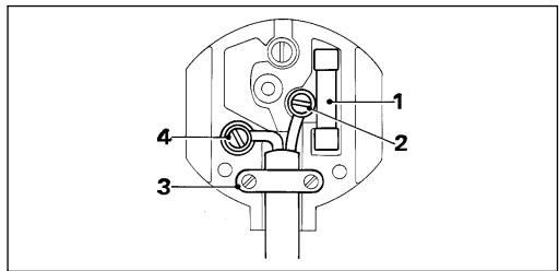
Only fit 13 Amperes BS1363A approved plugs fitted with the correctly rated fuse (1).
The cable wire colours, or a letter, will be marked at the connection points of most good quality plugs. Attach the wires to their respective points in the plug (see above). Brown is for Live (L) (2), blue is for Neutral (N) (4).
Before replacing the top cover of the mains plug ensure that the cable restraint (3) is holding the outer sheath of the cable firmly and that the leads are correctly fixed at the terminal screws.
If the plug has a fuse cover, make sure that the fuse cover is fitted.
8
SAG.P65
8
17-07-2001, 14:51


ENGLISH
Do not use the plug if the fuse cover is missing or damaged.

Never use a light socket.
Using an extension cable
Always use an approved extension cable suitable for the power input of this tool (see technical data). Before use, inspect the extension cable for signs of damage, wear and ageing. Replace the extension cable if damaged or defective. When using a cable reel, always unwind the cable completely. Use of an extension cable not suitable for the power input of the tool or which is damaged or defective may result in a risk of fire and electric shock.
CARTON CONTENTS
The carton contains:
1 Angle grinder
1 Side handle
1 Flange set
1 Two-pin spanner
1 Wrench (KG68/CD500)
1 Instruction manual
Carefully unpack all parts.
Please note that additional items may be found in the carton, depending on the letter suffix following the catalogue number of your tool.
OVERVIEW (fig. A)
- On/off switch
- Side handle
- Spindle lock (KG70/KG75)
- Guard
- Grinding or cutting disc
ASSEMBLY

Before attempting any of the following operations, make sure that the tool is switched off and unplugged.
Fitting and removing the guard
Fitting (fig. B)
Place the tool on a table, with the spindle (6) facing up.
Hold the guard (4) over the tool as shown.
Align the lug (7) with the slot (8).
Press the guard down (A) and turn it counterclockwise (B).
Removing (fig. C)
While holding the tool, turn the guard (4) clockwise.
Use a screwdriver to press down the locking pin (9).
Release the guard and take it off the tool.

Never use the tool without the guard, except when sanding.
Fitting the side handle (fig. A)
Screw the side handle (2) into one of the mounting holes in the tool.

Always use the side handle.
Fitting and removing grinding or cutting discs (fig. A, D - G)

Always use the correct type of disc for your application. Always use discs with the correct diameter and bore size (see technical data). The maximum thickness for grinding discs is 6mm for cutting discs 3.5mm .
Fitting
Fit the guard as described above.
Place the inner flange (10) onto the spindle (6) as shown (fig. D). Make sure that the flange is correctly located on the flat sides of the spindle.
Place the disc (5) onto the spindle (6) as shown (fig. E). If the disc has a raised centre (11), make sure that the raised centre faces the inner flange.
Make sure that the disc locates correctly on the inner flange (not for KG70).
ENGLISH
KG70: Place the outer flange (12) onto the spindle with the raised centre facing towards the disc (A in fig. F).
KG68/KG75/CD500: Place the outer flange (12) onto the spindle. When fitting a grinding disc, the raised centre on the outer flange must face towards the disc (A in fig. F). When fitting a cutting disc, the raised centre on the outer flange must face away from the disc (B in fig. F).
KG68/CD500: Hold the spindle using the wrench (13) and tighten the outer flange using the two-pin spanner (14) (fig. G).
KG70/KG75: Keep the spindle lock (3) depressed and tighten the outer flange using the two-pin spanner (14) (fig. A & G).
Removing
KG68/CD500: Hold the spindle using the wrench (13) and loosen the outer flange (12) using the two-pin spanner (14) (fig. G).
KG70/KG75: Keep the spindle lock (3) depressed and loosen the outer flange (12) using the two-pin spanner (14) (fig. A & G).
Remove the outer flange (12) and the disc (5).
Fitting and removing sanding discs (fig. A, H & I)
For sanding, a backing pad is required.
The backing pad is available from your Black & Decker dealer as an accessory.
Fitting
Remove the guard as described above.
Place the inner flange (10) onto the spindle (6) as shown (fig. H). Make sure that the flange is correctly located on the flat sides of the spindle
Place the backing pad (15) onto the spindle.
Place the sanding disc (16) onto the backing pad.
Place the outer flange (12) onto the spindle with the raised centre facing away from the disc.
KG68/CD500: Hold the spindle using the wrench (13) and tighten the outer flange using the two-pin spanner (14) (fig. 1).
KG70/KG75: Keep the spindle lock (3) depressed and tighten the outer flange using the two-pin spanner (14) (fig. A & I).
Removing
KG68/CD500: Hold the spindle using the wrench (13) and loosen the outer flange (12) using the two-pin spanner (14) (fig. l).
KG70/KG75: Keep the spindle lock (3) depressed and loosen the outer flange (12) using the two-pin spanner (14) (fig. A & I).
Remove the outer flange (12), the sanding disc (16) and the backing pad (15).

After sanding, refit the guard on the tool.
USE

Let the tool work at its own pace.
Do not overload.
Carefully guide the cable in order to avoid accidentally cutting it.
Be prepared for a stream of sparks when the grinding or cutting disc touches the workpiece.
Always position the tool in such a way that the guard provides optimum protection from the grinding or cutting disc.
Switching on and off (fig. J)
To switch on, slide the on/off switch (1) forward.
To switch off, press the rear part of the on/off switch.
Hints for optimum use
Firmly hold the tool with one hand around the side handle and the other hand around the motor housing (fig. K).
When grinding, always maintain an angle of approx. 15^ between the disc and the workpiece surface (fig. L).
MAINTENANCE
Your Black & Decker tool has been designed to operate over a long period of time with a minimum of maintenance. Continuous satisfactory operation depends upon proper tool care and regular cleaning.
10
ENGLISH

Before performing any maintenance, switch off and unplug the tool.
Regularly clean the ventilation slots in your tool using a soft brush or dry cloth.
Regularly clean the motor housing using a damp cloth. Do not use any abrasive or solvent-based cleaner.
PROTECTING THE ENVIRONMENT

Should you find one day that your tool needs replacement, or if it is of no further use to you, think of the protection of the environment. Black & Decker repair agents will accept old Black & Decker tools and ensure that they are disposed of in an environmentally safe way.
Technical data
| KG68 | KG70 | ||
| Voltage | VAC | 230 | 230 |
| Power input | W | 680 | 700 |
| No-load speed | min-1 | 10,000 | 10,000 |
| Disc diameter | mm | 115 | 100 |
| Disc bore | mm | 22 | 16 |
| Spindle size | M14 | M10 | |
| Weight | kg | 2.3 | 2.2 |
| KG75 | CD500 | ||
| Voltage | \(V_{AC}\) | 230 | 230 |
| Power input | W | 750 | 680 |
| No-load speed | \(\mathsf{min}^{-1}\) | 10,000 | 10,000 |
| Disc diameter | mm | 115 | 115 |
| Disc bore | mm | 22 | 1622 |
| Spindle size | M14 | M14 | |
| Weight | kg | 2.4 | 2.3 |
GUARANTEE (UK, SOUTH AFRICA,
AUSTRALIA AND NEW ZEALAND ONLY)
Should your Black & Decker product become defective due to faulty materials or workmanship, within 24 months from the date of purchase, we guarantee to either replace all defective parts or -at our discretion- to replace the unit free of charge, provided that:
The product is returned to us or one of our authorised repair agents with proof of purchase.
The product has not been used for trade, professional or hire purposes.
The product has not been subjected to misuse or neglect.
The product has not sustained any damage through foreign objects, substances or accidents.
Repairs have not been attempted by anyone other than our service staff or authorised repair agents.
This guarantee is offered as an extra benefit and does not affect your statutory rights.
AFTER SALES SERVICE
(UK, SOUTH AFRICA, AUSTRALIA AND NEW ZEALAND ONLY)
Black & Decker offers a nationwide network of authorised repair agents. The use of other than genuine Black & Decker parts and accessories may reduce the performance of the tool and cause personal injury and material damage. The terms and conditions of the warranty could also be rendered void.
OUR AFTER SALES SERVICE POLICY (UK, AUSTRALIA AND NEW ZEALAN ONLY)
Full details on our after-sales service are available on the Internet at www.2helpU.com.
Alternatively, contact our Service and Information Centre at the address towards the back of this manual.
It is our aim that all Black & Decker customers should be totally satisfied with their Black & Decker product and our after sales service. If any help or advice is needed, please contact your local Black & Decker repair agent.
If your product needs repair, please take or send it to an authorised repair agent, providing proof of purchase if claiming a guarantee repair.
ENGLISH
OTHER DIY TOOLS
Black & Decker has a full range of tools that make DIY jobs easy. If you would like further information on the following products, please contact our Service and Information Centre (see the address page towards the end of this manual) or your local Black & Decker retailer.
Drills
Cordless screwdrivers Cordless drills/screwdrivers
Sanders
Jigsaws
Circular saws
Mitre saws
Angle grinders
Planers
Routers
Cored and cordless multi-purpose tools Paint strippers
Workbenches
We also have a wide range of accessories for the above tools.
Not all products are available in all countries.
WINKELSCHLEIFER KG68/KG70/KG75/CD500
HERZLICHEN GLUCKWUNSCH!
Brian Cooke
Director of Engineering
Spennymoor, County Durham DL16 6JG, United Kingdom
Brian Cooke
Director of Engineering
Spennymoor, County Durham DL16 6JG, United Kingdom
GEBRUK VOLGENS BESTEMMING
ANDERE MACHINES VOOR
DOE-HET-ZELVERS
Brian Cooke
Engenheiro Responsavel
Spennymoor, County Durham DL16 6JG, United Kingdom
11.Tire as chaves de aperto
Brian Cooke
Director of Engineering
Spennymoor, County Durham DL16 6JG, United Kingdom
ANVÄNDNINGSOMRÄDE
Director of Engineering
Spennymoor, County Durham DL16 6JG
United Kingdom
BRUKSOMRÄDER
ANDRE GJØR-DET-SELV VERKTØY
Brian Cooke
Director of Engineering
Spennymoor, County Durham DL16 6JG, United Kingdom

ANVENDELSESOMRADE
OPSLIDT VÆRKTØJ OG MILJØET

ANDET GØR-DET-SELV VÆRKTØJ
Director of Engineering
Spennymoor, County Durham DL16 6JG, United Kingdom
KÄYTTÖTARKOITUS
Is this tool your first purchase? Ist.
m = 311
Is this tool your first purchase? Ist
deses Gerat eir Esrkaut? Est-eun 1er cebst? Oquete prelatte ? iluwn
Téché àchat? •Quito produit en su nombre最初 accuta? •Is deze machine uW
eerste aankoop? Es this