
EVOLUTION WIRELESS EW 100 - Wireless Microphone System SENNHEISER - Free user manual and instructions
Find the device manual for free EVOLUTION WIRELESS EW 100 SENNHEISER in PDF.
| Product type | Wireless microphone system |
| Brand | SENNHEISER |
| Model | EVOLUTION WIRELESS EW 100 |
| Fixed receiver EM 100 - Dimensions | 212 x 145 x 38 mm |
| Fixed receiver EM 100 - Weight | Approx. 1100 g |
| Fixed receiver EM 100 - Power supply | 10.5 - 16 V DC (nominal 12 V DC) |
| Pocket receiver EK 100 - Dimensions | 110 x 65 x 22 mm |
| Pocket receiver EK 100 - Weight | Approx. 255 g |
| Pocket receiver EK 100 - Power supply | 9 V battery (IEC 6 LR 61) |
| Pocket transmitter SK 100 - Dimensions | 110 x 65 x 22 mm |
| Pocket transmitter SK 100 - Weight | Approx. 255 g |
| Pocket transmitter SK 100 - Battery life | > 8 hours (alkaline battery) |
| Microphone transmitter SKM 100 - Dimensions | Ø 50 x 225 mm |
| Microphone transmitter SKM 100 - Weight | Approx. 450 g |
| Available frequency ranges | A: 518-550 MHz, B: 630-662 MHz, C: 740-772 MHz, D: 790-822 MHz |
| Reception technology | True Diversity (EM 100 receiver) |
| Noise reduction | HDX (wideband compander) |
| Main functions | Sensitivity adjustment, adjustable squelch, key lock, 4 channel presets, tuning in 25 kHz steps |
| Maintenance | Clean with a soft cloth. For the SKM 100 grille, unscrew and clean with a damp cloth without detergent |
| Safety | Do not open the device. Service only by qualified personnel. Disconnect power before modification. Avoid moisture and heat sources |
| Compatible accessories | Microphone capsules MD 835, MD 845, ME 865; lavalier microphones ME 2, ME 4; headset ME 3; antenna cables, coupler ASP 1, etc. |
Frequently Asked Questions - EVOLUTION WIRELESS EW 100 SENNHEISER
User questions about EVOLUTION WIRELESS EW 100 SENNHEISER
0 question about this device. Answer the ones you know or ask your own.
Ask a new question about this device
Download the instructions for your Wireless Microphone System in PDF format for free! Find your manual EVOLUTION WIRELESS EW 100 - SENNHEISER and take your electronic device back in hand. On this page are published all the documents necessary for the use of your device. EVOLUTION WIRELESS EW 100 by SENNHEISER.
USER MANUAL EVOLUTION WIRELESS EW 100 SENNHEISER
Moderation: -20 / -10 dB
Interview: -10/0 dB
588.588
-80.88
(Pleases read BEFORE using)
Licence-Free Operation in the UK
For licence-free operation in the UK the frequency window MUST be restricted to 863-865MHz before the equipment can legally be used. Please proceed as follows:-
1) While holding down the SET and UP buttons, switch on the transmitter until "LoLi" is displayed.
2) Then use the UP and DOWN buttons to adjust the lower frequency limit to 863.000MHz .
3) Press SET to store.
4) The program will automatically change to "Altering the upper range limit" and "HiLi" will be displayed.
5) Use the UP and DOWN buttons to adjust the upper frequency limit to 865.000MHz.
6) Press SET to store.
7) The transmitter is now set for operation on the de-regulated licence-free frequencies only and can legally be used in the UK without requiring a licence. (nb: This restriction, once set, cannot be reversed by the user - this is a legal requirement).
Failure to comply with the above will mean that the transmitter cannot legally be operated at 863-865MHz and the user would be liable to prosecution.
For UK licensed operation:
Please contact JFMG for frequency allocation and obtaining a licence.
Tel: 020-7261-3797 • Fax: 020-7737-8499 • e-mail: admin@jfmg.co.uk
Ch.69 Shared Frequencies:
There are 14 frequencies in TV channel 69 that can be used on a shared basis throughout the UK. Eight of these will work intermodulation-free with evolutionwireless transmitters. Four of these ch.69 frequencies are set as standard (presets 6-8), however if more than four frequencies are required please re-set the first four frequency memories (see instruction manual) to the following frequency set:-
Presets 1-4 (change to)
1 856.575
2 857.625
3 860.400
4 861.550
Presets 5-8 (already set)
5 855.275
6 856.175
7 858.200
8 860.900
Co-ordinated Frequencies in other bands:
There are many other frequency bands available in the UK on a co-ordinated "fixed site" basis. Please contact JFMG for details of the channels available in your area. Sennheiser UK can supply you with intermodulation-free frequency sets for your allocated channel.
INSTRUCTION MANUAL
evolution wireless Series
Cw 100


1 Contents
Chap. Contents
Page
1 Contents 46
2 Short description 47
3 Important notes 47
4 System variants 48
5 Preparing the devices for use 51
EM 100 receiver 51
EK 100 pocket receiver 54
SK 100 pocket transmitter 57
SKP 100 plug-on transmitter 60
SKM 100 hand-held transmitter 63
6 Operation 66
7 Troubleshooting 75
8 Care and maintenance 77
9 Overview 78
Wireless transmission systems 78
HDX noise reduction 79
Connector assignment 79
Diversity reception 80
Technical data 81
Accessories 84
Licences 255
Thank you for choosing Sennheiser!
We have designed these products to give you reliable operation over many years.
Please take a few moments to read these instructions carefully, as we want you to enjoy your new Sennheiser products quickly and to the full.
2 Short description
With the evolution wireless series ew 100, Sennheiser offers musicians, video and sound amateurs high-quality state-of-the-art RF transmission systems with a high level of operational reliability and ease of use. Transmitters and receivers permit wireless transmission with studio-quality sound. Due to further optimised PLL and microprocessor technology, the HDX noise reduction system and true diversity technology (not pocket receivers), these transmission systems ensure interference-free transmission and minimise dropouts in the RF link.
The systems can be supplied in five frequency ranges within the UHF band. Please note: Frequency usage is different for each country. Your Sennheiser agent will have all the necessary details on the available legal frequencies for your area.
Range A: 518 - 550 MHz,
Range B: 630 - 662 MHz,
Range C: 740 - 772 MHz,
Range D: 790 - 822 MHz,
ew 100 transmitters and receivers are 4-channel switchable. Each transmitter and receiver has 4 frequency memories to store up to 4 transmission/receiving frequencies. The frequencies are selectable in 25-kHz steps, giving a selection of 1280 frequencies within the preset 32MHz frequency range.
Each system has 4 factory-preprogrammed frequencies, so that
- the systems are ready for immediate use after switch-on,
- several systems can be operated simultaneously on the factory-preset transmission and receiving frequencies without causing intermodulation interference. However, all frequency settings can be changed to your individual needs, if required.
Each system consists of
- a receiver (mains or pocket),
- a hand-held/pocket/plug-on transmitter and
- comes complete with all necessary accessories.
3 Important notes
Never open electronic devices! This must only be done by authorised personnel and is all the more important for units connected to AC outlets. If devices are opened by customers in breach of this instruction, the warranty is voided.
Always disconnect the devices from the mains by removing the plug when you wish to change connections or move the devices to a different place.
Keep the devices away from central heating radiators and electric heaters.
Never expose them to direct sunlight.
Use the devices in dry rooms only.
Use a damp cloth for cleaning the devices. Do not use any cleansing agents or solvents.
Varnish or furniture polish may degrade the rubber feet of the transmitter. Place the transmitter on a nonslip pad to avoid potential staining of furniture.

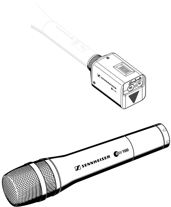
EM 100

EK 100

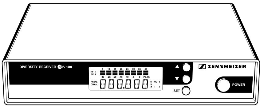
SK 100
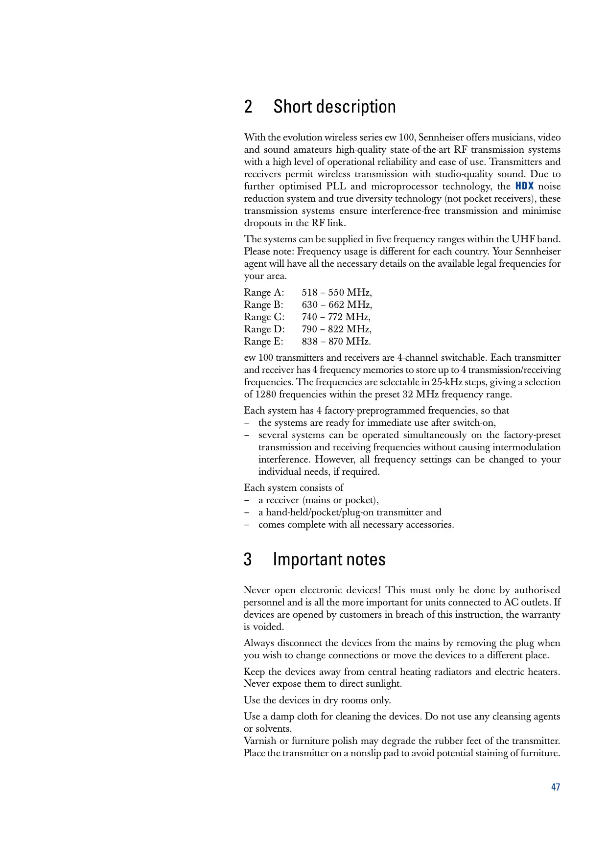
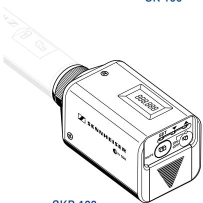
SKP 100
4 System variants
Setew 101
This is a versatile system suitable for many applications. The plug-on transmitter converts a standard wired microphone into a radiomicophone. Set ew 101 consists of: EM 100 receiver, SKP 100 plug-on transmitter, plug-in mains unit, battery, antennas and operating manual.
Set CW 101-p
Having the same transmitter as the Set ew 101, this system replaces the mains receiver with a pocket receiver for camera-mounted applications. Set ew 101-p consists of: EK 100 pocket receiver, SKP 100 plug-on transmitter, two batteries, antennas, line output cable, camera kit and operating manual.
Setew112
This system is ideal for theatre and presentation use. The unobtrusive clip-on microphone is virtually invisible, and its omni-directional pattern minimises drop-outs caused by the speaker turning his/her head.
Set ew 112 consists of: EM 100 receiver, SK 100 pocket transmitter, ME 2 miniature clip-on omni-directional condenser microphone, plug-in mains unit, battery, antennas and operating manual.
Set C w 112-p
Having the same transmitter as the Set ew 112, this system replaces the mains receiver with a pocket receiver for camera-mounted applications. Set ew 112-p consists of: EK 100 pocket receiver, SK 100 pocket transmitter, ME 2 miniature clip-on omni-directional condenser microphone, two batteries, antennas, line output cable, camera kit and operating manual.
Setew 122
This system is ideal for presentation and PA applications in acoustically difficult rooms. The unobtrusive cardioid clip-on microphone can be directed towards the speaker's mouth.
Set ew 122 consists of: EM 100 receiver, SK 100 pocket transmitter, ME 4 miniature clip-on cardioid condenser microphone, plug-in mains unit, battery, antennas and operating manual.
Set CW 122-p
Having the same transmitter as the Set ew 122, this system replaces the mains receiver with a pocket receiver for camera-mounted applications.
Set ew 122-p consists of: EK 100 pocket receiver, SK 100 pocket transmitter, ME 4 miniatureclip-on cardioid condenser microphone, two batteries, antennas, line output cable, camera kit and operating manual.

SKM 100
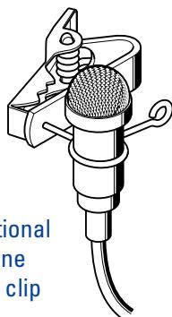
ME 2 omni-directional clip-on microphone with microphone clip
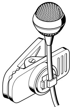
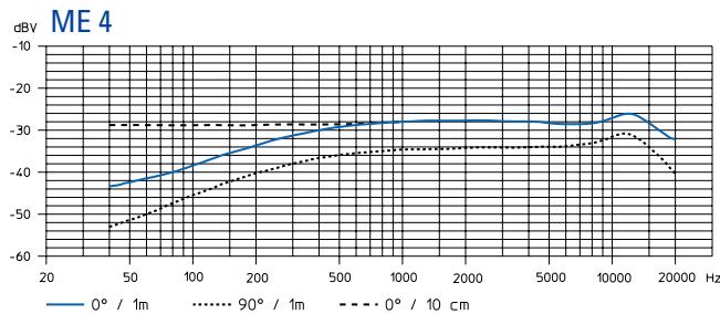
ME 4 cardioid clip-on microphone with microphone clip
Setew 135
This system is ideal for vocal applications.
Set ew 135 consists of: EM 100 receiver, SKM 100 hand-held transmitter with MD 835 cardioid dynamic microphone module, plug-in mains unit, battery, antennas, microphone clamp and operating manual.
Setew 135-p
Having the same transmitter as the Set ew 135, this system replaces the mains receiver with a pocket receiver for camera-mounted applications.
Set ew 135-p consists of: EK 100 pocket receiver, SKM 100 hand-held transmitter with MD 835 cardioid dynamic microphone module, two batteries, antennas, line output cable, camera kit, microphone clamp and operating manual.
Setew 145
This system is ideal for vocal applications in venues with high ambient noise levels. The super-cardioid dynamic microphone head has excellent feedback rejection.
Set ew 145 consists of: EM 100 receiver, SKM 100 hand-held transmitter with MD 845 super-cardioid dynamic microphone module, plug-in mains unit, battery, antennas, microphone clamp and operating manual.
Setew 145-p
Having the same transmitter as the Set ew 145, this system replaces the mains receiver with a pocket receiver for camera-mounted applications.
Set ew 145-p consists of: EK 100 pocket receiver, SKM 100 hand-held transmitter with MD 845 super-cardioid dynamic microphone module, two batteries, antennas, line output cable, camera kit, microphone clamp and operating manual.
Setew 152
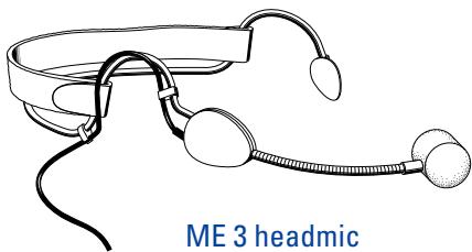
This system is ideal for hands-free vocal applications. Supplied complete with the ME 3 headmic (which has superb feedback rejection), this system gives complete freedom of expression to stage vocalists as well as proving a boon to sports commentators/referees and aerobic instructors.
Set ew 152 consists of: EM 100 receiver, SK 100 pocket transmitter, ME 3 condenser super-cardioid headmic, plug-in mains unit, battery, antennas and operating manual.
Setew 152-p
Having the same transmitter as the Set ew 152, this system replaces the mains receiver with a pocket receiver for camera-mounted applications.
Set ew 152-p consists of: EK 100 pocket receiver, SK 100 pocket transmitter, ME 3 condenser super-cardioid headmic, two batteries, antennas, line output cable, camera kit and operating manual.
Setew 165
This system, due to its excellent feedback rejection and wide dynamic range, is the ideal choice for vocals and presentations.
Set ew 165 consists of: EM 100 receiver, SKM 100 hand-held transmitter with ME 865 super-cardioid condenser microphone module, plug-in mains unit, battery, antennas, microphone clamp and operating manual.
Setew 165-p
Having the same transmitter as the Set ew 165, this system replaces the mains receiver with a pocket receiver for camera-mounted applications.
Set ew 165-p consists of: EK 100 pocket receiver, SKM 100 hand-held transmitter with ME 865 super-cardioid condenser microphone module, two batteries, antennas, line output cable, camera kit, microphone clamp and operating manual.
Setew 172
This system is for connecting musical instruments (e.g. guitar) which have a 1/4 ” (6.3 mm) jack socket directly to the pocket transmitter.
Set ew 172 consists of: EM 100 receiver, SK 100 pocket transmitter, CI 1 instrument (guitar) cable, plug-in mains unit, battery, antennas and operating manual.
Setew 172-p
Having the same transmitter as the Set ew 172, this system replaces the mains receiver with a pocket receiver for camera-mounted applications.
Set ew 172-p consists of: EK 100 pocket receiver, SK 100 pocket transmitter, CI 1 instrument (guitar) cable, two batteries, antennas, line output cable, camera kit and operating manual.
5 Preparing the devices for use
EM 100 receiver
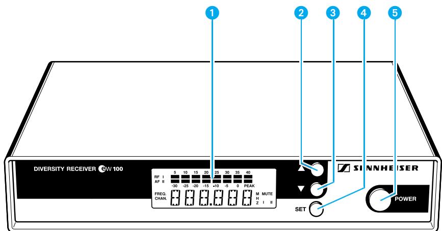
LC display
2 button (UP)
3 button (DOWN)
4 SET button
5 POWER (ON/OFF) button
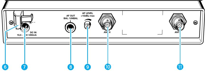
6 Cable grip for power supply DC cable
DC socket for connection of mains unit (DC-IN)
AF output, 1/4 (6.3 mm) jack socket (AF OUT BAL/UNBAL)
AF output level control (AF LEVEL)
Antenna input II (ANT II), BNC socket
Antenna input I (ANT I), BNC socket
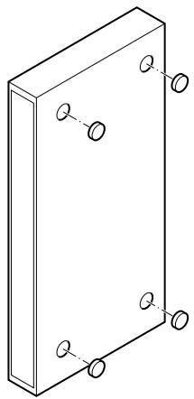
Mounting the rubber feet
To ensure that the receiver cannot slip on the surface on which it is placed, four self-adhesive soft rubber feet are supplied. These feet are stuck into the recesses on the bottom side of the receiver. (N.B.: Do not use these feet if rackmounting the receiver).
Ensure that the recesses are clean and free from grease before fixing the feet.
Attention!
Some furniture surfaces have been treated with varnish, polish or synthetics which might cause stains when they come into contact with other synthetics. Despite a thorough testing of the synthetics used by us, we cannot rule out the possibility of discolouration, since we don't know your furniture. You should therefore always place the receiver on a non-slip pad.
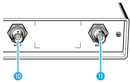
Connecting the antennas
The EM 100 receiver can be used with either telescopic antennas (supplied) or remote antennas (available as accessories).
The supplied telescopic antennas can be mounted quickly and easily to the rear of the receiver and are suitable for all applications where - good reception conditions provided - a wireless transmission system is to be used without a large amount of installation work.
Connect the telescopic antennas to BNC sockets ⑩ and ⑪ at the rear of the receiver. Pull the antennas out and align them upwards in a V-shape.
If the receiver position is not the best antenna position for optimum reception, you can use remote antennas. These are available as accessories.
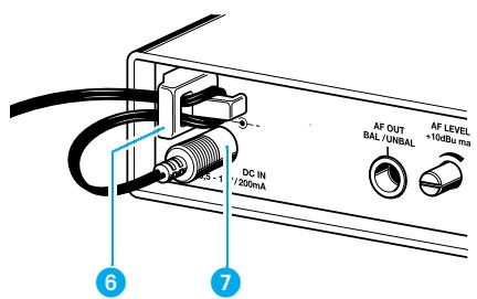
Connecting the mains unit
Insert the DC connector on the power supply output cable into socket at the rear of the receiver.
Pass the cable through the cable grip 6.
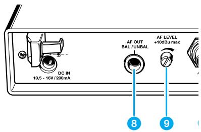
Connecting the amplifier/mixing console
Connect the amplifier/mixing console to the 1 / 4 (6.3 mm) jack socket 8.
For information on balanced and unbalanced connection, please refer to the chapter "9 Overview".
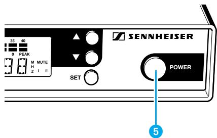
Switching the receiver on/off
Press the POWER button 5 to switch the receiver on.
To switch the receiver off, press the POWER button until "OFF" appears on the display. You can then release the button.
After a power failure, the device returns to the previous setting (ON/OFF).
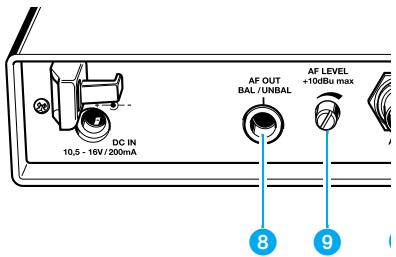
Adjusting the AF output level
Use the AF output level control 9 to adjust the AF signal level that appears at output 8.
EK 100 pocket receiver
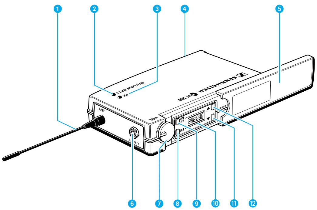
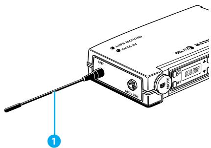
Antenna
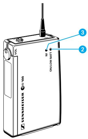
2 Red LED for operation and battery status indication (ON/LOW BAT)
3 Green LED for RF signal indication (RF)
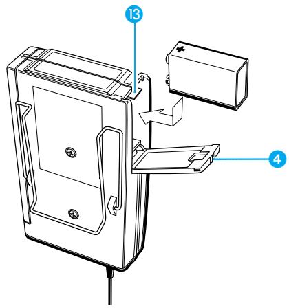
4 Cover plate for battery compartment
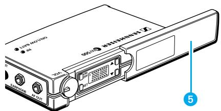
5 Cover plate for display and operating controls
6 AF output (AF OUT), 3.5mm jack socket
AF output level control
8 SET button
ON/OFF button
LC display
13 button (DOWN)
12 button (UP)
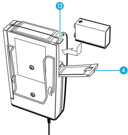
Inserting and changing the battery
▶ Slide the cover of the battery compartment ④ in the direction of the embossed arrow until it clicks audibly.
Open the cover.
Insert the 9 V PP3 battery (IEC 6 LR 61). Please observe correct polarity when inserting the battery.
Close the battery compartment.
To remove the battery, push the small red lever 13 in the battery compartment towards the bottom side of the receiver.
Note:
We recommend powering the receiver by a standard PP3 alkaline battery. If powered by a rechargeable 9V battery, the operating time will be drastically reduced.
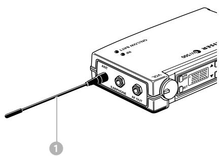
Connecting the antenna
Screw the antenna 1 onto the antenna socket (M3 connection).
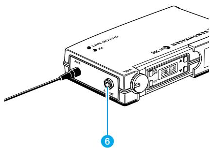
Connecting sound recording and reproducing equipment
Sound recording and reproducing equipment such as amplifiers, video cameras, tape recorders etc. can be connected to the EK 100 receiver.
Use the supplied line cable with 3.5mm jack plug to connect the sound recording or reproducing device to the line output (AF OUT) 6.
Lock the jack plug by screwing down the locking ring.
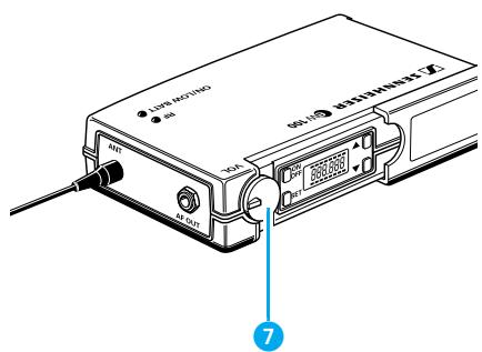
Adjusting the AF output level
Use the AF output level control to adjust the AF signal level for socket 6.
Switching the receiver on/off
▶ Slide back the cover plate ⑤.
Press the ON/OFF button to switch the receiver on. The red LED lights up.
To switch the receiver off, press the ON/OFF button until "OFF" appears on the display. You can then release the button. The red LED goes off.
Signal and battery status indication
The green LED ③ at the top of the EK 100 receiver indicates that an RF signal is being received.
Battery status indication
The red LED 2 provides information on the (remaining) battery capacity: LED lit up:
The receiver is switched on and the battery capacity is sufficient.
LED flashing:
The battery is going flat! You should immediately replace the battery.
Attachment of the receiver to clothing
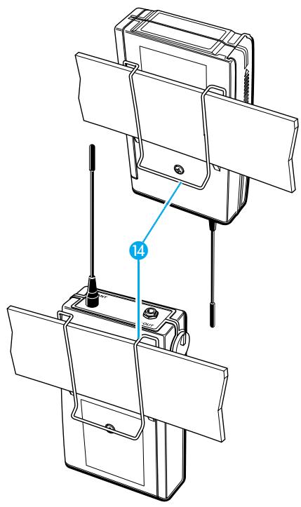
The EK 100 receiver is best attached to e.g. the belt with clip 14.
The clip is detachable so that you can also attach the receiver with the antenna pointing downwards. To do so, withdraw the clip from its fixing points and attach it the other way round.
Attachment of the receiver to a camera
Use the supplied camera kit (self-adhesive Velcro tape) to attach the receiver to a camera. Remove the clip 14 and stick the Velcro tape to the receiver and the camera. Ensure that the surfaces are clean and free from grease.
(Note: We would suggest using the "hook" Velcro on the receiver and the "loop" Velcro on the camera.)
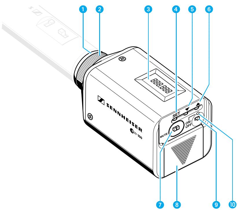
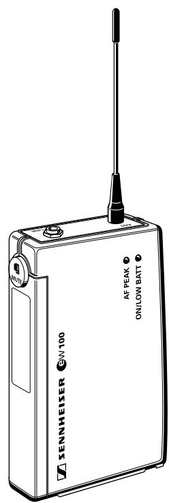
SK 100 pocket transmitter
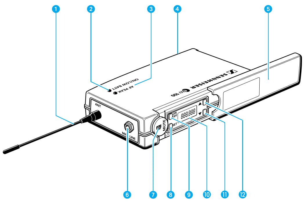
Antenna
2 Red LED for operation and battery status indication (ON/LOW BAT)
3 Yellow LED for AF peak (AF PEAK)
4 Cover plate for battery compartment
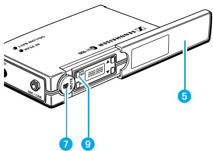
5 Cover plate for display and operating controls
6 AF input (MIC/LINE), 3.5mm jack socket
MUTE switch
8 SET button
9 ON/OFF button
10 Display
13 button (DOWN)
12 button (UP)
Inserting and changing the battery
▶ Slide the cover of the battery compartment 4 in the direction of the embossed arrow until it clicks audibly.
Open the cover.
Insert the 9 V PP3 battery (IEC 6 LR 61). Please observe correct polarity when inserting the battery.
Close the battery compartment.
To remove the battery, push the small red lever 13 in the battery compartment towards the bottom side of the transmitter.
Note:
We recommend powering the transmitter by a standard PP3 alkaline battery. If powered by a rechargeable 9V battery, the operating time will be drastically reduced.
Connecting the antenna
Screw the antenna 1 onto the antenna socket (M3 connection).
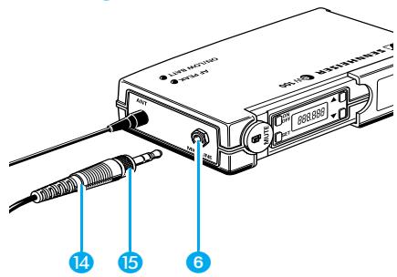
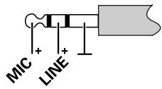
Connecting the microphone/line cable
Electret powering ("plug-in" power) is available at the AF input for powering the microphone.
Connect the 3.5mm jack plug 14 from the microphone/line cable to the AF input (MIC/LINE) 6.
Lock the jack plug by screwing down the locking ring 15.
Switching the transmitter on/off
▶ Slide back the cover plate ⑤.
Press the ON/OFF button to switch the transmitter on. The red LED lights up.
To switch the transmitter off, press the ON/OFF button until “OFF” appears on the display. You can then release the button. The red LED goes off.
Muting the transmitter
Use the MUTE switch ⑦ to noiselessly mute the transmitter's audio signal (this switch does not switch off the transmitter).
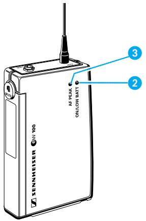

Signal and battery status indication
The yellow LED 3 at the top of the SK 100 transmitter lights up if the audio signal at the AF input is excessively high (AF peak).
The red LED 2 provides information on the battery status:
LED lit up:
The transmitter is switched on and the battery capacity is sufficient.
LED flashing:
The battery is going flat! You should immediately replace the battery.
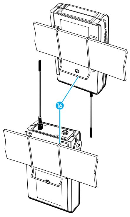
Attachment of the transmitter to clothing
The SK 100 transmitter is best attached to e.g. the belt with clip 16.
The clip is detachable so that you can also attach the transmitter with the antenna pointing downwards. To do so, withdraw the clip from its fixing points and attach it the other way round.
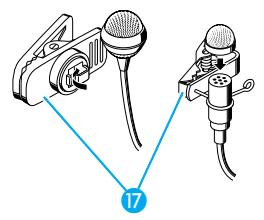
Attachment of the microphones
The microphone clips enable the attachment of the ME 2 and ME 4 clip on microphones to clothing (e.g. tie, lapel).
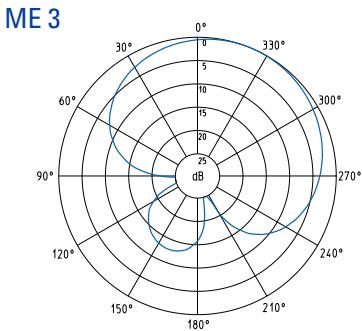
The ME 3 headmic is adjustable to comfortably and securely fit your head.
Positioning the microphones
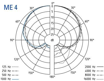
The ME 3 and ME 4 microphones are directional microphones, i.e. their sound inlet should always be directed towards the sound source (e.g. mouth). The ME 2 with omni-directional pick-up pattern picks up sound equally from all directions. It is the best choice if movements of the speaker's head have to be compensated for.
Microphone input, XLR-3 socket
2 Mechanical locking ring of XLR-3 socket
3 LC display
SET button
5 button (DOWN)
6 button (UP
MUTE switch
Battery compartment
9 ON/OFF button
Red LED for operation and battery status indication
Inserting and changing the battery
▶ Slide the cover of the battery compartment ⑧ in the direction of the arrow until it clicks audibly and open the cover.
Insert the 9 V PP3 battery (IEC 6 LR 61). Please observe correct polarity when inserting the battery.
Close the battery compartment.
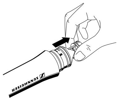
Plugging the transmitter onto the microphone
Plug the transmitter's XLR-3 connector ① onto the microphone's XLR-3 socket.
Tighten the locking ring ②.
Note:
The transmitter uses the microphone body as an antenna – therefore only microphones with a metal casing should be used for best signal transmission.
Switching the transmitter on/off
Press the ON/OFF button to switch the transmitter on. The red LED lights up.
To switch the transmitter off, press the ON/OFF button until “OFF” appears on the display. You can then release the button. The red LED goes off.
Muting the transmitter
Use the MUTE switch ⑦ to noiselessly mute the transmitter's audio signal (this switch does not switch off the transmitter).
Battery status indication
The red LED 10 provides information on the (remaining) battery capacity:
LED lit up:
The transmitter is switched on and the battery capacity is sufficient.
LED flashing:
The battery is going flat! You should immediately replace the battery
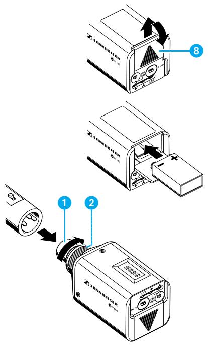
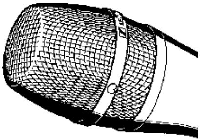
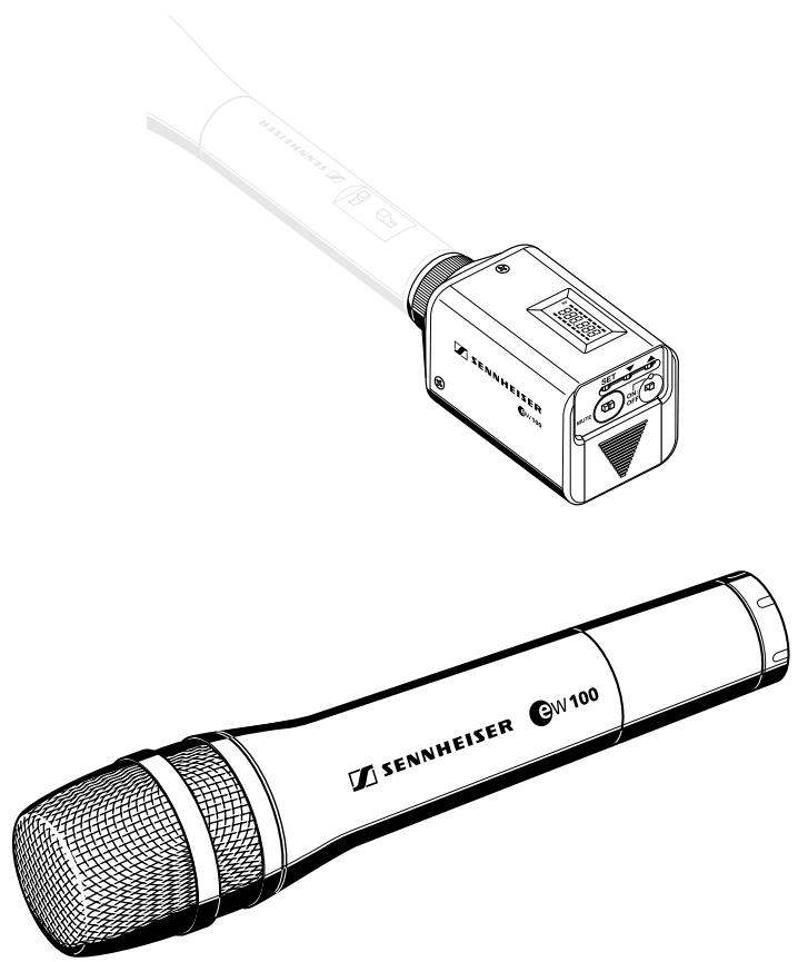
SKM 100 hand-held transmitter
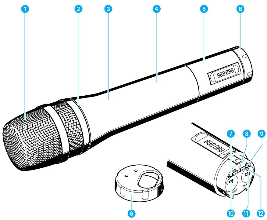
Sound inlet basket
Colour-coded identification ring for microphone modules green: MD 835 microphone module (cardioid dynamic microphone)
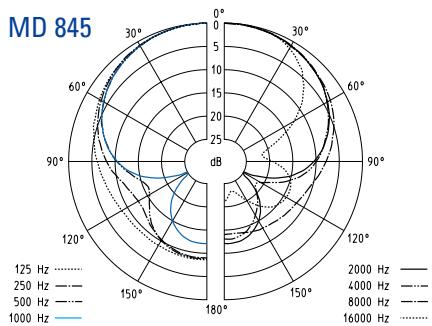
blue: MD 845 microphone module (super-cardioid dynamic microphone)
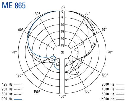
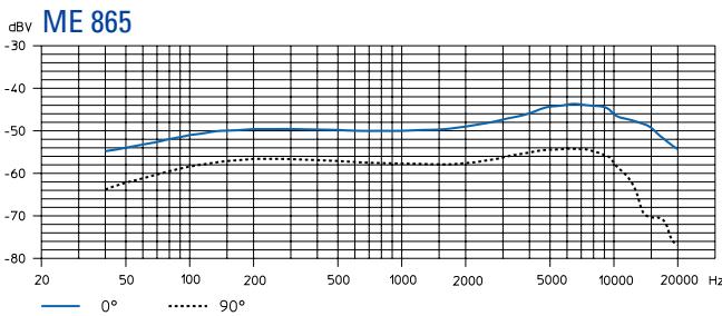
red: ME 865 microphone module (super-cardioid condenser microphone)
3 Body of hand-held transmitter
Battery compartment
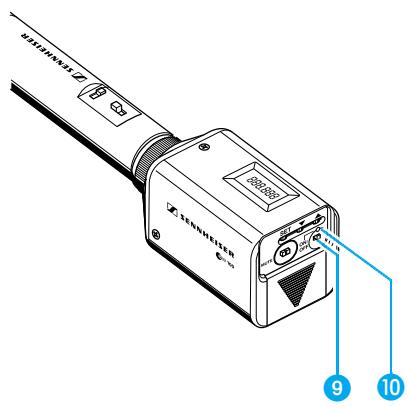
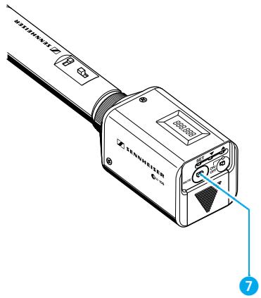
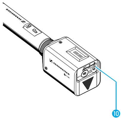
5 Display section
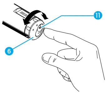
Turnable protective cap for operating controls (shown removed) The following operating controls become accessible in turn by turning the protective cap 6:
SET button
8 button (DOWN)
9 button (UP)
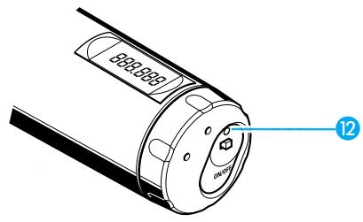
10 MUTE switch
1 ON/OFF button
Red LED for operation and battery status indication
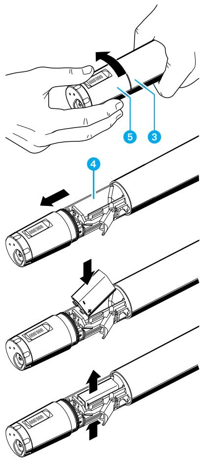
Inserting and changing the battery
Unscrew the display section 5 by turning it counter-clockwise.
▶ Slide back the display section ⑤ until the battery compartment ④ becomes fully accessible.
Insert the 9 V PP3 battery (IEC 6 LR 61). Please observe correct polarity when inserting the battery.
Push the the battery compartment into the radiomicrophone's body.
Screw the display section tight.
To change the battery, press out the battery from below (press in the direction of the arrow).
Switching the transmitter on/off
Turn the protective cap 6 at the bottom of the radiomicrophone so that the ON/OFF button becomes accessible.
Press the ON/OFF button to switch the transmitter on. The red LED lights up.
To switch the transmitter off, press the ON/OFF button until “OFF” appears on the display. You can then release the button. The red LED goes off.
Muting the transmitter
Use the MUTE switch to noiselessly mute the transmitter's audio signal (this switch does not switch off the transmitter).
Battery status indication
The red LED ② provides information on the (remaining) battery capacity:
LED lit up:
The transmitter is switched on and the battery capacity is sufficient.
LED flashing:
The battery is going flat! You should immediately replace the battery!
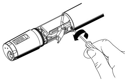
Changing the microphone module
First remove the battery and leave the radiomicrophone open.
Unscrew the sound inlet basket.
Loosen the screw and put it aside.
Remove the microphone module, as shown. Do not touch the contacts!
Insert the new module, secure the capsule by tightening the screw, put on the suitable sound inlet basket and coloured identification ring and screw it tight.
Insert the battery, close the radiomicrophone and put it into operation.
Note:
Microphone module, sound inlet basket and foam insert form an acoustic unit and must therefore always be exchanged all together. Each microphone module comes with a colour-coded identification ring to distinguish different microphone modules from each other (green = MD 835, blue = MD 845, red = ME 865).
6 Operation
Transmitters and receivers of the Sennheiser evolution wireless series ew 100 have been factory-preset to allow immediate use after switch-on (5 Preparing the devices for use). Please note, however, that the transmitter sensitivity is dependent on the application. To avoid overmodulation and distortion, please first check whether the preset sensitivity is suitable for your particular application (Adjusting the sensitivity).
Operating controls
ON/OFF Press the ON/OFF button or the POWER button (EM 100 receiver only) to POWER switch the transmitters and receivers on or off.
MUTE Use the MUTE switch (transmitters only) to noiselessly mute the audio signal without switching off the transmitter.
SET Press the SET button
- to select a menu,
- to change to the next menu,
- to return to the top menu level.
Press the UP button
- to adjust the setting of a menu.
Press the DOWN button
- to adjust the setting of a menu.
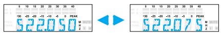
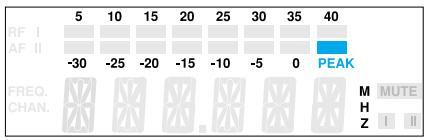
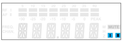
LC display panel
EM 100 receiver
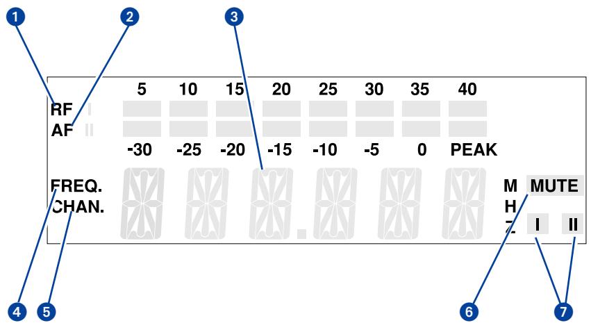
1 8-step level display for incoming RF signal
8-step level display for incoming AF signal, with "PEAK" warning
6-segment alphanumeric main display
Display for the "Frequency" menu. (This display can be the receiver's standard display which always appears after switch-on.)
Display for the channel number "Channel". (This display can be the receiver's standard display which always appears after switch-on.)
6 Squelch active ("MUTE")
Diversity display (antenna I or antenna II active) ("11 Diversity reception")
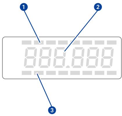
EK 100 receiver and SK 100, SKP 100, SKM 100 transmitters
8-step level display for incoming AF signal (EK 100 only)
2 Alphanumeric main display
8-step level display for incoming RF signal (EK 100 only)
Note:
If the operating steps for adjusting the settings via the menu are similar for all devices, only the main display of the EM 100 receiver is depicted.
Basic functions of the Sennheiser operating menu
A special feature of the Sennheiser evolution wireless series ew 100 is the similar operation of transmitters and receivers. In stressful situations, for example on stage or during a live show or presentation, it is important that the devices are easy to operate and that adjustments to the settings can be made quickly and "without looking". Therefore, the necessary operating steps for each device are similar.
Important:
With the / buttons you can directly switch between the factory-preset frequencies (channels presets). The display starts flashing. Your selection becomes effective immediately.
Press the SET button to enter the top menu level:
By briefly pressing SET again, you can change to the next menu. After approx. one second, the selected menu appears on the display and then the current setting of the menu is indicated.
Press the / buttons to adjust the settings of the selected menu:
The new setting starts flashing on the display. If you return to the previous setting, the flashing stops.
Important:
New settings become effective immediately and will be retained in memory on switch-off!
N.B.: When changing transmitter frequencies, care should be taken to avoid causing interference to other channels/users.
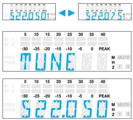
In the "TUNE" menu, the / buttons feature a "fast search" function. By briefly pressing the / buttons, the display jumps either forwards or backwards to the next setting. If you hold down a button, the cycling of the display is continuously accelerated. If you release the button and start over again, the cycling of the display restarts at normal speed. The "fast search" function allows you to get fast and easily to your desired setting.
Press the SET button to return to the top menu level:
Have you finished your entries? Press the SET button to return to the top menu level. The display then switches back to the standard setting.
Overview of menus
To ensure that transmitters and receivers of the Sennheiser evolution wireless Series ew 100 are easy to operate, the operating menus have been largely standardised:
| Display | Transmitters | Receivers |
| SEnSit | Adjusting the sensitivity (→ page 70) | - |
| SQELCH | - | Adjusting the squelch threshold (→ page 71) |
| att | Selecting the sensitivity range (SKP 100 only) (→ page 71) | - |
| DISPL | Selecting the content of the standard display (→ page 72) | Selecting the content of the standard display (→ page 72) |
| DiSPL | ||
| TUNE | Setting the transmission frequency (→ page 73) | Setting the receiving frequency (→ page 73) |
| tune | ||
| LOCK | Activating the lock-mode function to prevent accidental adjustment (→ page 74) | Activating the lock-mode function to prevent accidental adjustment (→ page 74) |
| Loc |
Selecting the frequency, channel number
- With the buttons you can directly switch between the factory-preset frequencies (channel presets). The display starts flashing. Your selection becomes effective immediately.
Press the SET button to acknowledge your selection. The display stops flashing. (If the SET button is not pressed, the receiver will store the new frequency automatically on switch-off.)
Note:
You can choose the content of the standard display i.e. whether the frequency or the channel number is displayed ( "Selecting the content of the standard display"). The receiver is factory-preset to show the frequency setting as standard.
SenSit
Adjusting the sensitivity (transmitters only)
Close talking distances, speakers with loud voices or loud music sequences may cause overmodulation in the transmission link, resulting in distortion. In this case, the "PEAK" warning of the EM 100's AF level display (as well as the SK 100 transmitter's yellow audio peak indication LED) will light up. If, on the other hand, the sensitivity is adjusted too low, the transmission link will be undermodulated, which would result in a signal with high background noise.
The sensitivity has to be adjusted such that the "PEAK" warning of the receiver's AF level display only lights up during the loudest passages.
The following figures are a guide to the best settings:
Loud music/vocals: -30 / -20 dB
Presentations: -20 / -10 dB
Interviews: -10/0 dB
588.588
-80.88
Select the "SEnSIt" menu by pressing the SET button until "SEnSIt" appears on the display; after a short pause the current sensitivity setting is displayed.
With the / buttons you can now select a different setting. The sensitivity can be adjusted in 10-dB steps from 0 to -30 dB. The new setting starts flashing on the display and becomes effective immediately.
Press the SET button to return to the top menu level. The display then switches back to the standard display.
SQELCH SqELCH
Adjusting the squelch threshold (receivers only)
The Sennheiser evolution wireless series ew 100 receivers are equipped with an adjustable squelch which eliminates annoying noise when the transmitters are switched off. It also suppresses sudden noise when a transmitter leaves the reception area and there is no longer sufficient transmitter power received by the receiver.
Select the "SQELCH" menu by pressing the SET button until "SQELCH" appears on the display; after a short pause the current squelch setting is displayed.
With the / buttons you can now select a different setting. The squelch can be switched off (0 dB) or adjusted in 5-dB steps from 5 dB to 40 dB. Selecting a smaller value reduces the squelch threshold, selecting a higher value increases the squelch threshold. The new setting starts flashing on the display. Set the squelch threshold - with the transmitter switched off - to the lowest possible value that suppresses hissing noise. If the squelch threshold is set too high, the transmission range will be reduced.
Note:
With the transmitter switched off and the squelch threshold set to "0 dB", hissing noise will occur. With the EM 100 receiver, the "PEAK" warning of AF level bargraph will light up.
Press the SET button to return to the top menu level. The display then switches back to the standard display.
Att
Selecting the sensitivity range (SKP 100 only)
Condenser microphones require a different sensitivity range than dynamic microphones. With the SKP 100 plug-on transmitter, you can switch the sensitivity range by 20~dB .


- Select the "Att" menu by pressing the SET button until "Att" appears on the display; after a short pause the current setting - i.e. "Att off" or "Att on" - is displayed.
With the / buttons you can now switch between two different sensitivity ranges.
: Sensitivity range 1 for dynamic microphones - "Att off" flashes on the display
: Sensitivity range 2 for condenser microphones - "Att on" flashes on the display
Press the SET button to return to the top menu level. The display then switches back to the standard display.
Note:
For recording of quieter signals (e.g. wildlife) with a condenser microphone, you may find it better to set the sensitivity to "Att off".
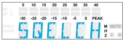
DISPL DiSPL
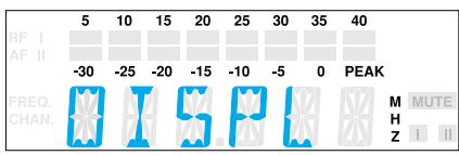
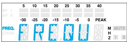
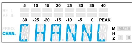
Selecting the content of the standard display
With all transmitters and receivers you can choose the content of the standard display i.e. whether the frequency or the channel number is displayed.
Select the "DISPL" menu by pressing the SET button until "DISPL" appears on the display; after a short pause the current setting is displayed.
With the / buttons you can now choose between:
Channel number: "CHANNEL"
Frequency: "FREQU"
The new setting for the standard display starts flashing on the display.
Press the SET button to return to the top menu level. The display then switches to the new standard display.
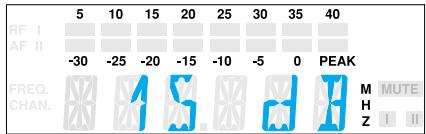
Configuring a frequency memory
Transmitters and receivers of the Sennheiser evolution wireless series ew 100 have 4 switchable frequencies(channels presets) respectively to store up to 4 transmission/receiving frequencies.
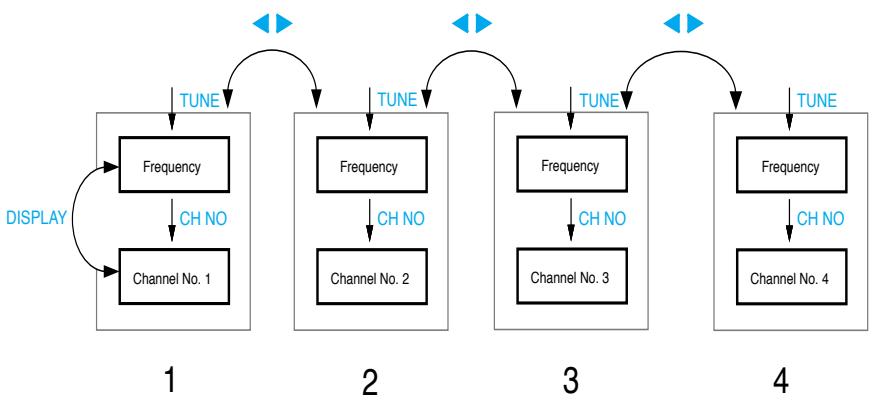
You can directly switch between the channels presets ("Selecting the frequency, channel number").
TUNetune
Setting the transmission/receiving frequency
Transmission and receiving frequencies are tunable in 25-kHz steps within a switching bandwidth of 32MHz max.
Special notes on multi-channel operation:
Several devices of the Sennheiser evolution wireless series ew 100 can be used simultaneously on different frequencies. The factory-preset frequencies are intermodulation-free. Before you program new frequency combinations, please refer to the information on the correct frequency choice given in the planning brochure "Practical Applications in RF Technology" which your local Sennheiser agent has in stock or will be pleased to order for you from Sennheiser.
Select the channel preset for which you wish to set a frequency.
Select the "TUNE" menu by pressing the SET button until "TUNE" appears on the display; after a short pause the currently set frequency is displayed.
With the / buttons you can now select a different frequency. The frequencies are tunable in 25-kHz steps. The new frequency starts flashing on the display and becomes effective immediately.
Press the SET button to return to the top menu level. The display then switches back to the standard display.
LOCK Loc
Activating/deactivating the lock-mode function
You can lock the / buttons and the ON/OFF button to prevent accidental programming or switching off during operation.
Activating the lock-mode function
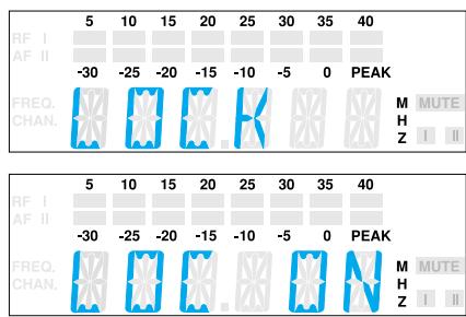
Select the "LOCK" menu by pressing the SET button. The current setting is indicated on the display.
Press the button to activate the lock-mode function. "LOC ON" starts flashing on the display.
Press the SET button to return to the top menu level.
Note:
If you press the / buttons or the ON/OFF button, "LOCK" appears on the display and the buttons are now locked.
Deactivating the lock-mode function
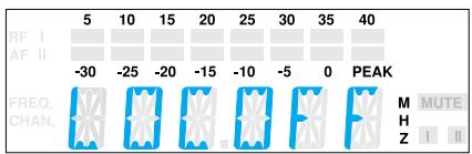
Select the "LOCK" menu by pressing the SET button. "LOC ON" appears on the display.
Press the button to deactivate the lock-mode function. "LOC OFF" begins to flash on the display.
Press the SET button to return to the top menu level. The display switches back to the standard display and the buttons can now be operated as usual.
7 Troubleshooting
Error checklist
| Problem | Possible cause |
| No operation indication | · Batteries are flat · No mains connection |
| No RF signal | · Transmission frequency is not the same as the receiving frequency · Transmitter is out of range |
| RF signal available | · Transmitter is muted ("MUTE") |
| but no audio signal | · Receiver's squelch threshold adjusted too high |
| Audio signal has a high level of background noise | · Transmitter sensitivity adjusted too low · Receiver's AF output level adjusted too low |
| Audio signal distorted | · Transmitter sensitivity adjusted too high · Receiver's AF output level adjusted too high |
If problems occur that are not listed in the above table, please contact your local Sennheiser agent for assistance.
Recommendations and tips
... for the ME 2 and ME 4 clip-on microphones
- To reduce level variations to a minimum when the user turns his or her head away from the microphone, attach the microphone as centrally as possible.
- To protect the microphone against excessive sweat/moisture, avoid direct skin contact.
- Attach the microphone carefully and conduct the cable such that noise due to friction is avoided.
- Always use the ME 4 directional microphone with a windshield and direct the microphone towards the sound source (e.g. mouth).
... for the ME 3 headmic
- Always use the microphone with a popshield and position the microphone at the corner of the mouth.
- You can vary the bass reproduction by increasing/decreasing the talking distance.
- Make sure that the sound inlet is directed towards the mouth. The sound inlet is marked with a little dot.
... for the SK 100 pocket transmitter
- Make sure that the antenna and the microphone cable do not cross.
- The antenna should hang freely and be at least 1cm away from the body. The antenna must not be in direct contact with the skin.
- For best results, make sure that the transmitter sensitivity is correctly adjusted.
... for the SKM 100 hand-held transmitter
- Hold the SKM 100 hand-held transmitter in the middle of the microphone body. Holding it close to the sound inlet basket will influence the microphone's pick-up pattern, holding it at the lower part of the body will reduce the transmitter's range.
- You can vary the bass reproduction by increasing/decreasing the talking distance.
- For best results, make sure that the transmitter sensitivity is correctly adjusted.
... for the EK 100 receiver
- The antenna should hang freely and be at least 1cm away from the body. The antenna must not be in direct contact with the skin. If the receiver is mounted onto a camera, we recommend using the A 17 helical antenna.
... for optimum reception
- Transmission range depends to a large extent on location and can vary from about 10m to about 150m . There should be a "free line of sight" between transmitting and receiving antennas.
- If, with the EM 100 receiver, reception conditions are unfavourable, you should use two remote antennas which are connected via antenna cable ("Accessories").
- To avoid overmodulating the receiver, observe a minimum distance of 5m between transmitting and receiving antennas.
- Observe a minimum distance of 50~cm between receiving antennas and metal objects (such as cross members or reinforced-concrete walls).
... for multi-channel operation
- You cannot use all adjustable frequency combinations simultaneously. The factory-preset frequencies (presets), however, are intermodulation-free. If you wish to program new frequency combinations, please contact your local Sennheiser agent who will provide you with information on the correct frequency choice.
- When using several transmitters simultaneously, interference can be avoided by maintaining a minimum distance of 20~cm between two transmitters.
- Use special accessories for multi-channel applications ("Accessories").
8 Care and maintenance
SKM 100 hand-held transmitter
The SKM 100's sound inlet basket should be cleaned from time to time.
Unscrew the inlet basket (turn counter-clockwise) and remove it.
Use a damp cloth to clean the inlet basket from the inside and outside. Note:
Do not use any cleasing agents or solvents. Do not touch the microphone's contacts.
Replace the inlet basket on the SKM 100 and screw it tight (taking care not to loose the coloured identification ring).
9 Overview
Wireless transmission systems
With the evolution wireless series, Sennheimer puts an end to cable tangles and enables complete freedom of movement at an affordable price.
The systems operate exclusively in the UHF band. UHF transmission is extremely reliable and is far less prone to interference than the overcrowded VHF band – harmonics from mains units, fluorescent tubes, refrigerators, computers, etc. are virtually eliminated. Also indoor propagation of UHF radio waves is better than VHF so that the RF power can be kept low – this is also an advantage when using multi-channel systems. Finally, UHF frequency ranges are being approved all over the world for radiomicrophone usage – in some countries licence-free.
There are three transmitter versions: The hand-held transmitter is a complete radiomicrophone in a single unit, the plug-on transmitter converts your favourite dynamic wired microphone into a radiomicrophone, the pocket transmitter can accept a wide range of inputs including: omnidirectional or cardioid "tie" microphones, head-worn microphone, guitar/instrument direct input and auxiliary devices via the optional CL 2 line input cable.
Fresh batteries ensure good transmission power during operation. Always use alkaline batteries for best operation - a 9V PP3 battery has a much longer operating time than a NiCd rechargeable battery (approx. 8 hours with a 9V PP3 or 1 hour with a rechargeable).
Correct adjustment of transmitter sensitivity is vital. Too high and you get overmodulation and distortion, too low and you get undermodulation and a noisy signal. Please set the sensitivity correctly for the microphone/usage and check it before every performance to ensure best operation.
Sennheiser miniature clip-on microphones can be attached in various ways: they can, for example, be attached to the hairline or to clothing (e.g. tie or lapel). However it is fixed, please make sure that the microphone is protected against sweat/ moisture and make-up.
Interference such as distortion, hissing or "birdying" may occur if several transmitters are used together and the frequencies have not been correctly chosen. Sennheiser standard frequencies (as supplied) are all intermodulation-free. For other frequency sets please contact your local Sennheiser agent, who will be able to provide you with information on correct frequency choice and/or be able to calculate special frequency sets for you.
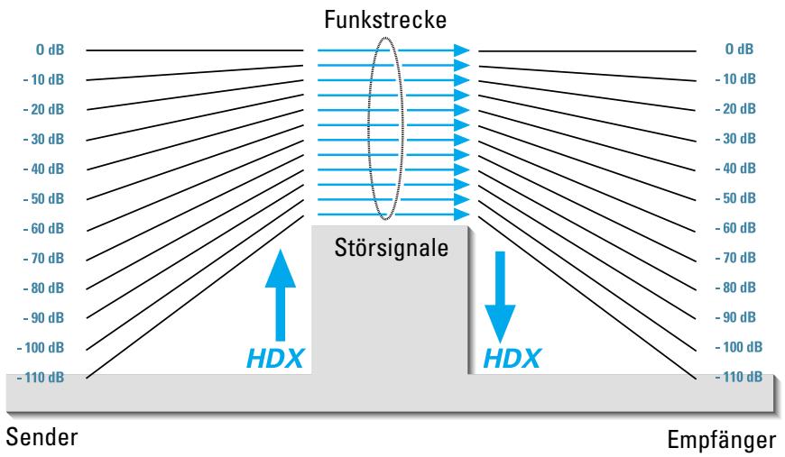
HDX noise reduction
Progress you can hear:
The evolution wireless Series is equipped with HDX, the new Sennheiser noise reduction system that reduces RF interference. It increases the signal-to-noise ratio in wireless audio transmission to up to 110 dB.
HDX is a wideband compander system which compresses the audio signal in the transmitter in a 2:1 ratio (related to dB) to lift it above the inherent noise floor of the RF link. A 110 dB dynamic range signal is thus transmitted with an effective dynamic range of only 55 dB, which is above the 60 dB noise floor of the RF link. In the receiver the signal is expanded in an identical and opposite way in a 1:2 ratio to restore the original signal, at the same time reducing the RF noise to below the noise floor of the receiver. Giving a radio link with a better signal-to-noise ratio than a CD.
HDX has been specially developed for high quality radiomicrophone systems.
Note:
Only transmitters and receivers that are equipped with HDX can work correctly with each other. If non HDX equipment was mixed with HDX, the dynamic range would be drastically reduced and the transmission would sound blunt and flat. HDX is permanently active and cannot be switched off.
Connector assignment
1/4" (6.3 mm) stereo jack plug (EM 100)
balanced unbalanced
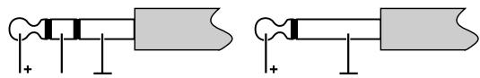
3.5 mm stereo jack plug (lockable) (SK 100)
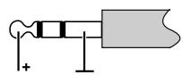
3.5 mm stereo jack plug (lockable) unbalanced
DC connector/Power supply
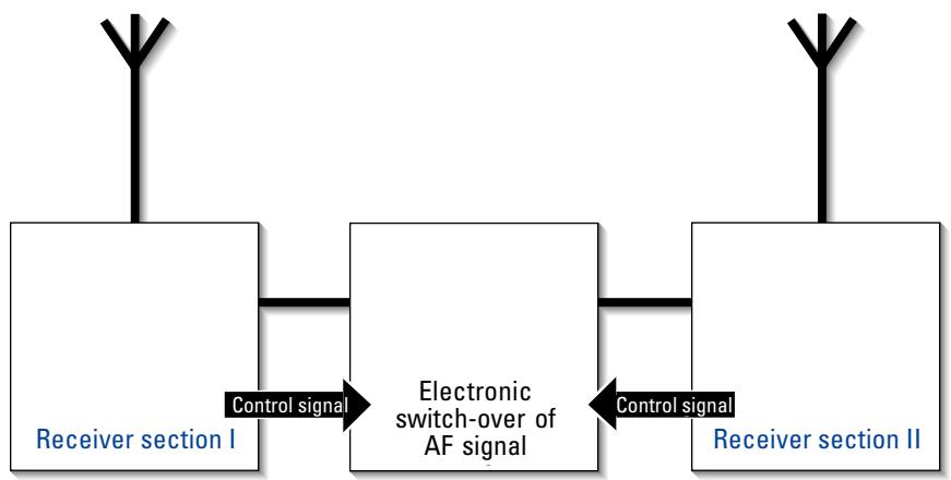
Diversity reception
The EM 100 receiver operates on the "true diversity" principle:
A receiving antenna receives not only the electromagnetic waves which reach it by a direct path, but also the reflections of these waves which are created in the room by walls, windows, ceilings and fittings. When these waves are superimposed, destructive interference occurs, which can also be called "field strength gaps". Repositioning the receiving antenna can bring a solution, provided the transmitter remains in its original position. With mobile transmitters, however (which all radiomicrophones are), the "field strength gap" will then occur with a different transmitter position. These "field strength gaps" can only be eliminated with true diversity receivers.
In true diversity, instead of one antenna and one receiver there are now two antennas and two receiver sections. The antennas are spatially separated. By means of a comparison circuit, the receiver section with the strongest RF signal is always switched to the common AF output. The risk of the occurrence of "field strength gaps" in both antennas at the same time is virtually nonexistent.
The receiver display panel shows the active diversity section (I or II).
Technical data
System
RF characteristics
Modulation
Frequency ranges
Transmission/receiving frequencies
Switching bandwidth
Frequency stability
AF characteristics
Noise reduction system
Nominal/peak deviation
AF frequency response
Signal-to-noise ratio at 1mV_RF
and peak deviation, HDx
THD at nom. deviation and 1kHz
Overall device
Temperature range
Dimensions Carrying case [mm]
Weight Carrying case with EM 100
Carrying case with EK 100
In compliance with
| wideband FM |
| 518 - 550, 630 - 662, 740 - 772, 790 - 822, 838 - 870 MHz |
| 1280, tunable in steps of 25 kHz |
| 4 switchable channels |
| 32 MHz |
| ≤ ± 15 ppm |
Sennheiser HDX
± 24kHz / ≤ ± 48kHz
60 - 18,000Hz
≥ 110 dB(A)
≤ 0.9%
-10°C ... +55°C
380× 370× 70
approx. 3100g
approx. 2200g
ETS 300 422, ETS 300 445 (CE), FCC
Receiver
RF characteristics
Receiver principle
Sensitivity (with HDX, peak deviation)
Squelch treshold
Antenna inputs
Antenna length [mm]
| EM 100 | EK 100 | |
| true diversity | non-diversity | |
| <2.5 μV at 52 dBArms S/N | ||
| 0-100 μV, adjustable | ||
| 2 BNC sockets | M3 thread | |
| Telescopic antennas | 518-550 MHz: | 130 |
| 630-662 MHz: | 110 | |
| 740-772 MHz: | 90 | |
| 790-822 MHz: | 90 | |
| 838-870 MHz: | 80 | |
| 50 Ω | ||
Antenna input impedance
AF characteristics
AF output voltage
at peak deviation 1kHz_AF
AF OUT
Level adjustment
| 1/4” (6.3 mm) jack socket: balanced: +10 dBu unbalanced: +4 dBu | 3.5 mm jack socket: unbalanced: +10 dBu |
| 0 - 40 dB |
Overall device
Power supply
Power consumption (operating time)
Dimensions [mm]
Weight
| EM 100 | EK 100 |
| 10.5-16 V DC, nominal voltage 12 V DC | 9 V PP3 battery (IEC 6 LR 61) |
| ≤ 200 mA | ≤ 75 mA (4-6 h) |
| 212 x 145 x 38 | 110 x 65 x 22 |
| approx. 1100 g | approx. 255 g |
Transmitters
RF characteristics
RF output power at 50
Antenna length [mm]
| SK 100 | SKP 100 | SKM 100 |
| typ. 30 mW | ||
| 518 - 550 MHz: 130 | ||
| 630 - 662 MHz: 110 | ||
| 740 - 772 MHz: 90 | ||
| 790 - 822 MHz: 90 | ||
| 838 - 870 MHz: 80 | ||
AF characteristics
Max. input voltage MICRO:
(at peak dev., 1kHz_AF LINE:
| 1.8 Vrms | 2.9 Vrms | - |
| 2.4 Vrms |
Overall device
Power supply
Max. power consumption at nom. voltage
Operating time
Dimensions [mm]
Weight
| 9 V alkaline PP3 battery (IEC 6 LR 61) | ||
| ≤ 60 mA | ||
| >8 h | >8 h | >8 h |
| 110 x 65 x 22 | 105 x 43 x 43 | Ø 50 x 225 |
| approx. 255 g | approx. 195 g | approx. 450 g |
Microphones
Transducer principle
Sensitivity
Sound pressure
Pick-up pattern
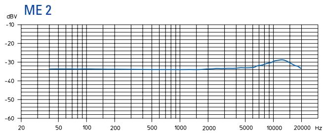
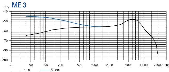
| ME 2 | ME 3 | ME 4 |
| condenser | condenser | condenser |
| 20 mV/Pa | 1.6 mV/Pa | 40 mV/Pa |
| 130 dB SPL | 150 dB SPL | 120 dB SPL |
| omni-directional | super-cardioid | cardioid |
Transducer principle
Sensitivity
Sound pressure
Pick-up pattern
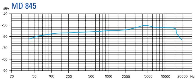
| MD 835 | MD 845 | ME 865 |
| dynamic | dynamic | condenser |
| 1.5 mV/Pa | 1 mV/Pa | 3 mV/Pa |
| 150 dB SPL | 154 dB SPL | 144 dB SPL |
| cardioid | super-cardioid | super-cardioid |
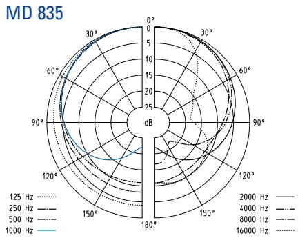
Polar diagrams of microphones/microphone modules
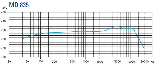
Frequency response curves of microphones/microphone modules
Accessories
MD 835 Microphone module for SKM 100, dynamic, cardioid
MD 845 Microphone module for SKM 100, dynamic, super-cardioid
ME 865 Microphone module for SKM 100, condenser, super-cardioid
MZW1 Wind-and popshield for SKM 100,
MZQ1 Microphone clamp for SKM 100
ME 2 Clip-on microphone for SK 100, condenser, omni-directional
ME 4 Clip-on microphone for SK 100, condenser, cardioid
ME3 Headmic for SK 100, condenser, super-cardioid
Cl 1 Instrument cable for SK 100, with 14 (6.3 mm) jack plug
CL2 Line input cable for SK 100, with female 3-pin XLR connector
GA1 19" rack adaptor for EM 100, for mounting two EM 100/ASP 1 or one EM 100/ASP 1 with AM 1 into a 19" rack
AM 1 Antenna mount for connecting antennas to the front of the GA 1
A 1031-U UHF antenna, passive, omni-directional, can be mounted onto a stand
AB 1-A UHF antenna booster, 518-550 MHz
AB 1-B 10 dB gain 630-662 MHz
AB 1-C (powered via ASP 1/NT 1) 740-772 MHz
AB 1-D 790-822 MHz
AB1-E 838-870MHz
GZL 1019-A1 / 5 / 10 Antenna cable with BNC connectors 1m / 5m / 10m
ASP 1 Antenna splitter
2 x 1:4, passive, for connecting four EM 100 to two A 1031-U/AB 1
NT 1 Plug-in mains unit for ASP 1 (to power four receivers and two AB 1)
DC 1 DC power adaptor, for external 12V DC powering of SK/EK 100 (instead of 9 V PP3 battery)
A 17-1 Helical antenna for EK 100, 518-662 MHz
A 17-2 for use with cameras 740-870 MHz
CC 1 Carrying case for SET ew 100
NOTICE D'EMPLOI
evolution wireless Série
Cw 100


1 Sommaire
Chap. Index
Page
Animations: -20/-10 dB
Interviews: -10/0 dB
588.588
-80.88
True Diversity | Non-Diversity
<2,5 V para 52 dB_AeffS/N
Regulable desde0hastra 100 V
| 2 conectores hembra BNC | Rosca M3 |
| 518 - 550 MHz: 130 | |
| 630 - 662 MHz: 110 | |
| 740 - 772 MHz: 90 | |
| 790 - 822 MHz: 90 | |
| 838 - 870 MHz: 80 |
Range B: 630-662 MHz,
Range C: 740-772 MHz,
Range D: 790 - 822 MHz,
Presentatic: -20 / -10 dB
Interview: -10/0 dB
584566
-4088