
WITUNE - Electronic tuner KORG - Free user manual and instructions
Find the device manual for free WITUNE KORG in PDF.
| Product Type | Wireless Electronic Tuner |
| Brand | KORG |
| Model | WITUNE |
| Dimensions (tuner) | 100 x 99 x 34 mm |
| Dimensions (transmitter) | 27 x 45 x 10 mm |
| Weight (tuner with batteries) | 204 g |
| Weight (transmitter with battery) | 11 g |
| Power Supply (tuner) | 2 AA batteries (alkaline recommended) |
| Power Supply (transmitter) | 1 CR2032 battery (Panasonic) |
| Battery Life (tuner) | Approx. 45 h (wireless mode with backlight) |
| Battery Life (transmitter) | Approx. 25 h (continuous A4 input) |
| Measurement Range | A0 (27.50 Hz) ~ C8 (4186.01 Hz) |
| Calibration Range | A4 = 410 ~ 480 Hz (1 Hz steps) |
| Measurement Accuracy | ±1 cent |
| Sound Accuracy | ±1.5 cents |
| Tuning Modes | Visual (AUTO) and Auditory (MANUAL) |
| Main Functions | Wireless tuning, built-in mic, backlight, visual mode, auditory mode |
| Wireless System | 2.4 GHz |
| Speaker | Dynamic (ø23 mm) |
| Included Accessories | AA batteries (x2), CR2032 battery (x1), normal clip WR-01, small clip WR-01, strap WR-01S, instruction manual |
| Operating Temperature | 0 ~ +40°C (non-condensing) |
| Maintenance | Clean with a dry, clean cloth. Do not use solvents. |
| Safety Instructions | Use appropriate batteries, avoid extreme exposure, do not open the housing |
| Compliance | European Directive 1999/5/EC, Canadian regulation NMB-003 Class B |
Frequently Asked Questions - WITUNE KORG
User questions about WITUNE KORG
0 question about this device. Answer the ones you know or ask your own.
Ask a new question about this device
Download the instructions for your Electronic tuner in PDF format for free! Find your manual WITUNE - KORG and take your electronic device back in hand. On this page are published all the documents necessary for the use of your device. WITUNE by KORG.
USER MANUAL WITUNE KORG
Using the unit in the following locations can result in a malfunction.
In direct sunlight
- Locations of extreme temperature or humidity
- Excessively dusty or dirty locations
- Locations of excessive vibration
- Close to magnetic fields
Power supply
Be sure to turn the power switch to OFF when the unit is not in use. Remove the battery in order to prevent it from leaking when the unit is not in use for extended periods.
Interference with other electrical devices
Radios and televisions placed nearby may experience reception interference. Operate this unit at a suitable distance from radios and televisions.
Handling
To avoid breakage, do not apply excessive force to the switches or controls.
Care
If the exterior becomes dirty, wipe it with a clean, dry cloth. Do not use liquid cleaners such as benzene or thinner, or cleaning compounds or flammable polishes.
Keep this manual
After reading this manual, please keep it for later reference.
Keeping foreign matter out of your equipment
Never set any container with liquid in it near this equipment. If liquid gets into the equipment, it could cause a breakdown, fire, or electrical shock. Be careful not to let metal objects get into the equipment.
CAUTION
Risk of Explosion if Battery is replaced by an incorrect type. Dispos. of used batteries according to the instructions.
THE FCC REGULATION WARNING (for USA)
This equipment has been tested and found to comply with the limits for a Class B digital device, pursuant to Part 15 of the FCC Rules. These limits are designed to provide reasonable protection against harmful interference in a residential installation. This equipment generates, uses, and can radiate radio frequency energy and, if not installed and used in accordance with the instructions, may cause harmful interference to radio communications. However, there is no guarantee that interference will not occur in a particular installation. If this equipment does cause harmful interference to radio or television reception, which can be determined by turning the equipment off and on, the user is encouraged to try to correct the interference by one or more of the following measures:
Reorient or relocate the receiving antenna.
- Increase the separation between the equipment and receiver.
- Connect the equipment into an outlet on a circuit different from that to which the receiver is connected.
- Consult the dealer or an experienced radio/TV technician for help. Unauthorized changes or modification to this system can void the user's authority to operate this equipment.
This device complies with Part 15 of the FCC Rules. Operation is subject to the following two conditions: (1) This device may not cause harmful interference, and (2) this device must accept any interference received, including interference that may cause undesired operation.
Complies with Canadian ICES-003 Class B.
Operation is subject to the following two conditions :
(1) this device may not cause interference, and
(2) this device must accept any interference, including interference that may cause undesired operation of the device.
The installer of this radio equipment must ensure that the antenna is located or pointed such that it does not emit RF field in excess of Health Canada limits for the general population; consult Safety Code 6, obtainable from Health Canada's website www.hc-sc.gc.ca/rpb
CALIFORNIA USA ONLY
This Perchlorate warning applies only to primary CR (Manganese Dioxide) Lithium coin cells sold or distributed ONLY in California USA. "Perchlorate Material-special handling may apply. See www.dtsc.ca.gov/hazardouswaste/perchlorate."
European Union Directives Conformance Statement
Korg Inc. hereby declares that the product meets the requirements of Directive 1999/5/EC. You can view the Declaration of Conformity(Doc) to Directive 1999/5/EC in the Owner's Manual of this product posted on the Korg website (www.korg.com).


Notice regarding disposal (EU only)

When this "crossed-out wheeled bin" symbol is displayed on the product, owner's manual, battery, or battery package, it signifies that when you wish to dispose of this product, manual, package or battery you must do so in an approved manner. Do not discard this product, manual, package or battery along with ordinary household waste. Disposing in the correct manner will prevent harm to human health and potential damage to the environment. Since the correct method of disposal will depend on the applicable laws and regulations in your locality, please

contact your local administrative body for details. If the battery contains heavy metals in excess of the regulated amount, a chemical symbol is displayed below the "crossed-out wheeled bin" symbol on the battery or battery package.
IMPORTANT NOTICE TO CONSUMERS
This product has been manufactured according to strict specifications and voltage requirements that are applicable in the country in which it is intended that this product should be used. If you have purchased this product via the internet, through mail order, and/or via a telephone sale, you must verify that this product is intended to be used in the country in which you reside.
WARNING: Use of this product in any country other than that for which it is intended could be dangerous and could invalidate the manufacturer's or distributor's warranty.
Please also retain your receipt as proof of purchase otherwise your product may be disqualified from the manufacturer's or distributor's warranty.
Thank you for purchasing the Korg Wi-Tune Wireless Tuner. To help you get the most out of your new tuner, please read this manual carefully.
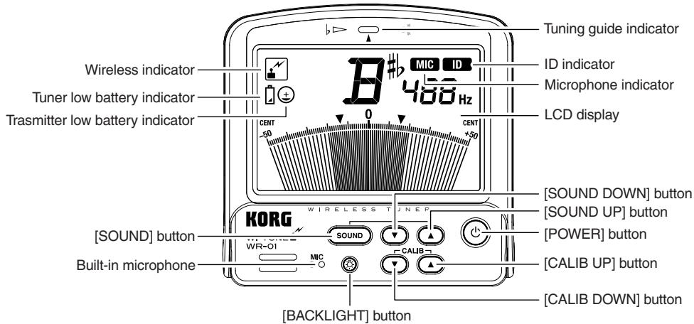
Part names
Tuner
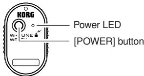
Transmitter
Installing batteries
Before you install or replace the batteries on your Tuner or Transmitter, be sure to turn off the power to both the transmitter as well as the tuner. The batteries that are included are intended to allow you to check functionality and may have a short life.
If the batteries for the Tuner or Transmitter are low on power, the low battery indicator will appear on the LCD display of the Tuner. Both units will continue to work for a while, but tuning may not be accurate. Please replace the batteries with new ones as soon as possible.
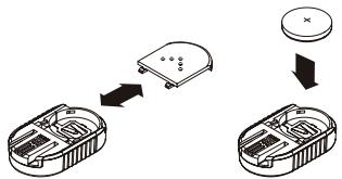
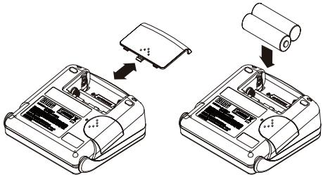
Installing batteries in the Tuner
- Gently press down and slide the battery case cover on the rear panel of the Tuner to remove it.
- Properly orient the batteries and insert them into the unit. (Alkaline batteries recommended)

3. Reattach the battery cover on the Tuner.
Please don't charge an alkaline battery.
Installing batteries in the Transmitter
CR2032 batteries that are compatible with the Transmitter
CR2032 batteries made by Panasonic
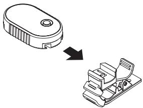
- Remove the clip that's attached to the Transmitter, then gently press down and slide the battery case cover on the near panel of the Transmitter to remove it.
- Properly orient the battery and insert it into the unit.
- Reattach the battery cover on the Transmit-ter.
Attaching and removing the supplied clip/strap on the Transmitter
Insert the clip or strap into the clip attachment groove on the Transmitter and slide it in all the way. Make sure that you insert the clip or strap in the correct orientation.
To remove the clip or strap, hold the Transmitter securely and slide the clip or strap while holding it by its sides.
When you attach the clip do not touch the connectors on the Transmitter.
Do not pull the clip by grasping the pinching portion of the clip. Otherwise, the clip or strap may break.
When you attach the clip or strap, be sure to slide it in all the way until it is locked, then make sure that it's secure.
Attaching the Transmitter to your musical instrument
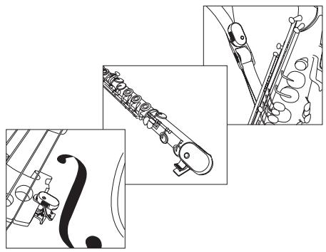
The Wi-Tune measures the pitch of a musical instrument by sensing vibrations from the instrument. These vibrations are picked up by the Transmitter, and wirelessly transmitted to the Tuner. However, depending where the Transmitter is attached to the instrument, the vibrations may not be picked up very well. In this case, try repositioning the Transmitter to pick up these vibrations better.
The Transmitter can be attached to musical instruments such as woodwind, brass or strings instruments. With some musical instruments, such as a saxophone, you can attach the Transmitter to a strap or other part that vibrates, rather than directly to the instrument itself.
Please refer to the attachment position examples that are shown in the figures to the right.
When you clip the Transmitter to or remove it from the musical instrument, handle it gently. Attaching the Transmitter to the musical instrument for a long period of time may leave a trace on the instrument.
Applying excessive force to the Transmitter or clip may cause damage.
Transmitter attachment position examples
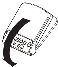
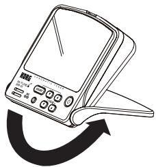
Using the Tuner stand
Setting the ID after replacing the Transmitter
The ID setting data is shared by the Tuner and Transmitter. This is done to prevent signal scramble during wireless communication. An ID was programmed into the Tuner and Transmitter supplied in this Wi-Tune package before they shipped from the factory. If you are using a different Transmitter (that was not included in this package), you must set the ID on that Transmitter.
- Gently press down and slide the cover on the right side of the Tuner to remove it.
- Slide the Transmitter into the Tuner so that the Transmitter will lock into the Tuner's connector.
- Turn on the power to the Transmitter and Tuner.
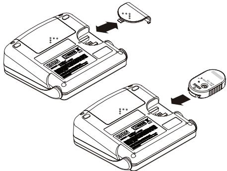

You can do this while the power to each unit is turned on.
When the transmission of the ID data from the Transmitter to the Tuner is complete, the ID indicator will light up on the LCD.
4. After the ID data is transmitted, remove the Transmitter from the Tuner.
The ID indicator on the LCD will turn off.
If multiple Wi-Tune units are used in the same location, the tuning meter may not respond to the proper instrument, or an incorrect note name may be displayed. In such cases, resetting the ID will restore communication between the Transmitter and Tuner.
If there is no input sound for 20 minutes while the Transmitter is turned on, or if the Transmitter and Tuner cannot communicate with each other for two minutes, the power will automatically be turned off.
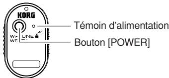
Turning the power on and off
- Press the [POWER] button on the Tuner and Transmitter to turn the power on and off.
If there is no input sound for 20 minutes while the Tuner is turned on, the power will automatically be turned off.
Backlight
- Press the [BACK LIGHT] button. The LCD backlight will turn on.
Pressing the [BACK LIGHT] button will turn the LCD backlight on and off.
Wireless tuning
Once the power to the Tuner and Transmitter is turned on and communication becomes possible, the built-in microphone of the Tuner will turn off, enabling you to use the wireless function. At this time, the wireless indicator will appear on the LCD.
Tuning via wireless microphone
You can use the built-in microphone on the Tuner by only turning on the power to the Tuner. At this time, the MIC indicator on the LCD will turn on.
Once wireless tuning is enabled, the Tuner will maintain wireless tuning mode even if it is unable to receive a signal because the power to the Transmitter is turned off, the batteries on the Transmitter are exhausted, or the Transmitter is moved outside the range of communication. If you want to switch the Tuner to microphone tuning mode, turn off the power to both the Tuner and Transmitter, then turn on the power to the Tuner only.
Meter mode
Meter mode enables you to tune your instrument by looking at the meter and using the Transmitter or the built-in microphone of the Tuner. In this mode, you can perform either wireless tuning or tuning with the built-in microphone of the Tuner.
- Press the [CALIB UP] button or the [CALIB DOWN] button to select the reference pitch.
You can adjust the reference pitch in 1Hz steps in the range of 410Hz to 480Hz .
- Play a single note on your musical instrument to tune.
The Tuner displays the name of the note closest to the recognized pitch. Tune your instrument so that the Tuner displays the note name that you are turning to.
- Play a single note again and tune your instrument so that the tuning guide indicator (the center of the meter) will turn on.
When you are using the Tuner's built-in microphone for tuning, try to avoid allowing sounds from sources other than the instrument to be picked up by the microphone.
Even within the measurable range, a note with lots of harmonics or a quick decay may not be measurable (e.g., especially notes in the extreme bass or treble range of the piano).
To raise a pitch by a pure major 3rd or a pure minor 3rd, adjust the tuning so that the meter needle will point to the pure major or minor 3rd mark respectively. For example, if you want to raise the note of A (0 cent) by a pure major 3rd, first tune your instrument so that the display will indicate the note name C#, then fine-tune the instrument so that the meter needle will point the down arrow (-13.7 cents) on the left side of the meter. If you want to raise the note of A (0 cent) by a pure minor 3rd, tune your instrument so that the display will indicate note name C, then fine-tune the instrument so that the meter needle will point the up arrow (+15.6 cents) on the right side of the meter.
Sound-out mode
In this mode, you can tune your instrument by referring to the oscillator sound at the reference pitch (output from the speaker of the Tuner).
-
Press the [SOUND] button to engage sound-out mode.
-
Press the [SOUND UP] or [SOUND DOWN] button to select the name of the note that you want to tune to.
You can select a pitch in the range of C4 (261.63Hz) to C5 (523.25Hz).
- Tune your instrument while referring to the oscillator sound at the reference pitch output from the Tuner.
- To exit Sound-out mode, press the [SOUND] button.
Specifications
Operating temperature: 0 + 40^ / +32 + 104^ (non-condensing)
Temperament: Equal temperament
Measurement range: A0 (27.50Hz) - C8 (4186.01Hz)
Reference pitch: C4 (261.63Hz) - C5 (523.25Hz); One octave
Tuning mode: Meter mode (AUTO),Sound-out mode (MANUAL)
Calibration range: A4 = 410 - 480Hz (1Hz steps)
Measurement precision: Within ± 1 cent
Sound precision: Within ± 1.5 cents
Wireless: 2.4GHz band
Speaker: Dynamics speaker ( 23mm)
Power: Tuner; AA batteries (x2) = 3V (Alkaline batteries recommended)
Transmitter; CR2032 batteries made by Panasonic
Dimensions (W x D x H):Tuner; 100 x 99 x 34mm / 3.94 x 3.90 x 1.34inches
Transmitter; 27 × 45 × 10 ~mm / 1.06 × 1.77 × 0.39 inches
Regular clip (WR-01); 56 × 22 × 47 ~mm / 2.20 × 0.87 × 1.85 inches
Small clip (WR-01); 44 × 17 × 24 ~mm / 1.73 × 0.67 × 0.94 inches
Strap (WR-01S); Length about 50cm / 19.69inches
Maximum width about 40mm / 1.57inches
Weight: Tuner; 204g / 7.20oz. (including batteries)
Transmitter; 11g / 0.39oz (including batteries)
Regular clip (WR-01); 11g / 0.39oz.
Small clip (WR-01); 5g / 0.18oz
Strap (WR-01S); about 65g / 2.29oz
Battery life: Tuner; Approx. 45hours (during wireless tuning operation with backlight on) Transmitter; Approx. 25hours (continuous A4 input operation)
Accessories: Owner's Manual; AA batteries (x2) and CR2032 lithium battery (3V) (x1) for checking operation; Regular clip (WR-01), Small clip (WR-01) or Strap (WR-01S) for attaching to the musical instrument.
- Specifications and appearance are subject to change without notice for improvement.
Précautions
Emplacement

Description
Accordeur
Transmetteur
Installation des piles
Normaler Clip (WR-01); 11g
Kleiner Clip (WR-01); 5g
Gurt (WR-01S); Ungefahr 65g
- Gently press down and slide the battery case cover on the rear panel of the Afinador to remove it.
- Properly orient the batteries and insert them into the unit. (recomendado baterias alcalinas)
- Play a single note on your musical instrument to tune.
Clip normal (WR-01); 11g
Clip pequeno (WR-01); 5g
Correa (WR-01S); Aproximadamente 65g
Vida de la bateria:
Date of issue: February 22, 2010
Declaration of Conformity
Manufacturer KORG INC.
Address : 4015-2 Yanokuchi, Inagi-City, Tokyo 206-0812 Japan.
Brand Name : KORG
Description of Device : WIRELESS TUNER
Model No. : WR-01
Power Supply DC 3V (Battery)
Power Consumption : -
Fulfils the essential requirements of the Directive 1999/5/EC (R&TTE).
The following standards were applied:
RF: ETSI EN 300 440-1 V1.5.1(2009-03)
Electromagnetic compatibility and Radio spectrum Matters(ERM); Short range devices; Radio equipment to be used in the 1 GHz to 40 GHz frequency range; Part 1: Technical characteristics and test methods
RF: ETSI EN 300 440-2 V1.3.1(2009-03)
Electromagnetic compatibility and Radio spectrum Matters(ERM); Short range devices; Radio equipment to be used in the 1 GHz to 40 GHz frequency range; Part 2: Harmonized EN covering essential requirements of article 3.2 of the R&TTE Directive
EMC: ETSI EN 301 489-1 V1.8.1(2008-04)
Electromagnetic compatibility and Radio spectrum Matters(ERM); ElectroMagnetic Compatibility(EMC) standard for radio equipment and services; Part 1: Common technical requirements
EMC: ETSI EN 301 489-3 V1.4.1(2002-08)
Electromagnetic compatibility and Radio spectrum Matters(ERM); ElectroMagnetic Compatibility(EMC) standard for radio equipment and services; Part 3: Specific conditions for Short-Range Devices(SRD) operating on frequencies between 9 kHz and 40 GHz
Health: EN 50371(2002)
Generic standard to demonstrate the compliance of low power electronic and electrical apparatus with the basic restrictions related to human exposure to electromagnetic fields(10 MHz - 300 MHz) -General public.
Safety: EN 60950-1: 2006, 2nd Edition+A11: 2009
Information technology equipment -Safety- Part 1: General Requirements
Remarks:
Authorized Representative
Korg UK LTD
9 NEWMARKET COURT, KINGSTON, MILTON KEYNES, MK10 0AU, U.K.
Signature: K. m2rokawa
Name: Koichi Miokawa
Title: Senior Engineer of Safety Standard Group Quality Assurance Sec.
CE affixed on 02/2010
Date of issue: February 22, 2010
Declaration of Conformity
Manufacturer KORG INC.
Address : 4015-2 Yanokuchi, Inagi-City, Tokyo 206-0812 Japan.
Brand Name : KORG
Description of Device : WIRELESS TUNER
Model No. : WR-TX
Power Supply DC 3V (Battery)
Power Consumption : -
Fulfils the essential requirements of Directive 1999/5/EC (R&TTE).
The following standards were applied:
RF: ETSI EN 300 440-1 V1.5.1(2009-03)
Electromagnetic compatibility and Radio spectrum Matters(ERM); Short range devices; Radio equipment to be used in the 1 GHz to 40 GHz frequency range; Part 1: Technical characteristics and test methods
RF: ETSI EN 300 440-2 V1.3.1(2009-03)
Electromagnetic compatibility and Radio spectrum Matters(ERM); Short range devices; Radio equipment to be used in the 1 GHz to 40 GHz frequency range; Part 2: Harmonized EN covering essential requirements of article 3.2 of the R&TTE Directive
EMC:ETSI EN 301489-1V1.8.1(2008-04)
Electromagnetic compatibility and Radio spectrum Matters(ERM); ElectroMagnetic Compatibility(EMC) standard for radio equipment and services; Part 1: Common technical requirements
EMC:ETSI EN 301489-3V1.4.1(2002-08)
Electromagnetic compatibility and Radio spectrum Matters(ERM); ElectroMagnetic Compatibility(EMC) standard for radio equipment and services; Part 3: Specific conditions for Short-Range Devices(SRD) operating on frequencies between 9kHz and 40GHz
Health: EN 50371(2002)
Generic standard to demonstrate the compliance of low power electronic and electrical apparatus with the basic restrictions related to human exposure to electromagnetic fields(10 MHz - 300 MHz) –General public.
Safety: EN 60950-1: 2006, 2nd Edition + A11: 2009
Information technology equipment -Safety- Part 1: General Requirements
Remarks:
Authorized Representative
Korg UK LTD
9 NEWMARKET COURT, KINGSTON, MILTON KEYNES, MK10 0AU, U.K.
Signature: K,m2tkaw2 .
Name: Koichi Miokawa
Title: Senior Engineer of Safety Standard Group Quality Assurance Sec.
CE affixed on 02/2010
- Power supply
- Interference with other electrical devices
- Handling
- Care
- Keep this manual
- Keeping foreign matter out of your equipment
- CAUTION
- THE FCC REGULATION WARNING (for USA)
- CALIFORNIA USA ONLY
- European Union Directives Conformance Statement
- Notice regarding disposal (EU only)
- IMPORTANT NOTICE TO CONSUMERS
- Installing batteries
- Installing batteries in the Tuner
- Reattach the battery cover on the Tuner.
- Installing batteries in the Transmitter
- Attaching and removing the supplied clip/strap on the Transmitter
- Attaching the Transmitter to your musical instrument
- Transmitter attachment position examples
- Using the Tuner stand
- Setting the ID after replacing the Transmitter
- After the ID data is transmitted, remove the Transmitter from the Tuner.
- Turning the power on and off
- Backlight
- Wireless tuning
- Tuning via wireless microphone
- Meter mode
- Sound-out mode
- Specifications
- Précautions
- Emplacement
- Installation des piles
- Declaration of Conformity
Brand : KORG
Model : WITUNE
Category : Electronic tuner