
NWA1100, NWA1100-N, NWA1121NI, NWA1123-NI - Wireless Access Point ZYXEL - Free user manual and instructions
Find the device manual for free NWA1100, NWA1100-N, NWA1121NI, NWA1123-NI ZYXEL in PDF.


| Product type | Wireless access point |
| Brand | ZYXEL |
| Models | NWA1100, NWA1100-N, NWA1121NI, NWA1123-NI |
| Power supply | 12 VDC adapter or Power over Ethernet (PoE) |
| Wireless standards | 802.11b/g |
| Frequency | 2.4 GHz |
| Maximum speed | Up to 54 Mbps (802.11g) |
| Ports | 1 Ethernet port 10/100 Mbps |
| Antennas | 2 removable antennas (RP-SMA connectors) |
| Wireless security | WEP, WPA, WPA2-PSK |
| Maximum number of clients | 32 |
| Management | Web interface (HTTP/HTTPS) |
| Default password | 1234 |
| Default IP address | 192.168.1.2 |
| LED indicators | SYS (green/amber), Ethernet (speed and activity) |
| Mounting | Desktop or wall (screws not included) |
| PoE power | Yes (via injector or PoE switch) |
| Reset | Reset button (restores factory settings) |
Frequently Asked Questions - NWA1100, NWA1100-N, NWA1121NI, NWA1123-NI ZYXEL
User questions about NWA1100, NWA1100-N, NWA1121NI, NWA1123-NI ZYXEL
0 question about this device. Answer the ones you know or ask your own.
Ask a new question about this device
Download the instructions for your Wireless Access Point in PDF format for free! Find your manual NWA1100, NWA1100-N, NWA1121NI, NWA1123-NI - ZYXEL and take your electronic device back in hand. On this page are published all the documents necessary for the use of your device. NWA1100, NWA1100-N, NWA1121NI, NWA1123-NI by ZYXEL.
USER MANUAL NWA1100, NWA1100-N, NWA1121NI, NWA1123-NI ZYXEL
802.11g Business WLAN Access Point
Firmware v1.00
Edition 1, 07/2008
DEFAULT LOGIN DETAILS
| IP Address: | http://192.168.1.2 |
| Password: | 1234 |
CONTENTS
| ENGLISH | 3 |
| DEUTSCH | 19 |
| ESPAÑOL | 35 |
| FRANÇAIS | 51 |
| ITALIANO | 67 |
| PYCCKIЙ | 83 |
| SVENSKA | 99 |
| 简体中文 | 115 |
| 繁體中文 | 129 |
natural_image
Technical line drawing of a dual-wire device with ventilation slots and a central ventilation chamber (no text or symbols)ZyXEL
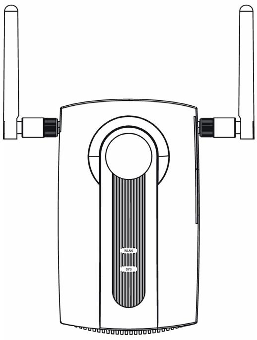
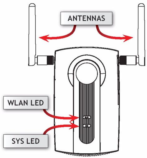
Front and Base Panels
Overview
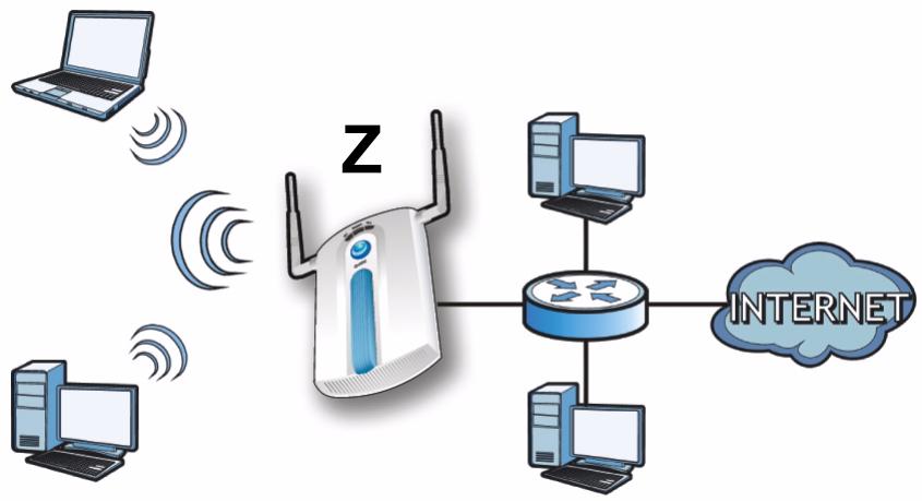
This Quick Start Guide shows how to set up and configure the NWA1100 (marked Z in the figure) to allow wireless clients to securely access your wired network. See your User's Guide for more information.
flowchart
graph TD
    A["Router"] --> B["Computer"]
    A --> C["Internet"]
    D["Laptop"] -->|Wireless Signal| A
    E["Computer"] -->|Wireless Signal| A
    F["Computer"] -->|Wireless Signal| A
    G["Computer"] -->|Wireless Signal| A
You may need your Internet access information.
To set up your wireless network you need to:
- Connect the Hardware
- Access the Web Configurator
- Configure the NWA1100
• Install the Hardware
- Set Up Power over Ethernet (Optional)
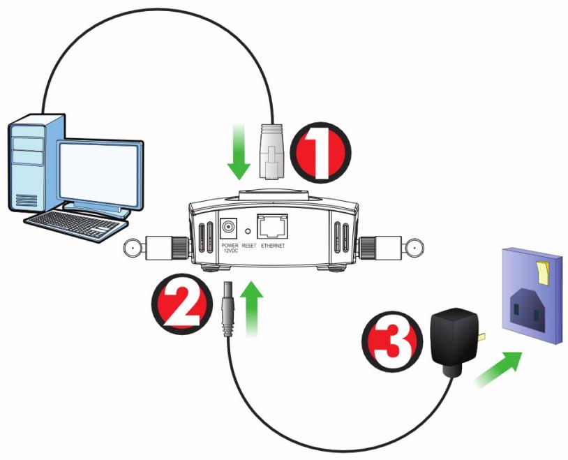
Connect the Hardware
flowchart
graph TD
    A["Computer"] --> B["Power RESET Ethernet 12VDC"]
    B --> C["Switch"]
    C --> D["Home Appliance"]
    D --> E["Switch"]
    E --> F["Switch"]
    style A fill:#f9f,stroke:#333
    style B fill:#ccf,stroke:#333
    style C fill:#cfc,stroke:#333
    style D fill:#fcc,stroke:#333
    style E fill:#cff,stroke:#333
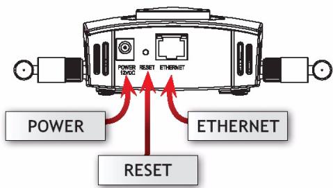
- Using the grey Ethernet cable, connect the ETHERNET port to a computer for initial configuration.
- Connect the POWER 12VDC socket to a power source using only the included power adaptor.
Connect the NWA1100's ETHERNET port to an Ethernet jack with network access after you have completed the initial configuration.
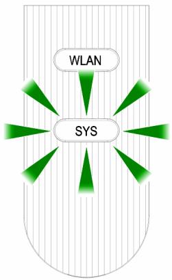
LEDs
flowchart
graph TD
    A["WLAN"] --> B["SYS"]
    B --> C["Green Arrow 1"]
    B --> D["Green Arrow 2"]
    B --> E["Green Arrow 3"]
    B --> F["Green Arrow 4"]
- The SYS LED blinks amber, then turns steady green when the power is connected.
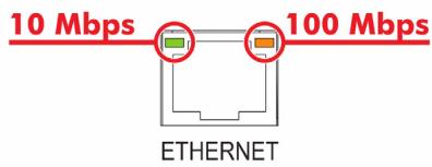
- One of the LEDs by the ETHERNET port turns on if the port is properly connected, and blinks when there is traffic. The amber light shines if the connection is at 100 Mbps. The green light shines if the connection is at 10Mbps.

If neither LED near the ETHERNET port turns on, check the cable connections to the port. Ensure your computer's network card is working properly.
Access the Web Configurator
Use Internet Explorer 6.0 and later or Netscape Navigator 7.0 and later versions with JavaScript enabled and pop-up blocking disabled.
Set Up Your Computer's IP Address
Note down your computer's current IP settings before you change them.
First, set your computer to use a static IP address in the 192.168.1.3 - 192.168.1.254 range with a subnet mask of 255.255.255.0. This ensures that your computer can communicate with your NWA1100. See your User's Guide for information on setting up your computer's IP address.
Log Into the Web Configurator
Even though you can connect to the NWA1100 wirelessly, it is recommended that you connect your computer to the ETHERNET port for initial configuration.
- Launch your web browser. Enter 192.168.1.2 (the NWA1100's default IP address) as the address.


If you cannot access the Web configurator, make sure the IP addresses and subnet masks of the NWA1100 and the computer are in the same IP address range.
- Enter 1234 (the default password) in the Password field and click Login.
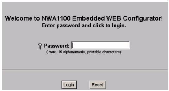
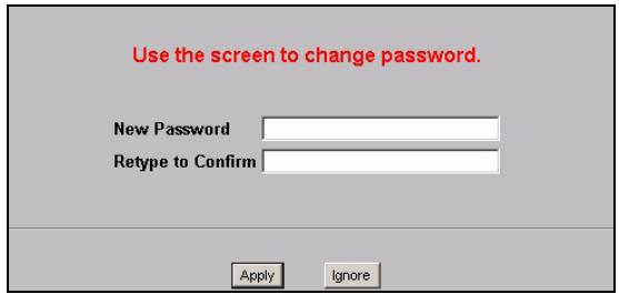
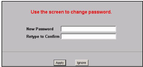
- Change the login password by entering a new password and clicking Apply. Be sure to record the new password and keep it in a safe place.
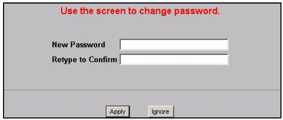

If you change the password and then forget it, you will need to reset the NWA1100. Refer to the User's Guide for how to use the RESET button.
- The STATUS screen appears.
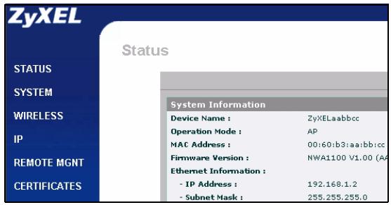
Configure the NWA1100
Configure System Settings
1. Click SYSTEM in the navigation panel.
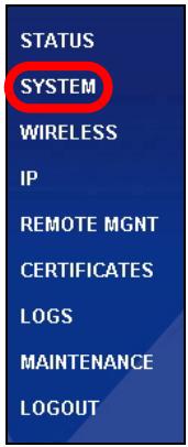
2. The SYSTEM > General screen appears.
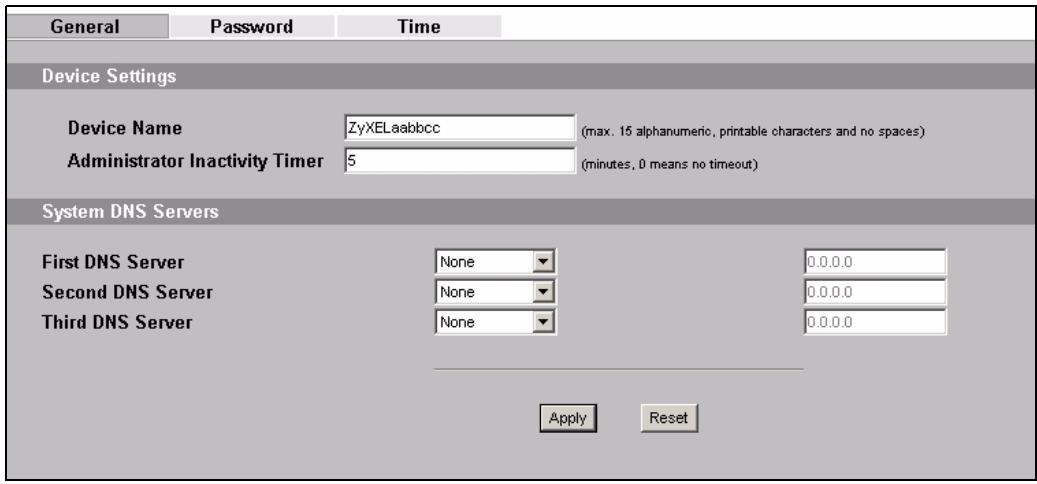
System Name is for identifying the NWA1100 on your network. Choose a distinctive name, or leave this at its default.
DNS Server(s): if your ISP gave you specific DNS (Domain Name System) settings, select User-Defined and enter them here. Otherwise, leave these fields at their defaults.
3. Click Apply.
Configure Wireless Settings
- Click WIRELESS in the navigation panel. The Wireless Settings screen displays.
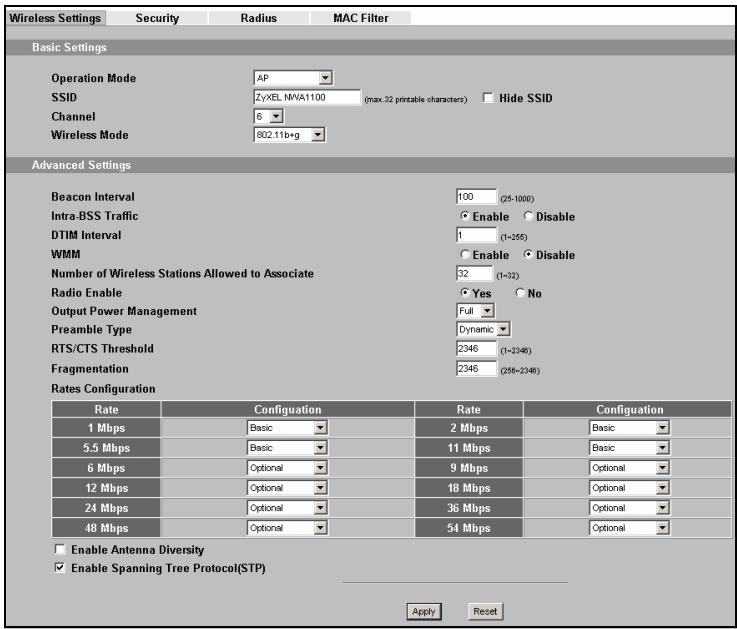
The wireless stations and the NWA1100 must use the same SSID, channel ID and encryption settings for wireless communication.
Operation Mode: Ensure that AP mode is selected.
Wireless Mode: Select the wireless standard you want your network to use. If you are not sure which to select, select 802.11b+g.
Channel: Select the wireless channel you want your network to use.
-
Click Apply to save your settings.
-
Click the Security tab. If you don't configure wireless security, anyone can access your network.
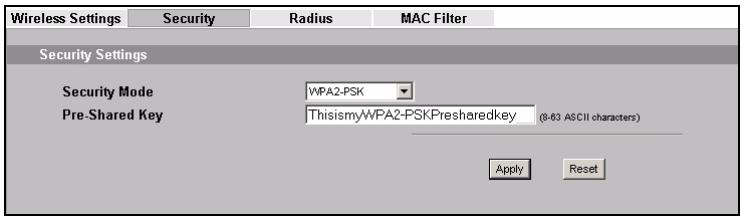
This is where you can enter the security settings for your wireless network. The fields you fill in differ according to the type of security you select in the Security Mode field. Select None if you do not wish to use wireless security.
This example uses WPA2-PSK security, in which all wireless clients must use the same pre-shared key to join the network.
Ensure that all your wireless clients support the type of security you set. Click Apply when you have finished.

If the wireless clients cannot communicate with the network, ensure that the clients and the NWA1100 are using the same wireless security settings.
Configure IP Settings
- You need to set your NWA1100's IP address to be in the same subnet as your network. Click IP in the navigation panel.
Select Get automatically from DHCP if you want to have a DHCP server on your network assign an IP address to the NWA1100.
If you have a specific IP address to use, select Use fixed IP address and enter it along with the subnet mask and gateway IP address.
Click Apply. The NWA1100 now uses the new IP settings; you can no longer connect to the NWA1100 using the default IP address.
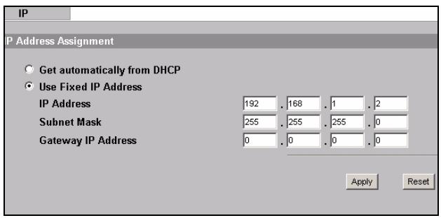
If you change the NWA1100's IP address, you must use the new IP address when you next access the web configurator. If you select Get automatically from DHCP, check your DHCP server to determine the IP address it assigns to the NWA1100. Refer to your DHCP server's documentation for more information.
- If you changed your computer's IP address, return it to its previous setting.
- Change the wireless settings in the wireless stations to match those of the NWA1100, if necessary. Refer to your wireless adapter's documentation.
The NWA1100 is now ready to connect to your switch or router. You can do this now, or once you have attached the antennas and mounted the NWA1100.

If the NWA1100 cannot communicate with the network, ensure that the NWA1100 is using an IP address on the same subnet as the switch / router.
Install the Hardware
Figures in this section use generic icons. The ZyXEL Device in the picture is not an exact representation of your device.
Attaching Antennas
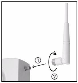
Screw the antennas clockwise onto the antenna connectors on the sides of your NWA1100. The antennas should be perpendicular to the ground and parallel to each other.
Make sure the antennas are securely screwed onto the antenna connectors.
natural_image
Close-up of a white antenna with a pin and base, showing a rotation arrow (no text or symbols)Hardware Mounting
In general, the best location for the access point is at the center of your intended wireless coverage area. For better performance, mount the NWA1100 high up in an area that is free of obstructions.
Wall-mounting
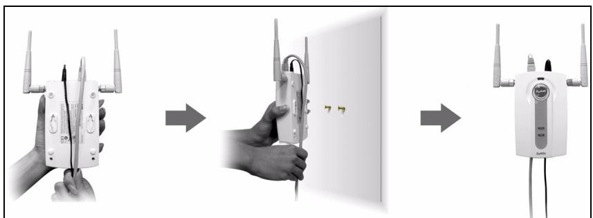
Do the following to attach your NWA1100 to a wall.
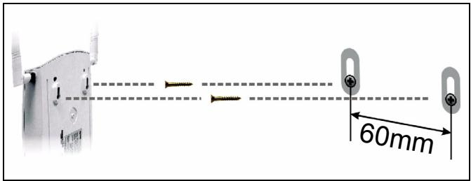
- Screw the two screws provided with your NWA1100 into the wall 60mm apart (see the figure in step 3). Use screws with 6mm \~ 8mm (0.24" \~ 0.31") wide heads. Do not screw the screws all the way in to the wall; leave a small gap between the head of the screw and the wall.
The gap must be big enough for the screw heads to slide into the screw slots and the connection cables to run down the back of the NWA1100.
Make sure the screws are securely fixed to the wall and strong enough to hold the weight of the NWA1100 with the connection cables.
2. Adjust the cables.
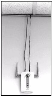
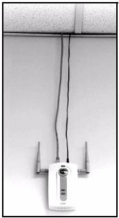
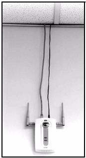
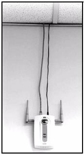
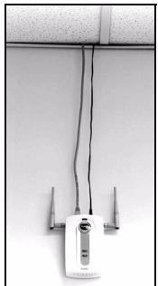
Run the connection cables down the back of the NWA1100 as shown in the following figure.
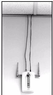
OR:
Run the connection cables upward and along the edge of the ceiling.
flowchart
graph LR
    A["Hand holding RF controller"] --> B["Add to wall-mounted device"]
    B --> C["Add to wireless router with 7-segment display"]
natural_image
Close-up of a wireless router mounted on a wall, connected to three antennas (no visible text or symbols)- Align the holes on the back of the NWA1100 with the screws on the wall. Hang the NWA1100 on the screws.
Set Up Power over Ethernet (Optional)
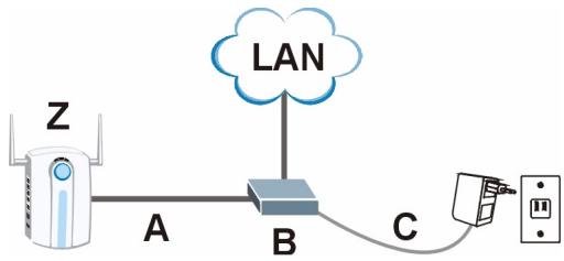
Power over Ethernet (PoE) is the ability to provide power to your NWA1100 via an 8-pin CAT 5 Ethernet cable, eliminating the need for a nearby power source.
A PoE injector (not included) is also needed to supply the Ethernet cable with power. This feature allows increased flexibility in the location of your NWA1100.
In the following figure, Z is your NWA1100, A is the CAT 5 Ethernet cable, B is the PoE injector and C is the power cable.
flowchart
graph TD
    A["Router"] -->|A| B["Network"]
    B -->|B| C["Router"]
    C -->|C| D["Router"]
    D --> E["Switch"]
    style A fill:#f9f,stroke:#333
    style B fill:#ccf,stroke:#333
    style C fill:#cfc,stroke:#333
    style D fill:#fcc,stroke:#333
    style E fill:#ffc,stroke:#333
Übersicht


flowchart
graph LR
    A["Hand holding wireless devices"] --> B["Switched to wall-mounted device"]
    B --> C["Device mounted on wall-mounted device with 77 microphones"]


flowchart
graph LR
    A["Hand holding wireless devices"] --> B["Switching device with 7-segment display"]
    B --> C["Device with 7-segment display"]
natural_image
Close-up of a white electronic device with wires and connectors against a plain wall (no visible text or symbols)

Montage du matériel
flowchart
graph LR
    A["Hand holding wireless devices"] --> B["Switching device with 7-segment display"]
    B --> C["Device with 7-segment display"]
natural_image
Close-up of a white electronic device with wires and connectors against a plain wall (no visible text or symbols)

flowchart
graph LR
    A["Hand holding wireless devices"] --> B["Switching device with 7-segment display"]
    B --> C["Device with 7-segment display"]
natural_image
Close-up of a white electronic device with wires and connectors against a plain wall (no visible text or symbols)

Монтаж оборудования
natural_image
Close-up of a white electronic device with wires and connectors against a plain wall (no visible text or symbols)

Montera maskinvara
flowchart
graph LR
    A["Hand holding wireless devices"] --> B["Switched to wall-mounted device"]
    B --> C["Device mounted on wall-mounted device with 77 microphones"]


硬件安装
natural_image
Close-up of a white electronic device with three antennas connected by wires against a plain wall (no visible text or symbols)

硬體安裝
flowchart
graph LR
    A["Person holding RF device"] --> B["Hand holding RF device"]
    B --> C["Switch 7.7"]
    C --> D["Switch 8.0"]
    D --> E["Switch 9.0"]
natural_image
Pure white background with a blue horizontal bar at the top (no text or symbols)- 802.11g Business WLAN Access Point
- Front and Base Panels
- Overview
- You may need your Internet access information.
- Connect the Hardware
- LEDs
- Access the Web Configurator
- Set Up Your Computer's IP Address
- Log Into the Web Configurator
- Configure the NWA1100
- Configure System Settings
- Click SYSTEM in the navigation panel.
- The SYSTEM > General screen appears.
- Click Apply.
- Configure Wireless Settings
- Configure IP Settings
- Install the Hardware
- Attaching Antennas
- Hardware Mounting
- Wall-mounting
- Adjust the cables.
- Set Up Power over Ethernet (Optional)
- Übersicht
- Montage du matériel
- Монтаж оборудования
- Montera maskinvara
- 硬件安装
- 硬體安裝
Brand : ZYXEL
Model : NWA1100, NWA1100-N, NWA1121NI, NWA1123-NI
Category : Wireless Access Point