
WAC6103D-I - Wireless Access Point ZYXEL - Free user manual and instructions
Find the device manual for free WAC6103D-I ZYXEL in PDF.
| Product Type | Wireless Access Point |
| Brand | ZYXEL |
| Model | WAC6103D-I |
| Wireless Standards | IEEE 802.11a/b/g/n/ac |
| Frequency Bands | 2.4 GHz (2400-2483.5 MHz) and 5 GHz (5150-5850 MHz) |
| Maximum Data Rate | Up to 1.9 Gbps (AC1900) |
| Number of Antennas | 4 internal PIFA/dipole antennas |
| Network Connectivity | 1 Gigabit Ethernet port with PoE |
| Power Supply | PoE 802.3af/at |
| Power Consumption | Less than 15 W |
| Mounting | Ceiling or wall |
| Dimensions (diameter x height) | 200 x 38 mm (estimated) |
| Weight | 350 g (estimated) |
| Operating Temperature | 0°C to 50°C |
| Operating Humidity | 10% to 90% non-condensing |
| Wireless Security | WEP, WPA, WPA2, WPA3 |
| Management | Zyxel Controller or standalone web interface |
| Certifications | CE, IC, FCC |
| Warranty | 2 years |
| Box Contents | Access point, mounting kit, quick start guide |
Frequently Asked Questions - WAC6103D-I ZYXEL
User questions about WAC6103D-I ZYXEL
0 question about this device. Answer the ones you know or ask your own.
Ask a new question about this device
Download the instructions for your Wireless Access Point in PDF format for free! Find your manual WAC6103D-I - ZYXEL and take your electronic device back in hand. On this page are published all the documents necessary for the use of your device. WAC6103D-I by ZYXEL.
USER MANUAL WAC6103D-I ZYXEL
natural_image
Abstract geometric illustration of two stylized buildings with blue and white outlines, no text or symbols presentIMPORTANT!
READ CAREFULLY BEFORE USE.
KEEP THIS GUIDE FOR FUTURE REFERENCE.
This is a User's Guide for a series of products. Not all products support all firmware features. Screenshots and graphics in this book may differ slightly from your product due to differences in your product firmware or your computer operating system. Every effort has been made to ensure that the information in this manual is accurate.
Related Documentation
- Quick Start Guide
The Quick Start Guide shows how to connect the NWA/WAC and access the Web Configurator.
• CLI Reference Guide
The CLI Reference Guide explains how to use the Command-Line Interface (CLI) and CLI commands to configure the NWA/WAC.
Note: It is recommended you use the Web Configurator to configure the NWA/WAC.
• Web Configurator Online Help
Click the help icon in any screen for help in configuring that screen and supplementary information.
- More Information
Go to support.zyxel.com to find other information on the NWA/WAC.

Contents Overview
User's Guide 10
Introduction 11
The Web Configurator 29
Technical Reference 41
Dashboard 42
Monitor 48
Network 60
Wireless 69
User 81
AP Profile 88
MON Profile 108
WDS Profile 112
Certificates 114
System 131
Log and Report 156
File Manager 169
Diagnostics 180
LEDs 182
Antenna Switch 185
Reboot 187
Shutdown 188
Troubleshooting 189
Table of Contents
Contents Overview ....3
Table of Contents 4
Part I: User's Guide....10
Chapter 1
Introduction....11
1.1 Overview ...... 11
1.1.1 Management Mode 13
1.1.2 MBSSID 13
1.1.3 Dual-Radio 14
1.1.4 Root AP 15
1.1.5 Repeater 16
1.2 Ways to Manage the NWA/WAC 17
1.3 Good Habits for Managing the NWA/WAC 17
1.4 Hardware Connections ...... 17
1.5 NWA5301-NJ Hardware 18
1.5.1 110 Punch-Down Block .... 18
1.5.2 Phone Port 19
1.5.3 Console Port 19
1.6 LEDs 20
1.6.1 WAC6502D-E, WAC6502D-S, and WAC6503D-S 21
1.6.2 NWA1123-AC PRO and WAC6103D-I 22
1.6.3 NWA5301-NJ 24
1.6.4 NWA1123-ACv2, NWA5121-N, NWA5121-NI, NWA5123-AC and NWA5123-NI ..... 25
1.6.5 WAC5302D-S 26
1.7 Starting and Stopping the NWA/WAC 27
Chapter 2
The Web Configurator....29
2.1 Overview 29
2.2 Accessing the Web Configurator 29
2.3 Navigating the Web Configurator 30
2.3.1 Title Bar 31
2.3.2 Navigation Panel 34
2.3.3 Warning Messages 37
2.3.4 Tables and Lists 37
Part II: Technical Reference.... 41
Chapter 3
Dashboard....42
3.1 Overview 42
3.1.1 What You Can Do in this Chapter 42
3.2 Dashboard 42
3.2.1 CPU Usage 46
3.2.2 Memory Usage 47
Chapter 4
Monitor 48
4.1 Overview 48
4.1.1 What You Can Do in this Chapter 48
4.2 What You Need to Know 48
4.3 Network Status 49
4.4 Radio List 50
4.4.1 AP Mode Radio Information 51
4.5 Station List 53
4.6 WDS Link Info 54
4.7 Detected Device 55
4.8 View Log 56
Chapter 5
Network....60
5.1 Overview 60
5.1.1 Management Mode 60
5.1.2 What You Can Do in this Chapter 62
5.2 IP Setting 63
5.3 VLAN 64
5.4 AC (AP Controller) Discovery 67
Chapter 6
Wireless 69
6.1 Overview 69
6.1.1 What You Can Do in this Chapter 69
6.1.2 What You Need to Know .... 70
6.2 AP Management 70
6.3 MON Mode 73
6.3.1 Add/Edit Rogue/Friendly List 74
6.4 Load Balancing 75
6.4.1 Disassociating and Delaying Connections 77
6.5 DCS 78
6.6 Technical Reference 78
Chapter 7
User....81
7.1 Overview 81
7.1.1 What You Can Do in this Chapter 81
7.1.2 What You Need To Know 81
7.2 User Summary 82
7.2.1 Add/Edit User 82
7.3 Setting 84
7.3.1 Edit User Authentication Timeout Settings 86
Chapter 8
AP Profile......88
8.1 Overview 88
8.1.1 What You Can Do in this Chapter 88
8.1.2 What You Need To Know 88
8.2 Radio 89
8.2.1 Add/Edit Radio Profile 90
8.3 SSID 95
8.3.1 SSID List 95
8.3.2 Add/Edit SSID Profile 96
8.4 Security List 98
8.4.1 Add/Edit Security Profile 99
8.5 MAC Filter List 103
8.5.1 Add/Edit MAC Filter Profile 103
8.6 Layer-2 Isolation List 104
8.6.1 Add/Edit Layer-2 Isolation Profile 106
Chapter 9
MON Profile....108
9.1 Overview 108
9.1.1 What You Can Do in this Chapter 108
9.2 MON Profile 108
9.2.1 Add/Edit MON Profile 109
9.3 Technical Reference 110
Chapter 10
WDS Profile 112
10.1 Overview 112
10.1.1 What You Can Do in this Chapter 112
10.2 WDS Profile 112
10.2.1 Add/Edit WDS Profile 113
Chapter 11
Certificates 114
11.1 Overview 114
11.1.1 What You Can Do in this Chapter 114
11.1.2 What You Need to Know 114
11.1.3 Verifying a Certificate 116
11.2 My Certificates 117
11.2.1 Add My Certificates .... 118
11.2.2 Edit My Certificates .... 121
11.2.3 Import Certificates 124
11.3 Trusted Certificates 125
11.3.1 Edit Trusted Certificates 126
11.3.2 Import Trusted Certificates ...... 129
11.4 Technical Reference 130
Chapter 12
System....131
12.1 Overview 131
12.1.1 What You Can Do in this Chapter 131
12.2 Host Name 131
12.3 Date and Time 132
12.3.1 Pre-defined NTP Time Servers List 135
12.3.2 Time Server Synchronization 135
12.4 WWW Overview 136
12.4.1 Service Access Limitations 136
12.4.2 System Timeout 136
12.4.3 HTTPS 137
12.4.4 Configuring WWW Service Control 137
12.4.5 HTTPS Example 139
12.5 SSH 146
12.5.1 How SSH Works 146
12.5.2 SSH Implementation on the NWA/WAC 147
12.5.3 Requirements for Using SSH 148
12.5.4 Configuring SSH 148
12.5.5 Examples of Secure Telnet Using SSH 148
12.6 Telnet 150
12.7 FTP 150
12.8 SNMP 151
12.8.1 Supported MIBs 152
12.8.2 SNMP Traps 153
12.8.3 Configuring SNMP 153
12.8.4 Adding or Editing an SNMPv3 User Profile 154
Chapter 13
Log and Report......156
13.1 Overview 156
13.1.1 What You Can Do In this Chapter 156
13.2 Email Daily Report 156
13.3 Log Setting 158
13.3.1 Log Setting Screen 159
13.3.2 Edit System Log Settings 160
13.3.3 Edit Remote Server 163
13.3.4 Active Log Summary 165
Chapter 14
File Manager 169
14.1 Overview 169
14.1.1 What You Can Do in this Chapter 169
14.1.2 What you Need to Know 169
14.2 Configuration File 170
14.2.1 Example of Configuration File Download Using FTP 174
14.3 Firmware Package 175
14.3.1 Example of Firmware Upload Using FTP 176
14.4 Shell Script 177
Chapter 15
Diagnostics 180
15.1 Overview 180
15.1.1 What You Can Do in this Chapter 180
15.2 Diagnostics 180
Chapter 16
LEDs 182
16.1 Overview 182
16.1.1 What You Can Do in this Chapter 182
16.2 Suppression Screen 182
16.3 Locator Screen 183
Chapter 17
Antenna Switch....185
17.1 Overview 185
17.1.1 What You Need To Know 185
17.2 Antenna Switch Screen 185
Chapter 18
Reboot....187
18.1 Overview 187
18.1.1 What You Need To Know 187
18.2 Reboot 187
Chapter 19
Shutdown 188
19.1 Overview 188
19.1.1 What You Need To Know 188
19.2 Shutdown 188
Chapter 20
Troubleshooting....189
20.1 Overview 189
20.2 Power, Hardware Connections, and LED 189
20.3 NWA/WAC Access and Login 190
20.4 Internet Access 191
20.5 Wireless Connections 192
20.6 Resetting the NWA/WAC 197
20.7 Getting More Troubleshooting Help 198
Appendix A Importing Certificates 199
Appendix B IPv6.... 212
Appendix C Customer Support 220
Appendix D Legal Information 226
Index 237
PART I
User's Guide
CHAPTER 1 Introduction
1.1 Overview
This User's Guide covers the following models: NWA1123-ACv2, NWA5121-N, NWA5121-NI, NWA5123-AC, NWA5123-NI, NWA5301-NJ, NWA1123-AC PRO, WAC5302D-S, WAC6502D-E, WAC6502D-S, WAC6503D-S, WAC6553D-E and WAC6103D-I. Your NWA/WAC is a wireless AP (Access Point). It extends the range of your existing wired network without additional wiring, providing easy network access to mobile users.
Table 1 NWA Series Comparison Table
| FEATURES | NWA1123-ACv2 | NWA5121-N | NWA5121-NI | NWA5123-AC | NWA5123-NI | NWA5301-NJ | NWA1123-AC PRO |
| Supported Wireless Standards | IEEE 802.11aIEEE 802.11bIEEE 802.11gIEEE 802.11nIEEE 802.11ac | IEEE 802.11bIEEE 802.11gIEEE 802.11n | IEEE 802.11bIEEE 802.11gIEEE 802.11n | IEEE 802.11aIEEE 802.11bIEEE 802.11gIEEE 802.11nIEEE 802.11ac | IEEE 802.11aIEEE 802.11bIEEE 802.11gIEEE 802.11n | IEEE 802.11bIEEE 802.11gIEEE 802.11n | IEEE 802.11aIEEE 802.11bIEEE 802.11gIEEE 802.11nIEEE 802.1IAC |
| Supported Frequency Bands | 2.4 GHz5 GHz | 2.4 GHz | 2.4 GHz | 2.4 GHz5 GHz | 2.4 GHz5 GHz | 2.4 GHz | 2.4 GHz5 GHz |
| Available Security Modes | NoneWEPWPA2WPA2-MIXWPA2-PSKWPA2-PSK-MIX | NoneWEPWPA2WPA2-MIXWPA2-PSKWPA2-PSK-MIX | NoneWEPWPA2WPA2-MIXWPA2-PSKWPA2-PSK-MIX | NoneWEPWPA2WPA2-MIXWPA2-PSKWPA2-PSK-MIX | NoneWEPWPA2WPA2-MIXWPA2-PSKWPA2-PSK-MX | NoneWEPWPA2WPA2-MIXWPA2-PSKWPA2-PSK-MIX | NoneWEPWPA2WPA2WPA-MIXWPA-PSKWPA2-PSK-MIX |
| Number of SSID Profiles | 32 | 32 | 32 | 32 | 32 | 32 | 32 |
| Number of Wireless Radios | 2 | 1 | 1 | 2 | 2 | 1 | 2 |
| Monitor Mode & Rogue APs Detection | Yes | Yes | Yes | Yes | Yes | No | Yes |
| WDS (Wireless Distribution System) - Root AP & Repeater Modes | Yes | Yes | Yes | Yes | Yes | Yes | Yes |
| Layer-2 Isolation | Yes | Yes | Yes | Yes | Yes | Yes | Yes |
| Power Detection | No | No | No | No | No | No | No |
| External Antennas | No | Yes | No | No | No | No | No |
| Internal Antenna | Yes | No | Yes | Yes | Yes | Yes | Yes |
| Antenna Switch | No | No | No | No | No | No | Yes |
| 802.11r Fast Roaming Support in Managed AP Mode | No | Yes | Yes | Yes | Yes | Yes | No |
| Maximum number of log messages | 512 event logs or 1024 debug logs | ||||||
Table 2 WAC Series Comparison Table
| FEATURES | WAC5302D-S | WAC6502D-E | WAC6502D-S | WAC6503D-S | WAC6553D-E | WAC6103D-I |
| Supported Wireless Standards | IEEE 802.11aIEEE 802.11bIEEE 802.11gIEEE 802.11nIEEE 802.11ac | IEEE 802.11aIEEE 802.11bIEEE 802.11gIEEE 802.11nIEEE 802.11ac | IEEE 802.11aIEEE 802.11bIEEE 802.11gIEEE 802.11nIEEE 802.11ac | IEEE 802.01aIEEE 802.11bIEEE 802.11gIEEE 802.11nIEEE 802.11ac | IEEE 802.11aIEEE 802.11bIEEE 802.11gIEEE 802.11nIEEE 802.11ac | IEEE 802.11aIEEE 802,11bIEEE 802.11gIEEE 802.11nIEEE 802.11ac |
| Supported Frequency Bands | 2.4 GHz5 GHz | 2.4 GHz5 GHz | 2.4 GHz5 GHz | 2.4 GHz5 GHz | 2.4 GHz5 GHz | 2.4 GHz5 GHz |
| Available Security Modes | NoneWEPWPA2WPA2-MIXWPA2-PSKWPA2-PSK-MIX | NoneWEPWPA2WPA2-MIXWPA2-PSKWPA2-PSK-MIX | NoneWEPWPA2WPA2-MIXWPA2-PSKWPA2-PSK-MIX | NoneWEPWPA2WPA2-MIXWPA2-PSKWPA2-PSK-MIX | NoneWEPWPA2WPA2-MIXWPA2-PSKWPA2-PSK-MIV | NoneWEPWPA2WPA2-MIXWPA2-PSKWPA2-PSK-MIX |
| Number of SSID Profiles | 32 | 32 | 32 | 32 | 32 | 32 |
| Number of Wireless Radios | 2 | 2 | 2 | 2 | 2 | 2 |
| Monitor Mode & Rogue APs Detection | No | Yes | Yes | Yes | Yes | Yes |
| WDS (Wireless Distribution System) - Root AP & Repeater Modes | No | Yes | Yes | Yes | Yes | Yes |
| Layer-2 Isolation | Yes | Yes | Yes | Yes | Yes | Yes |
| Power Detection | Yes | Yes | Yes | Yes | Yes | No |
| External Antennas | No | Yes | No | No | Yes | No |
| Internal Antenna | Yes | No | Yes | Yes | No | Yes |
| Antenna Switch | No | No | No | No | No | Yes |
| 802.11r Fast Roaming Support in Managed AP Mode | No | Yes | Yes | Yes | Yes | Yes |
| Maximum number of log messages | 512 event logs or 1024 debug logs | |||||
You can set the NWA/WAC to operate in either standalone AP or managed AP mode. When the NWA/WAC is in standalone AP mode, it can serve as a normal AP, as an RF monitor to search for rouge APs to help eliminate network threats (if it supports monitor mode and rogue APs detection), or even as a root AP or a wireless repeater to establish wireless links with other APs in a WDS (Wireless Distribution System). A WDS is a wireless connection between two or more APs.
Your NWA/WAC's business-class reliability, SMB features, and centralized wireless management make it ideally suited for advanced service delivery in mission-critical networks. It uses Multiple BSSID and VLAN to provide simultaneous independent virtual APs. Additionally, innovations in roaming technology and QoS features eliminate voice call disruptions.
The NWA/WAC controls network access with Media Access Control (MAC) address filtering, and rogue Access Point (AP) detection. It also provides a high level of network traffic security, supporting IEEE 802.1x, Wi-Fi Protected Access 2 and Wired Equivalent Privacy (WEP) data encryption.
Your NWA/WAC is easy to install, configure and use. The embedded Web-based configurator enables simple, straightforward management and maintenance. See the Quick Start Guide for how to make hardware connections.
1.1.1 Management Mode
The NWA/WAC is a unified AP and can work either in standalone AP mode or in managed AP mode. If the NWA/WAC and a Zyxel AP controller, such as the NXC2500 or NXC5500, are in the same subnet, it will be managed by the controller automatically.
An AP controller uses Control And Provisioning of Wireless Access Points (CAPWAP, see RFC 5415) to discover and configure multiple managed APs.
To set the NWA/WAC to be managed by an AP controller in a different subnet or change between management modes, use the AC (AP Controller) Discovery screen (see Section 5.4 on page 67).
Table 3 NWA/WAC Management Mode Comparison
| MANAGEMENT MODE | DEFAULT IP ADDRESS | UPLOAD FIRMWARE VIA |
| Standalone AP | Dynamic or Static (192.168.1.2) | Web Configurator or FTP |
| Managed AP | Dynamic | CAPWAP or FTP |
When the NWA/WAC is in standalone AP mode and connects to a DHCP server, it uses the IP address assigned by the DHCP server. Otherwise, the NWA/WAC uses the default static management IP address (192.168.1.2). You can use the AC Discovery screen to have the NWA/WAC work as a managed AP.
When the NWA/WAC is in managed AP mode, it acts as a DHCP client and obtains an IP address from the AP controller. It can be configured ONLY by the AP controller. To change the NWA/WAC back to standalone AP mode, use the Reset button to restore the default configuration. Alternatively, you need to check the AP controller for the NWA/WAC's IP address and use FTP to upload the default configuration file at conf/system-default.conf to the NWA/WAC and reboot the device.
1.1.2 MBSSID
A Basic Service Set (BSS) is the set of devices forming a single wireless network (usually an access point and one or more wireless clients). The Service Set IDentifier (SSID) is the name of a BSS. In Multiple BSS (MBSSID) mode, the NWA/WAC provides multiple virtual APs, each forming its own BSS and using its own individual SSID profile.
You can configure multiple SSID profiles, and have all of them active at any one time.
You can assign different wireless and security settings to each SSID profile. This allows you to compartmentalize groups of users, set varying access privileges, and prioritize network traffic to and from certain BSSs.
To the wireless clients in the network, each SSID appears to be a different access point. As in any wireless network, clients can associate only with the SSIDs for which they have the correct security settings.
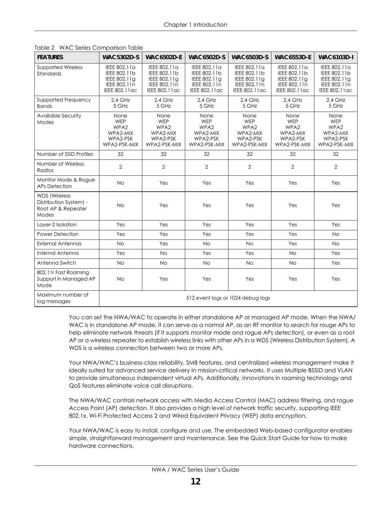
For example, you might want to set up a wireless network in your office where Internet telephony (VoIP) users have priority. You also want a regular wireless network for standard users, as well as a 'guest' wireless network for visitors. In the following figure, VoIP_SSID users have QoS priority, SSID01 is the wireless network for standard users, and Guest_SSID is the wireless network for guest users. In this example, the guest user is forbidden access to the wired Land Area Network (LAN) behind the AP and can access only the Internet.
Figure 1 Multiple BSSs
flowchart
graph TD
    A["LAN"] --> B["Internet"]
    B --> C["VoIP_SSID"]
    B --> D["SSID01"]
    B --> E["Guest_SSID"]
    B --> F["Data Bus Icon"]
    style A fill:#cce5ff,stroke:#333
    style B fill:#ffe6cc,stroke:#333
    style C fill:#e6f7ff,stroke:#333
    style D fill:#e6f7ff,stroke:#333
    style E fill:#e6f7ff,stroke:#333
    style F fill:#ffe6cc,stroke:#333
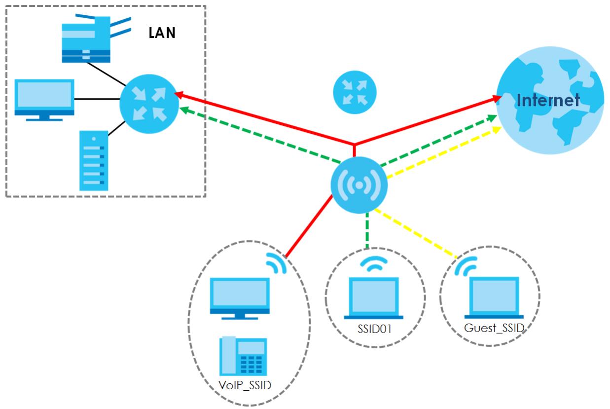
1.1.3 Dual-Radio
Some of the NWA/WAC models are equipped with dual wireless radios. This means you can configure two different wireless networks to operate simultaneously.
Note: A different channel should be configured for each WLAN interface to reduce the effects of radio interference.
You could use the 2.4 GHz band for regular Internet surfing and downloading while using the 5 GHz band for time sensitive traffic like high-definition video, music, and gaming.
Figure 2 Dual-Radio Application
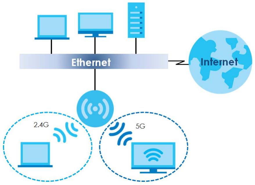
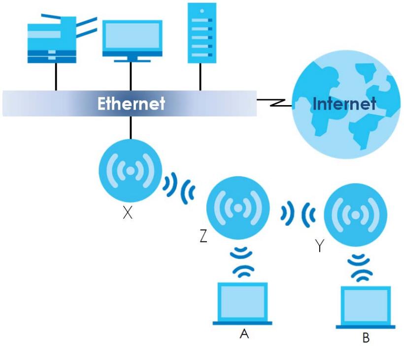
In Root AP mode, the NWA/WAC (Z) can act as the root AP in a wireless network and also allow repeaters (X and Y) to extend the range of its wireless network at the same time. In the figure below, both clients A, B and C can access the wired network through the root AP.
Figure 3 Root AP Application
flowchart
graph TD
    A["Internet"] --> B["Ethernet"]
    B --> C["X"]
    B --> D["Y"]
    B --> E["Z"]
    B --> F["A"]
    B --> G["B"]
    B --> H["C"]
On the NWA/WAC in Root AP mode, you can have multiple SSIDs active for regular wireless connections and one SSID for the connection with a repeater (repeater SSID). Wireless clients can use either SSID to associate with the NWA/WAC in Root AP mode. A repeater must use the repeater SSID to connect to the NWA/WAC in Root AP mode.
When the NWA/WAC is in Root AP mode, repeater security between the NWA/WAC and other repeater is independent of the security between the wireless clients and the AP or repeater. When repeater security is enabled, both APs and repeaters must use the same pre-shared key. See Section 6.2 on page 70 and Section 10.2 on page 112 for more details.
Unless specified, the term “security settings” refers to the traffic between the wireless clients and the AP. At the time of writing, repeater security is compatible with the NWA/WAC only.
1.1.5 Repeater
The NWA/WAC can act as a wireless network repeater to extend a root AP's wireless network range, and also establish wireless connections with wireless clients.
Using Repeater mode, your NWA/WAC can extend the range of the WLAN. In the figure below, the NWA/WAC in Repeater mode (Z) has a wireless connection to the NWA/WAC in Root AP mode (X) which is connected to a wired network and also has a wireless connection to another NWA/WAC in Repeater mode (Y) at the same time. Z and Y act as repeaters that forward traffic between associated wireless clients and the wired LAN. Clients A and B access the AP and the wired network behind the AP through repeaters Z and Y.
Figure 4 Repeater Application
flowchart
graph TD
    A["Ethernet"] --> B["X"]
    A --> C["Z"]
    A --> D["Y"]
    A --> E["B"]
    B --> F["Internet"]
    C --> F
    D --> F
    E --> F
When the NWA/WAC is in Repeater mode, repeater security between the NWA/WAC and other repeater is independent of the security between the wireless clients and the AP or repeater. When repeater security is enabled, both APs and repeaters must use the same pre-shared key. See Section 6.2 on page 70 and Section 10.2 on page 112 for more details.
Once the security settings of peer sides match one another, the connection between devices is made.
At the time of writing, repeater security is compatible with the NWA/WAC only.
1.2 Ways to Manage the NWA/WAC
You can use the following ways to manage the NWA/WAC.
Web Configurator
The Web Configurator allows easy NWA/WAC setup and management using an Internet browser. This User's Guide provides information about the Web Configurator.
Command-Line Interface (CLI)
The CLI allows you to use text-based commands to configure the NWA/WAC. You can access it using remote management (for example, SSH or Telnet). See the Command Reference Guide for more information.
File Transfer Protocol (FTP)
This protocol can be used for firmware upgrades and configuration backup and restore.
Simple Network Management Protocol (SNMP)
The NWA/WAC can be monitored by an SNMP manager. See the SNMP chapter in this User's Guide.
1.3 Good Habits for Managing the NWA/WAC
Do the following things regularly to make the NWA/WAC more secure and to manage it more effectively.
- Change the password often. Use a password that's not easy to guess and that consists of different types of characters, such as numbers and letters.
- Write down the password and put it in a safe place.
- Back up the configuration (and make sure you know how to restore it). Restoring an earlier working configuration may be useful if the device becomes unstable or even crashes. If you forget your password, you will have to reset the NWA/WAC to its factory default settings. If you backed up an earlier configuration file, you won't have to totally re-configure the NWA/WAC; you can simply restore your last configuration.
1.4 Hardware Connections
See your Quick Start Guide for information on making hardware connections.
1.5 NWA5301-NJ Hardware
1.5.1 110 Punch-Down Block
This section shows you how to use a punch-down tool to seat an 8-wire Ethernet cable to the 110 punch-down block. You can connect a PoE switch to the 110 punch-down block to provide power and Internet access to the NWA through this connection. An 8-pin Ethernet cable has four pairs of color coded wires.
1 Cut out one and a half inches of the jacket from the Ethernet cable to expose the wires.
2 Untwist the wire pairs no more than one inch.
3 Match each wire to the correct slot according to the color codes for wiring shown below.
NWA Rear Panel

PIN#


Table 4 Color Codes for 110 Punch Down Block Wiring
| PIN# | WIRE COLOR |
| 1 | White/Orange |
| 2 | Orange |
| 3 | White/Green |
| 4 | Blue |
| 5 | White/Blue |
| 6 | Green |
| 7 | White/Brown |
| 8 | Brown |
4 Use a punch-down tool to seat the wires down properly into the slot.
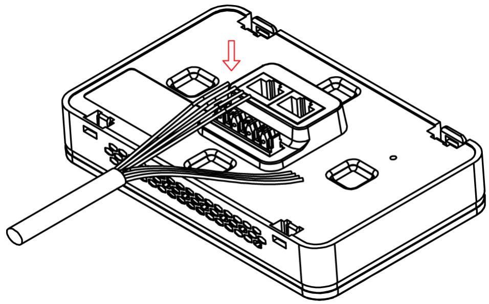
natural_image
Technical line drawing of an electronic device with exposed wiring and a cable (no text or symbols)5 Trim any excess wires. Place the dust caps over the terminated wires.
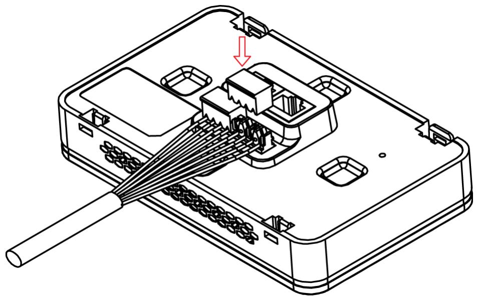
natural_image
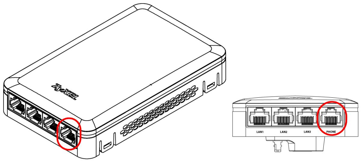
Technical line drawing of an electronic device with a cable inserted into a housing (no text or symbols)1.5.2 Phone Port
Connect a digital telephone to the RJ-45 PHONE port at the bottom of the NWA to forward voice traffic to/from the telephone switchboard that is connected to the RJ-45 PHONE port on the back of the NWA. The NWA does not support VoIP (Voice over Internet Protocol) and the PHONE port is NOT for making calls over the regular networking network (PSTN), either.
1.5.3 Console Port
To use the CLI commands to configure the NWA, connect an RJ-45-to-DB-9 cable to the PHONE port at the bottom of the NWA.
For local management, you can use a computer with terminal emulation software configured to the following parameters:
• VT100 terminal emulation
- 115200 bps
• No parity, 8 data bits, 1 stop bit
- No flow control
The following table shows you the wire color codes and pin assignment for the console cable.
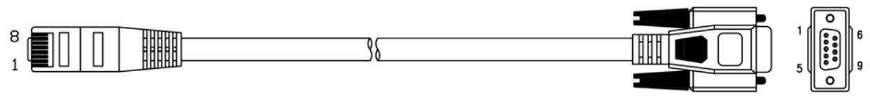
Table 5 RJ45-to-DB-9 Console Cable Color Codes
| RJ45 PIN# | WIRE COLOR | DB-9 PIN# |
| 1 | Black | 1 |
| 7 | Brown | 2 |
| 2 | Blue | 3 |
| 8 | Purple | 5 |
1.6 LEDs
The LEDs of your WAC6500 and NWA5301 can be controlled by using the Suppression feature such that the LEDs stay lit (ON) or OFF after the device is ready.
The WAC6500 also features Locator LED which allows you to see the actual location of the WAC6500 between several devices in the network.
Following are LED descriptions for the NWA/WAC series models.
1.6.1 WAC6502D-E, WAC6502D-S, and WAC6503D-S
The LEDs will stay ON when the WAC6500 Series is ready. You can change this setting in the Maintenance > LEDs > Suppression screen.
Figure 5 WAC6500 Series LEDs
The following table describes the LEDs.
Table 6 WAC6500 Series LEDs
| LED | COLOR | STATUS | DESCRIPTION |
| PWR/SYS | Red | Slow Blinking (On for 1s, Off for 1s) | The WAC is booting up. |
| Green | On | ||
| Red | Off | The WAC is ready for use. | |
| Green | On | ||
| Red | On | There is system error and the WAC cannot boot up, or the WAC suffered a system failure. | |
| Green | Off | ||
| Red | Fast Blinking (on for 50ms, Off for 50ms) | The WAC is doing firmware upgrade. | |
| Green | Off | ||
| Red | Slow Blinking (blink for 3 times, Off for 3s) | The Uplink port is disconnected. | |
| Green | Off | ||
| Red | Slow Blinking (blink for 2 times, Off for 3s) | The wireless module of the WAC is disabled or failed. | |
| Green | Off | ||
Management | Green | On | The WAC AP is managed by a controller. |
| Slow Blinking (blink for 3 times, Off for 3s) | The WAC AP is searching (discovery) for a controller. | ||
| Off | The WAC AP is in standalone mode. | ||
WLAN | Green | On | The 2.4 GHz WLAN is active. |
| Off | The 2.4 GHz WLAN is not active. | ||
WLAN | Green | On | The 5 GHz WLAN is active. |
| Off | The 5 GHz WLAN is not active. | ||
UPLINK | Amber/Green | On | Amber - The port is operating as a 100-Mbps connection.Green - The port is operating as a Gigabit connection (1000 Mbps). |
| Blinking | The WAC is sending/receiving data through the port. | ||
| Off | The port is not connected. | ||
LAN | Amber/Green | On | Amber - The port is operating as a 100-Mbps connection.Green - The port is operating as a Gigabit connection (1000 Mbps). |
| Blinking | The LAN port is sending/receiving data through the port. | ||
| Off | The LAN port is not connected. | ||
Locator | White | Blinking | The Locator is activated and will show the actual location of the WAC between several devices in the network. |
| Off | The Locator function is off. |
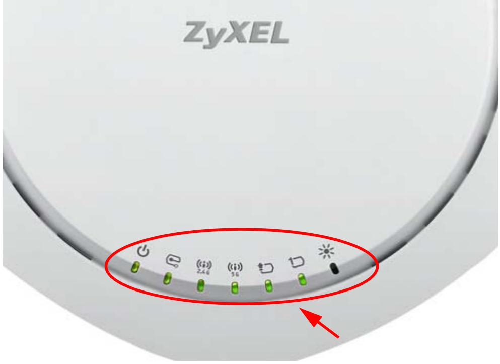
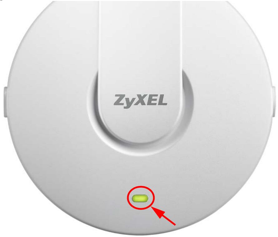
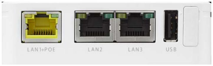
1.6.2 NWA1123-AC PRO and WAC6103D-I
The LEDs will stay ON when the NWA1123-AC PRO or WAC6103D-I is ready. You can change this setting in the Maintenance > LEDs > Suppression screen.
Figure 6 NWA1123-AC PRO and WAC6103D-I LEDs
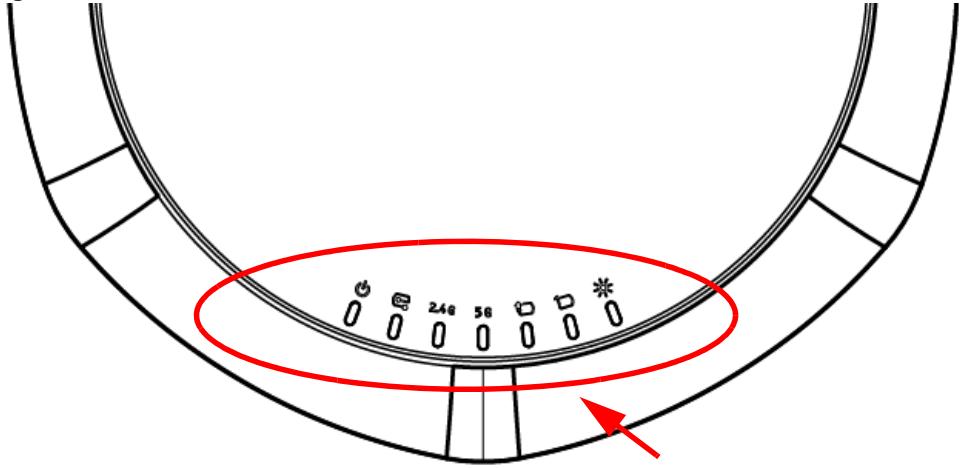
The following table describes the LEDs.
Table 7 NWA1123-AC PRO and WAC6103D-I LEDs
| LED | COLOR | STATUS | DESCRIPTION |
| PWR/SYS[ccxx] | Red | Slow Blinking (On for 1s, Off for 1s) | The NWA/WAC is booting up. |
| Green | On | ||
| Red | Off | The NWA/WAC is ready for use. | |
| Green | On | ||
| Red | On | There is system error and the NWA/WAC cannot boot up, or the NWA/WAC suffered a system failure. | |
| Green | Off | ||
| Red | Fast Blinking (on for 50ms, Off for 50ms) | The NWA/WAC is doing firmware upgrade. | |
| Green | Off | ||
| Red | Slow Blinking (blink for 3 times, Off for 3s) | The Uplink port is disconnected. | |
| Green | Off | ||
| Red | Slow Blinking (blink for 2 times, Off for 3s) | The wireless module of the NWA/WAC is disabled or failed. | |
| Green | Off | ||
| Management | Green | On | The NWA/WAC is managed by a controller. |
| Slow Blinking (blink for 3 times, Off for 3s) | The NWA/WAC is searching (discovery) for a controller. | ||
| Off | The NWA/WAC is in standalone mode. | ||
| WLAN24G | Green | On | The antenna switch is set to “Ceiling” for the radio.The 2.4 GHz WLAN is active. |
| Amber | On | The antenna switch is set to “Wall” for the radio.The 2.4 GHz WLAN is active. | |
| Off | The 2.4 GHz WLAN is not active. | ||
| WLAN5G | Green | On | The antenna switch is set to “Ceiling” for the radio.The 5 GHz WLAN is active. |
| Amber | On | The antenna switch is set to “Wall” for the radio.The 5 GHz WLAN is active. | |
| Off | The 5 GHz WLAN is not active. | ||
| UPLINK↑ | Amber/ Green | On | Amber - The port is operating as a 100-Mbps connection.Green - The port is operating as a Gigabit connection (1000 Mbps). |
| Blinking | The NWA/WAC is sending/receiving data through the port. | ||
| Off | The port is not connected. | ||
| LAN | Amber/ Green | On | Amber - The port is operating as a 100-Mbps connection.Green - The port is operating as a Gigabit connection (1000 Mbps). |
| Blinking | The LAN port is sending/receiving data through the port. | ||
| Off | The LAN port is not connected. | ||
| Locator | White | Blinking | The Locator is activated and will show the actual location of the NWA/WAC between several devices in the network. |
| Off | The Locator function is off. |
1.6.3 NWA5301-NJ
The LEDs automatically turn off when the NWA5301-NJ is ready. You can press the LED ON button for one second to turn on the LEDs again. The LEDs will blink and turn off after two minutes.
Figure 7 NWA5301-NJ LEDs
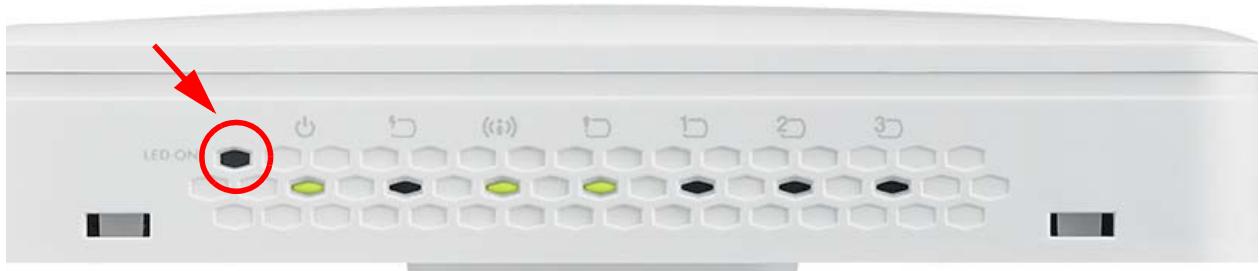
The following are the LED descriptions for your NWA5301-NJ.
Table 8 NWA5301-NJ LEDs
| LABEL | COLOR | STATUS | DESCRIPTION |
| PWR/SYS[2082] | Amber | Slow Blinking (On for 1s, Off for 1s) | The NWA is booting up. |
| Green | On | ||
| Amber | Off | The NWA is ready for use. | |
| Green | On | ||
| Amber | Slow Blinking (blink for 3 times, Off for 3s) | The NWA is discovering an AP controller | |
| Green | On | ||
| Amber | On | The NWA failed to boot up or is experiencing system failure. | |
| Green | Off | ||
| Amber | Fast Blinking (On for 50ms times, Off for 50ms) | The NWA is undergoing firmware upgrade. | |
| Green | Off | ||
| Amber | Slow Blinking (blink for 3 times, Off for 3s) | The Uplink port is disconnected. | |
| Green | Off | ||
| Amber | Slow Blinking (blink for 2 times, Off for 3s) | The wireless module of the WAC is disabled or failed. | |
| Green | Off | ||
PoE | Green | On | Power is supplied to the yellow PoE Ethernet port (LAN1). |
| Off | There is no power supply. | ||
WLAN | Green | On | The WLAN is active. |
| Off | The WLAN is not active. | ||
UPLINK | Green | On | The port is connected. |
| Blinking | The NWA is sending/receiving data through the port. | ||
| Off | The port is not connected. | ||
LAN1-3   | Green | On | The port is connected. |
| Blinking | The NWA is sending/receiving data through the port. | ||
| Off | The port is not connected. |
1.6.4 NWA1123-ACv2, NWA5121-N, NWA5121-NI, NWA5123-AC and NWA5123-NI
The following are the LED descriptions for your NWA1123/5120 series.
Figure 8 NWA1123/5120 Series LED
The following are the LED descriptions for your NWA1123/5120 series.
Table 9 NWA1123/5120 Series LED
| COLOR | STATUS | DESCRIPTION |
| Amber | Slow Blinking (On for 1s, Off for 1s) | The NWA is booting up. |
| Green | Off | |
| Amber | Off | The NWA is ready for use. |
| Green | Off | |
| Amber | Off | The NWA's wireless interface is activated. |
| Green | On | |
| Amber | Slow Blinking (blink for 3 times, Off for 3s) | The NWA is discovering an AP controller. |
| Green | On | |
| Amber | On | The NWA failed to boot up or is experience system failure. |
| Green | Off | |
| Amber | Fast Blinking (On for 50ms, Off for 50ms) | The NWA is undergoing firmware upgrade. |
| Green | Off | |
| Amber | Slow Blinking (blink for 3 times, Off for 3s) | The Uplink port is disconnected. |
| Green | Off | |
| Amber | Slow Blinking (blink for 2 times, Off for 3s) | The wireless LAN is disabled or fails. |
| Green | Off |
1.6.5 WAC5302D-S
The LEDs automatically turn off when the WAC5302D-S is ready. You can press the LED ON button for one second to turn on the LEDs again. The LEDs will blink and turn off after two minutes.
Figure 9 WAC5302D-S LEDs

The following table describes the LEDs.
Table 10 WAC5302D-S LEDs
| LED | COLOR | STATUS | DESCRIPTION |
PWR/SYS | Red | Slow Blinking (On for 1s, Off for 1s) | The WAC is booting up. |
| Green | On | ||
| Red | Off | The WAC is ready for use. | |
| Green | On | ||
| Red | On | There is system error and the WAC cannot boot up, or the WAC suffered a system failure. | |
| Green | Off | ||
| Red | Fast Blinking (on for 50ms, Off for 50ms) | The WAC is doing firmware upgrade. | |
| Green | Off | ||
| Red | Slow Blinking (blink for 3 times, Off for 3s) | The Uplink port is disconnected. | |
| Green | Off | ||
| Red | Slow Blinking (blink for 2 times, Off for 3s) | The wireless module of the WAC is disabled or failed. | |
| Green | Off | ||
Management | Green | On | The WAC AP is managed by a controller. |
| Slow Blinking (blink for 3 times, Off for 3s) | The WAC AP is searching (discovery) for a controller. | ||
| Off | The WAC AP is in standalone mode. | ||
UPLINK | Amber/Green | On | Amber - The port is operating as a 10/100-Mbps connection.Green - The port is operating as a Gigabit connection (1000 Mbps). |
| Blinking | The WAC is sending/receiving data through the port. | ||
| Off | The port is not connected. | ||
WLAN ---- ---- | Green | On | The 2.4 GHz WLAN is active. |
| Off | The 2.4 GHz WLAN is not active. | ||
WLAN | Green | On | The 5 GHz WLAN is active. |
| Off | The 5 GHz WLAN is not active. | ||
| LAN | Amber/Green | On | Amber - The port is operating as a 10/100-Mbps connection.Green - The port is operating as a Gigabit connection (1000 Mbps). |
| Blinking | The LAN port is sending/receiving data through the port. | ||
| Off | The LAN port is not connected. |
1.7 Starting and Stopping the NWA/WAC
Here are some of the ways to start and stop the NWA/WAC.
Always use Maintenance > Shutdown or the shutdown command before you turn off the NWA/WAC or remove the power. Not doing so can cause the firmware to become corrupt.
Table 11 Starting and Stopping the NWA/WAC
| METHOD | DESCRIPTION |
| Turning on the power | A cold start occurs when you turn on the power to the NWA/WAC. The NWA/WAC powers up, checks the hardware, and starts the system processes. |
| Rebooting the NWA/WAC | A warm start (without powering down and powering up again) occurs when you use the Reboot button in the Reboot screen or when you use the reboot command. The NWA/WAC writes all cached data to the local storage, stops the system processes, and then does a warm start. |
| Using the RESET button | If you press the RESET button on the back of the NWA/WAC, the NWA/WAC sets the configuration to its default values and then reboots. See Section 20.6 on page 197 for more information. |
| Clicking Maintenance > Shutdown > Shutdown or using the shutdown command | Clicking Maintenance > Shutdown > Shutdown or using the shutdown command writes all cached data to the local storage and stops the system processes. Wait for the device to shut down and then manually turn off or remove the power. It does not turn off the power. |
| Disconnecting the power | Power off occurs when you turn off the power to the NWA/WAC. The NWA/WAC simply turns off. It does not stop the system processes or write cached data to local storage. |
The NWA/WAC does not stop or start the system processes when you apply configuration files or run shell scripts although you may temporarily lose access to network resources.
CHAPTER 2
The Web Configurator
2.1 Overview
The NWA/WAC Web Configurator allows easy management using an Internet browser. Browsers supported are:
- Firefox 36.0.1 or later
- Chrome 41.0 or later
- IE 10 or later
The recommended screen resolution is 1024 x 768 pixels and higher.
2.2 Accessing the Web Configurator
1 Make sure your NWA/WAC is working in standalone AP mode (see Section 1.1.1 on page 13) and hardware is properly connected. See the Quick Start Guide.
2 If the NWA/WAC and your computer are not connected to a DHCP server, make sure your computer's IP address is in the range between "192.168.1.3" and "192.168.1.254".
3 Browse to the NWA/WAC's DHCP-assigned IP address or http://192.168.1.2. The Login screen appears.
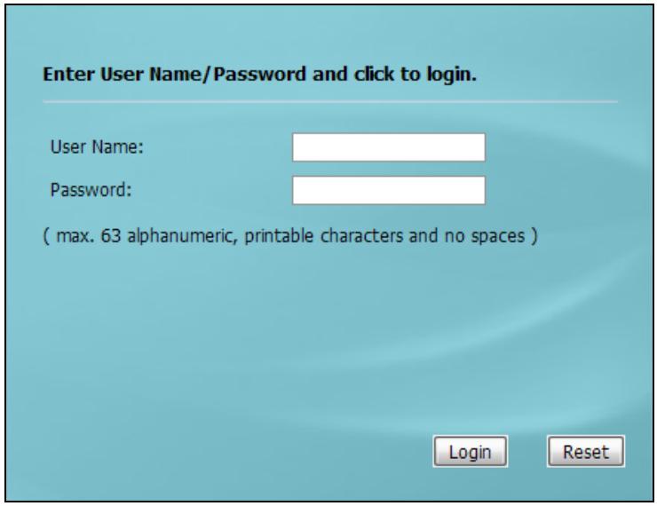
4 Enter the user name (default: "admin") and password (default: "1234").
5 Click Login. If you logged in using the default user name and password, the Update Admin Info screen appears. Otherwise, the dashboard appears.
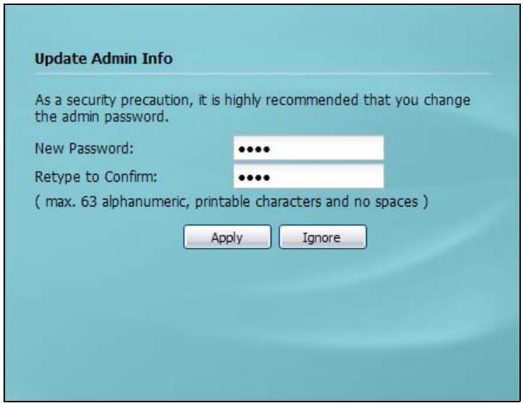
The Update Admin Info screen appears every time you log in using the default user name and default password. If you change the password for the default user account, this screen does not appear anymore.
2.3 Navigating the Web Configurator
The following summarizes how to navigate the web configurator from the Dashboard screen. This guide uses the NWA1123-AC PRO screens as an example. The screens may vary slightly for different models.
Figure 10 The Web Configurator's Main Screen
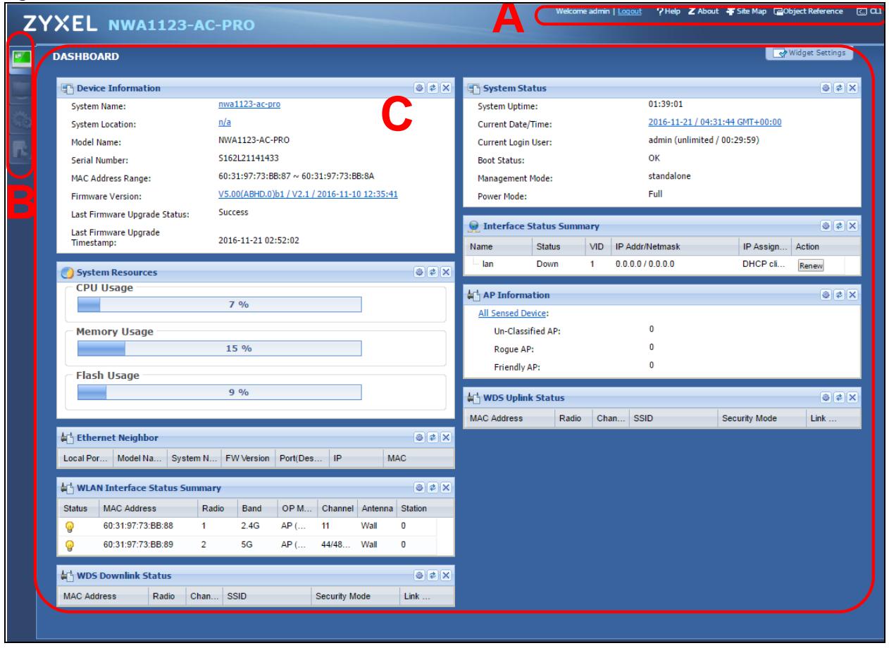
The Web Configurator's main screen is divided into these parts:
• A - Title Bar
• B - Navigation Panel
- C - Main Window
2.3.1 Title Bar
The title bar provides some useful links that always appear over the screens below, regardless of how deep into the Web Configurator you navigate.
Figure 11 Title Bar

The icons provide the following functions.
Table 12 Title Bar: Web Configurator Icons
| LABEL | DESCRIPTION |
| Logout | Click this to log out of the Web Configurator. |
| Help | Click this to open the help page for the current screen. |
| About | Click this to display basic information about the NWA/WAC. |
| Site Map | Click this to see an overview of links to the Web Configurator screens. |
| Object Reference | Click this to open a screen where you can check which configuration items reference an object. |
| CLI | Click this to open a popup window that displays the CLI commands sent by the Web Configurator. |
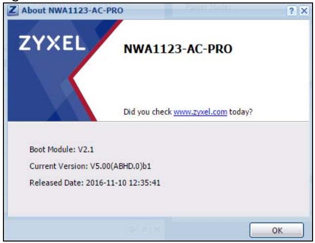
About
Click About to display basic information about the NWA/WAC.
Figure 12 About
The following table describes labels that can appear in this screen.
Table 13 About
| LABEL | DESCRIPTION |
| Boot Module | This shows the version number of the software that handles the booting process of the NWA/WAC. |
| Current Version | This shows the firmware version of the NWA/WAC. |
| Released Date | This shows the date (yyyy-mm-dd) and time (hh:mm:ss) when the firmware is released. |
| OK | Click this to close the screen. |
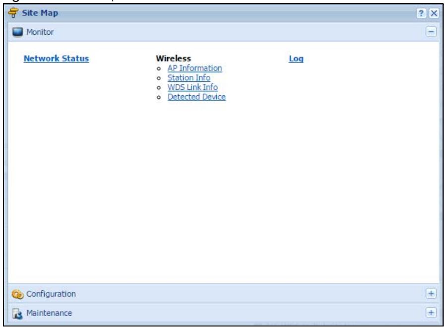
Site Map
Click Site MAP to see an overview of links to the Web Configurator screens. Click a screen's link to go to that screen.
Figure 13 Site Map
Object Reference
Click Object Reference to open the Object Reference screen. Select the type of object and the individual object and click Refresh to show which configuration settings reference the object.
Figure 14 Object Reference
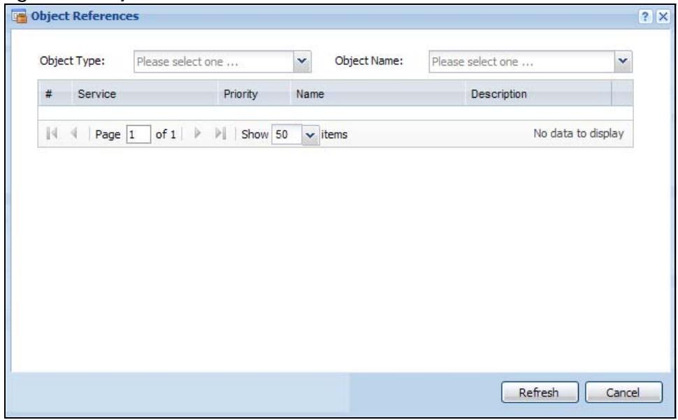
The fields vary with the type of object. The following table describes labels that can appear in this screen.
Table 14 Object References
| LABEL | DESCRIPTION |
| Object Name | This identifies the object for which the configuration settings that use it are displayed. Click the object's name to display the object's configuration screen in the main window. |
| # | This field is a sequential value, and it is not associated with any entry. |
| Service | This is the type of setting that references the selected object. Click a service's name to display the service's configuration screen in the main window. |
| Priority | If it is applicable, this field lists the referencing configuration item's position in its list, otherwise N/A displays. |
| Name | This field identifies the configuration item that references the object. |
| Description | If the referencing configuration item has a description configured, it displays here. |
| Refresh | Click this to update the information in this screen. |
| Cancel | Click Cancel to close the screen. |
CLI Messages
Click CLI to look at the CLI commands sent by the Web Configurator. These commands appear in a popup window, such as the following.
Figure 15 CLI Messages
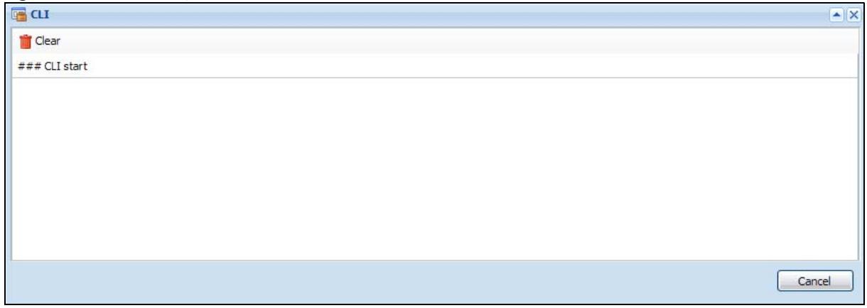
Click Clear to remove the currently displayed information.
Note: See the Command Reference Guide for information about the commands.
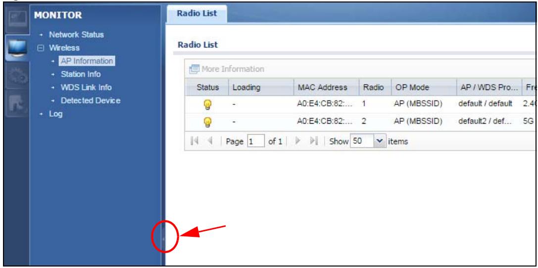
2.3.2 Navigation Panel
Use the menu items on the navigation panel to open screens to configure NWA/WAC features. Click the arrow in the middle of the right edge of the navigation panel to hide the navigation panel menus or drag it to resize them. The following sections introduce the NWA/WAC's navigation panel menus and their screens.
Figure 16 Navigation Panel
Dashboard
The dashboard displays general device information, system status, system resource usage, and interface status in widgets that you can re-arrange to suit your needs.
For details on the Dashboard's features, see Chapter 3 on page 42.
Monitor Menu
The monitor menu screens display status and statistics information.
Table 15 Monitor Menu Screens Summary
| FOLDER OR LINK | TAB | FUNCTION |
| Network Status | Network Status | Display general LAN interface information and packet statistics. |
| Wireless | ||
| AP Information | Radio List | Display information about the radios of the connected APs. |
| Station Info | Station List | Display information about the connected stations. |
| WDS Link Info | WDS Link Info | Display statistics about the NWA/WAC's WDS (Wireless Distribution System) connections. |
| Detected Device | Detected Device | Display information about suspected rogue APs. |
| Log | View Log | Display log entries for the NWA/WAC. |
Configuration Menu
Use the configuration menu screens to configure the NWA/WAC's features.
Table 16 Configuration Menu Screens Summary
| FOLDER OR LINK | TAB | FUNCTION |
| Network | IP Setting | Configure the IP address for the NWA/WAC Ethernet interface. |
| VLAN | Manage the Ethernet interface VLAN settings. | |
| AC Discovery | Configures the NWA/WAC's AP Controller settings. | |
| Wireless | ||
| AP Management | WLAN Setting | Manage the NWA/WAC's general wireless settings. |
| MON Mode | Rogue/Friendly AP List | Configure how the NWA/WAC monitors for rogue APs. |
| Load Balancing | Load Balancing | Configure load balancing for traffic moving to and from wireless clients. |
| DCS | DCS | Configure dynamic wireless channel selection. |
| Object | ||
| User | User | Create and manage users. |
| Setting | Manage default settings for all users, general settings for user sessions, and rules to force user authentication. | |
| AP Profile | Radio | Create and manage wireless radio settings files that can be associated with different APs. |
| SSID | Create and manage wireless SSID, security, MAC filtering, and layer-2 isolation files that can be associated with different APs. | |
| MON Profile | MON Profile | Create and manage rogue AP monitoring files that can be associated with different APs. |
| WDS Profile | WDS | Create and manage WDS profiles that can be used to connect to different APs in WDS. |
| Certificate | My Certificates | Create and manage th e NWA/WAC's certificates. |
| Trusted Certificates | Import and manage certificates from trusted sources. | |
| System | ||
| Host Name | Host Name | Configure the system and domain name for the NWA/WAC. |
| Date/Time | Date/Time | Configure the current date, time, and time zone in the NWA/WAC. |
| WWW | Service Control | Configure HTTP, HTTPS, and general authentication. |
| SSH | SSH | Configure SSH server and SSH service settings. |
| TELNET | TELNET | Configure telnet server settings for the NWA/WAC. |
| FTP | FTP | Configure FTP server settings. |
| SNMP | SNMP | Configure SNMP communities and services. |
| Log & Report | ||
| Email Daily Report | Email Daily Report | Configure where and how to send daily reports and what reports to send. |
| Log Setting | Log Setting | Configure the system log, e-mail logs, and remote syslog servers. |
Maintenance Menu
Use the maintenance menu screens to manage configuration and firmware files, run diagnostics, and reboot or shut down the NWA/WAC.
Table 17 Maintenance Menu Screens Summary
| FOLDER OR LINK | TAB | FUNCTION |
| File Manager | Configuration File | Manage and upload configuration files for the NWA/WAC. |
| Firmware Package | View the current firmware version and to upload firmware. | |
| Shell Script | Manage and run shell script files for the NWA/WAC. | |
| Diagnostics | Diagnostics | Collect diagnostic information. |
| LEDs | Suppression | Enable this feature to keep the LEDs off after the NWA/WAC starts. |
| Locator | Enable this feature to see the actual location of the NWA/WAC between several devices in the network. | |
| Antenna | Antenna Switch | Change antenna orientation for the radios. |
| Reboot | Reboot | Restart the NWA/WAC. |
| Shutdown | Shutdown | Turn off the NWA/WAC. |
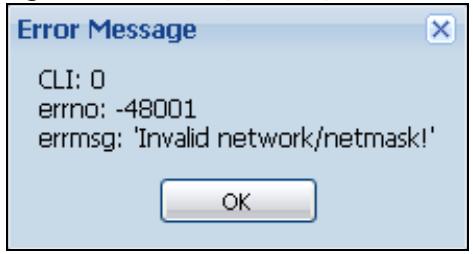
2.3.3 Warning Messages
Warning messages, such as those resulting from misconfiguration, display in a pop up window.
Figure 17 Warning Message
2.3.4 Tables and Lists
The Web Configurator tables and lists are quite flexible and provide several options for how to display their entries.
2.3.4.1 Manipulating Table Display
Here are some of the ways you can manipulate the Web Configurator tables.
1 Click a column heading to sort the table's entries according to that column's criteria.
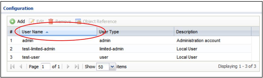
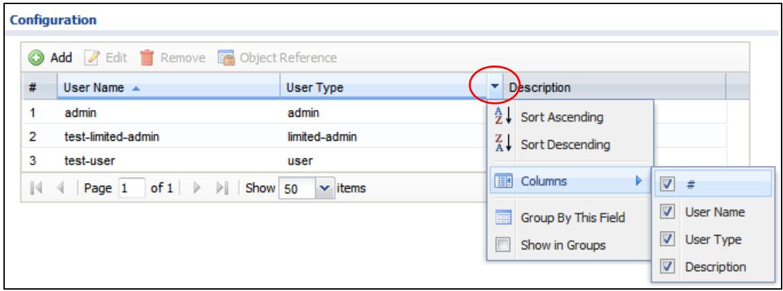
2 Click the down arrow next to a column heading for more options about how to display the entries. The options available vary depending on the type of fields in the column. Here are some examples of what you can do:
- Sort in ascending alphabetical order
- Sort in descending (reverse) alphabetical order
- Select which columns to display
- Group entries by field
• Show entries in groups
- Filter by mathematical operators (<, >, or =) or searching for text.
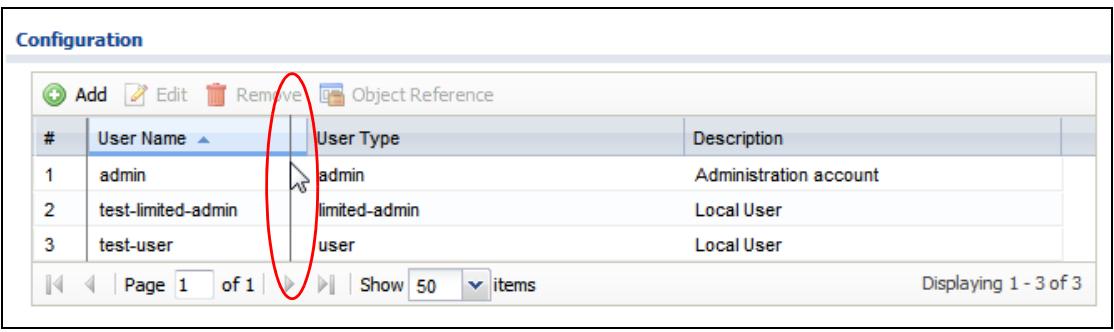
3 Select a column heading cell's right border and drag to re-size the column.
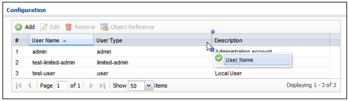
4 Select a column heading and drag and drop it to change the column order. A green check mark displays next to the column's title when you drag the column to a valid new location.
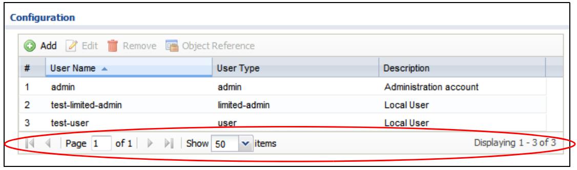
5 Use the icons and fields at the bottom of the table to navigate to different pages of entries and control how many entries display at a time.
2.3.4.2 Working with Table Entries
The tables have icons for working with table entries. A sample is shown next. You can often use the [Shift] or [Ctrl] key to select multiple entries to remove, activate, or deactivate.
Table 18 Common Table Icons
| Radio Summary | ||||
| # | Status | Profile Name ▲ | Frequency Band | Channel ID |
| 1 | default | 2.4G | 6 | |
| 2 | default2 | 5G | 36 | |
Here are descriptions for the most common table icons.
Table 19 Common Table Icons
| LABEL | DESCRIPTION |
| Add | Click this to create a new entry. For features where the entry's position in the numbered list is important (features where the NWA/WAC applies the table's entries in order like the firewall for example), you can select an entry and click Add to create a new entry after the selected entry. |
| Edit | Double-click an entry or select it and click Edit to open a screen where you can modify the entry's settings. In some tables you can just click a table entry and edit it directly in the table. For those types of tables small red triangles display for table entries with changes that you have not yet applied. |
| Remove | To remove an entry, select it and click Remove. The NWA/WAC confirms you want to remove it before doing so. |
| Activate | To turn on an entry, select it and click Activate. |
| Inactivate | To turn off an entry, select it and click Inactivate. |
| Object Reference | Select an entry and click Object Reference to open a screen that shows which settings use the entry. |
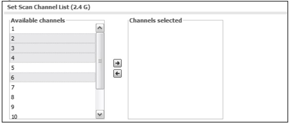
2.3.4.3 Working with Lists
When a list of available entries displays next to a list of selected entries, you can often just double-click an entry to move it from one list to the other. In some lists you can also use the [Shift] or [Ctrl] key to select multiple entries, and then use the arrow button to move them to the other list.
Figure 18 Working with Lists
PART II
Technical Reference
CHAPTER 3 Dashboard
3.1 Overview
Use the Dashboard screens to check status information about the NWA/WAC.
3.1.1 What You Can Do in this Chapter
- The main Dashboard screen (Section 3.2 on page 42) displays the NWA/WAC's general device information, system status, system resource usage, and interface status. You can also display other status screens for more information.
3.2 Dashboard
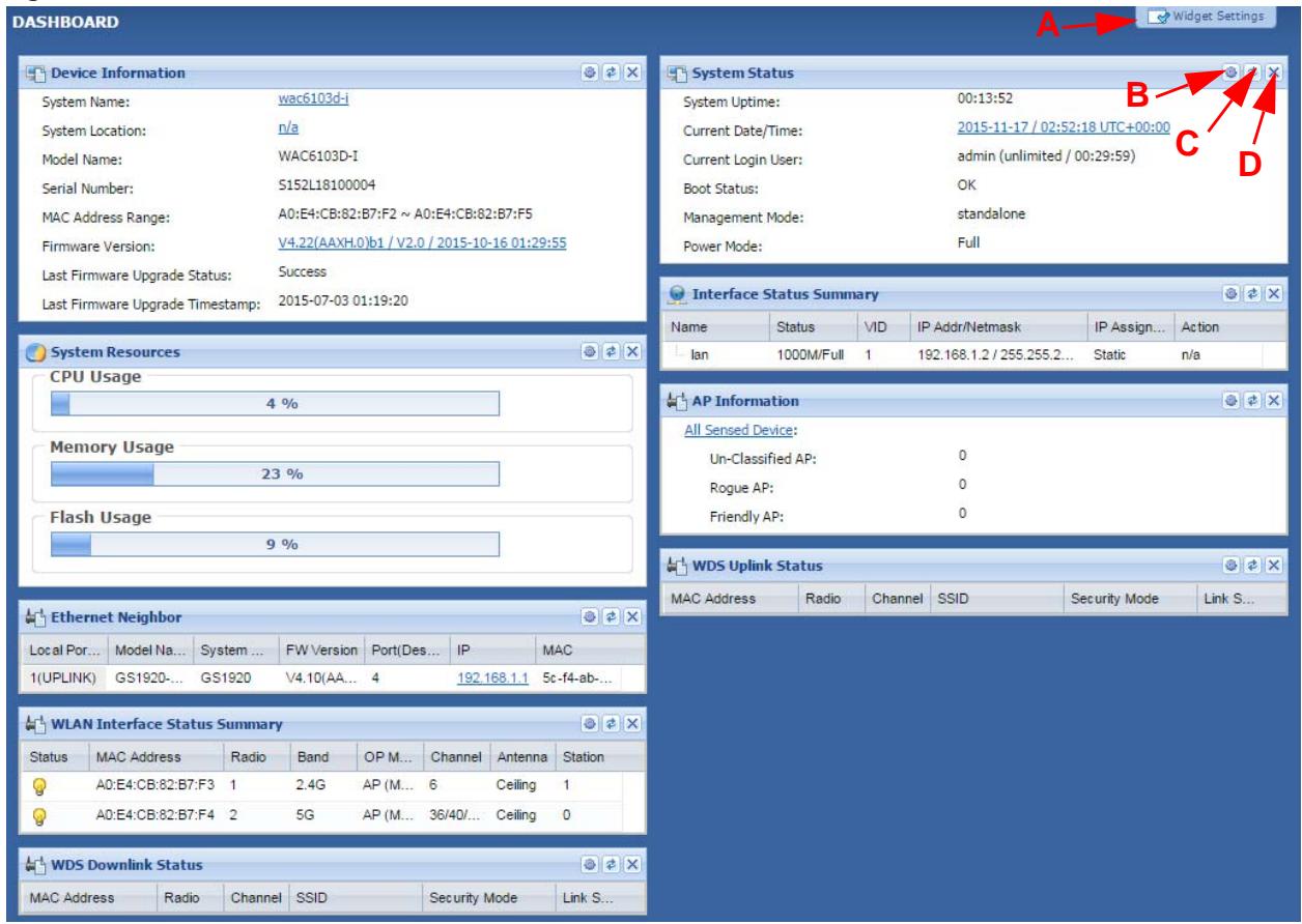
This screen is the first thing you see when you log into the NWA/WAC. It also appears every time you click the Dashboard icon in the navigation panel. The Dashboard displays general device information, system status, system resource usage, and interface status in widgets that you can re-arrange to suit your needs. You can also collapse, refresh, and close individual widgets.
Figure 19 Dashboard
The following table describes the labels in this screen.
Table 20 Dashboard
| LABEL | DESCRIPTION |
| Widget Settings (A) | Use this link to re-open closed widgets. Widgets that are already open appear grayed out. |
| Refresh Time Setting (B) | Set the interval for refreshing the information displayed in the widget. |
| Refresh Now (C) | Click this to update the widget's information immediately. |
| Close Widget (D) | Click this to close the widget. UseWidget Settingto re-open it. |
| Device Information | |
| System Name | This field displays the name used to identify the NWA/WAC on any network. Click the icon to open the screen where you can change it. |
| System Location | This field displays the location of the NWA/WAC. Click the icon to open the screen where you can change it. |
| Model Name | This field displays the model name of this NWA/WAC. |
| Serial Number | This field displays the serial number of this NWA/WAC. |
| MAC Address Range | This field displays the MAC addresses used by the NWA/WAC. Each physical port or wireless radio has one MAC address. The first MAC address is assigned to the Ethernet LAN port, the second MAC address is assigned to the first radio, and so on. |
| Firmware Version | This field displays the version number and date of the firmware the NWA/WAC is currently running. Click the icon to open the screen where you can upload firmware. |
| Last Firmware Upgrade Status | This field displays whether the latest firmware update was successfully completed. |
| Last Firmware Upgrade Timestamp | This field displays the date and time when the last firmware update was made. |
| System Resources | |
| CPU Usage | This field displays what percentage of the NWA/WAC's processing capability is currently being used. Hover your cursor over this field to display the Show CPU Usage icon that takes you to a chart of the NWA/WAC's recent CPU usage. |
| Memory Usage | This field displays what percentage of the NWA/WAC's RAM is currently being used. Hover your cursor over this field to display the Show Memory Usage icon that takes you to a chart of the NWA/WAC's recent memory usage. |
| Flash Usage | This field displays what percentage of the NWA/WAC's onboard flash memory is currently being used. |
| Ethernet Neighbor | |
| Local Port (Description) | This field displays the port of the NWA/WAC, on which the neighboring device is discovered. |
| Model Name | This field displays the model name of the discovered device. |
| System Name | This field displays the system name of the discovered device. |
| FW Version | This field displays the firmware version of the discovered device. |
| Port (Description) | This field displays the discovered device's port which is connected to the NWA/WAC. |
| IP | This field displays the IP address of the discovered device. Click the IP address to access and manage the discovered device using its web configurator. |
| MAC | This field displays the MAC address of the discovered device. |
| WDS (Wireless Distribution System) Uplink/Downlink Status | |
| MAC Address | This field displays the MAC address of the root AP or repeater to which the NWA/WAC is connected using WDS. |
| Radio | This field displays the radio number on the root AP or repeater to which the NWA/WAC is connected using WDS. |
| Channel | This field displays the channel number on the root AP or repeater to which the NWA/WAC is connected using WDS. |
| SSID | This field displays the name of the wireless network to which the NWA/WAC is connected using WDS. |
| Security Mode | This field displays which secure encryption methods is being used by the NWA/WAC to connect to the root AP or repeater using WDS. |
| Link Status | This field displays the RSSI (Received Signal Strength Indicator) and transmission/reception rate of the wireless connection in WDS. |
| System Status | |
| System Uptime | This field displays how long the NWA/WAC has been running since it last restarted or was turned on. |
| Current Date/ Time | This field displays the current date and time in the NWA/WAC. The format is yyyy-mm-dd hh:mm:ss. |
| Current Login User | This field displays the user name used to log in to the current session, the amount of reauthentication time remaining, and the amount of lease time remaining. |
| Boot Status | This field displays details about the NWA/WAC's startup state.OK - The NWA/WAC started up successfully.Firmware update OK - A firmware update was successful.Problematic configuration after firmware update - The application of the configuration failed after a firmware upgrade.System default configuration - The NWA/WAC successfully applied the system default configuration. This occurs when the NWA/WAC starts for the first time or you intentionally reset the NWA/WAC to the system default settings.Fallback to lastgood configuration - The NWA/WAC was unable to apply the startup-config.conf configuration file and fell back to the lastgood.conf configuration file.Fallback to system default configuration - The NWA/WAC was unable to apply the lastgood.conf configuration file and fell back to the system default configuration file (system-default.conf).Booting in progress - The NWA/WAC is still applying the system configuration. |
| Management Mode | This shows whether the NWA/WAC is set to work as a stand alone AP. |
| Power Mode | This displays the NWA/WAC's power status.Full - the NWA/WAC receives power using a power adaptor and/or through a PoE switch/injector using IEEE 802.3at PoE plus.Limited - the NWA/WAC receives power through a PoE switch/injector using IEEE 802.3af PoE even when it is also connected to a power source using a power adaptor.When the NWA/WAC is in limited power mode, the NWA/WAC throughput decreases and has just one transmitting radio chain.It always shows Full if the NWA/WAC does not support power detection. At the time of writing, only the WAC6500 series APs support the power detection feature. |
| Interface Status Summary | If an Ethernet interface does not have any physical ports associated with it, its entry is displayed in light gray text. Click the Detail icon to go to a (more detailed) summary screen of interface statistics. |
| Name | This field displays the name of each interface. |
| Status | This field displays the current status of each interface. The possible values depend on what type of interface it is.Inactive - The Ethernet interface is disabled.Down - The Ethernet interface is enabled but not connected.Speed / Duplex - The Ethernet interface is enabled and connected. This field displays the port speed and duplex setting (Full or Half). |
| VID | This field displays the VLAN ID to which the interface belongs. |
| IP Addr/Netmask | This field displays the current IP address and subnet mask assigned to the interface. If the IP address is 0.0.0.0, the interface is disabled or did not receive an IP address and subnet mask via DHCP. |
| IP Assignment | This field displays how the interface gets its IP address.Static - This interface has a static IP address.DHCP Client - This interface gets its IP address from a DHCP server. |
| Action | If the interface has a static IP address, this shows n/a.If the interface has a dynamic IP address, use this field to get or to update the IP address for the interface. Click Renew to send a new DHCP request to a DHCP server. |
| WLAN Interface Status Summary | This displays status information for the WLAN interface. |
| Status | This displays whether or not the WLAN interface is activated. |
| MAC Address | This displays the MAC address of the radio. |
| Radio | This indicates the radio number on the NWA/WAC. |
| Band | This indicates the wireless frequency band currently being used by the radio.This shows - when the radio is in monitor mode. |
| OP Mode | This indicates the radio's operating mode. Operating modes are AP (MBSSID), MON (monitor), Root AP or Repeater. |
| Channel | This indicates the channel number the radio is using. |
| Antenna | This indicates the antenna orientation for the radio (Wall or Ceiling).This field is not available if the NWA/WAC does not allow you to adjust antenna orientation for each radio using the web configurator or a physical switch. Refer to Table 1 on page 11 and Table 2 on page 12 to see if your NWA/WAC has an antenna switch. |
| Station | This displays the number of wireless clients connected to the NWA/WAC. |
| AP Information | This shows a summary of connected wireless Access Points (APs). |
| All Sensed Device | This sections displays a summary of all wireless devices detected by the network. Click the link to go to the Monitor > Wireless > Detected Device screen. |
| Un-Classified AP | This displays the number of detected unclassified APs. |
| Rogue AP | This displays the number of detected rogue APs. |
| Friendly AP | This displays the number of detected friendly APs. |
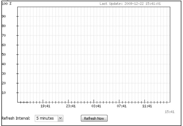
3.2.1 CPU Usage
Use this screen to look at a chart of the NWA/WAC's recent CPU usage. To access this screen, click CPU Usage in the dashboard.
Figure 20 Dashboard > CPU Usage
The following table describes the labels in this screen.
Table 21 Dashboard > CPU Usage
| LABEL | DESCRIPTION |
| % | The y-axis represents the percentage of CPU usage. |
| time | The x-axis shows the time period over which the CPU usage occurred |
| Refresh Interval | Enter how often you want this window to be automatically updated. |
| Refresh Now | Click this to update the information in the window right away. |
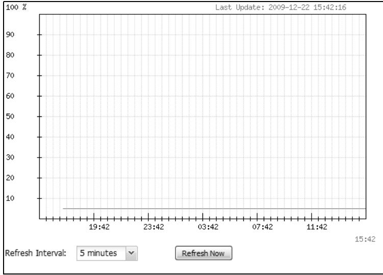
3.2.2 Memory Usage
Use this screen to look at a chart of the NWA/WAC's recent memory (RAM) usage. To access this screen, click Memory Usage in the dashboard.
Figure 21 Dashboard > Memory Usage
line
| Time | Value | | -------- | ----- | | 19:42 | 5 | | 23:42 | 5 | | 03:42 | 5 | | 07:42 | 5 | | 11:42 | 5 | | 15:42 | 5 |The following table describes the labels in this screen.
Table 22 Dashboard > Memory Usage
| LABEL | DESCRIPTION |
| The y-axis represents the percentage of RAM usage. | |
| The x-axis shows the time period over which the RAM usage occurred | |
| Refresh Interval | Enter how often you want this window to be automatically updated. |
| Refresh Now | Click this to update the information in the window right away. |
CHAPTER 4 Monitor
4.1 Overview
Use the Monitor screens to check status and statistics information.
4.1.1 What You Can Do in this Chapter
- The Network Status screen (Section 4.3 on page 49) displays general LAN interface information and packet statistics.
- The AP Information > Radio List screen (Section 4.4 on page 50) displays statistics about the wireless radio transmitters in the NWA/WAC.
- The Station Info screen (Section 4.5 on page 53) displays statistics pertaining to the associated stations.
- The WDS Link Info screen (Section 4.6 on page 54) displays statistics about the NWA/WAC's WDS (Wireless Distribution System) connections.
- The Detected Device screen (Section 4.7 on page 55) displays information about suspected rogue APs.
- The View Log screen (Section 4.8 on page 56) displays the NWA/WAC's current log messages. You can change the way the log is displayed, you can e-mail the log, and you can also clear the log in this screen.
4.2 What You Need to Know
The following terms and concepts may help as you read through the chapter.
Rogue AP
Rogue APs are wireless access points operating in a network's coverage area that are not under the control of the network's administrators, and can open up holes in a network's security. See Chapter 9 on page 108 for details.
Friendly AP
Friendly APs are other wireless access points that are detected in your network, as well as any others that you know are not a threat (those from neighboring networks, for example). See Chapter 9 on page 108 for details.
4.3 Network Status
Use this screen to look at general Ethernet interface information and packet statistics. To access this screen, click Monitor > Network Status.
Figure 22 Monitor > Network Status
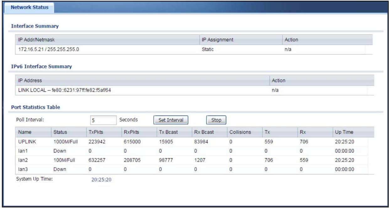
The following table describes the labels in this screen.
Table 23 Monitor > Network Status
| LABEL | DESCRIPTION |
| Interface SummaryIPv6 Interface Summary | Use the Interface Summary section for IPv4 network settings. Use the IPv6 Interface Summary section for IPv6 network settings if you connect your NWA/WAC to an IPv6 network. Both sections have similar fields as described below. |
| IP Addr/NetmaskIP Address | This field displays the current IP address (and subnet mask) of the interface. If the IP address is 0.0.0.0 (in the IPv4 network) or :: (in the IPv6 network), the interface does not have an IP address yet. |
| IP Assignment | This field displays how the interface gets its IPv4 address.Static - This interface has a static IPv4 address.DHCP Client - This interface gets its IPv4 address from a DHCP server. |
| Action | Use this field to get or to update the IP address for the interface. Click Renew to send a new DHCP request to a DHCP server. If the interface cannot use one of these ways to get or to update its IP address, this field displays n/a. |
| Port Statistics Table | |
| Poll Interval | Enter how often you want this window to be updated automatically, and click Set Interval. |
| Set Interval | Click this to set the Poll Interval the screen uses. |
| Stop | Click this to stop the window from updating automatically. You can start it again by setting the Poll Interval and clicking Set Interval. |
| Name | This field displays the name of the interface. |
| Status | This field displays the current status of the physical port. Down - The physical port is not connected. Speed / Duplex - The physical port is connected. This field displays the port speed and duplex setting (Full or Half). |
| TxPkts | This field displays the number of packets transmitted from the NWA/WAC on the physical port since it was last connected. |
| RxPkts | This field displays the number of packets received by the NWA/WAC on the physical port since it was last connected. |
| Tx Bcast | This field displays the number of broadcast packets transmitted from the NWA/WAC on the physical port since it was last connected. |
| Rx Bcast | This field displays the number of broadcast packets received by the NWA/WAC on the physical port since it was last connected. |
| Collisions | This field displays the number of collisions on the physical port since it was last connected. |
| Tx | This field displays the transmission speed, in bytes per second, on the physical port in the one-second interval before the screen updated. |
| Rx | This field displays the reception speed, in bytes per second, on the physical port in the one-second interval before the screen updated. |
| Up Time | This field displays how long the physical port has been connected. |
| System Up Time | This field displays how long the NWA/WAC has been running since it last restarted or was turned on. |
4.4 Radio List
Use this screen to view statistics for the NWA/WAC's wireless radio transmitters. To access this screen, click Monitor > Wireless > AP Information > Radio List.
Figure 23 Monitor > Wireless > AP Information > Radio List
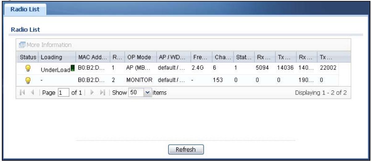
The following table describes the labels in this screen.
Table 24 Monitor > Wireless > AP Information > Radio List
| LABEL | DESCRIPTION |
| More Information | Click this to view additional information about the selected radio's wireless traffic and station count. Information spans a 24 hour period. |
| Status | This displays whether or not the radio is enabled. |
| Loading | This indicates the AP's load balance status (UnderLoad or OverLoad) when load balancing is enabled on the NWA/WAC. Otherwise, it shows - when load balancing is disabled or the radio is in monitor mode. |
| MAC Address | This displays the MAC address of the radio. |
| Radio | This indicates the radio number on the NWA/WAC to which it belongs. |
| OP Mode | This indicates the radio's operating mode. Operating modes are AP (MBSSID), MONITOR, Root AP or Repeater |
| AP/WDS Profile | This indicates the AP profile name and WDS profile name to which the radio belongs. |
| Profile | This indicates the AP profile name to which the radio belongs.This field is available only on the NWA/WAC that doesn't support WDS. |
| Frequency Band | This indicates the wireless frequency band currently being used by the radio.This shows - when the radio is in monitor mode. |
| Channel | This indicates the radio's channel ID. |
| Tx Power | This displays the output power of the radio. |
| Station | This displays the number of wireless clients connected to this radio on the NWA/WAC. |
| Rx PKT | This displays the total number of packets received by the radio. |
| Tx PKT | This displays the total number of packets transmitted by the radio. |
| Rx FCS Error Count | This indicates the number of received packet errors accrued by the radio. |
| Tx Retry Count | This indicates the number of times the radio has attempted to re-transmit packets. |
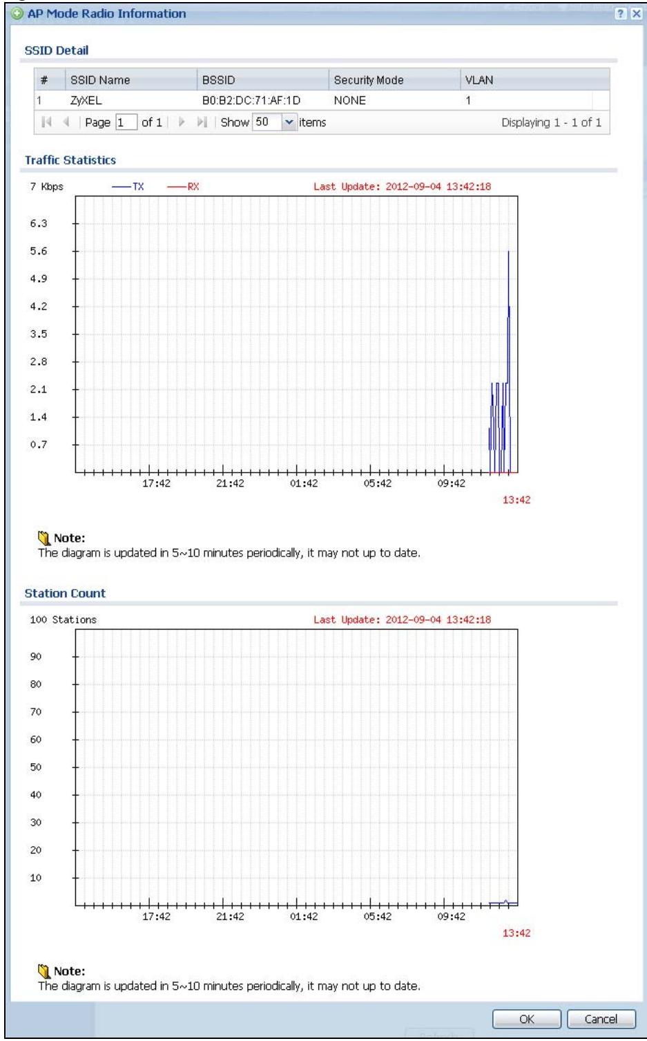
4.4.1 AP Mode Radio Information
This screen allows you to view a selected radio's SSID details, wireless traffic statistics and station count for the preceding 24 hours. To access this window, select a radio and click the More Information button in the Radio List screen.
Figure 24 Monitor > Wireless > AP Information > Radio List > More Information
line
| Time | RSSID (Kbps) | | -------- | ------------ | | 13:42 | 5.6 |The following table describes the labels in this screen.
Table 25 Monitor > Wireless > AP Information > Radio List > More Information
| LABEL | DESCRIPTION |
| SSID Detail | This list shows information about all the wireless clients that have connected to the specified radio over the preceding 24 hours. |
| # | This is the items sequential number in the list. It has no bearing on the actual data in this list. |
| SSID Name | This displays an SSID associated with this radio. There can be up to eight maximum. |
| BSSID | This displays a BSSID associated with this radio. The BSSID is tied to the SSID. |
| Security Mode | This displays the security mode in which the SSID is operating. |
| VLAN | This displays the VLAN ID associated with the SSID. |
| Traffic Statistics | This graph displays the overall traffic information of the radio over the preceding 24 hours. |
| This y-axis represents the amount of data moved across this radio in megabytes per second. | |
| This x-axis represents the amount of time over which the data moved across this radio. | |
| Station Count | This graph displays the connected station information of the radio over the preceding 24 hours |
| The y-axis represents the number of connected stations. | |
| The x-axis shows the time period over which a station was connected. | |
| Last Update | This field displays the date and time the information in the window was last updated. |
| OK | Click this to close this window. |
| Cancel | Click this to close this window. |
4.5 Station List
Use this screen to view statistics pertaining to the associated stations (or “wireless clients”). Click Monitor > Wireless > Station Info to access this screen.
Figure 25 Monitor > Wireless > Station Info
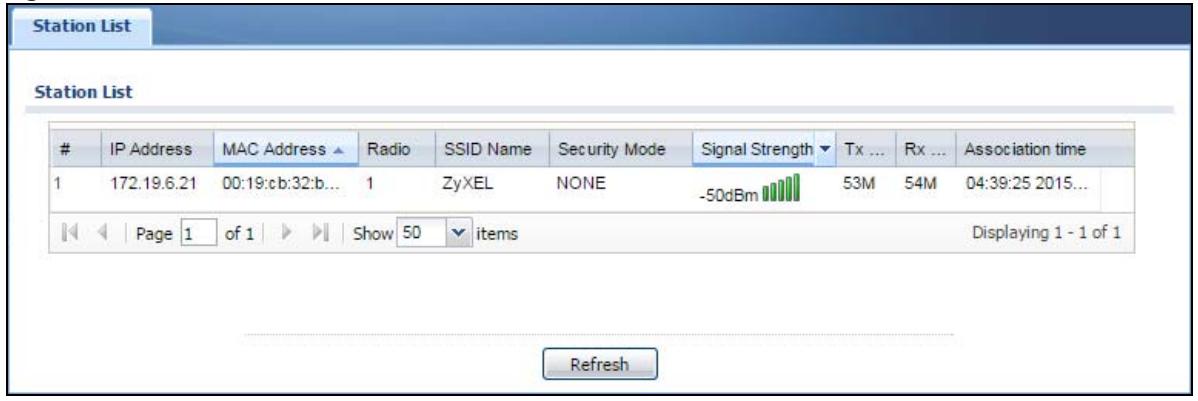
The following table describes the labels in this screen.
Table 26 Monitor > Wireless > Station Info
| LABEL | DESCRIPTION |
| # | This is the station's index number in this list. |
| IP Addresss | This is the station's IP address. |
| MAC Address | This is the station's MAC address. |
| Radio | This is the radio number on the NWA/WAC to which the station is connected. |
| SSID Name | This indicates the name of the wireless network to which the station is connected. A single AP can have multiple SSIDs or networks. |
| Security Mode | This indicates which secure encryption methods is being used by the station to connect to the network. |
| Signal Strength | This is the RSSI (Received Signal Strength Indicator) of the station's wireless connection. |
| Tx Rate | This is the maximum transmission rate of the station. |
| Rx Rate | This is the maximum reception rate of the station. |
| Association Time | This displays the time the station first associated with the NWA/WAC's wireless network. |
| Refresh | Click this to refresh the items displayed on this page. |
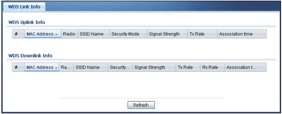
4.6 WDS Link Info
Use this screen to view the WDS traffic statistics between the NWA/WAC and a root AP or repeaters. Click Monitor > Wireless > WDS Link Info to access this screen.
Figure 26 Monitor > Wireless > WDS Link Info
The following table describes the labels in this screen.
Table 27 Monitor > Wireless > WDS Link Info
| LABEL | DESCRIPTION |
| WDS Uplink Info | Uplink refers to the WDS link from the repeaters to the root AP. |
| WDS Downlink Info | Downlink refers to the WDS link from the root AP to the repeaters.When the NWA/WAC is in root AP mode and connected to a repeater, only the downlink information is displayed.When the NWA/WAC is in repeater mode and connected to a root AP directly or via another repeater, the uplink information is displayed.When the NWA/WAC is in repeater mode and connected to a root AP and other repeater(s), both the uplink and downlink information would be displayed. |
| # | This is the index number of the root AP or repeater in this list. |
| MAC Address | This is the MAC address of the root AP or repeater to which the NWA/WAC is connected using WDS. |
| Radio | This is the radio number on the root AP or repeater to which the NWA/WAC is connected using WDS. |
| SSID Name | This indicates the name of the wireless network to which the NWA/WAC is connected using WDS. |
| Security Mode | This indicates which secure encryption methods is being used by the NWA/WAC to connect to the root AP or repeater using WDS. |
| Signal Strength | This is the RSSI (Received Signal Strength Indicator) of the wireless connection in WDS. |
| Tx Rate | This is the maximum transmission rate of the root AP or repeater to which the NWA/WAC is connected using WDS. |
| Rx Rate | This is the maximum reception rate of the root AP or repeater to which the NWA/WAC is connected using WDS. |
| Association Time | This displays the time the NWA/WAC first associated with the wireless network using WDS. |
| Refresh | Click this to refresh the items displayed on this page. |
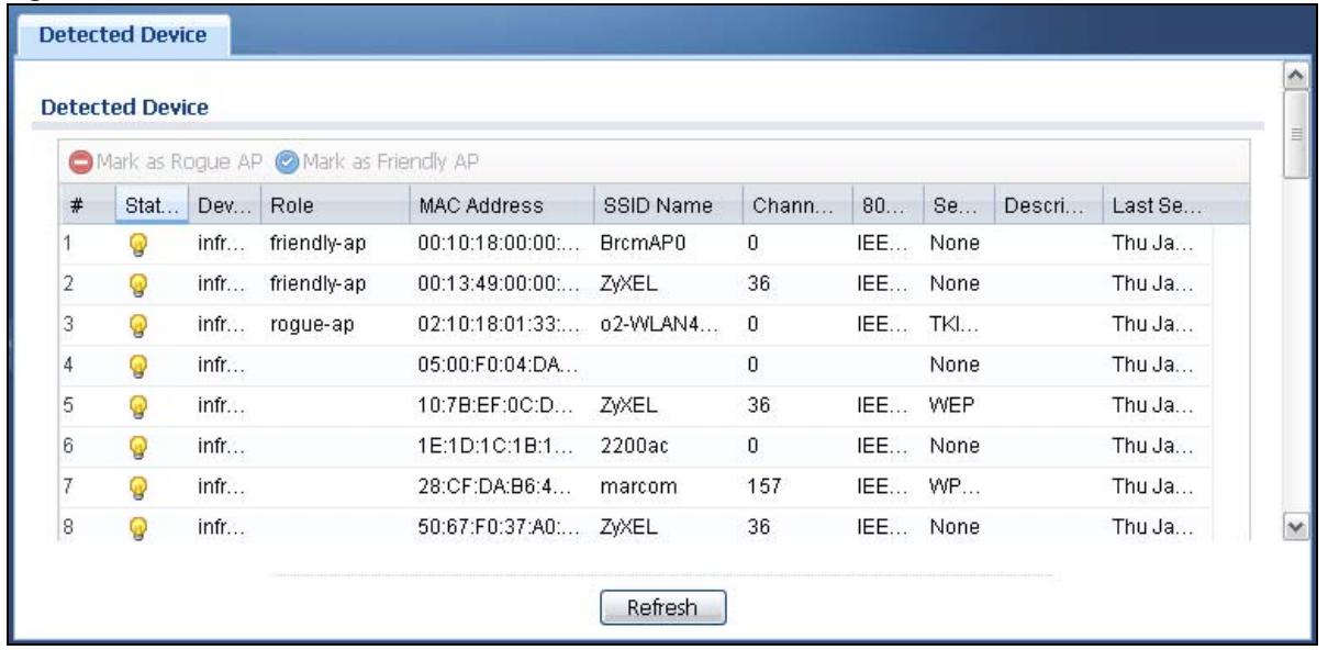
4.7 Detected Device
Use this screen to view information about suspected rogue APs. Click Monitor > Wireless > Detected Device to access this screen. Not all NWA/WACs support monitor mode and rogue APs detection.
Note: The radio or at least one of the NWA/WAC's radio must be set to monitor mode (in the Wireless > AP Management screen) in order to detect other wireless devices in its vicinity.
Figure 27 Monitor > Wireless > Detected Device
The following table describes the labels in this screen.
Table 28 Monitor > Wireless > Detected Device
| LABEL | DESCRIPTION |
| Mark as Rogue AP | Click this button to mark the selected AP as a rogue AP. A rogue AP can be contained in the Configuration > Wireless > MON Mode screen (Section 6.3 on page 73). |
| Mark as Friendly AP | Click this button to mark the selected AP as a friendly AP. For more on managing friendly APs, see the Configuration > Wireless > MON Mode screen (Section 6.3 on page 73). |
| # | This is the detected device's index number in this list. |
| Status | This indicates the detected device's status. |
| Device | This indicates the type of device detected. |
| Role | This indicates the detected device's role (such as friendly or rogue). |
| MAC Address | This indicates the detected device's MAC address. |
| SSID Name | This indicates the detected device's SSID. |
| Channel ID | This indicates the detected device's channel ID. |
| 802.11 Mode | This indicates the 802.11 mode (a/b/g/n) transmitted by the detected device. |
| Security | This indicates the encryption method (if any) used by the detected device. |
| Description | This displays the detected device's description. For more on managing friendly and rogue APs, see the Configuration > Wireless > MON Mode screen (Section 6.3 on page 73). |
| Last Seen | This indicates the last time the device was detected by the NWA/WAC. |
| Refresh | Click this to refresh the items displayed on this page. |
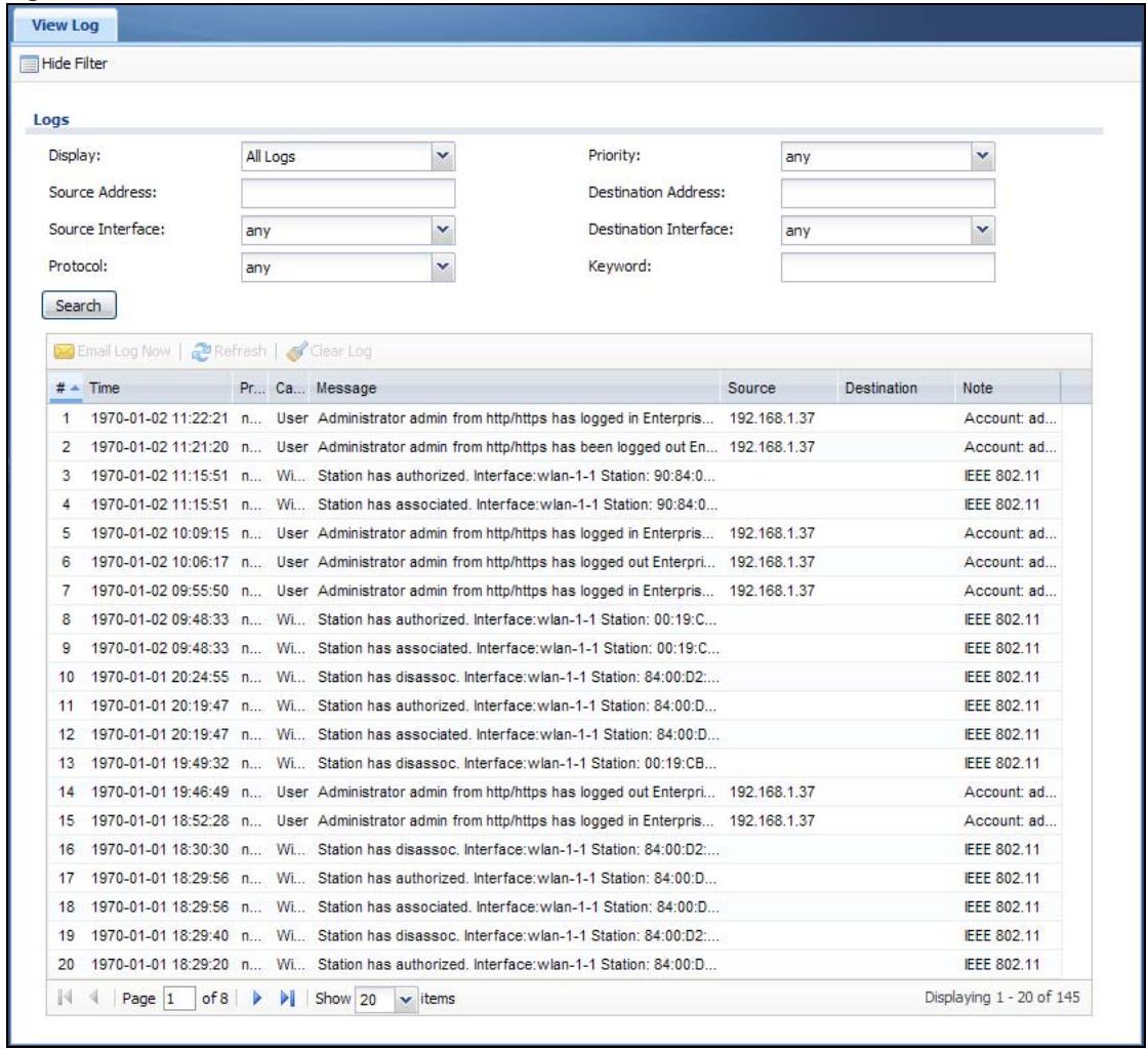
4.8 View Log
Log messages are stored in two separate logs, one for regular log messages and one for debugging messages. In the regular log, you can look at all the log messages by selecting All Logs, or you can select a specific category of log messages (for example, user). You can also look at the debugging log by selecting Debug Log. All debugging messages have the same priority.
To access this screen, click Monitor > Log. The log is displayed in the following screen.
Note: When a log reaches the maximum number of log messages, new log messages automatically overwrite existing log messages, starting with the oldest existing log message first.
Events that generate an alert (as well as a log message) display in red. Regular logs display in black. Click a column's heading cell to sort the table entries by that column's criteria. Click the heading cell again to reverse the sort order.
Figure 28 Monitor > Log > View Log
The following table describes the labels in this screen.
Table 29 Monitor > Log > View Log
| LABEL | DESCRIPTION |
| Show Filter / Hide Filter | Click this button to show or hide the filter settings.If the filter settings are hidden, the Display, Email Log Now, Refresh, and Clear Log fields are available.If the filter settings are shown, the Display, Priority, Source Address, Destination Address, Source Interface, Destination Interface, Protocol, Keyword, and Search fields are available. |
| Display | Select the category of log message(s) you want to view. You can also view All Logs at one time, or you can view the Debug Log. |
| Priority | This displays when you show the filter. Select the priority of log messages to display. The log displays the log messages with this priority or higher. Choices are: any, emerg, alert, crit, error, warn, notice, and info, from highest priority to lowest priority. This field is read-only if the Category is Debug Log. |
| Source Address | This displays when you show the filter. Type the source IP address of the incoming packet that generated the log message. Do not include the port in this filter. |
| Destination Address | This displays when you show the filter. Type the IP address of the destination of the incoming packet when the log message was generated. Do not include the port in this filter. |
| Source Interface | This displays when you show the filter. Select the source interface of the packet that generated the log message. |
| Destination Interface | This displays when you show the filter. Select the destination interface of the packet that generated the log message. |
| Protocol | This displays when you show the filter. Select a service protocol whose log messages you would like to see. |
| Keyword | This displays when you show the filter. Type a keyword to look for in the Message, Source, Destination and Note fields. If a match is found in any field, the log message is displayed. You can use up to 63 alphanumeric characters and the underscore, as well as punctuation marks ( )', ;;?! +.*/= #$% @; the period, double quotes, and brackets are not allowed. |
| Search | This displays when you show the filter. Click this button to update the log using the current filter settings. |
| Email Log Now | Click this button to send log messages to the Active e-mail addresses specified in the Send Log To field on the Configuration > Log & Report > Log Settings screen. |
| Refresh | Click this to update the list of logs. |
| Clear Log | Click this button to clear the whole log, regardless of what is currently displayed on the screen. |
| # | This field is a sequential value, and it is not associated with a specific log message. |
| Time | This field displays the time the log message was recorded. |
| Priority | This field displays the priority of the log message. It has the same range of values as the Priority field above. |
| Category | This field displays the log that generated the log message. It is the same value used in the Display and (other) Category fields. |
| Message | This field displays the reason the log message was generated. The text “[count=x]”, where x is a number, appears at the end of the Message field if log consolidation is turned on and multiple entries were aggregated to generate into this one. |
| Source | This field displays the source IP address and the port number in the event that generated the log message. |
| Source Interface | This field displays the source interface of the packet that generated the log message. |
| Destination | This field displays the destination IP address and the port number of the event that generated the log message. |
| Destination Interface | This field displays the destination interface of the packet that generated the log message. |
| Protocol | This field displays the service protocol in the event that generated the log message. |
| Note | This field displays any additional information about the log message. |
The Web Configurator saves the filter settings if you leave the View Log screen and return to it later.
CHAPTER 5 Network
5.1 Overview
This chapter describes how you can configure the management IP address and VLAN settings of your NWA/WAC.
The Internet Protocol (IP) address identifies a device on a network. Every networking device (including computers, servers, routers, printers, etc.) needs an IP address to communicate across the network. These networking devices are also known as hosts.
Figure 29 IP Setup
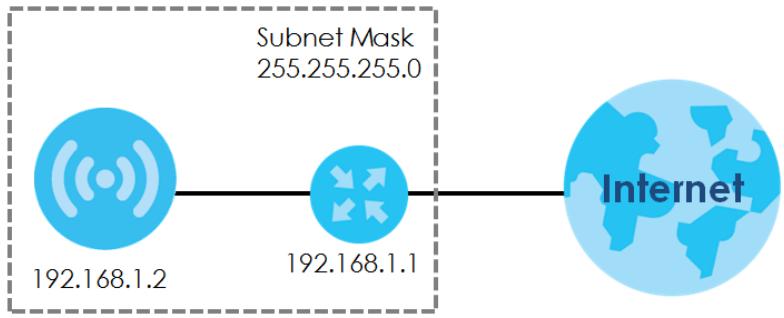
network
| Connection Type | Value | | --------------- | ----------- | | Subnet Mask | 255.255.255.0 | | Internet | 192.168.1.1 |The figure above illustrates one possible setup of your NWA/WAC. The gateway IP address is 192.168.1.1 and the managed IP address of the NWA/WAC is 192.168.1.2 (default), but if the NWA/WAC is assigned an IP address by a DHCP server, the default (192.168.1.2) will not be used. The gateway and the NWA/WAC must belong in the same IP subnet to be able to communicate with each other.
5.1.1 Management Mode
This discusses using the NWA/WAC in management mode, which determines whether the NWA/WAC is used in its standalone mode, or as part of a Control And Provisioning of Wireless Access Points (CAPWAP) network.
About CAPWAP
The NWA/WAC supports CAPWAP. This is Zyxel's implementation of the CAPWAP protocol (RFC 5415).
The CAPWAP data flow is protected by Datagram Transport Layer Security (DTLS).
The following figure illustrates a CAPWAP wireless network. You (U) configure the AP controller (C), which then automatically updates the configurations of the managed APs (M1 \~ M4).
Figure 30 CAPWAP Network Example
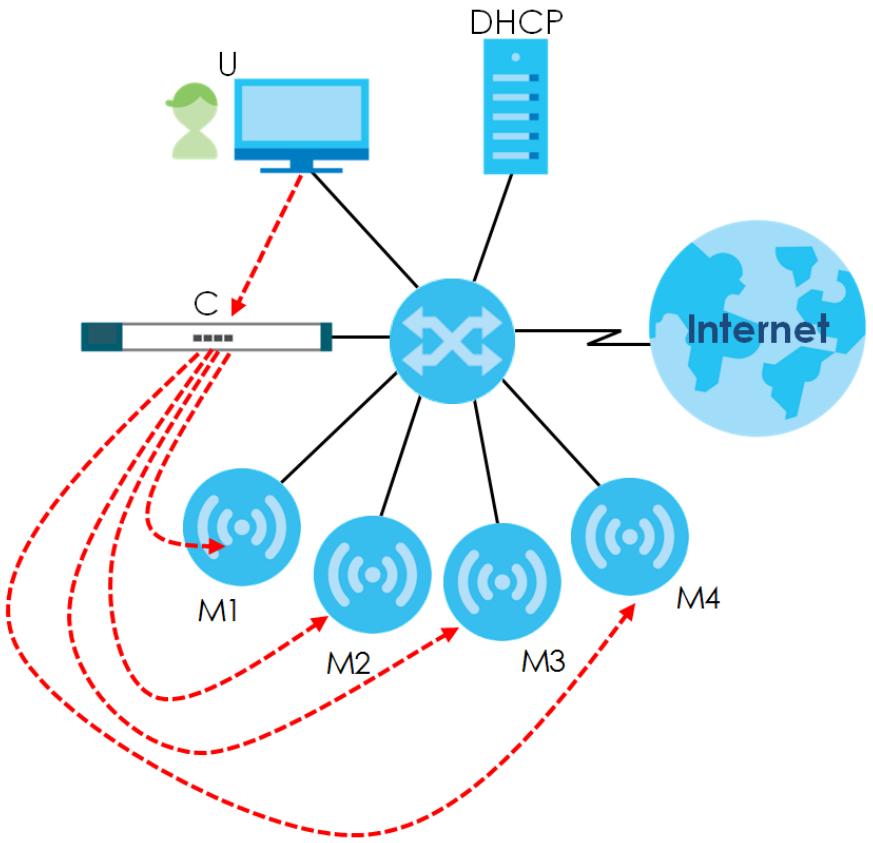
flowchart
graph TD
    U["User"] --> C["Central Node"]
    DHCP["DHCP"] --> C
    C --> M1["M1"]
    C --> M2["M2"]
    C --> M3["M3"]
    C --> M4["M4"]
    M1 --> M2
    M2 --> M3
    M3 --> M4
    M4 --> Internet["Internet"]
    style Internet fill:#cce5ff,stroke:#333
    style M1,M2,M3,M4 fill:#cce5ff,stroke:#333
Note: The NWA/WAC can be a standalone AP (default), or a CAPWAP managed AP.
CAPWAP Discovery and Management
The link between CAPWAP-enabled access points proceeds as follows:
1 An AP in managed AP mode joins a wired network (receives a dynamic IP address).
2 The AP sends out a discovery request, looking for a CAPWAP AP controller.
3 If there is an AP controller on the network, it receives the discovery request. If the AP controller is in Manual mode it adds the details of the AP to its Unmanaged Access Points list, and you decide which available APs to manage. If the AP controller is in Always Accept mode, it automatically adds the AP to its Managed Access Points list and provides the managed AP with default configuration information, as well as securely transmitting the DTLS pre-shared key. The managed AP is ready for association with wireless clients.
Managed AP Finds the Controller
A managed NWA/WAC can find the controller in one of the following ways:
- Manually specify the controller's IP address in the Web Configurator's AC (AP Controller) Discovery screen.
-
Get the controller's IP address from a DHCP server with the controller's IP address configured as option 138.
-
Get the controller's IP address from a DNS server SRV (Service) record.
- Broadcasting to discover the controller within the broadcast domain.
Note: The AP controller needs to have a static IP address. If it is a DHCP client, set the DHCP server to reserve an IP address for the AP controller.
CAPWAP and IP Subnets
By default, CAPWAP works only between devices with IP addresses in the same subnet.
However, you can configure CAPWAP to operate between devices with IP addresses in different subnets by doing the following.
- Activate DHCP. Your network's DHCP server must support option 138 defined in RFC 5415.
- Configure DHCP option 138 with the IP address of the CAPWAP AP controller on your network.
DHCP Option 138 allows the CAPWAP management request (from the AP in managed AP mode) to reach the AP controller in a different subnet, as shown in the following figure.
Figure 31 CAPWAP and DHCP Option 138
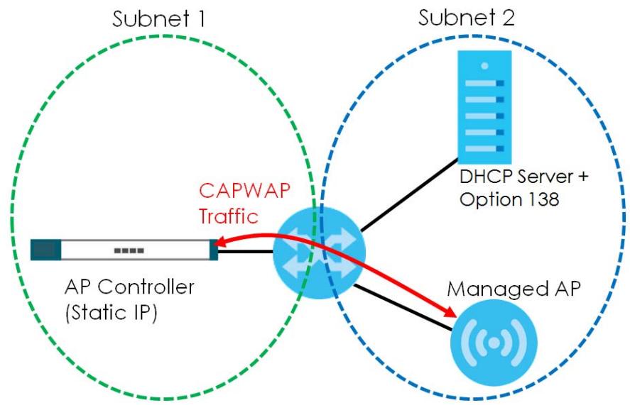
flowchart
graph TD
    A["AP Controller (Static IP)"] -->|CAPWAP Traffic| B((Center))
    B --> C["Managed AP"]
    C --> D["DHCP Server + Option 138"]
    style A fill:#f9f,stroke:#333
    style B fill:#ccf,stroke:#333
    style C fill:#cfc,stroke:#333
    style D fill:#fcc,stroke:#333
Notes on CAPWAP
This section lists some additional features of Zyxel's implementation of the CAPWAP protocol.
- When the AP controller uses its internal Remote Authentication Dial In User Service (RADIUS) server, managed APs also use the AP controller's authentication server to authenticate wireless clients.
- If a managed AP's link to the AP controller is broken, the managed AP continues to use the wireless settings with which it was last provided.
5.1.2 What You Can Do in this Chapter
- The IP Setting screen (Section 5.2 on page 63) configures the NWA/WAC's LAN IP address.
- The VLAN screen (Section 5.3 on page 64) configures the NWA/WAC's VLAN settings.
- The AC (AP Controller) Discovery screen (Section 5.3 on page 64) configures the NWA/WAC's AP Controller settings.
5.2 IP Setting
Use this screen to configure the IP address for your NWA/WAC. To access this screen, click Configuration > Network > IP Setting.
Figure 32 Configuration > Network > IP Setting (Retake screenshot)
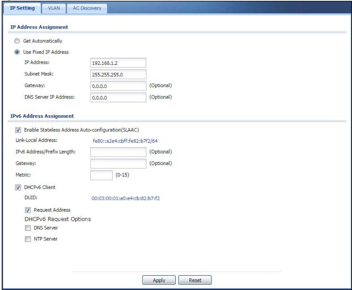
Each field is described in the following table.
Table 30 Configuration > Network > IP Setting
| LABEL | DESCRIPTION |
| IP Address Assignment | |
| Get Automatically | Select this to make the interface a DHCP client and automatically get the IP address, subnet mask, and gateway address from a DHCP server. |
| Use Fixed IP Address | Select this if you want to specify the IP address, subnet mask, and gateway manually. |
| IP Address | Enter the IP address for this interface. |
| Subnet Mask | Enter the subnet mask of this interface in dot decimal notation. The subnet mask indicates what part of the IP address is the same for all computers in the network. |
| Gateway | Enter the IP address of the gateway. The NWA/WAC sends packets to the gateway when it does not know how to route the packet to its destination. The gateway should be on the same network as the interface. |
| DNS Server IP Address | Enter the IP address of the DNS server. |
| IPv6 Address Assignment | |
| Enable Stateless Address Auto-configuration (SLAAC) | Select this to enable IPv6 stateless auto-configuration on the NWA/WAC. The NWA/WAC will generate an IPv6 address itself from a prefix obtained from an IPv6 router in the network. |
| Link-Local Address | This displays the IPv6 link-local address and the network prefix that the NWA/WAC generates itself for the LAN interface. |
| IPv6 Address/ Prefix Length | Enter the IPv6 address and the prefix length for the LAN interface if you want to use a static IP address. This field is optional.The prefix length indicates what the left-most part of the IP address is the same for all computers in the network, that is, the network address. |
| Gateway | Enter the IPv6 address of the default outgoing gateway using colon (:) hexadecimal notation. |
| Metric | Enter the priority of the gateway (if any) on the LAN interface. The NWA/WAC decides which gateway to use based on this priority. The lower the number, the higher the priority. If two or more gateways have the same priority, the NWA/WAC uses the one that was configured first. Enter zero to set the metric to 1024 for IPv6. |
| DHCPv6 Client | Select this option to set the NWA/WAC to act as a DHCPv6 client. |
| DUID | This field displays the DHCP Unique IDentifier (DUID) of the NWA/WAC, which is unique and used for identification purposes when the NWA/WAC is exchanging DHCPv6 messages with others. SeeAppendix B on page 212for more information. |
| Request Address | Select this option to get an IPv6 address from the DHCPv6 server. |
| DHCPv6 Request Options | Select this option to determine what additional information to get from the DHCPv6 server. |
| DNS Server | Select this option to obtain the IP address of the DNS server. |
| NTP Server | Select this option to obtain the IP address of the NTP server. |
| Apply | ClickApplyto save your changes back to the NWA/WAC. |
| Reset | ClickResetto return the screen to its last-saved settings. |
5.3 VLAN
This section discusses how to configure the NWA/WAC's VLAN settings.
Figure 33 Management VLAN Setup
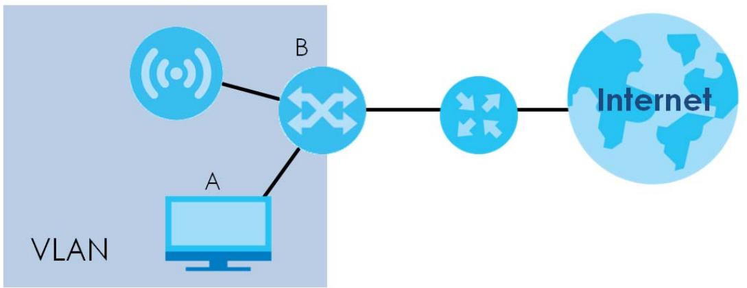
flowchart
graph LR
    A["Computer"] -->|A| B["Router"]
    B --> C["Internet"]
    style A fill:#cce5ff,stroke:#333
    style B fill:#cce5ff,stroke:#333
    style C fill:#cce5ff,stroke:#333
    note bottom left of A: VLAN
In the figure above, to access and manage the NWA/WAC from computer A, the NWA/WAC and switch B's ports to which computer A and the NWA/WAC are connected should be in the same VLAN.
A Virtual Local Area Network (VLAN) allows a physical network to be partitioned into multiple logical networks. Devices on a logical network belong to one group. A device can belong to more than one group. With VLAN, a device cannot directly talk to or hear from devices that are not in the same group(s); the traffic must first go through a router.
VLAN also increases network performance by limiting broadcasts to a smaller and more manageable logical broadcast domain. In traditional switched environments, all broadcast packets go to each and every individual port. With VLAN, all broadcasts are confined to a specific broadcast domain.
IEEE 802.1Q Tag
The IEEE 802.1Q standard defines an explicit VLAN tag in the MAC header to identify the VLAN membership of a frame across bridges. A VLAN tag includes the 12-bit VLAN ID and 3-bit user priority. The VLAN ID associates a frame with a specific VLAN and provides the information that devices need to process the frame across the network.
Use this screen to configure the VLAN settings for your NWA/WAC. To access this screen, click Configuration > Network > VLAN.
Figure 34 Configuration > Network > VLAN
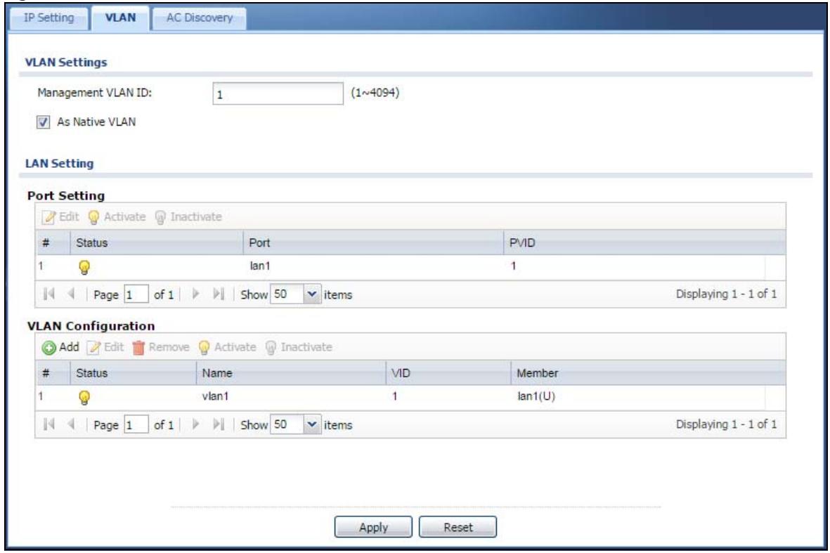
Each field is described in the following table.
Table 31 Configuration > Network > VLAN
| LABEL | DESCRIPTION |
| VLAN Settings | |
| Management VLAN ID | Enter a VLAN ID for the NWA/WAC. |
| As Native VLAN | Select this option to treat this VLAN ID as a VLAN created on the NWA/WAC and not one assigned to it from outside the network. |
| LAN Setting | |
| Port Setting | |
| Edit | Double-click an entry or select it and click Edit to open a screen where you can modify the entry's settings. In some tables you can just click a table entry and edit it directly in the table. For those types of tables small red triangles display for table entries with changes that you have not yet applied. |
| Activate/ Inactivate | To turn on an entry, select it and click Activate. To turn off an entry, select it and click Inactivate. |
| # | This is the index number of the port. |
| Status | This field indicates whether the port is enabled (a yellow bulb) or not (a gray bulb). |
| Port | This field displays the name of the port. |
| PVID | This field displays the port number of the VLAN ID. |
| VLAN Configuration | |
| Add | Click this to create a new entry. For features where the entry's position in the numbered list is important (features where the NWA/WAC applies the table's entries in order like the SSID for example), you can select an entry and click Add to create a new entry after the selected entry. |
| Edit | Double-click an entry or select it and click Edit to open a screen where you can modify the entry's settings. In some tables you can just click a table entry and edit it directly in the table. For those types of tables small red triangles display for table entries with changes that you have not yet applied. |
| Remove | To remove an entry, select it and click Remove. The NWA/WAC confirms you want to remove it before doing so. |
| Activate/Inactivate | To turn on an entry, select it and click Activate. To turn off an entry, select it and click Inactivate. |
| # | This is the index number of the VLAN ID |
| Status | This field indicates whether the VLAN is enabled (a yellow bulb) or not (a gray bulb). |
| Name | This field displays the name of each VLAN. |
| VID | This field displays the VLAN ID. |
| Member | This field displays the VLAN membership to which the port belongs. |
| Apply | Click Apply to save your changes back to the NWA/WAC. |
| Reset | Click Reset to return the screen to its last-saved settings. |
5.4 AC (AP Controller) Discovery
This section discusses how to configure the NWA/WAC's AC (AP Controller) Discovery settings. You can have the NWA/WAC managed by an AP controller on your network. When you do this, the NWA/WAC can be configured ONLY by the AP controller. See Section 5.1.1 on page 60 for more information on management mode and AP Controller.
Note: The AC(AP Controller) Discovery settings are not available in the NWA1123-ACv2 and NWA1123-AC PRO.
If you want to return the NWA/WAC to standalone AP mode, you can do one of the two following options:
- Press the Reset button.
- Check the AP controller for the NWA/WAC's IP address and use FTP to upload the default configuration file to the NWA/WAC. You can get the configuration file at conf/system-default.conf. You must reboot the device after uploading the configuration file.
To access the Controller Discover screen, click Configuration > Network > AC Discovery.
Figure 35 Configuration > Network > AC Discovery
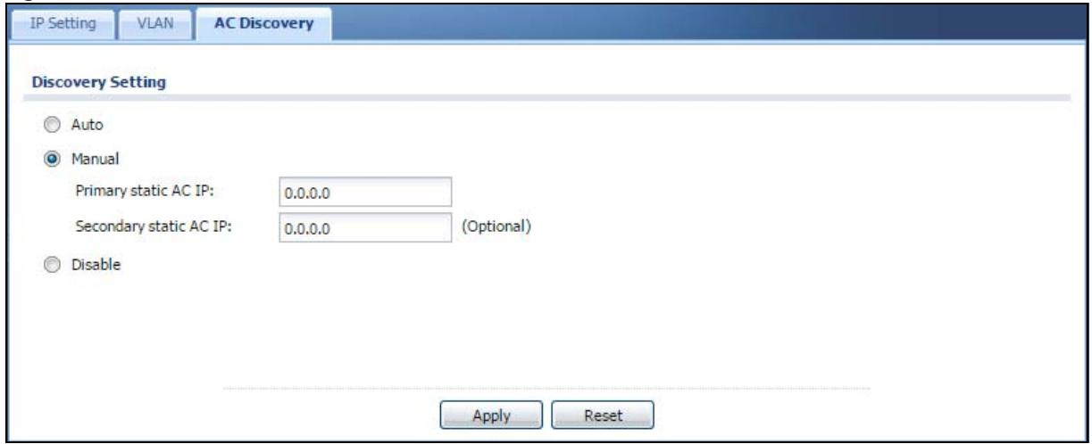
Each field is described in the following table.
Table 32 Configuration > Network > AC Discovery
| LABEL | DESCRIPTION |
| Discovery Setting | |
| Auto | Select this option to use DHCP option 138/DNS SRV record/Broadcast to get the AP controller's IP address. If the NWA/WAC and a Zyxel AP controller, such as the NXC2500 or NXC5500, are in the same subnet, it will be managed by the controller automatically. |
| Manual | Select this option and enter the IP address of the AP controller manually. This is necessary when the AP Controller is not in the same subnet and you want it to manage the NWA/WAC. |
| Primary / Secondary Static AC IP | Specify the primary and secondary IP address of the AP controller to which the NWA/WAC connects. |
| Disable | Select this to manage the NWA/WAC using its own web configurator, neither managing nor managed by other devices. Please note if an AP Controller is in the same subnet, you will need to click Disable if you do not want the NWA/WAC to be managed. |
| Apply | Click Apply to save the information entered in this screen.If you select Auto or Manual, the AP controller uploads the firmware package for managed AP mode to the NWA/WAC and you cannot log in as the web configurator is disabled; you must manage the NWA/WAC through the AP controller on your network. |
| Reset | Click Reset to return the screen to its last-saved settings. |
6.1 Overview
This chapter discusses how to configure the wireless network settings in your NWA/WAC.
The following figure provides an example of a wireless network.
Figure 36 Example of a Wireless Network
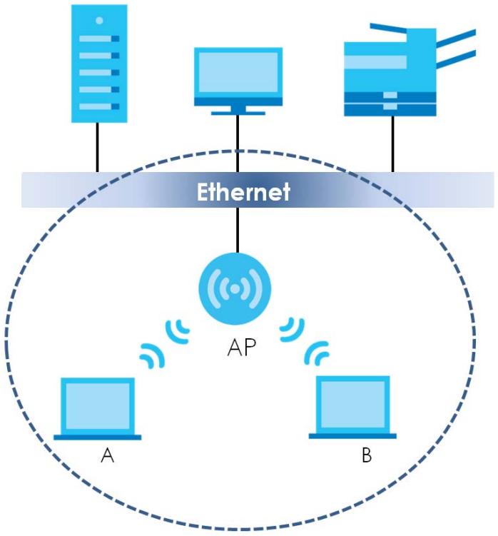
flowchart
graph TD
    A["Server"] --> E["Ethernet"]
    B["Computer"] --> E
    C["Server"] --> E
    D["A"] --> E
    E --> F["AP"]
    F --> G["B"]
    F --> H["A"]
    style E fill:#f9f,stroke:#333
    style F fill:#ccf,stroke:#333
    style G fill:#cfc,stroke:#333
    style H fill:#fcc,stroke:#333
The wireless network is the part in the blue circle. In this wireless network, devices A and B are called wireless clients. The wireless clients use the access point (AP) to interact with other devices (such as the printer) or with the Internet. Your NWA/WAC is the AP.
6.1.1 What You Can Do in this Chapter
- The AP Management screen (Section 6.2 on page 70) manages the NWA/WAC's general wireless settings.
- The MON Mode screen (Section 6.3 on page 73) allows you to assign APs either to the rogue AP list or the friendly AP list.
- The Load Balancing screen (Section 6.4 on page 75) configures network traffic load balancing between the APs and the NWA/WAC.
- The DCS screen (Section 6.5 on page 78) configures dynamic radio channel selection.
6.1.2 What You Need to Know
The following terms and concepts may help as you read this chapter.
Station / Wireless Client
A station or wireless client is any wireless-capable device that can connect to an AP using a wireless signal.
Dynamic Channel Selection (DCS)
Dynamic Channel Selection (DCS) is a feature that allows an AP to automatically select the radio channel upon which it broadcasts by scanning the area around it and determining what channels are currently being used by other devices.
Load Balancing (Wireless)
Wireless load balancing is the process where you limit the number of connections allowed on an wireless access point (AP) or you limit the amount of wireless traffic transmitted and received on it so the AP does not become overloaded.
6.2 AP Management
Use this screen to manage the NWA/WAC's general wireless settings. Click Configuration > Wireless > AP Management to access this screen.
Figure 37 Configuration > Wireless > AP Management
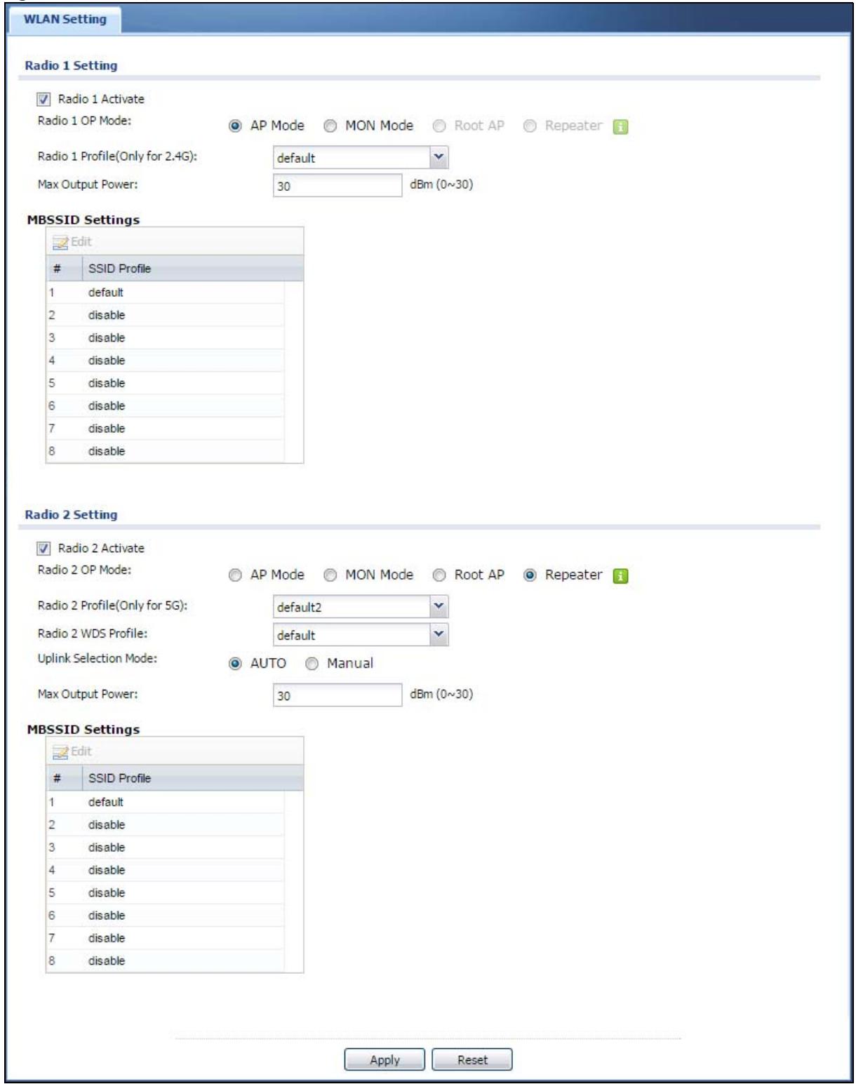
Each field is described in the following table.
Table 33 Configuration > Wireless > AP Management
| LABEL | DESCRIPTION |
| Radio 1 Setting | |
| Radio 1 Activate | Select the check box to enable the NWA/WAC's first (default) radio. |
| Radio 1 OP Mode | Select the operating mode for radio 1.AP Mode means the radio can receive connections from wireless clients and pass their data traffic through to the NWA/WAC to be managed (or subsequently passed on to an upstream gateway for managing).MON Mode means the radio monitors the broadcast area for other APs, then passes their information on to the NWA/WAC where it can be determined if those APs are friendly or rogue. If a radio is set to this mode it cannot receive connections from wireless clients.Root AP means the radio acts as an AP and also supports the wireless connections with other APs (in repeater mode) to form a WDS (Wireless Distribution System) to extend its wireless network.Repeater means the radio can establish a wireless connection with other APs (in either root AP or repeater mode) to form a WDS. |
| Radio 1 Profile | Select the radio profile the radio uses.Note: You can only apply a 2.4G AP radio profile to radio 1. Otherwise, the first radio will not be working. |
| Radio 1 WDS Profile | This field is available only when the radio is in Root AP or Repeater mode.Select the WDS profile the radio uses to connect to a root AP or repeater. |
| Uplink Selection Mode | This field is available only when the radio is in Repeater mode.Select AUTO to have the NWA/WAC automatically use the settings in the applied WDS profile to connect to a root AP or repeater.Select Manual to have the NWA/WAC connect to the root AP or repeater with the MAC address specified in the Radio 1 Uplink MAC Address field. |
| Max Output Power | Enter the maximum output power (between 0 to 30 dBm) of the NWA/WAC in this field. If there is a high density of APs in an area, decrease the output power of the NWA/WAC to reduce interference with other APs.Note: Reducing the output power also reduces the NWA/WAC's effective broadcast radius. |
| MBSSID Settings | |
| Edit | Double-click an entry or select it and click Edit to open a screen where you can modify the entry's settings. In some tables you can just click a table entry and edit it directly in the table. For those types of tables small red triangles display for table entries with changes that you have not yet applied. |
| # | This field shows the index number of the SSID |
| SSID Profile | This field displays the SSID profile that is associated with the radio profile. |
| Radio 2 Setting | |
| Radio 2 Activate | This displays if the NWA/WAC has a second radio.Select the check box to enable the NWA/WAC's second radio. |
| Radio 2 OP Mode | This displays if the NWA/WAC has a second radio. Select the operating mode for radio 2.AP Mode means the radio can receive connections from wireless clients and pass their data traffic through to the NWA/WAC to be managed (or subsequently passed on to an upstream gateway for managing).MON Mode means the radio monitors the broadcast area for other APs, then passes their information on to the NWA/WAC where it can be determined if those APs are friendly or rogue. If a radio is set to this mode it cannot receive connections from wireless clients.Root AP means the radio acts as an AP and also supports the wireless connections with other APs (in repeater mode) to form a WDS to extend its wireless network.Repeater means the radio can establish a wireless connection with other APs (in either root AP or repeater mode) to form a WDS. |
| Radio 2 Profile | This displays if the NWA/WAC has a second radio. Select the radio profile the radio uses.Note: You can only apply a 5G AP radio profile to radio 2. Otherwise, the second radio will not be working. |
| Radio 2 WDS Profile | This field is available only when the radio is in Root AP or Repeater mode.Select the WDS profile the radio uses to connect to a root AP or repeater. |
| Uplink Selection Mode | This field is available only when the radio is in Repeater mode.Select AUTO to have the NWA/WAC automatically use the settings in the applied WDS profile to connect to a root AP or repeater.Select Manual to have the NWA/WAC connect to the root AP or repeater with the MAC address specified in the Radio 2 Uplink MAC Address field. |
| Max Output Power | Enter the maximum output power (between 0 to 30 dBm) of the NWA/WAC in this field. If there is a high density of APs in an area, decrease the output power of the NWA/WAC to reduce interference with other APs.Note: Reducing the output power also reduces the NWA/WAC's effective broadcast radius. |
| MBSSID Settings | |
| Edit | Double-click an entry or select it and click Edit to open a screen where you can modify the entry's settings. In some tables you can just click a table entry and edit it directly in the table. For those types of tables small red triangles display for table entries with changes that you have not yet applied. |
| # | This field shows the index number of the SSID |
| SSID Profile | This field shows the SSID profile that is associated with the radio profile. |
| Apply | Click Apply to save your changes back to the NWA/WAC. |
| Reset | Click Reset to return the screen to its last-saved settings. |
6.3 MON Mode
Use this screen to assign APs either to the rogue AP list or the friendly AP list. A rogue AP is a wireless access point operating in a network's coverage area that is not under the control of the network administrator, and which can potentially open up holes in a network's security.
Click Configuration > Wireless > MON Mode to access this screen.
Figure 38 Configuration > Wireless > MON Mode
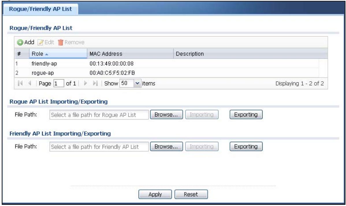
Each field is described in the following table.
Table 34 Configuration > Wireless > MON Mode
| LABEL | DESCRIPTION |
| Rogue/Friendly AP List | |
| Add | Click this button to add an AP to the list and assign it either friendly or rogue status. |
| Edit | Select an AP in the list to edit and reassign its status. |
| Remove | Select an AP in the list to remove. |
| # | This field is a sequential value, and it is not associated with any interface. |
| Role | This field indicates whether the selected AP is a rogue-ap or a friendly-ap. To change the AP's role, click the Edit button. |
| MAC Address | This field indicates the AP's radio MAC address. |
| Description | This field displays the AP's description. You can modify this by clicking the Edit button. |
| Importing/Exporting | These controls allow you to export the current list of rogue and friendly APs or import existing lists. |
| File Path / Browse / Importing | Enter the file name and path of the list you want to import or click the Browse button to locate it. Once the File Path field has been populated, click Importing to bring the list into the NWA/WAC.You need to wait a while for the importing process to finish. |
| Exporting | Click this button to export the current list of either rogue APs or friendly APS. |
| Apply | Click Apply to save your changes back to the NWA/WAC. |
| Reset | Click Reset to return the screen to its last-saved settings. |
6.3.1 Add/Edit Rogue/Friendly List
Click Add or select an AP and click the Edit button in the Configuration > Wireless > MON Mode table to display this screen.
Figure 39 Configuration > Wireless > MON Mode > Add/Edit Rogue/Friendly AP List
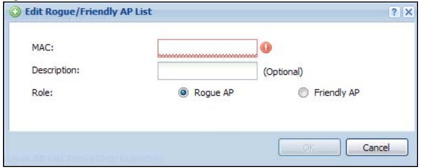
Each field is described in the following table.
Table 35 Configuration > Wireless > MON Mode > Add/Edit Rogue/Friendly AP List
| LABEL | DESCRIPTION |
| MAC | Enter the MAC address of the AP you want to add to the list. A MAC address is a unique hardware identifier in the following hexadecimal format: xx:xx:xx:xx:xx where xx is a hexadecimal number separated by colons. |
| Description | Enter up to 60 characters for the AP's description. Spaces and underscores are allowed. |
| Role | Select either Rogue AP or Friendly AP for the AP's role. |
| OK | Click OK to save your changes back to the NWA/WAC. |
| Cancel | Click Cancel to close the window with changes unsaved. |
6.4 Load Balancing
Use this screen to configure wireless network traffic load balancing between the APs on your network. Click Configuration > Wireless > Load Balancing to access this screen.
Figure 40 Configuration > Wireless > Load Balancing

Each field is described in the following table.
Table 36 Configuration > Wireless > Load Balancing
| LABEL | DESCRIPTION |
| Enable Load Balancing | Select this to enable load balancing on the NWA/WAC.Use this section to configure wireless network traffic load balancing between the managd APs in this group. |
| Mode | Select a mode by which load balancing is carried out.Select By Station Number to balance network traffic based on the number of specified stations connected to the NWA/WAC.Select By Traffic Level to balance network traffic based on the volume generated by the stations connected to the NWA/WAC.Select By Smart Classroom to balance network traffic based on the number of specified stations connected to the NWA/WAC. The NWA/WAC ignores association request and authentication request packets from any new station when the maximum number of stations is reached.If you select By Station Number or By Traffic Level, once the threshold is crossed (either the maximum station numbers or with network traffic), the NWA/WAC delays association request and authentication request packets from any new station that attempts to make a connection. This allows the station to automatically attempt to connect to another, less burdened AP if one is available. |
| Max Station Number | Enter the threshold number of stations at which the NWA/WAC begins load balancing its connections. |
| Traffic Level | Select the threshold traffic level at which the NWA/WAC begins load balancing its connections (Low, Medium, High).The maximum bandwidth allowed for each level is:Low-11 Mbps,Medium-23 MbpsHigh-35M bps |
| Disassociate station when overloaded | This function is enabled by default and the disassociation priority is always Signal Strength when you set Mode to By Smart Classroom.Select this option to disassociate wireless clients connected to the AP when it becomes overloaded. If you do not enable this option, then the AP simply delays the connection until it can afford the bandwidth it requires, or it transfers the connection to another AP within its broadcast radius.The disassociation priority is determined automatically by the NWA/WAC and is as follows:Idle Timeout - Devices that have been idle the longest will be kicked first. If none of the connected devices are idle, then the priority shifts to Signal Strength.Signal Strength - Devices with the weakest signal strength will be kicked first.Note: If you enable this function, you should ensure that there are multiple APs within the broadcast radius that can accept any rejected or kicked wireless clients; otherwise, a wireless client attempting to connect to an overloaded AP will be disassociated permanently and never be allowed to connect. |
| Apply | Click Apply to save your changes back to the NWA/WAC. |
| Reset | Click Reset to return the screen to its last-saved settings. |
6.4.1 Disassociating and Delaying Connections
When your AP becomes overloaded, there are two basic responses it can take. The first one is to “delay” a client connection. This means that the AP withholds the connection until the data transfer throughput is lowered or the client connection is picked up by another AP. If the client is picked up by another AP then the original AP cannot resume the connection.
For example, here the AP has a balanced bandwidth allotment of 6 Mbps. If laptop R connects and it pushes the AP over its allotment, say to 7 Mbps, then the AP delays the red laptop's connection until it can afford the bandwidth or the laptop is picked up by a different AP with bandwidth to spare.
Figure 41 Delaying a Connection
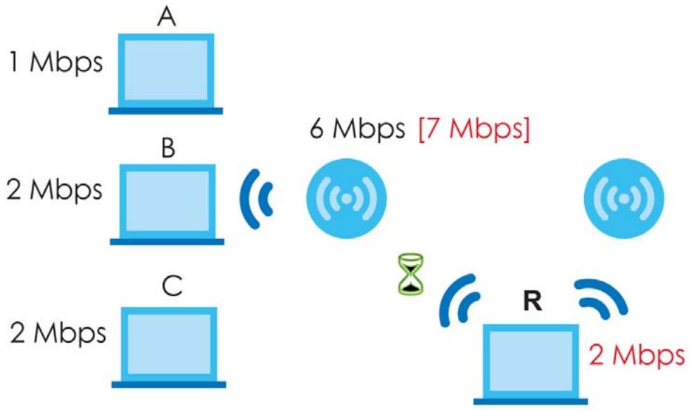
flowchart
graph TD
    A["Device A"] -->|1 Mbps| B["Device B"]
    B -->|2 Mbps| C["Device C"]
    C -->|2 Mbps| D["Router R"]
    D -->|6_Mbps["7 Mbps"]| E["Central Network Device"]
    style A fill:#cce5ff,stroke:#333
    style B fill:#cce5ff,stroke:#333
    style C fill:#cce5ff,stroke:#333
    style D fill:#cce5ff,stroke:#333
    style E fill:#cce5ff,stroke:#333
The second response your AP can take is to kick the connections that are pushing it over its balanced bandwidth allotment.
Figure 42 Kicking a Connection

flowchart
graph TD
    A["Device A"] -->|1 Mbps| B["Device B"]
    B -->|2 Mbps| C["Device C"]
    C -->|2 Mbps| R["Router R"]
    style A fill:#cce5ff,stroke:#333
    style B fill:#cce5ff,stroke:#333
    style C fill:#cce5ff,stroke:#333
    style R fill:#cce5ff,stroke:#333
    note right of B "6_Mbps["7 Mbps"]"
    note right of R "2 Mbps"
Connections are kicked based on either idle timeout or signal strength. The NWA/WAC first looks to see which devices have been idle the longest, then starts kicking them in order of highest idle time. If no connections are idle, the next criteria the NWA/WAC analyzes is signal strength. Devices with the weakest signal strength are kicked first.
6.5 DCS
Use this screen to configure dynamic radio channel selection. Click Configuration > Wireless > DCS to access this screen.
Figure 43 Configuration > Wireless > DCS
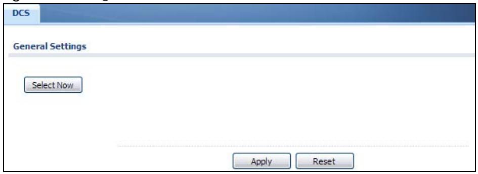
Each field is described in the following table.
Table 37 Configuration > Wireless > DCS
| LABEL | DESCRIPTION |
| Select Now | Click this to have the NWA/WAC scan for and select an available channel immediately. |
| Apply | Click Apply to save your changes back to the NWA/WAC. |
| Reset | Click Reset to return the screen to its last-saved settings. |
6.6 Technical Reference
The following section contains additional technical information about the features described in this chapter.
Dynamic Channel Selection
When numerous APs broadcast within a given area, they introduce the possibility of heightened radio interference, especially if some or all of them are broadcasting on the same radio channel. If the interference becomes too great, then the network administrator must open his AP configuration options and manually change the channel to one that no other AP is using (or at least a channel that has a lower level of interference) in order to give the connected stations a minimum degree of interference. Dynamic channel selection frees the network administrator from this task by letting the AP do it automatically. The AP can scan the area around it looking for the channel with the least amount of interference.
In the 2.4 GHz spectrum, each channel from 1 to 13 is broken up into discrete 22 MHz segments that are spaced 5 MHz apart. Channel 1 is centered on 2.412 GHz while channel 13 is centered on 2.472 GHz.
Figure 44 An Example Three-Channel Deployment
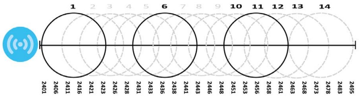
radar
| Category | Value | | -------- | ----- | | 1 | 2401 | | 2 | 2406 | | 3 | 2411 | | 4 | 2416 | | 5 | 2421 | | 6 | 2423 | | 7 | 2426 | | 8 | 2428 | | 9 | 2431 | | 10 | 2433 | | 11 | 2436 | | 12 | 2438 | | 13 | 2441 | | 14 | 2443 | | 15 | 2446 | | 16 | 2448 | | 17 | 2451 | | 18 | 2453 | | 19 | 2456 | | 20 | 2458 | | 21 | 2461 | | 22 | 2463 | | 23 | 2468 | | 24 | 2473 | | 25 | 2478 | | 26 | 2483 | | 27 | 2495 |Three channels are situated in such a way as to create almost no interference with one another if used exclusively: 1, 6 and 11. When an AP broadcasts on any of these three channels, it should not interfere with neighboring APs as long as they are also limited to same trio.
Figure 45 An Example Four-Channel Deployment
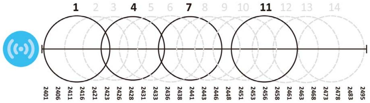
radar
| Label | Value | |-------|-------| | 1 | 2401 | | 2 | 2406 | | 3 | 2411 | | 4 | 2416 | | 5 | 2421 | | 6 | 2423 | | 7 | 2428 | | 8 | 2431 | | 9 | 2433 | | 10 | 2436 | | 11 | 2438 | | 12 | 2441 | | 13 | 2443 | | 14 | 2446 | | | 2448 | | | 2451 | | | 2453 | | | 2456 | | | 2458 | | | 2461 | | | 2463 | | | 2468 | | | 2473 | | | 2478 | | | 2483 | | | 2495 |However, some regions require the use of other channels and often use a safety scheme with the following four channels: 1, 4, 7 and 11. While they are situated sufficiently close to both each other and the three so-called “safe” channels (1,6 and 11) that interference becomes inevitable, the severity of it is dependent upon other factors: proximity to the affected AP, signal strength, activity, and so on.
Finally, there is an alternative four channel scheme for ETSI, consisting of channels 1, 5, 9, 13. This offers significantly less overlap that the other one.
Figure 46 An Alternative Four-Channel Deployment
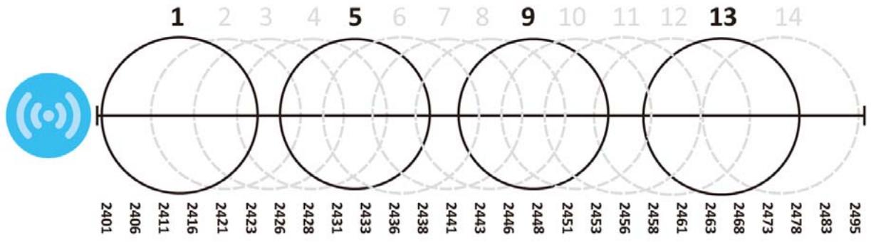
radar
| Category | Value | | -------- | ----- | | 1 | 2401 | | 2 | 2406 | | 3 | 2411 | | 4 | 2416 | | 5 | 2421 | | 6 | 2426 | | 7 | 2431 | | 8 | 2433 | | 9 | 2436 | | 10 | 2438 | | 11 | 2441 | | 12 | 2443 | | 13 | 2446 | | 14 | 2448 | | 15 | 2451 | | 16 | 2453 | | 17 | 2456 | | 18 | 2458 | | 19 | 2461 | | 20 | 2463 | | 21 | 2468 | | 22 | 2473 | | 23 | 2478 | | 24 | 2495 |Load Balancing
Because there is a hard upper limit on an AP's wireless bandwidth, load balancing can be crucial in areas crowded with wireless users. Rather than let every user connect and subsequently dilute the
available bandwidth to the point where each connecting device receives a meager trickle, the load balanced AP instead limits the incoming connections as a means to maintain bandwidth integrity.
There are three kinds of wireless load balancing available on the NWA/WAC:
Load balancing by station number limits the number of devices allowed to connect to your AP. If you know exactly how many stations you want to let connect, choose this option.
For example, if your company's graphic design team has their own AP and they have 10 computers, you can load balance for 10. Later, if someone from the sales department visits the graphic design team's offices for a meeting and he tries to access the network, his computer's connection is delayed, giving it the opportunity to connect to a different, neighboring AP. If he still connects to the AP regardless of the delay, then the AP may boot other people who are already connected in order to associate with the new connection.
Load balancing by smart classroom also limits the number of devices allowed to connect to your AP. But any new connections will be just rejected when the AP is overloaded.
Load balancing by traffic level limits the number of connections to the AP based on maximum bandwidth available. If you are uncertain as to the exact number of wireless connections you will have then choose this option. By setting a maximum bandwidth cap, you allow any number of devices to connect as long as their total bandwidth usage does not exceed the configured bandwidth cap associated with this setting. Once the cap is hit, any new connections are rejected or delayed provided that there are other APs in range.
Imagine a coffee shop in a crowded business district that offers free wireless connectivity to its customers. The coffee shop owner can't possibly know how many connections his AP will have at any given moment. As such, he decides to put a limit on the bandwidth that is available to his customers but not on the actual number of connections he allows. This means anyone can connect to his wireless network as long as the AP has the bandwidth to spare. If too many people connect and the AP hits its bandwidth cap then all new connections must basically wait for their turn or get shunted to the nearest identical AP.
7.1 Overview
This chapter describes how to set up user accounts and user settings for the NWA/WAC.
7.1.1 What You Can Do in this Chapter
- The User screen (see Section 7.2 on page 82) provides a summary of all user accounts.
- The Setting screen (see Section 7.3 on page 84) controls default settings, login settings, lockout settings, and other user settings for the NWA/WAC.
7.1.2 What You Need To Know
The following terms and concepts may help as you read this chapter.
User Account
A user account defines the privileges of a user logged into the NWA/WAC. User accounts are used in controlling access to configuration and services in the NWA/WAC.
User Types
These are the types of user accounts the NWA/WAC uses.
Table 38 Types of User Accounts
| TYPE | ABILITIES | LOGIN METHOD(S) |
| Admin Users | ||
| admin | Change NWA/WAC configuration (web, CLI) | WWW, TELNET, SSH, FTP |
| limited-admin | Look at NWA/WAC configuration (web, CLI)Perform basic diagnostics (CLI) | WWW, TELNET, SSH |
| Access Users | ||
| user | Used for the embedded RADIUS server and SNMPv3 user accessBrowse user-mode commands (CLI) | |
Note: The default admin account is always authenticated locally, regardless of the authentication method setting.
7.2 User Summary
The User screen provides a summary of all user accounts. To access this screen click Configuration > Object > User.
Figure 47 Configuration > Object > User
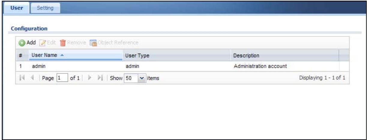
The following table describes the labels in this screen.
Table 39 Configuration > Object > User
| LABEL | DESCRIPTION |
| Add | Click this to create a new entry. |
| Edit | Double-click an entry or select it and click Edit to open a screen where you can modify the entry's settings. |
| Remove | To remove an entry, select it and click Remove. The NWA/WAC confirms you want to remove it before doing so. |
| Object Reference | Select an entry and click Object Reference to open a screen that shows which settings use the entry. |
| # | This field is a sequential value, and it is not associated with a specific user. |
| User Name | This field displays the user name of each user. |
| User Type | This field displays type of user this account was configured as.admin - this user can look at and change the configuration of the NWA/WACLimited-admin - this user can look at the configuration of the NWA/WAC but not to change ituser - this user has access to the NWA/WAC's services but cannot look at the configuration |
| Description | This field displays the description for each user. |
7.2.1 Add/Edit User
The User Add/Edit screen allows you to create a new user account or edit an existing one.
7.2.1.1 Rules for User Names
Enter a user name from 1 to 31 characters.
The user name can only contain the following characters:
• Alphanumeric A-z 0-9 (there is no unicode support)
- _ [underscores]
- [dashes]
The first character must be alphabetical (A-Z a-z), an underscore (_), or a dash (-). Other limitations on user names are:
- User names are case-sensitive. If you enter a user 'bob' but use 'BOB' when connecting via CIFS or FTP, it will use the account settings used for 'BOB' not 'bob'.
- User names have to be different than user group names.
• Here are the reserved user names:
- adm
- admin
- any
- bin
- daemon
- debug
- devicehaecived
ftp
- games
- halt
- ldap-users
• lp
- news
- nobody
- operator
- radius-users
- root
- shutdown
- sshd
- sync
- uucp
- zyxel
To access this screen, go to the User screen, and click Add or Edit.
Figure 48 Configuration > Object > User > Add/Edit A User
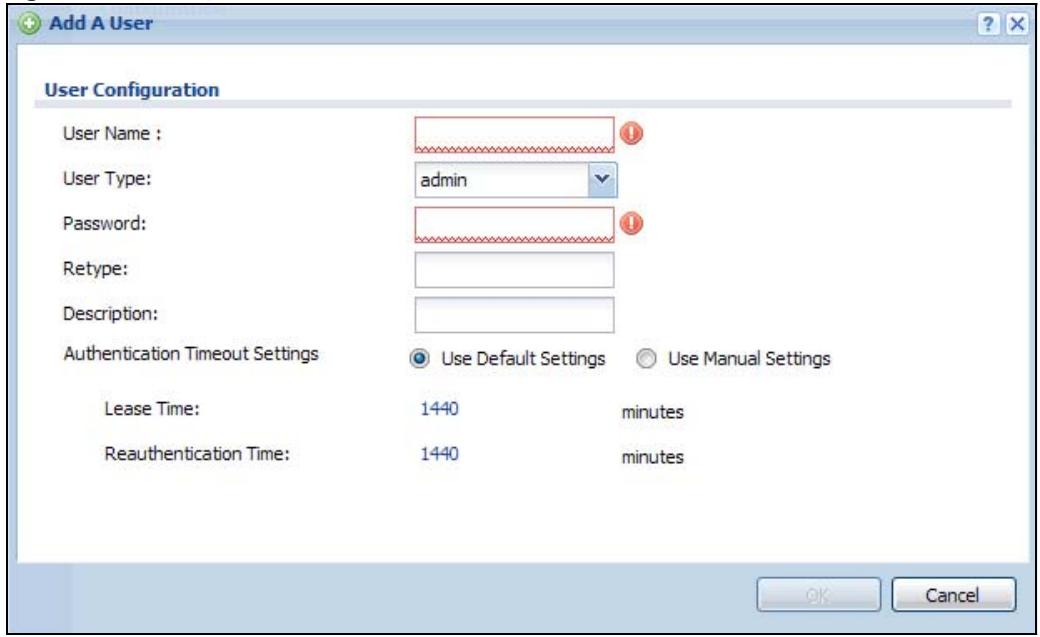
The following table describes the labels in this screen.
Table 40 Configuration > User > User > Add/Edit A User
| LABEL | DESCRIPTION |
| User Name | Type the user name for this user account. You may use 1-31 alphanumeric characters, underscores( ), or dashes (-), but the first character cannot be a number. This value is case-sensitive. User names have to be different than user group names, and some words are reserved. |
| User Type | Select what type of user this is. Choices are:admin- this user can look at and change the configuration of the NWA/WACLimited-admin- this user can look at the configuration of the NWA/WAC but not to change ituser- this is used for embedded RADIUS server and SNMPv3 user access |
| Password | Enter the password of this user account. It can consist of 4 - 63 alphanumeric characters. |
| Retype | Re-enter the password to make sure you have entered it correctly. |
| Description | Enter the description of each user, if any. You can use up to 60 printable ASCII characters. Default descriptions are provided. |
| Authentication Timeout Settings | This field is not available if the user type isuser.If you want to set authentication timeout to a value other than the default settings, selectUse Manual Settingsthen fill your preferred values in the fields that follow. |
| Lease Time | This field is not available if the user type isuser.Enter the number of minutes this user has to renew the current session before the user is logged out. You can specify 1 to 1440 minutes. You can enter 0 to make the number of minutes unlimited. Admin users renew the session every time the main screen refreshes in the Web Configurator. |
| Reauthentication Time | This field is not available if the user type isuser.Type the number of minutes this user can be logged into the NWA/WAC in one session before the user has to log in again. You can specify 1 to 1440 minutes. You can enter 0 to make the number of minutes unlimited. UnlikeLease Time, the user has no opportunity to renew the session without logging out. |
| OK | Click OKto save your changes back to the NWA/WAC. |
| Cancel | Click Cancelto exit this screen without saving your changes. |
7.3 Setting
This screen controls default settings, login settings, lockout settings, and other user settings for the NWA/WAC.
To access this screen, login to the Web Configurator, and click Configuration > Object > User > Setting.
Figure 49 Configuration > Object > User > Setting
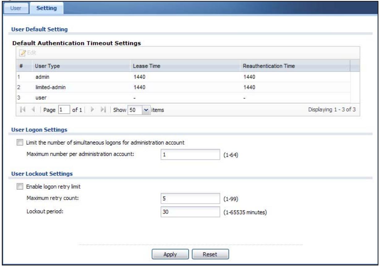
The following table describes the labels in this screen.
Table 41 Configuration > Object > User > Setting
| LABEL | DESCRIPTION |
| User Default Setting | |
| Default Authentication Timeout Settings | These authentication timeout settings are used by default when you create a new user account. They also control the settings for any existing user accounts that are set to use the default settings. You can still manually configure any user account's authentication timeout settings. |
| Edit | Double-click an entry or select it and click Edit to open a screen where you can modify the entry's settings. |
| # | This field is a sequential value, and it is not associated with a specific entry. |
| User Type | These are the kinds of user account the NWA/WAC supports.admin - this user can look at and change the configuration of the NWA/WACLimited-admin - this user can look at the configuration of the NWA/WAC but not to change ituser - this is used for embedded RADIUS server and SNMPv3 user access |
| Lease Time | This is the default lease time in minutes for each type of user account. It defines the number of minutes the user has to renew the current session before the user is logged out.Admin users renew the session every time the main screen refreshes in the Web Configurator. |
| Reauthentication Time | This is the default reauthentication time in minutes for each type of user account. It defines the number of minutes the user can be logged into the NWA/WAC in one session before having to log in again. Unlike Lease Time, the user has no opportunity to renew the session without logging out. |
| User Logon Settings | |
| Limit the number of simultaneous logons for administration account | Select this check box if you want to set a limit on the number of simultaneous logins by admin users. If you do not select this, admin users can login as many times as they want at the same time using the same or different IP addresses. |
| Maximum number per administration account | This field is effective when Limit ... for administration account is checked. Type the maximum number of simultaneous logins by each admin user. |
| User Lockout Settings | |
| Enable logon retry limit | Select this check box to set a limit on the number of times each user can login unsuccessfully (for example, wrong password) before the IP address is locked out for a specified amount of time. |
| Maximum retry count | This field is effective when Enable logon retry limit is checked. Type the maximum number of times each user can login unsuccessfully before the IP address is locked out for the specified lockout period. The number must be between 1 and 99. |
| Lockout period | This field is effective when Enable logon retry limit is checked. Type the number of minutes the user must wait to try to login again, if logon retry limit is enabled and the maximum retry count is reached. This number must be between 1 and 65,535 (about 45.5 days). |
| Apply | Click Apply to save the changes. |
| Reset | Click Reset to return the screen to its last-saved settings. |
7.3.1 Edit User Authentication Timeout Settings
This screen allows you to set the default authentication timeout settings for the selected type of user account. These default authentication timeout settings also control the settings for any existing user accounts that are set to use the default settings. You can still manually configure any user account's authentication timeout settings.
To access this screen, go to the Configuration > Object > User > Setting screen, select one of the Default Authentication Timeout Settings entry and click the Edit icon.
Figure 50 User > Setting > Edit User Authentication Timeout Settings

The following table describes the labels in this screen.
Table 42 User > Setting > Edit User Authentication Timeout Settings
| LABEL | DESCRIPTION |
| User Type | This read-only field identifies the type of user account for which you are configuring the default settings.admin- this user can look at and change the configuration of the NWA/WAC.limited-admin- this user can look at the configuration of the NWA/WAC but not to change it. |
| Lease Time | Enter the number of minutes this type of user account has to renew the current session before the user is logged out. You can specify 1 to 1440 minutes. You can enter 0 to make the number of minutes unlimited.Admin users renew the session every time the main screen refreshes in the Web Configurator. Access users can renew the session by clicking theRenewbutton on their screen. If you allow access users to renew time automatically, the users can select this check box on their screen as well. In this case, the session is automatically renewed before the lease time expires. |
| Reauthentication Time | Type the number of minutes this type of user account can be logged into the NWA/WAC in one session before the user has to log in again. You can specify 1 to 1440 minutes. You can enter 0 to make the number of minutes unlimited. UnlikeLease Time, the user has no opportunity to renew the session without logging out. |
| OK | Click OKto save your changes back to the NWA/WAC. |
| Cancel | Click Cancelto exit this screen without saving your changes. |
CHAPTER 8 AP Profile
8.1 Overview
This chapter shows you how to configure preset profiles for the NWA/WAC.
8.1.1 What You Can Do in this Chapter
- The Radio screen (Section 8.2 on page 89) creates radio configurations that can be used by the APs.
- The SSID screen (Section 8.3 on page 95) configures three different types of profiles for your networked APs.
8.1.2 What You Need To Know
The following terms and concepts may help as you read this chapter.
Wireless Profiles
At the heart of all wireless AP configurations on the NWA/WAC are profiles. A profile represents a group of saved settings that you can use across any number of connected APs. You can set up the following wireless profile types:
- Radio - This profile type defines the properties of an AP's radio transmitter. You can have a maximum of 32 radio profiles on the NWA/WAC.
- SSID - This profile type defines the properties of a single wireless network signal broadcast by an AP. Each radio on a single AP can broadcast up to 8 SSIDs. You can have a maximum of 32 SSID profiles on the NWA/WAC.
- Security - This profile type defines the security settings used by a single SSID. It controls the encryption method required for a wireless client to associate itself with the SSID. You can have a maximum of 32 security profiles on the NWA/WAC.
- MAC Filtering - This profile provides an additional layer of security for an SSID, allowing you to block access or allow access to that SSID based on wireless client MAC addresses. If a client's MAC address is on the list, then it is either allowed or denied, depending on how you set up the MAC Filter profile. You can have a maximum of 32 MAC filtering profiles on the NWA/WAC.
- Layer-2 Isolation - This profile defines the MAC addresses of the devices that you want to allow the associated wireless clients to have access to when layer-2 isolation is enabled.
SSID
The SSID (Service Set IDentifier) is the name that identifies the Service Set with which a wireless station is associated. Wireless stations associating to the access point (AP) must have the same SSID. In other words, it is the name of the wireless network that clients use to connect to it.
WEP
WEP (Wired Equivalent Privacy) encryption scrambles all data packets transmitted between the AP and the wireless stations associated with it in order to keep network communications private. Both the wireless stations and the access points must use the same WEP key for data encryption and decryption.
WPA2
WPA2 (IEEE 802.11i) is a wireless security standard that defines stronger encryption, authentication and key management than WPA. Key differences between WPA2 and WEP are improved data encryption and user authentication.
IEEE 802.1x
The IEEE 802.1x standard outlines enhanced security methods for both the authentication of wireless stations and encryption key management. Authentication is done using an external RADIUS server.
8.2 Radio
This screen allows you to create radio profiles for the NWA/WAC. A radio profile is a list of settings that an NWA/WAC can use to configure its radio transmitter(s). To access this screen click Configuration > Object > AP Profile.
Note: You can have a maximum of 32 radio profiles on the NWA/WAC.
Figure 51 Configuration > Object > AP Profile > Radio
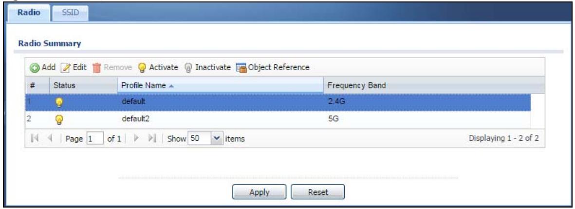
The following table describes the labels in this screen.
Table 43 Configuration > Object > AP Profile > Radio
| LABEL | DESCRIPTION |
| Add | Click this to add a new radio profile. |
| Edit | Click this to edit the selected radio profile. |
| Remove | Click this to remove the selected radio profile. |
| Activate | To turn on an entry, select it and click Activate. |
| Inactivate | To turn off an entry, select it and click Inactivate. |
| Object Reference | Click this to view which other objects are linked to the selected radio profile. |
| # | This field is a sequential value, and it is not associated with a specific user. |
| Status | This field shows whether or not the entry is activated.A yellow bulb signifies that this rule is active. A gray bulb signifies that this rule is not active. |
| Profile Name | This field indicates the name assigned to the radio profile. |
| Frequency Band | This field indicates the frequency band which this radio profile is configured to use. |
| Apply | Click Apply to save your changes back to the NWA/WAC. |
| Reset | Click Reset to return the screen to its last-saved settings. |
8.2.1 Add/Edit Radio Profile
This screen allows you to create a new radio profile or edit an existing one. To access this screen, click the Add button or select a radio profile from the list and click the Edit button.
Figure 52 Configuration > Object > AP Profile > Add/Edit Profile
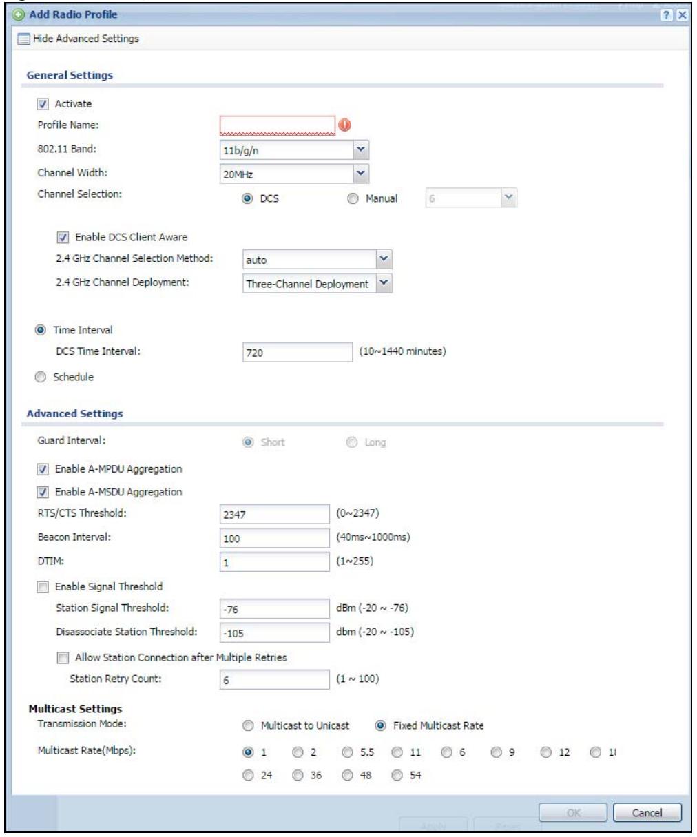
The following table describes the labels in this screen.
Table 44 Configuration > Object > AP Profile > Add/Edit Profile
| LABEL | DESCRIPTION |
| Hide / Show Advanced Settings | Click this to hide or show the Advanced Settings in this window. |
| General Settings | |
| Activate | Select this option to make this profile active. |
| Profile Name | Enter up to 31 alphanumeric characters to be used as this profile's name. Spaces and underscores are allowed. |
| 802.11 Band | Select the wireless band which this radio profile should use. Not all NWA/WACs support both 2.4 GHz and 5 GHz frequency bands.2.4 GHz is the frequency used by IEEE 802.11b/g/n wireless clients.5 GHz is the frequency used by IEEE 802.11ac/a/n wireless clients.11b/g: allows either IEEE 802.11b or IEEE 802.11g compliant WLAN devices to associate with the NWA/WAC. The NWA/WAC adjusts the transmission rate automatically according to the wireless standard supported by the wireless devices.11b/g/n: allows IEEE802.11b, IEEE802.11g and IEEE802.11n compliant WLAN devices to associate with the NWA/WAC. The transmission rate of your NWA/WAC might be reduced.11a: allows only IEEE 802.11a compliant WLAN devices to associate with the NWA/WAC.11a/n: allows both IEEE802.11n and IEEE802.11a compliant WLAN devices to associate with the NWA/WAC. The transmission rate of your NWA/WAC might be reduced.11ac: allows IEEE 802.11ac compliant WLAN devices to associate with the WAC. |
| Channel Width | Select the channel bandwidth you want to use for your wireless network.Select 20 MHz if you want to lessen radio interference with other wireless devices in your neighborhood.Select 20/40 MHz to allow the NWA/WAC to choose the channel bandwidth (20 or 40 MHz) that has least interference.Select 20/40/80 MHz to allow the NWA/WAC to choose the channel bandwidth (20 or 40 or 80 MHz) that has least interference. This option is available only when you select 11ac in the 802.11 Band field. |
| Channel Selection | This is the radio channel which the signal will use for broadcasting by this radio profile.DCS: Choose Dynamic Channel Selection to have the NWA/WAC choose a radio channel that has least interference.Manual: Choose from the available radio channels in the list. If your NWA/WAC is outdoor type, be sure to choose non-indoors channels. |
| Enable DCS Client Aware | Select this to have the AP wait until all connected clients have disconnected before switching channels.If you disable this then the AP switches channels immediately regardless of any client connections. In this instance, clients that are connected to the AP when it switches channels are dropped. |
| 2.4 GHz Channel Selection Method | Select how you want to specify the channels the NWA/WAC switches between for 2.4 GHz operation. This field appears only when you choose 802.11b/g/n mode.Select auto to have the NWA/WAC display a 2.4 GHz Channel Deployment field you can use to limit channel switching to 3 or 4 channels.Select manual to select the individual channels the NWA/WAC switches between.Note: The method is automatically set to auto when no channel is selected or any one of the previously selected channels is not supported. |
| Channel ID | This field is available only when you set Channel Selection to DCS and set 2.4 GHz Channel Selection Method to manual.Select the check boxes of the channels that you want the NWA/WAC to use. |
| 2.4 GHz Channel Deployment | This is available when the 2.4 GHz Channel Selection Method is set to auto.Select Three-Channel Deployment to limit channel switching to channels 1,6, and 11, the three channels that are sufficiently attenuated to have almost no impact on one another. In other words, this allows you to minimize channel interference by limiting channel-hopping to these three “safe” channels.Select Four-Channel Deployment to limit channel switching to four channels. Depending on the country domain, if the only allowable channels are 1-11 then the NWA/WAC uses channels 1, 4, 7, 11 in this configuration; otherwise, the NWA/WAC uses channels 1, 5, 9, 13 in this configuration. Four channel deployment expands your pool of possible channels while keeping the channel interference to a minimum. |
| Enable 5 GHz DFS Aware | This field is available only when you select 11a, 11a/n or 11ac in the 802.11 Band field and set 5 GHz Channel Selection Method to auto.Select this if your APs are operating in an area known to have RADAR devices. This allows the device to downgrade its frequency to below 5 GHz in the event RADAR signal is detected, thus preventing it from interfering with that signal.Enabling this forces the AP to select a non-DFS channel. |
| 5 GHz Channel Selection Method | Select how you want to specify the channels the NWA/WAC switches between for 5 GHz operation.Select Auto to have the NWA/WAC automatically select the best channel.Select manual to select the individual channels the NWA/WAC switches between.Note: The method is automatically set to auto when no channel is selected or any one of the previously selected channels is not supported. |
| Channel ID | This field is available only when you set Channel Selection to DCS and set 5 GHz Channel Selection Method to manual.Select the check boxes of the channels that you want the NWA/WAC to use. |
| Time Interval | Select this option to have the NWA/WAC survey the other APs within its broadcast radius at the end of the specified time interval. |
| DCS Time Interval | This field is available when you set Channel Selection to DCS and select the Time Interval option.Enter a number of minutes. This regulates how often the NWA/WAC surveys the other APs within its broadcast radius. If the channel on which it is currently broadcasting suddenly comes into use by another AP, the NWA/WAC will then dynamically select the next available clean channel or a channel with lower interference. |
| Schedule | Select this option to have the NWA/WAC survey the other APs within its broadcast radius at a specific time on selected days of the week. |
| Start Time | Specify the time of the day (in 24-hour format) to have the NWA/WAC use DCS to automatically scan and find a less-used channel. |
| Week Days | Select each day of the week to have the NWA/WAC use DCS to automatically scan and find a less-used channel. |
| Advanced Settings | |
| Guard Interval | Set the guard interval for this radio profile to either short or long. This option isn't applicable if you set 802.11 Band to 11a or 11b/g and/or choose 20 MHz channel width.The guard interval is the gap introduced between data transmission from users in order to reduce interference. Reducing the interval increases data transfer rates but also increases interference. Increasing the interval reduces data transfer rates but also reduces interference. |
| Enable A-MPDU Aggregation | Select this to enable A-MPDU aggregation. This field is not available if you set 802.11 Band to 11a or 11b/g.Message Protocol Data Unit (MPDU) aggregation collects Ethernet frames along with their 802.11n headers and wraps them in a 802.11n MAC header. This method is useful for increasing bandwidth throughput in environments that are prone to high error rates. |
| Enable A-MSDU Aggregation | Select this to enable A-MSDU aggregation. This field is not available if you set 802.11 Band to 11a or 11b/g.Mac Service Data Unit (MSDU) aggregation collects Ethernet frames without any of their 802.11n headers and wraps the header-less payload in a single 802.11n MAC header. This method is useful for increasing bandwidth throughput. It is also more efficient than A-MPDU except in environments that are prone to high error rates. |
| RTS/CTS Threshold | Use RTS/CTS to reduce data collisions on the wireless network if you have wireless clients that are associated with the same AP but out of range of one another. When enabled, a wireless client sends an RTS (Request To Send) and then waits for a CTS (Clear To Send) before it transmits. This stops wireless clients from transmitting packets at the same time (and causing data collisions).A wireless client sends an RTS for all packets larger than the number (of bytes) that you enter here. Set the RTS/CTS equal to or higher than the fragmentation threshold to turn RTS/CTS off. |
| Beacon Interval | When a wirelessly networked device sends a beacon, it includes with it a beacon interval. This specifies the time period before the device sends the beacon again. The interval tells receiving devices on the network how long they can wait in low-power mode before waking up to handle the beacon. A high value helps save current consumption of the access point. |
| DTIM | Delivery Traffic Indication Message (DTIM) is the time period after which broadcast and multicast packets are transmitted to mobile clients in the Active Power Management mode. A high DTIM value can cause clients to lose connectivity with the network. This value can be set from 1 to 255. |
| Enable Signal Threshold | Select the check box to use the signal threshold to ensure wireless clients receive good throughput. This allows only wireless clients with a strong signal to connect to the AP.Clear the check box to not require wireless clients to have a minimum signal strength to connect to the AP. |
| Station Signal Threshold | Set a minimum client signal strength. A wireless client is allowed to connect to the AP only when its signal strength is stronger than the specified threshold.-20 dBm is the strongest signal you can require and -76 is the weakest. |
| Disassociate Station Threshold | Set a minimum kick-off signal strength. When a wireless client's signal strength is lower than the specified threshold, the NWA/WAC disconnects the wireless client from the AP.-20 dBm is the strongest signal you can require and -90 is the weakest. |
| Allow Station Connection after Multiple Retries | Select this option to allow a wireless client to try to associate with the AP again after it is disconnected due to weak signal strength. |
| Station Retry Count | Set the maximum number of times a wireless client can attempt to re-connect to the AP |
| Multicast Settings | |
| Transmission Mode | Specify how the NWA/WAC handles wireless multicast traffic.Select Multicast to Unicast to broadcast wireless multicast traffic to all of the wireless clients as unicast traffic. Unicast traffic dynamically changes the data rate based on the application's bandwidth requirements. The retransmit mechanism of unicast traffic provides more reliable transmission of the multicast traffic, although it also produces duplicate packets.Select Fixed Multicast Rate to send multicast traffic to all wireless clients at a single data rate. You must know the multicast application's bandwidth requirements and set it in the following field. |
| Multicast Rate(Mbps) | If you set Transmission Mode to Fixed Multicast Rate, select a data rate at which the NWA/WAC transmits multicast packets to wireless clients. For example, to deploy 4 Mbps video, select a fixed multicast rate higher than 4 Mbps. |
| OK | Click OK to save your changes back to the NWA/WAC. |
| Cancel | Click Cancel to exit this screen without saving your changes. |
8.3 SSID
The SSID screens allow you to configure three different types of profiles for your networked APs: an SSID list, which can assign specific SSID configurations to your APs; a security list, which can assign specific encryption methods to the APs when allowing wireless clients to connect to them; and a MAC filter list, which can limit connections to an AP based on wireless clients MAC addresses.
8.3.1 SSID List
This screen allows you to create and manage SSID configurations that can be used by the APs. An SSID, or Service Set IDentifier, is basically the name of the wireless network to which a wireless client can connect. The SSID appears as readable text to any device capable of scanning for wireless frequencies (such as the WiFi adapter in a laptop), and is displayed as the wireless network name when a person makes a connection to it.
To access this screen click Configuration > Object > AP Profile > SSID.
Note: You can have a maximum of 32 SSID profiles on the NWA/WAC.
Figure 53 Configuration > Object > AP Profile > SSID List
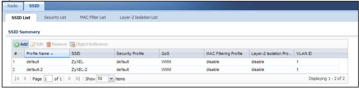
The following table describes the labels in this screen.
Table 45 Configuration > Object > AP Profile > SSID List
| LABEL | DESCRIPTION |
| Add | Click this to add a new SSID profile. |
| Edit | Click this to edit the selected SSID profile. |
| Remove | Click this to remove the selected SSID profile. |
| Object Reference | Click this to view which other objects are linked to the selected SSID profile (for example, radio profile). |
| # | This field is a sequential value, and it is not associated with a specific user. |
| Profile Name | This field indicates the name assigned to the SSID profile. |
| SSID | This field indicates the SSID name as it appears to wireless clients. |
| Security Profile | This field indicates which (if any) security profile is associated with the SSID profile. |
| QOS | This field indicates the QoS type associated with the SSID profile. |
| MAC Filtering Profile | This field indicates which (if any) MAC filter Profile is associated with the SSID profile. |
| Layer-2 Isolation Profile | This field indicates which (if any) layer-2 isolation Profile is associated with the SSID profile. |
| VLAN ID | This field indicates the VLAN ID associated with the SSID profile. |
8.3.2 Add/Edit SSID Profile
This screen allows you to create a new SSID profile or edit an existing one. To access this screen, click the Add button or select a SSID profile from the list and click the Edit button.
Figure 54 Configuration > Object > AP Profile > Add/Edit SSID Profile
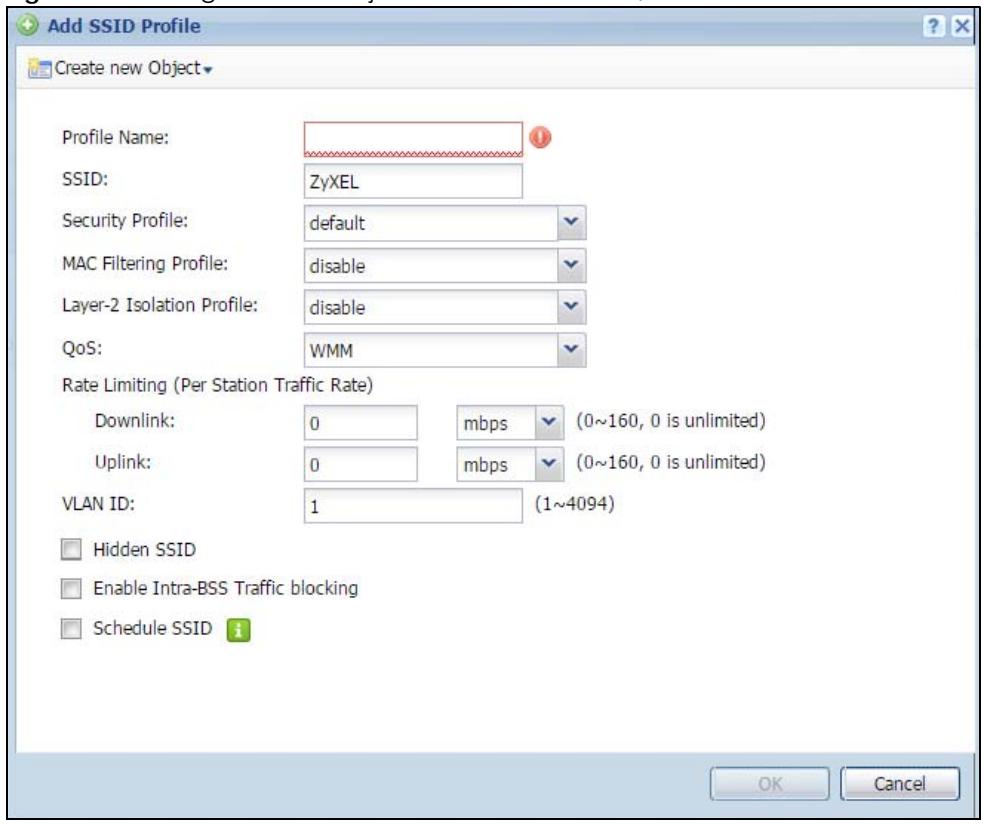
The following table describes the labels in this screen.
Table 46 Configuration > Object > AP Profile > Add/Edit SSID Profile
| LABEL | DESCRIPTION |
| Create new Object | Select an object type from the list to create a new one associated with this SSID profile. |
| Profile Name | Enter up to 31 alphanumeric characters for the profile name. This name is only visible in the Web Configurator and is only for management purposes. Spaces and underscores are allowed. |
| SSID | Enter the SSID name for this profile. This is the name visible on the network to wireless clients. Enter up to 32 characters, spaces and underscores are allowed. |
| Security Profile | Select a security profile from this list to associate with this SSID. If none exist, you can use the Create new Object menu to create one.Note: It is highly recommended that you create security profiles for all of your SSIDs to enhance your network security. |
| MAC Filtering Profile | Select a MAC filtering profile from the list to associate with this SSID. If none exist, you can use the Create new Object menu to create one.MAC filtering allows you to limit the wireless clients connecting to your network through a particular SSID by wireless client MAC addresses. Any clients that have MAC addresses not in the MAC filtering profile of allowed addresses are denied connections.The disable setting means no MAC filtering is used. |
| Layer-2 Isolation Profile | Select a layer-2 isolation profile from the list to associate with this SSID. If none exist, you can use the Create new Object menu to create one.Layer-2 isolation allows you to prevent wireless clients associated with your NWA/WAC from communicating with other wireless clients, APs, computers or routers in a network.The disable setting means no layer-2 isolation is used. |
| QoS | Select a Quality of Service (QoS) access category to associate with this SSID. Access categories minimize the delay of data packets across a wireless network. Certain categories, such as video or voice, are given a higher priority due to the time sensitive nature of their data packets.QoS access categories are as follows:disable: Turns off QoS for this SSID. All data packets are treated equally and not tagged with access categories.WMM: Enables automatic tagging of data packets. The NWA/WAC assigns access categories to the SSID by examining data as it passes through it and making a best guess effort. If something looks like video traffic, for instance, it is tagged as such.WMM_VOICE: All wireless traffic to the SSID is tagged as voice data. This is recommended if an SSID is used for activities like placing and receiving VoIP phone calls.WMM_VIDEO: All wireless traffic to the SSID is tagged as video data. This is recommended for activities like video conferencing.WMM_BEST_EFFORT: All wireless traffic to the SSID is tagged as “best effort,” meaning the data travels the best route it can without displacing higher priority traffic. This is good for activities that do not require the best bandwidth throughput, such as surfing the Internet.WMM_BACKGROUND: All wireless traffic to the SSID is tagged as low priority or “background traffic”, meaning all other access categories take precedence over this one. If traffic from an SSID does not have strict throughput requirements, then this access category is recommended. For example, an SSID that only has network printers connected to it. |
| Rate Limiting | |
| Downlink | Define the maximum incoming transmission data rate (either in mbps or kbps) on a perstation basis. |
| Uplink | Define the maximum outgoing transmission data rate (either in mbps or kbps) on a perstation basis. |
| VLAN ID | Enter a VLAN ID for the NWA/WAC to use to tag traffic originating from this SSID. |
| Hidden SSID | Select this if you want to “hide” your SSID from wireless clients. This tells any wireless clients in the vicinity of the AP using this SSID profile not to display its SSID name as a potential connection. Not all wireless clients respect this flag and display it anyway.When a SSID is “hidden” and a wireless client cannot see it, the only way you can connect to the SSID is by manually entering the SSID name in your wireless connection setup screen(s) (these vary by client, client connectivity software, and operating system). |
| Enable Intra-BSS Traffic Blocking | Select this option to prevent crossover traffic from within the same SSID on the NWA/WAC. |
| Schedule SSID | Select this option and set whether the SSID is enabled or disabled on each day of the week. You also need to select the hour and minute (in 24-hour format) to specify the time period of each day during which the SSID is enabled/enabled. |
| OK | Click OK to save your changes back to the NWA/WAC. |
| Cancel | Click Cancel to exit this screen without saving your changes. |
8.4 Security List
This screen allows you to manage wireless security configurations that can be used by your SSIDs. Wireless security is implemented strictly between the AP broadcasting the SSID and the stations that are connected to it.
To access this screen click Configuration > Object > AP Profile > SSID > Security List.
Note: You can have a maximum of 32 security profiles on the NWA/WAC.
Figure 55 Configuration > Object > AP Profile > SSID > Security List
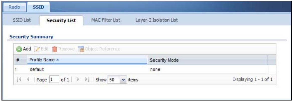
The following table describes the labels in this screen.
Table 47 Configuration > Object > AP Profile > SSID > Security List
| LABEL | DESCRIPTION |
| Add | Click this to add a new security profile. |
| Edit | Click this to edit the selected security profile. |
| Remove | Click this to remove the selected security profile. |
| Object Reference | Click this to view which other objects are linked to the selected security profile (for example, SSID profile). |
| # | This field is a sequential value, and it is not associated with a specific user. |
| Profile Name | This field indicates the name assigned to the security profile. |
| Security Mode | This field indicates this profile's security mode (if any). |
8.4.1 Add/Edit Security Profile
This screen allows you to create a new security profile or edit an existing one. To access this screen, click the Add button or select a security profile from the list and click the Edit button.
Note: This screen's options change based on the Security Mode selected. Only the default screen is displayed here.
Figure 56 Configuration > Object > AP Profile > SSID > Security List > Add/Edit Security Profile
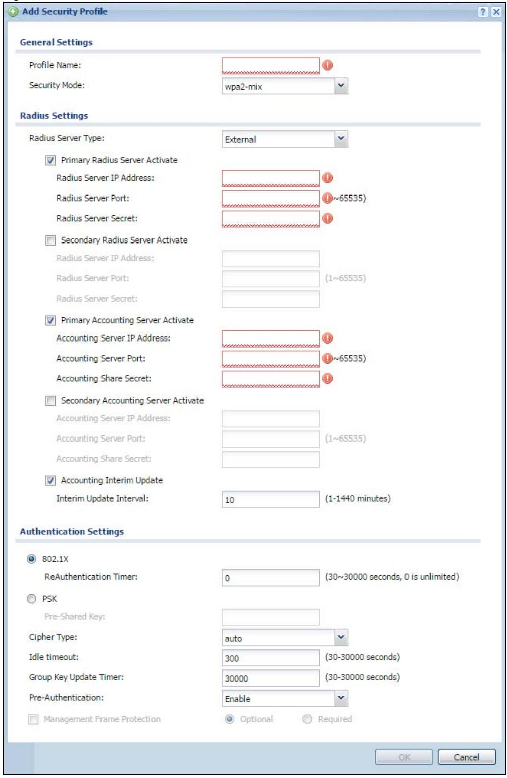
The following table describes the labels in this screen.
Table 48 Configuration > Object > AP Profile > SSID > Security List > Add/Edit Security Profile
| LABEL | DESCRIPTION |
| Profile Name | Enter up to 31 alphanumeric characters for the profile name. This name is only visible in the Web Configurator and is only for management purposes. Spaces and underscores are allowed. |
| Security Mode | Select a security mode from the list: none, wep, wpa2, or wpa2-mix. |
| Radius Server Type | This shows External and the NWA/WAC uses an external RADIUS server for authentication. |
| Primary / Secondary Radius Server Activate | Select this to have the NWA/WAC use the specified RADIUS server. |
| Radius Server IP Address | Enter the IP address of the RADIUS server to be used for authentication. |
| Radius Server Port | Enter the port number of the RADIUS server to be used for authentication. |
| Radius Server Secret | Enter the shared secret password of the RADIUS server to be used for authentication. |
| Primary / Secondary Accounting Server Activate | Select the check box to enable user accounting through an external authentication server. |
| Accounting Server IP Address | Enter the IP address of the external accounting server in dotted decimal notation. |
| Accounting Server Port | Enter the port number of the external accounting server. The default port number is 1813. You need not change this value unless your network administrator instructs you to do so with additional information. |
| Accounting Share Secret | Enter a password (up to 128 alphanumeric characters) as the key to be shared between the external accounting server and the NWA/WAC. The key must be the same on the external accounting server and your NWA/WAC. The key is not sent over the network. |
| Accounting Interim Update | This field is available only when you enable user accounting through an external authentication server.Select this to have the NWA/WAC send subscriber status updates to the accounting server at the interval you specify. |
| Interim Update Interval | Specify the time interval for how often the NWA/WAC is to send a subscriber status update to the accounting server. |
| 802.1X | Select this to enable 802.1x secure authentication. |
| ReAuthentication Timer | Enter the interval (in seconds) between authentication requests. Enter a 0 for unlimited requests. |
| WEP Authentication Settings | |
| Idle Timeout | Enter the idle interval (in seconds) that a client can be idle before authentication is discontinued. |
| Authentication Type | Select a WEP authentication method. Choices are Open or Share key. Share key is only available if you are not using 802.1x. |
| Key Length | Select the bit-length of the encryption key to be used in WEP connections.If you select WEP-64:Enter 10 hexadecimal digits in the range of “A-F”, “a-f” and “0-9” (for example, 0x11AA22BB33) for each Key used.orEnter 5 ASCII characters (case sensitive) ranging from “a-z”, “A-Z” and “0-9” (for example, MyKey) for each Key used.If you select WEP-128:Enter 26 hexadecimal digits in the range of “A-F”, “a-f” and “0-9” (for example, 0x00112233445566778899AABBCC) for each Key used.orEnter 13 ASCII characters (case sensitive) ranging from “a-z”, “A-Z” and “0-9” (for example, MyKey12345678) for each Key used. |
| Key 1~4 | Based on your Key Length selection, enter the appropriate length hexadecimal or ASCII key. |
| WPA2/WPA2-Mix Authentication Settings | |
| PSK | This field is available when you select the wpa2, or wpa2-mix security mode.Select this option to use a Pre-Shared Key with WPA2 encryption. |
| Pre-Shared Key | Enter a pre-shared key of between 8 and 63 case-sensitive ASCII characters (including spaces and symbols) or 64 hexadecimal characters. |
| Cipher Type | Select an encryption cipher type from the list.auto - This automatically chooses the best available cipher based on the cipher in use by the wireless client that is attempting to make a connection.aes - This is the Advanced Encryption Standard encryption method. It is a more recent development over TKIP and considerably more robust. Not all wireless clients may support this. |
| Idle Timeout | Enter the interval (in seconds) that a client can be idle before authentication is discontinued. |
| Group Key Update Timer | Enter the interval (in seconds) at which the AP updates the group WPA2 encryption key. |
| Management Frame Protection | This field is available only when you select wpa2 in the Security Mode field and set Cipher Type to aes.Data frames in 802.11 WLANs can be encrypted and authenticated with WEP, WPA or WPA2. But 802.11 management frames, such as beacon/probe response, association request, association response, de-authentication and disassociation are always unauthenticated and unencrypted. IEEE 802.11w Protected Management Frames allows APs to use the existing security mechanisms (encryption and authentication methods defined in IEEE 802.11i WPA/WPA2) to protect management frames. This helps prevent wireless DoS attacks.Select the check box to enable management frame protection (MFP) to add security to 802.11 management frames.Select Optional if you do not require the wireless clients to support MFP. Management frames will be encrypted if the clients support MFP.Select Required and wireless clients must support MFP in order to join the NWA/WAC's wireless network. |
| OK | Click OK to save your changes back to the NWA/WAC. |
| Cancel | Click Cancel to exit this screen without saving your changes. |
8.5 MAC Filter List
This screen allows you to create and manage security configurations that can be used by your SSIDs. To access this screen click Configuration > Object > AP Profile > SSID > MAC Filter List.
Note: You can have a maximum of 32 MAC filtering profiles on the NWA/WAC.
Figure 57 Configuration > Object > AP Profile > SSID > MAC Filter List
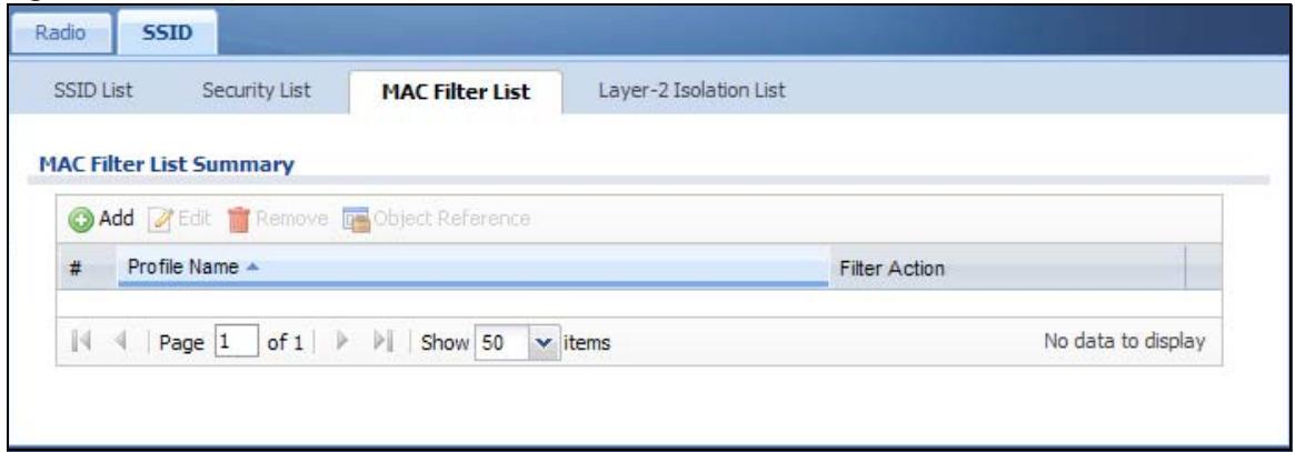
The following table describes the labels in this screen.
Table 49 Configuration > Object > AP Profile > SSID > MAC Filter List
| LABEL | DESCRIPTION |
| Add | Click this to add a new MAC filtering profile. |
| Edit | Click this to edit the selected MAC filtering profile. |
| Remove | Click this to remove the selected MAC filtering profile. |
| Object Reference | Click this to view which other objects are linked to the selected MAC filtering profile (for example, SSID profile). |
| # | This field is a sequential value, and it is not associated with a specific user. |
| Profile Name | This field indicates the name assigned to the MAC filtering profile. |
| Filter Action | This field indicates this profile's filter action (if any). |
8.5.1 Add/Edit MAC Filter Profile
This screen allows you to create a new MAC filtering profile or edit an existing one. To access this screen, click the Add button or select a MAC filter profile from the list and click the Edit button.
Note: Each MAC filtering profile can include a maximum of 512 MAC addresses.
Figure 58 Configuration > Object > AP Profile > SSID > MAC Filter List > Add/Edit MAC Filter Profile
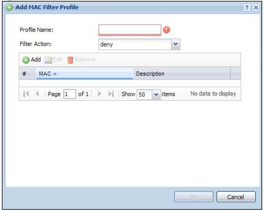
The following table describes the labels in this screen.
Table 50 Configuration > Object > AP Profile > SSID > MAC Filter List > Add/Edit MAC Filter Profile
| LABEL | DESCRIPTION |
| Profile Name | Enter up to 31 alphanumeric characters for the profile name. This name is only visible in the Web Configurator and is only for management purposes. Spaces and underscores are allowed. |
| Filter Action | Select allow to permit the wireless client with the MAC addresses in this profile to connect to the network through the associated SSID; select deny to block the wireless clients with the specified MAC addresses. |
| Add | Click this to add a MAC address to the profile's list. |
| Edit | Click this to edit the selected MAC address in the profile's list. |
| Remove | Click this to remove the selected MAC address from the profile's list. |
| # | This field is a sequential value, and it is not associated with a specific user. |
| MAC | This field specifies a MAC address associated with this profile. You can click the MAC address to make it editable. |
| Description | This field displays a description for the MAC address associated with this profile. You can click the description to make it editable. Enter up to 60 characters, spaces and underscores allowed. |
| OK | Click OK to save your changes back to the NWA/WAC. |
| Cancel | Click Cancel to exit this screen without saving your changes. |
8.6 Layer-2 Isolation List
Layer-2 isolation is used to prevent wireless clients associated with your NWA/WAC from communicating with other wireless clients, APs, computers or routers in a network.
In the following example, layer-2 isolation is enabled on the NWA/WAC to allow a guest wireless client (A) to access the main network router (B). The router provides access to the Internet and the network printer (C) while preventing the client from accessing other computers and servers on the network. The client can communicate with other wireless clients only if Intra-BSS Traffic blocking is disabled.
Note: Intra-BSS Traffic Blocking is activated when you enable layer-2 isolation.
Figure 59 Layer-2 Isolation Application
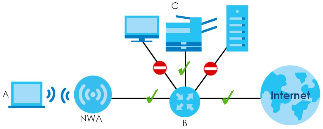
flowchart
graph TD
    A["A"] -->|Wireless Signal| NWA["NWA"]
    NWA -->|Green Checkmark| B["B"]
    B -->|Green Checkmark| C["C"]
    C --> D["Server 1"]
    C --> E["Server 2"]
    C --> F["Server 3"]
    D --> G["Internet"]
    E --> G
    F --> G
MAC addresses that are not listed in the layer-2 isolation table are blocked from communicating with the NWA/WAC's wireless clients except for broadcast packets. Layer-2 isolation does not check the traffic between wireless clients that are associated with the same AP. Intra-BSS traffic allows wireless clients associated with the same AP to communicate with each other.
This screen allows you to specify devices you want the users on your wireless networks to access. To access this screen click Configuration > Object > AP Profile > SSID > Layer-2 Isolation List.
Figure 60 Configuration > Object > AP Profile > SSID > Layer-2 Isolation List
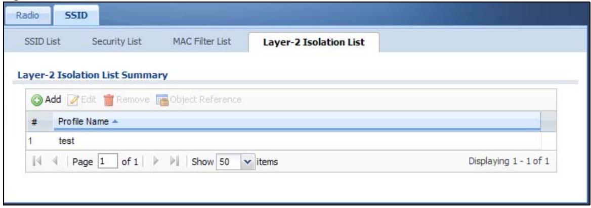
The following table describes the labels in this screen.
Table 51 Configuration > Object > AP Profile > SSID > Layer-2 Isolation List
| LABEL | DESCRIPTION |
| Add | Click this to add a new MAC filtering profile. |
| Edit | Click this to edit the selected MAC filtering profile. |
| Remove | Click this to remove the selected MAC filtering profile. |
| Object Reference | Click this to view which other objects are linked to the selected MAC filtering profile (for example, SSID profile). |
| # | This field is a sequential value, and it is not associated with a specific user. |
| Profile Name | This field indicates the name assigned to the layer-2 isolation profile. |
8.6.1 Add/Edit Layer-2 Isolation Profile
This screen allows you to create a new layer-2 isolation profile or edit an existing one. To access this screen, click the Add button or select a layer-2 isolation profile from the list and click the Edit button.
Note: You need to know the MAC address of each wireless client, AP, computer or router that you want to allow to communicate with the NWA/WAC's wireless clients.
Figure 61 Configuration > Object > AP Profile > SSID > Layer-2 Isolation List > Add/Edit Layer-2 Isolation Profile
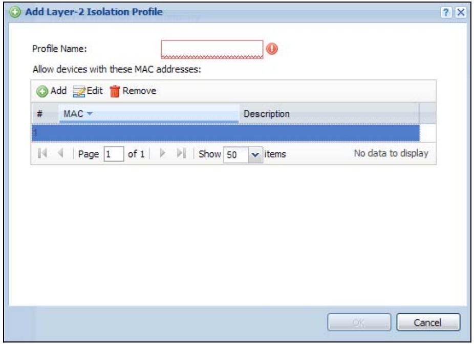
The following table describes the labels in this screen.
Table 52 Configuration > Object > AP Profile > SSID > Layer-2 Isolation List > Add/Edit Layer-2 Isolation Profile
| LABEL | DESCRIPTION |
| Profile Name | Enter up to 31 alphanumeric characters for the profile name. This name is only visible in the Web Configurator and is only for management purposes. Spaces and underscores are allowed. |
| Add | Click this to add a MAC address to the profile's list. |
| Edit | Click this to edit the selected MAC address in the profile's list. |
| Remove | Click this to remove the selected MAC address from the profile's list. |
| # | This field is a sequential value, and it is not associated with a specific user. |
| MAC | This field specifies a MAC address associated with this profile. You can click the MAC address to make it editable. |
| Description | This field displays a description for the MAC address associated with this profile. You can click the description to make it editable. Enter up to 60 characters, spaces and underscores allowed. |
| OK | Click OK to save your changes back to the NWA/WAC. |
| Cancel | Click Cancel to exit this screen without saving your changes. |
CHAPTER 9 MON Profile
9.1 Overview
This screen allows you to set up monitor mode configurations that allow your NWA/WAC to scan for other wireless devices in the vicinity. Once detected, you can use the Wireless > MON Mode screen (Section 6.3 on page 73) to classify them as either rogue or friendly.
Not all NWA/WACs support monitor mode and rogue APs detection.
9.1.1 What You Can Do in this Chapter
The MON Profile screen (Section 9.2 on page 108) creates preset monitor mode configurations that can be used by the NWA/WAC.
9.2 MON Profile
This screen allows you to create monitor mode configurations that can be used by the APs. To access this screen, login to the Web Configurator, and click Configuration > Object > MON Profile.
Figure 62 Configuration > Object > MON Profile
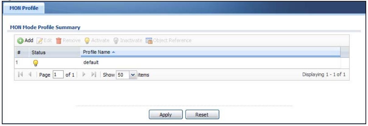
The following table describes the labels in this screen.
Table 53 Configuration > Object > MON Profile
| LABEL | DESCRIPTION |
| Add | Click this to add a new monitor mode profile. |
| Edit | Click this to edit the selected monitor mode profile. |
| Remove | Click this to remove the selected monitor mode profile. |
| Activate | To turn on an entry, select it and click Activate. |
| Inactivate | To turn off an entry, select it and click Inactivate. |
| Object Reference | Click this to view which other objects are linked to the selected monitor mode profile (for example, an AP management profile). |
| # | This field is a sequential value, and it is not associated with a specific profile. |
| Status | This field shows whether or not the entry is activated. |
| Profile Name | This field indicates the name assigned to the monitor profile. |
9.2.1 Add/Edit MON Profile
This screen allows you to create a new monitor mode profile or edit an existing one. To access this screen, click the Add button or select and existing monitor mode profile and click the Edit button.
Figure 63 Configuration > Object > MON Profile > Add/Edit MON Profile
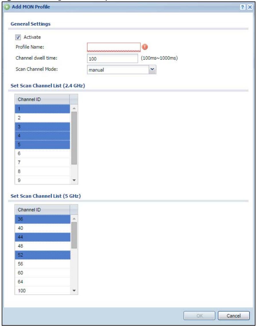
The following table describes the labels in this screen.
Table 54 Configuration > Object > MON Profile > Add/Edit MON Profile
| LABEL | DESCRIPTION |
| Activate | Select this to activate this monitor mode profile. |
| Profile Name | This field indicates the name assigned to the monitor mode profile. |
| Channel dwell time | Enter the interval (in milliseconds) before the NWA/WAC switches to another channel for monitoring. |
| Scan Channel Mode | Select auto to have the NWA/WAC switch to the next sequential channel once the Channel dwell time expires.Select manual to set specific channels through which to cycle sequentially when the Channel dwell time expires. Selecting this options makes the Scan Channel List options available. |
| Set Scan Channel List (2.4 GHz) | Select one or more than one channel to have the NWA/WAC using this profile scan the channel(s) when Scan Channel Mode is set to manual.These channels are limited to the 2.4 GHz range (802.11 b/g/n). |
| Set Scan Channel List (5 GHz) | Select one or more than one channel to have the NWA/WAC using this profile scan the channel(s) when Scan Channel Mode is set to manual.These channels are limited to the 5 GHz range (802.11 a/n). Not all NWA/WACs support both 2.4 GHz and 5 GHz frequency bands. |
| OK | Click OK to save your changes back to the NWA/WAC. |
| Cancel | Click Cancel to exit this screen without saving your changes. |
9.3 Technical Reference
The following section contains additional technical information about the features described in this chapter.
Rogue APs
Rogue APs are wireless access points operating in a network's coverage area that are not under the control of the network's administrators, and can open up holes in a network's security. Attackers can take advantage of a rogue AP's weaker (or non-existent) security to gain access to the network, or set up their own rogue APs in order to capture information from wireless clients. If a scan reveals a rogue AP, you can use commercially-available software to physically locate it.
Figure 64 Rogue AP Example
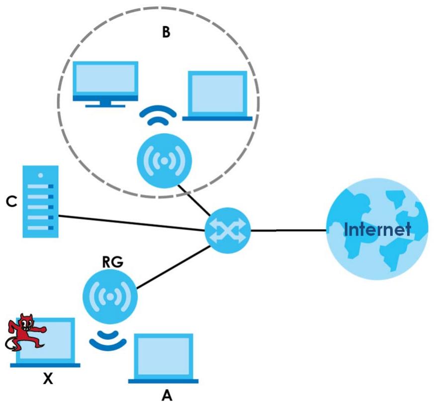
flowchart
graph TD
    A["Internet"] --> B["Server C"]
    A --> C["Server X"]
    A --> D["Server A"]
    B --> E["Central Network Node"]
    C --> E
    D --> E
    E --> F["Server B"]
    style A fill:#f9f,stroke:#333
    style B fill:#ccf,stroke:#333
    style C fill:#cfc,stroke:#333
    style D fill:#fcc,stroke:#333
    style E fill:#cff,stroke:#333
In the example above, a corporate network's security is compromised by a rogue AP (RG) set up by an employee at his workstation in order to allow him to connect his notebook computer wirelessly (A). The company's legitimate wireless network (the dashed ellipse B) is well-secured, but the rogue AP uses inferior security that is easily broken by an attacker (X) running readily available encryption-cracking software. In this example, the attacker now has access to the company network, including sensitive data stored on the file server (C).
Friendly APs
If you have more than one AP in your wireless network, you should also configure a list of “friendly” APs. Friendly APs are other wireless access points that are detected in your network, as well as any others that you know are not a threat (those from recognized networks, for example). It is recommended that you export (save) your list of friendly APs often, especially if you have a network with a large number of access points.
10.1 Overview
This chapter shows you how to configure WDS (Wireless Distribution System) profiles for the NWA/WAC to form a WDS with other APs.
10.1.1 What You Can Do in this Chapter
The WDS Profile screen (Section 10.2 on page 112) creates preset WDS configurations that can be used by the NWA/WAC.
10.2 WDS Profile
This screen allows you to manage and create WDS profiles that can be used by the APs. To access this screen, click Configuration > Object > WDS Profile.
Figure 65 Configuration > Object > WDS Profile
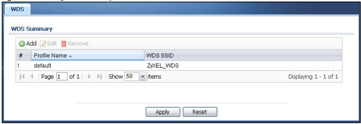
The following table describes the labels in this screen.
Table 55 Configuration > Object > WDS Profile
| LABEL | DESCRIPTION |
| Add | Click this to add a new profile. |
| Edit | Click this to edit the selected profile. |
| Remove | Click this to remove the selected profile. |
| # | This field is a sequential value, and it is not associated with a specific profile. |
| Profile Name | This field indicates the name assigned to the profile. |
| WDS SSID | This field shows the SSID specified in this WDS profile. |
10.2.1 Add/Edit WDS Profile
This screen allows you to create a new WDS profile or edit an existing one. To access this screen, click the Add button or select and existing profile and click the Edit button.
Figure 66 Configuration > Object > WDS Profile > Add/Edit WDS Profile
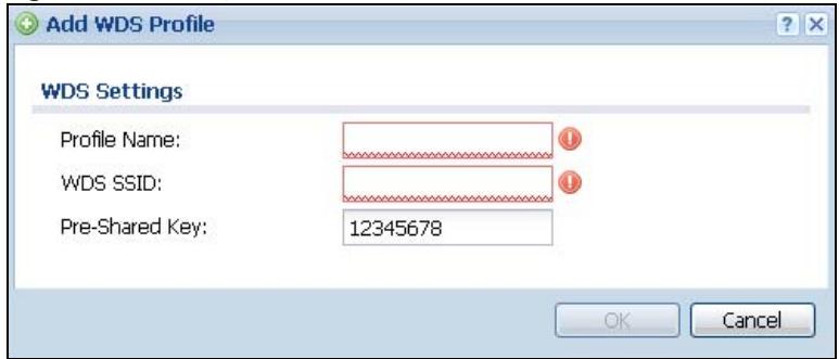
The following table describes the labels in this screen.
Table 56 Configuration > Object > WDS Profile > Add/Edit WDS Profile
| LABEL | DESCRIPTION |
| Profile Name | Enter up to 31 alphanumeric characters for the profile name. |
| WDS SSID | Enter the SSID with which you want the NWA/WAC to connect to a root AP or repeater to form a WDS. |
| Pre-Shared Key | Enter a pre-shared key of between 8 and 63 case-sensitive ASCII characters (including spaces and symbols) or 64 hexadecimal characters.The key is used to encrypt the traffic between the APs. |
| OK | Click OK to save your changes back to the NWA/WAC. |
| Cancel | Click Cancel to exit this screen without saving your changes. |
CHAPTER 11 Certificates
11.1 Overview
The NWA/WAC can use certificates (also called digital IDs) to authenticate users. Certificates are based on public-private key pairs. A certificate contains the certificate owner's identity and public key. Certificates provide a way to exchange public keys for use in authentication.
11.1.1 What You Can Do in this Chapter
- The My Certificate screens (Section 11.2 on page 117) generate and export self-signed certificates or certification requests and import the NWA/WAC's CA-signed certificates.
- The Trusted Certificates screens (Section 11.3 on page 125) save CA certificates and trusted remote host certificates to the NWA/WAC. The NWA/WAC trusts any valid certificate that you have imported as a trusted certificate. It also trusts any valid certificate signed by any of the certificates that you have imported as a trusted certificate.
11.1.2 What You Need to Know
The following terms and concepts may help as you read this chapter.
When using public-key cryptology for authentication, each host has two keys. One key is public and can be made openly available. The other key is private and must be kept secure.
These keys work like a handwritten signature (in fact, certificates are often referred to as “digital signatures”). Only you can write your signature exactly as it should look. When people know what your signature looks like, they can verify whether something was signed by you, or by someone else. In the same way, your private key “writes” your digital signature and your public key allows people to verify whether data was signed by you, or by someone else.
This process works as follows:
1 Tim wants to send a message to Jenny. He needs her to be sure that it comes from him, and that the message content has not been altered by anyone else along the way. Tim generates a public key pair (one public key and one private key).
2 Tim keeps the private key and makes the public key openly available. This means that anyone who receives a message seeming to come from Tim can read it and verify whether it is really from him or not.
3 Tim uses his private key to sign the message and sends it to Jenny.
4 Jenny receives the message and uses Tim's public key to verify it. Jenny knows that the message is from Tim, and that although other people may have been able to read the message, no-one can have altered it (because they cannot re-sign the message with Tim's private key).
5 Additionally, Jenny uses her own private key to sign a message and Tim uses Jenny's public key to verify the message.
The NWA/WAC uses certificates based on public-key cryptology to authenticate users attempting to establish a connection, not to encrypt the data that you send after establishing a connection. The method used to secure the data that you send through an established connection depends on the type of connection.
The certification authority uses its private key to sign certificates. Anyone can then use the certification authority's public key to verify the certificates.
A certification path is the hierarchy of certification authority certificates that validate a certificate. The NWA/WAC does not trust a certificate if any certificate on its path has expired or been revoked.
Certification authorities maintain directory servers with databases of valid and revoked certificates. A directory of certificates that have been revoked before the scheduled expiration is called a CRL (Certificate Revocation List). The NWA/WAC can check a peer's certificate against a directory server's list of revoked certificates. The framework of servers, software, procedures and policies that handles keys is called PKI (public-key infrastructure).
Advantages of Certificates
Certificates offer the following benefits.
- The NWA/WAC only has to store the certificates of the certification authorities that you decide to trust, no matter how many devices you need to authenticate.
- Key distribution is simple and very secure since you can freely distribute public keys and you never need to transmit private keys.
Self-signed Certificates
You can have the NWA/WAC act as a certification authority and sign its own certificates.
Factory Default Certificate
The NWA/WAC generates its own unique self-signed certificate when you first turn it on. This certificate is referred to in the GUI as the factory default certificate.
Certificate File Formats
Any certificate that you want to import has to be in one of these file formats:
- Binary X.509: This is an ITU-T recommendation that defines the formats for X.509 certificates.
- PEM (Base-64) encoded X.509: This Privacy Enhanced Mail format uses lowercase letters, uppercase letters and numerals to convert a binary X.509 certificate into a printable form.
- Binary PKCS#7: This is a standard that defines the general syntax for data (including digital signatures) that may be encrypted. A PKCS #7 file is used to transfer a public key certificate. The private key is not included. The NWA/WAC currently allows the importation of a PKS#7 file that contains a single certificate.
- PEM (Base-64) encoded PKCS#7: This Privacy Enhanced Mail (PEM) format uses lowercase letters, uppercase letters and numerals to convert a binary PKCS#7 certificate into a printable form.
- Binary PKCS#12: This is a format for transferring public key and private key certificates. The private key in a PKCS #12 file is within a password-encrypted envelope. The file's password is not connected to your certificate's public or private passwords. Exporting a PKCS #12 file creates this and you must provide it to decrypt the contents when you import the file into the NWA/WAC.
Note: Be careful not to convert a binary file to text during the transfer process. It is easy for this to occur since many programs use text files by default.
11.1.3 Verifying a Certificate
Before you import a trusted certificate into the NWA/WAC, you should verify that you have the correct certificate. You can do this using the certificate's fingerprint. A certificate's fingerprint is a message digest calculated using the MD5 or SHA1 algorithm. The following procedure describes how to check a certificate's fingerprint to verify that you have the actual certificate.
1 Browse to where you have the certificate saved on your computer.
2 Make sure that the certificate has a “.cer” or “.crt” file name extension.

3 Double-click the certificate's icon to open the Certificate window. Click the Details tab and scroll down to the Thumbprint Algorithm and Thumbprint fields.
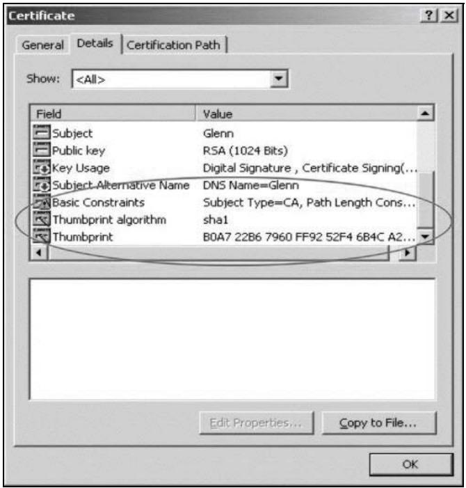
4 Use a secure method to verify that the certificate owner has the same information in the Thumbprint Algorithm and Thumbprint fields. The secure method may very based on your situation. Possible examples would be over the telephone or through an HTTPS connection.
11.2 My Certificates
Click Configuration > Object > Certificate > My Certificates to open this screen. This is the NWA/WAC's summary list of certificates and certification requests.
Figure 67 Configuration > Object > Certificate > My Certificates
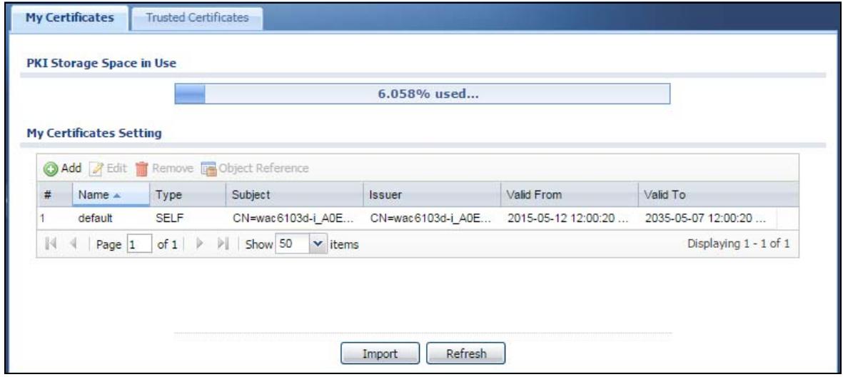
The following table describes the labels in this screen.
Table 57 Configuration > Object > Certificate > My Certificates
| LABEL | DESCRIPTION |
| PKI Storage Space in Use | This bar displays the percentage of the NWA/WAC's PKI storage space that is currently in use. When the storage space is almost full, you should consider deleting expired or unnecessary certificates before adding more certificates. |
| Add | Click this to go to the screen where you can have the NWA/WAC generate a certificate or a certification request. |
| Edit | Double-click an entry or select it and click Edit to open a screen with an in-depth list of information about the certificate. |
| Remove | The NWA/WAC keeps all of your certificates unless you specifically delete them. Uploading a new firmware or default configuration file does not delete your certificates. To remove an entry, select it and click Remove. The NWA/WAC confirms you want to remove it before doing so. Subsequent certificates move up by one when you take this action. |
| Object Reference | You cannot delete certificates that any of the NWA/WAC's features are configured to use. Select an entry and click Object Reference to open a screen that shows which settings use the entry. |
| # | This field displays the certificate index number. The certificates are listed in alphabetical order. |
| Name | This field displays the name used to identify this certificate. It is recommended that you give each certificate a unique name. |
| Type | This field displays what kind of certificate this is.REQ represents a certification request and is not yet a valid certificate. Send a certification request to a certification authority, which then issues a certificate. Use the My Certificate Import screen to import the certificate and replace the request.SELF represents a self-signed certificate.CERT represents a certificate issued by a certification authority. |
| Subject | This field displays identifying information about the certificate's owner, such as CN (Common Name), OU (Organizational Unit or department), O (Organization or company) and C (Country). It is recommended that each certificate have unique subject information. |
| Issuer | This field displays identifying information about the certificate's issuing certification authority, such as a common name, organizational unit or department, organization or company and country. With self-signed certificates, this is the same information as in the Subject field. |
| Valid From | This field displays the date that the certificate becomes applicable. |
| Valid To | This field displays the date that the certificate expires. The text displays in red and includes an Expired! message if the certificate has expired. |
| Import | Click Import to open a screen where you can save a certificate to the NWA/WAC. |
| Refresh | Click Refresh to display the current validity status of the certificates. |
11.2.1 Add My Certificates
Click Configuration > Object > Certificate > My Certificates and then the Add icon to open the Add My Certificates screen. Use this screen to have the NWA/WAC create a self-signed certificate, enroll a certificate with a certification authority or generate a certification request.
Figure 68 Configuration > Object > Certificate > My Certificates > Add
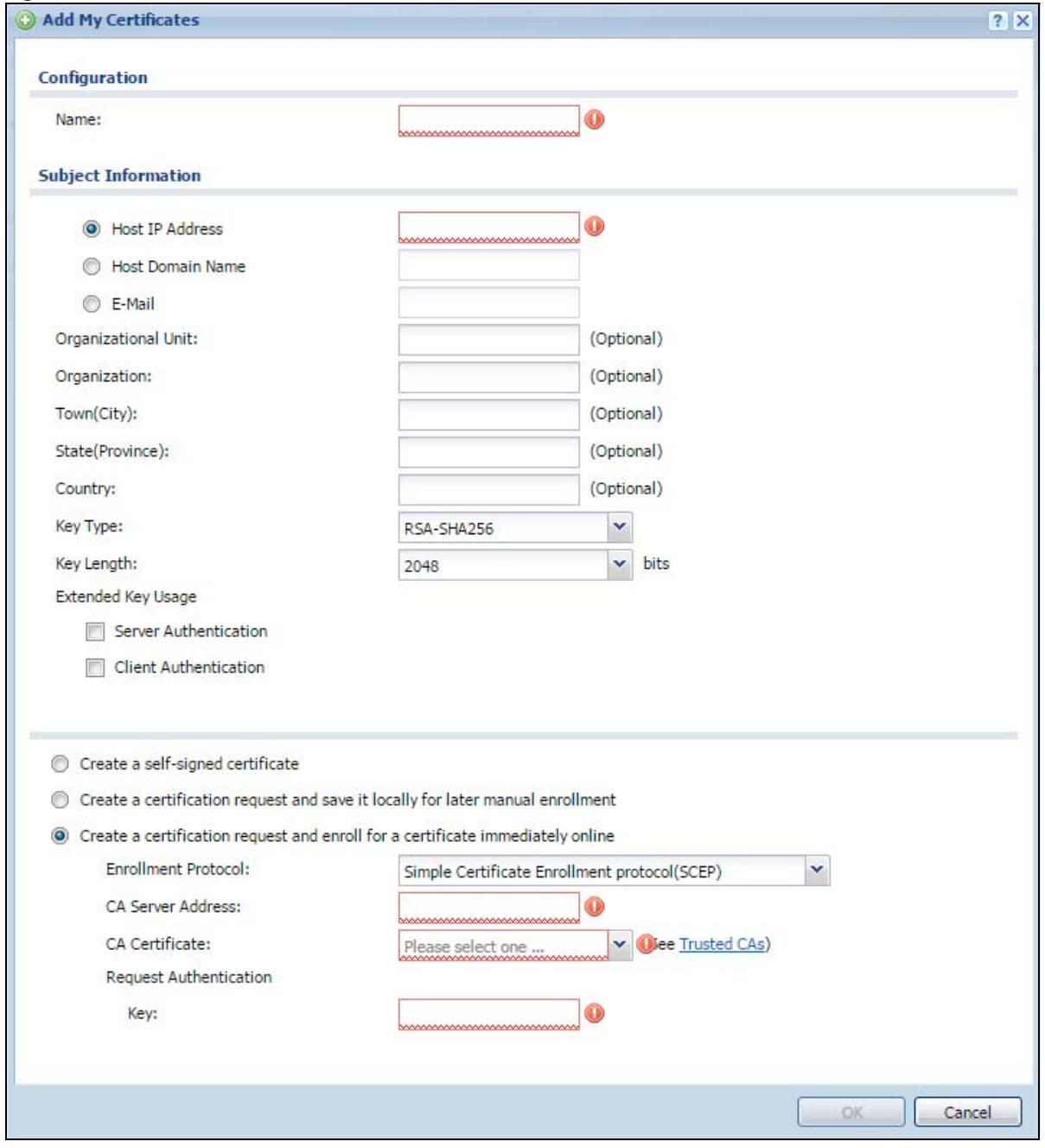
The following table describes the labels in this screen.
Table 58 Configuration > Object > Certificate > My Certificates > Add
| LABEL | DESCRIPTION |
| Name | Type a name to identify this certificate. You can use up to 31 alphanumeric and ;‘~!@#%^&()_+[]',=- characters. |
| Subject Information | Use these fields to record information that identifies the owner of the certificate. You do not have to fill in every field, although you must specify a Host IP Address, Host Domain Name, or E-Mail. The certification authority may add fields (such as a serial number) to the subject information when it issues a certificate. It is recommended that each certificate have unique subject information.Select a radio button to identify the certificate's owner by IP address, domain name or e-mail address. Type the IP address (in dotted decimal notation), domain name or e-mail address in the field provided. The domain name or e-mail address is for identification purposes only and can be any string.A domain name can be up to 255 characters. You can use alphanumeric characters, the hyphen and periods.An e-mail address can be up to 63 characters. You can use alphanumeric characters, the hyphen, the @ symbol, periods and the underscore. |
| Organizational Unit | Identify the organizational unit or department to which the certificate owner belongs. You can use up to 31 characters. You can use alphanumeric characters, the hyphen and the underscore. |
| Organization | Identify the company or group to which the certificate owner belongs. You can use up to 31 characters. You can use alphanumeric characters, the hyphen and the underscore. |
| Town (City) | Identify the town or city where the certificate owner is located. You can use up to 31 characters. You can use alphanumeric characters, the hyphen and the underscore. |
| State (Province) | Identify the state or province where the certificate owner is located. You can use up to 31 characters. You can use alphanumeric characters, the hyphen and the underscore. |
| Country | Identify the nation where the certificate owner is located. You can use up to 31 characters. You can use alphanumeric characters, the hyphen and the underscore. |
| Key Type | The NWA/WAC uses the RSA (Rivest, Shamir and Adleman) public-key encryption algorithm. SHA1 (Secure Hash Algorithm) and SHA2 are hash algorithms used to authenticate packet data. SHA2-256 or SHA2-512 are part of the SHA2 set of cryptographic functions and they are considered even more secure than SHA1.Select a key type from RSA-SHA256 and RSA-SHA512. |
| Key Length | Select a number from the drop-down list box to determine how many bits the key should use (1024 to 2048). The longer the key, the more secure it is. A longer key also uses more PKI storage space. |
| Extended Key Usage | Select Server Authentication to allow a web server to send clients the certificate to authenticate itself.Select Client Authentication to use the certificate's key to authenticate clients to the secure gateway. |
| These radio buttons deal with how and when the certificate is to be generated. | |
| Create a self-signed certificate | Select this to have the NWA/WAC generate the certificate and act as the Certification Authority (CA) itself. This way you do not need to apply to a certification authority for certificates. |
| Create a certification request and save it locally for later manual enrollment | Select this to have the NWA/WAC generate and store a request for a certificate. Use the My Certificate Edit screen to view the certification request and copy it to send to the certification authority.Copy the certification request from the My Certificate Edit screen and then send it to the certification authority. |
| Create a certification request and enroll for a certificate immediately online | Select this to have the NWA/WAC generate a request for a certificate and apply to a certification authority for a certificate.You must have the certification authority's certificate already imported in the Trusted Certificates screen.When you select this option, you must select the certification authority's enrollment protocol and the certification authority's certificate from the drop-down list boxes and enter the certification authority's server address. You also need to fill in the Reference Number and Key if the certification authority requires them. |
| Enrollment Protocol | This field applies when you select Create a certification request and enroll for a certificate immediately online. Select the certification authority's enrollment protocol from the drop-down list box.Simple Certificate Enrollment Protocol (SCEP) is a TCP-based enrollment protocol that was developed by VeriSign and Cisco.Certificate Management Protocol (CMP) is a TCP-based enrollment protocol that was developed by the Public Key Infrastructure X.509 working group of the Internet Engineering Task Force (IETF) and is specified in RFC 2510. |
| CA Server Address | This field applies when you select Create a certification request and enroll for a certificate immediately online. Enter the IP address (or URL) of the certification authority server.For a URL, you can use up to 511 of the following characters. a-zA-Z0-9'()+/:=?;!*#@%- |
| CA Certificate | This field applies when you select Create a certification request and enroll for a certificate immediately online. Select the certification authority's certificate from the CA Certificate drop-down list box.You must have the certification authority's certificate already imported in the Trusted Certificates screen. Click Trusted CAs to go to the Trusted Certificates screen where you can view (and manage) the NWA/WAC's list of certificates of trusted certification authorities. |
| Request Authentication | When you select Create a certification request and enroll for a certificate immediately online, the certification authority may want you to include a reference number and key to identify you when you send a certification request.Fill in both the Reference Number and the Key fields if your certification authority uses the CMP enrollment protocol. Just the Key field displays if your certification authority uses the SCEP enrollment protocol.For the reference number, use 0 to 99999999.For the key, use up to 31 of the following characters. a-zA-Z0-9; | `!@#$%^&*()_+\{'':./<>=- |
| OK | Click OK to begin certificate or certification request generation. |
| Cancel | Click Cancel to quit and return to the My Certificates screen. |
If you configured the Add My Certificates screen to have the NWA/WAC enroll a certificate and the certificate enrollment is not successful, you see a screen with a Return button that takes you back to the Add My Certificates screen. Click Return and check your information in the Add My Certificates screen. Make sure that the certification authority information is correct and that your Internet connection is working properly if you want the NWA/WAC to enroll a certificate online.
11.2.2 Edit My Certificates
Click Configuration > Object > Certificate > My Certificates and then the Edit icon to open the My Certificate Edit screen. You can use this screen to view in-depth certificate information and change the certificate's name.
Figure 69 Configuration > Object > Certificate > My Certificates > Edit
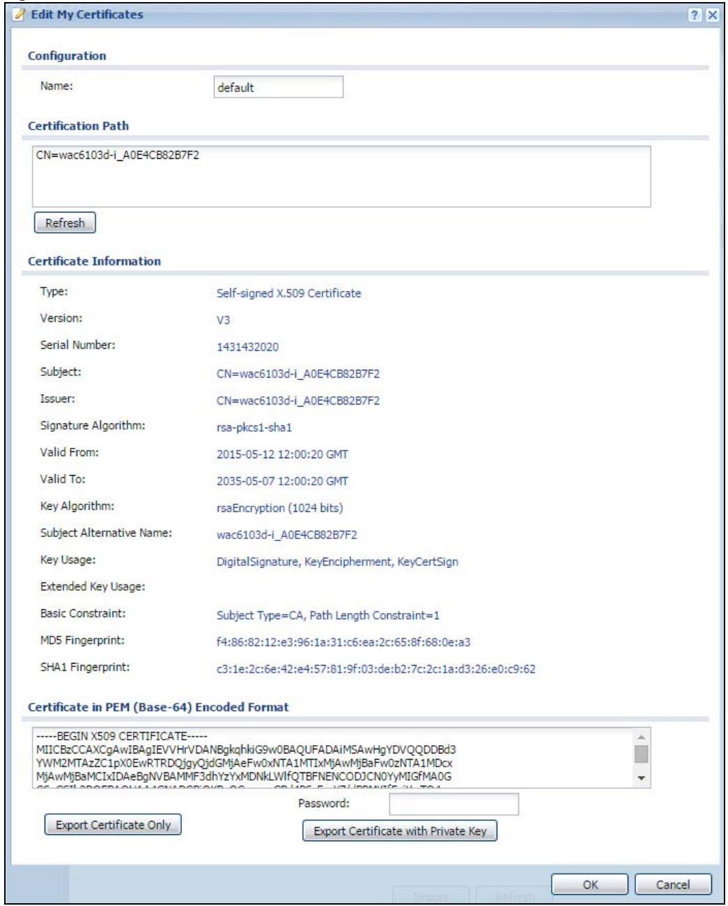
The following table describes the labels in this screen.
Table 59 Configuration > Object > Certificate > My Certificates > Edit
| LABEL | DESCRIPTION |
| Name | This field displays the identifying name of this certificate. You can use up to 31 alphanumeric and ;‘~!@#$%^&()_+[]{}',=- characters. |
| Certification Path | This field displays for a certificate, not a certification request.Click the Refresh button to have this read-only text box display the hierarchy of certification authorities that validate the certificate (and the certificate itself).If the issuing certification authority is one that you have imported as a trusted certification authority, it may be the only certification authority in the list (along with the certificate itself). If the certificate is a self-signed certificate, the certificate itself is the only one in the list. The NWA/WAC does not trust the certificate and displays “Not trusted” in this field if any certificate on the path has expired or been revoked. |
| Refresh | Click Refresh to display the certification path. |
| Certificate Information | These read-only fields display detailed information about the certificate. |
| Type | This field displays general information about the certificate. CA-signed means that a Certification Authority signed the certificate. Self-signed means that the certificate's owner signed the certificate (not a certification authority). “X.509” means that this certificate was created and signed according to the ITU-T X.509 recommendation that defines the formats for public-key certificates. |
| Version | This field displays the X.509 version number. “ |
| Serial Number | This field displays the certificate's identification number given by the certification authority or generated by the NWA/WAC. |
| Subject | This field displays information that identifies the owner of the certificate, such as Common Name (CN), Organizational Unit (OU), Organization (O), State (ST), and Country (C). |
| Issuer | This field displays identifying information about the certificate's issuing certification authority, such as Common Name, Organizational Unit, Organization and Country.With self-signed certificates, this is the same as the Subject Name field.“none” displays for a certification request. |
| Signature Algorithm | This field displays the type of algorithm that was used to sign the certificate. |
| Valid From | This field displays the date that the certificate becomes applicable. “none” displays for a certification request. |
| Valid To | This field displays the date that the certificate expires. The text displays in red and includes an Expired! message if the certificate has expired. “none” displays for a certification request. |
| Key Algorithm | This field displays the type of algorithm that was used to generate the certificate's key pair (the NWA/WAC uses RSA encryption) and the length of the key set in bits (1024 bits for example). |
| Subject Alternative Name | This field displays the certificate owner's IP address (IP), domain name (DNS) or e-mail address (EMAIL). |
| Key Usage | This field displays for what functions the certificate's key can be used. For example, “DigitalSignature” means that the key can be used to sign certificates and “KeyEncipherment” means that the key can be used to encrypt text. |
| Extended Key Usage | This field displays for what EKU (Extended Key Usage) functions the certificate's key can be used. |
| Basic Constraint | This field displays general information about the certificate. For example, Subject Type=CA means that this is a certification authority's certificate and “Path Length Constraint=1” means that there can only be one certification authority in the certificate's path. This field does not display for a certification request. |
Table 59 Configuration > Object > Certificate > My Certificates > Edit
| LABEL | DESCRIPTION |
| MD5 Fingerprint | This is the certificate's message digest that the NWA/WAC calculated using the MD5 algorithm. |
| SHA1 Fingerprint | This is the certificate's message digest that the NWA/WAC calculated using the SHA1 algorithm. |
| Certificate in PEM (Base-64) Encoded Format | This read-only text box displays the certificate or certification request in Privacy Enhanced Mail (PEM) format. PEM uses lowercase letters, uppercase letters and numerals to convert a binary certificate into a printable form.You can copy and paste a certification request into a certification authority's web page, an e-mail that you send to the certification authority or a text editor and save the file on a management computer for later manual enrollment.You can copy and paste a certificate into an e-mail to send to friends or colleagues or you can copy and paste a certificate into a text editor and save the file on a management computer for later distribution (via floppy disk for example). |
| Export Certificate Only | Use this button to save a copy of the certificate without its private key. Click this button and then Save in the File Download screen. The Save As screen opens, browse to the location that you want to use and click Save. |
| Password | If you want to export the certificate with its private key, create a password and type it here. Make sure you keep this password in a safe place. You will need to use it if you import the certificate to another device. |
| Export Certificate with Private Key | Use this button to save a copy of the certificate with its private key. Type the certificate's password and click this button. Click Save in the File Download screen. The Save As screen opens, browse to the location that you want to use and click Save. |
| OK | Click OK to save your changes back to the NWA/WAC. You can only change the name. |
| Cancel | Click Cancel to quit and return to the My Certificates screen. |
11.2.3 Import Certificates
Click Configuration > Object > Certificate > My Certificates > Import to open the My Certificate Import screen. Follow the instructions in this screen to save an existing certificate to the NWA/WAC.
Note: You can import a certificate that matches a corresponding certification request that was generated by the NWA/WAC. You can also import a certificate in PKCS#12 format, including the certificate's public and private keys.
The certificate you import replaces the corresponding request in the My Certificates screen.
You must remove any spaces in the certificate's filename before you can import it.
Figure 70 Configuration > Object > Certificate > My Certificates > Import
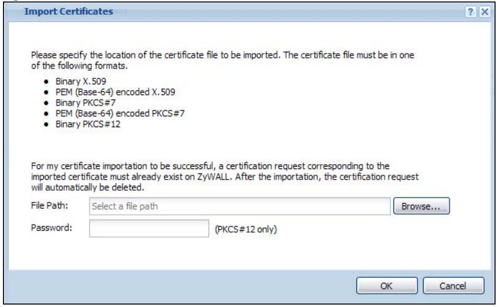
The following table describes the labels in this screen.
Table 60 Configuration > Object > Certificate > My Certificates > Import
| LABEL | DESCRIPTION |
| File Path | Type in the location of the file you want to upload in this field or clickBrowseto find it.You cannot import a certificate with the same name as a certificate that is already in the NWA/WAC. |
| Browse | ClickBrowseto find the certificate file you want to upload. |
| Password | This field only applies when you import a binary PKCS#12 format file. Type the file's password that was created when the PKCS #12 file was exported. |
| OK | ClickOKto save the certificate on the NWA/WAC. |
| Cancel | ClickCancelto quit and return to theMy Certificatesscreen. |
11.3 Trusted Certificates
Click Configuration > Object > Certificate > Trusted Certificates to open the Trusted Certificates screen. This screen displays a summary list of certificates that you have set the NWA/WAC to accept as trusted. The NWA/WAC also accepts any valid certificate signed by a certificate on this list as being trustworthy; thus you do not need to import any certificate that is signed by one of these certificates.
Figure 71 Configuration > Object > Certificate > Trusted Certificates
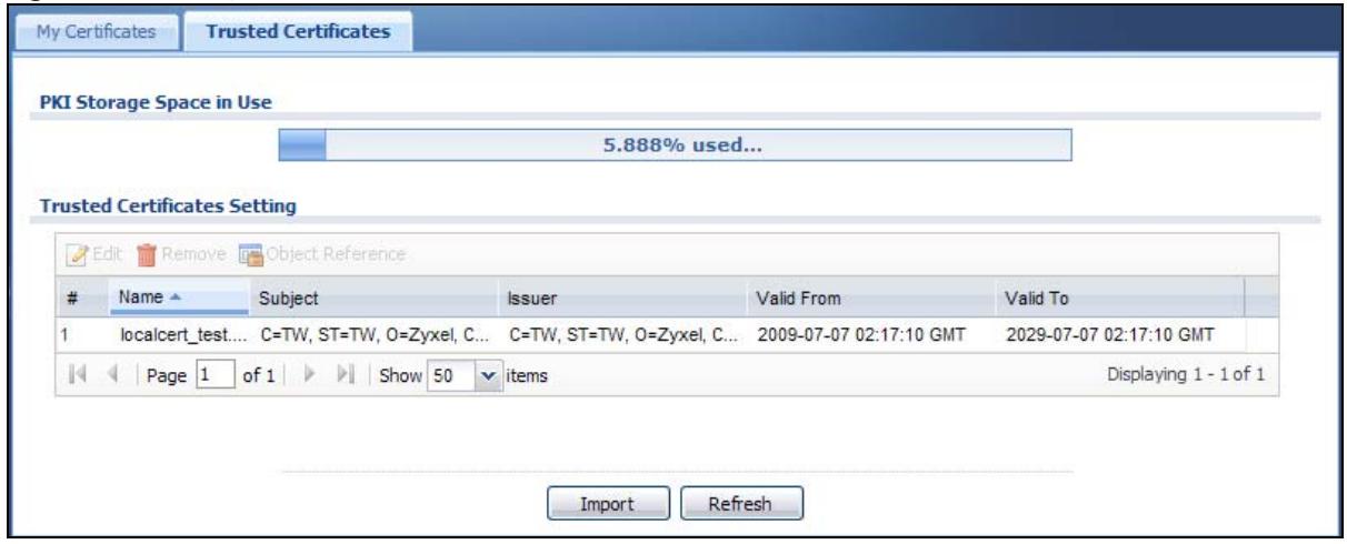
The following table describes the labels in this screen.
Table 61 Configuration > Object > Certificate > Trusted Certificates
| LABEL | DESCRIPTION |
| PKI Storage Space in Use | This bar displays the percentage of the NWA/WAC's PKI storage space that is currently in use. When the storage space is almost full, you should consider deleting expired or unnecessary certificates before adding more certificates. |
| Edit | Double-click an entry or select it and click Edit to open a screen with an in-depth list of information about the certificate. |
| Remove | The NWA/WAC keeps all of your certificates unless you specifically delete them. Uploading a new firmware or default configuration file does not delete your certificates. To remove an entry, select it and click Remove. The NWA/WAC confirms you want to remove it before doing so. Subsequent certificates move up by one when you take this action. |
| Object Reference | You cannot delete certificates that any of the NWA/WAC's features are configured to use. Select an entry and click Object Reference to open a screen that shows which settings use the entry. |
| # | This field displays the certificate index number. The certificates are listed in alphabetical order. |
| Name | This field displays the name used to identify this certificate. |
| Subject | This field displays identifying information about the certificate's owner, such as CN (Common Name), OU (Organizational Unit or department), O (Organization or company) and C (Country). It is recommended that each certificate have unique subject information. |
| Issuer | This field displays identifying information about the certificate's issuing certification authority, such as a common name, organizational unit or department, organization or company and country. With self-signed certificates, this is the same information as in the Subject field. |
| Valid From | This field displays the date that the certificate becomes applicable. |
| Valid To | This field displays the date that the certificate expires. The text displays in red and includes an Expired! message if the certificate has expired. |
| Import | Click Import to open a screen where you can save the certificate of a certification authority that you trust, from your computer to the NWA/WAC. |
| Refresh | Click this button to display the current validity status of the certificates. |
11.3.1 Edit Trusted Certificates
Click Configuration > Object > Certificate > Trusted Certificates and then a certificate's Edit icon to open the Trusted Certificates Edit screen. Use this screen to view in-depth information about the certificate,
change the certificate's name and set whether or not you want the NWA/WAC to check a certification authority's list of revoked certificates before trusting a certificate issued by the certification authority.
Figure 72 Configuration > Object > Certificate > Trusted Certificates > Edit

The following table describes the labels in this screen.
Table 62 Configuration > Object > Certificate > Trusted Certificates > Edit
| LABEL | DESCRIPTION |
| Name | This field displays the identifying name of this certificate. You can change the name. You can use up to 31 alphanumeric and ;‘~!@#$%^&()_+[]{}',=- characters. |
| Certification Path | Click the Refresh button to have this read-only text box display the end entity's certificate and a list of certification authority certificates that shows the hierarchy of certification authorities that validate the end entity's certificate. If the issuing certification authority is one that you have imported as a trusted certificate, it may be the only certification authority in the list (along with the end entity's own certificate). The NWA/WAC does not trust the end entity's certificate and displays “Not trusted” in this field if any certificate on the path has expired or been revoked. |
| Refresh | Click Refresh to display the certification path. |
| Enable X.509v3 CRL Distribution Points and OCSP checking | Select this check box to have the NWA/WAC check incoming certificates that are signed by this certificate against a Certificate Revocation List (CRL) or an OCSP server. You also need to configure the OSCP or LDAP server details. |
| OCSP Server | Select this check box if the directory server uses OCSP (Online Certificate Status Protocol). |
| URL | Type the protocol, IP address and pathname of the OCSP server. |
| ID | The NWA/WAC may need to authenticate itself in order to assess the OCSP server. Type the login name (up to 31 ASCII characters) from the entity maintaining the server (usually a certification authority). |
| Password | Type the password (up to 31 ASCII characters) from the entity maintaining the OCSP server (usually a certification authority). |
| LDAP Server | Select this check box if the directory server uses LDAP (Lightweight Directory Access Protocol). LDAP is a protocol over TCP that specifies how clients access directories of certificates and lists of revoked certificates. |
| Address | Type the IP address (in dotted decimal notation) of the directory server. |
| Port | Use this field to specify the LDAP server port number. You must use the same server port number that the directory server uses. 389 is the default server port number for LDAP. |
| ID | The NWA/WAC may need to authenticate itself in order to assess the CRL directory server. Type the login name (up to 31 ASCII characters) from the entity maintaining the server (usually a certification authority). |
| Password | Type the password (up to 31 ASCII characters) from the entity maintaining the CRL directory server (usually a certification authority). |
| Certificate Information | These read-only fields display detailed information about the certificate. |
| Type | This field displays general information about the certificate. CA-signed means that a Certification Authority signed the certificate. Self-signed means that the certificate's owner signed the certificate (not a certification authority). X.509 means that this certificate was created and signed according to the ITU-T X.509 recommendation that defines the formats for public-key certificates. |
| Version | This field displays the X.509 version number. |
| Serial Number | This field displays the certificate's identification number given by the certification authority. |
| Subject | This field displays information that identifies the owner of the certificate, such as Common Name (CN), Organizational Unit (OU), Organization (O) and Country (C). |
| Issuer | This field displays identifying information about the certificate's issuing certification authority, such as Common Name, Organizational Unit, Organization and Country.With self-signed certificates, this is the same information as in the Subject Name field. |
| Signature Algorithm | This field displays the type of algorithm that was used to sign the certificate. Some certification authorities use rsa-pkcs1-sha1 (RSA public-private key encryption algorithm and the SHA1 hash algorithm). Other certification authorities may use rsa-pkcs1-md5 (RSA public-private key encryption algorithm and the MD5 hash algorithm). |
| Valid From | This field displays the date that the certificate becomes applicable. The text displays in red and includes a Not Yet Valid! message if the certificate has not yet become applicable. |
| Valid To | This field displays the date that the certificate expires. The text displays in red and includes an Expiring! or Expired! message if the certificate is about to expire or has already expired. |
| Key Algorithm | This field displays the type of algorithm that was used to generate the certificate's key pair (the NWA/WAC uses RSA encryption) and the length of the key set in bits (1024 bits for example). |
| Subject Alternative Name | This field displays the certificate's owner's IP address (IP), domain name (DNS) or e-mail address (EMAIL). |
| Key Usage | This field displays for what functions the certificate's key can be used. For example, "DigitalSignature" means that the key can be used to sign certificates and "KeyEncipherment" means that the key can be used to encrypt text. |
| Basic Constraint | This field displays general information about the certificate. For example, Subject Type=CA means that this is a certification authority's certificate and "Path Length Constraint=1" means that there can only be one certification authority in the certificate's path. |
| MD5 Fingerprint | This is the certificate's message digest that the NWA/WAC calculated using the MD5 algorithm. You can use this value to verify with the certification authority (over the phone for example) that this is actually their certificate. |
| SHA1 Fingerprint | This is the certificate's message digest that the NWA/WAC calculated using the SHA1 algorithm. You can use this value to verify with the certification authority (over the phone for example) that this is actually their certificate. |
| Certificate | This read-only text box displays the certificate or certification request in Privacy Enhanced Mail (PEM) format. PEM uses lowercase letters, uppercase letters and numerals to convert a binary certificate into a printable form.You can copy and paste the certificate into an e-mail to send to friends or colleagues or you can copy and paste the certificate into a text editor and save the file on a management computer for later distribution (via floppy disk for example). |
| Export Certificate | Click this button and then Save in the File Download screen. The Save As screen opens, browse to the location that you want to use and click Save. |
| OK | Click OK to save your changes back to the NWA/WAC. You can only change the name. |
| Cancel | Click Cancel to quit and return to the Trusted Certificates screen. |
11.3.2 Import Trusted Certificates
Click Configuration > Object > Certificate > Trusted Certificates > Import to open the Import Trusted Certificates screen. Follow the instructions in this screen to save a trusted certificate to the NWA/WAC.
Note: You must remove any spaces from the certificate's filename before you can import the certificate.
Figure 73 Configuration > Object > Certificate > Trusted Certificates > Import
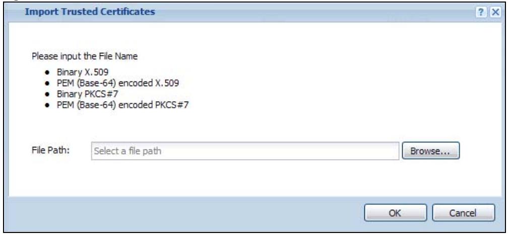
The following table describes the labels in this screen.
Table 63 Configuration > Object > Certificate > Trusted Certificates > Import
| LABEL | DESCRIPTION |
| File Path | Type in the location of the file you want to upload in this field or clickBrowseto find it.You cannot import a certificate with the same name as a certificate that is already in the NWA/WAC. |
| Browse | ClickBrowseto find the certificate file you want to upload. |
| OK | ClickOKto save the certificate on the NWA/WAC. |
| Cancel | ClickCancelto quit and return to the previous screen. |
11.4 Technical Reference
The following section contains additional technical information about the features described in this chapter.
OCSP
OCSP (Online Certificate Status Protocol) allows an application or device to check whether a certificate is valid. With OCSP the NWA/WAC checks the status of individual certificates instead of downloading a Certificate Revocation List (CRL). OCSP has two main advantages over a CRL. The first is real-time status information. The second is a reduction in network traffic since the NWA/WAC only gets information on the certificates that it needs to verify, not a huge list. When the NWA/WAC requests certificate status information, the OCSP server returns a “expired”, “current” or “unknown” response.
12.1 Overview
Use the system screens to configure general NWA/WAC settings.
12.1.1 What You Can Do in this Chapter
- The Host Name screen (Section 12.2 on page 131) configures a unique name for the NWA/WAC in your network.
- The Date/Time screen (Section 12.3 on page 132) configures the date and time for the NWA/WAC.
- The WWW screens (Section 12.4 on page 136) configure settings for HTTP or HTTPS access to the NWA/WAC.
- The SSH screen (Section 12.5 on page 146) configures SSH (Secure SHell) for securely accessing the NWA/WAC's command line interface.
- The Telnet screen (Section 12.6 on page 150) configures Telnet for accessing the NWA/WAC's command line interface.
- The FTP screen (Section 12.7 on page 150) specifies FTP server settings. You can upload and download the NWA/WAC's firmware and configuration files using FTP. Please also see Chapter 14 on page 169 for more information about firmware and configuration files.
- The SNMP screens (Section 12.8 on page 151) configure the device's SNMP settings, including profiles that define allowed SNMPv3 access.
12.2 Host Name
A host name is the unique name by which a device is known on a network. Click Configuration > System > Host Name to open this screen.
Figure 74 Configuration > System > Host Name
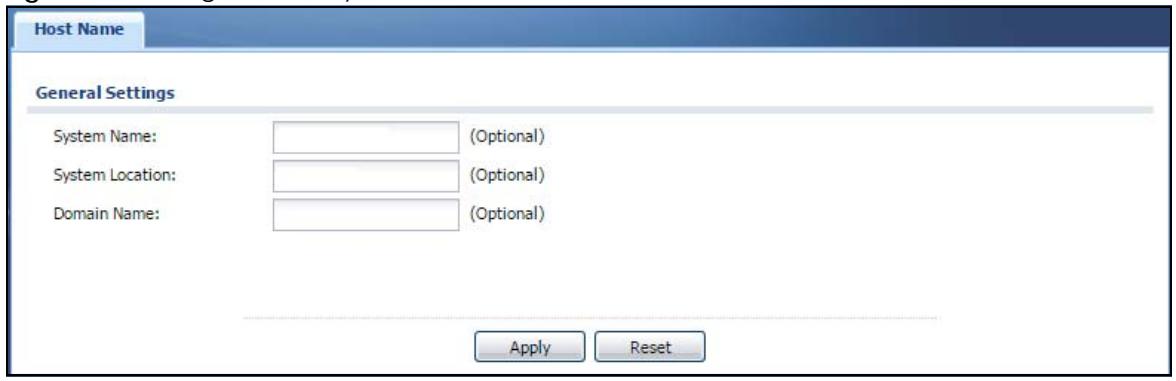
The following table describes the labels in this screen.
Table 64 Configuration > System > Host Name
| LABEL | DESCRIPTION |
| System Name | Choose a descriptive name to identify your NWA/WAC device. This name can be up to 64 alphanumeric characters long. Spaces are not allowed, but dashes (-) underscores (_) and periods (.) are accepted. |
| System Location | Specify the name of the place where the NWA/WAC is located. You can enter up to 60 alphanumeric and '(')',;?! +-*/*= #$%@ characters. Spaces and underscores are allowed. The name should start with a letter. |
| Domain Name | Enter the domain name (if you know it) here. This name is propagated to DHCP clients connected to interfaces with the DHCP server enabled. This name can be up to 254 alphanumeric characters long. Spaces are not allowed, but dashes “-” are accepted. |
| Apply | Click Apply to save your changes back to the NWA/WAC. |
| Reset | Click Reset to return the screen to its last-saved settings. |
12.3 Date and Time
For effective scheduling and logging, the NWA/WAC system time must be accurate. The NWA/WAC has a software mechanism to set the time manually or get the current time and date from an external server.
To change your NWA/WAC's time based on your local time zone and date, click Configuration > System > Date/Time. The screen displays as shown. You can manually set the NWA/WAC's time and date or have the NWA/WAC get the date and time from a time server.
Figure 75 Configuration > System > Date/Time
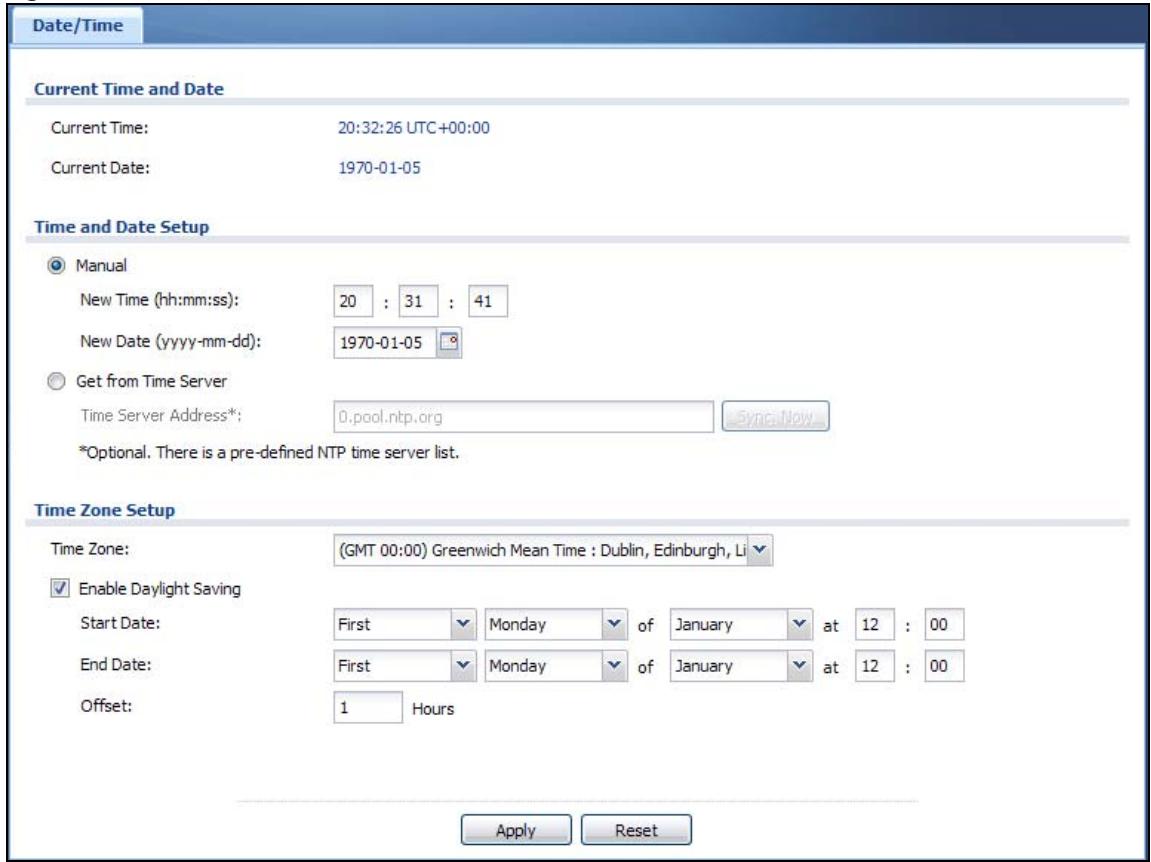
The following table describes the labels in this screen.
Table 65 Configuration > System > Date/Time
| LABEL | DESCRIPTION |
| Current Time and Date | |
| Current Time | This field displays the present time of your NWA/WAC. |
| Current Date | This field displays the present date of your NWA/WAC. |
| Time and Date Setup | |
| Manual | Select this radio button to enter the time and date manually. If you configure a new time and date, time zone and daylight saving at the same time, the time zone and daylight saving will affect the new time and date you entered. When you enter the time settings manually, the NWA/WAC uses the new setting once you clickApply. |
| New Time (hh:mm:ss) | This field displays the last updated time from the time server or the last time configured manually.When you setTime and Date Setupto Manual, enter the new time in this field and then clickApply. |
| New Date (yyyy-mm-dd) | This field displays the last updated date from the time server or the last date configured manually.When you setTime and Date Setupto Manual, enter the new date in this field and then clickApply. |
| Get from Time Server | Select this radio button to have the NWA/WAC get the time and date from the time server you specify below. The NWA/WAC requests time and date settings from the time server under the following circumstances.When the NWA/WAC starts up.When you clickApplyorSync.Nowin this screen.24-hour intervals after starting up. |
| Time Server Address | Enter the IP address or URL of your time server. Check with your ISP/network administrator if you are unsure of this information. |
| Sync. Now | Click this button to have the NWA/WAC get the time and date from a time server (see the Time Server Address field). This also saves your changes (except the daylight saving settings). |
| Time Zone Setup | |
| Time Zone | Choose the time zone of your location. This will set the time difference between your time zone and Greenwich Mean Time (GMT). |
| Enable Daylight Saving | Daylight saving is a period from late spring to fall when many countries set their clocks ahead of normal local time by one hour to give more daytime light in the evening.Select this option if you use Daylight Saving Time. |
| Start Date | Configure the day and time when Daylight Saving Time starts if you selectedEnable Daylight Saving.Theatfield uses the 24 hour format. Here are a couple of examples:Daylight Saving Time starts in most parts of the United States on the second Sunday of March. Each time zone in the United States starts using Daylight Saving Time at 2 A.M. local time. So in the United States you would selectSecond, Sunday, Marchand type 2 in theatfield.Daylight Saving Time starts in the European Union on the last Sunday of March. All of the time zones in the European Union start using Daylight Saving Time at the same moment (1 A.M. GMT or UTC). So in the European Union you would selectLast, Sunday, March. The time you type in theatfield depends on your time zone. In Germany for instance, you would type 2 because Germany's time zone is one hour ahead of GMT or UTC (GMT+1). |
| End Date | Configure the day and time when Daylight Saving Time ends if you selectedEnable Daylight Saving.Theatfield uses the 24 hour format. Here are a couple of examples:Daylight Saving Time ends in the United States on the first Sunday of November. Each time zone in the United States stops using Daylight Saving Time at 2 A.M. local time. So in the United States you would selectFirst, Sunday, Novemberand type 2 in theatfield.Daylight Saving Time ends in the European Union on the last Sunday of October. All of the time zones in the European Union stop using Daylight Saving Time at the same moment (1 A.M. GMT or UTC). So in the European Union you would selectLast, Sunday, October. The time you type in theatfield depends on your time zone. In Germany for instance, you would type 2 because Germany's time zone is one hour ahead of GMT or UTC (GMT+1). |
| Offset | Specify how much the clock changes when daylight saving begins and ends.Enter a number from 1 to 5.5 (by 0.5 increments).For example, if you set this field to 3.5, a log occurred at 6 P.M. in local official time will appear as if it had occurred at 10:30 P.M. |
| Apply | ClickApplyto save your changes back to the NWA/WAC. |
| Reset | ClickResetto return the screen to its last-saved settings. |
12.3.1 Pre-defined NTP Time Servers List
When you turn on the NWA/WAC for the first time, the date and time start at 2003-01-01 00:00:00. The NWA/WAC then attempts to synchronize with one of the following pre-defined list of Network Time Protocol (NTP) time servers.
The NWA/WAC continues to use the following pre-defined list of NTP time servers if you do not specify a time server or it cannot synchronize with the time server you specified.
Table 66 Default Time Servers
| 0.pool.ntp.org |
| 1.pool.ntp.org |
| 2.pool.ntp.org |
When the NWA/WAC uses the pre-defined list of NTP time servers, it randomly selects one server and tries to synchronize with it. If the synchronization fails, then the NWA/WAC goes through the rest of the list in order from the first one tried until either it is successful or all the pre-defined NTP time servers have been tried.
12.3.2 Time Server Synchronization
Click the Sync. Now button to get the time and date from the time server you specified in the Time Server Address field.
When the Loading message appears, you may have to wait up to one minute.
Figure 76 Loading
The Current Time and Current Date fields will display the appropriate settings if the synchronization is successful.
If the synchronization was not successful, a log displays in the View Log screen. Try re-configuring the Date/Time screen.
To manually set the NWA/WAC date and time:
1 Click System > Date/Time.
2 Select Manual under Time and Date Setup.
3 Enter the NWA/WAC's time in the New Time field.
4 Enter the NWA/WAC's date in the New Date field.
5 Under Time Zone Setup, select your Time Zone from the list.
6 As an option you can select the Enable Daylight Saving check box to adjust the NWA/WAC clock for daylight savings.
7 Click Apply.
To get the NWA/WAC date and time from a time server:
1 Click System > Date/Time.
2 Select Get from Time Server under Time and Date Setup.
3 Under Time Zone Setup, select your Time Zone from the list.
4 Under Time and Date Setup, enter a Time Server Address.
5 Click Apply.
12.4 WWW Overview
The following figure shows secure and insecure management of the NWA/WAC coming in from the WAN. HTTPS and SSH access are secure. HTTP, Telnet, and FTP management access are not secure.
Figure 77 Secure and Insecure Service Access From the WAN
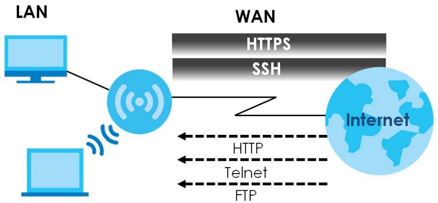
flowchart
graph TD
    A["LAN"] --> B["Wi"]
    B --> C["WAN"]
    C --> D["Internet"]
    D --> E["HTTPS"]
    D --> F["SSH"]
    D --> G["HTTP"]
    D --> H["Telnet"]
    D --> I["FTP"]
12.4.1 Service Access Limitations
A service cannot be used to access the NWA/WAC when you have disabled that service in the corresponding screen.
12.4.2 System Timeout
There is a lease timeout for administrators. The NWA/WAC automatically logs you out if the management session remains idle for longer than this timeout period. The management session does not time out when a statistics screen is polling.
Each user is also forced to log in the NWA/WAC for authentication again when the reauthentication time expires.
You can change the timeout settings in the User screens.
12.4.3 HTTPS
You can set the NWA/WAC to use HTTP or HTTPS (HTTPS adds security) for Web Configurator sessions.
HTTPS (HyperText Transfer Protocol over Secure Socket Layer, or HTTP over SSL) is a web protocol that encrypts and decrypts web pages. Secure Socket Layer (SSL) is an application-level protocol that enables secure transactions of data by ensuring confidentiality (an unauthorized party cannot read the transferred data), authentication (one party can identify the other party) and data integrity (you know if data has been changed).
It relies upon certificates, public keys, and private keys (see Chapter 11 on page 114 for more information).
HTTPS on the NWA/WAC is used so that you can securely access the NWA/WAC using the Web Configurator. The SSL protocol specifies that the HTTPS server (the NWA/WAC) must always authenticate itself to the HTTPS client (the computer which requests the HTTPS connection with the NWA/WAC), whereas the HTTPS client only should authenticate itself when the HTTPS server requires it to do so (select Authenticate Client Certificates in the WWW screen). Authenticate Client Certificates is optional and if selected means the HTTPS client must send the NWA/WAC a certificate. You must apply for a certificate for the browser from a CA that is a trusted CA on the NWA/WAC.
Please refer to the following figure.
1 HTTPS connection requests from an SSL-aware web browser go to port 443 (by default) on the NWA/WAC's web server.
2 HTTP connection requests from a web browser go to port 80 (by default) on the NWA/WAC's web server.
Figure 78 HTTP/HTTPS Implementation
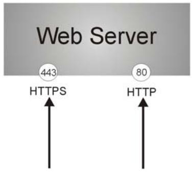
Note: If you disable HTTP in the WWW screen, then the NWA/WAC blocks all HTTP connection attempts.
12.4.4 Configuring WWW Service Control
Click Configuration > System > WWW to open the WWW screen. Use this screen to specify HTTP or HTTPS settings.
Figure 79 Configuration > System > WWW > Service Control
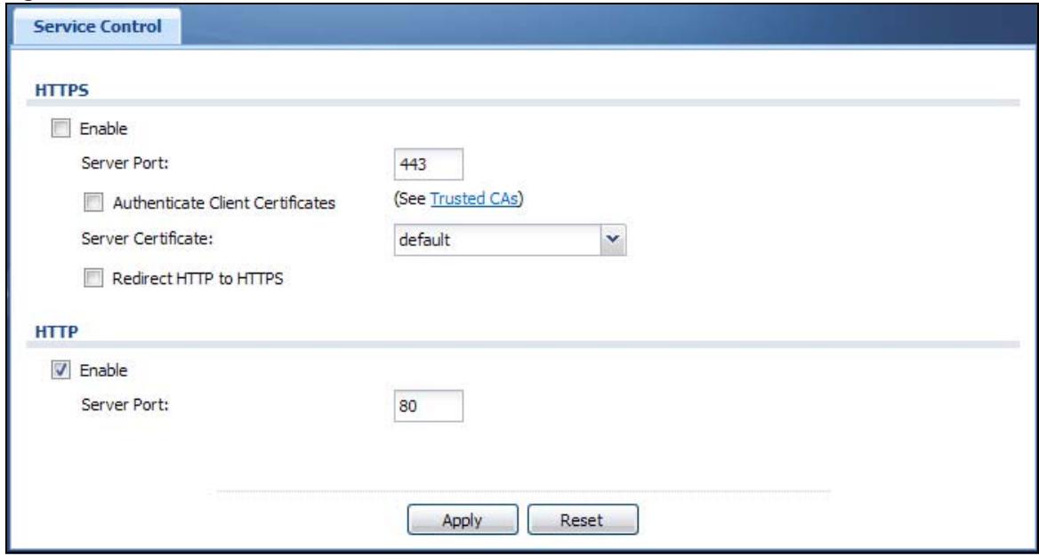
The following table describes the labels in this screen.
Table 67 Configuration > System > WWW > Service Control
| LABEL | DESCRIPTION |
| HTTPS | |
| Enable | Select the check box to allow or disallow the computer with the IP address that matches the IP address(es) in the Service Control table to access the NWA/WAC Web Configurator using secure HTTPS connections. |
| Server Port | The HTTPS server listens on port 443 by default. If you change the HTTPS server port to a different number on the NWA/WAC, for example 8443, then you must notify people who need to access the NWA/WAC Web Configurator to use “https://NWA/WAC IP Address:8443” as the URL. |
| Authenticate Client Certificates | Select Authenticate Client Certificates (optional) to require the SSL client to authenticate itself to the NWA/WAC by sending the NWA/WAC a certificate. To do that the SSL client must have a CA-signed certificate from a CA that has been imported as a trusted CA on the NWA/WAC. |
| Server Certificate | Select a certificate the HTTPS server (the NWA/WAC) uses to authenticate itself to the HTTPS client. You must have certificates already configured in the My Certificates screen. |
| Redirect HTTP to HTTPS | To allow only secure Web Configurator access, select this to redirect all HTTP connection requests to the HTTPS server. |
| HTTP | |
| Enable | Select the check box to allow or disallow the computer with the IP address that matches the IP address(es) in the Service Control table to access the NWA/WAC Web Configurator using HTTP connections. |
| Server Port | You may change the server port number for a service if needed, however you must use the same port number in order to use that service to access the NWA/WAC. |
| Apply | Click Apply to save your changes back to the NWA/WAC. |
| Reset | Click Reset to return the screen to its last-saved settings. |
12.4.5 HTTPS Example
If you haven't changed the default HTTPS port on the NWA/WAC, then in your browser enter "https://NWA/WAC IP Address/" as the web site address where "NWA/WAC IP Address" is the IP address or domain name of the NWA/WAC you wish to access.
12.4.5.1 Internet Explorer Warning Messages
When you attempt to access the NWA/WAC HTTPS server, you will see the error message shown in the following screen.
Figure 80 Security Alert Dialog Box (Internet Explorer)
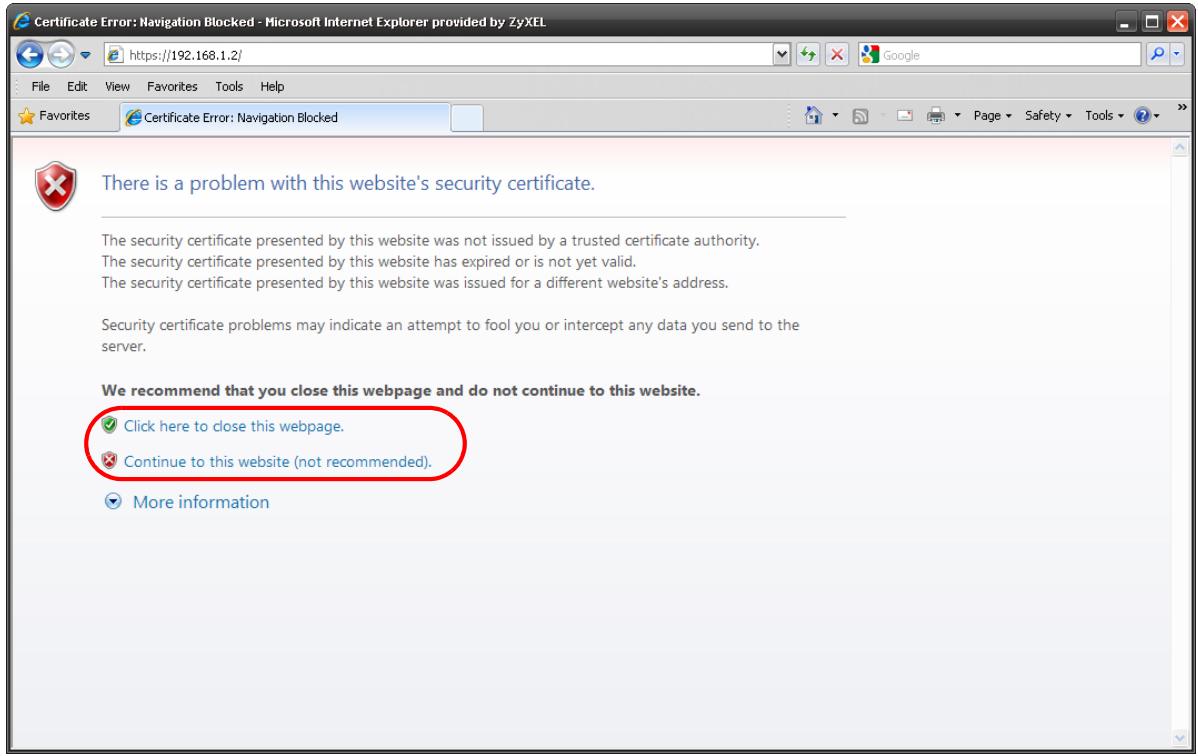
Select Continue to this website. to proceed to the Web Configurator login screen. Otherwise, select Click here to close this webpage. to block the access.
12.4.5.2 Mozilla Firefox Warning Messages
When you attempt to access the NWA/WAC HTTPS server, a The Connection is Untrusted screen appears as shown in the following screen. Click Technical Details if you want to verify more information about the certificate from the NWA/WAC.
Select I Understand the Risks and then click Add Exception to add the NWA/WAC to the security exception list. Click Confirm Security Exception.
Figure 81 Security Certificate 1 (Firefox)
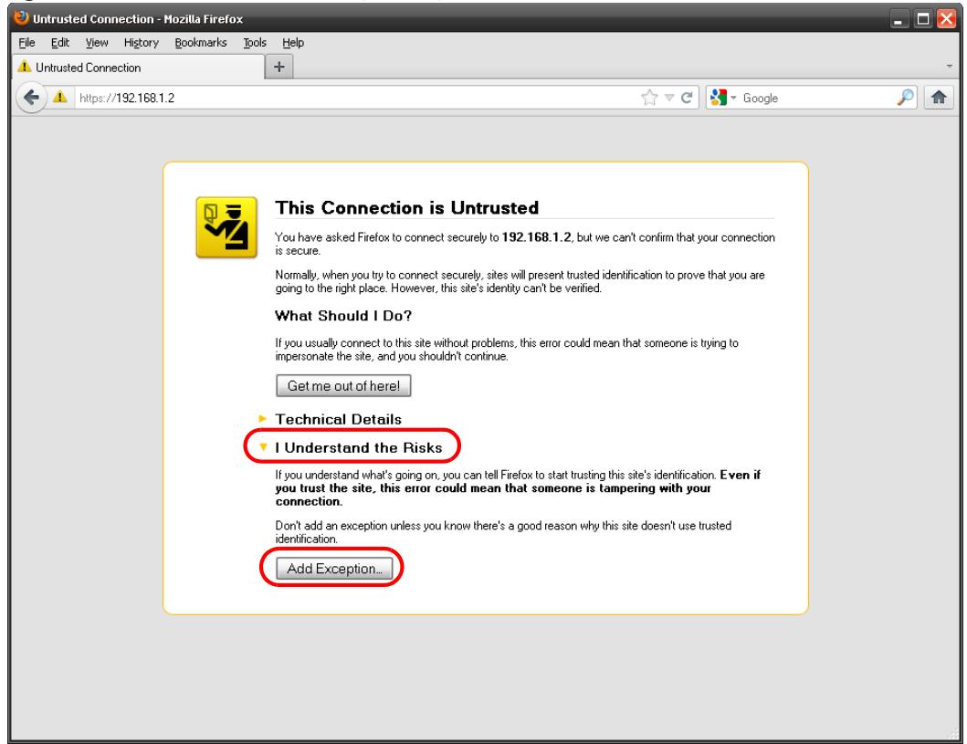
Figure 82 Security Certificate 2 (Firefox)
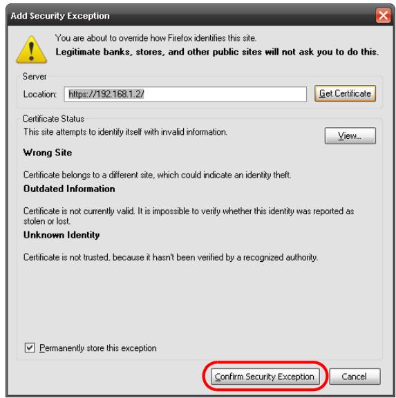
12.4.5.3 Avoiding Browser Warning Messages
Here are the main reasons your browser displays warnings about the NWA/WAC's HTTPS server certificate and what you can do to avoid seeing the warnings:
- The issuing certificate authority of the NWA/WAC's HTTPS server certificate is not one of the browser's trusted certificate authorities. The issuing certificate authority of the NWA/WAC's factory default certificate is the NWA/WAC itself since the certificate is a self-signed certificate.
- For the browser to trust a self-signed certificate, import the self-signed certificate into your operating system as a trusted certificate.
- To have the browser trust the certificates issued by a certificate authority, import the certificate authority's certificate into your operating system as a trusted certificate. Refer to Appendix A on page 199 for details.
12.4.5.4 Enrolling and Importing SSL Client Certificates
The SSL client needs a certificate if Authenticate Client Certificates is selected on the NWA/WAC.
You must have imported at least one trusted CA to the NWA/WAC in order for the Authenticate Client Certificates to be active (see the Certificates chapter for details).
Apply for a certificate from a Certification Authority (CA) that is trusted by the NWA/WAC (see the NWA/WAC's Trusted Certificates Web Configurator screen).
Figure 83 Trusted Certificates
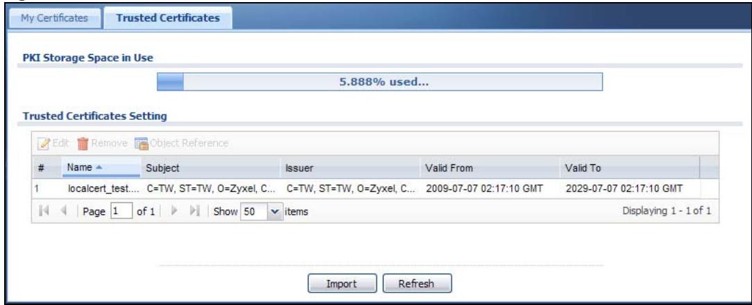
The CA sends you a package containing the CA's trusted certificate(s), your personal certificate(s) and a password to install the personal certificate(s).
12.4.5.5 Installing the CA's Certificate
1 Double click the CA's trusted certificate to produce a screen similar to the one shown next.
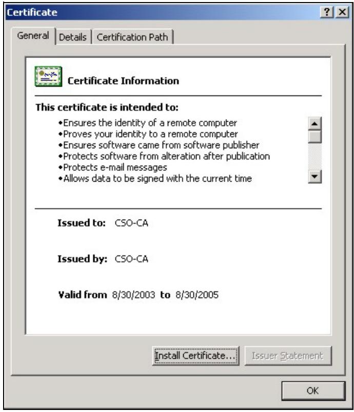
2 Click Install Certificate and follow the wizard as shown.
12.4.5.6 Installing a Personal Certificate
You need a password in advance. The CA may issue the password or you may have to specify it during the enrollment. Double-click the personal certificate given to you by the CA to produce a screen similar to the one shown next.
1 Click Next to begin the wizard.
2 The file name and path of the certificate you double-clicked should automatically appear in the File name text box. Click Browse if you wish to import a different certificate.
3 Enter the password given to you by the CA.
4 Have the wizard determine where the certificate should be saved on your computer or select Place all certificates in the following store and choose a different location.
5 Click Finish to complete the wizard and begin the import process.
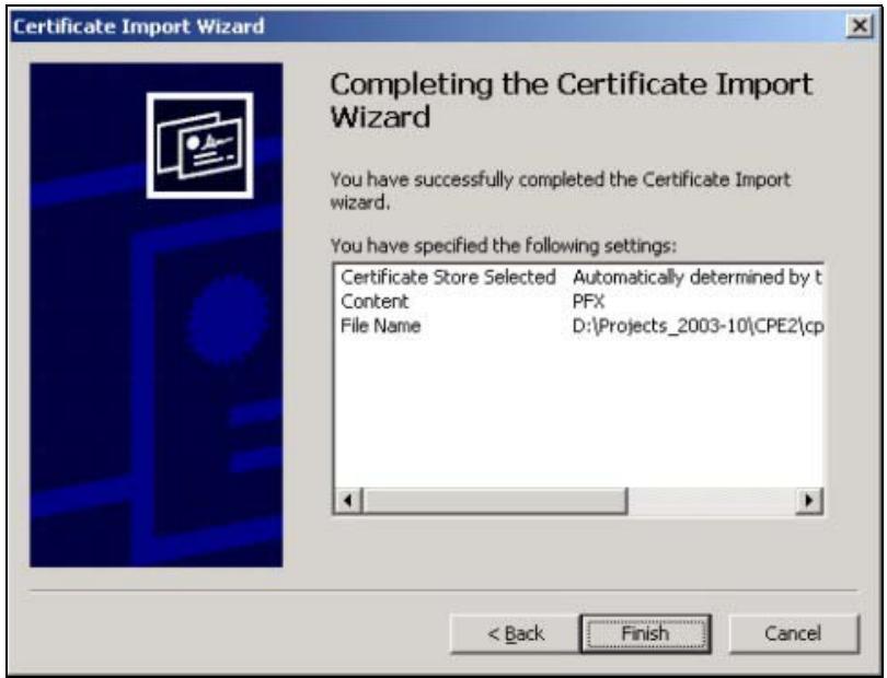
6 You should see the following screen when the certificate is correctly installed on your computer.
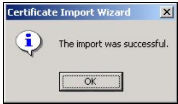
12.4.5.7 Using a Certificate When Accessing the NWA/WAC
To access the NWA/WAC via HTTPS:
1 Enter 'https://NWA/WAC IP Address/' in your browser's web address field.
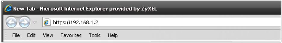
2 When Authenticate Client Certificates is selected on the NWA/WAC, the following screen asks you to select a personal certificate to send to the NWA/WAC. This screen displays even if you only have a single certificate as in the example.
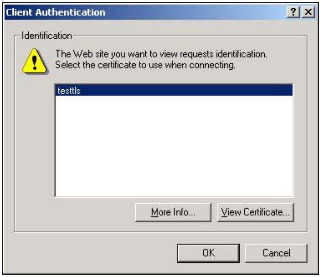
3 You next see the Web Configurator login screen.
12.5 SSH
You can use SSH (Secure SHell) to securely access the NWA/WAC's command line interface.
SSH is a secure communication protocol that combines authentication and data encryption to provide secure encrypted communication between two hosts over an unsecured network. In the following figure, computer B on the Internet uses SSH to securely connect to the NWA/WAC (A) for a management session.
Figure 84 SSH Communication Over the WAN Example
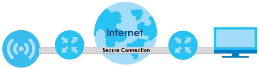
flowchart
graph LR
    A["Internet"] --> B["Secure Connection"]
    B --> C["Computer"]
12.5.1 How SSH Works
The following figure is an example of how a secure connection is established between two remote hosts using SSH v1.
Figure 85 How SSH v1 Works Example
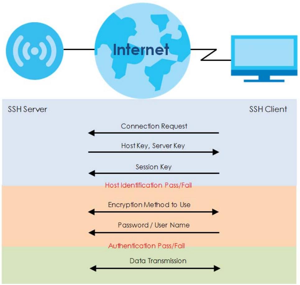
flowchart
graph TD
    A["Internet"] -->|Z| B["SSH Client"]
    C["SSH Server"] -->|Connection Request| A
    C -->|Host Key, Server Key| A
    C -->|Session Key| A
    C -->|Host Identification Pass/Fail| B
    C -->|Encryption Method to Use| B
    C -->|Password / User Name| B
    C -->|Authentication Pass/Fail| B
    C -->|Data Transmission| B
1 Host Identification
The SSH client sends a connection request to the SSH server. The server identifies itself with a host key. The client encrypts a randomly generated session key with the host key and server key and sends the result back to the server.
The client automatically saves any new server public keys. In subsequent connections, the server public key is checked against the saved version on the client computer.
2 Encryption Method
Once the identification is verified, both the client and server must agree on the type of encryption method to use.
3 Authentication and Data Transmission
After the identification is verified and data encryption activated, a secure tunnel is established between the client and the server. The client then sends its authentication information (user name and password) to the server to log in to the server.
12.5.2 SSH Implementation on the NWA/WAC
Your NWA/WAC supports SSH versions 1 and 2 using RSA authentication and four encryption methods (AES, 3DES, Archfour, and Blowfish). The SSH server is implemented on the NWA/WAC for management using port 22 (by default).
12.5.3 Requirements for Using SSH
You must install an SSH client program on a client computer (Windows or Linux operating system) that is used to connect to the NWA/WAC over SSH.
12.5.4 Configuring SSH
Click Configuration > System > SSH to open the following screen. Use this screen to configure your NWA/WAC's Secure Shell settings.
Note: It is recommended that you disable Telnet and FTP when you configure SSH for secure connections.
Figure 86 Configuration > System > SSH
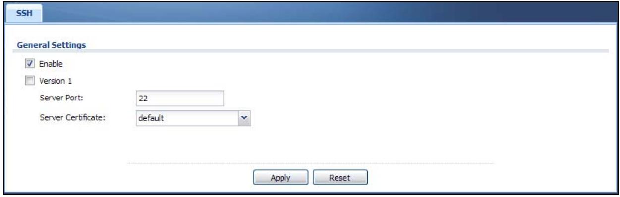
The following table describes the labels in this screen.
Table 68 Configuration > System > SSH
| LABEL | DESCRIPTION |
| Enable | Select the check box to allow or disallow the computer with the IP address that matches the IP address(es) in the Service Control table to access the NWA/WAC CLI using this service. |
| Version 1 | Select the check box to have the NWA/WAC use both SSH version 1 and version 2 protocols. If you clear the check box, the NWA/WAC uses only SSH version 2 protocol. |
| Server Port | You may change the server port number for a service if needed, however you must use the same port number in order to use that service for remote management. |
| Server Certificate | Select the certificate whose corresponding private key is to be used to identify the NWA/WAC for SSH connections. You must have certificates already configured in the My Certificates screen. |
| Apply | Click Apply to save your changes back to the NWA/WAC. |
| Reset | Click Reset to return the screen to its last-saved settings. |
12.5.5 Examples of Secure Telnet Using SSH
This section shows two examples using a command interface and a graphical interface SSH client program to remotely access the NWA/WAC. The configuration and connection steps are similar for most SSH client programs. Refer to your SSH client program user's guide.
12.5.5.1 Example 1: Microsoft Windows
This section describes how to access the NWA/WAC using the Secure Shell Client program.
1 Launch the SSH client and specify the connection information (IP address, port number) for the NWA/WAC.
2 Configure the SSH client to accept connection using SSH version 1.
3 A window displays prompting you to store the host key in you computer. Click Yes to continue.
Figure 87 SSH Example 1: Store Host Key
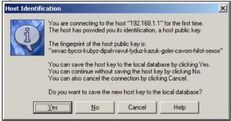
Enter the password to log in to the NWA/WAC. The CLI screen displays next.
12.5.5.2 Example 2: Linux
This section describes how to access the NWA/WAC using the OpenSSH client program that comes with most Linux distributions.
1 Test whether the SSH service is available on the NWA/WAC.
Enter "telnet 192.168.1.2 22" at a terminal prompt and press [ENTER]. The computer attempts to connect to port 22 on the NWA/WAC (using the default IP address of 192.168.1.2).
A message displays indicating the SSH protocol version supported by the NWA/WAC.
Figure 88 SSH Example 2: Test
$ telnet 192.168.1.2 22
Trying 192.168.1.2...
Connected to 192.168.1.2.
Escape character is '^]'.
SSH-1.5-1.0.0
2 Enter "ssh -1 192.168.1.2". This command forces your computer to connect to the NWA/WAC using SSH version 1. If this is the first time you are connecting to the NWA/WAC using SSH, a message displays prompting you to save the host information of the NWA/WAC. Type "yes" and press [ENTER].
Then enter the password to log in to the NWA/WAC.
Figure 89 SSH Example 2: Log in
$ ssh -1 192.168.1.2
The authenticity of host '192.168.1.2 (192.168.1.2)' can't be established.
RSA1 key fingerprint is 21:6c:07:25:7e:f4:75:80:ec:af:bd:d4:3d:80:53:d1.
Are you sure you want to continue connecting (yes/no)? yes
Warning: Permanently added '192.168.1.2' (RSA1) to the list of known hosts.
Administrator@192.168.1.2's password:
3 The CLI screen displays next.
12.6 Telnet
You can use Telnet to access the NWA/WAC's command line interface. Click Configuration > System > TELNET to configure your NWA/WAC for remote Telnet access. Use this screen to enable or disable Telnet and set the server port number.
Figure 90 Configuration > System > TELNET
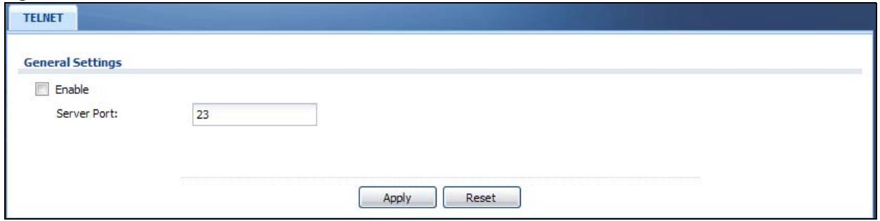
The following table describes the labels in this screen.
Table 69 Configuration > System > TELNET
| LABEL | DESCRIPTION |
| Enable | Select the check box to allow or disallow the computer with the IP address that matches the IP address(es) in the Service Control table to access the NWA/WAC CLI using this service. |
| Server Port | You may change the server port number for a service if needed, however you must use the same port number in order to use that service for remote management. |
| Apply | Click Apply to save your changes back to the NWA/WAC. |
| Reset | Click Reset to return the screen to its last-saved settings. |
12.7 FTP
You can upload and download the NWA/WAC's firmware and configuration files using FTP. To use this feature, your computer must have an FTP client. See Chapter 14 on page 169 for more information about firmware and configuration files.
To change your NWA/WAC's FTP settings, click Configuration > System > FTP tab. The screen appears as shown. Use this screen to specify FTP settings.
Figure 91 Configuration > System > FTP
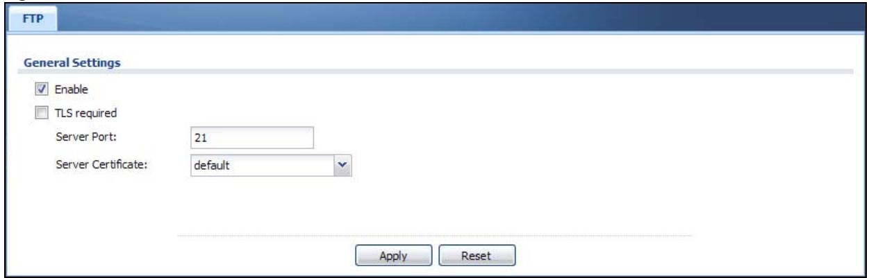
The following table describes the labels in this screen.
Table 70 Configuration > System > FTP
| LABEL | DESCRIPTION |
| Enable | Select the check box to allow or disallow the computer with the IP address that matches the IP address(es) in theService Controltable to access the NWA/WAC using this service. |
| TLS required | Select the check box to use FTP over TLS (Transport Layer Security) to encrypt communication.This implements TLS as a security mechanism to secure FTP clients and/or servers. |
| Server Port | You may change the server port number for a service if needed, however you must use the same port number in order to use that service for remote management. |
| Server Certificate | Select the certificate whose corresponding private key is to be used to identify the NWA/WAC for FTP connections. You must have certificates already configured in theMy Certificates screen. |
| Apply | ClickApplyto save your changes back to the NWA/WAC. |
| Reset | ClickResetto return the screen to its last-saved settings. |
12.8 SNMP
Simple Network Management Protocol is a protocol used for exchanging management information between network devices. Your NWA/WAC supports SNMP agent functionality, which allows a manager station to manage and monitor the NWA/WAC through the network. The NWA/WAC supports SNMP version one (SNMPv1), version two (SNMPv2c), and version three (SNMPv3). The next figure illustrates an SNMP management operation.
Figure 92 SNMP Management Model
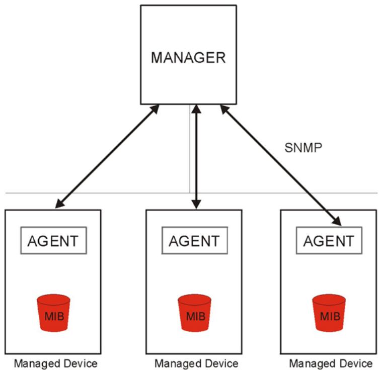
flowchart
graph TD
    A["MANAGER"] --> B["AGENT"]
    A --> C["AGENT"]
    A --> D["AGENT"]
    B --> E["Managed Device"]
    C --> F["Managed Device"]
    D --> G["Managed Device"]
    style A fill:#f9f,stroke:#333
    style B fill:#ccf,stroke:#333
    style C fill:#ccf,stroke:#333
    style D fill:#ccf,stroke:#333
    linkStyle 0 stroke:#000,stroke-width:2px
    linkStyle 1 stroke:#000,stroke-width:2px
    linkStyle 2 stroke:#000,stroke-width:2px
    linkStyle 3 stroke:#000,stroke-width:2px
    linkStyle 4 stroke:#000,stroke-width:2px
    linkStyle 5 stroke:#000,stroke-width:2px
    linkStyle 6 stroke:#000,stroke-width:2px
    linkStyle 7 stroke:#000,stroke-width:2px
    linkStyle 8 stroke:#000,stroke-width:2px
    linkStyle 9 stroke:#000,stroke-width:2px
    linkStyle 10 stroke:#000,stroke-width:2px
    linkStyle 11 stroke:#000,stroke-width:2px
    linkStyle 12 stroke:#000,stroke-width:2px
    linkStyle 13 stroke:#000,stroke-width:2px
    linkStyle 14 stroke:#000,stroke-width:2px
    linkStyle 15 stroke:#000,stroke-width:2px
    linkStyle 16 stroke:#000,stroke-width:2px
    linkStyle 17 stroke:#000,stroke-width:2px
    linkStyle 18 stroke:#000,stroke-width:2px
    linkStyle 19 stroke:#000,stroke-width:2px
    linkStyle 20 stroke:#000,stroke-width:2px
    linkStyle 21 stroke:#000,stroke-width:2px
    linkStyle 22 stroke:#000,stroke-width:2px
    linkStyle 23 stroke:#000,stroke-width:2px
    linkStyle 24 stroke:#000,stroke-width:2px
    linkStyle 25 stroke:#000,stroke-width:2px
    linkStyle 26 stroke:#000,stroke-width:2px
    linkStyle 27 stroke:#000,stroke-width:2px
    linkStyle 28 stroke:#000,stroke-width:2px
    linkStyle 29 stroke:#000,stroke-width:2px
    linkStyle 30 stroke:#000,stroke-width:2px
    linkStyle 31 stroke:#000,stroke-width:2px
    linkStyle 32 stroke:#000,stroke-width:2px
    linkStyle 33 stroke:#000,stroke-width:2px
    linkStyle 34 stroke:#000,stroke-width:2px
    linkStyle 35 stroke:#000,stroke-width:2px
    linkStyle 36 stroke:#000,stroke-width:2px
    linkStyle 37 stroke:#000,stroke-width:2px
    linkStyle 38 stroke:#000,stroke-width:2px
    linkStyle 39 stroke:#000,stroke-width:2px
    linkStyle 40 stroke:#000,stroke-width:2px
    linkStyle 41 stroke:#000,stroke-width:2px
    linkStyle 42 stroke:#000,stroke-width:2px
    linkStyle 43 stroke:#000,stroke-width:2px
    linkStyle 44 stroke:#000,stroke-width:2px
    linkStyle 45 stroke:#000,stroke-width:2px
    linkStyle 46 stroke:#000,stroke-width:2px
    linkStyle 47 stroke:#000,stroke-width:2px
    linkStyle 48 stroke:#000,stroke-width:2px
    linkStyle 49 stroke:#000,stroke-width:2px
    linkStyle 50 stroke:#000,stroke-width:2px
An SNMP managed network consists of two main types of component: agents and a manager.
An agent is a management software module that resides in a managed device (the NWA/WAC). An agent translates the local management information from the managed device into a form compatible with SNMP. The manager is the console through which network administrators perform network management functions. It executes applications that control and monitor managed devices.
The managed devices contain object variables/managed objects that define each piece of information to be collected about a device. Examples of variables include such as number of packets received, node port status etc. A Management Information Base (MIB) is a collection of managed objects. SNMP allows a manager and agents to communicate for the purpose of accessing these objects.
SNMP itself is a simple request/response protocol based on the manager/agent model. The manager issues a request and the agent returns responses using the following protocol operations:
- Get - Allows the manager to retrieve an object variable from the agent.
- GetNext - Allows the manager to retrieve the next object variable from a table or list within an agent. In SNMPv1, when a manager wants to retrieve all elements of a table from an agent, it initiates a Get operation, followed by a series of GetNext operations.
- Set - Allows the manager to set values for object variables within an agent.
- Trap - Used by the agent to inform the manager of some events.
12.8.1 Supported MIBs
The NWA/WAC supports MIB II that is defined in RFC-1213 and RFC-1215. The NWA/WAC also supports private MIBs (ZYXEL-ES-CAPWAP.MIB, ZYXEL-ES-COMMON.MIB, ZYXEL-ES-ZyXELAPMgmt.MIB, ZYXEL-ES-PROWLAN.MIB, ZYXEL-ES-RFMGMT.MIB, ZYXEL-ES-SMI.MIB, and ZYXEL-ES-WIRELESS.MIB) to collect information about CPU and memory usage and VPN total throughput. The focus of the MIBs is to let
administrators collect statistical data and monitor status and performance. You can download the NWA/WAC's MIBs from www.zyxel.com.
12.8.2 SNMP Traps
The NWA/WAC will send traps to the SNMP manager when any one of the following events occurs.
Table 71 SNMP Traps
| OBJECT LABEL | OBJECT ID | DESCRIPTION |
| linkDown | 1.3.6.1.6.3.1.1.5.3 | This trap is sent when the Ethernet link is down. |
| linkUp | 1.3.6.1.6.3.1.1.5.4 | This trap is sent when the Ethernet link is up. |
| authenticationFailure | 1.3.6.1.6.3.1.1.5.5 | This trap is sent when an SNMP request comes from non-authenticated hosts. |
12.8.3 Configuring SNMP
To change your NWA/WAC's SNMP settings, click Configuration > System > SNMP tab. The screen appears as shown. Use this screen to configure your SNMP settings. You can also configure user profiles that define allowed SNMPv3 access.
Figure 93 Configuration > System > SNMP
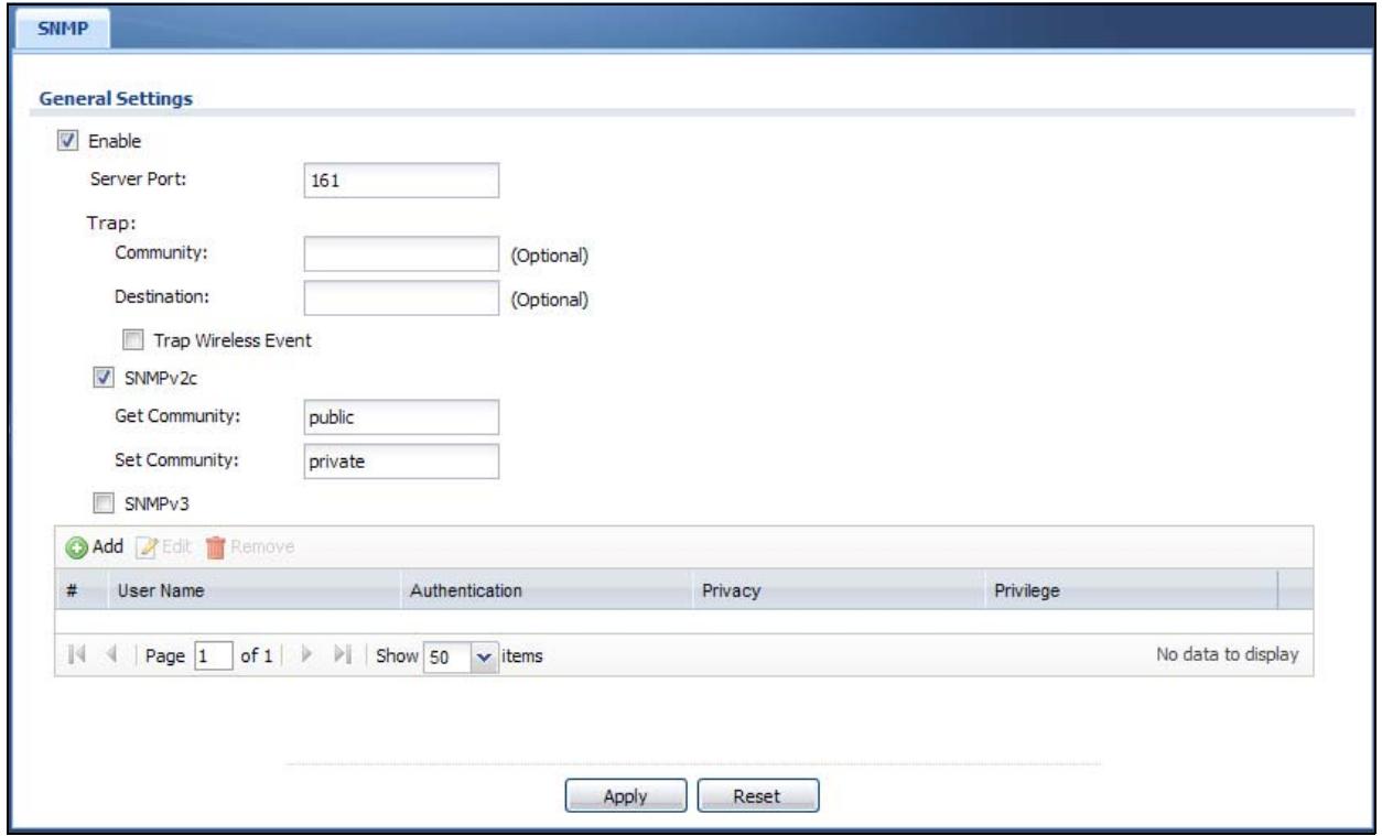
The following table describes the labels in this screen.
Table 72 Configuration > System > SNMP
| LABEL | DESCRIPTION |
| Enable | Select the check box to allow or disallow users to access the NWA/WAC using SNMP. |
| Server Port | You may change the server port number for a service if needed, however you must use the same port number in order to use that service for remote management. |
| Trap | |
| Community | Type the trap community, which is the password sent with each trap to the SNMP manager. The default is public and allows all requests. |
| Destination | Type the IP address of the station to send your SNMP traps to. |
| Trap Wireless Event | Select this to have the NWA/WAC send a trap to the SNMP manager when a wireless client is connected to or disconnected from the NWA/WAC. |
| SNMPv2c | Select this to allow SNMP managers using SNMPv2c to access the NWA/WAC. |
| Get Community | Enter the Get Community, which is the password for the incoming Get and GetNext requests from the management station. The default is public and allows all requests. |
| Set Community | Enter the Set community, which is the password for incoming Set requests from the management station. The default is private and allows all requests. |
| SNMPv3 | Select this to allow SNMP managers using SNMPv3 to access the NWA/WAC. |
| Add | Click this to create a new entry. Select an entry and click Add to create a new entry after the selected entry. |
| Edit | Double-click an entry or select it and click Edit to be able to modify the entry's settings. |
| Remove | To remove an entry, select it and click Remove. The NWA/WAC confirms you want to remove it before doing so. Note that subsequent entries move up by one when you take this action. |
| # | This the index number of an SNMPv3 user profile. |
| User Name | This is the name of the user for which this SNMPv3 user profile is configured. |
| Authentication | This field displays the type of authentication the SNMPv3 user must use to connect to the NWA/WAC using this SNMPv3 user profile. |
| Privacy | This field displays the type of encryption the SNMPv3 user must use to connect to the NWA/WAC using this SNMPv3 user profile. |
| Privilege | This field displays whether the SNMPv3 user can have read-only or read and write access to the NWA/WAC using this SNMPv3 user profile. |
| Apply | Click Apply to save your changes back to the NWA/WAC. |
| Reset | Click Reset to return the screen to its last-saved settings. |
12.8.4 Adding or Editing an SNMPv3 User Profile
This screen allows you to add or edit an SNMPv3 user profile. To access this screen, click the Configuration > System > SNMP screen's Add button or select a SNMPv3 user profile from the list and click the Edit button.
Figure 94 Configuration > System > SNMP > Add
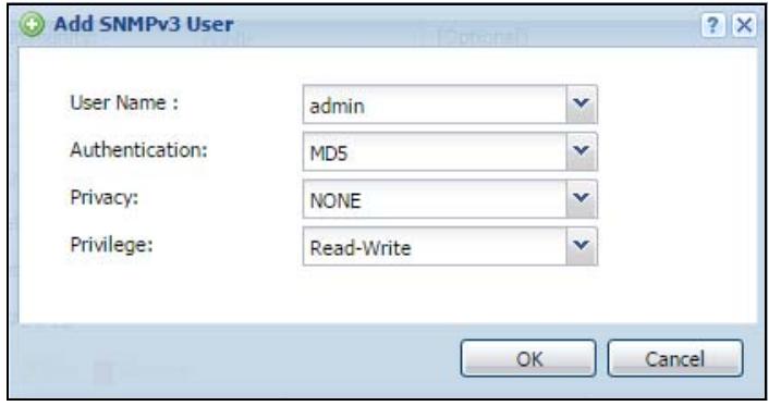
The following table describes the labels in this screen.
Table 73 Configuration > System > SNMP
| LABEL | DESCRIPTION |
| User Name | Select the user name of the user account for which this SNMPv3 user profile is configured. |
| Authentication | Select the type of authentication the SNMPv3 user must use to connect to the NWA/WAC using this SNMPv3 user profile.Select MD5 to require the SNMPv3 user's password be encrypted by MD5 for authentication.Select SHA to require the SNMPv3 user's password be encrypted by SHA for authentication. |
| Privacy | Select the type of encryption the SNMPv3 user must use to connect to the NWA/WAC using this SNMPv3 user profile.Select NONE to not encrypt the SNMPv3 communications.Select DES to use DES to encrypt the SNMPv3 communications.Select AES to use AES to encrypt the SNMPv3 communications. |
| Privilege | Select whether the SNMPv3 user can have read-only or read and write access to the NWA/WAC using this SNMPv3 user profile. |
| OK | Click OK to save your changes back to the NWA/WAC. |
| Cancel | Click Cancel to exit this screen without saving your changes. |
CHAPTER 13
Log and Report
13.1 Overview
Use the system screens to configure daily reporting and log settings.
13.1.1 What You Can Do In this Chapter
- The Email Daily Report screen (Section 13.2 on page 156) configures how and where to send daily reports and what reports to send.
- The Log Setting screens (Section 13.3 on page 158) specify which logs are e-mailed, where they are e-mailed, and how often they are e-mailed.
13.2 Email Daily Report
Use this screen to start or stop data collection and view various statistics about traffic passing through your NWA/WAC.
Note: Data collection may decrease the NWA/WAC's traffic throughput rate.
Click Configuration > Log & Report > Email Daily Report to display the following screen. Configure this screen to have the NWA/WAC e-mail you system statistics every day.
Figure 95 Configuration > Log & Report > Email Daily Report
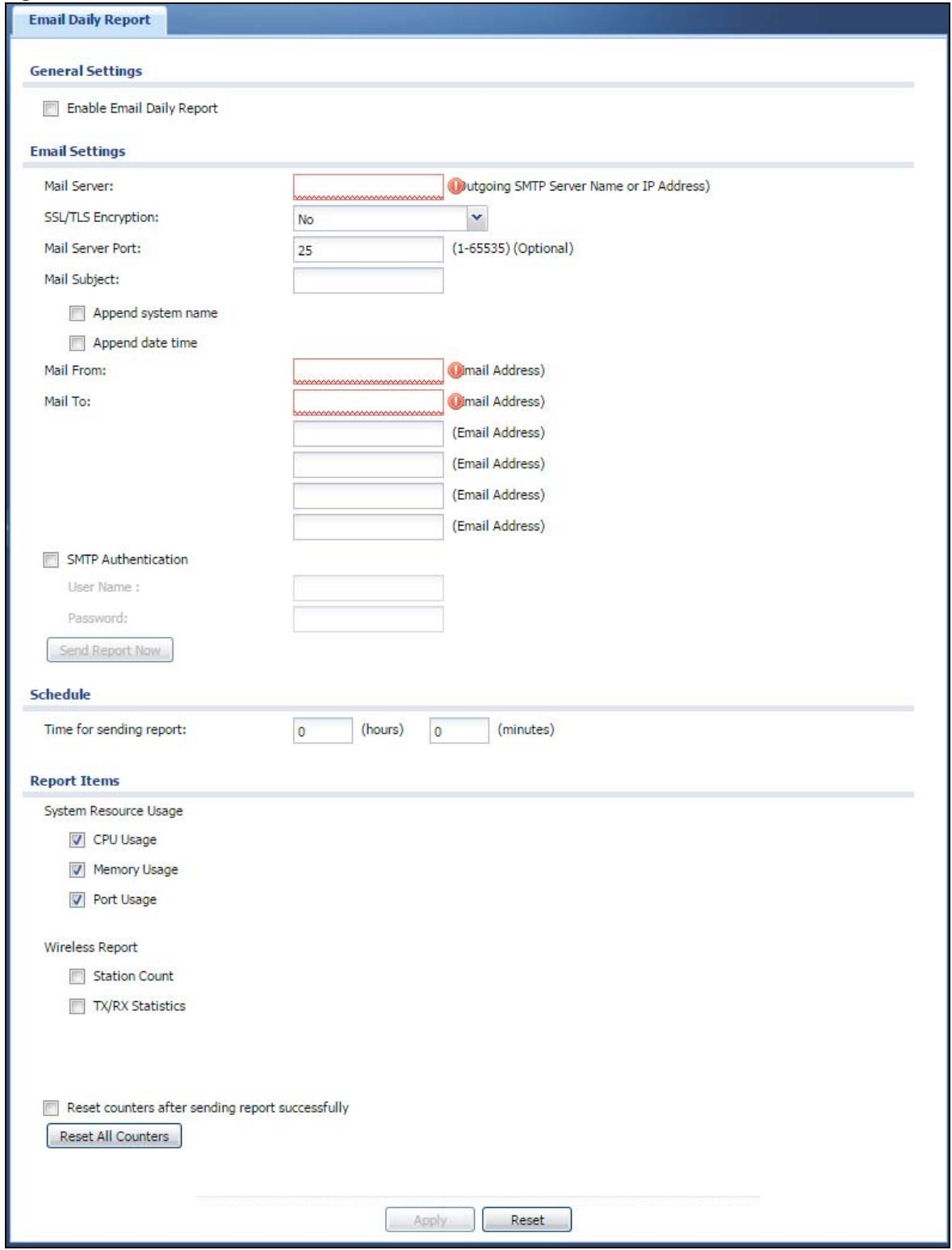
The following table describes the labels in this screen.
Table 74 Configuration > Log & Report > Email Daily Report
| LABEL | DESCRIPTION |
| Enable Email Daily Report | Select this to send reports by e-mail every day. |
| Mail Server | Type the name or IP address of the outgoing SMTP server. |
| SSL/TLS Encryption | Select SSL/TLS to use Secure Sockets Layer (SSL) or Transport Layer Security (TLS) if you want encrypted communications between the mail server and the NWA/WAC.Select STARTTLS to upgrade a plain text connection to a secure connection using SSL/TLS.Select No to not encrypt the communications. |
| Mail Server Port | Enter the same port number here as is on the mail server for mail traffic. |
| Mail Subject | Type the subject line for the outgoing e-mail. Select Append system name to add the NWA/WAC's system name to the subject. Select Append date time to add the NWA/WAC's system date and time to the subject. |
| Mail From | Type the e-mail address from which the outgoing e-mail is delivered. This address is used in replies. |
| Mail To | Type the e-mail address (or addresses) to which the outgoing e-mail is delivered. |
| SMTP Authentication | Select this check box if it is necessary to provide a user name and password to the SMTP server. |
| User Name | This box is effective when you select the SMTP Authentication check box. Type the user name to provide to the SMTP server when the log is e-mailed. |
| Password | This box is effective when you select the SMTP Authentication check box. Type the password to provide to the SMTP server when the log is e-mailed. |
| Send Report Now | Click this button to have the NWA/WAC send the daily e-mail report immediately. |
| Time for sending report | Select the time of day (hours and minutes) when the log is e-mailed. Use 24-hour notation. |
| Report Items | Select the information to include in the report. Select Reset counters after sending report successfully if you only want to see statistics for a 24 hour period. |
| Reset All Counters | Click this to discard all report data and start all of the counters over at zero. |
| Apply | Click Apply to save your changes back to the NWA/WAC. |
| Reset | Click Reset to return the screen to its last-saved settings. |
13.3 Log Setting
These screens control log messages and alerts. A log message stores the information for viewing (for example, in the Monitor > View Log screen) or regular e-mailing later, and an alert is e-mailed immediately. Usually, alerts are used for events that require more serious attention, such as system errors and attacks.
The NWA/WAC provides a system log and supports e-mail profiles and remote syslog servers. The system log is available on the View Log screen, the e-mail profiles are used to mail log messages to the specified destinations, and the other four logs are stored on specified syslog servers.
The Log Setting tab also controls what information is saved in each log. For the system log, you can also specify which log messages are e-mailed, where they are e-mailed, and how often they are e-mailed.
For alerts, the Log Setting screen controls which events generate alerts and where alerts are e-mailed.
The Log Setting screen provides a summary of all the settings. You can use the Edit Log Setting screen to maintain the detailed settings (such as log categories, e-mail addresses, server names, etc.) for any log. Alternatively, if you want to edit what events is included in each log, you can also use the Active Log Summary screen to edit this information for all logs at the same time.
13.3.1 Log Setting Screen
To access this screen, click Configuration > Log & Report > Log Setting.
Figure 96 Configuration > Log & Report > Log Setting
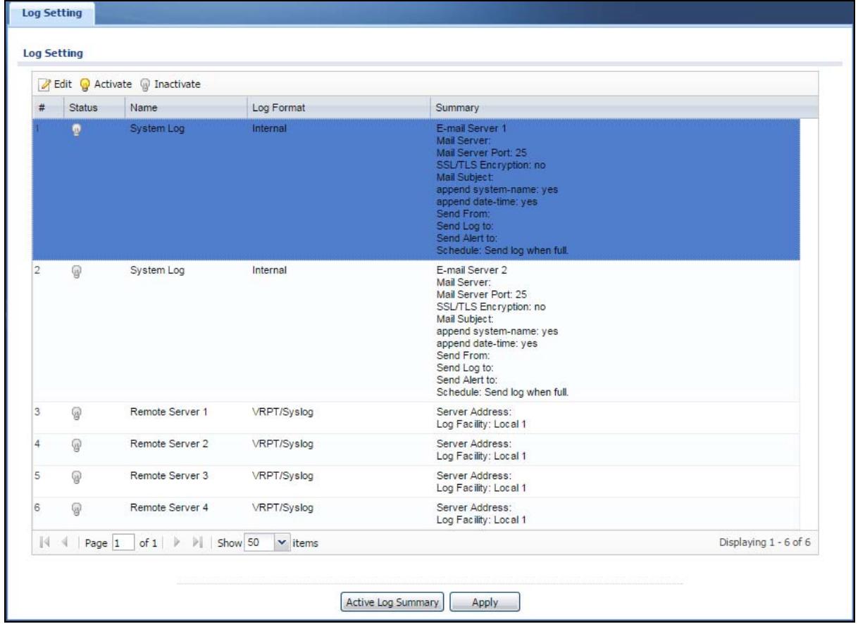
The following table describes the labels in this screen.
Table 75 Configuration > Log & Report > Log Setting
| LABEL | DESCRIPTION |
| Edit | Double-click an entry or select it and click Edit to open a screen where you can modify the entry's settings. |
| Activate | To turn on an entry, select it and click Activate. |
| Inactivate | To turn off an entry, select it and click Inactivate. |
| # | This field is a sequential value, and it is not associated with a specific log. |
| Status | This field shows whether the log is active or not. |
| Name | This field displays the name of the log (system log or one of the remote servers). |
| Log Format | This field displays the format of the log.Internal - system log; you can view the log on theView Log tab.VRPT/Syslog- Zyxel's Vantage Report, syslog-compatible format.CEF/Syslog- Common Event Format, syslog-compatible format. |
| Summary | This field is a summary of the settings for each log. |
| Active Log Summary | Click this button to open theActive Log Summaryscreen. |
| Apply | Click this button to save your changes (activate and deactivate logs) and make them take effect. |
13.3.2 Edit System Log Settings
This screen controls the detailed settings for each log in the system log (which includes the e-mail profiles). Select a system log entry in the Log Setting screen and click the Edit icon.
Figure 97 Configuration > Log & Report > Log Setting > Edit System Log Setting
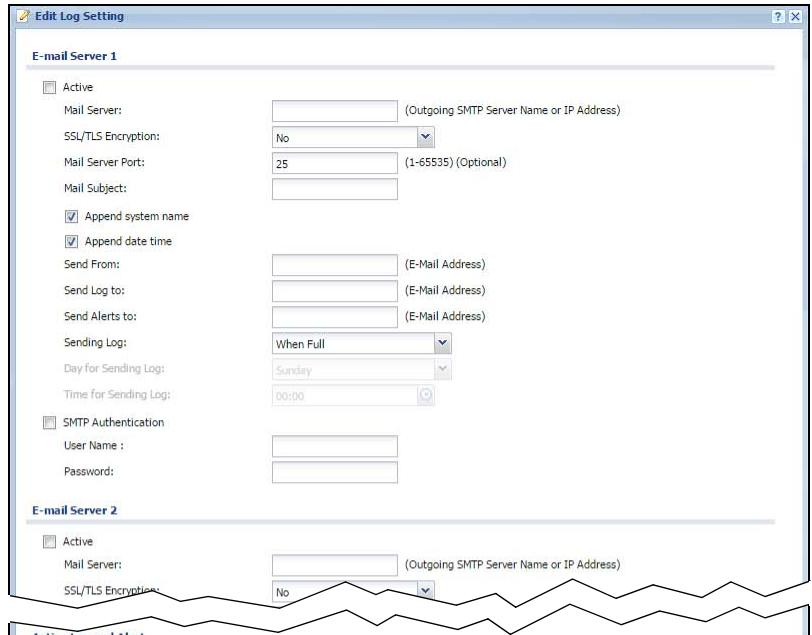
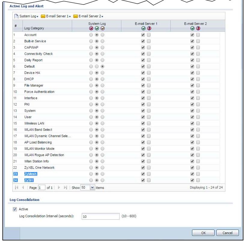
The following table describes the labels in this screen.
Table 76 Configuration > Log & Report > Log Setting > Edit System Log Setting
| LABEL | DESCRIPTION |
| E-Mail Server 1/2 | |
| Active | Select this to send log messages and alerts according to the information in this section. You specify what kinds of log messages are included in log information and what kinds of log messages are included in alerts in the Active Log and Alert section. |
| Mail Server | Type the name or IP address of the outgoing SMTP server. |
| SSL/TLS Encryption | Select SSL/TLS to use Secure Sockets Layer (SSL) or Transport Layer Security (TLS) if you want encrypted communications between the mail server and the NWA/WAC.Select STARTTLS to upgrade a plain text connection to a secure connection using SSL/TLS.Select No to not encrypt the communications. |
| Mail Server Port | Enter the same port number here as is on the mail server for mail traffic. |
| Mail Subject | Type the subject line for the outgoing e-mail. Select Append system name to add the NWA/WAC's system name to the subject. Select Append date time to add the NWA/WAC's system date and time to the subject. |
| Send From | Type the e-mail address from which the outgoing e-mail is delivered. This address is used in replies. |
| Send Log To | Type the e-mail address to which the outgoing e-mail is delivered. |
| Send Alerts To | Type the e-mail address to which alerts are delivered. |
| Sending Log | Select how often log information is e-mailed. Choices are: When Full, Hourly and When Full, Daily and When Full, and Weekly and When Full. |
| Day for Sending Log | This field is available if the log is e-mailed weekly. Select the day of the week the log is e-mailed. |
| Time for Sending Log | This field is available if the log is e-mailed weekly or daily. Select the time of day (hours and minutes) when the log is e-mailed. Use 24-hour notation. |
| SMTP Authentication | Select this check box if it is necessary to provide a user name and password to the SMTP server. |
| User Name | This box is effective when you select the SMTP Authentication check box. Type the user name to provide to the SMTP server when the log is e-mailed. |
| Password | This box is effective when you select the SMTP Authentication check box. Type the password to provide to the SMTP server when the log is e-mailed. |
| Active Log and Alert | |
| System log | Use the System Log drop-down list to change the log settings for all of the log categories.disable all logs(red X) - do not log any information for any category for the system log or e-mail any logs to e-mail server 1 or 2.enable normal logs(green check mark) - create log messages and alerts for all categories for the system log. If e-mail server 1 or 2 also has normal logs enabled, the NWA/WAC will e-mail logs to them.enable normal logs and debug logs(yellow check mark) - create log messages, alerts, and debugging information for all categories. The NWA/WAC does not e-mail debugging information, even if this setting is selected. |
| E-mail Server 1 | Use the E-Mail Server 1 drop-down list to change the settings for e-mailing logs to e-mail server 1 for all log categories.Using the System Log drop-down list to disable all logs overrides your e-mail server 1 settings.enable normal logs(green check mark) - e-mail log messages for all categories to e-mail server 1.enable alert logs(red exclamation point) - e-mail alerts for all categories to e-mail server 1. |
| E-mail Server 2 | Use the E-Mail Server 2 drop-down list to change the settings for e-mailing logs to e-mail server 2 for all log categories.Using the System Log drop-down list to disable all logs overrides your e-mail server 2 settings.enable normal logs (green check mark) - e-mail log messages for all categories to e-mail server 2.enable alert logs (red exclamation point) - e-mail alerts for all categories to e-mail server 2. |
| # | This field is a sequential value, and it is not associated with a specific address. |
| Log Category | This field displays each category of messages. It is the same value used in the Display and Category fields in the View Log tab. The Default category includes debugging messages generated by open source software. |
| System log | Select which events you want to log by Log Category. There are three choices:disable all logs (red X) - do not log any information from this categoryenable normal logs (green checkmark) - create log messages and alerts from this categoryenable normal logs and debug logs (yellow check mark) - create log messages, alerts, and debugging information from this category; the NWA/WAC does not e-mail debugging information, however, even if this setting is selected. |
| E-mail Server 1 | Select whether each category of events should be included in the log messages when it is e-mailed (green check mark) and/or in alerts (red exclamation point) for the e-mail settings specified in E-Mail Server 1. The NWA/WAC does not e-mail debugging information, even if it is recorded in the System log. |
| E-mail Server 2 | Select whether each category of events should be included in log messages when it is e-mailed (green check mark) and/or in alerts (red exclamation point) for the e-mail settings specified in E-Mail Server 2. The NWA/WAC does not e-mail debugging information, even if it is recorded in the System log. |
| Log Consolidation | |
| Active | Select this to activate log consolidation. Log consolidation aggregates multiple log messages that arrive within the specified Log Consolidation Interval. In the View Log tab, the text “[count=x]”, where x is the number of original log messages, is appended at the end of the Message field, when multiple log messages were aggregated. |
| Log Consolidation Interval | Type how often, in seconds, to consolidate log information. If the same log message appears multiple times, it is aggregated into one log message with the text “[count=x]”, where x is the number of original log messages, appended at the end of the Message field. |
| OK | Click this to save your changes and return to the previous screen. |
| Cancel | Click this to return to the previous screen without saving your changes. |
13.3.3 Edit Remote Server
This screen controls the settings for each log in the remote server (syslog). Select a remote server entry in the Log Setting screen and click the Edit icon.
Figure 98 Configuration > Log & Report > Log Setting > Edit Remote Server
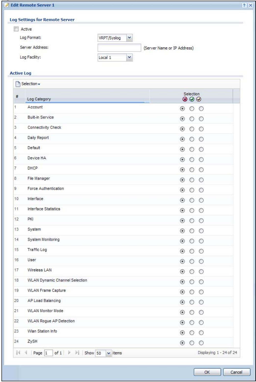
The following table describes the labels in this screen.
Table 77 Configuration > Log & Report > Log Setting > Edit Remote Server
| LABEL | DESCRIPTION |
| Log Settings for Remote Server | |
| Active | Select this check box to send log information according to the information in this section. You specify what kinds of messages are included in log information in the Active Log section. |
| Log Format | This field displays the format of the log information. It is read-only.VRPT/Syslog - Zyxel's Vantage Report, syslog-compatible format.CEF/Syslog - Common Event Format, syslog-compatible format. |
| Server Address | Type the server name or the IP address of the syslog server to which to send log information. |
| Log Facility | Select a log facility. The log facility allows you to log the messages to different files in the syslog server. Please see the documentation for your syslog program for more information. |
| Active Log | |
| Selection | Use the Selection drop-down list to change the log settings for all of the log categories.disable all logs (red X) - do not send the remote server logs for any log category.enable normal logs (green check mark) - send the remote server log messages and alerts for all log categories.enable normal logs and debug logs (yellow check mark) - send the remote server log messages, alerts, and debugging information for all log categories. |
| # | This field is a sequential value, and it is not associated with a specific address. |
| Log Category | This field displays each category of messages. It is the same value used in the Display and Category fields in the View Log tab. The Default category includes debugging messages generated by open source software. |
| Selection | Select what information you want to log from each Log Category (except All Logs; see below). Choices are:disable all logs (red X) - do not log any information from this categoryenable normal logs (green checkmark) - log regular information and alerts from this categoryenable normal logs and debug logs (yellow check mark) - log regular information, alerts, and debugging information from this category |
| OK | Click this to save your changes and return to the previous screen. |
| Cancel | Click this to return to the previous screen without saving your changes. |
13.3.4 Active Log Summary
This screen allows you to view and to edit what information is included in the system log, e-mail profiles, and remote servers at the same time. It does not let you change other log settings (for example, where and how often log information is e-mailed or remote server names). To access this screen, go to the Log Setting screen, and click the Active Log Summary button.
Figure 99 Active Log Summary
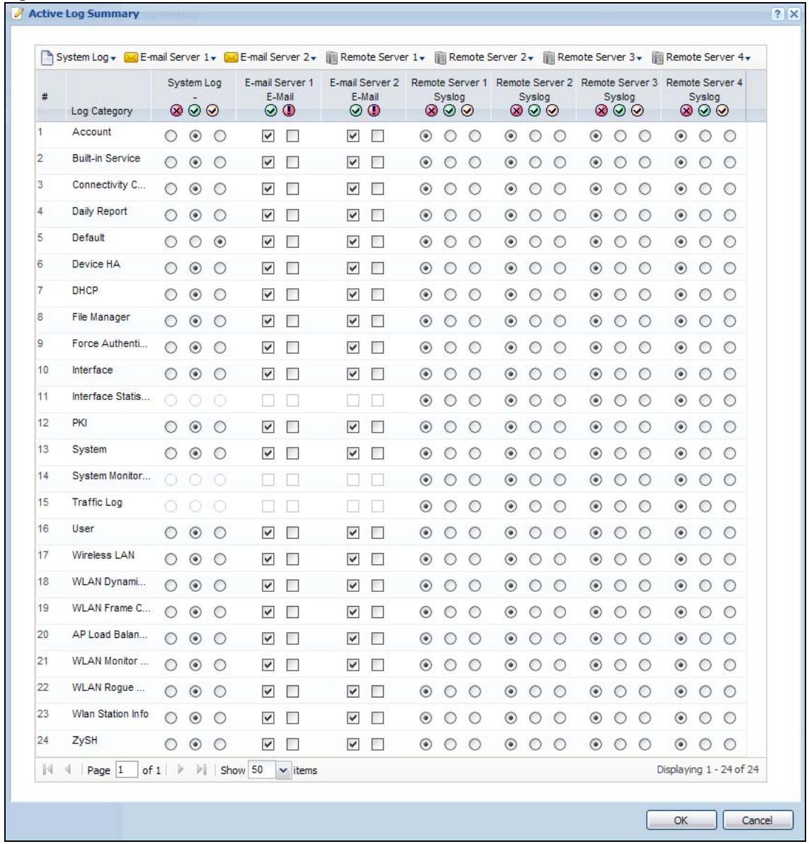
This screen provides a different view and a different way of indicating which messages are included in each log and each alert. (The Default category includes debugging messages generated by open source software.)
The following table describes the fields in this screen.
Table 78 Configuration > Log & Report > Log Setting > Active Log Summary
| LABEL | DESCRIPTION |
| Active Log Summary | If the NWA/WAC is set to controller mode, the AC section controls logs generated by the controller and the AP section controls logs generated by the managed APs. |
| System log | Use the System Log drop-down list to change the log settings for all of the log categories.disable all logs(red X) - do not log any information for any category for the system log or e-mail any logs to e-mail server 1 or 2.enable normal logs(green check mark) - create log messages and alerts for all categories for the system log. If e-mail server 1 or 2 also has normal logs enabled, the NWA/WAC will e-mail logs to them.enable normal logs and debug logs(yellow check mark) - create log messages, alerts, and debugging information for all categories. The NWA/WAC does not e-mail debugging information, even if this setting is selected. |
| E-mail Server 1 | Use the E-Mail Server 1 drop-down list to change the settings for e-mailing logs to e-mail server 1 for all log categories.Using the System Log drop-down list to disable all logs overrides your e-mail server 1 settings.enable normal logs(green check mark) - e-mail log messages for all categories to e-mail server 1.enable alert logs(red exclamation point) - e-mail alerts for all categories to e-mail server 1. |
| E-mail Server 2 | Use the E-Mail Server 2 drop-down list to change the settings for e-mailing logs to e-mail server 2 for all log categories.Using the System Log drop-down list to disable all logs overrides your e-mail server 2 settings.enable normal logs(green check mark) - e-mail log messages for all categories to e-mail server 2.enable alert logs(red exclamation point) - e-mail alerts for all categories to e-mail server 2. |
| Remote Server 1~4 | For each remote server, use the Selection drop-down list to change the log settings for all of the log categories.disable all logs(red X) - do not send the remote server logs for any log category.enable normal logs(green check mark) - send the remote server log messages and alerts for all log categories.enable normal logs and debug logs(yellow check mark) - send the remote server log messages, alerts, and debugging information for all log categories. |
| # | This field is a sequential value, and it is not associated with a specific address. |
| Log Category | This field displays each category of messages. It is the same value used in the Display and Category fields in the View Log tab. The Default category includes debugging messages generated by open source software. |
| System log | Select which events you want to log by Log Category. There are three choices:disable all logs(red X) - do not log any information from this categoryenable normal logs(green checkmark) - create log messages and alerts from this categoryenable normal logs and debug logs(yellow check mark) - create log messages, alerts, and debugging information from this category; the NWA/WAC does not e-mail debugging information, however, even if this setting is selected. |
| E-mail Server 1 E-mail | Select whether each category of events should be included in the log messages when it is e-mailed (green check mark) and/or in alerts (red exclamation point) for the e-mail settings specified in E-Mail Server 1. The NWA/WAC does not e-mail debugging information, even if it is recorded in the System log. |
| E-mail Server 2 E-mail | Select whether each category of events should be included in log messages when it is e-mailed (green check mark) and/or in alerts (red exclamation point) for the e-mail settings specified in E-Mail Server 2. The NWA/WAC does not e-mail debugging information, even if it is recorded in the System log. |
| Remote Server 1~4 Syslog | For each remote server, select what information you want to log from each Log Category (except All Logs; see below). Choices are:disable all logs(red X) - do not log any information from this categoryenable normal logs(green checkmark) - log regular information and alerts from this categoryenable normal logs and debug logs(yellow check mark) - log regular information, alerts, and debugging information from this category |
| OK | Click this to save your changes and return to the previous screen. |
| Cancel | Click this to return to the previous screen without saving your changes. |
14.1 Overview
Configuration files define the NWA/WAC's settings. Shell scripts are files of commands that you can store on the NWA/WAC and run when you need them. You can apply a configuration file or run a shell script without the NWA/WAC restarting. You can store multiple configuration files and shell script files on the NWA/WAC. You can edit configuration files or shell scripts in a text editor and upload them to the NWA/WAC. Configuration files use a .conf extension and shell scripts use a .zysh extension.
14.1.1 What You Can Do in this Chapter
- The Configuration File screen (Section 14.2 on page 170) stores and names configuration files. You can also download and upload configuration files.
- The Firmware Package screen (Section 14.3 on page 175) checks your current firmware version and uploads firmware to the NWA/WAC.
- The Shell Script screen (Section 14.4 on page 177) stores, names, downloads, uploads and runs shell script files.
14.1.2 What you Need to Know
The following terms and concepts may help as you read this chapter.
Configuration Files and Shell Scripts
When you apply a configuration file, the NWA/WAC uses the factory default settings for any features that the configuration file does not include. When you run a shell script, the NWA/WAC only applies the commands that it contains. Other settings do not change.
These files have the same syntax, which is also identical to the way you run CLI commands manually. An example is shown below.
Figure 100 Configuration File / Shell Script: Example
<h1 id="enter-configuration-mode">enter configuration mode</h1>
configure terminal
<h1 id="change-administrator-password">change administrator password</h1>
username admin password 4321 user-type admin
#configure default radio profile, change 2GHz channel to 11 & Tx output power # to 50%
wlan-radio-profile default
2g-channel 11
output-power 50%
exit
write
While configuration files and shell scripts have the same syntax, the NWA/WAC applies configuration files differently than it runs shell scripts. This is explained below.
Table 79 Configuration Files and Shell Scripts in the NWA/WAC
| Configuration Files (.conf) | Shell Scripts (.zysh) |
| Resets to default configuration.Goes into CLI Configuration mode.Runs the commands in the configuration file. | Goes into CLI Privilege mode.Runs the commands in the shell script. |
You have to run the aforementioned example as a shell script because the first command is run in Privilege mode. If you remove the first command, you have to run the example as a configuration file because the rest of the commands are executed in Configuration mode.
Comments in Configuration Files or Shell Scripts
In a configuration file or shell script, use “#” or “!” as the first character of a command line to have the NWA/WAC treat the line as a comment.
Your configuration files or shell scripts can use “exit” or a command line consisting of a single “!” to have the NWA/WAC exit sub command mode.
Note: "exit" or "!" must follow sub commands if it is to make the NWA/WAC exit sub command mode.
In the following example lines 1 and 2 are comments. Line 7 exits sub command mode.
! this is from Joe
<h1 id="on-20101205">on 2010/12/05</h1>
wlan-ssid-profile default
ssid Joe-AP
qos wmm
security default
!
Errors in Configuration Files or Shell Scripts
When you apply a configuration file or run a shell script, the NWA/WAC processes the file line-by-line. The NWA/WAC checks the first line and applies the line if no errors are detected. Then it continues with the next line. If the NWA/WAC finds an error, it stops applying the configuration file or shell script and generates a log.
You can change the way a configuration file or shell script is applied. Include setenv stop-on-error off in the configuration file or shell script. The NWA/WAC ignores any errors in the configuration file or shell script and applies all of the valid commands. The NWA/WAC still generates a log for any errors.
14.2 Configuration File
Click Maintenance > File Manager > Configuration File to open this screen. Use the Configuration File screen to store, run, and name configuration files. You can also download configuration files from the NWA/WAC to your computer and upload configuration files from your computer to the NWA/WAC.
Once your NWA/WAC is configured and functioning properly, it is highly recommended that you back up your configuration file before making further configuration changes. The backup configuration file will be useful in case you need to return to your previous settings.
Configuration File Flow at Restart
- If there is not a startup-config.conf when you restart the NWA/WAC (whether through a management interface or by physically turning the power off and back on), the NWA/WAC uses the system-default.conf configuration file with the NWA/WAC's default settings.
- If there is a startup-config.conf, the NWA/WAC checks it for errors and applies it. If there are no errors, the NWA/WAC uses it and copies it to the lastgood.conf configuration file as a back up file. If there is an error, the NWA/WAC generates a log and copies the startup-config.conf configuration file to the startup-config-bad.conf configuration file and tries the existing lastgood.conf configuration file. If there isn't a lastgood.conf configuration file or it also has an error, the NWA/WAC applies the system-default.conf configuration file.
- You can change the way the startup-config.conf file is applied. Include the setenv-startup stop-on-error off command. The NWA/WAC ignores any errors in the startup-config.conf file and applies all of the valid commands. The NWA/WAC still generates a log for any errors.
Figure 101 Maintenance > File Manager > Configuration File
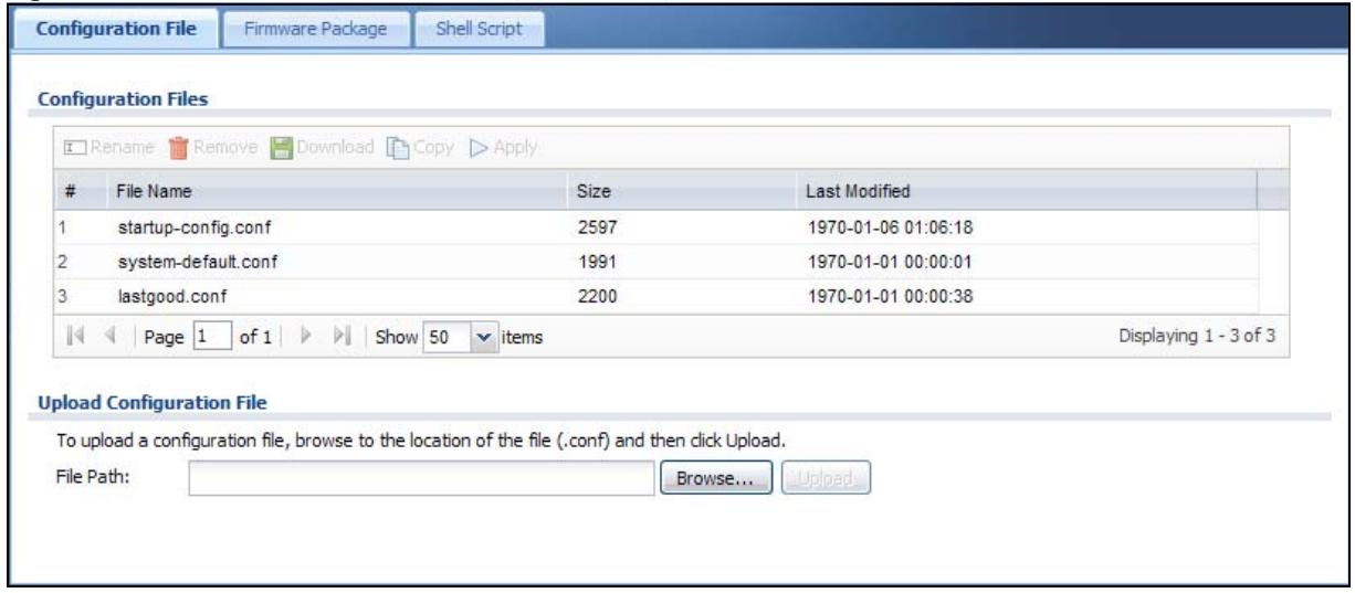
Do not turn off the NWA/WAC while configuration file upload is in progress.
The following table describes the labels in this screen.
Table 80 Maintenance > File Manager > Configuration File
| LABEL | DESCRIPTION |
| Rename | Use this button to change the label of a configuration file on the NWA/WAC. You can only rename manually saved configuration files. You cannot rename the lastgood.conf, system-default.conf and startup-config.conf files.You cannot rename a configuration file to the name of another configuration file in the NWA/WAC.Click a configuration file's row to select it and click Rename to open the Rename File screen. |
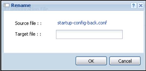 Specify the new name for the configuration file. Use up to 25 characters (including a-zA-Z0-9;‘~!@#%^&()_+[]''.=-).Click OK to save the duplicate or click Cancel to close the screen without saving a duplicate of the configuration file. Specify the new name for the configuration file. Use up to 25 characters (including a-zA-Z0-9;‘~!@#%^&()_+[]''.=-).Click OK to save the duplicate or click Cancel to close the screen without saving a duplicate of the configuration file. | |
| Remove | Click a configuration file's row to select it and click Remove to delete it from the NWA/WAC. You can only delete manually saved configuration files. You cannot delete the system-default.conf, startup-config.conf and lastgood.conf files.A pop-up window asks you to confirm that you want to delete the configuration file. Click OK to delete the configuration file or click Cancel to close the screen without deleting the configuration file. |
| Download | Click a configuration file's row to select it and click Download to save the configuration to your computer. |
| Copy | Use this button to save a duplicate of a configuration file on the NWA/WAC.Click a configuration file's row to select it and click Copy to open the Copy File screen. |
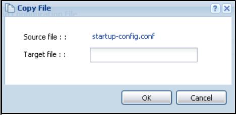 Specify a name for the duplicate configuration file. Use up to 25 characters (including a-zA-Z0-9;‘~!@#%^&()_+[]{''.=-).Click OK to save the duplicate or click Cancel to close the screen without saving a duplicate of the configuration file. Specify a name for the duplicate configuration file. Use up to 25 characters (including a-zA-Z0-9;‘~!@#%^&()_+[]{''.=-).Click OK to save the duplicate or click Cancel to close the screen without saving a duplicate of the configuration file. | |
| Apply | Use this button to have the NWA/WAC use a specific configuration file.Click a configuration file's row to select it and clickApplyto have the NWA/WAC use that configuration file. The NWA/WAC does not have to restart in order to use a different configuration file, although you will need to wait for a few minutes while the system reconfigures.The following screen gives you options for what the NWA/WAC is to do if it encounters an error in the configuration file.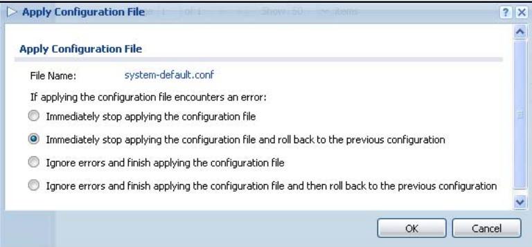 Immediately stop applying the configuration file- this is not recommended because it would leave the rest of the configuration blank. If the interfaces were not configured before the first error, the console port may be the only way to access the device.Immediately stop applying the configuration file and roll back to the previous configuration - this gets the NWA/WAC started with a fully valid configuration file as quickly as possible.Ignore errors and finish applying the configuration file- this applies the valid parts of the configuration file and generates error logs for all of the configuration file's errors. This lets the NWA/WAC apply most of your configuration and you can refer to the logs for what to fix.Ignore errors and finish applying the configuration file and then roll back to the previous configuration- this applies the valid parts of the configuration file, generates error logs for all of the configuration file's errors, and starts the NWA/WAC with a fully valid configuration file.Click OKto have the NWA/WAC start applying the configuration file or clickCancelto close the screen Immediately stop applying the configuration file- this is not recommended because it would leave the rest of the configuration blank. If the interfaces were not configured before the first error, the console port may be the only way to access the device.Immediately stop applying the configuration file and roll back to the previous configuration - this gets the NWA/WAC started with a fully valid configuration file as quickly as possible.Ignore errors and finish applying the configuration file- this applies the valid parts of the configuration file and generates error logs for all of the configuration file's errors. This lets the NWA/WAC apply most of your configuration and you can refer to the logs for what to fix.Ignore errors and finish applying the configuration file and then roll back to the previous configuration- this applies the valid parts of the configuration file, generates error logs for all of the configuration file's errors, and starts the NWA/WAC with a fully valid configuration file.Click OKto have the NWA/WAC start applying the configuration file or clickCancelto close the screen |
| # | This column displays the number for each configuration file entry. This field is a sequential value, and it is not associated with a specific address. The total number of configuration files that you can save depends on the sizes of the configuration files and the available flash storage space. |
| File Name | This column displays the label that identifies a configuration file.You cannot delete the following configuration files or change their file names.Thesystem-default.conffile contains the NWA/WAC's default settings. Select this file and clickApplyto reset all of the NWA/WAC settings to the factory defaults. This configuration file is included when you upload a firmware package.Thestartup-config.conffile is the configuration file that the NWA/WAC is currently using. If you make and save changes during your management session, the changes are applied to this configuration file. The NWA/WAC applies configuration changes made in the Web Configurator to the configuration file when you clickApplyorOK. It applies configuration changes made via commands when you use the write command.Thelastgood.confis the most recently used (valid) configuration file that was saved when the device last restarted. If you upload and apply a configuration file with an error, you can apply lastgood.conf to return to a valid configuration. |
| Size | This column displays the size (in KB) of a configuration file. |
| Last Modified | This column displays the date and time that the individual configuration files were last changed or saved. |
| Upload Configuration File | The bottom part of the screen allows you to upload a new or previously saved configuration file from your computer to your NWA/WACYou cannot upload a configuration file named system-default.conf or lastgood.conf.If you upload startup-config.conf, it will replace the current configuration and immediately apply the new settings. |
| File Path | Type in the location of the file you want to upload in this field or click Browse... to find it. |
| Browse... | Click Browse... to find the .conf file you want to upload. The configuration file must use a “.conf” filename extension. You will receive an error message if you try to upload a fie of a different format. Remember that you must decompress compressed (.zip) files before you can upload them. |
| Upload | Click Upload to begin the upload process. This process may take up to two minutes. |
14.2.1 Example of Configuration File Download Using FTP
The following example gets a configuration file named startup-config.conf from the NWA/WAC and saves it on the computer.
1 Connect your computer to the NWA/WAC.
2 The FTP server IP address of the NWA/WAC in standalone AP mode is 192.168.1.2, so set your computer to use a static IP address from 192.168.1.3 \~ 192.168.1.254.
3 Use an FTP client on your computer to connect to the NWA/WAC. For example, in the Windows command prompt, type ftp 192.168.1.2. Keep the console session connected in order to see when the firmware recovery finishes.
4 Enter your user name when prompted.
5 Enter your password as requested.
6 Use "cd" to change to the directory that contains the files you want to download.
7 Use "dir" or "ls" if you need to display a list of the files in the directory.
8 Use "get" to download files. Transfer the configuration file on the NWA/WAC to your computer. Type get followed by the name of the configuration file. This examples uses get startup-config.conf.
C:\>ftp 192.168.1.2
Connected to 192.168.1.2.
220---- Welcome to Pure-FTPd [privsep] [TLS] ----
220-You are user number 1 of 5 allowed.
220-Local time is now 21:28. Server port: 21.
220-This is a private system - No anonymous login
220 You will be disconnected after 600 minutes of inactivity.
User (192.168.1.2:(none)): admin
331 User admin OK. Password required
Password:
230 OK. Current restricted directory is /
ftp> cd conf
250 OK. Current directory is /conf
ftp> ls
200 PORT command successful
150 Connecting to port 5001
lastgood.conf
startup-config.conf
system-default.conf
226 3 matches total
ftp: 57 bytes received in 0.33Seconds 0.17Kbytes/sec.
ftp> get startup-config.conf
200 PORT command successful
150 Connecting to port 5002
226-File successfully transferred
226 0.002 seconds (measured here), 1.66 Mbytes per second
ftp: 2928 bytes received in 0.02Seconds 183.00Kbytes/sec.
ftp>
9 Wait for the file transfer to complete.
10 Enter "quit" to exit the ftp prompt.
14.3 Firmware Package
Click Maintenance > File Manager > Firmware Package to open this screen. Use the Firmware Package screen to check your current firmware version and upload firmware to the NWA/WAC.
Note: The Web Configurator is the recommended method for uploading firmware. You only need to use the command line interface if you need to recover the firmware. See the CLI Reference Guide for how to determine if you need to recover the firmware and how to recover it.
Find the firmware package at www.zyxel.com in a file that (usually) uses a .bin extension.
The firmware update can take up to five minutes. Do not turn off or reset the NWA/WAC while the firmware update is in progress!
Figure 102 Maintenance > File Manager > Firmware Package
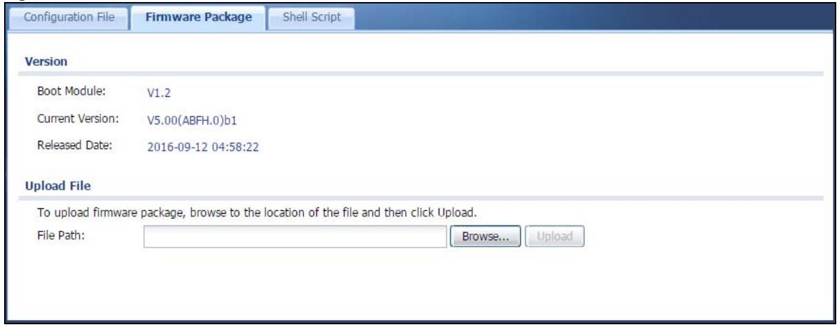
The following table describes the labels in this screen.
Table 81 Maintenance > File Manager > Firmware Package
| LABEL | DESCRIPTION |
| Boot Module | This is the version of the boot module that is currently on the NWA/WAC. |
| Current Version | This is the firmware version and the date created. |
| Released Date | This is the date that the version of the firmware was created. |
| File Path | Type in the location of the file you want to upload in this field or click Browse... to find it. |
| Browse... | Click Browse... to find the .bin file you want to upload. Remember that you must decompress compressed (.zip) files before you can upload them. |
| Upload | Click Upload to begin the upload process. This process may take up to two minutes. |
After you see the Firmware Upload in Process screen, wait two minutes before logging into the NWA/WAC again.
Note: The NWA/WAC automatically reboots after a successful upload.
The NWA/WAC automatically restarts causing a temporary network disconnect. In some operating systems, you may see the following icon on your desktop.
Figure 103 Network Temporarily Disconnected
After five minutes, log in again and check your new firmware version in the Dashboard screen.
14.3.1 Example of Firmware Upload Using FTP
This procedure requires the NWA/WAC's firmware. Download the firmware package from www.zyxel.com and unzip it. The firmware file uses a .bin extension, for example, "420AAHY1C0.bin". Do the following after you have obtained the firmware file.
1 Connect your computer to the NWA/WAC.
2 The FTP server IP address of the NWA/WAC in standalone AP mode is 192.168.1.2, so set your computer to use a static IP address from 192.168.1.3 \~ 192.168.1.254.
3 Use an FTP client on your computer to connect to the NWA/WAC. For example, in the Windows command prompt, type ftp 192.168.1.2. Keep the console session connected in order to see when the firmware recovery finishes.
4 Enter your user name when prompted.
5 Enter your password as requested.
6 Enter "hash" for FTP to print a `#` character for every 1024 bytes of data you upload so that you can watch the file transfer progress.
7 Enter "bin" to set the transfer mode to binary.
8 Transfer the firmware file from your computer to the NWA/WAC. Type put followed by the path and name of the firmware file. This examples uses put C:\ftproot\NWA/WAC_FW\500ABFH0C0.bin.
C:\>ftp 192.168.1.2
Connected to 192.168.1.2.
220---- Welcome to Pure-FTPd [privsep] [TLS] ----
220-You are user number 1 of 5 allowed.
220-Local time is now 21:28. Server port: 21.
220-This is a private system - No anonymous login
220 You will be disconnected after 600 minutes of inactivity.
User (192.168.1.2:(none)): admin
331 User admin OK. Password required
Password:
230 OK. Current restricted directory is /
ftp> hash
Hash mark printing On ftp: (2048 bytes/hash mark) .
ftp> bin
200 TYPE is now 8-bit binary
ftp> put C:\ftproot\NWA/WAC_FW\500ABFH0C0.bin
9 Wait for the file transfer to complete.
10 Enter "quit" to exit the ftp prompt.
14.4 Shell Script
Use shell script files to have the NWA/WAC use commands that you specify. Use a text editor to create the shell script files. They must use a “.zysh” filename extension.
Click Maintenance > File Manager > Shell Script to open this screen. Use the Shell Script screen to store, name, download, upload and run shell script files. You can store multiple shell script files on the NWA/WAC at the same time.
Note: You should include write commands in your scripts. If you do not use the write command, the changes will be lost when the NWA/WAC restarts. You could use multiple write commands in a long script.
Figure 104 Maintenance > File Manager > Shell Script
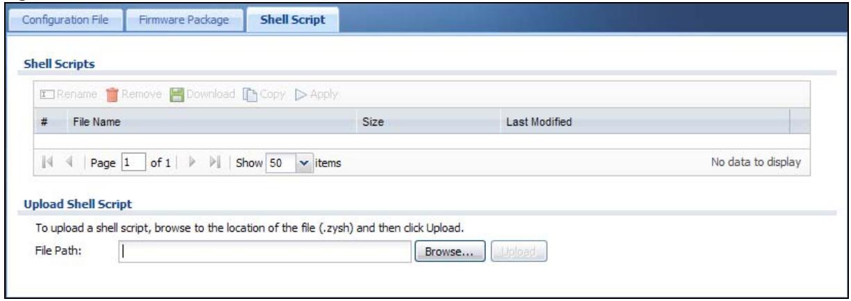
Each field is described in the following table.
Table 82 Maintenance > File Manager > Shell Script
| LABEL | DESCRIPTION |
| Rename | Use this button to change the label of a shell script file on the NWA/WAC.You cannot rename a shell script to the name of another shell script in the NWA/WAC.Click a shell script's row to select it and clickRename to open theRename Filescreen.Specify the new name for the shell script file. Use up to 25 characters (including a-zA-Z0-9;‘~!@#%^&()_+[]'.',=-).ClickOKto save the duplicate or clickCancelto close the screen without saving a duplicate of the configuration file. |
| Remove | Click a shell script file's row to select it and clickDeleteto delete the shell script file from the NWA/WAC.A pop-up window asks you to confirm that you want to delete the shell script file. Click OKto delete the shell script file or clickCancelto close the screen without deleting the shell script file. |
| Download | Click a shell script file's row to select it and clickDownloadto save the configuration to your computer. |
| Copy | Use this button to save a duplicate of a shell script file on the NWA/WAC.Click a shell script file's row to select it and clickCopyto open theCopy Filescreen.Specify a name for the duplicate file. Use up to 25 characters (including a-zA-Z0-9;‘~!@#%^&()_+[]{'.',=-).ClickOKto save the duplicate or clickCancelto close the screen without saving a duplicate of the configuration file. |
| Run | Use this button to have the NWA/WAC use a specific shell script file.Click a shell script file's row to select it and clickRunto have the NWA/WAC use that shell script file. You may need to wait awhile for the NWA/WAC to finish applying the commands. |
| # | This column displays the number for each shell script file entry. |
| File Name | This column displays the label that identifies a shell script file. |
| Size | This column displays the size (in KB) of a shell script file. |
| Last Modified | This column displays the date and time that the individual shell script files were last changed or saved. |
| Upload Shell Script | The bottom part of the screen allows you to upload a new or previously saved shell script file from your computer to your NWA/WAC. |
| File Path | Type in the location of the file you want to upload in this field or click Browse... to find it. |
| Browse... | Click Browse... to find the .zysh file you want to upload. |
| Upload | Click Upload to begin the upload process. This process may take up to several minutes. |
CHAPTER 15 Diagnostics
15.1 Overview
Use the diagnostics screen for troubleshooting.
15.1.1 What You Can Do in this Chapter
- The Diagnostics screen (Section 15.2 on page 180) generates a file containing the NWA/WAC's configuration and diagnostic information if you need to provide it to customer support during troubleshooting.
15.2 Diagnostics
This screen provides an easy way for you to generate a file containing the NWA/WAC's configuration and diagnostic information. You may need to generate this file and send it to customer support during troubleshooting.
Click Maintenance > Diagnostics to open the Diagnostic screen.
Figure 105 Maintenance > Diagnostics
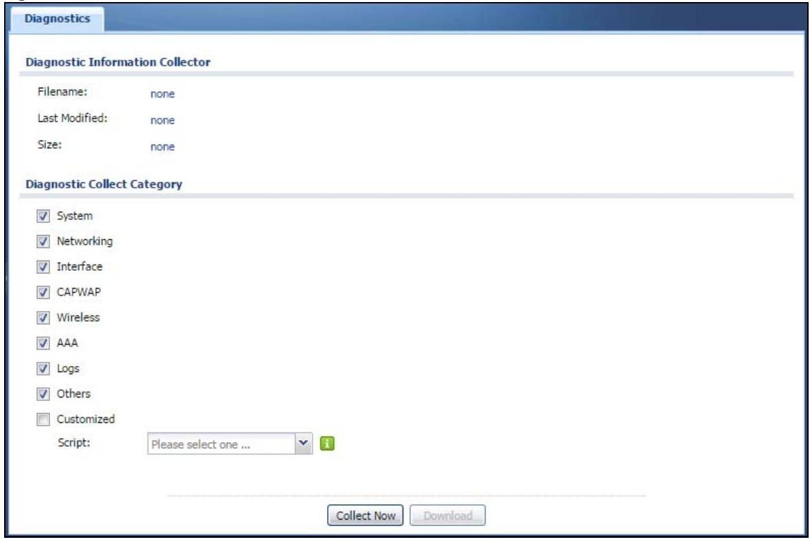
The following table describes the labels in this screen.
Table 83 Maintenance > Diagnostics
| LABEL | DESCRIPTION |
| Filename | This is the name of the most recently created diagnostic file. |
| Last modified | This is the date and time that the last diagnostic file was created. The format is yyyy-mm-dd hh:mm:ss. |
| Size | This is the size of the most recently created diagnostic file. |
| Diagnostic Collect Category | This field displays each category of settings. Select which categories you want the NWA/WAC to include in the diagnostic file. |
| Customized | Select this option to obtain the diagnostic information for configuration which is not included in a pre-defined category. |
| Script | If you select the Customized option, select a shell script file from the drop-down list. You can upload a new shell script file using the Maintenance > File Manager > Shell Script screen. |
| Collect Now | Click this to have the NWA/WAC create a new diagnostic file. |
| Download | Click this to save the most recent diagnostic file to a computer. |
16.1 Overview
The LEDs of your NWA/WAC can be controlled such that they stay lit (ON) or OFF after the NWA/WAC is ready. There are two features that control the LEDs of your NWA/WAC - Locator and Suppression.
16.1.1 What You Can Do in this Chapter
- The Suppression screen (Section 16.2 on page 182)) allows you to set how you want the LEDs to behave after the device is ready.
- The Locator screen (Section 16.3 on page 183) allows users to see the actual location of the NWA/WAC between several devices in the network.
16.2 Suppression Screen
The LED Suppression feature allows you to control how the LEDs of your NWA/WAC behave after it's ready. The default LED suppression setting of your AP is different depending on your NWA/WAC model.
You can go to the Maintenance > LEDs > Suppression screen to see the default LED behavior and change the LED suppression setting. After you make changes in the suppression screen, it will be stored as the default when the NWA/WAC is restarted. See (Section 1.6 on page 20) for information on default values for different models.
Note: When the NWA/WAC is booting or performing firmware upgrade, the LEDs will lit regardless of the setting in LED suppression.
To access this screen, click Maintenance > LEDs > Suppression.
Figure 106 Maintenance > LEDs > Suppression
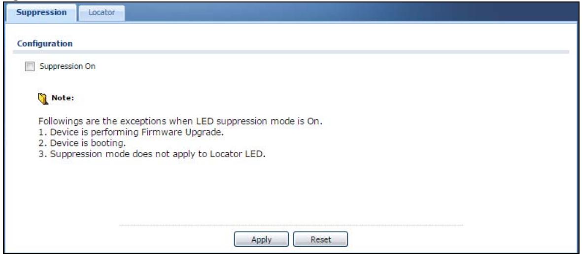
The following table describes fields in the above screen.
Table 84 Maintenance > LED > Suppression
| LABEL | DESCRIPTION |
| Suppression On | If the Suppression On check box is checked, the LEDs of your NWA/WAC will turn off after it's ready.If the check box is unchecked, the LEDs will stay lit after the NWA/WAC is ready. |
| Apply | Click Apply to save your changes back to the NWA/WAC. |
| Reset | Click Reset to return the screen to its last-saved settings. |
16.3 Locator Screen
The Locator feature identifies the location of your WAC among several devices in the network. You can run this feature and set a timer in this screen.
To run the locator feature, enter a number of minutes and click Turn On button to have the WAC find its location. The Locator LED will start to blink for the number of minutes set in the Locator screen. The default setting is 10 minutes. While the locator is running, the turn on button will grey out and return after it's finished. If you make changes to the time default setting, it will be stored as the default when the WAC restarts.
Note: The Locator feature is not affected by the Suppression setting.
To access this screen, click Maintenance > LEDs > Locator.
Figure 107 Maintenance > LEDs > Locator
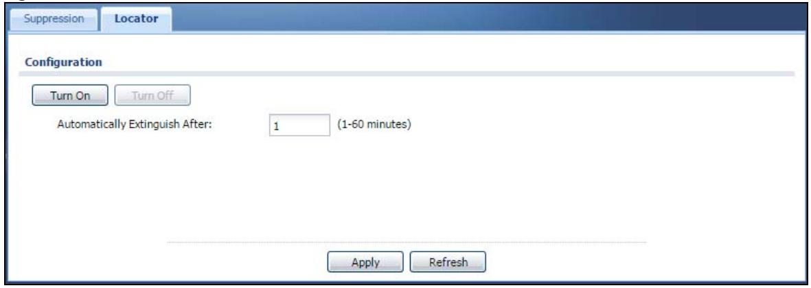
The following table describes fields in the above screen.
Table 85 Maintenance > LED > Locator
| LABEL | DESCRIPTION |
| Turn OnTurn Off | Click Turn On button to activate the locator. The Locator function will show the actual location of the WAC between several devices in the network.Otherwise, click Turn Off to disable the locator feature. |
| Automatically Extinguish After | Enter a time interval between 1 and 60 minutes to stop the locator LED from blinking. Default is 10 minutes. |
| Apply | Click Apply to save changes in this screen. |
| Refresh | Click Refresh to update the information in this screen. |
CHAPTER 17
Antenna Switch
17.1 Overview
Use this screen to adjust coverage depending on the orientation of the antenna.
17.1.1 What You Need To Know
Positioning the antennas properly increases the range and coverage area of a wireless LAN.
On the NWA/WAC that comes with internal antennas and also has an antenna switch, you can adjust coverage depending on the orientation of the antenna for the NWA/WAC radios using the web configurator, the command line interface (CLI) or a physical switch. Check Table 1 on page 11 and Table 2 on page 12 to see if your NWA/WAC has an antenna switch.
Figure 108 WAC6103D-I Physical Antenna Switch
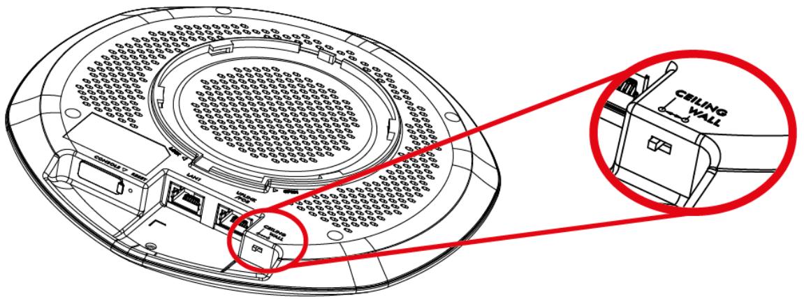
Note: With the physical antenna switch, you apply the same antenna orientation settings to both radios. You can set the radios to have different settings while using the web configurator or the command line interface.
Note: The antenna switch in the web configurator has priority over the physical antenna switch after you Enable Software Control in the Maintenance > Antenna screen. By default, software control is disabled.
17.2 Antenna Switch Screen
To access this screen, click Maintenance > Antenna.
Figure 109 Maintenance > Antenna > Antenna Switch
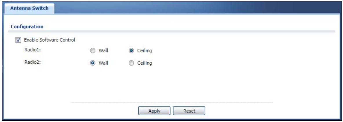
Select the Enable Software Control option to use the Web configurator to adjust coverage depending on each radio's antenna orientation for better coverage. Select Wall if you mount the NWA/WAC to a wall. Select Ceiling if the the NWA/WAC is mounted on a ceiling. You can switch from Wall to Ceiling if there are still wireless dead zones, and vice versa.
CHAPTER 18 Reboot
18.1 Overview
Use this screen to restart the device.
18.1.1 What You Need To Know
If you applied changes in the Web configurator, these were saved automatically and do not change when you reboot. If you made changes in the CLI, however, you have to use the write command to save the configuration before you reboot. Otherwise, the changes are lost when you reboot.
Reboot is different to reset; reset returns the device to its default configuration.
18.2 Reboot
This screen allows remote users can restart the device. To access this screen, click Maintenance > Reboot.
Figure 110 Maintenance > Reboot
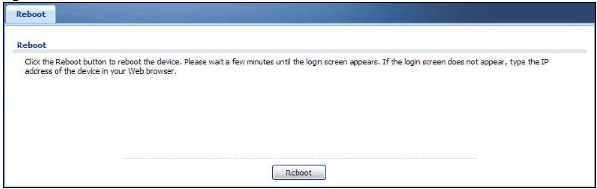
Click the Reboot button to restart the NWA/WAC. Wait a few minutes until the login screen appears. If the login screen does not appear, type the IP address of the device in your Web browser.
You can also use the CLI command reboot to restart the NWA/WAC.
CHAPTER 19 Shutdown
19.1 Overview
Use this screen to shut down the device.
Always use Maintenance > Shutdown > Shutdown or the shutdown command before you turn off the NWA/WAC or remove the power. Not doing so can cause the firmware to become corrupt.
19.1.1 What You Need To Know
Shutdown writes all cached data to the local storage and stops the system processes. Shutdown is different to reset; reset returns the device to its default configuration.
19.2 Shutdown
To access this screen, click Maintenance > Shutdown.
Figure 111 Maintenance > Shutdown
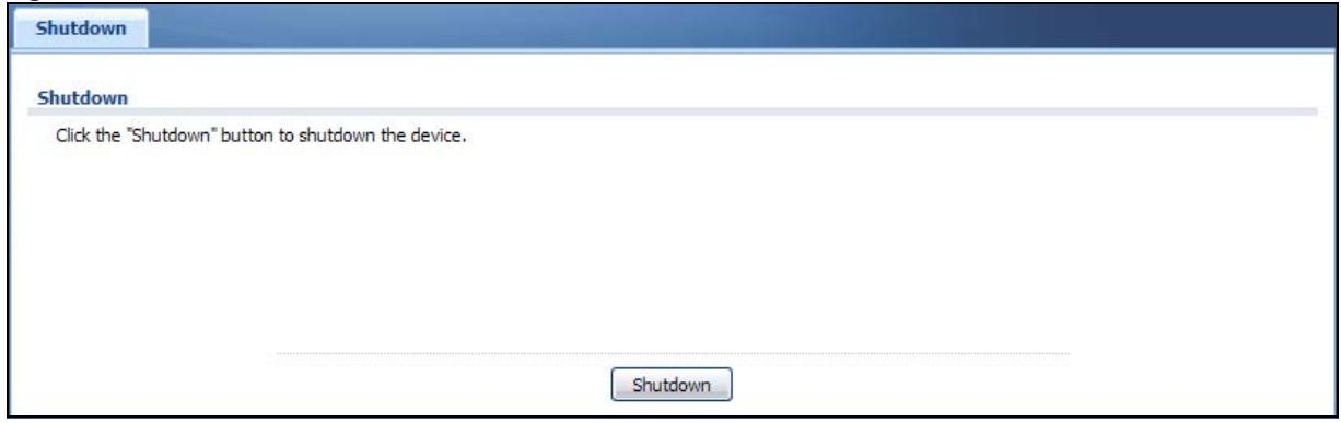
Click the Shutdown button to shut down the NWA/WAC. Wait for the device to shut down before you manually turn off or remove the power. It does not turn off the power.
You can also use the CLI command shutdown to shut down the NWA/WAC.
20.1 Overview
This chapter offers some suggestions to solve problems you might encounter. The potential problems are divided into the following categories.
• Power, Hardware Connections, and LED
• NWA/WAC Access and Login
- Internet Access
- Wireless Connections
- Resetting the NWA/WAC
20.2 Power, Hardware Connections, and LED
The NWA/WAC does not turn on. The LED is not on.
1 Make sure you are using the power adaptor included with the NWA/WAC or a PoE power injector/ switch.
2 Make sure the power adaptor or PoE power injector/switch is connected to the NWA/WAC and plugged in to an appropriate power source. Make sure the power source is turned on.
3 Disconnect and re-connect the power adaptor or PoE power injector/switch.
4 Inspect your cables for damage. Contact the vendor to replace any damaged cables.
5 If none of these steps work, you may have faulty hardware and should contact your NWA/WAC vendor.
The LED does not behave as expected.
1 Make sure you understand the normal behavior of the LED. See Section 1.6 on page 20.
2 Check the hardware connections. See the Quick Start Guide.
3 Inspect your cables for damage. Contact the vendor to replace any damaged cables.
4 Disconnect and re-connect the power adaptor or PoE power injector to the NWA/WAC.
5 If the problem continues, contact the vendor.
20.3 NWA/WAC Access and Login
I forgot the IP address for the NWA/WAC.
1 The default IP address (in standalone AP mode) is 192.168.1.2.
2 If you changed the IP address and have forgotten it, you have to reset the device to its factory defaults. See Section 20.6 on page 197.
3 If your NWA/WAC is a DHCP client, you can find your IP address from the DHCP server. This information is only available from the DHCP server which allocates IP addresses on your network. Find this information directly from the DHCP server or contact your system administrator for more information.
I cannot see or access the Login screen in the web configurator.
1 Make sure you are using the correct IP address.
- The default IP address (in standalone AP mode) is 192.168.1.2.
- If you changed the IP address, use the new IP address.
- If you changed the IP address and have forgotten it, see the troubleshooting suggestions for I forgot the IP address for the NWA/WAC.
2 Check the hardware connections, and make sure the LED is behaving as expected. See the Quick Start Guide and Section 1.6 on page 20.
3 Make sure your Internet browser does not block pop-up windows and has JavaScripts and Java enabled.
4 Make sure your computer is in the same subnet as the NWA/WAC. (If you know that there are routers between your computer and the NWA/WAC, skip this step.)
- If there is a DHCP server on your network, make sure your computer is using a dynamic IP address.
- If there is no DHCP server on your network, make sure your computer's IP address is in the same subnet as the NWA/WAC.
5 Reset the device to its factory defaults, and try to access the NWA/WAC with the default IP address. See Section 20.6 on page 197.
6 If the problem continues, contact the network administrator or vendor, or try one of the advanced suggestions.
Advanced Suggestions
- Try to access the NWA/WAC using another service, such as Telnet. If you can access the NWA/WAC, check the remote management settings to find out why the NWA/WAC does not respond to HTTP.
- If your computer is connected wirelessly, use a computer that is connected to a LAN/ETHERNET port.
I forgot the password.
1 The default password is 1234.
2 If this does not work, you have to reset the device to its factory defaults. See Section 20.6 on page 197.
I can see the Login screen, but I cannot log in to the NWA/WAC.
1 Make sure you have entered the user name and password correctly. The default password is 1234. This fields are case-sensitive, so make sure [Caps Lock] is not on.
2 You cannot log in to the web configurator while someone is using Telnet to access the NWA/WAC. Log out of the NWA/WAC in the other session, or ask the person who is logged in to log out.
3 Disconnect and re-connect the power adaptor or PoE power injector to the NWA/WAC.
4 If this does not work, you have to reset the device to its factory defaults. See Section 20.6 on page 197.
I cannot use FTP to upload / download the configuration file. / I cannot use FTP to upload new firmware.
See the troubleshooting suggestions for I cannot see or access the Login screen in the web configurator. Ignore the suggestions about your browser.
20.4 Internet Access
I cannot access the Internet.
1 Check the hardware connections, and make sure the LED is behaving as expected. See the Quick Start Guide and Section 20.2 on page 189.
2 Make sure the NWA/WAC is connected to a broadband modem or router with Internet access and your computer is set to obtain an dynamic IP address.
3 If you are trying to access the Internet wirelessly, make sure the wireless settings on the wireless client are the same as the settings on the NWA/WAC.
4 Disconnect all the cables from your device, and follow the directions in the Quick Start Guide again.
5 If the problem continues, contact your ISP.
I cannot access the Internet anymore. I had access to the Internet (with the NWA/WAC), but my Internet connection is not available anymore.
1 Check the hardware connections, and make sure the LED is behaving as expected. See the Quick Start Guide and Section 1.6 on page 20.
2 Reboot the NWA/WAC.
3 If the problem continues, contact your ISP.
The Internet connection is slow or intermittent.
1 There might be a lot of traffic on the network. Look at the LED, and check Section 1.6 on page 20. If the NWA/WAC is sending or receiving a lot of information, try closing some programs that use the Internet, especially peer-to-peer applications.
2 Check the signal strength. If the signal is weak, try moving the NWA/WAC closer to the NWA/WAC (if possible), and look around to see if there are any devices that might be interfering with the wireless network (microwaves, other wireless networks, and so on).
3 Reboot the NWA/WAC.
4 If the problem continues, contact the network administrator or vendor, or try one of the advanced suggestions.
Advanced Suggestions
Check the settings for QoS. If it is disabled, you might consider activating it. If it is enabled, you might consider raising or lowering the priority for some applications.
20.5 Wireless Connections
I cannot access the NWA/WAC or ping any computer from the WLAN.
1 Make sure the wireless LAN (wireless radio) is enabled on the NWA/WAC.
2 Make sure the radio or at least one of the NWA/WAC's radios is operating in AP mode.
3 Make sure the wireless adapter (installed on your computer) is working properly.
4 Make sure the wireless adapter (installed on your computer) is IEEE 802.11 compatible and supports the same wireless standard as the NWA/WAC's active radio.
5 Make sure your computer (with a wireless adapter installed) is within the transmission range of the NWA/WAC.
6 Check that both the NWA/WAC and your computer are using the same wireless and wireless security settings.
Hackers have accessed my WEP-encrypted wireless LAN.
WEP is extremely insecure. Its encryption can be broken by an attacker, using widely-available software. It is strongly recommended that you use a more effective security mechanism. Use the strongest security mechanism that all the wireless devices in your network support. WPA2 or WPA2-PSK is recommended.
The wireless security is not following the re-authentication timer setting I specified.
If a RADIUS server authenticates wireless stations, the re-authentication timer on the RADIUS server has priority. Change the RADIUS server's configuration if you need to use a different re-authentication timer setting.
I cannot get a certificate to import into the NWA/WAC.
1 For My Certificates, you can import a certificate that matches a corresponding certification request that was generated by the NWA/WAC. You can also import a certificate in PKCS#12 format, including the certificate's public and private keys.
2 You must remove any spaces from the certificate's filename before you can import the certificate.
3 Any certificate that you want to import has to be in one of these file formats:
- Binary X.509: This is an ITU-T recommendation that defines the formats for X.509 certificates.
- PEM (Base-64) encoded X.509: This Privacy Enhanced Mail format uses lowercase letters, uppercase letters and numerals to convert a binary X.509 certificate into a printable form.
- Binary PKCS#7: This is a standard that defines the general syntax for data (including digital signatures) that may be encrypted. A PKCS #7 file is used to transfer a public key certificate. The private key is not included. The NWA/WAC currently allows the importation of a PKS#7 file that contains a single certificate.
- PEM (Base-64) encoded PKCS#7: This Privacy Enhanced Mail (PEM) format uses lowercase letters, uppercase letters and numerals to convert a binary PKCS#7 certificate into a printable form.
- Binary PKCS#12: This is a format for transferring public key and private key certificates. The private key in a PKCS #12 file is within a password-encrypted envelope. The file's password is not connected to your certificate's public or private passwords. Exporting a PKCS #12 file creates this and you must provide it to decrypt the contents when you import the file into the NWA/WAC.
Note: Be careful not to convert a binary file to text during the transfer process. It is easy for this to occur since many programs use text files by default.
I can only see newer logs. Older logs are missing.
When a log reaches the maximum number of log messages, new log messages automatically overwrite existing log messages, starting with the oldest existing log message first.
The commands in my configuration file or shell script are not working properly.
- In a configuration file or shell script, use “#” or “!” as the first character of a command line to have the NWA/WAC treat the line as a comment.
- Your configuration files or shell scripts can use "exit" or a command line consisting of a single "!" to have the NWA/WAC exit sub command mode.
- Include write commands in your scripts. Otherwise the changes will be lost when the NWA/WAC restarts. You could use multiple write commands in a long script.
Note: "exit" or "!" must follow sub commands if it is to make the NWA/WAC exit sub command mode.
I cannot get the firmware uploaded using the commands.
The Web Configurator is the recommended method for uploading firmware. You only need to use the command line interface if you need to recover the firmware. See the CLI Reference Guide for how to determine if you need to recover the firmware and how to recover it.
Wireless clients are not being load balanced among my APs.
- Make sure that all the APs used by the wireless clients in question share the same SSID, security, and radio settings.
- Make sure that all the APs are in the same broadcast domain.
- Make sure that the wireless clients are in range of the other APs; if they are only in range of a single AP, then load balancing may not be as effective.
In the Monitor > Wireless > AP Information > Radio List screen, there is no load balancing indicator associated with any APs assigned to the load balancing task.
- Check to be sure that the AP profile which contains the load balancing settings is correctly assigned to the APs in question.
- The load balancing task may have been terminated because further load balancing on the APs in question is no longer required.
How do I remove the WAC6500 series indoor AP from its mounting bracket?
- Find the down arrow close to the Ethernet ports, then use a thin flat tool (for example, a flat screw driver) to lift up a clip beneath the down arrow.
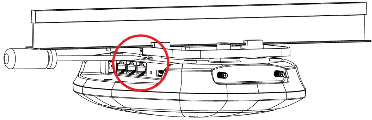
natural_image
Technical line drawing of a tank with a red circle highlighting a component (no text or symbols present)- Turn the WAC6500 series indoor AP counter-clockwise.
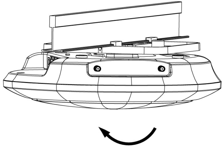
natural_image
Technical line drawing of a mechanical device with a curved arrow indicating rotation or motion (no text or symbols present)- Detach the WAC6500 series indoor AP from the mounting bracket.
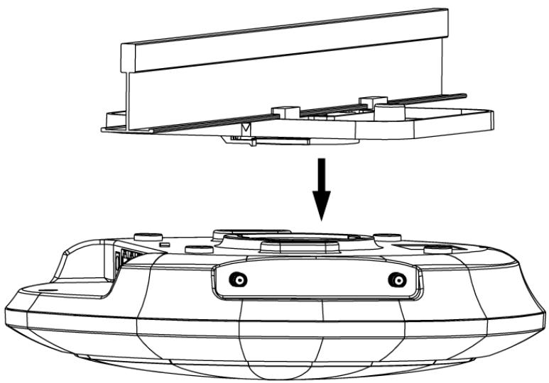
natural_image
Technical line drawing of a mechanical assembly with a downward arrow indicating assembly or transformation (no text or symbols present)How do I remove the NWA1123-AC PRO and WAC6103D-I indoor AP from its mounting bracket?
- Find the down arrow close to the Ethernet ports, then use a thin flat tool (for example, a flat screw driver) to lift up a clip beneath 5GHz LED.
- Turn the NWA1123-AC PRO or WAC6103D-I indoor AP counter-clockwise to detach it from the mounting bracket.
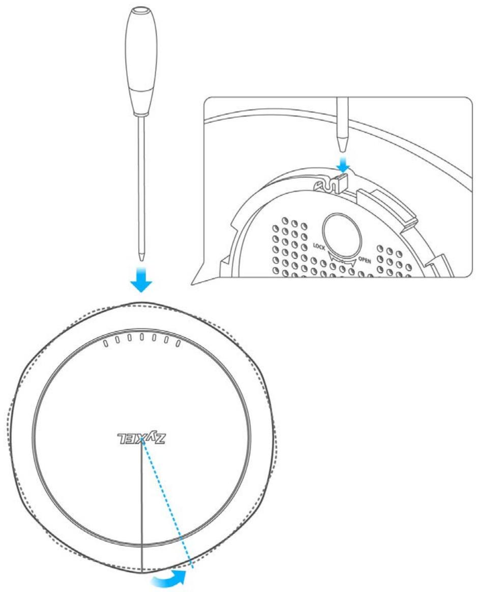
20.6 Resetting the NWA/WAC
If you cannot access the NWA/WAC by any method, try restarting it by turning the power off and then on again. If you still cannot access the NWA/WAC by any method or you forget the administrator password(s), you can reset the NWA/WAC to its factory-default settings. Any configuration files or shell scripts that you saved on the NWA/WAC should still be available afterwards.
Use the following procedure to reset the NWA/WAC to its factory-default settings. This overwrites the settings in the startup-config.conf file with the settings in the system-default.conf file.
Note: This procedure removes the current configuration.
1 Make sure the Power LED is on and not blinking.
2 Press the RESET button and hold it until the Power LED begins to blink. (This usually takes about ten seconds.)
3 Release the RESET button, and wait for the NWA/WAC to restart.
You should be able to access the NWA/WAC using the default settings.
20.7 Getting More Troubleshooting Help
Search for support information for your model at www.zyxel.com for more troubleshooting suggestions.
APPENDIX A
Importing Certificates
This appendix shows you how to import public key certificates into your web browser.
Public key certificates are used by web browsers to ensure that a secure web site is legitimate. When a certificate authority such as VeriSign, Comodo, or Network Solutions, to name a few, receives a certificate request from a website operator, they confirm that the web domain and contact information in the request match those on public record with a domain name registrar. If they match, then the certificate is issued to the website operator, who then places it on the site to be issued to all visiting web browsers to let them know that the site is legitimate.
Many Zyxel products, such as the NWA/WAC, issue their own public key certificates. These can be used by web browsers on a LAN or WAN to verify that they are in fact connecting to the legitimate device and not one masquerading as it. However, because the certificates were not issued by one of the several organizations officially recognized by the most common web browsers, you will need to import the Zyxel-created certificate into your web browser and flag that certificate as a trusted authority.
Note: You can see if you are browsing on a secure website if the URL in your web browser's address bar begins with https:// or there is a sealed padlock icon ( ) somewhere in the main browser window (not all browsers show the padlock in the same location).
Internet Explorer
The following example uses Microsoft Internet Explorer 7 on Windows XP Professional; however, they can also apply to Internet Explorer on Windows Vista.
1 If your device's Web Configurator is set to use SSL certification, then the first time you browse to it you are presented with a certification error.
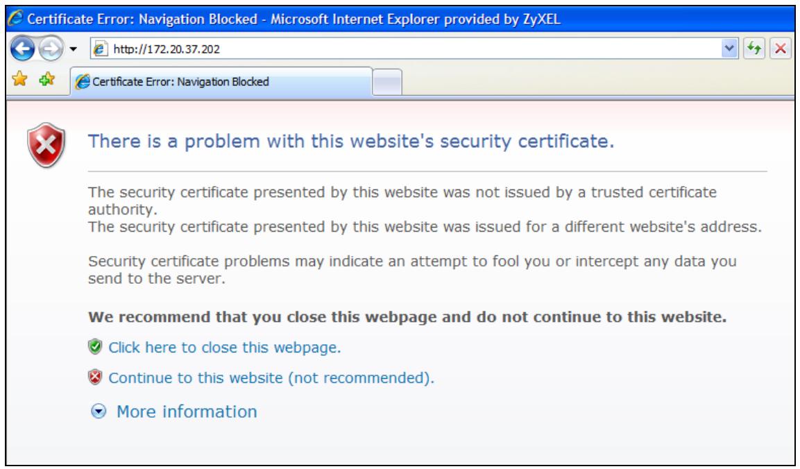
2 Click Continue to this website (not recommended).
3 In the Address Bar, click Certificate Error > View certificates.
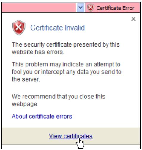
4 In the Certificate dialog box, click Install Certificate.
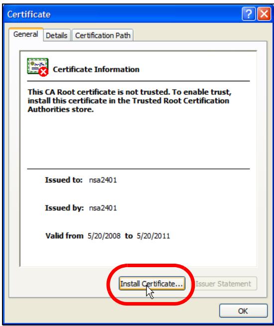
5 In the Certificate Import Wizard, click Next.
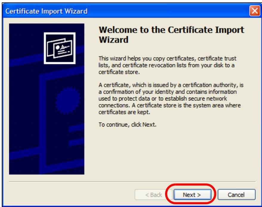
6 If you want Internet Explorer to Automatically select certificate store based on the type of certificate, click Next again and then go to step 9.
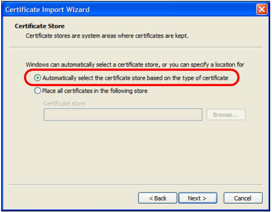
7 Otherwise, select Place all certificates in the following store and then click Browse.
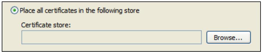
8 In the Select Certificate Store dialog box, choose a location in which to save the certificate and then click OK.
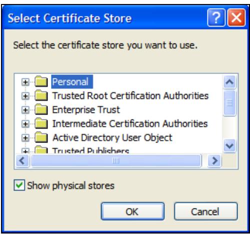
9 In the Completing the Certificate Import Wizard screen, click Finish.
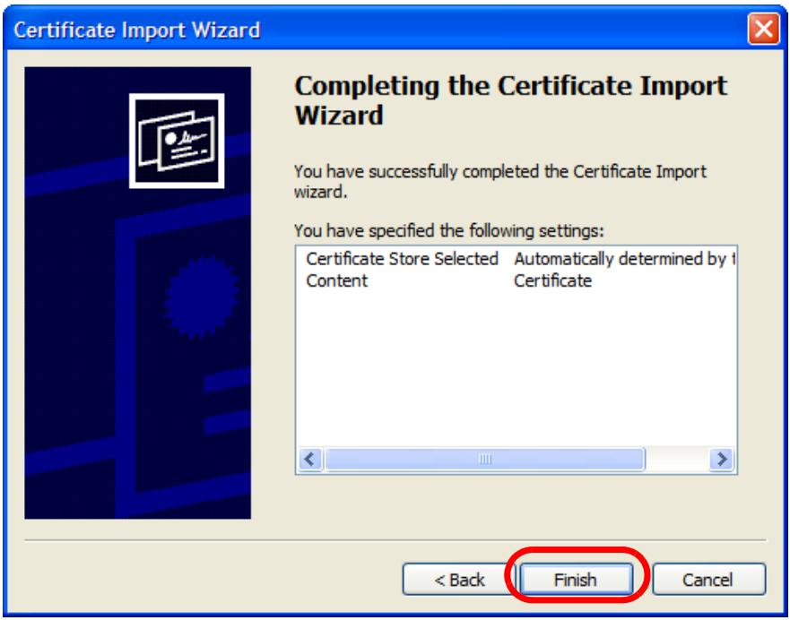
10 If you are presented with another Security Warning, click Yes.
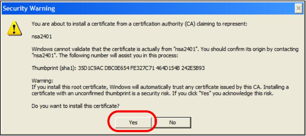
11 Finally, click OK when presented with the successful certificate installation message.
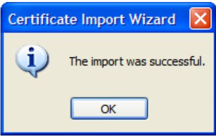
12 The next time you start Internet Explorer and go to a Zyxel Web Configurator page, a sealed padlock icon appears in the address bar. Click it to view the page's Website Identification information.
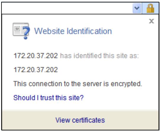
Installing a Stand-Alone Certificate File in Internet Explorer
Rather than browsing to a Zyxel Web Configurator and installing a public key certificate when prompted, you can install a stand-alone certificate file if one has been issued to you.
1 Double-click the public key certificate file.

CA.cer
2 In the security warning dialog box, click Open.
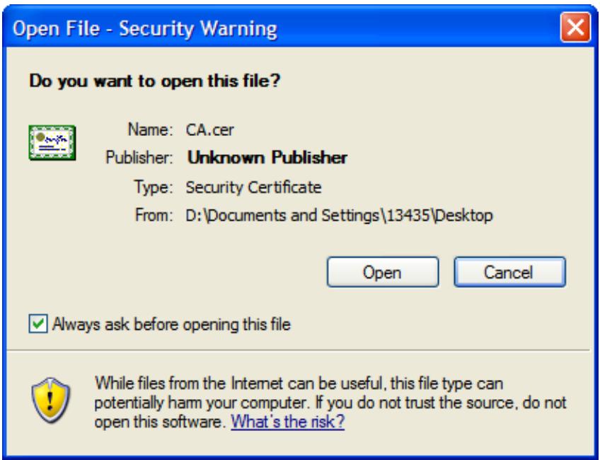
3 Refer to steps 4-12 in the Internet Explorer procedure beginning on page 199 to complete the installation process.
Removing a Certificate in Internet Explorer
This section shows you how to remove a public key certificate in Internet Explorer 7 on Windows XP.
1 Open Internet Explorer and click Tools > Internet Options.
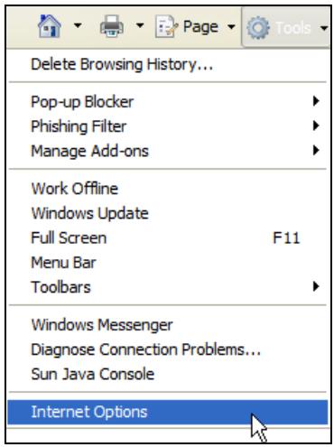
2 In the Internet Options dialog box, click Content > Certificates.
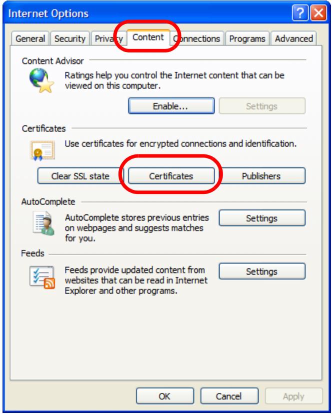
3 In the Certificates dialog box, click the Trusted Root Certificates Authorities tab, select the certificate that you want to delete, and then click Remove.
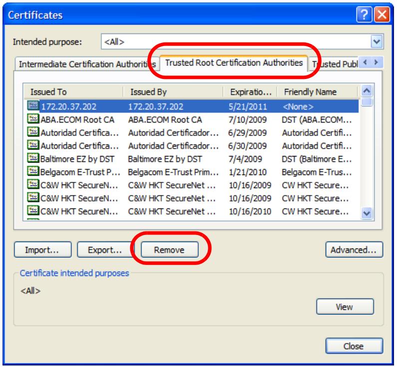
4 In the Certificates confirmation, click Yes.
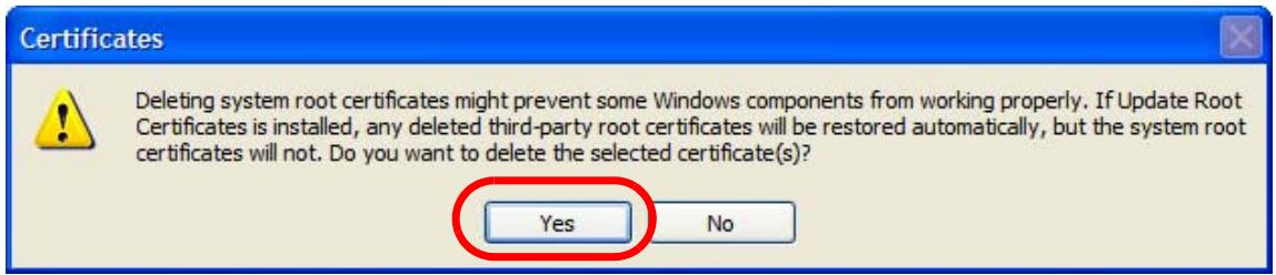
5 In the Root Certificate Store dialog box, click Yes.
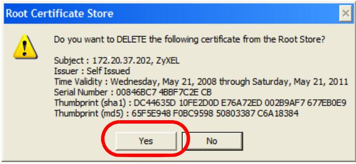
6 The next time you go to the web site that issued the public key certificate you just removed, a certification error appears.
Firefox
The following example uses Mozilla Firefox 2 on Windows XP Professional; however, the screens can also apply to Firefox 2 on all platforms.
1 If your device's Web Configurator is set to use SSL certification, then the first time you browse to it you are presented with a certification error.
2 Select Accept this certificate permanently and click OK.
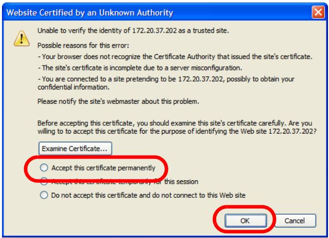
3 The certificate is stored and you can now connect securely to the Web Configurator. A sealed padlock appears in the address bar, which you can click to open the Page Info > Security window to view the web page's security information.
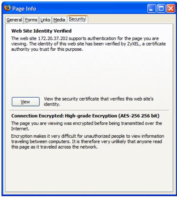
Installing a Stand-Alone Certificate File in Firefox
Rather than browsing to a Zyxel Web Configurator and installing a public key certificate when prompted, you can install a stand-alone certificate file if one has been issued to you.
1 Open Firefox and click Tools > Options.
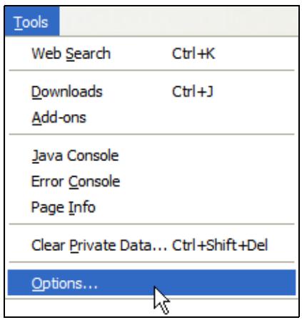
2 In the Options dialog box, click Advanced > Encryption > View Certificates.
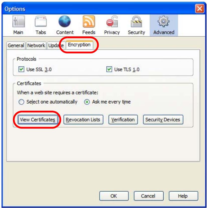
3 In the Certificate Manager dialog box, click Web Sites > Import.
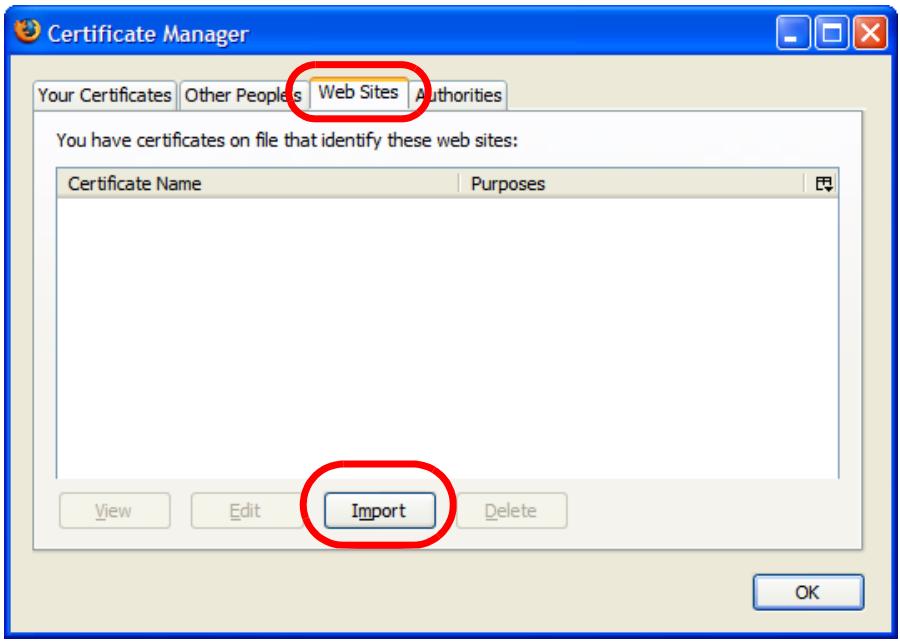
4 Use the Select File dialog box to locate the certificate and then click Open.
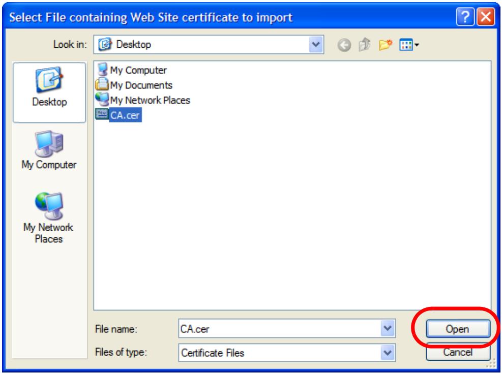
5 The next time you visit the web site, click the padlock in the address bar to open the Page Info > Security window to see the web page's security information.
Removing a Certificate in Firefox
This section shows you how to remove a public key certificate in Firefox 2.
1 Open Firefox and click Tools > Options.
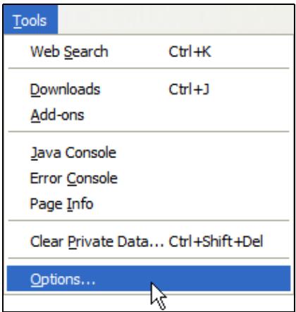
2 In the Options dialog box, click Advanced > Encryption > View Certificates.

3 In the Certificate Manager dialog box, select the Web Sites tab, select the certificate that you want to remove, and then click Delete.
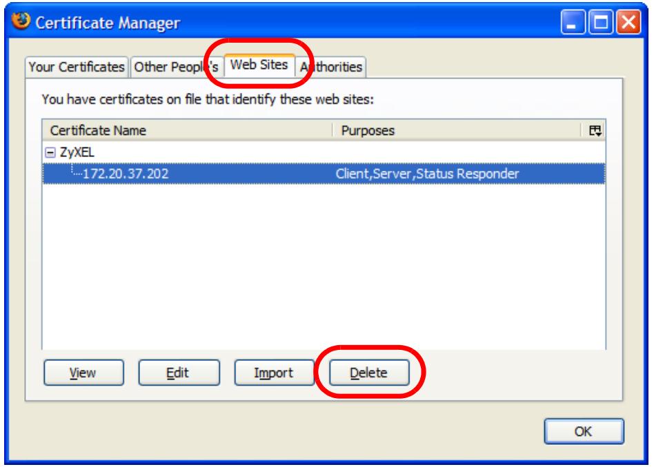
4 In the Delete Web Site Certificates dialog box, click OK.
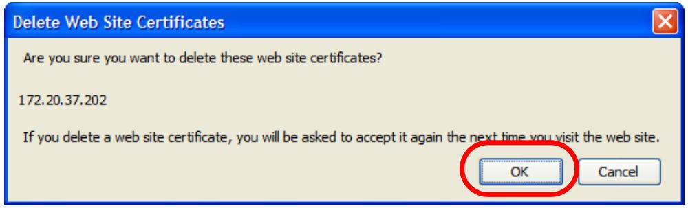
5 The next time you go to the web site that issued the public key certificate you just removed, a certification error appears.
Overview
IPv6 (Internet Protocol version 6), is designed to enhance IP address size and features. The increase in IPv6 address size to 128 bits (from the 32-bit IPv4 address) allows up to 3.4 × 10^38 IP addresses.
IPv6 Addressing
The 128-bit IPv6 address is written as eight 16-bit hexadecimal blocks separated by colons (:). This is an example IPv6 address 2001:0db8:1a2b:0015:0000:0000:1a2f:0000.
IPv6 addresses can be abbreviated in two ways:
- Leading zeros in a block can be omitted. So 2001:0db8:1a2b:0015:0000:0000:1a2f:0000 can be written as 2001:db8:1a2b:15:0:0:1a2f:0.
- Any number of consecutive blocks of zeros can be replaced by a double colon. A double colon can only appear once in an IPv6 address. So 2001:0db8:0000:0000:1a2f:0000:0000:0015 can be written as 2001:0db8::1a2f:0000:0000:0015, 2001:0db8:0000:0000:1a2f::0015, 2001:db8::1a2f:0:0:15 or 2001:db8:0:0:1a2f::15.
Prefix and Prefix Length
Similar to an IPv4 subnet mask, IPv6 uses an address prefix to represent the network address. An IPv6 prefix length specifies how many most significant bits (start from the left) in the address compose the network address. The prefix length is written as "/x" where x is a number. For example,
2001:db8:1a2b:15::1a2f:0/32
means that the first 32 bits (2001:db8) is the subnet prefix.
Link-local Address
A link-local address uniquely identifies a device on the local network (the LAN). It is similar to a “private IP address” in IPv4. You can have the same link-local address on multiple interfaces on a device. A link-local unicast address has a predefined prefix of fe80::/10. The link-local unicast address format is as follows.
Table 86 Link-local Unicast Address Format
| 1111 1110 10 | 0 | Interface ID |
| 10 bits | 54 bits | 64 bits |
Global Address
A global address uniquely identifies a device on the Internet. It is similar to a “public IP address” in IPv4. A global unicast address starts with a 2 or 3.
Unspecified Address
An unspecified address (0:0:0:0:0:0:0 or ::) is used as the source address when a device does not have its own address. It is similar to "0.0.0.0" in IPv4.
Loopback Address
A loopback address (0:0:0:0:0:0:1 or ::1) allows a host to send packets to itself. It is similar to "127.0.0.1" in IPv4.
Multicast Address
In IPv6, multicast addresses provide the same functionality as IPv4 broadcast addresses. Broadcasting is not supported in IPv6. A multicast address allows a host to send packets to all hosts in a multicast group.
Multicast scope allows you to determine the size of the multicast group. A multicast address has a predefined prefix of ff00::/8. The following table describes some of the predefined multicast addresses.
Table 87 Predefined Multicast Address
| MULTICAST ADDRESS | DESCRIPTION |
| FF01:0:0:0:0:0:0:1 | All hosts on a local node. |
| FF01:0:0:0:0:0:0:2 | All routers on a local node. |
| FF02:0:0:0:0:0:0:1 | All hosts on a local connected link. |
| FF02:0:0:0:0:0:0:2 | All routers on a local connected link. |
| FF05:0:0:0:0:0:0:2 | All routers on a local site. |
| FF05:0:0:0:0:0:1:3 | All DHCP severs on a local site. |
The following table describes the multicast addresses which are reserved and can not be assigned to a multicast group.
Table 88 Reserved Multicast Address
Both an IPv6 address and IPv6 subnet mask compose of 128-bit binary digits, which are divided into eight 16-bit blocks and written in hexadecimal notation. Hexadecimal uses four bits for each character (1 \~ 10, A \~ F). Each block's 16 bits are then represented by four hexadecimal characters. For example, FFFF:FFFF:FFFF:FFFF:FC00:0000:0000:0000.
Interface ID
In IPv6, an interface ID is a 64-bit identifier. It identifies a physical interface (for example, an Ethernet port) or a virtual interface (for example, the management IP address for a VLAN). One interface should have a unique interface ID.
EUI-64
The EUI-64 (Extended Unique Identifier) defined by the IEEE (Institute of Electrical and Electronics Engineers) is an interface ID format designed to adapt with IPv6. It is derived from the 48-bit (6-byte) Ethernet MAC address as shown next. EUI-64 inserts the hex digits fffe between the third and fourth bytes of the MAC address and complements the seventh bit of the first byte of the MAC address. See the following example.
Table 89
With stateless autoconfiguration in IPv6, addresses can be uniquely and automatically generated. Unlike DHCPv6 (Dynamic Host Configuration Protocol version six) which is used in IPv6 stateful autoconfiguration, the owner and status of addresses don't need to be maintained by a DHCP server. Every IPv6 device is able to generate its own and unique IP address automatically when IPv6 is initiated on its interface. It combines the prefix and the interface ID (generated from its own Ethernet MAC address, see Interface ID and EUI-64) to form a complete IPv6 address.
When IPv6 is enabled on a device, its interface automatically generates a link-local address (beginning with fe80).
When the interface is connected to a network with a router and the NWA/WAC is set to automatically obtain an IPv6 network prefix from the router for the interface, it generates ^1 another address which combines its interface ID and global and subnet information advertised from the router. This is a routable global IP address.
DHCPv6
The Dynamic Host Configuration Protocol for IPv6 (DHCPv6, RFC 3315) is a server-client protocol that allows a DHCP server to assign and pass IPv6 network addresses, prefixes and other configuration information to DHCP clients. DHCPv6 servers and clients exchange DHCP messages using UDP.
Each DHCP client and server has a unique DHCP Unique IDentifier (DUID), which is used for identification when they are exchanging DHCPv6 messages. The DUID is generated from the MAC address, time, vendor assigned ID and/or the vendor's private enterprise number registered with the IANA. It should not change over time even after you reboot the device.
Identity Association
An Identity Association (IA) is a collection of addresses assigned to a DHCP client, through which the server and client can manage a set of related IP addresses. Each IA must be associated with exactly one interface. The DHCP client uses the IA assigned to an interface to obtain configuration from a DHCP server for that interface. Each IA consists of a unique IAID and associated IP information.
The IA type is the type of address in the IA. Each IA holds one type of address. IA_NA means an identity association for non-temporary addresses and IA_TA is an identity association for temporary addresses. An IA_NA option contains the T1 and T2 fields, but an IA_TA option does not. The DHCPv6 server uses T1 and T2 to control the time at which the client contacts with the server to extend the lifetimes on any addresses in the IA_NA before the lifetimes expire. After T1, the client sends the server (S1) (from which the addresses in the IA_NA were obtained) a Renew message. If the time T2 is reached and the server does not respond, the client sends a Rebind message to any available server (S2). For an IA_TA, the client may send a Renew or Rebind message at the client's discretion.
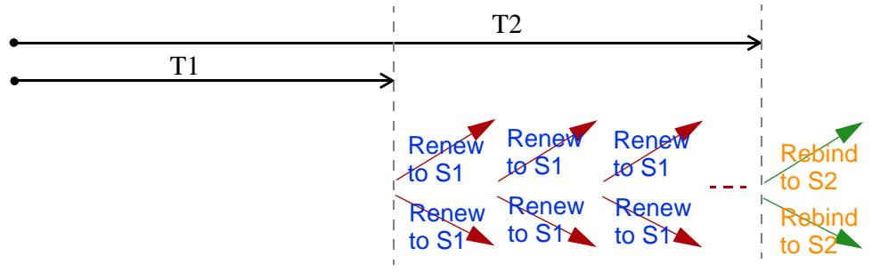
flowchart
graph LR
    A["T1"] --> B["T2"]
    B --> C["..."]
    C --> D["Rebind to S2"]
    B --> E["Rebind to S2"]
    B --> F["Renew to S1"]
    B --> G["Renew to S1"]
    B --> H["Renew to S1"]
    style A fill:#fff,stroke:#000
    style B fill:#fff,stroke:#000
    style C fill:#fff,stroke:#000
    style D fill:#fff,stroke:#000
    style E fill:#fff,stroke:#000
    style F fill:#fff,stroke:#000
    style G fill:#fff,stroke:#000
    style H fill:#fff,stroke:#000
DHCP Relay Agent
A DHCP relay agent is on the same network as the DHCP clients and helps forward messages between the DHCP server and clients. When a client cannot use its link-local address and a well-known multicast address to locate a DHCP server on its network, it then needs a DHCP relay agent to send a message to a DHCP server that is not attached to the same network.
The DHCP relay agent can add the remote identification (remote-ID) option and the interface-ID option to the Relay-Forward DHCPv6 messages. The remote-ID option carries a user-defined string, such as the system name. The interface-ID option provides slot number, port information and the VLAN ID to the DHCPv6 server. The remote-ID option (if any) is stripped from the Relay-Reply messages before the relay agent sends the packets to the clients. The DHCP server copies the interface-ID option from the Relay-Forward message into the Relay-Reply message and sends it to the relay agent. The interface-ID should not change even after the relay agent restarts.
Prefix Delegation
Prefix delegation enables an IPv6 router to use the IPv6 prefix (network address) received from the ISP (or a connected uplink router) for its LAN. The NWA/WAC uses the received IPv6 prefix (for example, 2001:db2::/48) to generate its LAN IP address. Through sending Router Advertisements (RAs) regularly by multicast, the NWA/WAC passes the IPv6 prefix information to its LAN hosts. The hosts then can use the prefix to generate their IPv6 addresses.
ICMPv6
Internet Control Message Protocol for IPv6 (ICMPv6 or ICMP for IPv6) is defined in RFC 4443. ICMPv6 has a preceding Next Header value of 58, which is different from the value used to identify ICMP for IPv4. ICMPv6 is an integral part of IPv6. IPv6 nodes use ICMPv6 to report errors encountered in packet processing and perform other diagnostic functions, such as "ping".
Neighbor Discovery Protocol (NDP)
The Neighbor Discovery Protocol (NDP) is a protocol used to discover other IPv6 devices and track neighbor's reachability in a network. An IPv6 device uses the following ICMPv6 messages types:
- Neighbor solicitation: A request from a host to determine a neighbor's link-layer address (MAC address) and detect if the neighbor is still reachable. A neighbor being “reachable” means it responds to a neighbor solicitation message (from the host) with a neighbor advertisement message.
- Neighbor advertisement: A response from a node to announce its link-layer address.
- Router solicitation: A request from a host to locate a router that can act as the default router and forward packets.
- Router advertisement: A response to a router solicitation or a periodical multicast advertisement from a router to advertise its presence and other parameters.
IPv6 Cache
An IPv6 host is required to have a neighbor cache, destination cache, prefix list and default router list. The NWA/WAC maintains and updates its IPv6 caches constantly using the information from response messages. In IPv6, the NWA/WAC configures a link-local address automatically, and then sends a neighbor solicitation message to check if the address is unique. If there is an address to be resolved or verified, the NWA/WAC also sends out a neighbor solicitation message. When the NWA/WAC receives a neighbor advertisement in response, it stores the neighbor's link-layer address in the neighbor cache. When the NWA/WAC uses a router solicitation message to query for a router and receives a router advertisement message, it adds the router's information to the neighbor cache, prefix list and destination cache. The NWA/WAC creates an entry in the default router list cache if the router can be used as a default router.
When the NWA/WAC needs to send a packet, it first consults the destination cache to determine the next hop. If there is no matching entry in the destination cache, the NWA/WAC uses the prefix list to determine whether the destination address is on-link and can be reached directly without passing through a router. If the address is onlink, the address is considered as the next hop. Otherwise, the NWA/WAC determines the next-hop from the default router list or routing table. Once the next hop IP address is known, the NWA/WAC looks into the neighbor cache to get the link-layer address and sends the packet when the neighbor is reachable. If the NWA/WAC cannot find an entry in the neighbor cache or the state for the neighbor is not reachable, it starts the address resolution process. This helps reduce the number of IPv6 solicitation and advertisement messages.
Multicast Listener Discovery
The Multicast Listener Discovery (MLD) protocol (defined in RFC 2710) is derived from IPv4's Internet Group Management Protocol version 2 (IGMPv2). MLD uses ICMPv6 message types, rather than IGMP message types. MLDv1 is equivalent to IGMPv2 and MLDv2 is equivalent to IGMPv3.
MLD allows an IPv6 switch or router to discover the presence of MLD listeners who wish to receive multicast packets and the IP addresses of multicast groups the hosts want to join on its network.
MLD snooping and MLD proxy are analogous to IGMP snooping and IGMP proxy in IPv4.
MLD filtering controls which multicast groups a port can join.
MLD Messages
A multicast router or switch periodically sends general queries to MLD hosts to update the multicast forwarding table. When an MLD host wants to join a multicast group, it sends an MLD Report message for that address.
An MLD Done message is equivalent to an IGMP Leave message. When an MLD host wants to leave a multicast group, it can send a Done message to the router or switch. The router or switch then sends a group-specific query to the port on which the Done message is received to determine if other devices connected to this port should remain in the group.
Example - Enabling IPv6 on Windows XP/2003/Vista
By default, Windows XP and Windows 2003 support IPv6. This example shows you how to use the ipv6 install command on Windows XP/2003 to enable IPv6. This also displays how to use the ipconfig command to see auto-generated IP addresses.
C:\>ipv6 install
Installing...
Succeeded.

C:\>ipconfig

Windows IP Configuration

Ethernet adapter Local Area Connection:

Connection-specific DNS Suffix . :
IP Address. . . . . . . . . . . . : 10.1.1.46
Subnet Mask . . . . . . . . . . . . : 255.255.255.0
IP Address. . . . . . . . . . . . . : fe80::2d0:59ff:feb8:103c%4
Default Gateway . . . . . . . . . : 10.1.1.254
IPv6 is installed and enabled by default in Windows Vista. Use the ipconfig command to check your automatic configured IPv6 address as well. You should see at least one IPv6 address available for the interface on your computer.
Example - Enabling DHCPv6 on Windows XP
Windows XP does not support DHCPv6. If your network uses DHCPv6 for IP address assignment, you have to additionally install a DHCPv6 client software on your Windows XP. (Note: If you use static IP addresses or Router Advertisement for IPv6 address assignment in your network, ignore this section.)
This example uses Dibbler as the DHCPv6 client. To enable DHCPv6 client on your computer:
1 Install Dibbler and select the DHCPv6 client option on your computer.
2 After the installation is complete, select Start > All Programs > Dibbler-DHCPv6 > Client Install as service.
3 Select Start > Control Panel > Administrative Tools > Services.
4 Double click Dibbler - a DHCPv6 client.
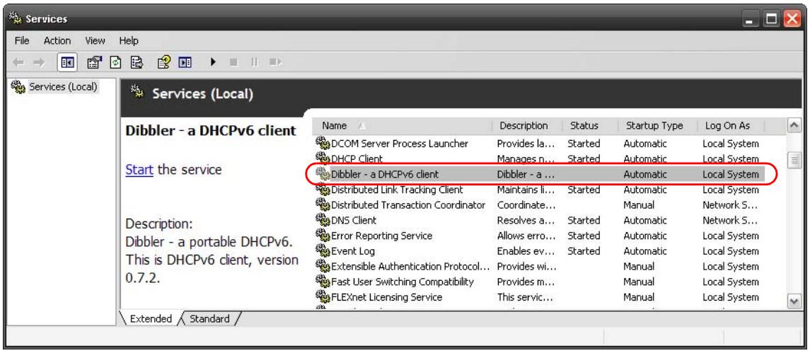
5 Click Start and then OK.
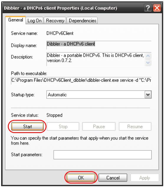
6 Now your computer can obtain an IPv6 address from a DHCPv6 server.
Example - Enabling IPv6 on Windows 7
Windows 7 supports IPv6 by default. DHCPv6 is also enabled when you enable IPv6 on a Windows 7 computer.
To enable IPv6 in Windows 7:
1 Select Control Panel > Network and Sharing Center > Local Area Connection.
2 Select the Internet Protocol Version 6 (TCP/IPv6) checkbox to enable it.
3 Click OK to save the change.
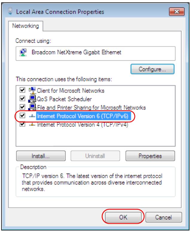
4 Click Close to exit the Local Area Connection Status screen.
5 Select Start > All Programs > Accessories > Command Prompt.
6 Use the ipconfig command to check your dynamic IPv6 address. This example shows a global address (2001:b021:2d::1000) obtained from a DHCP server.
C:\>ipconfig
Windows IP Configuration
Ethernet adapter Local Area Connection:
Connection-specific DNS Suffix . :
IPv6 Address. . . . . . . . . . . : 2001:b021:2d::1000
Link-local IPv6 Address . . . . . : fe80::25d8:dcab:c80a:5189%11
IPv4 Address. . . . . . . . . . . : 172.16.100.61
Subnet Mask . . . . . . . . . . . : 255.255.255.0
Default Gateway . . . . . . . . . : fe80::213:49ff:feaa:7125%11
172.16.100.254
APPENDIX C
Customer Support
In the event of problems that cannot be solved by using this manual, you should contact your vendor. If you cannot contact your vendor, then contact a Zyxel office for the region in which you bought the device.
See http://www.zyxel.com/homepage.shtml and also
http://www.zyxel.com/about_zyxel/zyxel_worldwide.shtml for the latest information.
Please have the following information ready when you contact an office.
Required Information
- Product model and serial number.
- Warranty Information.
- Date that you received your device.
- Brief description of the problem and the steps you took to solve it.
Corporate Headquarters (Worldwide)
Taiwan
• Zyxel Communications Corporation
- http://www.zyxel.com
Asia
China
• Zyxel Communications (Shanghai) Corp.
Zyxel Communications (Beijing) Corp.
Zyxel Communications (Tianjin) Corp.
- http://www.zyxel.cn
India
• Zyxel Technology India Pvt Ltd
- http://www.zyxel.in
Kazakhstan
- Zyxel Kazakhstan
- http://www.zyxel.kz
Korea
- Zyxel Korea Corp.
- http://www.zyxel.kr
Malaysia
• Zyxel Malaysia Sdn Bhd.
- http://www.zyxel.com.my
Pakistan
• Zyxel Pakistan (Pvt.) Ltd.
- http://www.zyxel.com.pk
Philippines
- Zyxel Philippines
- http://www.zyxel.com.ph
Singapore
• Zyxel Singapore Pte Ltd.
- http://www.zyxel.com.sg
Taiwan
• Zyxel Communications Corporation
- http://www.zyxel.com/tw/zh/
Thailand
• Zyxel Thailand Co., Ltd
- http://www.zyxel.co.th
Vietnam
• Zyxel Communications Corporation-Vietnam Office
- http://www.zyxel.com/vn/vi
Europe
Austria
- Zyxel Lithuania
- http://www.zyxel.com/lt/lt/homepage.shtml
Netherlands
- Zyxel Benelux
- http://www.zyxel.nl
Norway
• Zyxel Communications
- http://www.zyxel.no
Poland
• Zyxel Communications Poland
- http://www.zyxel.pl
Romania
- Zyxel Romania
- http://www.zyxel.com/ro/ro
Russia
- Zyxel Russia
- http://www.zyxel.ru
Slovakia
• Zyxel Communications Czech s.r.o. organizacna zlozka
- http://www.zyxel.sk
Spain
• Zyxel Communications ES Ltd
- http://www.zyxel.es
Sweden
• Zyxel Communications
- http://www.zyxel.se
Switzerland
- Studerus AG
- http://www.zyxel.ch/
Turkey
- Zyxel Turkey A.S.
- http://www.zyxel.com.tr
UK
• Zyxel Communications UK Ltd.
- http://www.zyxel.co.uk
Ukraine
- Zyxel Ukraine
- http://www.ua.zyxel.com
Latin America
Argentina
• Zyxel Communication Corporation
- http://www.zyxel.com/ec/es/
Brazil
• Zyxel Communications Brasil Ltda.
- https://www.zyxel.com/br/pt/
Ecuador
• Zyxel Communication Corporation
- http://www.zyxel.com/ec/es/
Middle East
Israel
• Zyxel Communication Corporation
- http://il.zyxel.com/homepage.shtml
Middle East
• Zyxel Communication Corporation
- http://www.zyxel.com/me/en/
North America
USA
• Zyxel Communications, Inc. - North America Headquarters
- http://www.zyxel.com/us/en/
Oceania
Australia
• Zyxel Communications Corporation
- http://www.zyxel.com/au/en/
Africa
South Africa
- Nology (Pty) Ltd.
- http://www.zyxel.co.za
APPENDIX D
Legal Information
Copyright
Copyright © 2017 by Zyxel Communications Corporation.
The contents of this publication may not be reproduced in any part or as a whole, transcribed, stored in a retrieval system, translated into any language, or transmitted in any form or by any means, electronic, mechanical, magnetic, optical, chemical, photocopying, manual, or otherwise, without the prior written permission of Zyxel Communications Corporation.
Published by Zyxel Communications Corporation. All rights reserved.
Disclaimers
Zyxel does not assume any liability arising out of the application or use of any products, or software described herein. Neither does it convey any license under its patent rights nor the patent rights of others. Zyxel further reserves the right to make changes in any products described herein without notice. This publication is subject to change without notice.
Your use of the NWA/WAC is subject to the terms and conditions of any related service providers.
Trademarks
Trademarks mentioned in this publication are used for identification purposes only and may be properties of their respective owners.
Regulatory Notice and Statement
UNITED STATES of AMERICA

The following information applies if you use the product within USA area.
FCC EMC Statement
- This device complies with part 15 of the FCC Rules. Operation is subject to the following two conditions: (1) This device may not cause harmful interference, and
(2) this device must accept any interference received, including interference that may cause undesired operation. - Changes or modifications not expressly approved by the party responsible for compliance could void the user's authority to operate the device.
- This product has been tested and complies with the specifications for a Class B digital device, pursuant to Part 15 of the FCC Rules. These limits are designed to provide reasonable protection against harmful interference in a residential installation. This device generates, uses, and can radiate radio frequency energy and, if not installed and used according to the instructions, may cause harmful interference to radio communications. However, there is no guarantee that interference will not occur in a particular installation.
- If this device does cause harmful interference to radio or television reception, which is found by turning the device off and on, the user is encouraged to try to correct the interference by one or more of the following measures:
• Reorient or relocate the receiving antenna - Increase the separation between the devices
- Connect the equipment to an outlet other than the receiver's
- Consult a dealer or an experienced radio/TV technician for assistance
FCC Caution: Any changes or modifications not expressly approved by the party responsible for compliance could void the user's authority to operate this equipment.
FCC Radiation Exposure Statement
• This device complies with FCC RF radiation exposure limits set forth for an uncontrolled environment.
- This transmitter must be at least 20 cm from the user and must not be co-located or operating in conjunction with any other antenna or transmitter. This transmitter must be at least 22 cm(NWA5123-NI) from the user and must not be co-located or operating in conjunction with any other antenna or transmitter. This transmitter must be at least 30 cm(WAC6553D-E) from the user and must not be co-located or operating in conjunction with any other antenna or transmitter.
• Country Code selection feature to be disabled for products marketed to the US/CANADA
• Operation of this device is restricted to indoor use only. (WAC6553D-E is a device for outdoor use.)
CANADA
The following information applies if you use the product within Canada area.
Industry Canada ICES statement
CAN ICES-3 (B)/NMB-3(B)
Industry Canada RSS-GEN & RSS-247 statement
- This device complies with Industry Canada license-exempt RSS standard(s). Operation is subject to the following two conditions: (1) this device may not cause interference, and (2) this device must accept any interference, including interference that may cause undesired operation of the device.
- This radio transmitter (2468C-NWA5123AC (NWA5123-AC, NWA1123-AC v2), 2468C-WAC6502D-E (WAC6502D-S, WAC6502D-E), 2468C-WAC6503D-S (WAC6503D-S), 2468C-WAC6553D-E (WAC6553D-E), 2468C-WAC6103DI (WAC6103DI), 2468C-WAC5302DS (WAC5302D-S)) has been approved by Industry Canada to operate with the antenna types listed below with the maximum permissible gain and required antenna impedance for each antenna type indicated. Antenna types not included in this list, having a gain greater than the maximum gain indicated for that type, are strictly prohibited for use with this device.
Antenna Information
| ANTENNA MODEL | NO. | TYPE | CONNECTOR | 2.4 G GAIN | 5G GAIN | REMARK |
| NWA5123-AC 2.4 GHz Antenna | 1 | PIFA | U.FL | 3.08 (2400-2483.5MHz) | ||
| 2 | PIFA | U.FL | 3.07 (2400-2483.5MHz) | |||
| NWA5123-AC 5 GHz Antenna | 3 | PIFA | U.FL | 4.06 (5150-5250 MHz)3.91 (5725-5850 MHz) | ||
| 4 | PIFA | U.FL | 3.99 (5150-5250 MHz)3.79 (5725-5850 MHz) | |||
| WAC6502D-E | Dipole | RSMA | 5 | 7 | ||
| WAC6502D-S | Dipole | IPEX | 4 | 6 | ||
| WAC6503D-S | Dipole | IPEX | 4 | 6 | ||
| ZXL04-22008A | Dipole | N type | 4.5 | 7 | ||
| SINBON / 2.4 G & 5 G Metal & PCB Antenna | 1 | PIFA | U.FL | 3.28 | Ceiling Mounted: Antenna 1, 2, 3Wall Mounted: Antenna 1, 2, 4 | |
| 2 | PIFA | U.FL | 3.37 | |||
| 3 | PIFA | U.FL | 3.15 | |||
| 4 | Dipole | U.FL | 4.33 | |||
| 5 | Loop | U.FL | 4.38 (5150-5250 MHz)4.23 (5725-5850 MHz) | Ceiling Mounted: Antenna 5, 6, 7Wall Mounted: Antenna 5, 6, 8 | ||
| 6 | Loop | U.FL | 4.31 (5150-5250 MHz)4.22 (5725-5850 MHz) | |||
| 7 | Loop | U.FL | 4.38 (5150-5250 MHz)4.36 (5725-5850 MHz) | |||
| 8 | Dipole | U.FL | 5.12 (5150-5250 MHz)5.20 (5725-5850 MHz) | |||
| 81XCAL15.G01 | Loop | I-PEX | 5.82 (2400-2483.5MHz) | |||
| 81XCAL15.G02 | Loop | I-PEX | 5.02 (2400-2483.5MHz) | |||
| AD751 | PIFA | I-PEX | 5 (5150-5250 MHz)5 (5250-5350 MHz)5 (5470-5725 MHz)5 (5725-5850 MHz) | |||
| A9701685 | PCB | U.FL | 4.0 | |||
| A9701686 | PCB | U.FL | 5.8 | |||
| A9701670 | PCB | U.FL | 5.2 | |||
| A9701671 | PCB | U.FL | 6.1 |
If the product with 5G wireless function operating in 5150-5250 MHz and 5725-5850 MHz, the following attention must be paid,
- The device for operation in the band 5150-5250 MHz is only for indoor use to reduce the potential for harmful interference to co-channel mobile satellite systems.
- For devices with detachable antenna(s), the maximum antenna gain permitted for devices in the band 5725-5850 MHz shall be such that the equipment still complies with the e.i.r.p. limits specified for point-to-point and non-point-to-point operation as appropriate; and
- The worst-case tilt angle(s) necessary to remain compliant with the e.i.r.p. elevation mask requirement set forth in Section 6.2.2(3) of RSS 247 shall be clearly indicated.
If the product with 5G wireless function operating in 5250-5350 MHz and 5470-5725 MHz, the following attention must be paid.
Industry Canada radiation exposure statement
This equipment complies with IC radiation exposure limits set forth for an uncontrolled environment. This equipment should be installed and operated with a minimum distance of 20cm between the radiator and your body.
This equipment complies with IC radiation exposure limits set forth for an uncontrolled environment. This equipment should be installed and operated with a minimum distance of 22cm (NWA5123-NI) between the radiator and your body.
This equipment complies with IC radiation exposure limits set forth for an uncontrolled environment. This equipment should be installed and operated with a minimum distance of 30 cm (WAC6553D-E) between the radiator and your body.
(i) the device for operation in the band 5150-5250 MHz is only for indoor use to reduce the potential for harmful interference to co-channel mobile satellite systems;
(ii) the maximum antenna gain permitted for devices in the bands 5250-5350 MHz and 5470-5725 MHz shall comply with the e.i.r.p. limit; and
(iii) the maximum antenna gain permitted for devices in the band 5725-5825 MHz shall comply with the e.i.r.p. limits specified for point-to-point and non point-to-point operation as appropriate.
(iv) Users should also be advised that high-power radars are allocated as primary users (i.e. priority users) of the bands 5250-5350 MHz and 5650-5850 MHz and that these radars could cause interference and/or damage to LE-LAN devices.
(v) WAC6553D-E is an outdoor device and only uses 5G Band 4 (5725-5850 MHz).
Avertissement:
The following information applies if you use the product within the European Union.
Declaration of Conformity with Regard to EU Directive 1999/5/EC (R&TTE Directive)
Compliance information for 2.4GHz and/or 5GHz wireless products relevant to the EU and other Countries following the EU Directive 1999/5/EC (R&TTE). This device is restricted to indoor use only when operating in the 5150 to 5350 MHz frequency range
- This device is restricted to indoor use only when operating in the 5150 to 5350 MHz frequency range.
| Български (Bulgarian) | С настоящото Zyxel декларира, че това оборудване е в съответствие със съществените изисквания и другите приложими разпоредбите на Директива 1999/5/EC. |
| Español (Spanish) | Por medio de la presente Zyxel declara que el equipo cumple con los requisitos esenciales y cualesquiera otras disposiciones aplicables o exigibles de la Directiva 1999/5/CE. |
| Čeština (Czech) | Zyxel tímto prohlašuje, že tento zařízení je ve shodě se základními požadavky a dalšími příslušnými ustanoveními směrnice 1999/5/EC. |
| Dansk (Danish) | Undertegnede Zyxel erklærer herved, at følgende udstyr udstyr overholder de væsentlige krav og øvrige relevante krav i direktiv 1999/5/EF. |
| Deutsch (German) | Hiermit erklärt Zyxel, dass sich das Gerät Ausstattung in Übereinstimmung mit den grundlegenden Anforderungen und den übrigen einschlägigen Bestimmungen der Richtlinie 1999/5/EU befindet. |
| Eesti keel (Estonian) | Käesolevaga kinnitab Zyxel seadme seadmed vastavust direktiivi 1999/5/EÜ põhinõuetele ja nimetatud direktiivist tulenevatele teistele asjakohastele sätetele. |
| Еллэнνικά (Greek) | ME THN ΠΑΡΟΥΣΑ Zyxel ΔΗΛΩΝΕΙ ΟΤΙ εξοπλισμός ΣΥΜΜΟΡΦΩΝΕΤΑΙ ΠΡΟΣ ΤΙΣ ΟΥΣΙΩΔΕΙΣ ΑΠΑΙΤΗΣΕΙΣ ΚΑΙ ΤΙΣ ΛΟΙΠΕΣ ΣΧΕΤΙΚΕΣ ΔΙΑΤΑΞΕΙΣ ΤΗΣ ΟΔΗΓΙΑΣ 1999/5/EC. |
| English | Hereby, Zyxel declares that this equipment is in compliance with the essential requirements and other relevant provisions of Directive 1999/5/EC. |
| Français (French) | Par la présente Zyxel déclare que l'appareil équipements est conforme aux exigences essentielles et aux autres dispositions pertinentes de la directive 1999/5/EC. |
| Hrvatski (Croatian) | Zyxel ovime izjavljuje da je radijska oprema tipa u skladu s Direktivom 1999/5/EC. |
| Íslenska (Icelandic) | Hér með lýsír, Zyxel því yfir að pessi búnaður er í samræmi við grunnkröfur og önnur viðeigandi ákvæði tilskipunar 1999/5/EC. |
| Italiano (Italian) | Con la presente Zyxel dichiara che questo attrezzatura è conforme ai requisiti essenziali ed alle altre disposizioni pertinenti stabilite dalla direttiva 1999/5/CE. |
| Latviešu valoda (Latvian) | Ar šo Zyxel deklarē, ka iekārtas atbilst Direktīvas 1999/5/EK būtiskajām prasībām un citiem ar to saisītajiem noteikumiem. |
| Lietuvių kalba (Lithuanian) | Šiuo Zyxel deklaruoja, kad šis įranga atitinka esminius reikalavimus ir kitas 1999/5/EB Direktyvos nuostatas. |
| Magyar (Hungarian) | Alulírott, Zyxel nyilatkozom, hogy a berendezés megfelel a vonatkozó alapvetō követelményeknek és az 1999/5/EK irányelv egyéb előirásainak. |
| Malti (Maltese) | Hawnhekk, Zyxel, jiddikjara li dan taghmir jikkonforma mal-ħtiġijiet essenzjali u ma provvedimenti oħrajn relevanti li hemm fid-Dirrettiva 1999/5/EC. |
| Nederlands (Dutch) | Hierbij verklaart Zyxel dat het toestel uitrusting in overeenstemming is met de essentiële eisen en de andere relevante bepalingen van richtlijn 1999/5/EC. |
| Polski (Polish) | Niniejszym Zyxel oświadcza, że sprzęt jest zgodny z zasadniczymi wymogami oraz pozostałymi stosownymi postanowieniami Dyrektywy 1999/5/EC. |
| Português (Portuguese) | Zyxel declara que este equipamento está conforme com os requisitos essenciais e outras disposições da Directiva 1999/5/EC. |
| Română (Romanian) | Prin prezenta, Zyxel declară că acest echipament este în conformitate cu cerințele esențiale și alte prevederi relevante ale Directivei 1999/5/EC. |
| Slovenčina (Slovak) | Zyxel týmto vyhlasuje, že zariadenia spíňa základné požiadavky a všetky príslušné ustanovenia Smernice 1999/5/EC. |
| Slovenščina (Slovene) | Zyxel izjavlja, da je ta oprema v skladu z bistvenimi zahtevami in ostalimi relevantnimi določili direktive 1999/5/EC. |
| Suomi (Finnish) | Zyxel vakuuttaa täten että laitteet tyyppinen laite on direktiivin 1999/5/EY oleellisten vaatimusten ja sită koskevien direktiivin muiden ehtojen mukainen. |
| Svenska (Swedish) | Härmed intygar Zyxel att denna utrustning står I överensstämmelse med de väsentliga egenskapskrav och övriga relevanta bestämmelser som framgår av direktiv 1999/5/EC. |
| Norsk (Norwegian) | Erklærer herved Zyxel at dette utstyret er I samsvar med de grunnleggende kravene og andre relevante bestemmelser I direktiv 1999/5/EF. |
National Restrictions
This product may be used in all EU countries (and other countries following the EU Directive 1999/5/EC) without any limitation except for the countries mentioned below:
In the majority of the EU and other European countries, the 2.4GHz and 5GHz bands have been made available for the use of wireless local area networks (LANs). Later in this document you will find an overview of countries in which additional restrictions or requirements or both are applicable.
The requirements for any country may evolve. Zyxel recommends that you check with the local authorities for the latest status of their national regulations for both the 2.4GHz and 5GHz wireless LANs.
The following countries have restrictions and/or requirements in addition to those given in the table labeled “Overview of Regulatory Requirements for Wireless LANs”:
Belgium
The Belgian Institute for Postal Services and Telecommunications (BIPT) must be notified of any outdoor wireless link having a range exceeding 300 meters. Please check http://www.bipt.be for more details.
In Denmark, the band 5150 - 5350 MHz is also allowed for outdoor usage.
This product meets the National Radio Interface and the requirements specified in the National Frequency Allocation Table for Italy. Unless this wireless LAN product is operating within the boundaries of the owner's property, its use requires a “general authorization.” Please check http://www.sviluppoeconomico.gov.it/ for more details.
The outdoor usage of the 2.4 GHz band requires an authorization from the Electronic Communications Office. Please check http://www.esd.lv for more details.
2.4 GHz frekvenèu joslas izmantoðanai árpus telpâm nepiecieðama atiauja no Elektronisko sakaru direkcijas. Vairâk informâcijas: http://www.esd.lv.
Notes:
-
Although Norway, Switzerland and Liechtenstein are not EU member states, the EU Directive 1999/5/EC has also been implemented in those countries.
-
The regulatory limits for maximum output power are specified in EIRP. The EIRP level (in dBm) of a device can be calculated by adding the gain of the antenna used(specified in dBi) to the output power available at the connector (specified in dBm).
List of national codes
| COUNTRY | ISO 3166 2 LETTER CODE | COUNTRY | ISO 3166 2 LETTER CODE |
| Austria | AT | Liechtenstein | LI |
| Belgium | BE | Lithuania | LT |
| Bulgaria | BG | Luxembourg | LU |
| Croatia | HR | Malta | MT |
| Cyprus | CY | Netherlands | NL |
| Czech Republic | CR | Norway | NO |
| Denmark | DK | Poland | PL |
| Estonia | EE | Portugal | PT |
| Finland | FI | Romania | RO |
| France | FR | Serbia | RS |
| Germany | DE | Slovakia | SK |
| Greece | GR | Slovenia | SI |
| Hungary | HU | Spain | ES |
| Iceland | IS | Sweden | SE |
| Ireland | IE | Switzerland | CH |
| Italy | IT | Turkey | TR |
| Latvia | LV | United Kingdom | GB |
Professional installation instruction (WAC6553D-E)
Please be advised that due to the unique function supplied by this product, the device is intended for use with our interactive entertainment software and licensed third-party only. The product will be distributed through controlled distribution channel and installed by trained professional and will not be sold directly to the general public through retail store.
1 Installation personal
This product is designed for specific application and needs to be installed by a qualified personal who has RF and related rule knowledge. The general user shall not attempt to install or change the setting.
2 Installation location
The product shall be installed at a location where the radiating antenna can be kept 30 cm from nearby person in normal operation condition to meet regulatory RF exposure requirement.
3 External antenna
Use only the antennas which have been approved by Zyxel Communications Corporation. The non-approved antenna(s) may produce unwanted spurious or excessive RF transmitting power which may lead to the violation of FCC/IC limit and is prohibited.
4 Installation procedure
Please refer to user's manual for the detail.
5 Warning
Please carefully select the installation position and make sure that the final output power does not exceed the limit set force in relevant rules. The violation of the rule could lead to serious federal penalty.
- Do not use this product near water, for example, in a wet basement or near a swimming pool.
- Do not expose your device to dampness, dust or corrosive liquids.
- Do not store things on the device.
- Do not obstruct the device ventilation slots as insufficient airflow may harm your device. For example, do not place the device in an enclosed space such as a box or on a very soft surface such as a bed or sofa.
- Do not install, use, or service this device during a thunderstorm. There is a remote risk of electric shock from lightning.
- Connect ONLY suitable accessories to the device.
- Do not open the device or unit. Opening or removing covers can expose you to dangerous high voltage points or other risks. ONLY qualified service personnel should service or disassemble this device. Please contact your vendor for further information.
• Make sure to connect the cables to the correct ports.
- Place connecting cables carefully so that no one will step on them or stumble over them.
• Always disconnect all cables from this device before servicing or disassembling.
- Do not remove the plug and connect it to a power outlet by itself; always attach the plug to the power adaptor first before connecting it to a power outlet.
- Do not allow anything to rest on the power adaptor or cord and do NOT place the product where anyone can walk on the power adaptor or cord.
- Please use the provided or designated connection cables/power cables/adaptors. Connect it to the right supply voltage (for example, 110V AC in North America or 230V AC in Europe). If the power adaptor or cord is damaged, it might cause electrocution. Remove it from the device and the power source, repairing the power adapter or cord is prohibited. Contact your local vendor to order a new one.
- Do not use the device outside, and make sure all the connections are indoors. There is a remote risk of electric shock from lightning.
- CAUTION: Risk of explosion if battery is replaced by an incorrect type, dispose of used batteries according to the instruction. Dispose them at the applicable collection point for the recycling of electrical and electronic devices. For detailed information about recycling of this product, please contact your local city office, your household waste disposal service or the store where you purchased the product.
- The following warning statements apply, where the disconnect device is not incorporated in the device or where the plug on the power supply cord is intended to serve as the disconnect device,
- For permanently connected devices, a readily accessible disconnect device shall be incorporated external to the device;
- For pluggable devices, the socket-outlet shall be installed near the device and shall be easily accessible.
Environment statement
ErP (Energy-related Products)
Zyxel products put on the EU market in compliance with the requirement of the European Parliament and the Council published
Directive 2009/125/EC establishing a framework for the setting of ecodesign requirements for energy-related products (recast), so called as "ErP Directive (Energy-related Products directive) as well as ecodesign requirement laid down in applicable implementing measures, power consumption has satisfied regulation requirements which are:
Network standby power consumption < 8W, and/or
Off mode power consumption < 0.5W, and/or
Standby mode power consumption < 0.5W.
For wireless setting, please refer to Chapter 6 on page 69 chapter for more detail.
European Union - Disposal and Recycling Information
The symbol below means that according to local regulations your product and/or its battery shall be disposed of separately from domestic waste. If this product is end of life, take it to a recycling station designated by local authorities. At the time of disposal, the separate collection of your product and/or its battery will help save natural resources and ensure that the environment is sustainable development.
natural_image
Symbol of a trash bin crossed with a diagonal line and a horizontal bar below (no text or labels)Environmental Product Declaration
| Български (Bulgarian) | Čeština (Czech) | Dansk (Danish) | Deutsch (German) | ||||
| Екологична продуктува декларация | Environmentálni prohlášeni o produktu | Miljavaredeklaration | Produkt-Umweltdeklaration | ||||
| RoHS Direktiva 2011/65/EWEEE Direktiva 2012/19/EPPW Direktiva 94/62/EOREACH PEPTAMENT (EO) Nr 1907/2006ErP Direktiva 2009/125/EO | RoHS Směrnica 2011/65/EWEEE Směrnica 2012/19/EUPPW Směrnica 94/62/ESREACH Naženzi (ES) č. 1907/2006ErP Směrnica 2009/125/ESJméno/ titl : Richard Hsu / Quality Management Division Senior ManagerPodpis : Datum (dd/mm/yyyy)01/10/2014  | RoHS Direktiv 2011/65/EWEEE Direktiv 2012/19/EUPPW Direktiv 94/62/EEREACH Forðing (EF) nr. 1907/2006ErP Direktiv 2009/125/EFNavn/ titl : Richard Hsu / Quality Management Division Senior ManagerUnderskrit : Dato (dd/mm/kákl).10/10/2014  | RoHS Direktiv 2011/65/EWEEE Direktiv 2012/19/EUPPW Direktiv 94/62/EEREACH VERORDNUNG (EG) Nr. 1907/2006ErP Direktiv 2009/125/EGName/ titl : Richard Hsu / Quality Management Division Senior ManagerUnterschrift : Datum (g/mm/lt):2014/10/01  | ||||
Ivea nantЯка  [IMAGE] [IMAGE]  | |||||||
| Eesti keel (Estonian) | English | Español (Spanish) | Français (French) | ||||
| Toote keskkonnadeklaratsiooni | Environmental product declaration | Declaraciones Ambientales de Producto | Profil environnemental de produit | ||||
| RoHS Direktiv 2011/65/EWEEE Direktiv 2012/19/ELPW Direktiv 94/62/EOREACH MAARUS (EU) nr 1907/2006ErP Direktiv 2009/125/EU | RoHS Directive 2011/65/EWEEE Directive 2012/19/EUPPW Directive 94/62/ECREACH Regulation (EC) No 1907/2006ErP Directive 2009/125/ECName/ titl : Richard Hsu / Quality Management Division Senior ManagerSignature : Date (dd/mm/yyyy)01/10/2014  | RoHS Directive 2011/65/EWEEE Directive 2012/19/EUPPW Directive 94/62/CEREACH REGLAMENTO (CE) no 1907/2006ErP Directive 2009/125/ECNombre/ : Richard Hsu / Quality Management titl: Division Senior ManagerFirma :Fecha (aaaa/mm/dd):2014/10/01  | RoHS Directive 2011/65/EWEEEE Directive 2012/19/EUPPW Directive 94/62/CEREACH REGLAMENT (CE) N° 1907/2006ErP Directive 2009/125/CENon/ titre : Richard Hsu / Quality Management Division Senior ManagerSignature : Date (aaaa/mm/yyyy):2014/10/01[DB44]  | ||||
Nmi/ Richard Hsu / Quality Management pesikuri : Division Senior ManagerAlkin : Kuplav (pp/kk/aaaa):01/10/2014  | |||||||
| Hrvatski (Croatian) | Italiano (Italian) | Latviešu valoda (Latvian) | Lietuvič kalba (Lithuanian) | ||||
| Deklaraciju o zbrinjavanju proizvoda | Dichiarazione ambientale di prodotto | Produkta vides ietekmějuma deklaracija | Aplinkosauginę gamino deklaracija | ||||
RoHS Direktiva 2011/65/EWEEE Direktiva 2012/19/EUPPW Direktiv 94/62/EREACH Uredbe (EZ) br. 1907/2006ErP Direktiv 2009/125/EZIme/ naslov : Richard Hsu / Quality Management Division Senior ManagerPotpis : Datum (dd/mm/yyyy)01/10/2014  | RoHS Direktiva 2011/65/EWEEE Direktiva 2012/19/EUPPW Direktiv 94/62/CEREACH REGOLAMENTO (CE) n. 1907/2006ErP Direktiv 2009/125/CEName/ titl: Richard Hsu / Quality Management Division Senior ManagerFirma : Data (aaaa/mm/jg):2014/10/01  | RoHS Direktiva 2011/65/EWEEE Direktiva 2012/19/EUPPW Direktiv 94/62/EEREACH Regula (EK) Nr. 1907/2006ErP Direktiv 2009/125/ECNosakums/ Richard Hsu / Quality Management titl: Division Senior ManagerParakats : Daturns (dd/mm/jgg):01/10/2014  | RoHS Direktiva 2011/65/EWEEEE Direktiva 2012/19/EUPPW Direktiv 94/62/EREACH REGLAMENTAS (EB) Nr. 1907/2006ErP Direktiv 2009/125/EBVandas/ Richard Hsu / Quality Management titulas : Division Senior ManagerParadas : Data (aaaa/mm/yyyy):01/10/2014  | ||||
| Magyar (Hungarian) | Malti (Maltese) | Nederlands (Dutch) | Polski (Polish) | ||||
| Kömyezetvédelmi terméknyilatkozatot | Dikjarazzjoni Ambientali dwar il-Prodott | Mileuproductverklaring | Deklarację środowiskową produktu | ||||
| RoHS 2011/65/EU IrniyelveWEEE 2012/19/EU Irniyelve94/62/EREYREACH 1907/2006/EK RendelsateErP 2009/125/EK Irniyelve | RoHS Direktiva 2011/65/EWEEE Direktiva 2012/19/EUPPW Direktiv 94/62/CEREACH REGOLAMENT (KE) NRU 1907/2006ErP Direktiv 2009/125/CE | RoHS Richtijn 2011/65/EWEEEE Richtijn 2012/19/EUPPW Richtijn 94/62/EEREACH Verdörning (EG) nr. 1907/2006ErP Richtijn 2009/125/EGNaem/ titre : Richard Hsu / Quality Management Division Senior ManagerHandtakering : Datum (dd/mm/jaar):01/10/2014  | RoHS Dysktywa 2011/65/EWEEEE Dysktywa 2012/19/EUPPW Dysktywa 94/62/WEREACH Ruzpozajdzene (WE) nr 1907/2006ErP Dysktywa 2009/125/WERazwisko/ Richard Hsu / Quality Management tyful Division Senior ManagerPodpis : Data (mm/mm/yyyy):2014/10/01  | ||||
Nev cilm : Richard Hsu / Quality Management Alakrás : Datum (dd/mm/yyyy):2014/10/01  | Iemi/ titl: Richard Hsu / Quality Management Division Senior ManagerFirma : Data (aaaa/mm/jg):2014/10/01  | Nam/ titre : Richard Hsu / Quality Management Division Senior ManagerHandtakering : Datum (dd/mm/jaar):01/10/2014 | Nazwisko/ Richard Hsu / Quality Management tyful Division Senior ManagerPodpis : Data (mm/mm/yyyy):2014/10/01 | ||||
| Português (Portuguese) | Română (Romanian) | Slovenčina (Slovak) | Slovenščina (Slovene) | ||||
| Declaração ambiental do produto | Declarație de mediu privind produsele | Vyhlăsienie o environamentálnom výrobku | Okoljsko deklaracijo izdelka | ||||
| RoHS Directiva 2011/65/EWEEE Directiva 2012/19/EUPPW Directiva 94/62/EREACH Regulamento (CE) n° 1907/2006ErP Directiva 2009/125/CE | RoHS Direktiva 2011/65/EWEEE Direktiva 2012/19/EUPPW Direktiv 94/62/CEREACH REGULAMENTUL (CE) NR. 1907/2006ErP Direktiv 2009/125/CE | RoHS Smernica 2011/65/EWEEEE Smernica 2012/19/EUPPW Smernica 94/62/ESREACH Narladenie (ES) c. 1907/2006ErP Smernica 2009/125/ESMen/ titre : Richard Hsu / Quality Management Division Senior ManagerPodpis : Datum (dd/mm/yyyy):01/10/2014  | RoHS Direktiva 2011/65/EWEEEE Direktiva 2012/19/EUPPW Direktiv 94/62/EREACH Uredba (ES) lt. 1907/2006ErP Direktiva 2009/125/ESIme/ naziv : Richard Hsu / Quality Management Division Senior ManagerPodpis : Datum (dd/mm/yyyy):01/10/2014  | ||||
Nome/ titre : Richard Hsu / Quality Management Division Senior ManagerAsinatura : Data (dd/mm/yyyy):01/10/2014[6D4Z]  | Numele/ Richard Hsu / Quality Management titl: Division Senior ManagerSemnătura : Data (zzl/aaaa):01/10/2014  | Jovru/ Richard Hsu / Quality Management titl: Division Senior ManagerYmoyoga: Hungary (y/y/y/tzx):01/10/2014[82TT]  | Norsk (Norwegian) | ||||
| Suomi (Finnish) | Svenska (Swedish) | Ελληνικά (Greek) | Miljadeklarasjon | ||||
| Standardin perustuva ympäristótuoteseloste | Miljôproduktdeklaration | Πρεβαλονπική δήλωση προλόντος | RoHS Direktiv 2011/65/EWEEEE Direktiv 2012/19/EUPPW Direktiv 94/62/EREACH Uredba (ES) lt. 1907/2006ErP Direktiv 2009/125/ESIme/ naziv : Richard Hsu / Quality Management Division Senior ManagerPodpis : Datum (dd/mm/yyyy):01/10/2014   | ||||
| RoHS Direktiva 2011/65/EWEEE Directiva 2012/19/EUPPW Directiva 94/62/EREACH ASETUS (EI) No 1907/2006ErP Direktiva 2009/125/EY | RoHS Direktiv 2011/65/EWEEE Directiv 2012/19/EUPPW Direktiv 94/62/EGREACH Forðing (EG) nr 1907/2006ErP Direktiv 2009/125/EGName/ titre : Richard Hsu / Quality Management Division Senior ManagerNamteckning : Datum (dd/mm/yyyy):01/10/2014[8DXG] | RoHS OÖnyo 2011/65/EWEEEE OÖnyo 2012/19/EEPW OÖnyo 94/62/EREACH I, dvivnújouo (EK) q-pát. 1907/2006ErP OÖnyo 2009/125/ESJovru/ Richard Hsu / Quality Management titl: Division Senior ManagerYmoyoga: Hungary (y/y/y/tzx):01/10/2014[82TT] | RoHS Direktiv 2011/65/EWEEEE Direktiv 2012/19/EUPPW Direktiv 94/62/EREACH Uredba (ES) lt. 1907/2006ErP Direktiv 2009/125/ESIme/ naziv : Richard Hsu / Quality Management Division Senior ManagerPodpis : Datum (dd/m/yyyy):01/10/2014  | ||||
| Nmi/ Richard Hsu / Quality Management istakto : Division Senior ManagerAlakrjutus : Pavlámáša (pp/kk/yyyy):01/10/2014 | Namteckning : Republic - Division Senior ManagerNamteckning : Datum (dd/mm/yyyy):01/10/2014[8DXG] | Jovru/ Richard Hsu / Quality Management titl: Division Senior ManagerYmoyoga: Hungary (y/y/y/tzx):01/10/2014[82TT] | Navih' titre : Richard Hsu / Quality Management Division Senior ManagerSignatur : Dato (dd/mm/yyyy):01/10/2014 |
台灣

以下訊息僅適用於產品銷售至台灣地區
Viewing Certifications
Go to http://www.zyxel.com to view this product's documentation and certifications.
Zyxel Limited Warranty
Zyxel warrants to the original end user (purchaser) that this product is free from any defects in material or workmanship for a specific period (the Warranty Period) from the date of purchase. The Warranty Period varies by region. Check with your vendor and/or the authorized Zyxel local distributor for details about the Warranty Period of this product. During the warranty period, and upon proof of purchase, should the product have indications of failure due to faulty workmanship and/or materials, Zyxel will, at its discretion, repair or replace the defective products or components without charge for either parts or labor, and to whatever extent it shall deem necessary to restore the product or components to proper operating condition. Any replacement will consist of a new or re-manufactured functionally equivalent product of equal or higher value, and will be solely at the discretion of Zyxel. This warranty shall not apply if the product has been modified, misused, tampered with, damaged by an act of God, or subjected to abnormal working conditions.
Note
Repair or replacement, as provided under this warranty, is the exclusive remedy of the purchaser. This warranty is in lieu of all other warranties, express or implied, including any implied warranty of merchantability or fitness for a particular use or purpose. Zyxel shall in no event be held liable for indirect or consequential damages of any kind to the purchaser.
To obtain the services of this warranty, contact your vendor. You may also refer to the warranty policy for the region in which you bought the device at http://www.zyxel.com/web/support_warranty_info.php.
Registration
Register your product online to receive e-mail notices of firmware upgrades and information at www.zyxel.com.
Open Source Licenses
This product contains in part some free software distributed under GPL license terms and/or GPL like licenses. Open source licenses are provided with the firmware package. You can download the latest firmware at www.zyxel.com. If you cannot find it there, contact your vendor or Zyxel Technical Support at support@zyxel.com.tw.
To obtain the source code covered under those Licenses, please contact your vendor or Zyxel Technical Support at support@zyxel.com.tw.
Index
Symbols
A
access 29
access privileges 13
access users 81
see also users 81
admin users 81
multiple logins 86
see also users 81
alerts 159, 162, 163, 165, 166, 167
antenna switch 185
AP 12
applications
MBSSID 13
Repeater 16
B
backing up configuration files 171
Basic Service Set
see BSS
boot module 176
BSS 13
C
CA
and certificates 115
CA (Certificate Authority), see certificates
CAPWAP 60, 62
CEF (Common Event Format) 160, 165
Certificate Authority (CA)
see certificates
Certificate Management Protocol (CMP) 121
Certificate Revocation List (CRL) 115
vs OCSP 130
certificates 114
advantages of 115
and CA 115
and FTP 151
and HTTPS 137
and SSH 148
and WWW 138
certification path 115, 123, 128
expired 115
factory-default 115
file formats 115
fingerprints 124, 129
importing 118
not used for encryption 115
revoked 115
self-signed 115, 120
serial number 123, 128
storage space 117, 126
thumbprint algorithms 116
thumbprints 116
used for authentication 115
verifying fingerprints 116
certification requests 120, 121
certifications
viewing 235
channel 14
CLI 17,34
button 34
messages 34
popup window 34
Reference Guide 2
cold start 28
commands 17
sent by Web Configurator 34
Common Event Format (CEF) 160, 165
comparison table 11, 12
configuration 12
information 180
configuration files 169
at restart 171
backing up 171
downloading 172
downloading with FTP 150
editing 169
how applied 170
lastgood.conf 171, 173
managing 170
startup-config.conf 173
startup-config-bad.conf 171
syntax 169
system-default.conf 173
uploading 174
uploading with FTP 150
use without restart 169
contact information 220
Control and Provisioning of Wireless Access Points
See CAPWAP
copyright 226
CPU usage 44, 46
current date/time 44, 132
daylight savings 134
setting manually 135
time server 136
customer support 220
D
date 132
daylight savings 134
DCS 70
DHCP 132
and domain name 132
diagnostics 180
disclaimer 226
domain name 132
DTLS 60
dual radios 14
dual-radio application 14
dynamic channel selection 70
E
daily statistics report 156
encryption 16
ESSID 192
Extended Service Set IDentification 88
F
FCC interference statement 226
file extensions
configuration files 169
shell scripts 169
file manager 169
firmware
and restart 175
boot module, see boot module
current version 43, 176
getting updated 175
uploading 175, 176
uploading with FTP 150
flash usage 44
FTP 17, 150
and certificates 151
with Transport Layer Security (TLS) 151
G
Guide
CLI Reference 2
H
HTTP
over SSL, see HTTPS
redirect to HTTPS 138
vs HTTPS 137
HTTPS 137
and certificates 137
authenticating clients 137
avoiding warning messages 140
example 139
vs HTTP 137
with Internet Explorer 139
with Netscape Navigator 139
HyperText Transfer Protocol over Secure Socket Layer, see HTTPS
|
IEEE 802.1x 89
installation 12
interface
status 45
interfaces
as DHCP servers 132
interference 14
Internet Protocol version 6, see IPv6
IP Address 60
gateway IP address 60
IP subnet 60
IPv6 212
addressing 212
EUI-64 214
global address 212
interface ID 214
link-local address 212
Neighbor Discovery Protocol 212
ping 212
prefix 212
prefix length 212
stateless autoconfiguration 214
unspecified address 213
K
key pairs 114
L
lastgood.conf 171, 173
layer-2 isolation 104
example 105
MAC 105
LED suppression 182
LEDs 20
Blinking 21, 23, 27
Flashing 21, 23, 24, 25, 27
Off 21, 23, 24, 26, 27
load balancing 70
Locator LED 183
log messages
categories 163, 165, 166, 167
debugging 56
regular 56
types of 56
logout
Web Configurator 31
logs
e-mail profiles 158
e-mailing log messages 58, 162
formats 160
log consolidation 163
settings 158
syslog servers 158
system 158
types of 158
M
MAC address
range 43
maintenance 12
management 12
Management Information Base (MIB) 152
Management Mode
CAPWAP and DHCP 61
CAPWAP and IP Subnets 62
managed AP 61
standalone mode 60
management mode 13
managing the device
good habits 17
using FTP. See FTP.
MBSSID 13
memory usage 44, 47
message bar 37
messages
CLI 34
warning 37
mode 12
model name 43
My Certificates, see also certificates 117
N
network access control 12
Network Time Protocol (NTP) 135
O
objects
certificates 114
users, account
user 81
Online Certificate Status Protocol (OCSP) 130
vs CRL 130
operating mode 12
overview 11
P
power off 28
power on 28
product registration 236
Public-Key Infrastructure (PKI) 115
public-private key pairs 114
R
radio 14
reboot 28,187
vs reset 187
Reference Guide, CLI 2
registration
product 236
remote management
FTP, see FTP
Telnet 150
WWW, see WWW
reports
daily 156
daily e-mail 156
reset 197
vs reboot 187
vs shutdown 188
RESET button 28, 197
restart 187
RF interference 14
RFC
2510 (Certificate Management Protocol or CMP) 121
Rivest, Shamir and Adleman public-key algorithm (RSA) 120
root AP 12
RSA 120, 128, 129
RSSI threshold 94
S
SCEP (Simple Certificate Enrollment Protocol) 121
Secure Socket Layer, see SSL
serial number 43
service control
and users 136
limitations 136
timeouts 136
Service Set 88
Service Set Identifier
see SSID
shell scripts 169
downloading 178
editing 177
how applied 170
managing 177
syntax 169
uploading 179
shutdown 28,188
vs reset 188
Simple Certificate Enrollment Protocol (SCEP) 121
Simple Network Management Protocol, see SNMP
SNMP 151, 152
agents 152
Get 152
GetNext 152
Manager 152
managers 152
MIB 152
network components 152
Set 152
Trap 152
traps 153
versions 151
SSH 146
and certificates 148
client requirements 148
encryption methods 147
for secure Telnet 148
how connection is established 146
versions 147
with Linux 149
with Microsoft Windows 148
SSID 13
SSID profile
pre-configured 13
SSID profiles 13
SSL 137
starting the device 27
startup-config.conf 173
if errors 171
missing at restart 171
present at restart 171
startup-config-bad.conf 171
station 70
statistics
daily e-mail report 156
status 42
status bar 37
warning message popup 37
stopping the device 27
supported browsers 29
syslog 160, 165
syslog servers, see also logs
system log, see logs
system name 43, 132
system uptime 44
system-default.conf 173
T
Telnet 150
with SSH 148
time 132
time servers (default) 135
trademarks 226
Transport Layer Security (TLS) 151
troubleshooting 180
Trusted Certificates, see also certificates 125
U
upgrading
firmware 175
uploading
configuration files 174
firmware 175
shell scripts 177
usage
CPU 44, 46
flash 44
memory 44, 47
onboard flash 44
use 12
user authentication 81
user name
rules 82
user objects 81
users 81
access, see also access users
admin (type) 81
admin, see also admin users
and service control 136
currently logged in 44
default lease time 85, 87
default reauthentication time 85, 87
lease time 84
limited-admin (type) 81
lockout 86
reauthentication time 84
types of 81
user (type) 81
user names 82
V
Vantage Report (VRPT) 160, 165
Virtual Local Area Network 65
VLAN 65
introduction 65
VRPT (Vantage Report) 160, 165
W
warm start 28
warning message popup 37
warranty 236
note 236
WDS 12, 16
Web Configurator 17, 29
access 29
requirements 29
supported browsers 29
web configurator 12
WEP (Wired Equivalent Privacy) 89
wireless channel 192
wireless client 70
Wireless Distribution System (WDS) 16
wireless LAN 192
Wireless network
overview 69
wireless network
example 69
wireless profile 88
layer-2 isolation 88
MAC filtering 88
radio 88
security 88
SSID 88
wireless repeater 12
wireless security 13, 192
wireless station 70
WLAN interface 14
WPA2 89
WWW 137
and certificates 138
see also HTTP, HTTPS 137
- IMPORTANT!
- READ CAREFULLY BEFORE USE.
- KEEP THIS GUIDE FOR FUTURE REFERENCE.
- Related Documentation
- Contents Overview
- User's Guide 10
- Technical Reference 41
- Table of Contents
- Contents Overview ....3
- Table of Contents 4
- Part I: User's Guide....10
- Chapter 1
- Introduction....11
- Chapter 2
- The Web Configurator....29
- Part II: Technical Reference.... 41
- Chapter 3
- Dashboard....42
- Chapter 4
- Monitor 48
- Chapter 5
- Network....60
- Chapter 6
- Wireless 69
- Chapter 7
- Chapter 8
- Chapter 9
- Chapter 10
- Chapter 11
- Certificates 114
- Chapter 12
- System....131
- Chapter 13
- Log and Report......156
- Chapter 14
- File Manager 169
- Chapter 15
- Diagnostics 180
- Chapter 16
- LEDs 182
- Chapter 17
- Antenna Switch....185
- Chapter 18
- Reboot....187
- Chapter 19
- Shutdown 188
- Chapter 20
- Troubleshooting....189
- Appendix A Importing Certificates 199
- Appendix B IPv6.... 212
- Appendix C Customer Support 220
- Appendix D Legal Information 226
- Index 237
- PART I
- User's Guide
- CHAPTER 1 Introduction
- Overview
- Management Mode
- MBSSID
- Dual-Radio
- Repeater
- Ways to Manage the NWA/WAC
- Web Configurator
- Command-Line Interface (CLI)
- File Transfer Protocol (FTP)
- Simple Network Management Protocol (SNMP)
- Good Habits for Managing the NWA/WAC
- Hardware Connections
- NWA5301-NJ Hardware
- 110 Punch-Down Block
- Phone Port
- Console Port
- LEDs
- WAC6502D-E, WAC6502D-S, and WAC6503D-S
- NWA1123-AC PRO and WAC6103D-I
- NWA5301-NJ
- NWA1123-ACv2, NWA5121-N, NWA5121-NI, NWA5123-AC and NWA5123-NI
- WAC5302D-S
- Starting and Stopping the NWA/WAC
- Always use Maintenance > Shutdown or the shutdown command before you turn off the NWA/WAC or remove the power. Not doing so can cause the firmware to become corrupt.
- The Web Configurator
- Overview
- Accessing the Web Configurator
- Navigating the Web Configurator
- Title Bar
- About
- Site Map
- Object Reference
- Service Priority Name Description
- CLI Messages
- Navigation Panel
- Dashboard
- Monitor Menu
- Configuration Menu
- Maintenance Menu
- Warning Messages
- Tables and Lists
- Manipulating Table Display
- User Name User Type Description
- User Name
- Working with Table Entries
- Working with Lists
- PART II
- Technical Reference
- CHAPTER 3 Dashboard
- Overview
- What You Can Do in this Chapter
- Dashboard
- CPU Usage
- Memory Usage
- CHAPTER 4 Monitor
- Overview
- What You Can Do in this Chapter
- What You Need to Know
- Rogue AP
- Friendly AP
- Network Status
- Radio List
- AP Mode Radio Information
- Station List
- IP Address MAC Address ▲ Radio SSID Name Security Mode Signal Strength Tx ... Rx ... Association time
- WDS Link Info
- MAC Address ▲ Radio SSID Name Security Mode Signal Strength Tx Rate Association time
- MAC Address ▲ Ra... SSID Name Security... Signal Strength Tx Rate Rx Rate Association t...
- Detected Device
- Stat... Dev... Role MAC Address SSID Name Chann... 80... Se... Descri... Last Se...
- View Log
- Time Pr Ca Message Source Destination Note
- CHAPTER 5 Network
- Overview
- Management Mode
- About CAPWAP
- CAPWAP Discovery and Management
- Managed AP Finds the Controller
- CAPWAP and IP Subnets
- Notes on CAPWAP
- What You Can Do in this Chapter
- IP Setting
- VLAN
- IEEE 802.1Q Tag
- Status Port PVID
- Status Name VID Member
- AC (AP Controller) Discovery
- Overview
- What You Can Do in this Chapter
- What You Need to Know
- Station / Wireless Client
- Dynamic Channel Selection (DCS)
- Load Balancing (Wireless)
- AP Management
- SSID Profile
- MON Mode
- Role MAC Address Description
- Add/Edit Rogue/Friendly List
- Load Balancing
- Disassociating and Delaying Connections
- DCS
- Technical Reference
- Dynamic Channel Selection
- Load Balancing
- Overview
- What You Can Do in this Chapter
- What You Need To Know
- User Account
- User Types
- User Summary
- Add/Edit User
- Rules for User Names
- Setting
- User Type Lease Time Reauthentication Time
- Edit User Authentication Timeout Settings
- CHAPTER 8 AP Profile
- Overview
- What You Can Do in this Chapter
- What You Need To Know
- Wireless Profiles
- SSID
- WEP
- WPA2
- IEEE 802.1x
- Radio
- Status Profile Name Frequency Band
- Add/Edit Radio Profile
- SSID
- SSID List
- Profile Name ▲ SSID Security Profile QoS MAC Filtering Profile Layer-2 Isolation Pro... VLAN ID
- Add/Edit SSID Profile
- Security List
- Profile Name Security Mode
- Add/Edit Security Profile
- MAC Filter List
- Profile Name Filter Action
- Add/Edit MAC Filter Profile
- MAC Description
- Layer-2 Isolation List
- Profile Name ▲
- Add/Edit Layer-2 Isolation Profile
- CHAPTER 9 MON Profile
- Overview
- What You Can Do in this Chapter
- MON Profile
- Status Profile Name
- Add/Edit MON Profile
- Technical Reference
- Rogue APs
- Friendly APs
- Overview
- What You Can Do in this Chapter
- WDS Profile
- Profile Name ▲ WDS SSID
- Add/Edit WDS Profile
- CHAPTER 11 Certificates
- Overview
- What You Can Do in this Chapter
- What You Need to Know
- Advantages of Certificates
- Self-signed Certificates
- Factory Default Certificate
- Certificate File Formats
- Verifying a Certificate
- My Certificates
- Name ▲ Type Subject Issuer Valid From Valid To
- Add My Certificates
- Edit My Certificates
- Import Certificates
- Trusted Certificates
- Name Subject Issuer Valid From Valid To
- Edit Trusted Certificates
- Import Trusted Certificates
- Technical Reference
- OCSP
- Overview
- What You Can Do in this Chapter
- Host Name
- Date and Time
- Pre-defined NTP Time Servers List
- Time Server Synchronization
- WWW Overview
- Service Access Limitations
- System Timeout
- HTTPS
- Configuring WWW Service Control
- HTTPS Example
- Internet Explorer Warning Messages
- Mozilla Firefox Warning Messages
- Avoiding Browser Warning Messages
- Enrolling and Importing SSL Client Certificates
- Installing the CA's Certificate
- Installing a Personal Certificate
- Click Next to begin the wizard.
- The file name and path of the certificate you double-clicked should automatically appear in the File name text box. Click Browse if you wish to import a different certificate.
- Using a Certificate When Accessing the NWA/WAC
- SSH
- How SSH Works
- Host Identification
- Encryption Method
- Authentication and Data Transmission
- SSH Implementation on the NWA/WAC
- Requirements for Using SSH
- Configuring SSH
- Examples of Secure Telnet Using SSH
- Example 1: Microsoft Windows
- Example 2: Linux
- The CLI screen displays next.
- Telnet
- FTP
- SNMP
- Supported MIBs
- SNMP Traps
- Configuring SNMP
- User Name Authentication Privacy Privilege
- Adding or Editing an SNMPv3 User Profile
- Log and Report
- Overview
- What You Can Do In this Chapter
- Email Daily Report
- Log Setting
- Log Setting Screen
- Status Name Log Format Summary
- Edit System Log Settings
- Log Category System Log E-mail Server 1 E-mail Server 2
- Edit Remote Server
- Active Log Summary
- Log Category System Log - E-mail Server 1 E-Mail E-mail E-mail E-mail E-mail E-mail E-mail E-mail E-mail E-mail E-mail E-mail E-mail E-mail E-mail E-mail E-mail E-mail E-mail E-mail E-mail E-mail E-mail E-mail E-mail E-mail E-mail E-mail E-mail E-mail E-mail E-mail E-mail E-mail E-mail E-mail E-mail E-mail E-mail E-mail E-mail E-mail E-mail E-mail E-mail E-mail E-mail E-mail E-mail E-mail E-mail E-MAIL
- Overview
- What You Can Do in this Chapter
- What you Need to Know
- Configuration Files and Shell Scripts
- Comments in Configuration Files or Shell Scripts
- Errors in Configuration Files or Shell Scripts
- Configuration File
- Configuration File Flow at Restart
- File Name Size Last Modified
- Example of Configuration File Download Using FTP
- Firmware Package
- Example of Firmware Upload Using FTP
- Shell Script
- CHAPTER 15 Diagnostics
- Overview
- What You Can Do in this Chapter
- Diagnostics
- Overview
- What You Can Do in this Chapter
- Suppression Screen
- Locator Screen
- Antenna Switch
- Overview
- What You Need To Know
- Antenna Switch Screen
- CHAPTER 18 Reboot
- Overview
- What You Need To Know
- Reboot
- CHAPTER 19 Shutdown
- Overview
- What You Need To Know
- Shutdown
- Overview
- Power, Hardware Connections, and LED
- NWA/WAC Access and Login
- I forgot the password.
- I can see the Login screen, but I cannot log in to the NWA/WAC.
- Internet Access
- I cannot access the Internet.
- Wireless Connections
- Resetting the NWA/WAC
- Getting More Troubleshooting Help
- APPENDIX A
- Importing Certificates
- Internet Explorer
- Installing a Stand-Alone Certificate File in Internet Explorer
- Removing a Certificate in Internet Explorer
- Open Internet Explorer and click Tools > Internet Options.
- In the Internet Options dialog box, click Content > Certificates.
- Firefox
- Installing a Stand-Alone Certificate File in Firefox
- Open Firefox and click Tools > Options.
- In the Options dialog box, click Advanced > Encryption > View Certificates.
- Removing a Certificate in Firefox
- Overview
- IPv6 Addressing
- Prefix and Prefix Length
- Link-local Address
- Global Address
- Unspecified Address
- Loopback Address
- Multicast Address
- Interface ID
- EUI-64
- DHCPv6
- Identity Association
- DHCP Relay Agent
- Prefix Delegation
- ICMPv6
- Neighbor Discovery Protocol (NDP)
- IPv6 Cache
- Multicast Listener Discovery
- MLD Messages
- Example - Enabling IPv6 on Windows XP/2003/Vista
- Example - Enabling DHCPv6 on Windows XP
- Example - Enabling IPv6 on Windows 7
- APPENDIX C
- Customer Support
- Required Information
- Corporate Headquarters (Worldwide)
- Taiwan
- Asia
- China
- India
- Kazakhstan
- Korea
- Malaysia
- Pakistan
- Philippines
- Singapore
- Thailand
- Vietnam
- Europe
- Austria
- Netherlands
- Norway
- Poland
- Romania
- Russia
- Slovakia
- Spain
- Sweden
- Switzerland
- Turkey
- UK
- Ukraine
- Latin America
- Argentina
- Brazil
- Ecuador
- Middle East
- Israel
- North America
- USA
- Oceania
- Australia
- Africa
- South Africa
- APPENDIX D
- Legal Information
- Copyright
- Disclaimers
- Trademarks
- Regulatory Notice and Statement
- UNITED STATES of AMERICA
- FCC EMC Statement
- FCC Radiation Exposure Statement
- CANADA
- Industry Canada ICES statement
- Industry Canada RSS-GEN & RSS-247 statement
- Industry Canada radiation exposure statement
- Avertissement:
- Declaration of Conformity with Regard to EU Directive 1999/5/EC (R&TTE Directive)
- National Restrictions
- Professional installation instruction (WAC6553D-E)
- Environment statement
- ErP (Energy-related Products)
- European Union - Disposal and Recycling Information
- 台灣
- Viewing Certifications
- Zyxel Limited Warranty
- Note
- Registration
- Open Source Licenses
- Index
- Symbols
- A
- B
- C
- D
- E
- F
- G
- H
- |
- K
- L
- M
- N
- O
- P
- R
- S
- T
- U
- V
- W
Brand : ZYXEL
Model : WAC6103D-I
Category : Wireless Access Point