CMP5000WXU - Projector HITACHI - Free user manual and instructions
Find the device manual for free CMP5000WXU HITACHI in PDF.

User questions about CMP5000WXU HITACHI
0 question about this device. Answer the ones you know or ask your own.
Ask a new question about this device
Download the instructions for your Projector in PDF format for free! Find your manual CMP5000WXU - HITACHI and take your electronic device back in hand. On this page are published all the documents necessary for the use of your device. CMP5000WXU by HITACHI.
USER MANUAL CMP5000WXU HITACHI
READ THE INSTRUCTIONS INSIDE CAREFULLY.
KEEP THIS USER MANUAL FOR FUTURE REFERENCE.
For future reference, record the serial number of your monitor.
SERIAL NO.
The serial number is located on the rear of the monitor.
Contents related to system specifications, power requirements, accessories, and other information differ with respect to the country where this unit is purchased. For customers living in the U.S.A. or Canada, please use and refer to the instructions written in either English or French. For customers in Japan, please use and refer to the instructions written in Japanese.
This unit has been designed for use as a computer display monitor. The optional video card is required if you wish to view other video signals on the monitor. For details consult your local retail dealer.
Français
Installation et raccordements 8
Table Stand Unit (CMPAD06) 33
Wall Mount Unit (CMPAK06) 39
Speaker Systems (CMPAS05) 46
INSTRUCTIONS DE SÉCURITÉ
INSTRUCTIONS DE SÉCURITÉ (suite)
③ COMBINATION IN/OUT
NE BRANCHEZ AUCUN APPAREIL SUR CES PRISES.
⑦ INPUT2 (prises BNC)
Installation Instructions
Thank you for purchasing the Hitachi Plasma Display Table top Stand.
To ensure correct usage, please read this instruction manual thoroughly. After reading, please store this manual in a safe place for future reference.
This plasma display tabletop stand is for use only with the following model:
CMP5000WX
■ Request an installation specialist to install this unit.
This company assumes absolutely no responsibility for injuries and damages that may occur due to improper installation and handling.
Parts Configuration Chart
■Confirming the parts provided
Before assembly, check to make sure that none of the parts provided are missing.
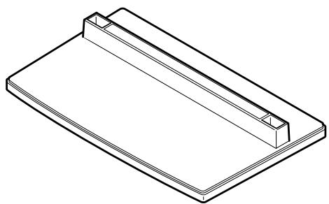
- Base cover x 1
- Screws (4 × 8) × 4

- Stand pipes (left and right, interchangeable) x 2
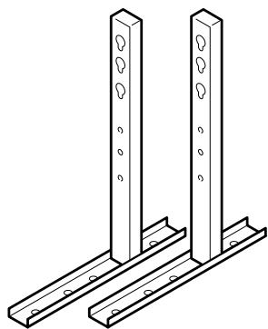
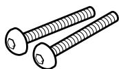
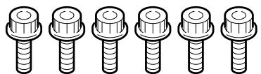
Installation bolts 1 (M8 x 20) x 2

Installation bolts 2 (M8 x 40) x 2
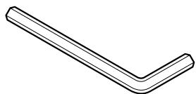
- Hexagonal wrench x 1
- Stabilization bolts x 2

Usage cautions to ensure correct usage
Symbols
The following symbols are used to ensure safe usage of the product, to prevent danger to yourself and other parties and to prevent damage to property.

WARNING
This symbol indicates that incorrect handling due to ignoring this symbol can result in the possibility of personal injury or even death.

CAUTION
This symbol indicates that incorrect handling due to ignoring this symbol can result in the possibility of personal injury and physical damage.


This symbol indicates additional cautions (including warnings).
This symbol indicates forbidden actions.
This symbol indicates required actions.

Caution (general)

Forbidden (general)

Required (general)

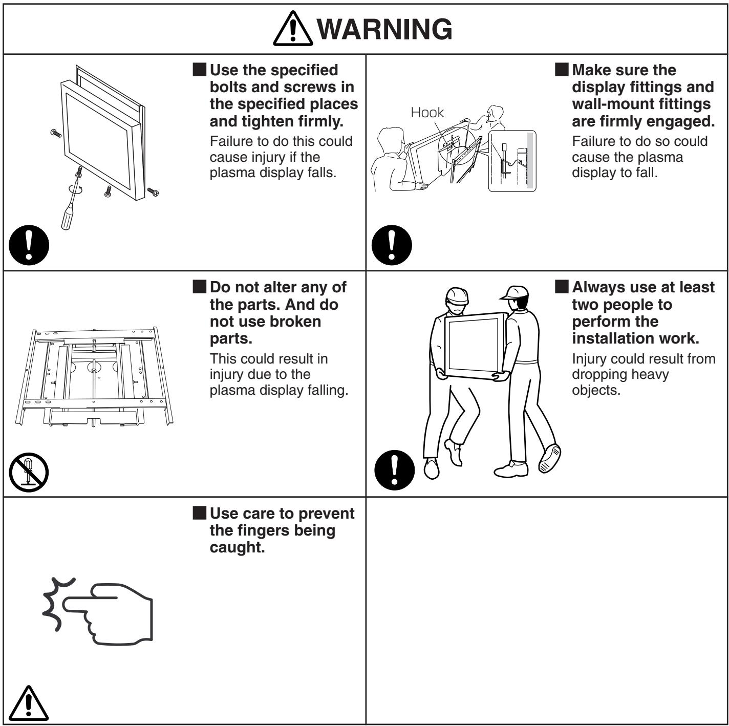
WARNING

Always use at least two people to perform the installation work.
Injury could result from dropping heavy objects.
Use the specified bolts and screws in the specified places and tighten firmly.
Failure to do this could cause injury if the plasma display falls.

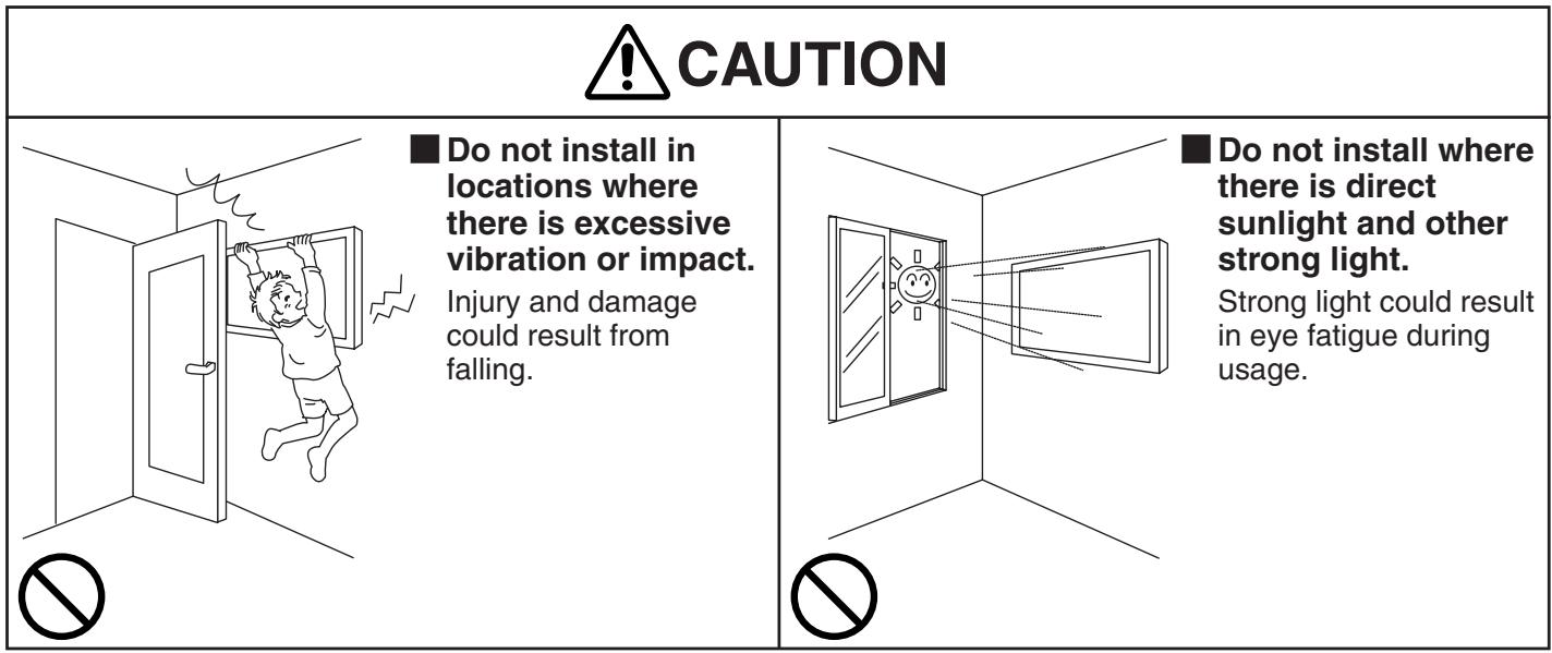
CAUTION
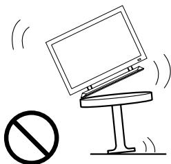
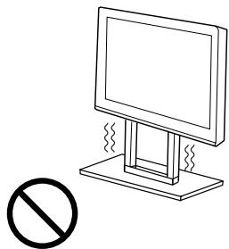
Do not mount the plasma display in an instable place.
The display could fall or break, resulting in physical injury.
Avoid installing in locations where the temperature and humidity are excessively high, and where contact with water is possible.
These can result in fire or electrical shock.
Do not block the ventilation holes. Also provide sufficient clearance in regard to avoid blocking the ventilation.
The internal temperature could elevate and possibly result in fire.
Do not alter any of the parts. And do not use broken parts.
This could result in injury due to the plasma display falling.
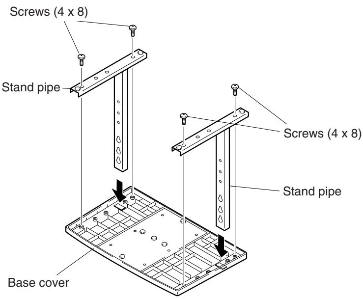
Stand assembling
■ Assembling Steps
- Turn the base cover over so the underside is facing up.
- Insert the stand pipes into the base cover.
- Use the included screws to stabilize the stand pipes.
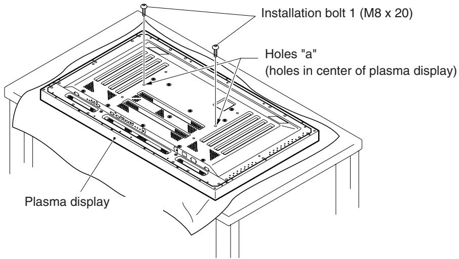
Stand attaching to the Plasma Display
■ Normal Installation
Step 1. With the plasma display lying flat, insert and secure the two Installation bolts 1 (M8 x 20) in the holes "a" located in the plasma display housing.
At this point, tighten these bolts 1 only until the threads are no longer visible when viewed from t he side (you will be unable to attach the display if the bolts are screwed in completely).
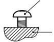
Installation bolt 1
Plasma display housing

Stop screwing down the bolt when the threads are no longer visible.
Regarding the stand pipe screw holes when the stand is used as a desktop stand

| Specifications | Screw holes used with stand orientation |
| Normal use | B, B' |
| With optional speakers attached to both sides of display |
Stand attaching to the Plasma Display
Step 2. As shown in figure, hook the stand pipe holes onto the screw heads of the installation bolts 1, then slide the stand upwards to the main plasma display until it engages the installation bolts 1 (once put together with the display, the stand will slides no more than 19mm (3/4 inch)).
Step 3. Pass the installation bolts 2 (M8 x 40) through the stand pipes and tighten the installation bolts securely with the included hexagonal wrench.
Step 4. Tighten the installation bolts 1 securely with the hexagonal wrench provided.
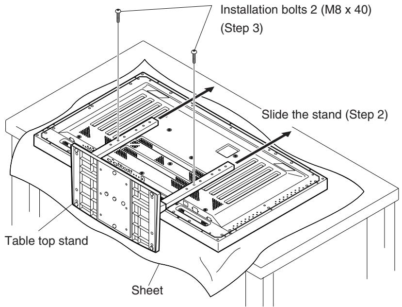
Notes
- Place a sheet or protective cover to protect the display from scratches or damage.
- Assemble only with the plasma display lying flat on a table or similar surface.
- Insert the bolts vertically in the holes and tighten them, but do not apply excessive pressure that tightens them more than necessary.
- Move the stand so that the stand screw holes and the nuts that connect the main display line up correctly.
- The display is a 50^ model that weighs approximately 40 kilograms (88 lb) and has little depth, making the display very unstable. For this reason, at least two people are required for setup and installation.
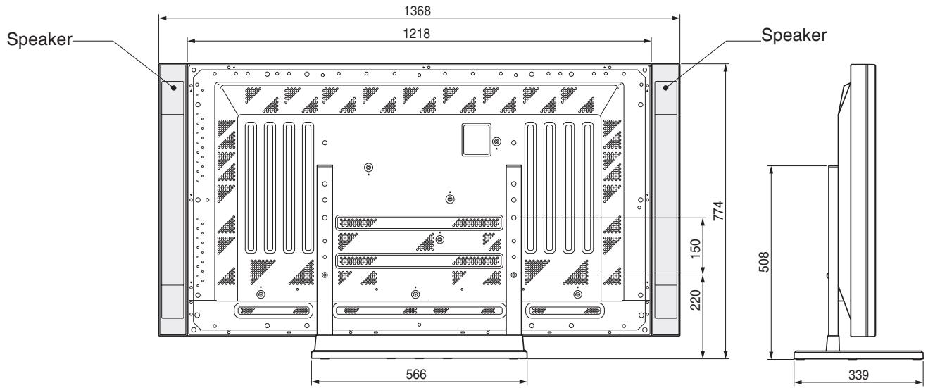
■ Instructions for using the main display packing material as a stand for the working on the display
Main plasma display packaging setup
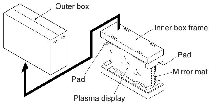
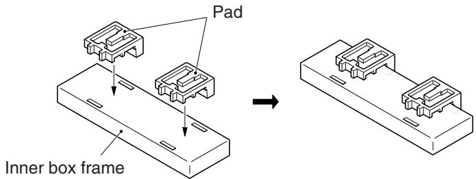
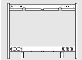
Step 1. Construct the stand for the plasma display using the inner box frame and pads shown in the figure above (all pads are identical). Pad
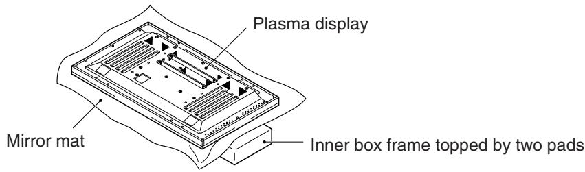
Step 2. Set the plasma display down on the pads as shown in the figure below.
Step 3. Follow the instructions in Steps 1-4 in "Normal Installation" to attach the stand to the plasma display.
After assembling, connect the stand to the floor to prevent from falling over.
Stabilizing to the floor
- Use screws (sold separately) to attach and stabilize the stand.
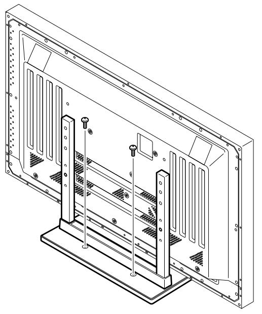
Sample use of the stabilization bolts
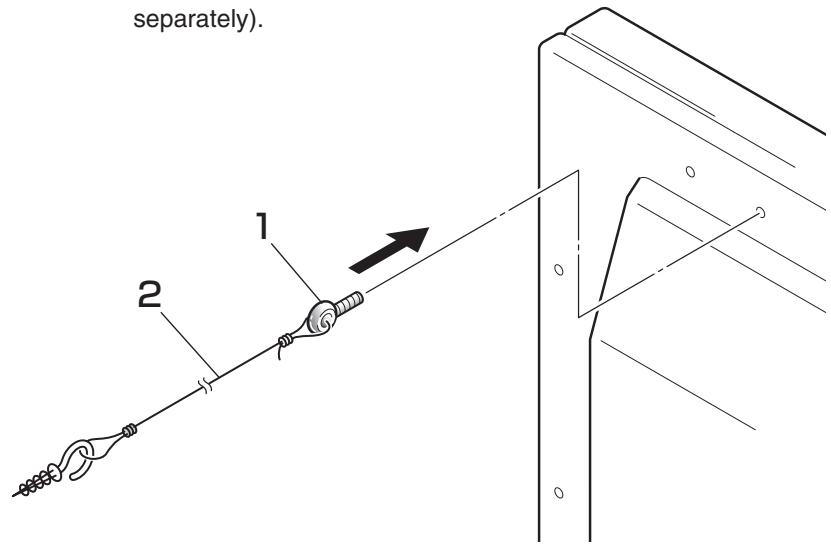
- Attach the stabilization bolts that come with the plasma display.
- Stabilize the display by connecting to a wall or standing beam with a strong cord.
(Repeat the same steps in the laterally direction to stabilize the assembly to the left and right.)
Use cord and hooks that are available on the market (sold separately).
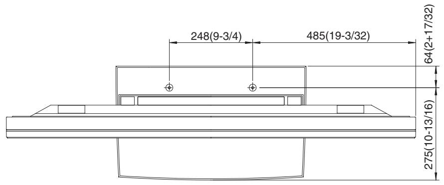
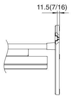
Installation coordinates for screws used to stabilize the stand to the floor
- When stabilizing the stand to the floor, use M6 with a length above 20 mm (25/32 inch). Units: mm (inch)
Specifications
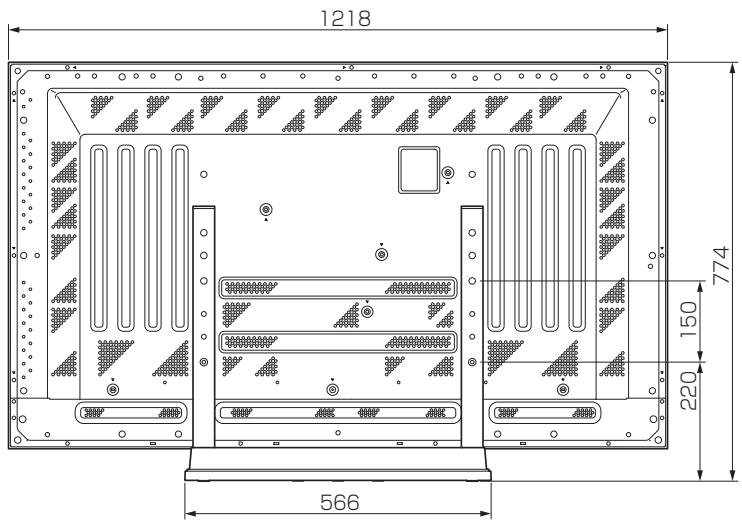
| Dimensions | 566 (W) x 508 (H) x 339 (D) mm (22-5/16 (W) x 20 (H) x 13-3/8 (D) in.) |
| Weight | 4.0 kg (8.82 lb) 42.9 kg (94.58 lb) (When the 50 inch plasma display is attached) |
| Main material/ Surface treatment | Steel sheet ABS |
Dimensions Diagram
Normal use (without optional speakers)
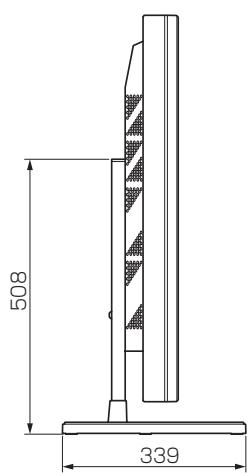
Optional speakers attached to both sides of display
HITACHI
Hitachi Plasma Display Wall-mount Unit
Model
CMPAK06
Installation Instructions
Thank you for purchasing the Hitachi Plasma Display Wall-mount Unit.
To ensure correct usage, please read this instruction manual thoroughly. After reading, please store this manual in a safe place for future reference.
©This plasma display wall-mount unit is for use only with the following model:
CMP5000WX
Special techniques are necessary for installation of the plasma display.
Do not attempt to perform this work by yourself.
■ Request an installation specialist to install this unit.
This company assumes absolutely no responsibility for injuries and damages that may occur due to improper installation and handling.
Please remember that if you remove the plasma display set from the wall later, you will find the screw holes and anchor bolts for the mounting unit left on the wall. Also note that a long use of the plasma display set may discolor the wall around it due to its heat and air flow.
To dealers and shops
- To ensure customer safety, be sure to design the installation location so that the strength is sufficient to withstand the weight of both the plasma display and the wall-mount unit.
- Always use at least two persons for all installations.
- Fully tighten all of the mounting screws as specified in the installation instructions.
Parts Configuration Chart
■Confirming the parts provided
Before assembly, check to make sure that none of the parts provided are missing.
- Screws to be used for wall installation are not included. Obtain them separately.
Hung on wall unit (1)
Bolts M8 (6)
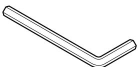
Hexagon wrench (1)
Usage cautions to ensure correct usage
Symbols
The following symbols are used to ensure safe usage of the product, to prevent danger to yourself and other parties and to prevent damage to property.

WARNING
This symbol indicates that incorrect handling due to ignoring this symbol can result in the possibility of personal injury or even death.

CAUTION
This symbol indicates that incorrect handling due to ignoring this symbol can result in the possibility of personal injury and physical damage.

This symbol indicates additional cautions (including warnings).

Caution (general)

This symbol indicates forbidden actions.

Forbidden (general)

Disassembly prohibited

This symbol indicates required actions.

Required (general)

Indicates that the power plug is to be disconnected from the power outlet.
Safety Cautions

WARNING

Disconnect the power plug from the power outlet.

Contact your local dealer.
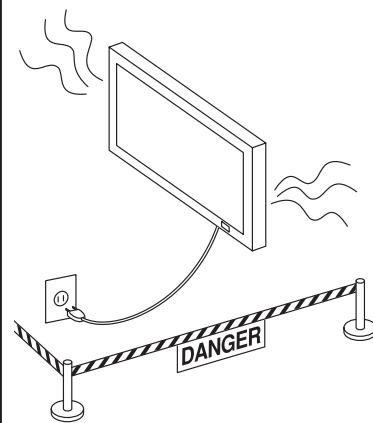
■When a malfunction occurs, disconnect the power plug from the power outlet and take measures to prevent other people coming near the plasma display.
In the cases such as
- The plasma display is loose and vibrates to an extreme degree,
- Mounting screws or parts are loose or missing,
failure to take appropriate actions can result in injury.
Perform the following actions immediately whenever a malfunction occurs.
①Turn off the plasma display power switch.
② Disconnect the power plug from the power outlet.
③ Surround the area with rope, etc., to prevent other people coming near.
④ Contact your local dealer.

Handling by other than professional contractors is prohibited.
■ Ask your dealer to install, move or adjust the wallmount unit.
Incorrect installation or adjustment can cause the plasma display to fall.

WARNING


The wall where the wall-mount unit is to be installed must be capable of long-term support of the total load of the plasma display and wall-mount unit. Measures should also be taken to ensure sufficient strength to withstand the force of earthquakes, vibration and other external forces.
Incorrect installation can cause the plasma display to fall and cause injury.
Model 50 Total load of the (plasma display + wall-mount unit) = 52.7kg
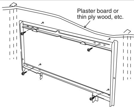
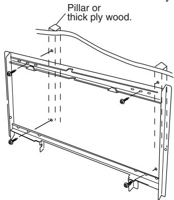
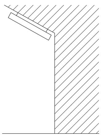
- Installation on a wooden wall
Always install so that the load is supported by a piller. If the strength of the piller is insufficient, add reinforcement. Do not install on plasters or decorative posts.
- Installation on a concrete wall
Use commercially available anchors that are capable of fully supporting the load of the plasma display.

CAUTION
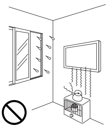
Avoid installing in locations where the temperature and humidity are excessively high, and where contact with water is possible.
These can result in fire or electrical shock.
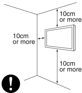
Do not block the ventilation holes. Also provide sufficient clearance in regard to the surroundings to avoid blocking the ventilation.
The internal temperature could elevate and possibly result in fire.
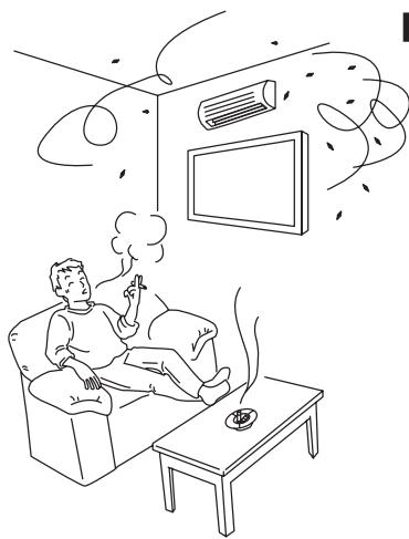
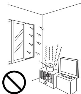
Do not install close to an air-conditioner intake or outlet.
Do not install in locations where there is excessive amounts of dust, oily smoke or tobacco smoke.
Fire could result.
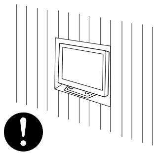
Mount only on a vertical, rigid wall surface.
The internal temperature could elevate and possibly result in fire. Injury or damage could also result from falling.


Installing
Installation Method
Installation procedure
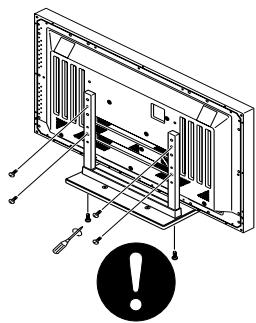
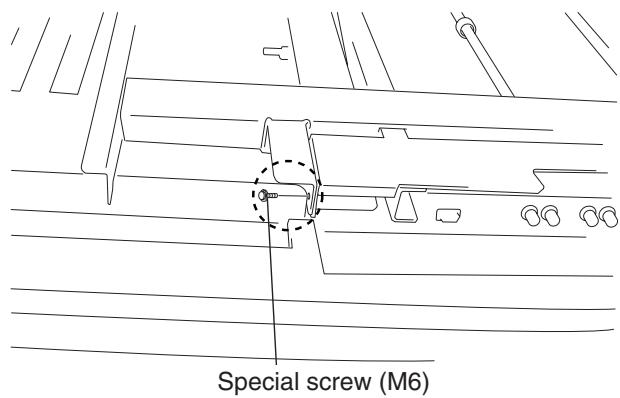
1 Remove the special screws (2 locations) from the bottom of the hung on wall unit.
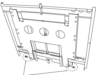
Special screws (M6)
2 Remove the hardware on the wall side and the hardware on the PDP side.
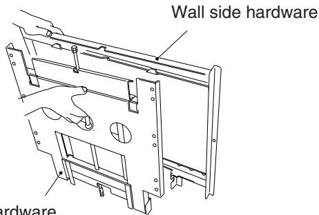
PDP side hardware
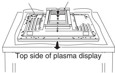
3 Attach the PDP side hardware to the plasma display.
Warning
- Cover the display with a sheet or similar protective material to protect it from scratches or other damage.
- Be sure to attach it on top of a flat table or similar surface.
Plasma display
PDP side hardware
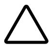
Fix the plasma display to the PDP side hardware with bolt M8 (6 locations). Usually, use the holes marked with the red triangle "△".

Top side of plasma display
Warning
Be sure to install the speaker at this stage.
- For the installation method, refer to the speaker installation procedure in the speaker user manual.
5 Attach the wall side hardware to the wall. Install the wall side hardware (4 locations) symmetrically on the left and right side (one at each location from the center of the ). Because the screws and bolts used to do this are different according to the wall strength and wall material, purchase suitable screws and bolts separately.
Warning
Check the strength of the wall and beams before installing the display.
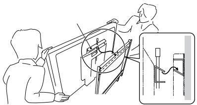
6 Attach the hook on the PDP side hardware to the wall side hardware.
Warning
Do not hold the speakers during the installation work.
7 Fix the bottom of the hardware with the special screws removed at step 1 (one on the left and one on the right).
Installation Method
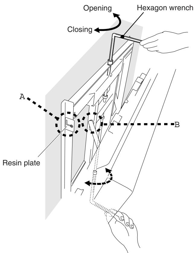
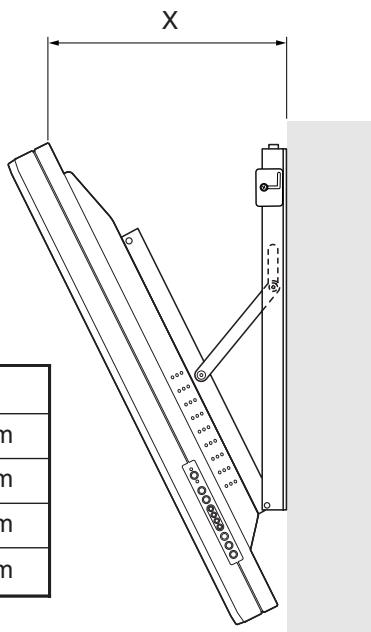
Angle setup
This installation hardware allows the display to be directed downwards freely at any angle from the vertical to 25^ .
This adjustment must always be done by 2 people.
Adjust the angle by rotating the screws at the center top and center bottom of the wall side hardware to the left or right.
Warning
If the angle is increased while you are adjusting the angle using the screw at the center of the bottom, it is difficult to turn the screw. When this happens, adjust it at the center of the upper.
- Turn the screws very carefully to avoid damaging the wall.
- When a screw becomes tight at either end of the adjustment range, do not turn the adjustment screw any further, because if you do, you will apply excessive force, deforming the screw.
(A) Criterion for the vertical location
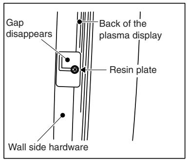
When it is in this state, do not turn the adjustment screw any further in the closing direction.
(B) Criterion when its angle is 25^
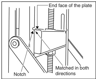
When it is in this state, do not turn the adjustment screw any further in the opening direction.
Measuring the opening distance X enables approximate angle values to be determined.
Tilt Angle Criteria
| Angle | X |
| 5° | 133mm |
| 10° | 188mm |
| 15° | 241mm |
| 20° | 291mm |
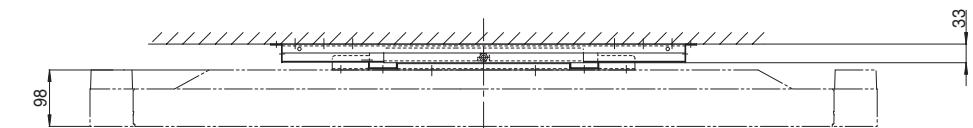
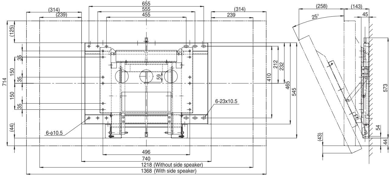
Product Specifications
External Dimensions
| Mass | 13.8kg |
| Main material | Steel sheet |
| Surface treatment | Black baked paint |
| Products mounted | CMP5000WX |
HITACHI
Speaker Systems for Hitachi Plasma Display Monitor CMP5000WX
Model
CMPAS05
User Manual
READ THE INSTRUCTIONS ON THIS USER MANUAL CAREFULLY.
KEEP THIS USER MANUAL FOR FUTURE REFERENCES.
CAUTION
DO NOT HANDLE THE MONITOR BY HOLDING THE SPEAKER SYSTEMS.
CAUTION
Please handle the speakers with sufficient care, as the grille net and the cabinet can become damaged or broken when they are subjected to strong external impacts.
Parts Configuration Chart
■Confirming the parts provided
Before assembly, check to make sure that none of the parts provided are missing.
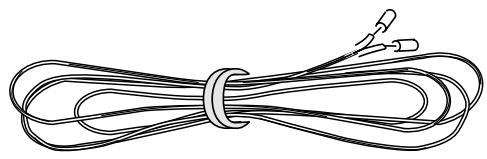
- Speaker cable (27 cm) x 2

- Speaker mounting bolts
Flat countersunk head screw x 4
Hexagon socket head screw x 4
Washer M8 ( 25 ) x 2

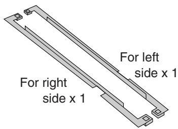
- Mounting plate
- Speaker mounting fittings
For top right
side x 1
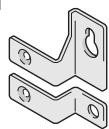
For top left side x 1
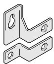
For bottom x 2
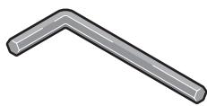
- Mounting tool (Hex wrench)
NOTE:
Always use the accessory mounting fittings for installation.
- When screws other than those enclosed as accessories are used to install the speakers, the speakers may drop off or accidents may be caused. Always use the screws enclosed as accessories.
Installation on the plasma display
Perform installation according to the following steps 1 to 3.
NOTE:
After this unit has been installed on the plasma display, you can't use the display operation panel. Please use the remote control supplied with the display.
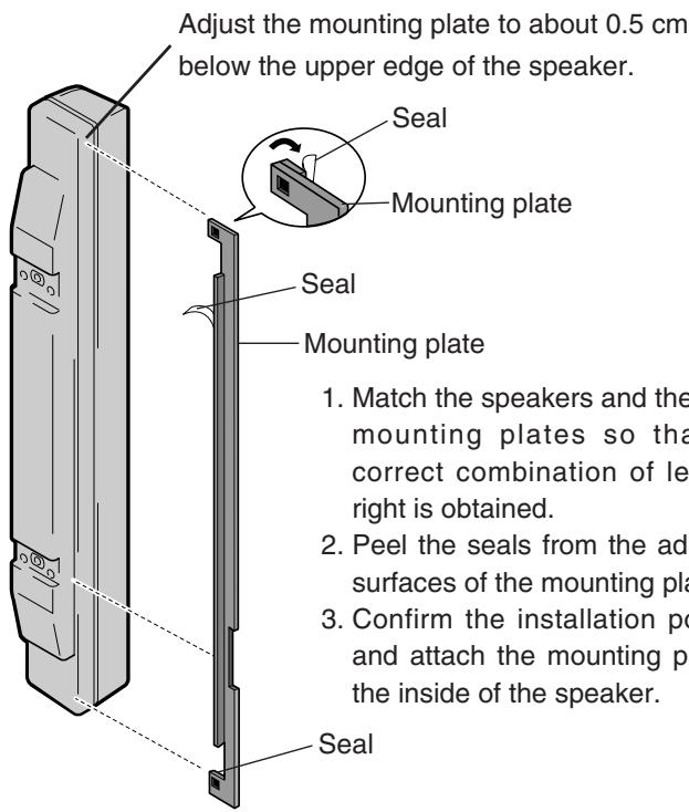
1. Attach the mounting plates to this unit
As in the illustration below (right speaker only), when looking from the rear, attach the right mounting plate to the right hand side of the right speaker. For the left speaker, attach the left mounting plate to ther left hand side.
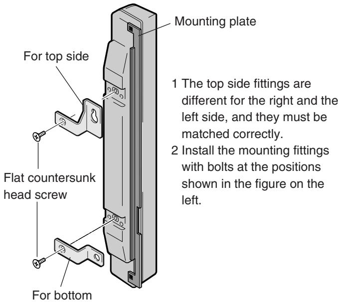
2. Install the mounting fittings on this unit
The illustration shows an example for this unit (right side).
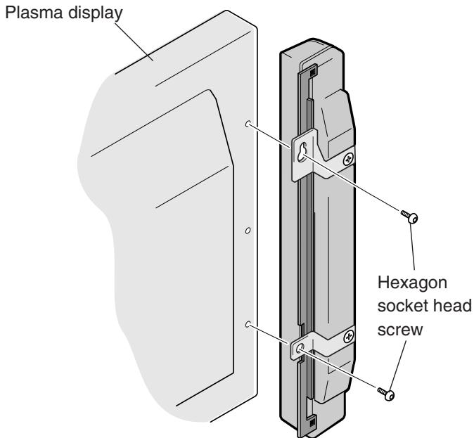
3. Install this unit on the display side
Install the unit marked "RIGHT" on the right side of the display.
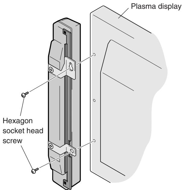
Install the unit marked "LEFT" on the left side of the display.
- Check the indications LEFT and RIGHT at the rear of the speakers, observe the indication "UP", and fasten the upper mounting fitting provisionally to the display. Then install the lower fitting on the display.
- Adjust the position so that the gap between the speaker and the display is uniform, and then tighten the screws firmly.
CONNECTION TO A
Plasma Display
- Switch off the power of the plasma display.
- Connect the input terminals of the speaker system and the speaker output terminals of the plasma display with the accessory speaker cable.
The polarity of the input terminals is plus (+) for the red terminal (the terminal on the right side in the following figure) and minus (-) for the black terminal (the terminal on the left side in the following figure).
1.Remove the insulation and twist the core ends together.

2.Push the lever, insert the cable into the hole, and release the lever.
Minus terminal Plus terminal
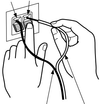
Minus terminal
Plus terminal
Speaker output terminals of the plasma display.

- After connection to the terminals, pull lightly on the cable to confirm that the tips of the cable are connected positively to the terminals. An imperfect connection can cause sound interruptions and noise.
- When cable cores stick out and + and - lines are short-circuited, an excessive load will be applied to the plasma display and the operation will stop or trouble will be caused.
Installation to commercial
mounting fittings
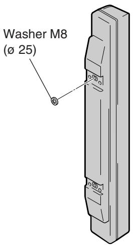
This unit includes M8 (ø 25) washers for installation on commercial mounting fittings. Installation is made by two-point fixing at the top side mounting holes for commercial mounting fittings. As these two mounting holes are not at the same level, washers are used to compensate for this difference.
MAINTENANCE
- Use a polishing cloth or dry cloth to wipe off dust and dirt.
- When the cabinet is very dirty, wipe with a soft cloth moistened with water-diluted cleanser; then wipe again with a dry cloth. Do not use furniture wax or cleaners. They may damage the surface of the cabinet.
- Never use thinner, benzine, insecticide sprays and other chemicals on or near the cabinets, since these will corrode the surfaces.
- When a chemical cloth is used, read the cautions for the chemical cloth carefully.
SPECIFICATIONS
Cabinet: Enclosed type
Used speakers (two-way method):
Woofer (for low tones) . . . . . . . . . . . . . . . . . . . . . . . . . . . . . . . . . . . . . . . . . . . . . . . . . . . . . . . . . . . . . . . . . . . .
Tweeter (for high tones) 2.5 cm dome type
Nominal impedance 8Ω
Frequency Range 50 to 20,000 Hz
Sensitivity 82 dB/W (at 1 m distance)
Permissible input :
Max. input 12 W
Rated input 4 W
Crossover frequency 3 kHz
External Dimensions. 74 (W) x 714 (H) x 101 (D) mm
Weight. 1.8 kg
Accessory parts (for 2 speakers)
Speaker cable x 2, Flat countersunk head screw x 4, Hexagon socket head screw x 4, Mounting tool x 1, Washer M8 (ø 25) x
2, Speaker mounting fittings (for top left side) x 1, Speaker mounting fittings (for top right side) x 1, Speaker mounting fittings (for bottom) x 2, Mounting plate (for left side) x 1, Mounting plate (for right side) x 1, User Manual x 1
Specifications and design subject to possible modification without notice, due to improvements.
HITACHI
Hitachi, Ltd. Tokyo, Japan
International Sales Division
THE HITACHI ATAGO BUILDING,
No. 15-12 Nishi Shinbashi, 2-Chome,
Minato - Ku, Tokyo 105-8430, Japan.
Tel: 03 35022111
HITACHI EUROPE LTD.
Dukes Meadow
Millboard Road
Bourne End
Buckinghamshire
SL85XF
UNITED KINGDOM
Tel: 01628 643000
Fax: 01628 643400
Email: consumer-service@hitachi-eu.com
HITACHI EUROPE S.A.
364, Kifissias Ave. & 1, Delfon Str.
15233Chalandri
Athens
GREECE
Tel: 1-6837200
Fax: 1-6835694
Email: service.hellas@hitachi-eu.com
HITACHI EUROPE GmbH
Munich Office
Dornacher Strasse 3
Email: customerservice.italy@hitachi-eu.com
HITACHI EUROPE S.A.S
Lyon Office
B.P. 45, 69671 Bron Cedex
FRANCE
Tel: 04 72 14 29 70
Fax: 0472142999
Norwegian Branch Office
Strandveien 18
1366 Dysaker
NORWAY
Tel: 02205 9060
Fax: 02205 9061
Email csgnor@hitachi-eu.com
ITEM N.V./S.A. (INTERNATIONAL TRADE FOR
ELECTRONIC MATERIAL & MEDIA N.V./S.A)
UCOTower-Bellevue,17
B-9050 GENT
BELGIUM (for BENELUX)
Tel: 092304801
Fax: 092309680
Email: hitachi.item@skynet.be