
CPSX5600W - Projector HITACHI - Free user manual and instructions
Find the device manual for free CPSX5600W HITACHI in PDF.

| Product type | Liquid crystal projector |
| Brand | Hitachi |
| Model | CPSX5600W |
| Display technology | Active matrix TFT LCD |
| Native resolution | 1365 x 1024 pixels (SXGA+) |
| Lens | Zoom F=2.7-3.1 f=38-49 mm |
| Lamp | 220 W UHB (lamp life approx. 1300 hours) |
| Built-in speaker | 1 W (mono) |
| Dimensions (W x H x D) | 250 x 103 x 335 mm |
| Weight | 5.6 kg |
| Power supply | 100-120 V AC / 220-240 V AC (automatic selection) |
| Power consumption | 360 W |
| Video inputs | RGB IN 1 (D-sub 15), RGB IN 2 (D-sub 15), DVI-D, S-Video (mini DIN 4-pin), Composite video (RCA), Component (Y, Cb/Pb, Cr/Pr via RCA) |
| Audio inputs | Stereo mini jack for RGB 1/DVI and RGB 2; RCA (L/R) for video |
| Outputs | RGB OUT (D-sub 15), AUDIO OUT (stereo mini jack) |
| Main functions | Keystone correction (vertical/horizontal), digital zoom, manual focus, freeze image, magnification, picture-in-picture (PIP), silent mode, image adjustments (brightness, contrast, sharpness) |
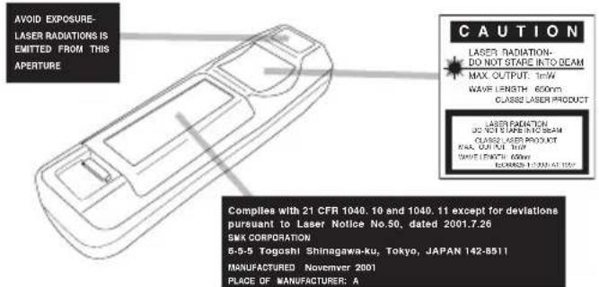
| Remote control | With laser pointer and AA batteries |
| Security | Automatic shut-off when no signal, password lock (menu), overheat protection |
| Maintenance | Clean air filter every 300 hours, replace lamp (DT00421) and air filter (MN04291) |
| General information | User manual available in French, 73 pages |
Frequently Asked Questions - CPSX5600W HITACHI
User questions about CPSX5600W HITACHI
0 question about this device. Answer the ones you know or ask your own.
Ask a new question about this device
Download the instructions for your Projector in PDF format for free! Find your manual CPSX5600W - HITACHI and take your electronic device back in hand. On this page are published all the documents necessary for the use of your device. CPSX5600W by HITACHI.
USER MANUAL CPSX5600W HITACHI
Please read this user's manual thoroughly to ensure correct usage through understanding.
Thank you for purchasing this liquid crystal projector.
WARNING · Please read the accompanying manual "SAFETY INSTRUCTIONS" and this "USER'S MANUAL" thoroughly to ensure correct usage through understanding. After reading, store this instruction manual in a safe place for future reference.
NOTE The information in this manual is subject to change without notice.
- The manufacturer assumes no responsibility for any errors that may appear in this manual
- The reproduction, transmission or use of this document or contents is not permitted without express written authority.
TRADEMARK ACKNOWLEDGMENT: PS/2, VGA and XGA are registered trademarks of International Business Machines Corporation. Apple, Mac and ADB are registered trademarks of Apple Computer, Inc. VESA and SVGA are trademarks of the Video Electronics Standard Association. Windows is a registered trademark of Microsoft Corporation. Carefully observe the trademarks and registered trademarks of all companies, even when not mentioned.
CONTENTS
Page
FEATURES 2
BEFORE USE 2
Contents of Package 2
Part Names. 3
Loading the Batteries. 5
INSTALLATION 6
Installation of the Projector and Screen.....6
Angle Adjustment 6
Cabling 7
Power Connection 8
Example of System Setup 8
Plug & Play. 8
OPERATIONS. 9
Power On 9
Power Off 9
Basic Operation. 10
Setup Menu 12
Input Menu. 13
Image Menu. 14
Options Menu 15
No Signal Menu. 16
MAINTENANCE 17
Lamp. 17
Air Filter 19
Other Maintenance. 19
Page
TROUBLESHOOTING 20
OSD Message 20
Indicators Message 21
Symptom 22
SPECIFICATIONS. 23
WARRANTY AND AFTER-SERVICE.....24
TABLES
Table 1. Installation Reference..
Table 2. Cabling .7
Table 3. Basic Operation.. 10
Table 4. Setup Menu 12
Table 5. Input Menu.. 13
Table 6. Image Menu.. 14
Table 7. Options Menu 15
Table 8. No Signal Menu. 16
Table 9. OSD Message 20
Table 10. Indicators Message 21
Table 11. Symptom 22
Table 12. Specifications 23
For "TECHNICAL" and "REGULATORY
NOTICE", see the end of this manual.
This liquid crystal projector is used to project various computer signals as well as NTSC / PAL / SECAM video signals onto a screen. Little space is required for installation and large images can easily be realized.
Outstanding Brightness
The UHB lamp and high-efficiency optical system assure a high level of brightness.
Partial Magnification Function
Interesting parts of images can be magnified for closer viewing.
Distortion Correction Function
Distortion-free images are quickly available.
Extra-low Noise Function
Acoustic noise level from the unit can be reduced.
BEFORE USE
Contents of package
Make sure all of the following items are included in the package. If anything is missing, please contact your dealer.
NOTE - Keep the original packing material for future reshipment.
Projector (with Lens Cap)
User's Manual (this manual)
Safety Instructions
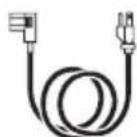
Power Cord (US Type)
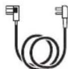
Power Cord (UK Type)
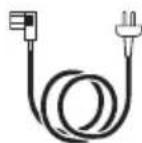
Power Cord (Europe Type)
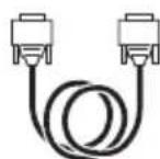
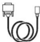
RGB Cable Video/Audio Cable (with white lead)
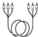
Component Video Cable (with green lead)
Mouse cable (PS/2)
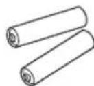
Batteries for Remote Control Transmitter
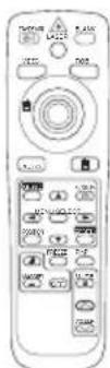
Remote Control Transmitter
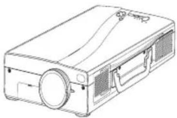
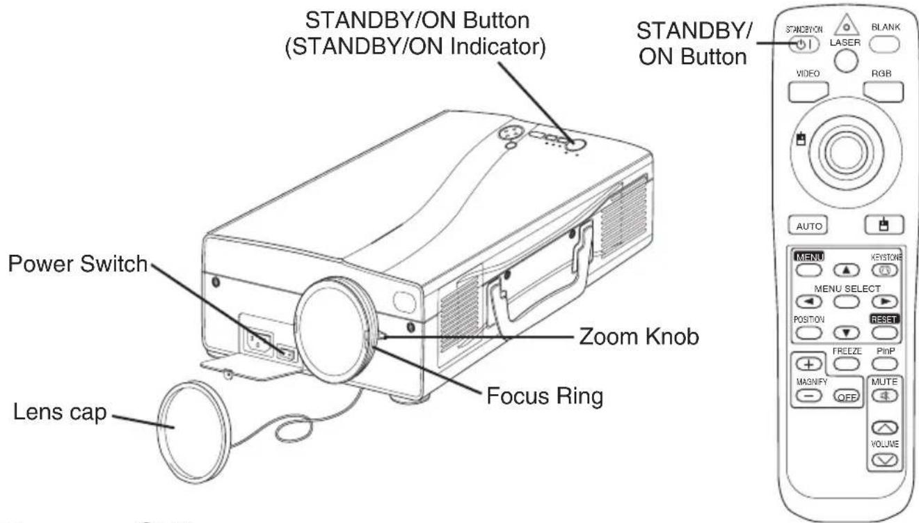
Part Names
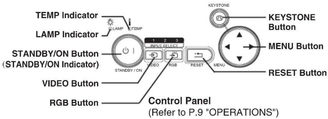
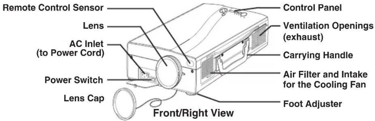
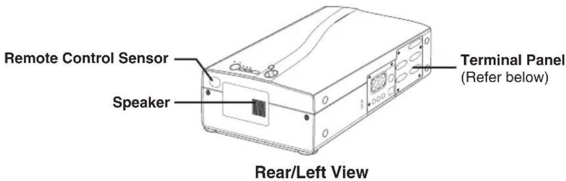
Part Names (continued)
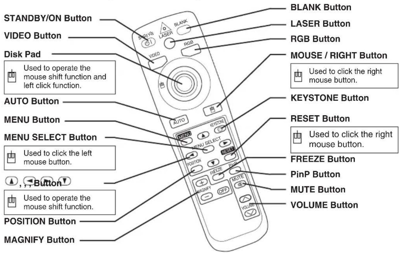
REMOTE CONTROL TRANSMITTER
(Refer to P.9 "OPERATIONS")
These functions work when the mouse control function is activated. Remember, the POSITION, BLANK ON and MENU ON functions disable the mouse control function.

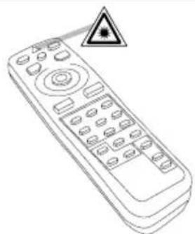
WARNING • The laser pointer of the remote control transmitter is used in place of a finger or rod. Never look directly into the laser beam outlet or point laser beam at other people. The laser beam can cause vision problems.
NOTE - Keep the remote control transmitter away from children and pets.
- Do not give the remote control transmitter any physical impact. Take care not to drop.
- Do not place the heavy objects on the remote control transmitter.
- Do not wet the remote control transmitter or place it on any wet object.
- Do not place the remote control transmitter close to the cooling fan of the projector.
- Do not disassemble the remote control transmitter.
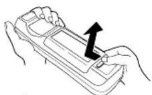
Loading the Batteries
Install the AA batteries into the remote control transmitter.
- Remove the battery cover. Push the knob while lifting up the battery cover.
- Load the batteries.
Make sure the plus and minus poles are correctly oriented.
- Close the battery cover.
1
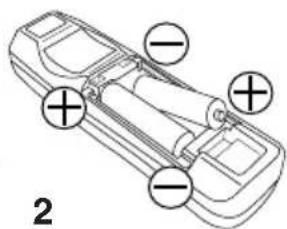
CAUTION • Use only the specified batteries with this remote control transmitter. Also, do not mix new and old batteries. This could cause battery cracking or leakage, which could result in fire or personal injury.
- When loading the batteries, make sure the plus and minus terminals are correctly oriented as indicated in the remote control transmitter. Incorrect orientation could cause battery cracking or leakage, which could result in personal injury or pollution of the surrounding environment.
- When you dispose the battery, you should obey the law in the relative area or country.
- Keep the battery away from children and pets.
- When not to be used for an extended period, remove the batteries from the remote control transmitter.
NOTE Replace the batteries when remote control transmitter operation becomes difficult.
Installation of the Projector and Screen
Refer to the drawing and table below for determining the screen size and projection distance.
The projection distances shown in the table below are for full size (1365 x 1024 dots).
a: Distance from the projector to the screen. (± 10%)
Table 1. Installation Reference
| Screen size [inches (m)] | a[inches (m)] | |
| Min. Max. | ||
| 40 (1.0) 65 | (1.6) 85 (2.2) | |
| 60 (1.5) 98 | (2.5) 127 (3.2) | |
| 80 (2.0) 131 | (3.3) 170 (4.3) | |
| 100 (2.5) 164 | (4.2) 213 (5.4) | |
| 120 (3.0) 196 | (5.0) 255 (6.5) | |
| 150 (3.8) 246 | (6.2) 319 (8.1) | |
| 200 (5.0) 328 | (8.3) 426 (10.8) | |
CAUTION • Install the projector in a suitable environment according to instructions of the accompanying manual “SAFETY INSTRUCTIONS” and this manual.
- When you fix this unit with a metal tool and the like, you must connect it with ground wire; otherwise, fire or electric shock can result.
Connect the ground terminal of AC inlet of this unit with the ground terminal provided at the building using an optional three-core power-supply cord. - Please basically use liquid crystal projector at the horizontal position. If you use liquid crystal projector by the lens up position, the lens down position and the side up position, this may cause the heat inside to build up and cause damage. Be especially careful not to install it with ventilation holes blocked.
- Do not install LCD projector in smoke effected environment. Smoke residue may buildup on critical parts (i.e.LCD panel, Lens Assy etc.).
Angle Adjustment
Use the foot adjusters on the bottom of the projector to adjust the projection angle. It is variable within 0^ to 8^ approximately.
- Lift up the front side of the projector, and pressing the foot adjuster button, adjust the projection angle.
- Release the button to lock at the desired angle.
- Use the foot adjusters for fine adjustment, Do not force the foot adjuster screws. This could damage the adjusters or cause the lock to fail.
Variable within the range of approximately 0^ - 8^
CAUTION · Do not release the foot adjuster button unless the projector is being held; otherwise, the projector could overturn or fingers could get caught and cause personal injury.
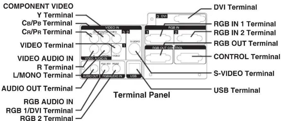
Cabling
Refer to the table below for connecting each terminal of the projector to a device.
Table 2. Cabling
| Function Terminal | Cable | |
| Analog RGB input | RGB IN 1 | RGB cable with D-sub 15-pin shrink jack and inch thread screws |
| RGB IN 2 | ||
| Analog RGB output RGB OUT | ||
| DVI input DVI DVI cable with inch thread screws | ||
| Audio input(from the computer) | RGB AUDIO IN [RGB 1 / DVI](interlocked with RGB IN 1 or DVI) | Audio cable with stereo mini jack |
| RGB AUDIO IN [RGB 2](interlocked with RGB IN 2) | ||
| PS/2 mouse control | cableCONTROL | PS/2 mouse cable |
| ADB mouse control ADB mouse | cableCONTROL | |
| Serial mouse control Serial mouse | cable | |
| RS-232C communication RS-232 | 2C cable | |
| USB mouse control USB | USB cable | |
| S-video input | S-VIDEO | S-video cable with mini DIN 4-pin jack |
| Video input | VIDEO | Video/Audio cable |
| Component video input | COMPONENT VIDEO [Y] | Component Video cable |
| COMPONENT VIDEO [Cb/Pb] | ||
| COMPONENT VIDEO [Cr/PR] | ||
| Audio input(from video equipment) | AUDIO [L / MONO] | Video/Audio cable or Audio cable with RCA jack |
| AUDIO [R] | ||
| Audio output | AUDIO OUT | Audio cable with stereo mini jack |

CAUTION • Incorrect connecting could result in fire or electrical shock.
Please read this manual and the separate "SAFETY INSTRUCTIONS".
- Before connecting, turn off to all devices to be connected, except for the USB cable.
- The cables may have to be used with the core set to the projector side. Use the cables which are included with the projector or specified.
NOTE - Before connecting, read instruction manuals of the devices to be connected, and make sure that the projector is compatible with the device.
- Secure the screws on the connectors and tighten.
- For some RGB input modes, the optional Mac adapter is necessary.
To select the DVI input, the computer may need some settings. See the manuals of the computer for details. - Some computers may have multiple display screen modes. Use of some of these modes will not be possible with this projector.
Refer to the "TECNCAL" section for the pin assignment of connectors and RS-232C communication data. - When the DVI terminal is used, the RGB OUT terminal may not function.
Power Connection
Use the correct power cord depending on the power outlet to be used. Connect the AC inlet of the projector to the power outlet firmly by the power cord.
Example of System Setup
NOTE - When connecting with a notebook computer, set the proper RGB external image output (setting CRT display or simultaneous display of LCD and CRT). Please read instruction manual of the notebook for more information.
Plug & Play
This projector is VESA DDC 1/2B compatible. Plug & play is possible by connecting to a computer that is VESA DDC (Display Data Channel) compatible.
Please use this function by connecting the RGB cable with RGB IN 1 terminal (DDC 1/2B compatible), or by connecting a DVI cable with DVI terminal (DDC 2B compatible). Plug & play may not operate by other connections.
NOTE · Plug & play is a system configured with peripheral equipment including a computer, display and an operating system.
- This projector is recognized as a plug & play monitor. Use the standard display drivers.
- Plug & play may not operate by the computer to connect. Use the RGB IN 2 terminal if plug & play does not operate correctly.
ENGLISH
Power ON
- Check that the power cord is connected correctly.
- Set the power switch to [1]. The standby mode is selected, and the STANDBY/ON indicator is turned to orange.
- Press the STANDBY/ON button on the control panel or the remote control transmitter. Warm-up begins and the STANDBY/ON indicator blinks in green.
- The STANDBY/ON indicator ceases blinking and turns to green when power is on. Remove the lens cap.
- Adjust picture size using the Zoom Knob.
- Adjust focus using the Focus Ring.
Power OFF
- Press the STANDBY/ON button on the control panel or the remote controller. Then, the message "Power off?" will appear on the screen, and the message will disappear by any operation or no operation for 5 seconds. During this message indication, press the STANDBY/ON button again. The projector lamp is extinguished and lamp cooling begins. The STANDBY/ON indicator blinks orange during lamp cooling. Pressing the STANDBY/ON button has no effect while the STANDBY/ON indicator is blinking.
- The system assumes the Standby mode when cooling is complete, and the STANDBY/ON indicator ceases blinking and changes to orange. Check that the indicator is orange and set the Power switch to [O].
- The STANDBY/ON indicator is extinguished when power is off. Attach the lens cap. Put the Lens cap to the lens properly. In order to do it, keep pushing two knobs on the lens cap, then fit it to the lens holding the cap in horizontal position.

WARNING · Please read this manual, and the separate "SAFETY INSTRUCTIONS" thoroughly before using the equipment. Always ensure that equipment is used safely.
NOTE Except in emergencies, follow the above-mentioned procedure for turning power off. If the projector is used improperly, it may very difficult to turn off the projector caused by heating inside the unit. And the reduction of life time of lamp and LCD panels will be caused by incorrect procedure.
- To prevent any trouble, turn on/off the projector when the computer or video tape recorder is OFF. Providing a RS-232C cable is connected, turn on the computer before the projector.
- When a projector continues projecting the same image, the image may remain as an afterimage. Please do not project the image same for a long time.
Basic Operation
The basic operations shown in Table 3 is performed from the supplied remote control transmitter or the projector control panel. Items indicated by (^*) may be used from the control panel.
Table 3. Basic Operation
| Item Description | |
| INPUT SELECT (*) | Select RGB Input: Press the RGB button. VIDEO/S-VIDEO/COMPONENT VIDEO →RGB IN 1/RGB IN 2/DVI RGB IN 1 → RGB IN 2 → DVI (→ RGB IN 1) Select Video Input: Press the VIDEO button. RGB IN 1/RGB IN 2/DVI →VIDEO/S-VIDEO/COMPONENT VIDEO VIDEO → S-VIDEO → COMPONENT VIDEO (→VIDEO) ·The selected signal name is displayed for approximately 3 seconds when the input signal is changed. |
| POSITION | Set/Clear Position Adjustment Mode: Press the POSITION button. The [ ]icon is displayed in the POSITION mode. Image Position Adjustment: Press the [ ] and [ ] buttons in the POSITION mode. ·Valid only in the MAGNIFY mode with a video signal is input. ·After approximately 10 seconds of inactivity the [ ]icon is extinguished and the POSITION mode is cleared automatically. ·[ ], [ ] and [ ] buttons may operate as the mouse control button. Refer to page 4. |
| RESET (*) | Initialize Each Item: Select an item and press the RESET button. Initialize Position Adjustment: Press the RESET button and the POSITION mode. This function is valid only when RGB signal is input. ·Valid except for the VOLUME, LANGUAGE, WHISPER and H PHASE. ·The RESET button may operate as the mouse control button. Refer to page 4. |
| MAGNIFY | Set MAGNIFY Mode: Press the MAGNIFY button. Move Magnified Area: Run the POSITION in the MAGNIFY mode. Adjust Magnification: Press the MAGNIFY [ ] button in MAGNIFY mode. Clear MAGNIFY Mode: Press the MAGNIFY button. ·The MAGNIFY mode is cleared by running or setting the AUTO, ASPECT, INPUT SELECT or VIDEO, or by changing the input signal. |
| FREEZE | Set/Clear FREEZE Mode: Press the FREEZE button. The [ II ] icon is displayed, and the image is frozen, in the FREEZE mode. ·The FREEZE mode is cleared by running or setting POSITION, VOLUME, MUTE, Automatic Adjustment, BLANK ON/OFF, or MENU ON/OFF, KEystone, or by changing the input signal. ·Do not forget to clear frozen static images. |
NOTE - Use the remote control transmitter at a distance of approximately 5m from the sensor on the front of the projector, and within a range of 30^ left-right. Strong light and obstacles will interfere with operation of the remote control transmitter.
Items indicated by (^*) may be used from the control panel.
Table 3. Basic Operation (continued)
| Item Description | |
| VOLUME | Volume Adjustment : Press the VOLUME♂ / ♀ button. |
| MUTE | Set/Clear Mute Mode : Press the MUTE button. No sound is heard in the MUTE mode. |
| AUTO | Automatic Adjustment at RGB Input : Press the AUTO button. Horizontal position(H.POsiT), vertical position (V.POsiT), clock phase (H.PHASE), and horizontal size(H.SIZE) are automatically adjusted. Use with the window at maximum size in the application display. Automatic Adjustment at Video Input : Press the AUTO button. A signal type appropriate for the input signal is selected automatically. Valid only when AUTO is set for VIDEO on the menu. ·This operation requires approximately 10 seconds. It may not function correctly with some input signals. |
| BLANK ON/OFF | Set/Clear Blank Mode: Press the BLANK button. No image is displayed in the Blank mode. The screen color is as set in BLANK on the Image menu. |
| MENU ON/OFF | Menu Display Start/Stop: Press the MENU button. ·The menu display is terminated automatically after approximately 10 seconds of inactivity. |
| MENU SELECT | Select Menu Type: Press the MENU SELECT button. Allows the user to select the normal menu or the single menu. Only the selected item is displayed on the single menu, and other items are displayed with the Ⓞ and Ⓛ buttons as with the normal menu. ·Valid only when the Setup menu is used. Push the MENU SELECT button after selecting items such as "BRIGHTNESS". ·The MENU SELECT button may operate as the mouse control button. Refer to page 4. Normal menu Single menu (MENU SELECT) ←→ |
| P.IN P. MODE | Select Mode of P.IN P. Display : Press the PinP button. Small → Large → P.IN P. off (→ Small) ·P.IN P. function superimposes a video image over RGB or DVI signals. |
| KEYSTONE | Set / Clear KEYSTONE Mode : Press the KEYSTONE button. Select KEYSTONE Mode : Press the Ⓞ button in the KEYSTONE mode. Vertical Ⓞ ↔ Horizontal Adjust KEYSTONE : Press the Ⓞ button. ·The image may not be appeared properly when this function is activated on some input signals. ·The adjustable range of distortion correction will be different among input signals. |
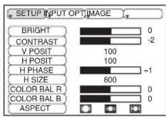
Setup Menu
The following adjustments and settings are possible when SETUP is selected at the top of the menu. Part of the Setup menu differs between RGB input and video input. Select an item with the and buttons, and start operation. Use the Single menu to reduce menu size (see Table 3, MENU SELECT).
RGB IN 1 RGB IN 2 DVI
| Item Description | RGB IN 1 RGB IN 2 | DVI | VIDEO S-VIDEO COMPONENT | |
| BRIGHT | Adjustment: Dark ≅Light ≅ | ✓✓✓ | ||
| CONTRAST | Adjustment: Weak ≅ ↔ Strong ≅ | ✓✓✓ | ||
| V POSIT | Adjustment: Down ≅Up | ✓ | - | - |
| H POSIT | Adjustment: Left ≅ ↔ Right ≅ | ✓ | - | - |
| H PHASE | Adjustment: Left ≅ ↔ Right ≅ • Adjust to eliminate flicker. | ✓ | - | ✓ |
| H SIZE | Adjustment: Small ≅ ↔ Large ≅ • The image may not be displayed correctly if the horizontal size is excessive. In such cases, press the RESET button, and initialize the horizontal size. | ✓ | - | - |
| SHARPNESS | Adjustment: Soft ≅ Clear | - | - | ✓ |
| COLOR | Adjustment: Light ≅ ↔ Dark | - | - | ✓ |
| TINT | Adjustment: Red ≅ ↔ Green ≅ • Valid only when NTSC or NTSC 4.43 signal is received. | - | - | ✓ |
| COLOR BAL R | Adjustment: Light ≅ ↔ Dark | ✓✓✓ | ||
| COLOR BAL B | Adjustment: Light ≅ ↔ Dark | ✓✓✓ | ||
| ASPECT | Select Image Aspect Ratio: Full [□] ≅ ↔ 16:9[□] ≅ ↔ Real [□] Select Position of Image: Press the ⊙ button while 16:9[□] is selected. Center → ⊙ Down → ⊙ Up (→ Center ⊙) | ✓ | ✓ | - |
| Select Image Aspect Ratio: 4:3[□] ≅ ↔ 16:9[□] ≅ ↔ 4:3 small[□] Select Position of Image: Press the ⊙ button while 16:9[□] / 4:3 small[□] is selected. Center → ⊙ Down → ⊙ Up (→ Center ⊙) • 4:3 small may not be displayed correctly with some input signals. | - | - | ✓ | |
Input Menu
The following functions are available when INPUT is selected on the menu. Select an item with the and buttons, and start or stop operation with the and buttons. The function indicated (^**) are effective on video input mode only, not on RGB input mode, except in the P.IN P. window on RGB input mode.
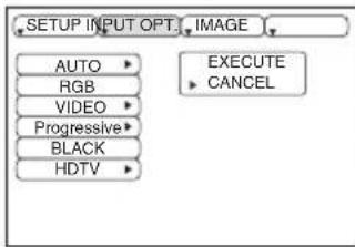
Table 5. Input Menu
| Item Description | |
| AUTO | Automatic Adjustment at RGB Input: Select the EXECUTE with the按钮. Horizontal position (H.POsiT), vertical position (V.POsiT), clock phase (H.PHASE), and horizontal size (H.SIZE) are automatically adjusted.Use with the window at maximum size in the application display Automatic Adjustment at Video Input: Select the EXECUTE with the按钮. A signal type appropriate for the input signal is selected automatically when EXECUTE is selected automatically. Valid only when AUTO is set for VIDEO on the menu.This operation requires approximately 10 seconds. It may not function correctly with some input signals. Pressing the AUTO button in this case may correct this problem.This function is the same as for the AUTO function in Basic operation. |
| RGB | Displays RGB Input Frequency: Displays the horizontal and vertical sync signal frequencies for RGB inputValid only at RGB input. |
| VIDEO(**) | Select Video Signal Type: Select the signal type with the and buttons. Select NTSC, PAL, SECAM, NTSC4.43, M-PAL, or N-PAL as appropriate for the input signal. The selection of AUTO enables and executes the function AUTO (Automatic Adjustment at Video Input), except for the N-PAL input.Use this function when the image becomes unstable (eg. the image becomes irregular, or lacks color) atVIDEO/S-VIDEO input.Automatic Adjustment requires approximately 10 seconds. It may not function correctly with some input signals. Pressing the AUTO button in this case may correct this problem except for the N-PAL input.For the COMPONENT VIDEO input, this function is not effective and the signal type is distinguished automatically. Refer to the item HDTV of the OPT. Menu for the signal of HDTV. |
| BLACK(**) | Set/Clear Black Enhancement Mode: Select the TURN ON / TURN OFF with the button. When the TURN ON is selected, the black enhancement mode is active and the contrast ratio of the screen for the video input will be raised by making black level darker. |
| Progressive(**) | Select Progressive Mode: Select the mode suitable for the input signal with the and buttons. The TV mode and the FILM mode convert the interlaced video signal into the progressive signal. The FILM mode is adptable 2-3 Pull-Down system to the conversion.Use this function to raise resolution, at the interlaced video input except HDTV signal. |
| HDTV | Select HDTV mode: Select the 1035i mode or 1080i mode suitable for the input signal with the button. |
Image Menu
The following adjustments and settings are available when IMAGE is selected on the menu. Select an item with the and buttons, and start or stop operation with the and buttons.
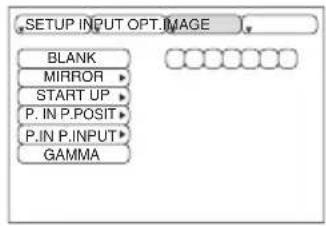
Table 6. Image Menu
| Item Description | |
| BLANK | Select Blank Screen Color: Select color with the and buttons. • The image is cleared and the entire screen is displayed in the selected color, when BLANK mode is set with BLANK ON, or when there is no signal for 5 minutes. |
| MIRROR | Select Mirror Status: Select mirror status with and buttons. |
| START UP | Setup Initial Screen Display: Select TURN ON with the button. Clear Initial Screen Display: Select TURN OFF with the button. • Note that if TURN OFF is selected the blank screen is displayed in blue when there is no signal. |
| P. IN P. POSIT | Select Position of P. in P. Display : Press the ① or ⑦ button. ■ ④← ① □ ①← ① □ ①← ① □ • P.IN P. function superimposes a video image over RGB or DVI signals. |
| P. IN P. INPUT | Select signal of P. in P. Display : Press the ① or ⑦ button. VIDEO ①← S-VIDEO ←COMPONENT |
| GAMMA | Select Gamma mode: Select the gamma mode with the ⑧ button. NORMAL ①← CINEMA ←DYNAMIC |
Options Menu
The following adjustments and settings are available when OPT. is selected on the menu. Select an item with the and buttons, and start or stop operation with the and buttons. The function indicated (^**) are effective on video input mode only, not on RGB input mode, except in the P.IN P. window on RGB input mode.
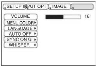
Table 7. Options Menu
| Item Description | |
| VOLUME | Volume Adjustment: Reduce VOLUME ⇔ Increase VOLUME ⇔ |
| MENUCOLOR | Select Menu Background Color: Select with the and buttons. |
| LANGUAGE | Select Menu Display Language: Select with the and buttons. |
| AUTO OFF | Set AUTO OFF: Set 1~99 minutes with the and buttons. The system automatically enters the standby mode when a signal is not received for the set time.Clear AUTO OFF: Select STOP (0 min.) with the button. When STOP is selected the system does not enter the standby mode even if no signal is received. |
| SYNC ON G | SYNC ON G Valid: Select TURN ON with the button.SYNC ON G Invalid: Select TURN OFF with the button.• May not be displayed correctly with some input signals when SYNC ON G is valid. In such cases, remove the signal connector so that no signal is received, set SYNC ON G to invalid, and reconnect the signal. |
| WHISPER | Set / Crear WHISPER Mode: Press the and button.When the WHISPER is selected, the WHISPER mode is active. In the WHISPER mode, acoustic moise level from the unit is reduced, and brightness level on screen is a little lower. |
No Signal Menu
The same adjustments and settings are available with the Image and Options menus when the MENU button is pressed during display of the "NO INPUT IS DETECTED ON " or "SYNC IS OUT OF RANGE ON " message while no signal is received.
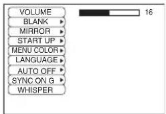
Table 8. No Signal Menu
| Item Description | |
| VOLUME | Volume Adjustment: Reduce VOLUME ⇔ Increase VOLUME ⇔When this function is used, audio input is automatically switched to video. The audio input can be switched by moving the DISK PAD left and right during the display of the volume adjustment bar. The volume adjustment bar is displayed by pressing VOLUME ⇔ VOLUME button. |
| BLANK | Select Blank Screen Color: Select the color with the and buttons.The image is cleared and the entire screen is displayed in the selected color, when BLANK mode is set with BLANK ON, or when there is no signal for 5 minutes. |
| MIRROR | Operation Start/Stop: Press the ⊙ button.Select Mirror Status: Select the mirror status with the and buttons. |
| START UP | Operation Start/Stop: Press the ⊙ button.Setup Initial Screen Display: Select the TURN ON with the button.Clear Initial Screen Display: Select the TURN OFF with the ⊙ button.Note that if TURN OFF is selected the blank screen is displayed in blue when there is no signal. |
| MENU COLOR | Select Menu Background Color: Select the color with the and buttons. |
| LANGUAGE | Operation Start/Stop: Press the ⊙ button.Select Menu Display Language: Select the language with the and buttons. |
| AUTO OFF | Operation start/stop: Press the ⊙ button.Set AUTO OFF: Set 1~99 minutes with the and buttons. The system automatically enters the standby mode when a signal is not received for the set time.Clear AUTO OFF: Select the STOP (0 min.) with the button. When the STOP is selected the system does not enter the standby mode even if no signal is received. |
| SYNC ON G | Operation Start/Stop: Press the ⊙ button.SYNC ON G Valid: Select the TURN ON with the button.SYNC ON G Invalid: Select the TURN OFF with the button.• May not be displayed correctly with some input signals when the SYNC ON G is valid. In such cases, remove the signal connector so that no signal is received, set the SYNC ON G to invalid, and reconnect the signal. |
| WHISPER | Operation Start/Stop: Press the ⊙ button.Set / Creak WHISPER Mode: Press the and button.When the WHISPER is selected, the WHISPER mode is active. In the WHISPER mode, acoustic moise level from the unit is reduced, and brightness level on screen is a little lower. |
Lamp


HIGH VOLTAGE HIGH TEMPERATURE HIGH PRESSURE
Contact your dealer before replacing the lamp.
For the optional lamp, see the item "Optional Parts" of the Table 12.
Before replacing the lamp, switch power OFF, remove the power cord from the power outlet, and wait approximately 45 minutes until the lamp has cooled. The lamp may explode if handled at high temperatures.

WARNING A mercury lamp used in this LCD projector is made of glass and has high internal pressure. The mercury lamp can burst with a big noise due to deterioration
resulting from a shock, crack and passage of time, and can end its service life in unlit condition. Lamps also have a considerably different service life and can sometimes end up in burst or turn to unlit condition soon after use. Furthermore, when the lamp is blown up, glass fragments can get scattered around the lamp house and some gas containing mercury inside the lamp can leak out of the projector's air vent.
-
Handle the lamp with utmost care as it can burst during use if subjected to a shock or impact or if scratched or cracked.
-
Probability for the burst will increase if the lamp is used for extended period of time or used exceeding the period of replacement. You are advised to follow instructions for lamp replacement as soon as they are given (Refer to Table 9 of Page 20, Table 10 of Page 21). Avoid any reuse of an old lamp (used lamp) since such reuse can result in burst.
-
In case the lamp gets blown up in a short period of time after use, some electrical failures or troubles other than the lamp itself may be suspected as causes. Under such circumstances, consult the store where you purchased it or a service company.
-
Should the lamp burst (accompanied by a big bursting noise), perform ventilation sufficiently, and exercise maximum caution not to inhale any gas out of the projector's air vent or not to let it enter your eyes or mouth.
-
Should the lamp burst (accompanied by a big bursting noise), make absolutely sure to unplug the power cord from the outlet and ask the store where you bought the lamp for immediate replacement. You should not engage in cleanup or replacement of the lamp by yourself since scattered glass fragments can damage the inside of projector or can result in personal injury when you handle it.
-
When you dispose of any used lamps, be sure to observe and follow local ordinances and regulations of the area or district where they are subjected to disposal. Generally speaking, the lamps are treated similarly as glasses and bottles in most cases, but there are areas or districts where lamps are classified as a separate collection, and so be sure to use caution.
-
Never use the lamp in a state where the lamp cover is removed.
Lamp Life
Projectile lamps have a finite life. The image will become darker, and hues will become weaker, after a lamp has been used for a long period of time.
Replace the lamp if the LAMP indicator is red, or the CHANGE THE LAMP message appears when the projector is switched ON. See Table 9 of P.20 and Table 10 of P.21.
NOTE - The LAMP indicator is also red when the lamp unit reaches high temperature. Before replacing the lamp, switch power OFF, wait approximately 20 minutes, and switch power ON again. If the LAMP indicator is still red, replace the lamp.
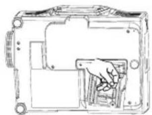
Replacing the Lamp
- Switch the projector OFF, remove the power cord from the power outlet, and wait at least 45 minutes for the unit to cool.
- Prepare a new lamp.
- Check that the projector has cooled sufficiently, and gently turn it upside down.
- Loosen the two screws as shown in the diagram, and remove the lamp cover.
- Loosen the two screws, and gently remove the lamp while holding the grips. Touching the inside of the lamp case may result in uneven coloring.
- Install the new lamp and tighten the two screws firmly. Also steadily push the opposite side of the screwed lamp into the unit.
- Replace the lamp cover in position and tighten the screw firmly.
- Gently turn the projector right-side up.
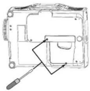
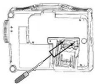

CAUTION · Ensure that screws are tightened properly. Screws not tightened fully may result in injury or accidents.
- Do not use the projector with the lamp cover removed.
Resetting the Lamp Timer
Reset the lamp timer after replacing the lamp. When the lamp has been replaced after the LAMP indicator is red, or the CHANGE THE LAMP message is displayed, complete the following operation within ten minutes of switching power ON. The power will be turned off automatically in over 10 minutes.
- Switch power ON, and press the RESET button, for approximately three seconds. The 'LAMP xxxx hr' message will appear on the lamp timer on the bottom of the screen.
- Press the MENU button on the remote control transmitter, or the RESET button on the control panel, while the lamp timer is displayed. The 'LAMP xxxx 0 ■CANCEL' message will then appear.
- Press the and select 0, and wait until the timer display is cleared.
NOTE Do not reset the lamp timer without replacing the lamp. Reset the lamp timer always when replacing the lamp. The message functions will not operate properly if the lamp timer is not reset correctly.
- An air filter is attached to the optional lamp. Replace the filter after replacing the lamp.
Air Filter
Replacing the Air Filter
Replace the air filter if contamination cannot be removed, or if it is damaged.
- Remove the filter lid.
- Pull and remove the old filter from the filter box.
- Insert the new filter to the filter box. Push left and right edges of the filter with fingers in order to fit the filter to the box properly. Check that there is no gap between the filter and plastics at top, left and right side edge of the filter.
- Set the filter lid.
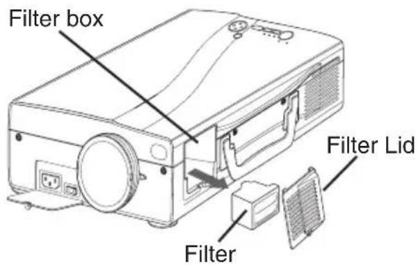
Cleaning the air Filter
The air filter should be cleaned as described below at intervals of approximately 300 hours.
- Switch the projector power supply OFF, and remove the power cord from the power outlet.
- Clean the air filter with a vacuum cleaner.

CAUTION • Switch power OFF and remove the power cord from the power outlet before beginning maintenance work. Please read the separate "SAFETY TRUCTIONS" thoroughly to ensure that maintenance is performed correctly.
- Replace the air filter if contamination cannot be removed, or if it is damaged. Contact your dealer in such case. For the optional air filter, see the item "Optional Parts" of the Table 12.
- Do not use the equipment with the air filter removed.
- When the air filter is clogged with dust etc. the power supply is switched OFF automatically to prevent the temperature rising inside the projector.
Other Maintenance
Maintenance Inside the Equipment
For safety reasons, ensure that the equipment is cleaned and checked by the dealer once every two years. Maintaining the equipment by yourself is dangerous.
Cleaning the Lens
Gently wipe the lens with lens cleaning paper. Do not touch the lens with your hands.
Cleaning the Cabinet and Remote control transmitter
Gently wipe with a soft cloth. If dirt and stains etc. are not easily removed, use a soft cloth dampened with water, or water and a neutral detergent, and wipe dry with a soft, dry cloth.

CAUTION • Switch power OFF and remove the power cord from the power outlet before beginning maintenance work. Please read the separate "SAFETY TRUCTIONS" thoroughly to ensure that maintenance is performed correctly.
- Do not use detergents or chemicals other than those noted above (e.g. benzene or thinners).
- Do not use cleaning sprays.
- Do not rub with hard materials, or tap the equipment.
NOTE - When this projector is brought into a warm room from a cold outdoor, condensation can take place on the projection lens and mirror inside, blurring the screen and reducing your eyesight, but do not worry. The condensation will disappear and the screen will return to a normal condition no sooner than the projector acclimates to the surrounding temperature.
OSD Message
The messages as described below may appear on the screen at power ON. Take the appropriate measures when such a message appears.
Table 9. OSD Message
| Message Contents | |
| CHANGE THE LAMP AFTER REPLACING LAMP, RESET THE LAMP TIME. *1) | The message shown at left appears after the lamp has been used for more than 1300 hours. The lamp is approaching the end of its life. Power is switched OFF automatically when the lamp reaches the end of its life. Prepare a new lamp for installation. Always reset the lamp timer after replacing the lamp. |
| CHANGE THE LAMP AFTER REPLACING LAMP, RESET THE LAMP TIME. THE POWER WILL TURN OFF AFTER ** hr. *1) | The lamp will reach the end of its life in ** hours. Power will be switched OFF automatically in ** hours. Replace the lamp as shown in P.17~18 “Lamp”. Always reset the lamp timer after replacing the lamp. |
| CHANGE THE LAMP AFTER REPLACING LAMP, RESET THE LAMP TIME. THE POWER WILL TURN OFF AFTER 0 hr. | The lamp has reached the end of its life. Power will be switched OFF in a few minutes. Switch power OFF immediately and replace the lamp as shown in P.17~18 “Lamp”. Always reset the lamp timer after replacing the lamp. |
| NO INPUT IS DETECTED ON *** | No input signal found. Check signal input connections and signal sources. |
| SYNC IS OUT OF RANGE ON *** | The horizontal or vertical frequency of the input signal is not within the specified range. Check the specifications of the equipment and the signal source. |
| CHECK THE AIR FLOW | The internal temperature has risen. Switch power OFF, and wait 20 minutes until the equipment cools. Check the following and Switch power ON again. * Are the ventilation openings blocked. * Is the air filter dirty. * Is the ambient temperature in excess of 35°C. |
NOTE *1) This message is cleared automatically after approximately three minutes, and appears every time power is switched ON.
Indicators Message
The POWER indicator, LAMP indicator, and TEMP indicator are lit and blank as follows. Take the appropriate measures.
Table 10. Indicators Message
| STANDBY/ON indicator | LAMP indicator | TEMP indicator | Contents |
| Lights orange | Turns off | Turns off The Standby mode has been set. | |
| Blinks green | Turns off | Turns off Warming up. Please wait. | |
| Lights green | Turns off | Turns off ON. Normal operation possible. | |
| Blinks orange | Turns off | Turns off Cooling. Please wait. | |
| Lights red | Lights red | Turns off | Lamp is not lit.The interior of the equipment may be too hot. Switch power OFF, wait 20 minutes until the equipment cools, and check whether the ventilation openings are blocked, whether the air filter is dirty, or whether the ambient temperature exceeds 35 °C. And switch power ON again. Replace the lamp if the same problem occurs. |
| Lights red | Blinks red | Turns off | Lamp or lamp cover is not found, or hasn't been fitted in correctly.Switch power OFF, and wait for 45 minutes until the equipment cools. Check fitting of the lamp and lamp cover, and switch power ON again. Contact your dealer if the same problem occurs again. |
| Lights red | Turns off | Blinks red | The cooling fan is not operating.Switch power OFF, and wait for 20 minutes until the equipment cools. Check for foreign matters in the fan, and switch power ON again. Contact your dealer if the same problem occurs again. |
NOTE *1) When the internal temperature becomes excessive power is switched OFF automatically for safety reasons, and the indicator is extinguished. Set the power switch to [O] and wait for 20 minutes until the equipment has cooled sufficiently.
Symptom
Before requesting repair, check in accordance with the following chart. If the situation cannot be corrected, then contact your dealer.
Table 11. Symptom
| Symptom Possible cause Remedy Page | ||
| The power is not turned on. | The main power switch is not turned on. | Turn on the main power switch. |
| The power cord is disconnected. | Plug the power cord into an AC power outlet. | |
| The main power was disconnected during operation by the power failure and so on. | Turn off the projector with the main power switch (set the power switch to [O]), and wait for about 20 minutes. When the equipment has cooled enough, turn power on. | |
| No video or audio. | The input is not correctly set. | Use the projector or remote control transmitter to set. |
| No signal input. Connect correctly. | ||
| Video is present but no audio. | The projector is not correctly connected. | Connect correctly. |
| The volume is set to minimum. | Press VOLUME on the remote control or display the menu screen and adjust the volume. | |
| Mute is turned on. | Press the MUTE button. | |
| Audio is present but no video. | The projector is not correctly connected. | Connect correctly. |
| The brightness adjustment knob is rotated fully clockwise. | Select BRIGHT with the MENU button and the press the button. | |
| The lens cap is still attached. Remove the lens cap. | ||
| Colors are pale and color matching is poor. | Color density and color matching are not correctly adjusted. | Adjust the video. |
| Images are dark. | Brightness and contrast are not correctly adjusted. | Adjust the video. |
| The lamp is nearing the end of its service life. | Replace with a new lamp. | |
| WHISPER mode is set. Clear WHISPER mode. | ||
| Video is blurred. | Focus or H PHASE is out of adjustment. | Adjust the focus or H PHASE. |
Table 12. Specifications
| Item Specification | |||
| Product name Liquid crystal projector | |||
| Liquid crystal panel | Panel size 2.3 cm (0.9 | type) | |
| Drive system TFT active | ve matrix | ||
| Pixels 1,397,760 pixels | (1365 horizontal x 1024 vertical) | ||
| Lens Zoom lens F=2.7 ~ 3.1 f=38 | 0 ~ 49.0 mm | ||
| Lamp 220 W UHB | |||
| Speaker 1W | |||
| Power supply AC100 ~ 120V, 4.0A | / AC220 ~ 240V, 1.8A | ||
| Power consumption 360W | |||
| Temperature range 0 ~ 35°C (Operating) | |||
| Size 250 (W) x 103 (H) x 335 (D) mm | |||
| Weight (mass) 5.6 kg | |||
| RGB signal input | RGB IN | 1 | Video: Analog 0.7Vp-p, 75Ωterminator (positive)H/V. sync.: TTL level (positive/negative)Composite sync.: TTL levelD-sub 15-pin shrink jack |
| 2 | |||
| DVI | TMDS, DC: 150~1200 mV / AC: 1.56 Vp-pTTL Level (Positive/Negative) | ||
| AUDIO IN | RGB1 | 200mVrms, 20 kΩ(max. 3.0Vp-p)Stereo mini jack | |
| DVI | |||
| RGB2 | |||
| Video signal input | VIDEO | 1.0Vp-p, 75ΩterminatorRCA jack | |
| S-VIDEO | Brightness signal: 1.0Vp-p, 75ΩterminatorColor signal: 0.286Vp-p (burst signal), 75ΩterminatorMini DIN 4-pin jack | ||
| COMPONENTVIDEO | Y 1.0 | Vp-p, 75ΩTerminator (Positive) | |
| Cb/Pb | 0.7 Vp-p, 75 Ω Terminator (Positive) | ||
| CR/PR | 0.7 Vp-p, 75 Ω Terminator (Positive) | ||
| AUDIO | L/MONO | 200mVrms, 20 kΩ(max. 3.0Vp-p)RCA jack | |
| R | |||
| Signal output | RGB OUT | Video: Analog 0.7Vp-p, 75Ωoutput impedance (positive)H/V. sync.: TTL level (positive/negative)Composite sync.: TTL levelD-sub 15-pin shrink jack | |
| AUDIO OUT | 200mVrms, output impedance 1 kΩ(max. 3.0Vp-p)Stereo mini jack | ||
| Control functions | CONTROL | D-sub 15-pin shrink plug | |
| USB | USB jack (B type) | ||
| Optional Parts | Lamp: DT00421Air Filter: MN04291* For others, consult your dealer. | ||
NOTE
- This specifications are subject to change without notice.
WARRANTY AND AFTER- SERVICE
If a problem occurs with the equipment, first refer to the P.20 "TROUBLESHOOTING" section and run through the suggested checks. If this does not resolve the problem contact your dealer or service company. They will tell you what warranty condition is applied.

- CONTENTS
- TABLES
- BEFORE USE
- Contents of package
- Part Names
- Part Names (continued)
- REMOTE CONTROL TRANSMITTER
- (Refer to P.9 "OPERATIONS")
- Loading the Batteries
- Installation of the Projector and Screen
- Angle Adjustment
- Cabling
- Power Connection
- Example of System Setup
- Plug & Play
- Power ON
- Power OFF
- WARNING · Please read this manual, and the separate "SAFETY INSTRUCTIONS" thoroughly before using the equipment. Always ensure that equipment is used safely.
- Basic Operation
- Setup Menu
- Input Menu
- Image Menu
- Options Menu
- No Signal Menu
- Lamp
- HIGH VOLTAGE HIGH TEMPERATURE HIGH PRESSURE
- Lamp Life
- Replacing the Lamp
- Resetting the Lamp Timer
- Air Filter
- Replacing the Air Filter
- Cleaning the air Filter
- Other Maintenance
- Maintenance Inside the Equipment
- Cleaning the Lens
- Cleaning the Cabinet and Remote control transmitter
- OSD Message
- Indicators Message
- Symptom
- WARRANTY AND AFTER- SERVICE
Brand : HITACHI
Model : CPSX5600W
Category : Projector