USER MANUAL GA-8TRS300M GIGABYTE
The sequence of installation may differ depending on the type of case and devices used. The installation instructions below apply to GIGABYTE's desktop systems and are for reference only.
Refer to the user's manual included for detailed motherboard specifications.
- Before installing the devices, make sure they are compliant with the connectors on your computer.
- Before installing the devices, be sure to turn off the devices and your computer. Unplug the power cord from the power outlet to prevent damage to the devices and the system components.
- Place the computer system on a stable surface to prevent improper installation resulted from shaking.

Installing a CPU and CPU Cooler
A. Installing an Intel CPU (skip this step if the motherboard has a built-in CPU)
A-1 Refer to the following instructions based on your CPU specifications:
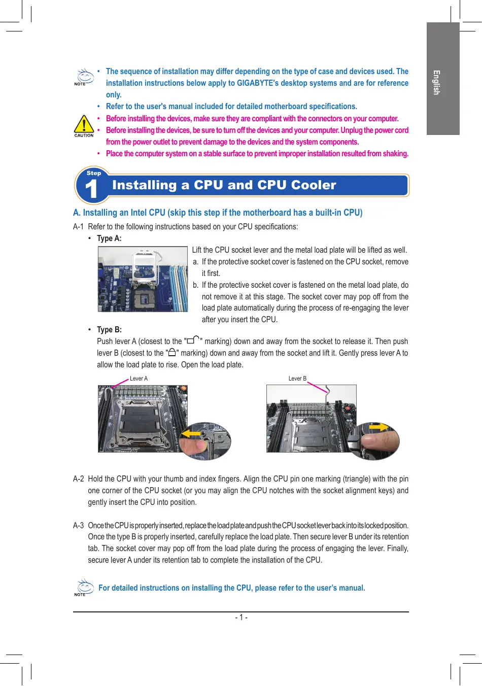
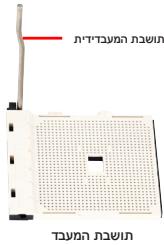
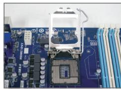
Lift the CPU socket lever and the metal load plate will be lifted as well.
a. If the protective socket cover is fastened on the CPU socket, remove it first.
b. If the protective socket cover is fastened on the metal load plate, do not remove it at this stage. The socket cover may pop off from the load plate automatically during the process of re-engaging the lever after you insert the CPU.
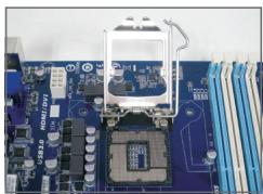
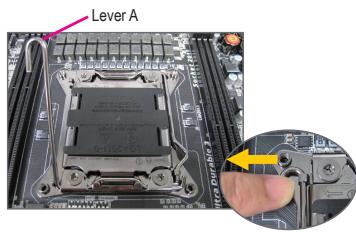
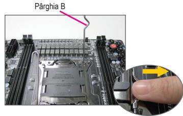
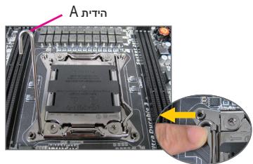
Push lever A (closest to the "□" marking) down and away from the socket to release it. Then push lever B (closest to the "□" marking) down and away from the socket and lift it. Gently press lever A to allow the load plate to rise. Open the load plate.

A-2 Hold the CPU with your thumb and index fingers. Align the CPU pin one marking (triangle) with the pin one corner of the CPU socket (or you may align the CPU notches with the socket alignment keys) and gently insert the CPU into position.
A-3 Once the CPU is properly inserted, replace the load plate and push the CPU socket lever back into its locked position. Once the type B is properly inserted, carefully replace the load plate. Then secure lever B under its retention tab. The socket cover may pop off from the load plate during the process of engaging the lever. Finally, secure lever A under its retention tab to complete the installation of the CPU.

For detailed instructions on installing the CPU, please refer to the user's manual.
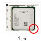
B. Installing an AMD CPU (skip this step if the motherboard has a built-in CPU)
B-1 Completely raise the CPU socket lever. Align the CPU pin one (small triangle marking) with the triangle marking on the CPU socket and gently insert the CPU into the socket. Make sure that the CPU pins fit perfectly into their holes.
B-2 Once the CPU is positioned into its socket, place one finger down on the middle of the CPU, lowering the socket lever and latching it into the fully locked position.


- Do not force the CPU into the CPU socket. The CPU cannot fit in if oriented incorrectly. Adjust the CPU orientation if this occurs.
- DO NOT touch socket contacts. To protect the CPU socket, always replace the protective socket cover when the CPU is not installed.
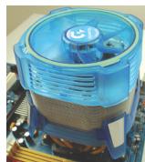
C. Installing the CPU cooler


C-1 Before installing the CPU cooler, please first add a thin layer of heat sink paste on the surface of the CPU. Then install the cooler (refer to the installation manual for your CPU cooler).
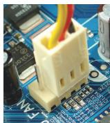
C-2 Connect the CPU cooler cable to the CPU_FAN connector located on the motherboard so that the cooler can properly function to prevent the CPU from overheating.

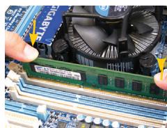
Installing Memory
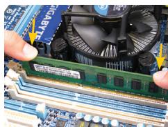
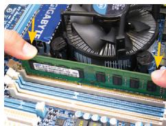
Note the orientation of the memory module. Spread the retaining clips at both ends of the memory socket. Place the memory module on the socket. As indicated in the picture on the left, place your fingers on the top edge of the memory, push down on the memory and insert it vertically into the memory socket. The clips at both ends of the socket will snap into place when the memory module is securely inserted.

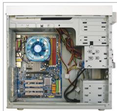
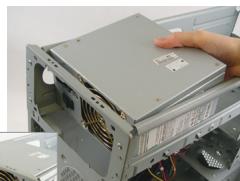
Preparing the Case and Installing a Power Supply
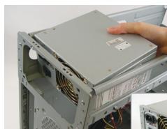
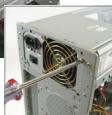
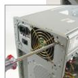
Using the GIGABYTE desktop system as the demonstration example, please first remove both sides and the lid of the case in order to install the power supply. Place the power supply in the correct place in the case and secure it with screws. Installation and placement of the power supply may differ depending on the type of case used.

To ensure sufficient power can be supplied to your system, it is recommended that a power supply of good quality be used. If a power supply is used that does not provide the required power, the result can lead to an unstable or unbootable system.
Step
4
Installing the Motherboard
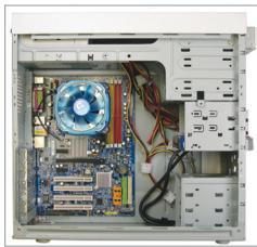
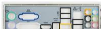
Remove the original I/O shield from the back of the case and replace it with the motherboard I/O shield. Place the motherboard within the case by positioning it into its I/O shield. Align the mounting screw holes on the motherboard with their corresponding mounting holes on the case. Secure the motherboard in place with screws.

I/O Shield
Step
5
Installing an Expansion Card
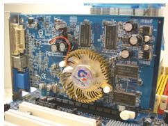
PCI Express Graphics Card
Locate an expansion slot that supports your card and remove the slot cover from the case back panel. Then insert the expansion card into the slot. Secure the expansion card's bracket to the case back panel with a screw.

- Before purchasing an expansion card, check the length of the card, making sure it can fit into your case.
- Make sure that the expansion card is fully seated in its slot.
Step
6
Installing IDE and SATA Devices

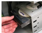
Installing an Optical Drive
6-1 Install your optical drives, such as DVD-ROM and CD-ROM drives.
Remove the 5.25" drive bay cover from the front of the case. Mount the optical drive in the 5.25" drive bay and secure it with screws.

Installing a Hard Drive
6-2 Install your IDE and SATA hard drives.
Install the hard drive into a drive bay within the case and secure it with screws.

- One motherboard IDE connector can connect up to two IDE devices. Prior to installation, check the jumper settings (master and slave) on your IDE devices.
- If more than one hard drive is installed, enter system BIOS Setup to set the hard drive boot sequence.

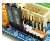
Connecting Cables to Internal Connectors
7-1 Connect cables to internal connectors and headers on the motherboard, including IDE/SATA connectors, and front panel audio, USB, IEEE 1394 headers, etc.
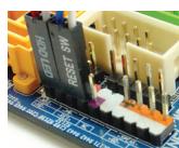
7-2 Attach the front panel module (differs depending on the case design, consisting of power indicator, hard drive activity indicator, speakers, reset switch, power switch, etc.) from the case to the front panel header (F PANEL) on the motherboard.
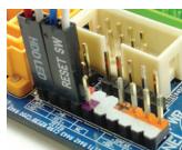
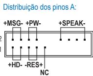
Front Panel Header
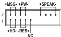
Pin Assignments A:
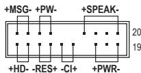
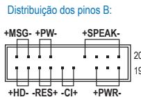
Pin Assignments B:
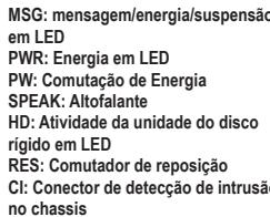
MSG: Message/Power/Sleep LED
PWR: Power LED
PW: Power Switch
SPEAK:Speaker
HD: Hard Drive Activity LED
RES: Reset Switch
Cl: Chassis Intrusion Header
(Note) The pin assignments for the front panel header may differ by model. Refer to the motherboard user's manual for the actual pin assignments.

Connecting Peripherals
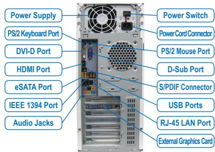
Back Panel of the Case
Once the steps above have been completed, connect the peripheral devices to the computer, such as the keyboard, mouse, monitor, etc. Then connect the power, turn on the system, and install all required software.

Conector do paine frontal
YctaHOBka CNCTeMHoN pIaTbI
CnHmnte 3aIyUkPy pa3bEmOB BBOda/BbIBOda Ha 3aIeHne HaneHn Kopnyca n yCTAHOBITE Ha ee MeTO NaHEnb pa3bEmOB BBOda/BbIBOda nKOMNIJEKTa noCTABKN CNTeMHNO nPaTbI. YCTAHOBITE CNTeMHYIO nPATEB KOPnyce, COBMecTINB pa3bEmbl Ha 3aIeHne HaneHn CNCTeMHNO nPATE C OTBepCTNAMn H aNaHEn BBOda/BbIBOda. COBMecTIne KpeENXhIE OTBepCTNcNTeMHNO nPATAc COoTBETCTByUQIMn OTBepCTNIMn Kopnyca. 3akpenite CNTeMHYIO nPATAy B Kopnyce PIK c NOMOuBvHTOB.
3aŋnyuka pa3bEmOB BBOda/BbBOda

YctaHOBka pnaTbI paCwnpeHnA
YCTAHOBKa JKeCTKOrO DnCKa
6-2 YctaHObKa JeeCTkoRo IDE-n SATA-dncka
YctaHOBtE JcK Tm DnCK BOTcEK DnIg JcKToKO rCaKCAu 3aKpeNTe ETO BHTAMN.

- OdnpaaBemIDE hacnCTeMHNOIpaTe nOndepKNaBaet dBa IDE-ycTpoiCTBa.Ipeed yctaHOBkoIIDE-ycTpoiCTB onpeJeHInTe c NOMoUIOpeMbIueK COOTBeTCTByOuIN peXIM pa60tbl (master nn slave).
- EcnBbIyctaHOBNB KOMNbIOTep HeckONbKO JcEeTKIN DnCKOB, Bbl3OBITE MeHOb HacTpoekBIOS Setup n onpeDenite JceTkn DnCK, c KOTOPORO 6ydtarpykaTbcra CnCTema.

IopKnloueHne ka6eNei K BHyTpeHHM pa3bEmaM
7-1 Подкл�чite Иntерфсьные кабели КВУтpeним pa3ьемам Ha систмов пiate: IDE/SATA, Audio
ha nepedneи paheи, USB, IEEE 1394 n.T.n.
7-2Плдкнчite 3e mentsbHa nepeDnei naHelen Koprnyca PIK (KoJIuYeCTBO n pacnIoNoXeHne 3eMeENTOB 3aBncIT OT MOeHNI Koprnyca; o6bIHO, Ha nepeDnei naHelen npCysTcByOT INdNKaTOP nITAHN, INdNKaTOP aKTHBHOCTN JKeCTKOrO DnCKA, DnHaMnK Koprnyca, KhoNkA nepe3arpy3KN i KhoNkA pNTaHn) K pa3bemy nepeDnei naHelen (F PANEL) ha cIcTeHMoi Pnate.
Pazbem nepeDnei naheIi

Pa3MeueHne KOHTAKTOB:BapnAHT A

PazmeüeHne KOHTAKTOB:Bapnait B
MSG: INHIMKATOP COo6bEmnHa/ PINTAHNOJXOHNDAH
PWR: INDnkaTop nntaHn
PW: Khonka BkHouenn nTuHa
RES: Khoonka nepe3aqrty3kn
Cl:ДатчИВСКРБITЯКОр顺序CA
(Приимechаиме) PaCNoIOnOKeHnE KOHTaKToB pa3bema nepeDnei paHei nIpa3JIuNbIX MoTeNeI pIaTMOKET pa3NIuATbc. Ha3NaueHnE KOHTaKToB pa3bema F_PANEL npIBeDEHO B PykoBOdCTBe IIOJIb3OBaTErnaCtEMHOI pIaTbI.

PoiKlIouHne nepuΦepnHbIX ycTpoiCTB
PacnoJoxeHne pa3bemOB Ha 3aDnei naHei
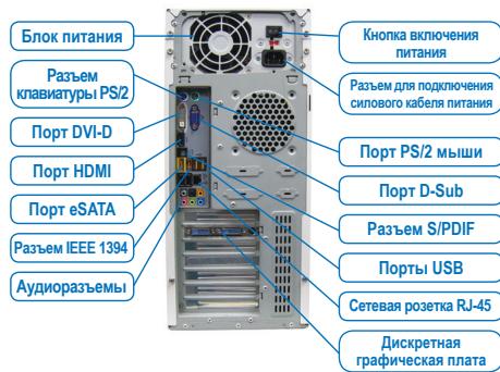
BbIOnHnB Bce nepeuucnEHHbIe DeIcTBnI, nOKnIOUHTe K KOMNbIoTepy nepnIepnHbIe yCTPOICTBa:KnabNAtypy,MbIb,MOHITOp nT.I. POnKIOUHTe BInkY CInOBOro Ka6eJIa B cTeByIO po3ETky,BKNIOHTe PI N uYctAHOBtte Heo6xOdImoe nporpamMHOe oecneueHne.

Adum Bellegin Kurulumu
Push lever A (closest to the "□" marking) down and away from the socket to release it. Then push lever B (closest to the "□" marking) down and away from the socket and lift it. Gently press lever A to allow the load plate to rise. Open the load plate.

PWR: LED pornography
PW: Intrerupator de alimentare
SPEAK: Difuzor
HD:LED activate hard disk
RES: Intrerupator de reinitializare
(wnnnn nn nnnn nn nnnn nn nnnn nn nnnn nn nnnn nn
TAYAN WNN'ON 19 NNN. TAYAN NNN INN NNN PINK ON 1-2
OON, TAYAN NNN BY IIONN WNN INN INN (IINW NNN)
PNNN TAYAN WNN INN INN INN
0000000000000000
n, Twn nn nnn nn nn nn nn nn nn nn nn nn nn nn nn nn nn nn nn nn nn nn nn nn nn nn nn nn nn nn nn nn nn nn nn nn nn nn nn nn nn nn nn nn nn nn nn nn nn nn nn nn nn nn nn nn nn nn nn nn nn nn nn nn nn nn nn nn nn nn nn nn nn nn nn nn nn nn nn nn nn nn nn nn nn nn nn nn nn nn nn nn nn nn nn nn nn nn nn nn nn nn nn
nnp nnp npnnn nn nnnnnnnnnnnnnnnnnnnnnnnnnnnnnnnnnnnnnnnnn
.

n nn nnnnnnnnnnnnnnnnnnnnnnnnnnnnnnnnnnnnnnnnnnnnnnnnnnnnnnnnnnnnnnnnnnnnnnnnnnnnnnnnnnnnnnnnnnnnnnnnn
Taynn npn .
y nnnn nn nnnn nn nnn nnnn nnnn nnnn nnnn nnnn nnnn nnnn nnnn nnnn nnnn nnnn nnnn nnnn nnnn nnnn nnnn nnnn nnnn nnnn nnnn nnnn nnnn nnnn nnnn nnnn nnnn nnnn nnnn nnnn nnnn nnnn nnnn nnnn nnnn nn
Pnnpnnn nnnn nnnn nn nnnn nnnn nnnn nnnn nnnn nnnn nnnn nnnn nnnn nnnn nnnn nnnn nnnn nnnn nnnn nnnn nnnn nnnn nnnn nnnn nnnn nnnn nnnn nnnn nnnn nnnn nnnn nnnn nnnn nnnn nnnn nnnn nnnn nnnn
1-

n nn nnnnnnnnnnnnnnnnnnnnnnnnnnnnnnnnnnnnnnnnnnnnnnnnnnnnnnnnnnnnnnnnnnnnnnnnnnnnnnnnnnnnnnnnnnnnnnnnnnnnnnnnnnnnnnnnnnnnnnnnnnnnnnnnnnnnnnnnnnnnnnnn nn
nD 790 nnnn nn
3
n nn nnnnnnnnnnnnnnnnnnnnnnnnnnnnnnnnnnnnnnnnnnnnnnnnnnnnnnnnnnnnnnnnnnnnnnnnnnnnnnnnnnnnnnnnnnnnnnnnnnnnnnnnnnnnnnnnnnn
nnnnnnnnnnnnnnnnnnnnnnnnnnnnnnnnnnnnnnnnnnnnnnnnnnnnnnnnnnnnnnnnnnnnnnnnnnnnnnnnnnnnnnnnnnnnnnnnnnnnnnnnnnnnnnnnnnnnnnnnnnnnnnnnnnnnnnnnnnnnnnn

nni nnnn nn nnnn nnnn nnnn nnnn nnnn nnnn nnnn nnnn
.
.
wannnnn nn nnnn nn nnnnnnnnnnnnnnn
n nn nnnnnnnnnnnnnnnnnnnnnnnnnnnnnnnnnnnnnnnnnnnnnnn
nynnnnnnn
n nnnnnnnnnnnnnnnnnnnnnnnnnnnnn

NOTE

Taynn TAYNN

(nnnn nn nnnnnnnnnnnnnnnnnnnnnnnnnnnnnnnnnnnnnnnnnnnnnnnnnnnnnnnnnnnnnnnnnnnnnnnnnnnnnnnnnnnnnnnnnnnnnnnnn
1
:A10
n nn nnnnnnnnnnnnnnnnnnnnn
ninn nixon,ynnn nwni pnn nnwnny a.
wnn nn nnnn nn nnnn nn nn nn nn nn nn nn nn nn nn nn nn nn nn nn nn nn nn nn nn nn nn nn nn nn nn nn nn nn nn nn nn nn nn nn nn nn nn nn nn nn nn nn nn nn nn nn nn nn nn nn nn nn nn nn nn nn nn nn nn nn nn nn nn nn nn nn nn nn nn nn nn nn nn nn nn nn nn nn nn nn nn nn nn nn nn nn nn nn nn nn nn nn nn nn
ywn nn nnnn nn nnnn nn nnnn nn nn nn nn nn
TNNNOONN
:Bao
Bn nnnn nn nnnnnnnnnnnnnnnnnnnnnnnnnnnnnnnnnnnnnnnnnnnnnnnnnnnnnnnnnnnnnnnnnnnnnnnnnnnnnnnnnnnnnnnnnnnnnnnnnnnnnnnnnnnnnnnnnnnnnnnnn
yipn nnh nx nn9.naiipnn nyipn

n nn nnnnnnnnnnnnnnnnnnnnnnnnnnnnnnnnnnnnnnnnnnnnnnnnnnnnnnnnnnnnnnnnnnnnnnnnnnnnnnnnnnnnnnnnnnnnnnnnnnnnnnnnnnnnnnnnnnnnnnnnnnnnnnnnnnnnnnnnnnnnn
B 1000000000000000000000000000000000000000000000000000000
.ynnnn
wnnnn nn nnnnnnnnnnnnnnnnnnnnnnnnnnnnnnnnnnnnnnnnnnnnnnnnnnnnnnnnnnnnnnnnnnnnnnnnnnnnnnnnnnnnnnnnnnnnnnnnnnnnnnnnn