
X79MA-GD45 - Motherboard MSI - Free user manual and instructions
Find the device manual for free X79MA-GD45 MSI in PDF.
| Product Type | Motherboard |
| Brand | MSI |
| Model | X79MA-GD45 |
| Socket | LGA2011 |
| Chipset | Intel X79 |
| Supported Memory | DDR3, 4 slots, up to 64 GB, Quad Channel |
| Memory Frequencies | DDR3 2400 (OC) / 2133 (OC) / 1800 (OC) / 1600 / 1333 / 1066 MHz |
| Audio | Realtek ALC892, 8-channel HD |
| Network | Realtek RTL8111E, Gigabit Ethernet 10/100/1000 |
| SATA Connectors | 2x SATA 6 Gb/s (SATA1~2), 4x SATA 3 Gb/s (SATA3~6) |
| RAID | RAID 0/1/5/10 (Intel Rapid Storage) |
| USB 3.0 | 2 rear ports + 1 internal connector (NEC D720200) |
| USB 2.0 | 6 rear ports + 2 internal connectors |
| Expansion Slots | 2x PCIe 3.0 x16, 2x PCIe 2.0 x1 |
| Multi-GPU | AMD CrossFireX and NVIDIA SLI |
| Dimensions | 24.4 cm × 24.4 cm (ATX form factor) |
| Power | ATX 24-pin connector (JPWR1) + ATX 8-pin connector (JPWR2) |
| BIOS | Click BIOS II with graphical interface |
| Overclocking | OC Genie for simplified overclocking, advanced manual settings |
| Internal Connectors | USB 2.0/3.0, serial port, TPM, front audio, chassis intrusion detection, Voice Genie (optional), MultiConnect (optional) |
| Security | Overheating protection, electrostatic discharge, CMOS clear jumper |
| Maintenance | Clean with a soft dry cloth. Do not use solvents. |
| Spare parts and repairability | Motherboard not user-repairable. Contact MSI support. |
| Warranty | Check the MSI website or retailer for warranty conditions. |
Frequently Asked Questions - X79MA-GD45 MSI
User questions about X79MA-GD45 MSI
0 question about this device. Answer the ones you know or ask your own.
Ask a new question about this device
Download the instructions for your Motherboard in PDF format for free! Find your manual X79MA-GD45 - MSI and take your electronic device back in hand. On this page are published all the documents necessary for the use of your device. X79MA-GD45 by MSI.
USER MANUAL X79MA-GD45 MSI
The material in this document is the intellectual property of MICRO-STAR INTERNATIONAL. We take every care in the preparation of this document, but no guarantee is given as to the correctness of its contents. Our products are under continual improvement and we reserve the right to make changes without notice.
Trademarks
All trademarks in this manual are properties of their respective owners.
MSI® is registered trademark of Micro-Star Int'l Co., Ltd.
NVIDIA® is registered trademark of NVIDIA Corporation.
ATI® is registered trademark of AMD Corporation.
AMD® is registered trademarks of AMD Corporation.
Intel® is registered trademarks of Intel Corporation.
Windows® is registered trademarks of Microsoft Corporation.
AMI is registered trademark of American Megatrends Inc.
Award® is a registered trademark of Phoenix Technologies Ltd.
Sound Blaster® is registered trademark of Creative Technology Ltd.
Realtek® is registered trademark of Realtek Semiconductor Corporation.
- JMicron® is registered trademark of JMicron Technology Corporation.
Netware® is registered trademark of Novell, Inc.
Lucid® is trademark of LucidLogix Technologies, Ltd.
VIA® is registered trademark of VIA Technologies, Inc.
■ ASMedia® is registered trademark of ASMedia Technology Inc.
iPad, iPhone, and iPod are trademarks of Apple Inc.
Revision History
| Revision | Revision History | Date |
| V1.0 | First release | 2011/10 |
Technical Support
If a problem arises with your system and no solution can be obtained from the user's manual, please contact your place of purchase or local distributor. Alternatively, please try the following help resources for further guidance.
Visit the MSI website for technical guide, BIOS updates, driver updates, and other information: http://www.msi.com/service/download
Contact our technical staff at: http://support.msi.com
Safety Instructions
Always read the safety instructions carefully.
- Keep this User's Manual for future reference.
- Keep this equipment away from humidity.
Lay this equipment on a reliable flat surface before setting it up.
- The openings on the enclosure are for air convection hence protects the equipment from overheating. DO NOT COVER THE OPENINGS.
- Make sure the voltage of the power source is at 110/220V before connecting the equipment to the power inlet.
- Place the power cord such a way that people can not step on it. Do not place anything over the power cord.
Always Unplug the Power Cord before inserting any add-on card or module.
All cautions and warnings on the equipment should be noted.
- Never pour any liquid into the opening that can cause damage or cause electrical shock.
If any of the following situations arises, get the equipment checked by service personnel:
The power cord or plug is damaged.
Liquid has penetrated into the equipment.
The equipment has been exposed to moisture.
The equipment does not work well or you can not get it work according to User's Manual.
The equipment has been dropped and damaged.
The equipment has obvious sign of breakage.
DO NOT LEAVE THIS EQUIPMENT IN AN ENVIRONMENT ABOVE 60^ (140^) IT MAY DAMAGE THE EQUIPMENT.
FCC-B Radio Frequency Interference Statement
This equipment has been tested and found to comply with the limits for a Class B digital device, pursuant to Part 15 of the FCC Rules. These limits are designed to provide reasonable protection against harmful inter

ference in a residential installation. This equipment generates, uses and can radiate radio frequency energy and, if not installed and used in accordance with the instructions, may cause harmful interference to radio communications. However, there is no guarantee that interference will not occur in a particular installation. If this equipment does cause harmful interference to radio or television reception, which can be determined by turning the equipment off and on, the user is encouraged to try to correct the interference by one or more of the measures listed below.
Reorient or relocate the receiving antenna.
- Increase the separation between the equipment and receiver.
- Connect the equipment into an outlet on a circuit different from that to which the receiver is connected.
Consult the dealer or an experienced radio/television technician for help.
Notice 1
The changes or modifications not expressly approved by the party responsible for compliance could void the user's authority to operate the equipment.
Notice 2
Shielded interface cables and A.C. power cord, if any, must be used in order to comply with the emission limits.
VOIR LA NOTICE D'INSTALLATION AVANT DE RACCORDER AU RESEAU.

Micro-Star International
MS-7738
This device complies with Part 15 of the FCC Rules. Operation is subject to the following two conditions:
1) this device may not cause harmful interference, and
2) this device must accept any interference received, including interference that may cause undesired operation.
Battery Information

European Union:
Batteries, battery packs, and accumulators should not be disposed of as unsorted household waste. Please use the public collection system to return, recycle, or treat them in compliance with the local regulations.

Taiwan:
For better environmental protection, waste batteries should be collected separately for recycling or special disposal.
廢電池請回收
California, USA:
The button cell battery may contain perchlorate material and requires special handling when recycled or disposed of in California.
For further information please visit:
http://www.dtsc.ca.gov/hazardouswaste/perchlorate/
CAUTION: There is a risk of explosion, if battery is incorrectly replaced.
Replace only with the same or equivalent type recommended by the manufacturer.
Chemical Substances Information
In compliance with chemical substances regulations, such as the EU REACH Regulation (Regulation EC No. 1907/2006 of the European Parliament and the Council), MSI provides the information of chemical substances in products at:
http://www.msi.com/html/popup/csr/evmptrtt_pcm.html
BSMI EMI 聲明
警告使用者:
WEEE (Waste Electrical and Electronic Equipment) Statement
ENGLISH
To protect the global environment and as an environmentalist, MSI must remind you that...
Under the European Union ("EU") Directive on Waste Electrical and Electronic Equipment, Directive 2002/96/EC, which takes effect on August 13, 2005, products of "electrical and electronic equipment" cannot be discarded as municipal wastes anymore, and manufacturers of covered electronic equipment
will be obligated to take back such products at the end of their useful life. MSI will comply with the product take back requirements at the end of life of MSI-branded products that are sold into the EU. You can return these products to local collection points.

DEUTSCH
Mainboard Specifications
Processor Support
- 2nd Generation Intel® Core™ i7 Processors in an LGA 2011 socket (For the latest information about CPU, please visit http://www.msi.com/service/cpu-support)
Chipset
Intel®X79 chipset
Memory Support
4x DDR3 DIMMs support DDR3 2400(OC)/ 2133(OC)/ 1800(OC)/ 1600/ 1333/ 1066 DRAM (64GB Max)
Supports Quad-Channel mode, one DIMM per channel (OC = OverClocking, for more information on compatible components, please visit http://www.msi.com/service/test-report)
LAN
Supports LAN 10/100/1000 Fast Ethernet by Realtek® RTL8111E
Audio
Integrated HD audio codec by Realtek® ALC892
8-channel audio with jack sensing
SATA
2x SATA 6Gb/s ports (SATA1~2) by Intel® X79
4x SATA 3Gb/s ports (SATA3~6) by Intel® X79
RAID
SATA1~6 support Intel® Rapid Storage Technology enterprise (AHCI/ RAID 0/ 1/ 5/ 10) by Intel® X79
USB 3.0
2x USB 3.0 rear IO ports by NEC D720200
1x USB 3.0 onboard connector by NEC D720200
Multi-GPU
Supports ATI CrossFireX™ Technology
Supports NVIDIA® SLITM Technology
Connectors & Buttons
Back panel
- 1x PS/2 keyboard/ mouse port
- 1x Clear CMOS button
- 1x Coaxial S/PDIF-out port
- 1x Optical S/PDIF-out port
- 6x USB 2.0 ports
- 2x USB 3.0 ports
- 1x LAN port
- 6x audio ports
On-Board
- 2x USB 2.0 connectors
- 1x USB 3.0 connector
- 1x Serial port connector
- 1x TPM Module connector
- 1x Front Panel Audio connector
- 1x Chassis Intrusion connector
- 1x Voice Genie connector (optional)
- 1x MultiConnect Panel connector (optional)
- 9x V-Check Points
Slots
2x PCIe 3.0 x16 slots
2x PCIe 2.0 x1 slots
Form Factor
ATX (24.4cm× 24.4cm)
Mounting Screw Holes
8x mounting holes
If you need to purchase accessories and request the part numbers, you could search the product web page and find details on our web address below http://www.msi.com/index.php
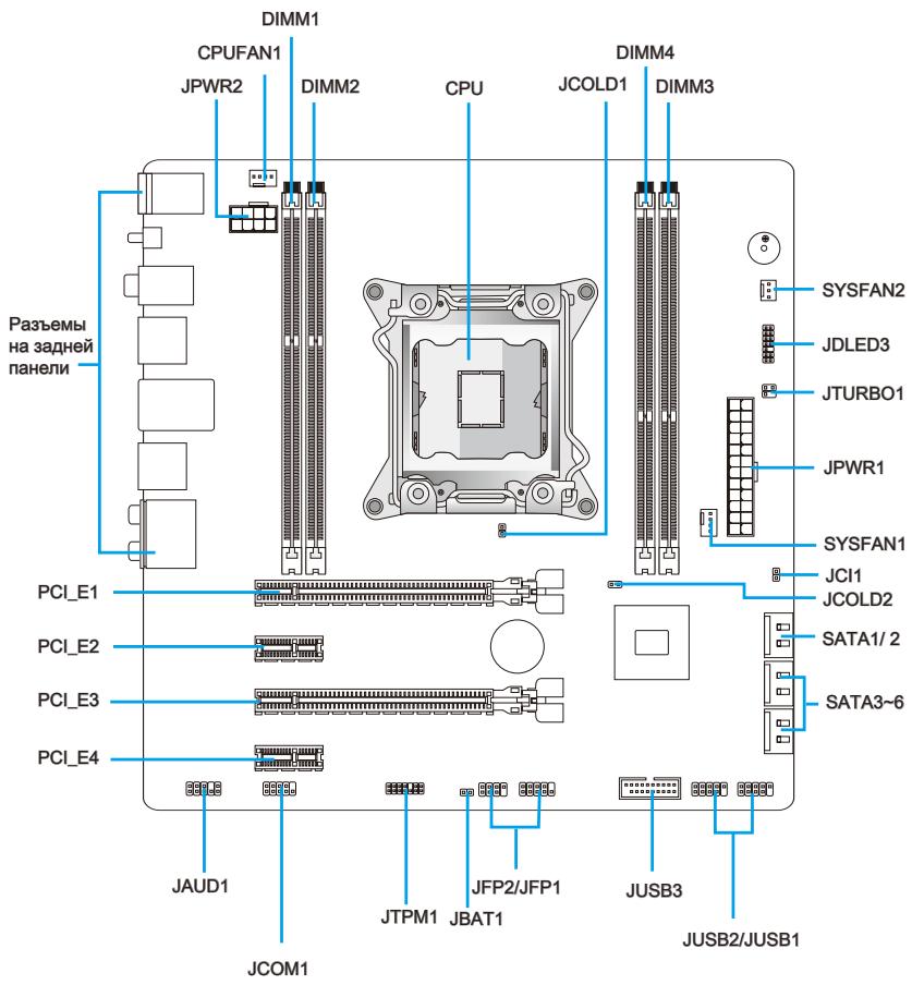
Connectors Quick Guide
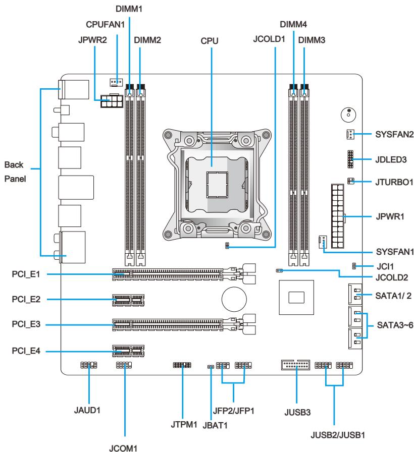
Connectors Reference Guide
| Port Type | Port Name | Page |
| LGA2011 CPU Socket | CPU | En-8 |
| ATX 24-pin Power Connector | JPWR1 | En-13 |
| ATX 8-pin Power Connector | JPWR2 | En-13 |
| DDR3 Memory Slots | DIMM1~4 | En-14 |
| PCIe x16 Expansion Slots | PCI_E1, 3 | En-16 |
| PCIe x1 Expansion Slots | PCI_E2, 4 | En-16 |
| SATA 6Gb/s Connectors | SATA1~2 | En-17 |
| SATA 3Gb/s Connectors | SATA3~6 | En-17 |
| CPU Fan Connector | CPUFAN1 | En-18 |
| System Fan Connectors | SYSFAN1~2 | En-18 |
| Front Panel Connectors | JFP1, JFP2 | En-19 |
| Front Panel Audio Connector | JAUD1 | En-19 |
| USB 2.0 Expansion Connectors | JUSB1/ JUSB2 | En-20 |
| USB 3.0 Expansion Connector | JUSB3 | En-21 |
| Chassis Intrusion Connector | JCI1 | En-21 |
| TPM Module connector | JTPM1 | En-22 |
| Serial Port Connector | JCOM1 | En-22 |
| Voice Genie Connector | JDLED3 | En-23 |
| MultiConnect Panel Connector | JTURBO1 | En-23 |
| Clear CMOS Jumper | JBAT1 | En-25 |
| Low Temperature Booting Jumper | JCOLD1, JCOLD2 | En-25 |
Back Panel Quick Guide
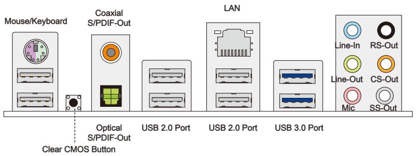
Mouse/Keyboard
A combination PS/2 mouse/keyboard DIN connector for a PS/2 mouse/keyboard.
Clear CMOS Button
There is CMOS RAM present on board that is powered by an external battery to store system configuration data. Using CMOS RAM, the system can automatically boot into the operating system (OS) every time it is turned on. If you wish to clear the system configuration, press the button to clear the data.
Coaxial S/PDIF-Out
This S/PDIF (Sony & Philips Digital Interconnect Format) connector is provided for digital audio transmission to external speakers through an coaxial cable.
Optical S/PDIF-Out
This S/PDIF (Sony & Philips Digital Interconnect Format) connector is provided for digital audio transmission to external speakers through an optical fiber cable.
USB 2.0 Port
The USB 2.0 port is for attaching USB 2.0 devices such as keyboard, mouse, or other USB 2.0-compatible devices.
USB 3.0 Port
USB 3.0 port is backward-compatible with USB 2.0 devices. It supports data transfer rate up to 5 Gbit/s (SuperSpeed).
Important
In order to use USB 3.0 devices, you must connect to a USB 3.0 port. If a USB cable is used, it must be USB 3.0 compliant.
LAN
The standard RJ-45 LAN jack is for connecting to a Local Area Network (LAN).

| LED | Color | LED State | Condition |
| Left | Yellow | Off | LAN link is not established. |
| On(Steady) | LAN link is established. | ||
| On(FLASHING) | The computer is communicating with another computer on the network. | ||
| Right | Green | Off | 10 Mbits/sec data rate |
| On | 100 Mbits/sec data rate | ||
| Orange | On | 1000 Mbits/sec data rate |
Audio Ports
These connectors are used for audio devices. The color of the jack refers to the function of the connector.
Blue-Line in: Used for connecting external audio outputting devices.
- Green- Line out: Used as a connector for speakers or headphone.
Pink-Mic: Used as a connector for a microphone.
- Black-RS-Out: Rear surround sound line out in 4/5.1/7.1 channel mode.
Orange- CS-Out: Center/ subwoofer line out in 5.1/ 7.1 channel mode.
Gray-SS-Out:Side surround sound line out in 7.1 channel mode.
CPU (Central Processing Unit)
Introduction to the LGA2011 CPU
The surface of the LGA2011 CPU has four alignment keys and a yellow triangle to assist in correctly lining up the CPU for mainboard placement. The yellow triangle is the Pin 1 indicator.
Yellow triangle is the Pin 1 indicator
Alignment Key
Important
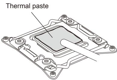
Overheating
Overheating can seriously damage the CPU and mainboard. Always make sure the cooling fans work properly to protect the CPU from overheating. Be sure to apply an even layer of thermal paste (or thermal tape) between the CPU and the heatsink to enhance heat dissipation.
Replacing the CPU
When replacing the CPU, always turn off the system's power supply and unplug the power supply's power cord to ensure the safety of the CPU.
Overclocking
This mainboard is designed to support overclocking. Before attempting to overclock, please make sure that all other system components can tolerate overclocking. Any attempt to operate beyond product specifications is not recommend. MSI does not guarantee the damages or risks caused by inadequate operation beyond product specifications.
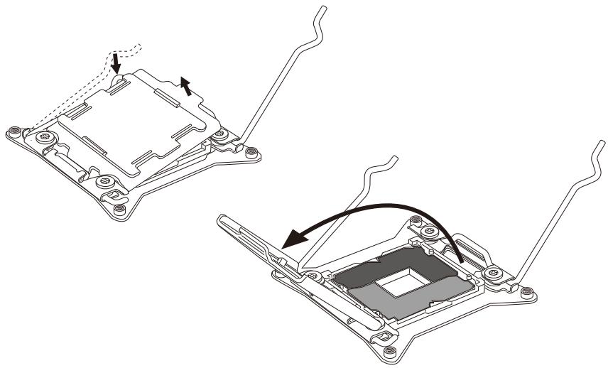
CPU & Cooler Installation
When installing a CPU, always remember to install a CPU cooler. A CPU cooler is necessary to prevent overheating and maintain system stability. Follow the steps below to ensure correct CPU and CPU cooler installation. Wrong installation can damage both the CPU and the mainboard.
- Open hinge lever. You can identify the hinge lever as below shown, it with a interlocking feature on the other end.
- Open active lever.
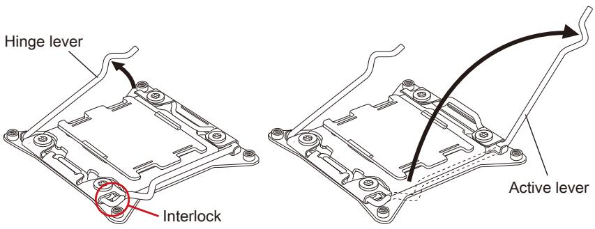
- Open the load plate by pushing down on the hinge lever
- Grasp the tab, only it has risen away from the socket, open load plate to full open position.
- Line up the CPU to fit the CPU socket. Be sure to hold the CPU by the base with the metal contacts facing downward. The alignment keys on the CPU will line up with the edges of the CPU socket to ensure a correct fit.
- Carefully close the load plate and remove the plastic protective cap.
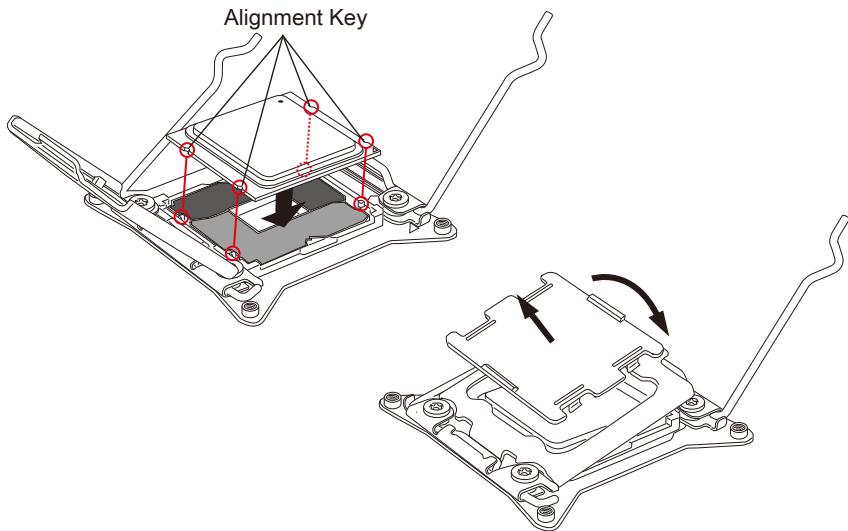
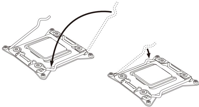
- Close the active lever with a smooth uniform motion and latch to the socket.
- Close the hinge lever with a smooth uniform motion and latch to the socket.
- Evenly spread a thin layer of thermal paste (or thermal tape) on the top of the CPU. This will help in heat dissipation and prevent CPU overheating.
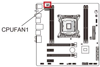
- Locate the CPU fan connector on the mainboard.
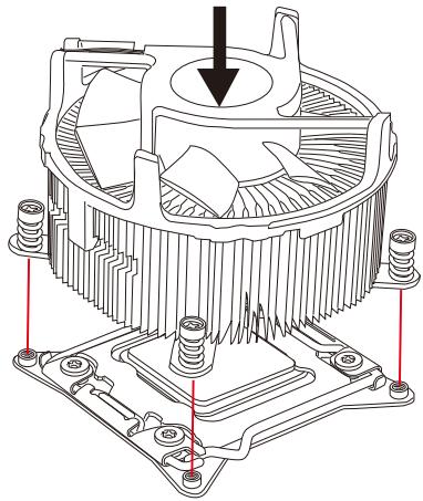
- Place the heatsink on the mainboard with the fan's wires facing towards the fan connector and the screws matching the holes on the socket.
- Using a screwdriver tighten the four captive screws (9 inch-pounds).
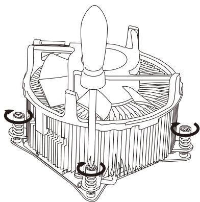
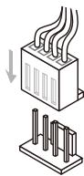
- Finally, attach the CPU fan cable to the CPU fan connector on the mainboard.
Mounting Screw Holes
When installing the mainboard, first install the necessary mounting stands required for an mainboard on the mounting plate in your computer case. If there is an I/O back plate that came with the computer case, please replace it with the I/O backplate that came with the mainboard package. The I/O backplate should snap easily into the computer case without the need for any screws. Align the mounting plate's mounting stands with the screw holes on the mainboard and secure the mainboard with the screws provided with your computer case. The locations of the screw holes on the mainboard are shown below. For more information, please refer to the manual that came with the computer case.
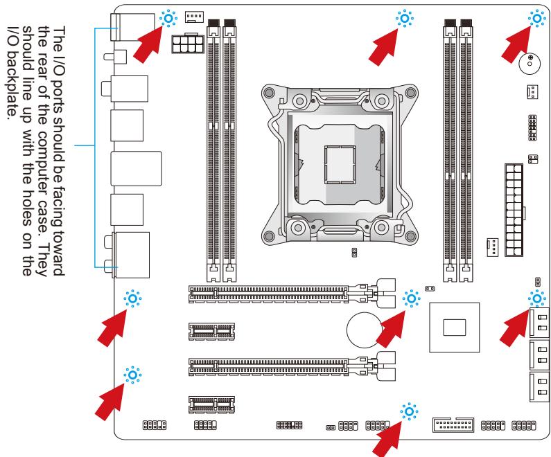
Important
- Install the mainboard on a flat surface free from unnecessary debris.
- To prevent damage to the mainboard, any contact between the mainboard circuitry and the computer case, except for the mounting stands, is prohibited.
- Please make sure there are no loose metal components on the mainboard or within the computer case that may cause a short circuit of the mainboard.
Power Supply
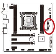
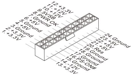
ATX 24-pin Power Connector: JPWR1
This connector allows you to connect an ATX 24-pin power supply. To connect the ATX 24-pin power supply, align the power supply cable with the connector and firmly press the cable into the connector. If done correctly, the clip on the power cable should be hooked on the mainboard's power connector.
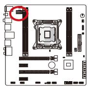
ATX 8-pin Power Connector: JPWR2
This connector provides 12V power to the CPU.
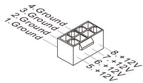
Important
Make sure that all the power cables are securely connected to a proper ATX power supply to ensure stable operation of the mainboard.
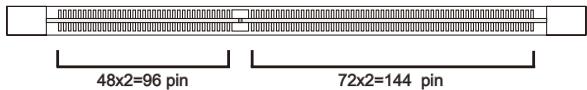
Memory
These DIMM slots are used for installing memory modules. For more information on compatible components, please visit http://www.msi.com/service/test-report
DDR3
240-pin, 1.5V
Quad Channel Memory
This mainboard supports four memory channels when you fill all four DIMM slots. Each DIMM slot provides a single channel. The memory modules can transmit and receive data with four data bus channels simultaneously to enhance system performance.
Important
- DDR3 memory modules are not interchangeable with DDR2, and the DDR3 standard is not backward compatible. Always install DDR3 memory modules in DDR3 DIMM slots.
- To ensure system stability, memory modules must be of the same type and density.
Always insert memory modules in the DIMM1 slot first. - Due to chipset resource usage, the system will only detect up to 63+ GB of memory (not full 64 GB) when all DIMM slots have 16GB memory modules installed.
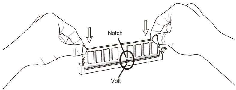
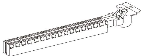
Installing Memory Modules
- Unlock the DIMM slot by pushing the mounting clip to the side. Vertically insert the memory module into the DIMM slot. The memory module has an off-center notch on the bottom that will only allow it to fit one way into the DIMM slot.
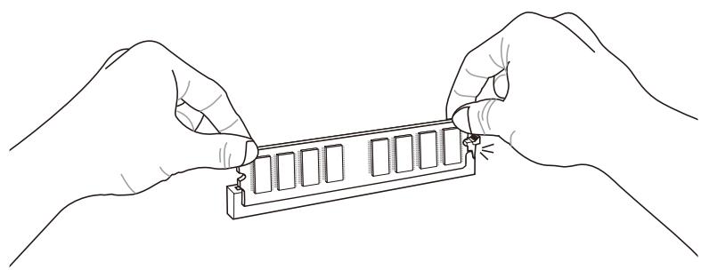
- Push the memory module deep into the DIMM slot. The plastic clip at side of the DIMM slot will automatically close when the memory module is properly seat and an audible click should be heard.
- Manually check if the memory module has been locked in place by the DIMM slot's side clip.

Expansion Slots
This mainboard contains numerous ports for expansion cards, such as discrete graphics or audio cards.
PCIe (Peripheral Component Interconnect Express) Slot
The PCIe slot supports the PCIe interface expansion card.
PCIe 3.0 x16 Slot
PCIe 2.0 x1 Slot
Important
When adding or removing expansion cards, always turn off the power supply and unplug the power supply power cable from the power outlet. Read the expansion card's documentation to check for any necessary additional hardware or software changes.
Internal Connectors
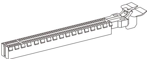
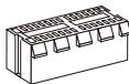
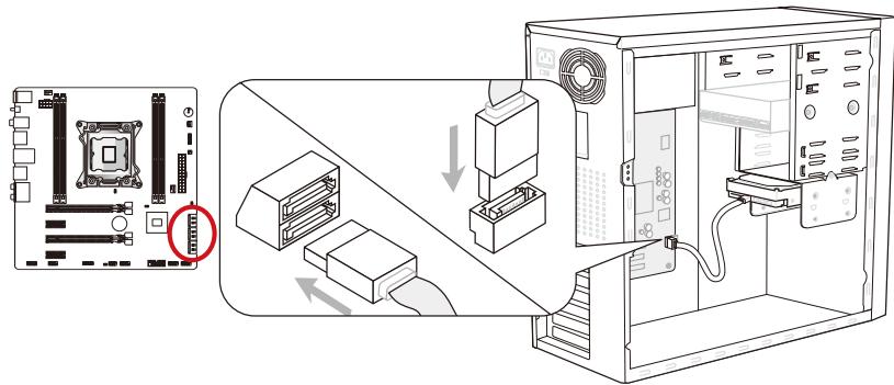
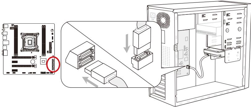
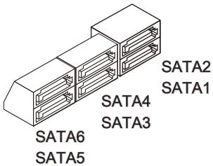
SATA Connector: SATA1~6
This connector is a high-speed SATA interface port. Each connector can connect to one SATA device. SATA devices include disk drives (HDD), solid state drives (SSD), and optical drives (CD/DVD/Blu-Ray).
* The MB layout in this figure is for reference only.
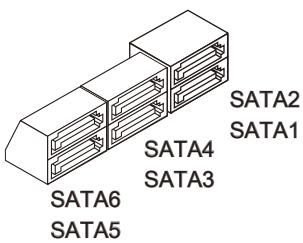
SATA1~2 (6Gb/s, by Intel® X79)
SATA3~6 (3Gb/s, by Intel® X79)
Important
- Many SATA devices also need a power cable from the power supply. Such devices include disk drives (HDD), solid state drives (SSD), and optical drives (CD / DVD / Blu-Ray). Please refer to the device's manual for further information.
- Many computer cases also require that large SATA devices, such as HDDs, SSDs, and optical drives, be screwed down into the case. Refer to the manual that came with your computer case or your SATA device for further installation instructions.
- Please do not fold the SATA cable at a 90-degree angle. Data loss may result during transmission otherwise.
- SATA cables have identical plugs on either sides of the cable. However, it is recommended that the flat connector be connected to the mainboard for space saving purposes.
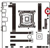
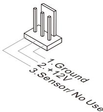
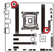
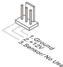
Fan Power Connectors: CPUFAN1,SYSFAN1\~2
The fan power connectors support system cooling fans with +12V . If the mainboard has a System Hardware Monitor chipset on-board, you must use a specially designed fan with a speed sensor to take advantage of the CPU fan control. Remember to connect all system fans. Some system fans may not connect to the mainboard and will instead connect to the power supply directly. A system fan can be plugged into any available system fan connector.
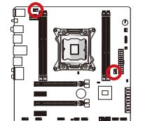
CPUFAN1/ SYSFAN1
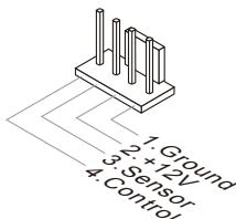
SYSFAN2
Important
- Please refer to your processor's official website or consult your vendor to find recommended CPU cooling fans.
- The CPUFAN1, SYSFAN1 connectors support Smart Fan Control with liner mode. The Control Center II utility can be installed to automatically control the fan speeds according to the CPU's and system's temperature.
- If there are not enough ports on the mainboard to connect all system fans, adapters are available to connect a fan directly to a power supply.
- Before first boot up, ensure that there are no cables impeding any fan blades.
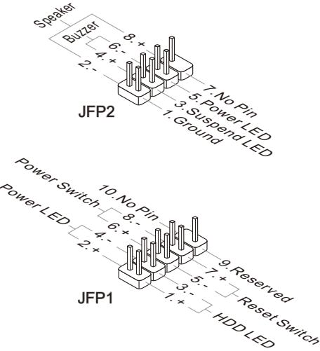
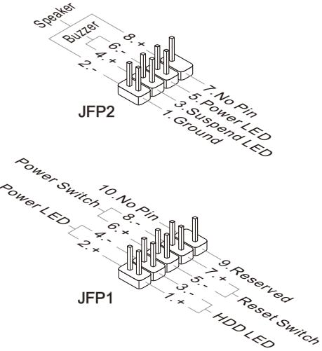
Front Panel Connectors: JFP1, JFP2
These connectors connect to the front panel switches and LEDs. The JFP1 connector is compliant with the Intel® Front Panel I/O Connectivity Design Guide. When installing the front panel connectors, please use the enclosed mConnectors to simplify installation. Plug all the wires from the computer case into the mConnectors and then plug the mConnectors into the mainboard.
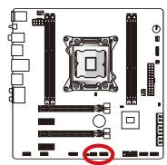
Important
- On the connectors coming from the case, pins marked by small triangles are positive wires. Please use the diagrams above and the writing on the mConnectors to determine correct connector orientation and placement.
- The majority of the computer case's front panel connectors will primarily be plugged into JFP1.
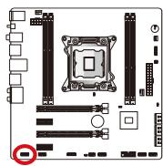
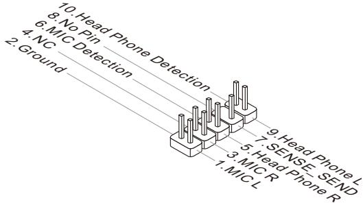
Front Panel Audio Connector: JAUD1
This connector allows you to connect the front audio panel located on your computer case. This connector is compliant with the Intel® Front Panel I/O Connectivity Design Guide.
USB 2.0 Expansion Connectors: JUSB1/ JUSB2
This connector is designed for connecting high-speed USB peripherals such as USB HDDs, digital cameras, MP3 players, printers, modems, and many others.
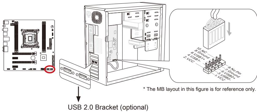
The JUSB1 (red mark) connector supports MSI's new SuperCharger technology which provides quicker USB charging of your cellular phone or other USB-powered devices. To enable this feature, please install the MSI SuperCharger application on your computer. When the SuperCharger application is turned on, the JUSB1 connector will convert data channels to extra power channels to quickly charge your connected device. Please note that when the SuperCharger application is turned on, data transmission and synchronization over the JUSB1 connector will not function. To enable the JUSB1 connector to function as a normal USB 2.0 connector, please turn off the SuperCharger application. When the computer is in stand-by or hibernation mode (S3/ S4/ S5) SuperCharger mode will automatically be enabled.
Important
- Note that the VCC and GND pins must be connected correctly to avoid possible damage.
- Please only connect one device per USB port to ensure stable charging.
- SuperCharger Technology is only available on select MSI mainboard models. Please refer to the MSI website to check if your mainboard has SuperCharger technology.
- For iPad, JUSB1 (red mark) can still charge iPad in S3, S4, S5 state.
- We recommend that don't disconnect the device when you charge it in S1 state.
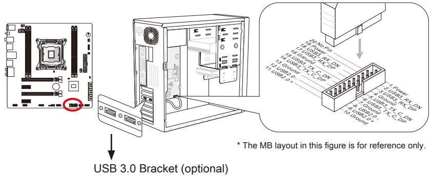
USB 3.0 Expansion Connector: JUSB3
The USB 3.0 port is backwards compatible with USB 2.0 devices. It supports data transfer rates up to 5Gbits/s (SuperSpeed).
Important
- Note that the VCC and GND pins must be connected correctly to avoid possible damage.
- To use a USB 3.0 device, you must connect the device to a USB 3.0 port through an optional USB 3.0 compliant cable.
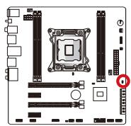
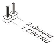
Chassis Intrusion Connector: JCI1
This connector connects to the chassis intrusion switch cable. If the computer case is opened, the chassis intrusion mechanism will be activated. The system will record this intrusion and a warning message will flash on screen. To clear the warning, you must enter the BIOS utility and clear the record.
TPM Module connector: JTPM1
This connector connects to a TPM (Trusted Platform Module). Please refer to the TPM security platform manual for more details and usages.
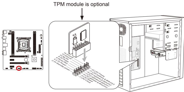
* The MB layout in this figure is for reference only.
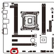
Serial Port Connector: JCOM1
This connector is a 16550A high speed communication port that sends/receives 16 bytes FIFOs. You can attach a serial device.
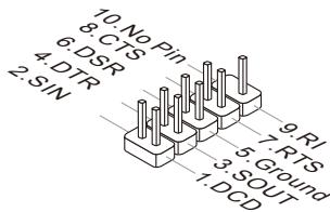
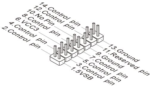
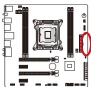
Voice Genie Connector: JDLED3 (optional)
This connector is used to link to the voice control module (optional). Please refer to its user guide for more details and usages.
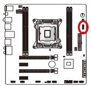
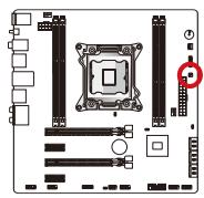
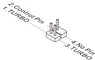
MultiConnect Panel Connector:JTURBO1 (optional)
This connector is used to connect an optional front panel for controlling the OC Genie and some additional functions. Please refer to its user guide for more details and usages.
V-Check Points
These voltage checkpoints are used to measure the current system voltages. A multimeter (not included) will be required to check voltages. To check the voltage, set the voltmeter switch to "DC", put the positive lead (red) on the positivite point of the voltage source point and the negative lead (black) on the GND (ground) point. The following table describes the voltage check points.
GND
PCH_1P5V
PCH_1P1V
CPU_PLL
DDR_C/D
DDR_A/B
CPU_SA
CPU_IO
CPU_CORE
| Point | Description |
| GND | Ground |
| PCH_1P5V | PCH 1.5 voltage. The PCH voltage is the voltage supplied to the Platform Controller Hub. |
| PCH_1P1V | PCH 1.1 voltage. Refer to PCH_1P5V. |
| CPU_PLL | CPU_PLL voltage. The PLL voltage is the voltage supplied to the process Phase Lock Loop. |
| DDR_C/D | Memory channel 2 and 3 voltage. The DDR memory voltage is the voltage supplied to the DDR memory modules on the mainboard. Lower DDR timings may require higher voltages to maintain system stability. |
| DDR_A/B | Memory channel 0 and 1 voltage. Refer to DDR_C/D. |
| CPU_SA | CPU system agent voltage (iMC). The CPU SA voltage is the voltage supplied to the IMC (Integrated Memory Controller) on the CPU. Higher overclocks may require a higher CPU SA voltage to maintain stability. |
| CPU_IO | CPU IO voltage (Uncore). The CPU IO voltage is the voltage supplied to the Uncore on the CPU. Higher overclocks may require a higher CPU IO voltage to maintain stability. |
| CPU_CORE | CPU core voltage. The CPU core voltage is the voltage supplied to the CPU core. Higher overclocks may require higher CPU core voltages to maintain stability. |
Jumpers
Clear CMOS Jumper: JBAT1
There is CMOS RAM onboard that is external powered from a battery located on the mainboard to save system configuration data. With the CMOS RAM, the system can automatically boot into the operating system (OS) every time it is turned on. If you want to clear the system configuration, set the jumpers to clear the CMOS RAM.
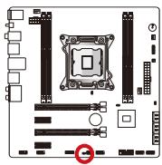

Keep Data

Clear Data
Important
You can clear the CMOS RAM by shorting this jumper while the system is off. Afterwards, open the jumper. Do not clear the CMOS RAM while the system is on because it will damage the mainboard.
Low Temperature Booting Jumper: JCOLD1, JCOLD2
These jumpers are used for liquid nitrogen cooling system to boot at an extreme low temperature. Try to set one or both jumpers to Enabled to increase the boot success rate.
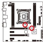

Disabled

Enabled
Important
Users will try extreme low temperature overclocking at their own risks. The overclocking results will vary according to the CPU version.
LED Status Indicators
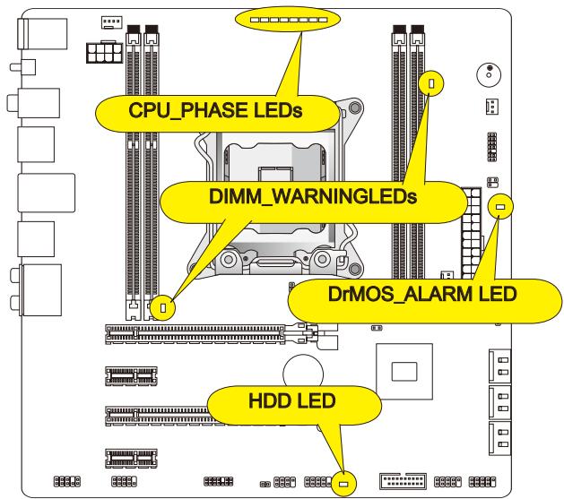
CPU_PHASE LEDs
These LEDs will change according to CPU loading. The higher the power phase number, the more reliable the power flow to the processor.
DIMM WARNING LEDs
These LEDs will light when the installed memories in DIMM2 and DIMM4 do not meet the mainboard design.
DrMOS_ALARM LED
This LED will light red when DrMOS overheat.
HDDLED
This LED will flash when every time there's a disk activity.
BIOS Setup
Click BIOS II is developed by MSI that provides a graphical user interface for setting parameters of BIOS by using the mouse and the keyboard.
With the Click BIOS II, users can change BIOS settings, monitor CPU temperature, select the boot device priority and view system information such as the CPU name, DRAM capacity, the OS version and the BIOS version. Users can import and export parameters data for backup or sharing with friends. After connecting to Internet, users can browse the internet, check mail and live update your system.
Entering
Power on the computer and the system will start POST (Power On Self Test) process. When the message below appears on the screen, press key to enter Setup.
Press DEL key to enter Setup Menu, F11 to enter Boot Menu
If the message disappears before you respond and you still wish to enter Setup, restart the system by turning it OFF and On or pressing the RESET button. You may also restart the system by simultaneously pressing <Ctrl> , <Alt> , and <Delete> keys.
Important
The items under each BIOS category described in this chapter are under continuous update for better system performance. Therefore, the description may be slightly different from the latest BIOS and should be held for reference only.
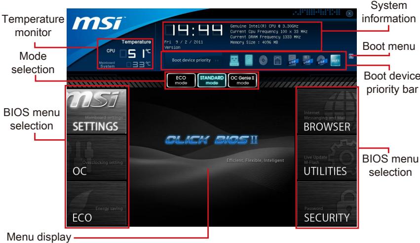
Overview
After entering Click BIOS II, the following screen is displayed.
Important
The pictures in this guide are for reference only and may vary from the product you purchased. Please refer to the actual screens of your system for detailed information.
Temperature monitor
This block shows the temperature of the processor and the mainboard.
System information
This block shows the time, date, CPU name, CPU frequency, DRAM frequency, DRAM capacity and the BIOS version.
BIOS menu selection
These blocks are used to select menus of BIOS. The following options are available:
- SETTINGS - Use this menu to specify your settings for chipset features, boot device.
- OC - This menu contains items of the frequency and voltage adjustments. Increasing the frequency can get better performance, however high frequency and heat can cause instability, we do not recommend general users to overclock.
ECO - This menu is related to energy-saving settings. - BROWSER - This feature is used to enter the MSI Winki web browser.
- UTILITIES - This menu contains utilities for backup and update.
SECURITY - The security menu is used to keep unauthorized people from making any changes to the settings. You can use these security features to protect your system.
Boot device priority bar
You can move the device icons to change the boot priority.
Boot menu
This button is used to open a boot menu. Click the item to boot the system from the device instantly.
Mode selection
This feature allows you to load presets of energy saving or overclocking.
Menu display
This area provides BIOS setting menu that allows you to change parameters.
Boot device priority bar
This bar shows the priority of the boot devices. The light icons indicate that the devices are available.

Click and draw the icon to left or right to specify the boot priority.
Operation
Click BIOS II allows you to control BIOS settings with the mouse and the keyboard. The following table lists and describes the hot keys and the mouse operations.
| Hot key | Mouse | Description |
| <↑↓→←> | Move the cursor | Select Item |
| <Enter> | Click/ Double-click the left button | Select Icon/ Field |
| <Esc> | Click the right button | Jump to the Exit menu or return to the previous from a submenu |
| <++> | Increase the numeric value or make changes | |
| <-> | Decrease the numeric value or make changes | |
| <F1> | General Help | |
| <F4> | CPU Specifications | |
| <F5> | Enter Memory-Z | |
| <F6> | Load optimized defaults | |
| <F10> | Save Change and Reset | |
| <F12> | Save a screenshot to a FAT/FAT32 USB drive |
Sub-Menus
An arrow symbol appears to the left of certain fields that means it contains a sub-menu. A sub-menu contains additional options for a field parameter. You can use arrow keys (↑↓) or mouse to highlight the field and press
General Help
Click BIOS II provides General Help window. You can call up the window from any BIOS menu by simply pressing <F1> or click HELP on BIOS setting screen. The Help window lists the appropriate keys to use and the possible selections for the highlighted item.
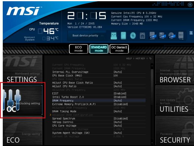
OC Menu
This menu is for advanced users who want to overclock the mainboard.
Important
Overclocking your PC manually is only recommended for advanced users.
- Overclocking is not guaranteed, and if done improperly, can void your warranty or severely damage your hardware.
- If you are unfamiliar with overclocking, we advise you to use OC Genie for easy overclocking.
Current CPU/ DRAM Frequency
These items show the current clocks of CPU and Memory speed. Read-only.
Internal PLL Overvoltage
This item is used to adjust the PLL voltage.
CPU Base Clock (MHz)
This item allows you to set the CPU Base clock (in MHz). You may overclock the CPU by adjusting this value. Please note the overclocking behavior is not guaranteed.
CPU Base Clock Ratio
It shows the CPU Base Clock ratio. Read-only.
Adjust CPU Base Clock Ratio
This item allows you to set the CPU Base Clock ratio.
Adjust CPU Ratio
Controls the multiplier that is used to determine internal clock speed of the processor. This feature can only be changed if the processor supports this function.
Adjusted CPU Frequency
It shows the adjusted CPU frequency. Read-only.
EIST
Enhanced Intel SpeedStep technology allows you to set the performance level of the microprocessor whether the computer is running on battery or AC power. This field only appears with installed CPUs that support this technology.
Intel Turbo Boost 2.0
Enables or disables Intel Turbo Boost 2.0 which automatically boosts CPU performance above rated specifications (when applications requests the highest performance state of the processor).
DRAM Frequency
This item allows you to adjust the DRAM frequency. Please note the overclocking behavior is not guaranteed.
Extreme Memory Profile (X.M.P)
This item is used to enable/disable the Intel Extreme Memory Profile (XMP). For further information please refer to Intel's official website.
Adjusted DRAM Frequency
It shows the adjusted DRAM frequency. Read-only.
DRAM Timing Mode
Select whether DRAM timing is controlled by the SPD (Serial Presence Detect) EEPROM on the DRAM module. Setting to [Auto] enables DRAM timings and the following "Advanced DRAM Configuration" sub-menu to be determined by BIOS based on the configurations on the SPD. Selecting [Link] or [Unlink] allows users to configure the DRAM timings for each channel and the following related "Advanced DRAM Configuration" sub-menu manually.
Advanced DRAM Configuration
Press
Command Rate
This setting controls the DRAM command rate.
tCL
Controls CAS latency which determines the timing delay (in clock cycles) of starting a read command after receiving data.
tRCD
Determines the timing of the transition from RAS (row address strobe) to CAS (column address strobe). The less clock cycles, the faster the DRAM performance.
tRP
Controls number of cycles for RAS (row address strobe) to be allowed to pre-charge. If insufficient time is allowed for RAS to accumulate before DRAM refresh, the DRAM may fail to retain data. This item applies only when synchronous DRAM is installed in the system.
tRAS
Determines the time RAS (row address strobe) takes to read from and write to memory cell.
tRFC
This setting determines the time RFC takes to read from and write to a memory cell.
tWR
Determines minimum time interval between end of write data burst and the start of a pre-charge command. Allows sense amplifiers to restore data to cell.
tWTR
Determines minimum time interval between the end of write data burst and the start of a column-read command; allows I/O gating to overdrive sense amplifies before read command starts.
tRRD
Specifies the active-to-active delay of different banks.
tRTP
Time interval between a read and a precharge command.
tFAW
This item is used to set the tFAW (four activate window delay) timing.
tWCL
This item is used to set the tWCL (Write CAS Latency) timing.
tCKE
This item is used to set the Pulse Width for DRAM module.
tRTL
This item is used to set Round Trip Latency settings.
tXP
Exit Power Down with DLL on to and valid command; Exit Precharge Power Down with DLL frzon to commands not requiring a locked DLL.
= = Advanced Timing Configuration = =
Follwing items are used to set the read/ write timings for memory.
tRRDR
Read-Read Different Rank, same DIMM.
tRRDD
Read-Read Different Rank.
tWWDR
Write-Write Different Rank, same DIMM.
tWWDD
Write-Write Different Rank.
^t RWDRDD
Read-Write Different Ranks same or Different DIMM.
tWRDRDD
Write-Read Different Ranks same or Different DIMM.
tRWSR
Read-Write Same Rank.
Spread Spectrum
This function reduces the EMI (Electromagnetic Interference) generated by modulating clock generator pulses.
Important
-
If you do not have any EMI problem, leave the setting at [Disabled] for optimal system stability and performance. But if you are plagued by EMI, select the value of Spread Spectrum for EMI reduction.
-
The greater the Spread Spectrum value is, the greater the EMI is reduced, and the system will become less stable. For the most suitable Spread Spectrum value, please consult your local EMI regulation.
-
Remember to disable Spread Spectrum if you are overclocking because even a slight jitter can introduce a temporary boost in clock speed which may just cause your overclocked processor to lock up.
V Droop Control
This item is used to select the VDroop control mode.
CPU Core Voltage/ System Agent Voltage (SA)/CPU I/O Voltage/ CPU PLL Voltage/ DDR CH_A/B Voltage/ DDR CH_C/D Voltage/ DDR CH_A CA Vref Voltage/ DDR CH_B CA Vref Voltage/ DDR CH_C CA Vref Voltage/ DDR CH_D CA Vref Voltage/ DDR CH_A DQ Vref Voltage/ DDR CH_B DQ Vref Voltage/ DDR CH_C DQ Vref Voltage/ DDR CH_D DQ Vref Voltage/ PCH 1.1 Voltage/ PCH 1.5 Voltage.
These items are used to adjust the voltage of CPU, Memory and chipset.
Current CPU Core Voltage/ Current SA Voltage/ Current DDR CH_A/B Voltage/ Current DDR CH_C/D Voltage
These items show current CPU/ DRAM voltage. Read-only.
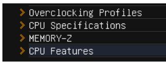
Overclocking Profiles
Press
Overclocking Profile 1/2/3/4/5/6
Press
Set Name for Overclocking Profile 1/2/3/4/5/6
Give a name by typing in this item.
Save Overclocking Profile 1/2/3/4/5/6
Save the current overclocking settings to ROM for selected profile.
Load/ Clear Overclocking Profile 1/2/3/4/5/6
Load/ Clear the stored profile settings from ROM.
Overclocking Profile Save
Save the current overclocking settings to USB flash disk.
Overclocking Profile Load
Load the stored settings from USB flash disk.
OC Retry Count
When overclocking has failed, setting this item to [3,5] will allow system to reboot 3/ 5 times with the same overclocked configuration. If overclocking has failed every time, the system will restore the defaults.
CPU Specifications
Press
CPU Technology Support
Press
MEMORY-Z
Press
> DIMM1~4 Memory SPD
Press
CPU Features
Press
Hyper-Threading Technology
The processor uses Hyper-Threading technology to increase transaction rates and reduces end-user response times. The technology treats the two cores inside the processor as two logical processors that can execute instructions simultaneously. In this way, the system performance is highly improved. If you disable the function, the processor will use only one core to execute the instructions. Please disable this item if your operating system doesn't support HT Function, or unreliability and instability may occur.
Active Processor Cores
This item allows you to select the number of active processor cores.
> Limit CPUID Maximum
It is designed to limit the listed speed of the processor to older operating systems.
Execute Disable Bit
Can prevent certain classes of malicious "buffer overflow" attacks where worms can try to execute code to damage your system. It is recommended you keep this enabled always.
>Intel Virtualization Tech
Enhances virtualization and allows the system to act as multiple virtual systems. See Intel's official website for more information.
Intel VT-D Tech
This item is used to enable/disable the Intel VT-D technology. For further information please refer to Intel's official website.
Power Technology
This item allows you to select the Intel Dynamic Power technology mode.
C1E Support
Enable system to reduce CPU power consumption while idle. Not all processors support Enhanced Halt state (C1E).
OverSpeed Protection
Monitors current CPU draw as well as power consumption; if it exceeds a certain level, the processor automatically reduces its clock speed. For overclocking, it is recommended this feature is disabled.
Intel C-State
C-state is a power management state that detects when the system is idle and lowers power consumption accordingly.
Package C State limit
This field allows you to select a C-state mode.
Long duration power limit (W)
This field allows you to adjust the TDP power limit for the long duration.
Long duration maintained (s)
This field allows you to adjust the maintaining time for long duration power limit.
Short duration power limit (W)
This field allows you to adjust the TDP power limit for the short duration.
Primary plane turbo power limit (W)
These fields allow you to adjust the TDP limit for the primary plane turbo.
1/2/3/4/5/6-Core Ratio Limit
These fields show the 1/2/3/4/5/6 core ratio limit of CPU.
Updating the BIOS with Live Update
This section tells you how to update the BIOS by using the Live Update utility before entering Operating System. Live Update will update the BIOS automatically when connecting to the Internet. To update the BIOS with the Live Update utility:
- Click Live Update button installed).

on the BIOS UTILITIES menu. (The Winki must be
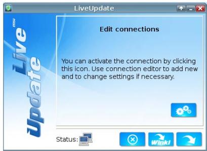
- Setup the connection by click the setting button if necessary.
- Click the next button
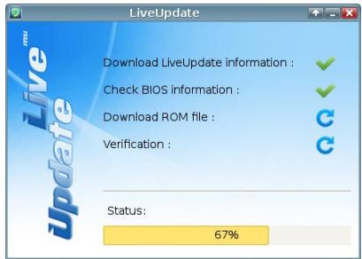
- Live Update will automatically detect the version of BIOS and download the appropriate file.
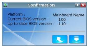
- Click the confirm button to update the BIOS.
Important
Do not update the BIOS if your system is running fine.
Software Information
Take out the Driver/Utility Disc that is included in the mainboard package, and place it into the optical drive. The installation will auto-run, simply click the driver or utility and follow the pop-up screen to complete the installation. The Driver/Utility Disc contains the:
- Driver menu : It provides available drivers. Install the driver by your desire and to activate the device.
- Utility menu : It allows you to install the available software applications.
- Service base menu : Through this menu to link the MSI officially website.
- Product info menu : It shows the newly information of MSI product.
- Security menu : It provides the useful antivirus program.
Important
Please visit the MSI officially website to get the latest drivers and BIOS for better system performance.
Installing Winki
BIOS BROWSER and UTILITIES request Winki, please install the "Winki" software application from MSI Driver Disc in Windows first. And then you can access these two features by clicking their respective buttons.
To install Winki, follow the steps below:
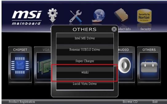
- Power on your computer and enter Windows operating system.
- Insert MSI Driver Disc into the optical drive. The setup screen will automatically appear.
- Click Driver tab.
- Click OTHERS button.
- Select Winki to start installing.
- When finished, restart your computer.

Deutsch
X79MA-GD45
Serie
Spezifikationen
Prozessoren
Frontpanel Anschlüsse: JFP1, JFP2
CPU Specifications
MEMORY-Z
CPU Features
CPU Base Clock Ratio
Adjust CPU Base Clock Ratio
CPU Technology Support
Active Processor Cores
Intel Virtualization Tech
Enhances virtualization and allows the system to act as multiple virtual systems. See Intel's official website for more information.
Intel VT-D Tech
OverSpeed Protection
Package C State limit
Primary plane turbo power limit (W)
Emplacement PCIe (Peripheral Component Interconnect Express)
CPU Specifications
MEMORY-Z
CPU Features
Adjusted CPU Frequency
Adjusted DRAM Frequency
- Current CPU Core Voltage/ Current SA Voltage/ Current DDR CH_A/B Voltage/ Current DDR CH_C/D Voltage
Set Name for Overclocking Profile 1/2/3/4/5/6
CPU Technology Support
Intel Virtualization Tech
OverSpeed Protection
Package C State limit
Long duration power limit (W)
Long duration maintained (s)
Primary plane turbo power limit (W)
ATX (24.4 cm × 24.4 cm)
OTBepctnaIIOyycTaHOBOOHyBbINHTbl
8xKpeNekhbxOTBepctnI
Дя получени Сбедени O приобретени ДОпОннITEьн IX KOMПОHEHTOB I HOMePAX DeTaN 3aIInTe Ha CTpaHnU pOdyKta n BOCNoNb3yI TeCb ПОСКOM Ha Haujem Be6caiTe
http://www.msi.com/index.php
KpaTkoe pyKOBOdTO BO pa3bEmam
CnpaBoHoe pyKoBOdCTBO no pa3bEmam
Cnot PCIe (Peripheral Component Interconnect Express)
Cnot PCIe noidepKnBaet KapTbI paacupeHnIHTepFeca PCIe.
PCIe 3.0 x16 Cnot

PCIe 2.0 x1 Cnot
Bumahxe!
Pn do6ablennn nnn n3Bneuehen nnat pacwnpehna Bcerda Bbiknoaute nntaHne n BbInMaIte shyp nntaHn 13 p03eKn. IpOHTNEdoKymentauNHO h KapTy paCwnepHn N BbINONHtE Heo6xOIMMbte annapaTHBe nnnporpamMbte yctahOBKn dny daHHo nIpaTb, TaKne KaK nepembykN, nepeknouateenn nn konphiynpyaquio BIOS.
Pa3beMbl
Pa3bem SATA: SATA1~6
Даннь pa3bemЯВЯТСВ ВИСКОСКОРСТБИМ ИHTePpeIcOM SATA.Клбому pa3bemy SATA можно NOДКЛЮЧИТ b OДно yCTpoIcTBO SATA.КуSTpoIcTBaM SATA OTHOCY TсДИСКOBОДы (HDD), TВЕРДOTeЛьны HaKONITeJI (SSD) n ONTINueCKne DCCKN (CD/DVD/Blu-Ray).
*Pa3meueHne CnCTeMHNo PnAtbHa npCnuHKe npBvBeHo TOnbko DnI npImepa.
SATA1~2 (6Γ6/c, Ha ochobe Intel® X79)
SATA3~6 (3Γ5/c, Ha ochobe Intel® X79)
Bhumahve!
- Mhorim yctpoiCTbAM SATA TaKke Heo6xOIMO npAOMe IOnkIOueHne K 6IOKy nITAHn. B INX YnCNO BxoJr TnCKOBoBj (HDD), TBepDToJIbHbIe HAKONITeIN (SSD) n ONTueckne DnCKN (CD/DVD/Blu-Ray). DononHTeJIbHbIe CBeJeHn CM. B pyKOBOCTBE NOJIb3OBAteJI K KOHNpeTHOMy yctpoiCTBy.
- Bo Mhorix cncemhix 6nokax kpynhie yctpoiCTBa SATA, B qacthoctn, HDD, SSD n ontuueckne dNCKn, Heo6xOIMo 3aKpeJIyTB BuHTamn. IOnONHITeNbHbIe INCTpykUnn no yctahOBke ppeCTabIeHb B pyKOBOCTBe K CNTcEMHOMy 6nOky nn yctpoiCTBy SATA.
- 136eai Te neperinbo Ka6en SATA ha 90 rpaucob. B npotnbom cnyae moryt BO3HnKHyTb noTeep daHHbx npu nepedaue.
Pa3bembl,Ha oboxKoHax Ka6eY SATA, ndeHTnHyb. Ondako,IJIa 3KOHOMM MeCTa K MaTePHNCKO nnate peKoMeHNdyETcnoKNHOaTb NIOCKn pa3bem.
Pa3bEmblIITaHnBEHTNJIrTOPOB:CPUFAN1,SYSFAN1\~2
B pa3bembl nHTaHnI dIy BeHTnJIrTOpOB pa3peWaaETcYCTAHOBKa BeHTnJIrTOpOB C nHTaHnEM +12 B. Ecnl Ha cNCTeMHo IIaTe IIMeTcY cINcET MoIHrOpa cNCTeMHOrO 6OBpyODaHnB, Bbl DOJIKHbI NCJONLb3OBAbT CNEuAIBHO pa3pa6OTaHHb BeHTnJIrTO pC DaTaNOM CKOPoCTN, YTObbl NCJONLb3OBAbT ynpabJIeHne BeHTnJIrTOpOM npOceCCopa. He 3a6yDbte NOkJIIOUHTB BCE cNCTeMHbE BeHTnJIrTOpBl HeHTnJIrTOpBl MOyT 6bIT He NOkJIIOUHTB K cNCTeMHo IaTe N BMeCTO 3TORO NOkJIIOUHTB K INCTOCHNY PA7HnIHaNpRMyO. BeHTnJIrTO mOKet bbl NOkJIIOUChEN K JIObOMy CBO6oDHomy pa3bemy BeHTnJIrTOpA cNCTeMbl.
CPUFAN1/ SYSFAN1


SYSFAN2
Bhumahvile!
- To6bIyToCHHTbNoHbIcNtCOKNoDepKxNBaEmBXBeHTnJIrTOPOBdPCU,3aJnte, noXaJyIcTa,HaOfUnaJIbHbIcAIT npOn3BOJNTeJIuNNpokOHcyTnpuyTeCb c npoDaVcOM.
Pa3bemblCPUFAN1, SYSFAN1 noidepknBaot ynpaBHeHne ckopocbIb BpaueHnBEHTNlAToPc nHeHbIM pexHMOM. Ipy aTOMatUeCKOro KOHTPOJnCKOpOCTNBeHTNlAToPnOeCCopa, 3aBnCyaJe ot TempeAtypbl npOeCCopa n CnCTEmbl,MOXHOyctAHOBtB Control Center II. - Ecnn Ha MaTePNHcKo nnate HeNoCTaTOUHO nopTob nIy NoDknIOueHnB CEx BENTINrTopOB, Bbl MoKeTe noDknIOuHTb nx HEnOcePdCTBeHHO K 6NOKy NITAHnY uepe3 nepeXoDNHnKi.
-ПередперволзагузкоубдгьВOTCYTCTBnnpOBODOB,КOTOPbIeMOrJIN6bl nonactbNIONACTNBEHTNJTAPOB.
Pazbembl napeDnei naHei:JFP1,JFP2
3Tn pa3bembl nCNoB3yIOTc IJn PNOKJIIOUeHnKHOJOK IN CBEToNDnDhIx INDNkATOpOB, paCNOJoxeHHbIX Ha nepeDne HaneHIn CnCTeMHOro 6Ioka. Pa3bem JFP1 COOTBeTCTByET cTaNdapTy Intel® Front Panel I/O Connectivity Design. IJny npOuSeHn pnoZeDpybl PNOKJIIOUeHn PpeDne HaneHIn, BOCNOB3yIteCb M-KOHNeKTOpAmn. BCTaBtBe BCE npOBOda n3 cnCTeMHOro 6Ioka B M-KOHNeKTOpbl, a 3aTeM B MaTePInHcKyI pIaTy.

Brumahne!
Ha pa3bemaxn3 cncTeMHoro 6Ioka, KOHTaKbI npOBoDOb nnoXKeJIbHOH noJpHOCTHnomeeHbMaHehkbMn TpeyroJIbHNkAmn. IcnoJIb3yIte BblweepuBedeHHble CXEmbI n HauPiNCn Ha M-KohHeKTopax dIy onpeDeIeHn pyabNlbHoro nnoJoxeHnOpneHTaun pa3bemOB.
-Болшинсво pa3bembl Na naHelen nepedHero KOpnyca KomnbTopea B OCHOBHOM 6ydt nodkluyeH K JFP1.
Front Panel Audio Connector: JAUD1
CPU Specifications
MEMORY-Z
CPU Features
Adjusted CPU Frequency
3TOT nyHKT nokazbIbaeTeKyuUO uactOtu CPU.ToIbKO dIy UTeHnA.
EIST
TexHONorra Enhanced Intel SpeedStep no3B0JareyCTaHObntb ypoBeHb npOn3BOUInTeNbHocTn npOeCCopa pnp 3neKtpoNTAHm OT 6aTapeu INIOT cETN. DaHoe nOle npAIBJeTcra TObko B cnlyae ycTaHObKn CPU, noDdepKINBaHOJero 3Tu texHONorru.
Intel Turbo Boost 2.0
3TOT nyHKT nCNOJb3yeTc dIy BKNIOUeHn/ BblKIOUeHn TexHOIOrn Intel Turbo Boost 2.0. OH noBbIaAet yactOToI npOeCCopa, KOrDa npIKNaIbHe InporpaMMbI Tpe6yHOT 6oJIbSeI npOn3BOdInTeNbHocTn, n TDP npOeCCopa 3TO nO3BOJraEeT.
DRAM Frequency
3TOT nyHKT nCIOJIb3yETcI dIy HAcTPOIKN yactOtbl DRAM. O6paTnTe BHMaHne Ha To, cTO ycNEUHOCTb pa3roHa He rapaHTnpyETcI.
Extreme Memory Profile (X.M.P)
3TOT nyHKT no3BOJLaET BKNIOUHTb/BykIIOUHTb Intel Extreme Memory Profile (XMP). 3a. dONONHtJIbHO INΦOpaMaIeN o6paIaITeCb Ha OΦuHaJIbHbY Be6caIT Intel.
Adjusted DRAM Frequency
3TOT nyHKT nokaBbAeTeKyuTo yactOy DRAM.ToIbKO dnyTeHnA.
DRAM Timing Mode
OnpeJeIeT 6yUr IIN TaMmHr DRAM KOHTpOIpoPoBaTbc DaHbIMn n3 SPD (Serial Presence Detect) EEPROM Ha moDyIe DRAM. PIn BbIbOpE 3NaueHnra [Auto] TaMmHr DRAM, BkIIOuA pyHKtB MeHIO, nepeuNcIeHbIe HnKze, yCTaHaBJIbAoiTCra BIOS B COOTBeTCTBn C daHbIMn n3 SPD. YcTaHObKa 3NaueHnra B [Link] nIIIN [Unlink] no3BOJrE TByuHyIO peYImpoBaT b TaMmHr DRAM DoCTyNbIe B 3tOM MeHIO u nepExoDiNb B NOdMeHIO «Advanced DRAM Configuration» («PacuipenHna KOnΦnIrpyaunz DRAM»).
Advanced DRAM Configuration
HaxmTe
Command Rate
- Current CPU Core Voltage/ Current SA Voltage/ Current DDR CH_A/B Voltage/ Current DDR CH_C/D Voltage
3Tи npKtbI noka3bIbaIOT TekuJee HanpJxKeHne CPU core/ DRAM. TOnbko InyaTeHna.
Overclocking Profiles
HaxmTe
Overclocking Profile 1/2/3/4/5/6
Haxmte
Set Name for Overclocking Profile 1/2/3/4/5/6
YkaKInTe NmB 3TOM nOJIe.
Save Overclocking Profile 1/2/3/4/5/6
CoxpaHnTe TeKyuIe NaCTPOuKn pa3OHa IaIy BbIbpaHOrO npoΦnIy Ha 3Y
Load/ Clear Overclocking Profile 1/2/3/4/5/6
Coxpanen/ynaneHne nactpoek npoqnpa3roHa na I3Y.
Overclocking Profile Save
CoXpaHEnHe TeKyuInx HacTpoEk pa3roHa Ha pIeIi-Drck USB.
Overclocking Profile Load
3aRpy3ka coXpaHeHHbIX HacTpoEck cФneu-ДИСka USB.
OC Retry Count
Пи Heydachnom pa3roHe, yctahOBka 3TOrO nykTa B [3, 5] n03BoJare TcNCTeMe nonbIaTbc3arpy3ntbc3/5 pa3a c 3aDaHNoi KOHfHpyaUnei. Ecnn 3arpy3ntbc3 He ydaNaCTbc BCE tpr pa3a, CnCTema BOCCTAHOBNT HAcTPOKn I OymOnuHaHIO.
CPU Specifications
CPU Technology Support
Haxmnte
MEMORY-Z
Haxmnte
DIMM1~4 Memory SPD
Haxmte
CPU Features
Haxmnte
Hyper-Threading Technology
Ipoceccop nCnoJIb3yET texHJIoNIO Hyper-Threading InyBeynueHnna npOn3BOUInTeNbHocTN. 3Ta texHONOrnNo3BOJAreDByM Na6Opam perncTPOB B npOeCCope nCnoINHrTB NHCtpyKcIM OndHOBpeMHNO. 3TO yBeJIuHBAe npOn3BOUInTeNbHocTB CnCTembl. PnB bIKNUeHm 3ToI cyHKm, npOceccop nCnoHNReT INCtpyKcIM c NOMoCbIO OndHOrO Na6Opa rpeHCTPOB. BbIKNUOHTe 3OT npYNKT, KOrda daHHa CnCTema He NODepXkBaet cyHKcIM IO HT, B npOTNBOM clycae 3TO npINBeDE T K HeHaJeXHoCTN HecTaBnJIbHoCTN.
Active Processor Cores
3TOT nyHKT n03BONJET 3aDaTb YnCNo AKTNBbIX JApep npOceccopa.
Limit CPUID Maximum
Intel Virtualization Tech
YnyuetaeBnptyaJIN3aIIOI NIO3BOJrE TcIcTeMe DeIcTBoBaTb KaueCTBe HECKOJIbKINX BnPtyaJIbHbIX CnCTeM. IOnONHITeJIbHbIe CBeDEHnA CM. Ha OoNuaJIbHom Be6-caTe Intel.
Intel VT-D Tech
3TOT nyHKT nCnONb3ayETcA DnI BkNIOUeHnBbIKIOUeHn TExHOJOrnIn Intel VT-D. IOnOJIHHTeNbHbIe CBeDEHnCm. Ha OΦnuaJIbHOM Be6-caITe Intel.
Power Technology
OverSpeed Protection
OcIeKnaeT ToK, nTope6JrEmbI LII, n 3Hepronotpe6JIeHnE; ecn OHO npBeBlaaet OnpEdenHbI yPoBeHb, npoecccop aBTOMaTHueeckn yMeHbIaET TAKTOByu cAtoTy. Pp npa3roHe 3Tu fYHKmIO peKOMeHNyETcR OTKnHouHTb.
Intel C-State
C-state - coctoHne ynpaBHeHn3HeprOOnTepeBHeHnEm, OnpEeJIIOuIeepnoCTOn CnCTembl NpOHJkaUoiue 3HeprOOnTepeBHeHn COOTBeTCTByIOUIM 06pa3OM.
Package C State limit
Данн布局аMuTpo3B0JЯeT bIbpaTbpeKIM C-state.
> Long duration power limit (W)
Даннь памету Incnoь3уетс дя установки п dedьною мочно TDP дя Дпintьног pa6otbl.
> Long duration maintained (s)
Данн布局apametnpICNOLb3yETcIДЯуctaHOBKINВрemeHиO6CnykBaHnЯпуctaHOBKe npedeJIbHOМоцHoCTIДЯДЛNTeJIbHOpa6Tobl.
Short duration power limit (W)
B daHnomone yctaHabnBaetc npedeIbHaMoIHoCTb TDP npKpaTKOBpeMeHHo pa6ote.
Primary plane turbo power limit (W)
- Trademarks
- Technical Support
- Safety Instructions
- FCC-B Radio Frequency Interference Statement
- Notice 1
- Notice 2
- Battery Information
- Chemical Substances Information
- BSMI EMI 聲明
- WEEE (Waste Electrical and Electronic Equipment) Statement
- ENGLISH
- DEUTSCH
- Mainboard Specifications
- Processor Support
- Chipset
- Memory Support
- LAN
- Audio
- SATA
- RAID
- USB 3.0
- Multi-GPU
- Connectors & Buttons
- Back panel
- On-Board
- Slots
- Form Factor
- Mounting Screw Holes
- Connectors Quick Guide
- Back Panel Quick Guide
- Mouse/Keyboard
- Clear CMOS Button
- Coaxial S/PDIF-Out
- Optical S/PDIF-Out
- USB 2.0 Port
- USB 3.0 Port
- Important
- Audio Ports
- CPU (Central Processing Unit)
- Introduction to the LGA2011 CPU
- Overheating
- Replacing the CPU
- Overclocking
- CPU & Cooler Installation
- Power Supply
- ATX 24-pin Power Connector: JPWR1
- ATX 8-pin Power Connector: JPWR2
- Memory
- Quad Channel Memory
- Installing Memory Modules
- Expansion Slots
- PCIe (Peripheral Component Interconnect Express) Slot
- Internal Connectors
- SATA Connector: SATA1~6
- Fan Power Connectors: CPUFAN1,SYSFAN1\~2
- Front Panel Connectors: JFP1, JFP2
- Front Panel Audio Connector: JAUD1
- USB 2.0 Expansion Connectors: JUSB1/ JUSB2
- USB 3.0 Expansion Connector: JUSB3
- Chassis Intrusion Connector: JCI1
- TPM Module connector: JTPM1
- Serial Port Connector: JCOM1
- Voice Genie Connector: JDLED3 (optional)
- MultiConnect Panel Connector:JTURBO1 (optional)
- V-Check Points
- Jumpers
- Clear CMOS Jumper: JBAT1
- Low Temperature Booting Jumper: JCOLD1, JCOLD2
- LED Status Indicators
- CPU_PHASE LEDs
- DIMM WARNING LEDs
- DrMOS_ALARM LED
- HDDLED
- BIOS Setup
- Entering
- Press DEL key to enter Setup Menu, F11 to enter Boot Menu
- Overview
- Boot device priority bar
- Operation
- Sub-Menus
- General Help
- OC Menu
- tRFC
- tWR
- tWTR
- tRRD
- tRTP
- tFAW
- tWCL
- tCKE
- tRTL
- tXP
- tRRDR
- tRRDD
- tWWDR
- tWWDD
- t RWDRDD
- tWRDRDD
- tRWSR
- Spread Spectrum
- V Droop Control
- Overclocking Profiles
- OC Retry Count
- CPU Specifications
- CPU Technology Support
- MEMORY-Z
- > DIMM1~4 Memory SPD
- CPU Features
- Hyper-Threading Technology
- Active Processor Cores
- > Limit CPUID Maximum
- Execute Disable Bit
- >Intel Virtualization Tech
- Intel VT-D Tech
- Updating the BIOS with Live Update
- Software Information
- Installing Winki
- X79MA-GD45
- Serie
- Spezifikationen
- Prozessoren
- Frontpanel Anschlüsse: JFP1, JFP2
- Intel Virtualization Tech
- OverSpeed Protection
- Package C State limit
- Primary plane turbo power limit (W)
- Emplacement PCIe (Peripheral Component Interconnect Express)
- OTBepctnaIIOyycTaHOBOOHyBbINHTbl
- KpaTkoe pyKOBOdTO BO pa3bEmam
- Cnot PCIe (Peripheral Component Interconnect Express)
- Bumahxe!
- Pa3beMbl
- Pa3bem SATA: SATA1~6
- Bhumahve!
- Pa3bEmblIITaHnBEHTNJIrTOPOB:CPUFAN1,SYSFAN1\~2
- Bhumahvile!
- Pazbembl napeDnei naHei:JFP1,JFP2
- Brumahne!
- Power Technology
- Intel C-State
- > Long duration power limit (W)
- > Long duration maintained (s)
- Short duration power limit (W)
Brand : MSI
Model : X79MA-GD45
Category : Motherboard