How to reset the Denon AVR-3808CI to factory settings?
Press and hold the ENTER and STANDBY/ON buttons simultaneously for at least 5 seconds. The display shows 'INITIALIZE'. Release the buttons. All settings will be cleared.
How to connect speakers to this receiver?
Use speaker cables with banana plugs or stripped ends. Connect the terminals corresponding to the channels (FRONT, CENTER, SURROUND, SUBWOOFER). Observe polarity (+/-). Tighten the terminals by hand.
My TV displays no image via HDMI, what should I do?
Check that the HDMI cable is properly connected and that the TV's HDMI input is selected. Make sure the receiver's HDMI output is set to 'Monitor' in the menu. Try another HDMI cable or port.
How to configure the network for audio streaming?
Connect the receiver to your router via an Ethernet cable. In the menu, go to 'Network Setup' and enable 'Network Control'. Use software like Windows Media Player to stream music over the network.
What does the 'Protection Circuit' message mean?
This indicates an overload or short circuit. Immediately turn off the device, check speaker connections (no bare wires touching). Let it cool for several minutes before turning back on.
How to calibrate speakers with Audyssey?
Place the microphone at ear height at the listening position. In the menu, select 'Auto Setup' and follow the on-screen instructions. The receiver will emit test tones and adjust levels and distances automatically.
Can I use 4 ohm speakers with this receiver?
Yes, the AVR-3808CI is compatible with 4 to 16 ohm speakers. For 4 ohm speakers, ensure the impedance is correctly set in the 'Speaker Setup' menu (set to 4 ohms). Watch out for overheating.
How to update the firmware?
Go to the Denon website and download the update file. Copy it to a USB stick. Insert the stick into the USB port on the front of the receiver, turn it on, and follow the instructions in the 'Firmware Update' menu.
How to use the Zone 2 function?
Connect speakers to the second pair of surround terminals. In the menu, enable 'Zone 2' and choose the source. Use the remote to switch between Main Zone and Zone 2.
What to do if the remote control does not work?
Check the batteries (replace if necessary). Make sure no obstacles block the infrared signal. If the problem persists, reset the remote by removing the batteries for 30 seconds.
User questions about AVR-3808CI DENON
0 question about this device. Answer the ones you know or ask your own.
Ask a new question about this device
No questions yet. Be the first to ask one.
Download the instructions for your AV receiver in PDF format for free! Find your manual AVR-3808CI -
DENON and take your electronic device back in hand. On this page are published all the documents necessary for the use of your device. AVR-3808CI by DENON.
USER MANUAL AVR-3808CI DENON
Use this manual in combination with the operating guide displayed on the GUI screen.
GUI Menu Operation ( page 23)
GUI Menu Map ( page 24)
The lightning flash with arrowhead symbol, within an equilateral triangle, is intended to alert the user to the presence of uninsulated "dangerous voltage" within the product's enclosure that may be of sufficient magnitude to constitute a risk of electric shock to persons.
The exclamation point within an equilateral triangle is intended to alert the user to the presence of important operating and maintenance (servicing) instructions in the literature accompanying the appliance.
WARNING:
TO REDUCE THE RISK OF FIRE OR ELECTRIC SHOCK, DO NOT EXPOSE THIS APPLIANCETO RAIN OR MOISTURE.
SAFETY INSTRUCTIONS
Read Instructions - All the safety and operating instructions should be read before the product is operated.
Retain Instructions - The safety and operating instructions should be retained for future reference.
HeedWarnings - All warnings on the product and in the operating instructions should be adhered to.
Follow Instructions - All operating and use instructions should be followed.
Cleaning - Unplug this product from the wall outlet before cleaning. Do not use liquid cleaners or aerosol cleaners.
Attachments - Do not use attachments not recommended by the product manufacturer as they may cause hazards.
Water and Moisture - Do not use this product near water - for example, near a bath tub, wash bowl, kitchen sink, or laundry tub; in a wet basement; or near a swimming pool; and the like.
Accessories - Do not place this product on an unstable cart, stand, tripod, bracket, or table. The product may fall, causing serious injury to a child or adult, and serious damage to the product. Use only with a cart, stand, tripod, bracket, or table recommended by the manufacturer, or sold with the
product. Any mounting of the product should follow the manufacturer's instructions, and should use a mounting accessory recommended by the manufacturer.
A product and cart combination should be moved with care. Quick stops, excessive force, and uneven surfaces may cause the product and cart combination to overturn.
Ventilation - Slots and openings in the cabinet are provided for ventilation and to ensure reliable operation of the product and to protect it from overheating, and these openings must not be blocked or covered. The openings should never be blocked by placing the product on a bed, sofa, rug, or other similar surface. This product should not be placed in a built-in installation such as a bookcase or rack unless proper ventilation is provided or the manufacturer's instructions have been adhered to.
Power Sources - This product should be operated only from the type of power source indicated on the marking label. If you are not sure of the type of power supply to your home, consult your product dealer or local power company. For products intended to operate from battery power, or other sources, refer to the operating instructions.
Grounding or Polarization - This product may be equipped with a polarized alternating-current line plug (a plug having one blade wider than the other). This plug will fit into the power outlet only one way. This is a safety feature. If you are unable to insert the plug fully into the outlet, try reversing the plug. If the plug should still fail to fit, contact your electrician to replace your obsolete outlet. Do not defeat the safety purpose of the polarized plug.
Power-Cord Protection - Power-supply cords should be routed so that they are not likely to be walked on or pinched by items placed upon or against them, paying particular attention to cords at plugs, convenience receptacles, and the point where they exit from the product.
Outdoor Antenna Grounding - If an outside antenna or cable system is connected to the product, be sure the antenna or cable system is grounded so as to provide some protection against voltage surges and built-up static charges. Article 810 of the National Electrical Code, ANSI/NFPA 70, provides information with regard to proper grounding of the mast and supporting structure, grounding of the lead-in wire to an antenna discharge unit, size of grounding conductors, location of antenna-discharge unit, connection to grounding electrodes, and requirements for the grounding electrode. See Figure A.
Lightning - For added protection for this product during a lightning storm, or when it is left unattended and unused for long periods of time, unplug it from the wall outlet and disconnect the antenna or cable system. This will prevent damage to the product due to lightning and power-line surges.
Power Lines - An outside antenna system should not be located in the vicinity of overhead power lines or other electric light or power circuits, or where it can fall into such power lines or circuits. When installing an outside antenna system, extreme care should be taken to keep from touching such power lines or circuits as contact with them might be fatal.
Overloading - Do not overload wall outlets, extension cords, or integral convenience receptacles as this can result in a risk of fire or electric shock.
Object and Liquid Entry - Never push objects of any kind into this product through openings as they may touch dangerous voltage points or short-out parts that could result in a fire or electric shock. Never spill liquid of any kind on the product.
Servicing - Do not attempt to service this product yourself as opening or removing covers may expose you to dangerous voltage or other hazards. Refer all servicing to qualified service personnel.
Damage Requiring Service - Unplug this product from the wall outlet and refer servicing to qualified service personnel under the following conditions:
a) When the power-supply cord or plug is damaged,
b) If liquid has been spilled, or objects have fallen into the product,
c) If the product has been exposed to rain or water,
d) If the product does not operate normally by following the operating instructions. Adjust only those controls that are covered by the operating instructions as an improper adjustment of other controls may result in damage and will often require extensive work by a qualified technician to restore the product to its normal operation,
e) If the product has been dropped or damaged in any way, and
f) When the product exhibits a distinct change in performance - this indicates a need for service.
Replacement Parts - When replacement parts are required, be sure the service technician has used replacement parts specified by the manufacturer or have the same characteristics as the original part. Unauthorized substitutions may result in fire, electric shock, or other hazards.
Safety Check - Upon completion of any service or repairs to this product, ask the service technician to perform safety checks to determine that the product is in proper operating condition.
Wall or Ceiling Mounting - The product should be mounted to a wall or ceiling only as recommended by the manufacturer.
Heat - The product should be situated away from heat sources such as radiators, heat registers, stoves, or other products (including amplifiers) that produce heat.
FCC INFORMATION (For US customers)
1. COMPLIANCE INFORMATION
Product Name: AV Surround Receiver
Model Number: AVR-3808CI
This product complies with Part 15 of the FCC Rules. Operation is subject to the following two conditions: (1) this product may not cause harmful interference, and (2) this product must accept any interference received, including interference that may cause undesired operation.
Denon Electronics (USA), LLC
(a D & M Holdings Company)
100 Corporate Drive
Mahwah, NJ 07430-2041
Tel. (800) 497-8921
2. IMPORTANT NOTICE: DO NOT MODIFY THIS PRODUCT
This product, when installed as indicated in the instructions contained in this manual, meets FCC requirements. Modification not expressly approved by DENON may void your authority, granted by the FCC, to use the product.
3. NOTE
This product has been tested and found to comply with the limits for a Class B digital device, pursuant to Part 15 of the FCC Rules. These limits are designed to provide reasonable protection against harmful interference in a residential installation.
This product generates, uses and can radiate radio frequency energy and, if not installed and used in accordance with the instructions, may cause harmful interference to radio communications. However, there is no guarantee that interference will not occur in a particular installation. If this product does cause harmful interference to radio or television reception, which can be determined by turning the product OFF and ON, the user is encouraged to try to correct the interference by one or more of the following measures:
Reorient or relocate the receiving antenna.
Increase the separation between the equipment and receiver.
Connect the product into an outlet on a circuit different from that to which the receiver is connected.
Consult the local retailer authorized to distribute this type of product or an experienced radio/TV technician for help.
This Class B digital apparatus complies with Canadian ICES-003.
Accessories 2
Cautions on Handling 3
Cautions on Installation 3
About the Remote Control Unit 3
Inserting the Batteries 3
Operating Range of the Remote Control Unit 3
Part Names and Functions 4
Front Panel 4
Display 4
Rear Panel 5
Remote Control Unit 6
Connections
Preparations 7
Cables Used for Connections 7
Video Conversion Function 8
Speaker Connections 9
Speaker Installation 9
Speaker Connections 9, 10
Connecting Equipment with HDMI connectors 11
Connecting the Monitor 12
Connecting thePlayback Components 12
DVD Player 12
Record Player 13
CD Player 13
iPod® 13
TV/CABLE Tuner 14
Satellite Receiver 14
Connecting the Recording Components 15
Digital Video Recorder 15
Video Cassette Recorder 15
CD Recorder / MD Recorder / Tape Deck 16
Connections to Other Devices 16
Components Equipped with a DENON LINK connector 16
Video Camera / Game Console 17
Component with Multi-channel Output connectors 17
External Power Amplifier 17
USB Port 18
XM connector 18
Antenna terminals 19
Network Audio 20
Multi Zone 21
External Controller 21
Connecting the Power Cord 22
Once Connections are Completed 22
GUI Menu Operations
Example of the Display of the GUI Mark at a Title 23
Example of Display of Default Values 23
Examples of GUI Screen Displays 23
Example: Browse Menu (Top Menu) 23
Example: Menus with Illustrations (Auto Setup) 23
Cursor Position Display 23
Operations 23
GUI Menu Map 24
Play 37
2 Auto Preset 37
3 Preset Skip 37
4 Preset Name 37
5 Input Mode 37, 38
6 Rename 38
7 Other 38
8Playback Mode (iPod) 38
9 Assign 39
10Playback Mode 39
11 Antenna Aiming 40
Surround Modes
Standard Playback 40
SurroundPlaybackof2-channelSources 40
Playing Multi-channel Sources (Dolby Digital, DTS, etc.) 40
DSP Simulation Playback 41
Stereo Playback 41
DirectPlayback 41
Playback in the Pure Direct Mode 41
Registering Internet Radio Stations as Your Favorites
53
Playing Files Stored on a Computer
54
Playing Files Stored on USB Memory Devices
54
Operating the AVR-3808CI Using a Browser (Web control)
55
Other Operations and Functions
Other Operations
55
Playing Super Audio CDs
56
Recording on an External Device (REC OUT mode)
56
Convenient Functions
56
Channel Level
56
Fader Function
56
Quick Select Function
57
Personal Memory Plus Function
57
Last Function Memory
57
Backup Memory
57
Panel Lock Mode
58
Remote Lock Mode
58
Resetting the Microprocessor
58
Remote Control Unit Operations
Main Remote Control Unit
59
Operating DENON Audio Components
59
Presetting
59
Operating Preset Components
59 ~ 61
Setting the Remote ID
62
Learning Function
62
System Call Function
63
Punch Through Function
63
Setting the Time the Backlight Stays Lit
63
Adjusting the Backlight's Brightness
64
Resetting the Main Remote Control Unit
64
Sub Remote Control Unit Operations
65, 66
Switching Zones
67
Setting the Zone for Which the Sub Remote Control Unit is Used (ZONE SELECT LOCK Mode)
67
Setting the Remote ID
67
Resetting the Settings
67
Amp Assign / Multi Zone Connections and Operations
Multi-Zone Settings with the Amp Assign Function
68, 69
Multi-Zone Settings and Operations with Zone Pre-out Output
70
Multi-Zone Operations
71
Turning the Power On and Off
71
Selecting the Input Source
71
Adjusting the Volume
71
Turning off the Sound Temporarily
71
Other Information
72 ~ 81
Troubleshooting
82 ~ 85
Specifications
85, 86
List of preset codes End of this manual
Getting Started
Thank you for purchasing this DENON product. To ensure proper operation, please read these owner's manual carefully before using the product.
After reading them, be sure to keep them for future reference.
Accessories
Check that the following parts are supplied with the product.
Cautions on Handling
- Before turning the power switch on
Check once again that all connections are correct and that there are no problems with the connection cables.
Power is supplied to some of the circuitry even when the unit is set to the standby mode. When traveling or leaving home for long periods of time, be sure to unplug the power cord from the power outlet.
- About condensation
If there is a major difference in temperature between the inside of the unit and the surroundings, condensation (dew) may form on the operating parts inside the unit, causing the unit not to operate properly.
If this happens, let the unit sit for an hour or two with the power turned off and wait until there is little difference in temperature before using the unit.
- Cautions on using mobile phones
Using a mobile phone near this unit may result in noise. If so, move the mobile phone away from this unit when it is in use.
- Moving the unit
Turn off the power and unplug the power cord from the power outlet.
Next, disconnect the connection cables to other system units before moving the unit.
Note that the illustrations in these instructions may differ from the actual unit for explanation purposes.
Cautions on Installation
Note:
For proper heat dispersal, do not install this unit in a confined space, such as a bookcase or similar enclosure.
About the Remote Control Unit
In addition to the AVR-3808CI, the included main remote control unit (RC-1068) can also be used to operate the equipment listed below.
① DENON system components
② Non-DENON system components
By setting the preset memory ( page 59 ~ 61)
By using the learn function (12 page 62)
Inserting the Batteries
① Lift the clasp and remove the rear lid.
(RC-1068)
(RC-1070)
② Load the two batteries properly as indicated by the marks in the battery compartment.
(RC-1068)
(RC-1070)
③ Put the rear cover back on.
NOTE
Replace the batteries with new ones if the set does not operate even when the remote control unit is operated close to the unit.
The supplied batteries are only for verifying operation.
When inserting the batteries, be sure to do so in the proper direction, following the “ ” and “ ” marks in the battery compartment.
To prevent damage or leakage of battery fluid:
Do not use a new battery together with an old one.
Do not use two different types of batteries
Do not attempt to charge dry batteries.
Do not short-circuit, disassemble, heat or dispose of batteries in flames.
If the battery fluid should leak, carefully wipe the fluid off the inside of the battery compartment and insert new batteries.
Remove the batteries from the remote control unit if it will not be in use for long periods.
When replacing the batteries, have the new batteries ready and insert them as quickly as possible.
Operating Range of the Remote Control Unit
Point the remote control unit at the remote sensor when operating it.
NOTE
The set may function improperly or the remote control unit may not operate if the remote control sensor is exposed to direct sunlight, strong artificial light from an inverter type fluorescent lamp or infrared light.
Part Names and Functions
For buttons not explained here, see the page indicated in parentheses ( ).
Front Panel
[With the door open]
1 Power operation button
(ON/STANDBY) (46)
2 Power indicator (46)
3 Power switch (ON OFF) (46)
4 QUICK SELECT buttons / indicators (57)
MASTER VOLUME control knob (46)
Master volume indicator
7 Display
USB port (18) DIRECT/STEREO button (41)
STATUS button (45) PURE DIRECT button (41)
AUDIO DELAY button (44) DSP SIMULATION button (41)
RESTORER button (43) STANDARD button (40)
Display
1 Input signal indicators
2 Input signal channel indicators
These light when digital signals are input.
3 Information display
The input source name, surround mode, setting values and other information are displayed here.
Output signal channel indicators
Surround speaker indicators
These light according to the settings of the surround A and B speakers.
Master volume indicator
AUDYSSEYMULTEQXTindicator
This lights when the room equalizer is selected.
Recording output source indicator
This lights when the REC OUT mode is selected.
9 NIGHT indicator
This lights when the night mode is selected.
10 Multi zone indicators
These light when the power for the respective zone is turned on.
1 RESTORER indicator
This lights when the RESTORER mode is selected.
12 AL24 indicator
This lights when AL24 Processing Plus is activated (1 page 74).
D.LINK indicator
This lights when playing using DENON LINK connections.
14 Input mode indicators
15 HDMI indicator
This lights when playing using HDMI connections.
16 Decoder indicators
These light when the respective decoders are operating.
Tuner reception mode indicators
These light according to the reception conditions when the input source is set to "TUNER."
AUTO
These light when in the auto tuning mode.
STEREO
In the FM mode, these light when receiving analog stereo broadcasts.
TUNED
Lights when the broadcast is properly tuned in.
Rear Panel
RS-232C connector (21)
2 REMOTE CONTROL jacks (21)
3 TRIGGER OUT jacks (21)
FM/AM antenna terminals (TUNER ANTENNA) (19)
DOCK CONTROL jack (13)
6 Speaker terminals (SPEAKERS) (9)
7 AC OUTLETS (22)
AC inlet (AC IN) (22)
9 Digital audio connectors (OPTICAL / COAXIAL) (12, 14)
ETHERNET connector (20)
USB port (18)
XM connector (SATTU) (18)
DENON LINK connector (16)
14 COMPONENTVIDEO connectors (12)
15 HDMI connectors (11)
16VIDEO/S-VIDEO connectors (12)
17 Analog audio connectors (AUDIO) (12)
PRE OUT connectors (17, 21)
EXT.IN connectors (17)
20 SIGNAL GND terminal (13)
Remote Control Unit
Main remote control unit (RC-1068)
Signal transmission indicator (59)
2 Mode select buttons (59)
3 Quick select / System call buttons (57, 63)
4 Surround mode buttons (40, 41)
System buttons (60, 61)
Audio delay button (A. DL) (44)
7 Tuner system buttons (47)
Input mode button (INPUT) (38)
9 MENU button (23)
10 Cursor buttons ( ) (23)
Parameter / Search button (PARA / SRCH) (41, 49, 50)
HOME button (59)
13 Channel buttons (CH) (47)
14 Input source select / Number buttons... (36, 47)
Remote control signal transmitter (3)
16 Device select indicators (DEV1 / DEV2) …(59)
17 ZONE3 select indicators (Z3) (71)
18 RESTORER button (RSTR) (43)
Night button (NGT) (44)
Test tone button (TEST) (29)
② Surround speaker select button (SPKR) ……(29)
2 POWER buttons (46)
23 Channel select (CH SEL) / ENTER button (23, 56)
24 Return button (RTN) (23)
25 Master volume control buttons (VOL) (46)
26Muting button (MUTE) (46, 71)
27 Main remote control unit setup button (RC SETUP) (59)
The time for which the backlight stays on can be changed ( page 63 "Setting the Time the Backlight Stays Lit").
NOTE
The M. SEL, DTU buttons cannot be used.
The ZONE2 mode QUICK SELECT (1 ~ 3), A.DL, RSTR, NGT, INPUT, SPKR, TEST and surround mode buttons cannot be used.
The ZONE4 mode cannot be used.
Sub remote control unit (RC-1070)
1 ZONE indicators (67)
2 Advanced setup button (67)
3 Input source select buttons (36)
4 CHANNEL buttons (47)
5 SHIFT button (47)
6 MENU button (23)
7 Cursor buttons ( ) (23)
SEARCH button (49, 50)
9 REPEAT button (50)
10 RANDOM button (50)
Remote control signal transmitter (3)
12 ZONE SELECT button (67)
Zone power on/off buttons (ZONE ON/ZONE OFF) (71)
Master volume control buttons (VOLUME) (65, 66)
15 Muting button (MUTE) (46, 71)
16 ENTER button (23)
RETURN button (23)
13 System buttons (47, 65)
19 ALL MUSIC/FAVORITES (DIRECT PLAY) button (65)
20 USB (DIRECT PLAY) button (65)
NOTE
The AUX-1, AUX-2, AUX-3, DTU, DVR-2 and OPTION buttons cannot be used.
Connections
Connections for all compatible audio and video signal formats are described in these operating instructions. Please select the types of connections suited for the equipment you are connecting. With some types of connections, certain settings must be made on the AVR-3808CI. For details, refer to the instructions for the respective connection items below.
NOTE
Do not plug in the power cord until all connections have been completed.
When making connections, also refer to the operating instructions of the other components.
Be sure to connect the left and right channels properly (left with left, right with right).
Do not bundle power cords together with connection cables. Doing so can result in humming or noise.
Preparations
Cables Used for Connections
Select the cables according to the equipment being connected.
Audio cables
Video cables
Coaxial digital connections
(Orange) Coaxial digital (75 Ω/ohms pin-plug) cable
Component video connections
(Green) (Y)
(Blue) (Pb/CB)
(Red) (PR/CR)
Optical digital connections
Optical cable
Component video cable
Analog connections (stereo)
(White) (Red) Stereo pin-plug cable
S-Video connections
S-Video cable
Analog connections (monaural, for subwoofer)
(Black) Pin-plug cable
Video connections
(Yellow) 75 Ω/ohms pin-plug video cable
DENON LINK connections
DENON LINK cable
Audio and video cables
Speaker connections
+ - Speaker cables
HDMI connections
19-pin HDMI cable
Network connections
Ethernet cable
Signal direction
Audio signal: Video signal:
Output Input Output Input Output
Input Output
Video Conversion Function
This function automatically converts various formats of video signals input to the AVR-3808CI into the format used to output the video signals from the AVR-3808CI to a monitor.
The AVR-3808CI's video input/output circuitry is compatible with the following four types of video signals:
Digital video signals: HDMI
Analog video signals: Component video, S-Video and Video
[Flow of video signals inside the AVR-3808CI]
: When 480i/576i signals are input in the main zone
[Flow of video signals for ZONE2]
When not using this function, connect a monitor output with the same type of connector as the video input connector.
The resolution of the HDMI input-compatible monitor connected to the AVR-3808CI can be checked at GUI menu "Information" - "HDMI Information" - "Monitor" (12 page 45).
NOTE
HDMI signals cannot be converted into analog signals.
- 1080p component input video signals cannot be output to anything other than component video connectors.
- 480p/576p, 1080i and 720p component video input signals cannot be converted into S-Video or Video format.
Speaker Connections
Speaker Installation
The illustration below shows a basic example of installation of the amplifier combined with 8 speakers and a monitor.
Front speakers
Place the front speakers to the sides of the monitor or screen and as flush with the screen surface as possible.
The table below shows a typical speaker configuration for the AVR-3808CI.
When using just one surround back speaker, connect it to the left channel (SBL).
NOTE
By default, the AVR-3808CI's "Amp Assign" setting is set to "ZONE2". To use as the surround back speaker for the main zone, change the "Amp Assign" setting (12) page 68, 69).
Connecting the Speaker Cables
Carefully check the left (L) and right (R) channels and + (red) and - (black) polarities on the speakers being connected to the AVR-3808CI, and be sure to interconnect the channels and polarities correctly.
1 Peel off about 0.03ft / 10mm of sheathing from the tip of the speaker cable, then either twist the core wire tightly or terminate it.
2 Turn the speaker terminal counterclockwise to loosen it.
3 Insert the speaker cable's core wire to the hilt into the speaker terminal.
4 Turn the speaker terminal clockwise to tighten it.
When using a banana plug
Tighten the speaker terminal firmly before inserting the banana plug.
NOTE
Use speakers with an impedance of 6 to 16/ohms . When using surround A and B speakers simultaneously, use speakers with an impedance of 8 to 16/ohms .
Connect the speaker cables in such a way that they do not stick out of the speaker terminals. The protection circuit may be activated if the core wires touch the rear panel or if the + and - sides touch each other (“Protection circuit”).
Never touch the speaker terminals while the power supply is connected. Doing so could result in electric shock.
Protection circuit
If speakers with an impedance lower than specified (for example 4 Ω/ohms speakers) are used for an extended period of time with the volume turned up high, the temperature may rise, activating the protection circuit.
When the protection circuit is activated, the speaker output is shut off and the power indicator flashes red. If this happens, unplug the power cord, then check the speaker cable and input cable connections. If the set is extremely hot, wait for it to cool off and improve ventilation around it. Once this is done, plug the power cord back in and turn the set's power back on.
If the protection circuit is activated again even though there are no problems in the ventilation around the set nor in the connections, the set may be damaged. Turn the power off, then contact a DENON service center.
Connecting Equipment with HDMI connectors
With HDMI connections, the video and audio signals can be transferred with a single cable.
The AVR-3808CI is equipped for HDMI version 1.3a. This version is compatible with other versions, allowing connection to all components equipped with an HDMI connector.
※ The AVR-3808CI is compatible with 30- and 36-bit Deep Color.
Compatible audio format
Details
Discs (examples)
2-channel linear PCM
2ch 32-192 kHz 16/20/24 bits
CD, DVD-Video, DVD-Audio
Multi-channel linear PCM
8ch 32-192 kHz 16/20/24 bits
DVD-Audio
Dolby Digital, DTS
Bitstream
DVD-Video
DSD
2/5.1ch 2.8224 MHz 1 bit
SACD
Dolby Digital Plus, Dolby TrueHD, DTS-HD
Bitstream
HD DVD, Blu-ray Disc
Copyright protection system (HDCP)
In order to play the digital video and audio signals of a DVD-Video or DVD-Audio disc using HDMI/DVI connections, both the connected DVD player and monitor must be equipped for a copyright protection system called "HDCP" (Highbandwidth Digital Content Protection).
HDCP is a copy protection technology consisting of data encoding and mutual identification of the devices.
The AVR-3808CI is HDCP-compatible. For details on the DVD player or monitor you are using, refer to its operating instructions.
NOTE
Use a CPPM-compatible DVD player to play DVD-Audio discs that are copyright-protected by CPPM.
The AVR-3808CI cannot be controlled from another device via the HDMI cable.
The audio signals output from the HDMI connector (sampling frequency, bit rate, etc.) may be restricted by the connected device.
Video signals are not output properly when using devices that are not HDCP-compatible.
Video signals are not output if the input video signals do not match the monitor's resolution. In this case, switch the DVD player's resolution to a resolution with which the monitor is compatible.
If the GUI menu "Manual Setup" - "HDMI Setup" - "Audio" setting (10 page 30) is set to "Amp", the sound may be interrupted when the monitor's power is turned off.
Use a cable on which the HDMI logo is indicated (a certified HDMI product) for connection to the HDMI connector. Normal playback may not be possible when using a cable other than one on which the HDMI logo is indicated (a non-HDMI-certified product).
If the monitor or DVD player does not support deep color, deep color signal transfer is not possible.
If the monitor or DVD player does not support xvYCC, xvYCC signal transfer is not possible.
If the monitor does not support "Auto Lipsync Correction" function, this function will not work.
When the AVR-3808CI and DVD player are connected using an HDMI cable, also connect the AVR-3808CI and monitor using an HDMI cable.
If the connected monitor or DVD player only has a DVI-D connector, use an HDMI/DVI converter cable. When using a DVI cable, no audio signals are transmitted.
Use a Deep Color compatible cable for connection to Deep Color compatible devices.
When connecting with an HDMI/DVI converter cable (adapter)
HDMI video signals are theoretically compatible with the DVI format.
When connecting to a monitor, etc., equipped with a DVI-D connector, connection is possible using an HDMI/DVI converter cable, but depending on the combination of components in some cases the video signals will not be output.
When connecting using an HDMI/DVI converter adapter, the video signals may not be output properly due to poor connections with the connected cable, etc.
By default, the HDMI audio signals are output from the speakers connected to the AVR-3808CI.
To output the sound from the TV, make the settings at GUI menu "Manual Setup" - "HDMI Setup" - "Audio" - "TV" (2 page 30).
Connecting the Monitor
Connect the cables to be used (12 page 8 "Video Conversion Function").
With HDMI connections, the video and audio signals can be transferred with a single cable.
To output the audio signals to the monitor with HDMI connections, set GUI menu "Manual Setup" - "HDMI Setup" - "Audio" to "TV" (12 page 30).
NOTE
The component video connectors may be indicated differently on your monitor. For details, see the monitor's operating instructions.
No audio signals are output from the HDMI monitor output connector. To play the sound by monitor, make analog or digital audio output connections to monitor's audio input connectors.
The audio signals output from the HDMI connectors are only the HDMI input signals. Video-converted HDMI signals are not included in the audio signals.
Connecting thePlayback Components
Carefully check the left (L) and right (R) channels and the inputs and outputs, and be sure to interconnect correctly.
DVD Player
Connect the cables to be used.
With HDMI connections, the video and audio signals can be transferred with a single cable.
Connect an HDP (High-Definition Player) in the same way.
When using an optical cable for the digital audio connection, make the settings at GUI menu "Source Select" - "DVD" - "Assign" - "Digital" (12 page 39).
Record Player
When connecting a record player with an MC cartridge, use a commercially available MC head amplifier or a step-up transformer.
Induction humming (a booming sound) may be produced from the speakers if the volume is raised with no record player connected.
With some record players, noise may be generated when the ground wire is connected. If so, disconnect the ground wire.
NOTE
The AVR-3808CI's SIGNAL GND terminal is meant to reduce noise when a record player is connected. This is not a safety ground terminal.
CD Player
Connect the cables to be used.
When using an optical cable for the digital audio connection, make the settings at GUI menu "Source Select" - "CD" - "Assign" - "Digital" (t page 39).
iPod®
Use a DENON Control Dock for iPod (ASD-1R, sold separately) to connect the iPod to the AVR-3808CI. For instructions on the Control Dock for iPod settings, refer to the Control Dock for iPod's operating instructions.
Example :
With the default settings, the iPod can be used connected to the VCR (iPod) connector.
To assign the iPod to a connector other than VCR (iPod), make the settings at GUI menu "Source Select" - "(input source to which iPod dock assigned)" - "Assign" - "iPod dock" (页面 39).
TV/CABLE Tuner
Connect the cables to be used.
When using an optical cable for the digital audio connection, make the settings at GUI menu "Source Select" - "TV/CBL" - "Assign" - "Digital" ( page 39).
Satellite Receiver
Connect the cables to be used.
When using a coaxial digital cable for the digital audio connection, make the settings at GUI menu "Source Select" - "SAT" - "Assign" - "Digital" (10 page 39).
When using a component video cable for the video connection, make the settings at GUI menu "Source Select" - "SAT" - "Assign" - "Component" (47 page 39).
Connecting the Recording Components
Carefully check the left (L) and right (R) channels and the inputs and outputs, and be sure to interconnect correctly.
Digital Video Recorder
Connect the cables to be used.
Make analog connections if you wish to record analog audio signals.
When recording to a digital video recorder, it is necessary that the type of cable used with the playback source equipment be the same type that is connected to the AVR-3808CI DVR OUT connector.
Example: TV IN S-Video cable : DVR OUT S-Video cable
TV IN Video cable : DVR OUT Video cable
- When using a component video cable for the video connection, make the settings at GUI menu "Source Select" - "DVR" - "Assign" - "Component" (12 page 39).
NOTE
Do not connect the output of the component connected to the AVR-3808CI's OPTICAL2 output connector to any input connector other than OPTICAL2.
Video Cassette Recorder
Connect the cables to be used.
When recording to a VCR, it is necessary that the type of cable used with the playback source equipment be the same type that is connected to the AVR-3808CI VCR OUT connector.
Example: TV IN S-Video cable : VCR OUT S-Video cable
TV IN Video cable : VCR OUT Video cable
- When using a component video cable for the video connection, make the settings at GUI menu "Source Select" - "VCR" - "Assign" - "Component" (12 page 39).
NOTE
Do not connect the output of the component connected to the AVR-3808CI's OPTICAL3 output connector to any input connector other than OPTICAL3.
CD Recorder / MD Recorder / Tape Deck
Make analog connections if you wish to record analog audio signals, or digital connections if you wish to record digital audio signals, depending on the types of connectors on the components being used.
CD recorder /
NOTE
Do not connect the output of the component connected to the AVR-3808CI's OPTICAL3 output connector to any input connector other than OPTICAL3.
Connections to Other Devices
Carefully check the left (L) and right (R) channels and the inputs and outputs, and be sure to interconnect correctly.
Components Equipped with a DENON LINK connector
Multi-channel playback is possible with DVD-Audio discs, Super Audio CDs, etc.
To use with DENON LINK connections, make the settings at GUI menu "Source Select" - "Assign" - "Digital" - "DENON LINK" (12 page 39).
Video Camera / Game Console
Component with Multi-channel Output connectors
To play the analog input signals input to the EXT. IN connectors, press the INPUT MODE button on the main unit or INPUT button on the main remote control unit and select "EXT. IN" or make the settings at GUI menu "Source Select" - "(input source)" - "Input Mode" - "Input Mode" - "EXT. IN" (10 page 37).
The video signal can be connected in the same way as a DVD player (12 page 12).
To play copyright-protected discs, connect the AVR-3808CI's EXT. IN connector with the DVD player's analog multi-channel output connector.
External Power Amplifier
When using just one surround back speaker, connect it to the left channel (SBL).
USB Port
Front panel
Rear panel
In the initial status, USB memory devices can be used by connecting them to the USB port on the front panel.
To change the port to be used, see "USB Select" on page 39.
For instructions on playing the files on a USB memory device, see page 54.
NOTE
Set to the USB port you want to use.
The AVR-3808CI is equipped with two USB ports, one each on the front and rear panels. It is not possible to use the set with USB memory devices connected to both the ports at the same time. Select the USB port you want to use at the "Source Select" - "NET/USB" - "Playback Mode" - "USB Select" menu.
XM connector
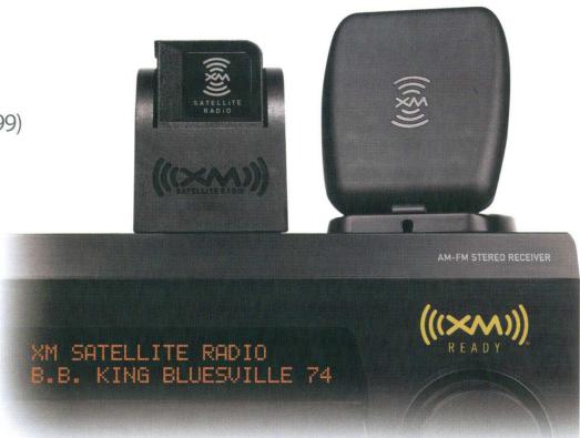
The AVR-3808CI is an XM Ready® receiver. You can receive XM® Satellite Radio by connecting to the XM Mini-Tuner and Home Dock (includes home antenna, sold separately) and subscribing to the XM service.
Plug the XM Mini-Tuner and Home Dock into the XM connector on the rear panel.
Position the Home Dock antenna near a south-facing window to receive the best signal.
For details, see "Listening to XM Satellite Radio Programs" (page 48, 49).
When making connections, also refer to the operating instructions of the XM Mini-Tuner and Home Dock.
NOTE
Keep the power cord unplugged until the XM Mini-Tuner and Home Dock connection have been completed.
The XM name and related logo are registered trademarks of XM Satellite Radio Inc. All rights reserved.
XM Ready is a registered trademark of XM Satellite Radio Inc. All rights reserved.
Antenna terminals
An F-type FM antenna cable plug can be connected directly.
Ground
AM loop antenna assembly
Remove the vinyl tie and take out the connection line.
a. With the antenna on top of any stable surface.
Mount
Connect to the AM antenna terminals.
Bend in the reverse direction.
b. With the antenna attached to a wall.
Installation hole Mount on wall, etc.
Connection of AM antennas
Push the lever.
Insert the 3. Return the conductor. lever.
NOTE
Do not connect two FM antennas simultaneously.
Even if an external AM antenna is used, do not disconnect the AM loop antenna.
Make sure the AM loop antenna lead terminals do not touch metal parts of the panel.
Note to CATV system installer:
This reminder is provided to call the CATV system installer's attention to Article 820-40 of the NEC which provides guidelines for proper grounding and, in particular, specifies that the cable ground shall be connected to the grounding system of the building, as close to the point of cable entry as practical.
Network Audio
Required system
□ Broadband Internet connection
A broadband line connection to the Internet is required in order to use the AVR-3808CI's Internet radio function and firmware update.
Modem
This is a device that is connected to the broadband line to communicate with the Internet. Some are integrated with the router.
Router
When using the AVR-3808CI, we recommend you use a router equipped with the following functions:
Built-in DHCP (Dynamic Host Configuration Protocol) server
This function automatically assigns IP addresses on the LAN.
Built-in 100 BASE-TX switch
When connecting multiple devices, we recommend a switching hub with a speed of 100 Mbps or greater.
□ Ethernet cable (CAT-5 or greater recommended)
The AVR-3808CI does not come with an Ethernet cable.
Some flat type Ethernet cables are easily affected by noise. We recommend using a normal type cable.
If the sound is broken in an environment in which there is much power supply noise from electric products or in a noisy network environment, use a shielded type Ethernet cable.
Computer
A computer with the following specifications is required to use a music server:
OS
Windows® XP Service Pack2, Windows Vista
Software (Prepare one of the following.)
.NET Framework 1.1 and Windows Media Connect (Windows XP)
Windows Media Player ver.11
DLNA-compatible server software
Internet browser
Microsoft Internet Explorer 5.01 or later
LAN port
300 MB or more free disk space
※ Free disk space is required to store music files. The following sizes are approximate.
Format
Bit rate
Per minute
Per hour
MP3 / WMA MPEG-4 AAC
128 kbps
Approx. 1 MB
Approx. 60 MB
192 kbps
Approx. 1.5 MB
Approx. 90 MB
256 kbps
Approx. 2 MB
Approx. 120 MB
392 kbps
Approx. 3 MB
Approx. 180 MB
WAV (LPCM)
1400 kbps
Approx. 10 MB
Approx. 600 MB
FLAC
1080 kbps
Approx. 7.7 MB
Approx. 464 MB
For connections to the Internet, contact an ISP (Internet Service Provider) or a computer shop.
NOTE
A contract with an ISP is required to connect to the Internet. No additional contract is needed if you already have a broadband connection to the Internet.
The types of routers that can be used depend on the ISP. Contact an ISP or a computer shop for details.
Depending on the server, video files may be displayed, but they cannot be played on the AVR-3808CI.
Others
If you have an Internet provider contract for a line on which network settings are made manually, make the settings at GUI menu "Manual Setup" - "Network Setup" (12 page 32).
With the AVR-3808CI, it is possible to use the DHCP and Auto IP functions to make the network settings automatically.
When using a broadband router (DHCP function), the AVR-3808CI sets the IP address, etc., automatically.
When using the AVR-3808CI connected to a network with no DHCP function, make the settings for the IP address, etc., at GUI menu "Manual Setup" - "Network Setup" (1 page 32).
The AVR-3808CI is not compatible with PPPoE. A PPPoE-compatible router is required if you have a contract for a line of the type with which the PPPoE is set.
Depending on the ISP with which you have your contract, it may be necessary to make proxy server settings to use the Internet radio function. If you made proxy server settings on the computer to connect to the Internet, make the proxy server settings on the AVR-3808CI in the same way.
Multi Zone
ZONE2 or ZONE3 Pre-out Connections
If another power amplifier or pre-main (integrated) amplifier is connected, the ZONE2 or ZONE3 pre-out (variable or fixed level) connectors can be used to play a different program source in ZONE2 or ZONE3 the same time ( page 68 ~ 71).
When using an S-Video cable or a video cable for connection between the AVR-3808CI and an input device, connect to the video connectors.
The ZONE2 video out is only for ZONE2.
NOTE
For the audio output, use high quality pin-plug cords so that no induction humming or noise is produced.
For instructions on installing and operating separately sold devices, refer to the respective devices' operating instructions.
To conduct multi-zone playback, see "Amp Assign / Multi Zone Connections and Operations" (10 page 68 ~ 71).
External Controller
RS-232C connector
This connector is used for an external controller.
If you wish to control the AVR-3808CI from an external controller using the RS-232C connector, perform the operation below beforehand.
① Turn the AVR-3808CI's power.
② Turn off the AVR-3808CI's power from the external controller.
③ Check that the AVR-3808CI is in the standby mode.
When using in combination with an RF Remote Controller (RC-7000CI, sold separately) or RF Remote Receiver (RC-7001RCI, sold separately) two-way communication with an RF Remote Controller is possible.
The AVR-3808CI's status information as well as iPod and Internet audio music files or video files can be browsed watching the RF Remote Controller's display. For details, refer to the operating instructions of the respective devices.
When used in combination with an RF Remote Controller or RF Remote Receiver, make the settings at GUI menu "Manual Setup" - "Option Setup" - "2Way Remote" - "Used" (10 page 35).
Trigger output jacks
The power of an external device equipped with a trigger input jack can be turned on and off in association with operations on the AVR-3808CI. For details, see GUI menu "Manual Setup" - "Option Setup" - "Trigger Out 1" or "Trigger Out 2" (page 35).
Output level: 150 mA/12 V Check the trigger input conditions of the connected device.
If the trigger input level of the connected device is higher than 150mA / 12V and depending on the short-circuiting conditions, the AVR-3808CI's protection circuit may be activated, in which case "TRIGGER PROTECT" appears on the display. If this happens, turn off the AVR-3808CI's power and disconnect the connected device.
Connecting the Power Cord
Wait until all connections have been completed before connecting the power cord.
NOTE
Insert the AC plugs securely. Incomplete connections could cause noise.
Only use the AC outlets to plug in audio devices. Do not use them as power supplies for hairdryers or anything other than audio equipment.
Once Connections are Completed
Turning the Power On (page 46)
GUI Menu Operations
With the AVR-3808CI, settings and operations for most functions can be performed by operating while looking at the GUI menus displayed on the monitor screen.
The GUI cannot be superimposed when xvYCC signals and component 1080p signal, computer's resolution (e.g.VGA) are input.
Example of the Display of the GUI Mark at a Title
Items for which this mark is indicated at the title can be operated from the GUI.
We recommend performing such operations from the GUI.
Auto Setup
Optimize settings for speakers in use.
The appropriate settings for the speakers you are using will be performed automatically.
Operate as instructed on the GUI.
This is the GUI icon for this setting item or for the menu series to which this item belongs.
Example of Display of Default Values
In lists of selectable items or adjustable ranges, the item surrounded by a border is the default value.
[Selectable items]
7.1 (B)
7.1
5.1
Examples of GUI Screen Displays
Some typical examples are described below.
Example: Browse Menu (Top Menu)
Example: Menus with Illustrations (Auto Setup)
Cursor Position Display
Icon
List
Operations
The same operation is possible on the main unit or remote control unit.
Press the MENU button.
The GUI menu is displayed.
※ To operate from the main remote control unit, be sure to set the remote control unit to the AMP mode.
Press the button to select the menu to be set or operated.
※ To return to the previous item, press the or RETURN button.
3 Press the ENTER button to enter the setting.
4 Press the MENU button to finish.
GUI Menu Map
Information
(t page 44, 45)
□ Status
MAIN ZONE
ZONE2/3
Audio Input Signal
HDMI Information
Auto Surround Mode
Quick Select
Preset Station
Parameter
page 41 ~ 44)
Audio
Surround Parameters
Mode
Cinema EQ
DRC
D.COMP
LFE
Center Image
Panorama
Dimension
CenterWidth
Delay Time
Effect
Effect Level
Room Size
AFDM
SB CH Out
Subwoofer Att.
Subwoofer
Default
Tone
· Tone Defeat
Bass
Treble
Room EQ
RESTORER
Night Mode
Audio Delay
Picture Adjust
Contrast
Brightness
Chroma Level
Hue
Source Select ( page 36 ~ 40)
TUNER (FM/AM)
Play
Auto Preset
Preset Skip
Preset Name
Input Mode
Rename
Other
Video Select
Source Level
PHONO
Input Mode
Rename
Other
Video Select
Source Level
CD.DVD.HDPTV/CBL
SAT, VCR, DVR, V.AUX
Play (iPod)
-Playback Mode (iPod)
Assign
Input Mode
Rename
Other
Video Select
Video Convert (Excluding CDs)
Source Level
Power Saving
Character
PC Language
Network Information
Zone Setup page 33
ZONE2
Bass
Treble
HPF
Lch Level
Rich Level
Channel
Volume Level
Volume Limit
Power On Level
Mute Level
ZONE3
Bass
Treble
HPF
Lch Level
Rch Level
Channel
Volume Level
Volume Limit
Power On Level
Mute Level
Option Setup (T page 33 ~ 36)
- Amp Assign
Volume Control
Volume Limit
Power On Level
Mute Level
- Source Delete
GUI
- Screenshotaver
·Wall Paper
Format
Text
·MasterVolume
- NET/USB
·iPod
·Tuner
- Quick Select Name
- Trigger Out 1
- Trigger Out 2
Remote ID
2Way Remote
- Dimmer
- Setup Lock
- Maintenance Mode
- Firmware Update
Language (page 36)
Auto Setup
This procedure lets you measure the acoustic properties of your speakers and listening room and make the optimum settings automatically.
This function provides the optimum listening environment for all listening positions in a home theater where several people view or listen to the video or audio source simultaneously.
The measurements are performed by moving the setup microphone successively to the different positions where the family members sit within the listening area surrounded by the speakers, as shown in Example ①. For better results, we recommend making measurements in 6 or more positions.
Even if the home theater is only used by a small number of persons as shown in Example ②, measuring at points around the listening position results in more effective correction.
Example ①
Example ②
About the main listening position (*M)
The main listening position refers to the center of the listening position, or the place where you would sit to watch or listen when alone.
This position is used as the basis when measuring the distance of the speakers.
To set the listening environment manually to suit your tastes, see page 28, 29.
Preparations
1 Connect the included setup microphone to the SETUP MIC jack on the main unit.
The auto setup screen appears automatically.
2 Mount the setup microphone on a camera tripod, etc., and set it at the main listening position, with the sound receptor pointing towards the ceiling.
※ Adjust the height of the setup microphone's sound receptor so that it is at the height of the ears when listening.
When using a subwoofer with a setting function, make the following settings before starting the auto setup procedure:
Do not disconnect the setup microphone until the auto setup procedure is completed.
When using headphones, unplug the headphones before starting the auto setup procedure.
Start
Start auto setup and output the test tone.
Set as desired before starting the auto setup procedure.
If an error message appears during the measurements, check "Error messages", take the necessary countermeasures, then redo the measurements (10 page 27).
Configuration
The speaker system to be measured can be selected ahead of time here.
[Selectable items] 7.1(B) 7.1 5.1
NOTE
"Amp Assign" is initially set to "ZONE2", so "7.1 (B)" and "7.1" cannot be selected. To use "7.1 (B)" or "7.1", change the "Amp Assign" setting ( page 68 ~ 70).
Setting the speaker configuration reduces the time required to analyze the speakers during the auto setup procedure.
Amp Assign
Advanced setting : changes power amplifier assignment.
NOTE
The items selectable at "Config." differ according to the "Amp Assign" settings.
STEP1:Speaker Detect
The speaker connection status and the speaker polarities are detected at the main listening position. At this time, the listening environment with respect to the main listening position ("Speaker size check", "Distance correction", "Channel level adjustment", "Crossover frequency check" and "Room EQ correction") is measured automatically at the main listening position.
Once the measurements are completed, the results of the speaker connection are displayed.
NOTE
Loud test tones are output during the measurements. Be careful when measuring at night or when there are small children nearby.
Do not stand between the speakers and setup microphone or allow obstacles between them while the measurements are being made. Obstacles will make it impossible to measure correctly.
Keep as quiet as possible during measurements. Loud sounds in the area will make it impossible to measure correctly.
Operating the MASTER VOLUME knob on the main unit or the VOL +/- buttons on the remote control unit during the measurements will cancel the measurements.
Do not change the speaker connections or subwoofer volume after "STEP1".
STEP2: Measurements
The listening environment with respect to the listening position ("Speaker size check", "Crossover Frequency check" and "Room EQ correction") is measured automatically at positions 2 to 8.
Once a measurement is made, move the setup microphone to the next position.
Measure a total of at least 6 positions (main listening position and at least 5 other surrounding positions). Measurements can be completed even if only taken in 5 positions, but for better results we recommend taking them in 6 or more positions. (Measurements can be taken in a maximum of 8 positions.)
STEP3: Calculation
When "Calculate" is selected at "STEP2", the speaker system is analyzed automatically.
The time required for this analysis depends on the number of speakers connected. The more the number of speakers, the longer the time required for analysis.
STEP4: Check
Once the auto setup procedure is completed, a measuring result checking screen appears.
Select any item whose measuring results you want to check and check the results.
Values that are different from the actual distance may be set for speakers with built-in filters (subwoofoers, etc.).
STEP5: Store
The auto setup measurement results are stored.
NOTE
Do not turn the power off while the settings are being stored in the memory.
Error Messages
If the auto setup procedure could not be completed due to speaker installation, the measuring environment, etc., an error message is displayed. If this happens, check the relevant items, be sure to take the necessary measures, then perform the auto setup procedure over again.
Error messages (examples)
Cause
Measures
No microphone or speaker
• Included setup microphone is not connected.
• Not all speakers could be detected.
• Connect the included setup microphone to the SETUP MIC jack on the main unit.
• Check the speaker connections.
Ambient noise is too high or Level is too low
• Too much noise in the room for accurate measurements to be made.
• Speaker or subwoofer sound is too low for accurate measurements to be made.
• Either turn off any device generating noise or move it away.
• Try again when the surroundings are quiet.
• Check the speaker installation and the direction in which the speakers are facing.
• Adjust the subwoofer's volume.
None
• Displayed speaker could not be detected.
• The front L and front R speakers were not properly detected.
• Only one channel of the surround (A) and surround (B) speakers was detected.
• Sound was output from the R channel when only one surround back speaker was connected.
• The surround back or the surround (B) speaker was detected, but the surround (A) speaker was not detected.
• Check the connections of the displayed speaker.
Phase
• Displayed speaker connected with the polarities reversed.
• Check the polarities of the displayed speaker.
• For some speakers, this error message may be displayed even if the speaker is properly connected. In this case, select “Skip”.
Select "Retry" to make the measurements again.
NOTE Be sure to turn the power off before checking the speaker connections.
2 Option
Select settings for room EQ, mic, etc.
Room EQ
Select room EQ setting method.
[Selectable items] All Assign
Direct Mode
Select room EQ use for DIRECT or PURE DIRECT mode.
[Selectable items] ON OFF
Mic Select
Select the microphone type if not using supplied mic. The microphone connected to V.AUX Lch is used.
[Selectable items] Mic V.AUX L
3 Parameter Check
Check auto setup measurement results. This is displayed after the auto setup procedure is completed.
[Items to be checked] Spkr Config Check Distance Check Ch. Level Check Crossover Check EQ Check
The auto setup results can be reset when "Restore" is selected.
Manual Setup
Make detail settings for various parameters.
Speaker Setup
Use this procedure to set the speakers manually or if you wish to change the settings made with the auto setup procedure.
Select speaker configuration and size. (bass reproduction capability)
Front
Select front speaker size.
[Selectable items]
Small
Center
Select center speaker use and size.
[Selectable items]
Small
None
Subwoofer
Select subwoofer use.
[Selectable items]
No
Surround A
Select surround speakers A use and size.
[Selectable items]
Small
None
Surround B
Select surround speakers B use and size.
[Selectable items]
Small
None
Surround Back
Select surround back speaker use and size.
[Selectable items]
Small
None
2spkrs
1spkr
NOTE
By default, the AVR-3808CI's "Amp Assign" setting is set to "ZONE2". To use as the surround back speaker for the main zone, change the "Amp Assign" setting (16 page 68, 69).
Large
: Select this for a large speaker with strong bass reproduction.
Small
: Select this for a smaller speaker with weaker bass reproduction.
Select "Large" or "Small" not according to the physical size of the speaker but according to the low frequency reproduction capabilities based on the frequency set at "Crossover Frequency" (27 page 29).
When "Front" is set to "Small", "Subwoofer" is automatically set to "Yes".
If "Subwoofer" is set to "No", "Front" is automatically set to "Large".
If "Surround A" is set to "None", "Surround B" and "Surround Back" are automatically set to "None".
When using just one surround back speaker, connect it to the left channel (SBL).
Subwoofer Mode
Select low range signal to be reproduced by subwoofer.
[Selectable items]
LFE+Main
This can be set when GUI menu "Speaker Configuration" - "Subwoofer" is set to "Yes".
Play music or a movie source and select the mode offering the strongest bass.
Select "LFE+Main" if you want the bass signals to always be produced from the subwoofer.
Distance
Set distance from listening position to speakers. Before making the settings, measure the distance from the listening position to the different speakers.
Feet / Meters
Select unit for distance.
Step
Select step. (smallest distance)
[Selectable items]:
/
*1
0.01m*2
1: Can be selected when "Feet" is set. 2: Can be selected when "Meters" is set.
Default
Resetsthe settings to the default values.
Distance measurement
Select the speaker you want to set, then set the distance. Set the value closest to the measured distance.
[Variable range]
0.0ft \~ 60.0ft
0.00m ~ 18.00m
1: Display when "Feet" is set. 2: Display when "Meters" is set.
NOTE
Set the distance between the listening position and the various speakers to no more than 20.0 ft (6.00 meters).
4 Channel Level
Adjust channel levels to obtain equal volume from all speakers.
Mode
Select test tone playback method.
[Selectable items] Auto Manual
Surround
Select surround speaker from which test tone is output.
[Selectable items] A B A+B
Start
Output test tone.
[Variable range] -12dB 0dB +12dB
Operating from the main remote control unit
Adjusting with the main remote control unit using the test tones is only possible in the "Auto" mode and only effective in the STANDARD mode. The adjusted levels for the different modes are automatically stored in the memory.
[Adjusting using test tones]
① Press the TEST button.
Test tones are output from the various speakers.
② Use the button to adjust so that the volume is equal for all speakers.
③ When the adjustments are completed, press the TEST button again.
When the GUI menu "Speaker Configuration" - "Surround Back" setting (t page 28) is set to "1spkr", the surround back speaker display is set to "Surround Back".
Speakers set to "None" in the "Speaker Configuration" settings are not displayed.
"Surround" can be set when GUI menu "Speaker Configuration" - "Surround A" or "Surround B" is set to "Large" or "Small" (23 page 28).
When using surround speakers, be sure to adjust the volume of the different speakers.
When "Channel Level" is adjusted, the adjusted values are set for all the surround modes. To adjust the channel level separately for the different surround modes, use the operation see page 56.
Default
Resetsthe settings to the default values.
5 Crossover Frequency
Select crossover frequency from which subwoofer handles low range signal.
[Selectable items]
Only the portion of the bass sound of the various speakers output from the subwoofer that has a frequency below the frequency set here is output.
Set this according to the low frequency reproduction capabilities of the speakers you are using.
Advanced
Set the crossover frequency separately for the different speakers.
The "Crossover Frequency" can be set when there are speakers that have been set to "Small" at GUI menu "Speaker Configuration" or when "Subwoofer" is set to "Yes" (page 28).
If GUI menu "Subwoofer Mode" (10 page 28) is set to "LFE", speakers set to "Small" at "Speaker Configuration" can be set. If set to "LFE+Main", this can be set regardless of the size of the speaker.
For speakers set to "Small", sound below the crossover frequency is cut from the sound output. The cut bass sound is output from the subwoofer or front speakers.
Always set the crossover frequency to "80 Hz". When using small speakers, however, we recommend setting the crossover frequency to a higher frequency.
6 Surround Speaker
Select surround speakers to use for each surround mode.
[Selectable items]
A
B
A+B
Operating from the main remote control unit
Press the SPKR button.
This can be set when GUI menu "Speaker Configuration" - "Surround A" and "Surround B" are used (12 page 28).
When using the pre-out connectors, select and use either "Surround A" or "Surround B".
Make the surround speaker settings when the input mode is set to "EXT. IN" at GUI menu "Manual Setup" - "Audio Setup" - "EXT. IN Setup" (2 page 30).
About Speaker Type Setting when Using Both Surround speakers A and B
If "Small" is set for either surround speakers A or B, the output is the same as when "Small" is set for both A and B.
i/pScaler
Make settings for i/p scalar function.
[Selectable items]
A to H
A to H & H to H
OFF
A to H & H to H setting
Deep color (10 bit/12 bit) signals are converted into 8-bit signals.
The i/pScaler function does not work if xvYCC or computer's resolution signals are input.
2 Resolution
Make settings for resolution of HDMI video output signal.
[Selectable items]
Auto
480p/576p
1080i
720p
1080p
This can be set when "i/pScaler" is set to anything other than "OFF".
NOTE
It is not possible to convert "1080i" signals into "720p" format.
It is not possible to convert "720p" signals into "1080i" format.
3 Progressive Mode
Select optimum progressive mode for video material.
[Selectable items]
Auto
Video1
Video2
This can be set when "i/pScaler" is set to anything other than "OFF".
4 Aspect
This sets the aspect ratio when outputting 480i/576i or 480p/576p input signals from the HDMI output connector.
[Selectable items]
Full
Normal
This can be set when "i/pScaler" is set to anything other than "OFF".
Color Space
Make settings for output color space.
[Selectable items]
YCbCr
RGB
When connected to a monitor with a DVI-D connector (HDCP compatible) using an HDMI/DVI converter cable, the signals are output in RGB format, regardless of this setting.
RGB Range
Make settings for RGB output range.
[Selectable items]
Normal
Enhanced
7 Auto Lip Sync
Automatic compensation for timing shift in audio and video output.
[Selectable items]
ON
OFF
8 Audio
Select HDMI audio output device.
[Selectable items]
Amp
TV
1EXT.IN Setup
Make speaker settings for EXT. IN mode playback.
Surround Speaker
Select the surround speakers to use.
[Selectable items]
A
B
A+B
Subwoofer Level
Set the subwoofer level for playback.
Select according to the player in use.
[Selectable items]
0dB
+5dB
+10dB
+15dB
We recommend setting to +15dB
22ch Direct/Stereo
Make speaker settings for 2-channel mode playback.
Setting
To change the settings, select "Custom."
[Selectable items] | Basic |* Custom
*: Use the same settings as in "Speaker Setup".
Front
Select front speaker size.
[Selectable items] Large Small
Subwoofer
Select subwoofer use.
[Selectable items] Yes No
Subwoofer Mode
Select low range signal to be reproduced by subwoofer.
[Selectable items] LFE LFE+Main
Crossover
Select crossover frequency from which subwoofer handles low range signal.
[Selectable items] 40Hz 60Hz 80Hz 90Hz 100Hz
110Hz 120Hz 150Hz 200Hz 250Hz
Distance FL
Set distance from listening position to front left speaker.
[Variable range] 0.0ft 60.0ft / 0.00m 18.00m
Distance FR
Set distance from listening position to front right speaker.
[Variable range] 0.0ft 60.0ft / 0.00m 18.00m
3Downmix Option
Set dynamic range for downmix playback of Dolby Digital sources.
[Selectable items]
ON OFF
Set this to "ON" if the sound from the front speakers seems distorted.
When not using the center speaker or surround speakers, the playback sound is down-mixed and output from the front speakers.
4 Auto Surround Mode
Make setting for memorizing surround mode setting for each input signal type.
[Selectable items]
ON OFF
The auto surround mode function lets you store in the memory the surround mode last used for playing the four types of input signals listed below.
① Analog and PCM 2-channel signals
② Dolby Digital and DTS 2-channel signals
③ Dolby Digital and DTS multi-channel signals
④ Multi-channel signals other than Dolby Digital and DTS (PCM, DSD, etc.)
When playing in the PURE DIRECT mode, the surround mode does not change even if the input signal is changed.
5 Manual EQ
Adjust tonal quality for each speaker using graphic equalizer.
Adjust CH
Select speaker adjustment method.
[Selectable items] Each L/R All
Manual EQ
Select the speaker and frequency band and adjust the level.
[Selectable items] 63 125 250 500 1k 2k 4k 8k 16k
[Variable range] -20dB ~ +6dB
Curve Copy
Copy "Flat" curve from Room EQ.
[Selectable items] Yes No
"Curve Copy" is displayed after the auto setup procedure has been performed.
Default
Resetsthe settings to the default values.
Network Setup
Make settings for LAN.
Recheck the connections and settings if you cannot connect to the Internet (14 page 20).
NOTE
Knowledge about networks is required to make the IP address and proxy settings. For details, consult a network administrator.
2 Other
Make setting for amp power save mode and computer language environment.
Power Saving
Make setting for power saving when not connected to network.
[Selectable items] ON OFF
Character
Set the character code type of the MP3 ID3-Tag played by USB.
[Selectable items] Auto Latin Japanese
If the characters are not properly displayed when set to "AUTO", set to "Latin" or "Japanese".
PC Language
Select computer environment language.
[Selectable items] ara chi (smpl) chi(trad)cze dan dut eng fin fre ger gre heb hun ita jpn kor nor pol por por(BR) rus spa swe tur
3 Network Information
Display network information.
[Items to be checked] DHCP=ON or OFF IP Address MAC Address
Zone Setup
Make settings for audio playback in a multi-zone system.
Menu tree
Manual Setup
Zone Setup
ZONE2
2 ZONE3
1 ZONE2
Make settings for audio playback in a ZONE2 system.
ZONE3
Make settings for audio playback in a ZONE3 system.
Bass
Adjust low frequency range (bass).
[Variable range]
Treble
Adjust high frequency range (treble).
[Variable range]
HPF
When using speakers that cannot satisfactorily play low frequencies, distortion of the bass sound can be reduced by setting "HPF" to "ON".
[Selectable items]
Lch Level
Adjust the left channel output level.
[Variable range]
Rch Level
Adjust the right channel output level.
[Variable range]
Channel
Switch between stereo and mono output.
[Selectable items]
When GUI menu "Manual Setup" - "Option Setup" - "Amp Assign" (12 page 33) is set to "ZONE (MONO)", the "Channel" setting is automatically set to "Mono".
Volume Level
Adjust the main volume level
[Selectable items]
"Variable" is displayed when a power amplifier is assigned to the ZONE2 output channel at GUI menu "Manual Setup" - "Option Setup" - "Amp Assign".
Volume Limit
Make a setting for maximum volume.
[Selectable items]
Power On Level
Define the volume setting that is active when the power is turned on.
[Selectable items]
Mute Level
Set the amount of attenuation when muting is on.
[Selectable items]
Option Setup
Make various other settings.
Menu tree
Manual Setup
Option Setup
1 Amp Assign
2 Volume Control
3 Source Delete
4 GUI
Quick Select Name
Trigger Out 1
Trigger Out 2
Remote ID
9 2Way Remote
10 Dimmer
Setup Lock
12 Maintenance Mode
3 Firmware Update
1 Amp Assign
Define how the amplifier for the surround back speaker channels is used.
The places where the surround back amplifier are used can be set freely according to the usage environment. This makes it possible to output sound to rooms other than the room (the main zone) where surround playback is performed (multi-zone playback) or play the sound with high quality using the front speakers (bi-amp connections).
[Selectable items]
7.1CH
ONE2
ZONE3
ZONE(MONO)
Bi-Amp
2CH
For details, see "Amp Assign / Multi Zone Connections and Operations" (12 page 68, 69).
2 Volume Control
Set the main zone volume setting.
Volume Limit
Make a setting for maximum volume.
[Selectable items]
-20dB
-10dB
0dB
Power On Level
This sets the volume set when the main zone's power is turned on.
[Selectable items]
-80dB ~
Mute Level
This sets the amount of attenuation of the volume when the mute mode is set in the main zone.
[Selectable items]
40dB
-20dB
3 Source Delete
Remove input sources that are not used from the display.
[Selectable items]
Delete
NOTE
Input sources being used in the various zones cannot be deleted.
Input sources set to "Delete" cannot be selected from GUI menu "Source Select" or using the SOURCE SELECT knob on the main unit or SOURCE SELECT button on the remote control unit.
4 GUI
Make GUI related settings.
Screensaver
Make screenshot settings.
Use the screenshot to prevent burn-in on the monitor screen.
When set to "ON," the screenshot is activated if there is no activity for about 3 minutes.
[Selectable items]
OFF
Wall Paper
Change the GUI background.
[Selectable items]
Blac
Gray
Blue
Format
Select the video output signal format to match the monitor.
[Selectable items]
PAL
NOTE
When a format other than the video format of the connected monitor is set, the picture will not be displayed properly. Use the procedure described below to change the video format.
Operating from the main unit
① Press and hold the STATUS and RETURN buttons for at least 3 seconds.
"Video Format" appears on the display.
② Use the button to make the setting
③ Press the ENTER, MENU or RETURN button to complete the setting
*Video Format< NTSC>
Text
Text information display.
[Selectable items] ON
Master Volume
Master volume display during adjustment.
[Selectable items] ON
NET/USB / iPod / Tuner
This sets the time the on-screen display is displayed when an operation is performed.
[Selectable items]
Quick Select Name
Change the Quick Select name.
Up to 16 characters can be input.
[Input characters]
!"#%&'()*+,-./;:<=>?@[\space
Trigger Out 1
Select the conditions to turn on the trigger out 1 with respect to the zone, input source, surround mode, HDMI monitor, etc. For details about the trigger out function, see page 21.
Trigger Out 2
This sets the conditions to turn on the trigger out 2, in the same way as "Trigger Out 1" above.
[Selectable items]
Setting with Respect to the Zone
When the power of the zone turned on/off, the trigger out turns on.
Associated with the power supply of zones set to "ON".
Setting with Respect to the Input Source
When the input source set to on is selected, the trigger out turns on.
Associated with respect to the input source for zones set to "ON" at "Setting with Respect to the Zone".
Setting with Respect to the Surround Mode
When the surround mode set to on is selected, the trigger out turns on.
Associated with respect to surround modes that are set to "ON".
This can be set if the "MAIN ZONE" setting at "Setting with Respect to the Zone" is set to "ON".
Associated when an input source for which "Setting with Respect to the Input Source" is set to "ON" is selected.
Setting with Respect to the Monitor
When the HDMI monitor set to on is selected, the trigger out turns on.
Associated with respect to HDMI monitor that are set to "ON".
This can be set if the "MAIN ZONE" setting at "Setting with Respect to the Zone" is set to "ON".
Associated when an input source for which "Setting with Respect to the Input Source" is set to "ON" is selected.
Remote ID
Set remote control ID.
Match the ID setting of the remote control unit and the receiver.
[Selectable items]
When changing the remote ID, also change the AMP, iPod, TU and NET/DTU modes of the main remote control unit at the same time (page 62).
When changing the remote ID, also change the sub remote control unit at the same time (10 page 67).
9 2Way Remote
Make setting for 2-way remote control unit.
[Selectable items]
When using a 2-way remote control unit (RC-7000CI and RC-7001RCI, sold separately), set this to "Used".
10 Dimmer
Adjust display brightness of the receiver.
[Selectable items]
Operating from the main unit
Press the DIMMER button.
Setup Lock
Protect settings from inadvertent change.
[Selectable items]
When "Setup Lock" is set to "ON", the settings listed below can no longer be changed. Also, "SETUP LOCKED!" is displayed if you attempt to operate related buttons.
GUI menu operations
RESTORER
Night Mode
Parameter
Room EQ
Channel Level
Audio Delay
Video Format / GUI Language
To cancel the setting, press the MENU button to re-display the "Setup Lock" screen, then change the setting to "OFF".
12 Maintenance Mode
This sets the function for maintenance by a DENON serviceperson or installer. (For professional use only.)
This function allows a DENON serviceperson or installer to check the AVR-3808CI's status and make settings via the Internet.
NOTE
Only use this function if so instructed by a DENON serviceperson or installer.
3 Firmware Update
Update the firmware of the receiver.
[Selectable items]
Start
Execute the update process.
When updating starts, the power indicator lights red. "Updating
***” is shown on the display during updating. Once updating is completed, "Updating complete" is displayed.
"Latest firmware" is displayed when the firmware is the latest version.
※ If the display reads as shown below, check the settings and network environment, then update again.
Display
Description
Updating failed
Updating failed.
Login failed
Failure to log into server.
Server is busy
Server is busy. Wait a while then try again.
Connection failed
Failure connecting to server.
Regist failed
Failure registering to server.
NOTE
Connection to the network and specific settings are required to update the firmware. For details, see page 20, 32.
Do not turn off the power until updating is completed.
Normally there is no need to use this function, aside from the cases described below.
The Firmware Update function is only used for updating the firmware (free or for a charge) via the Internet, for example for the purpose of adding functions to the AVR-3808CI in the future.
Information regarding the Firmware Update function will be announced on the DENON web site each time related plans are defined.
A broadband connection to the Internet is required to use this function ( page 20).
Even with a broadband connection to the Internet, approximately 1 hour is required for the updating procedure to be completed. Once updating starts, normal operations on the AVR-3808CI cannot be performed until updating is completed.
Furthermore, updating the firmware may reset the backup data for the parameters, etc., set for the AVR-3808CI.
[Selectable items]
English | Frangois
Operating from the main unit
① Press and hold the STATUS and RETURN buttons for at least 3 seconds.
"Video Format" appears on the display.
② Use the button to set "GUI Language".
③ Use the button to make the setting.
④ Press the ENTER, MENU or RETURN button to complete the setting.
Source Select
Use this procedure to select the input source and make the settings related to playing input sources.
Operating from the main unit or main remote control unit
[Operation on the main unit]
Turn the SOURCE SELECT knob.
※ If "Rec Select" or "Video Select" is selected for the input source, press the SOURCE button before turning the SOURCE SELECT knob.
[Operation on the main remote control unit]
Press the SOURCE SELECT button.
The desired input source can be selected directly.
(Main unit)
(Main remote control unit)
To operate the AVR-3808CI using the main remote control unit, set the remote control unit to the AMP mode (1) page 59 "Remote Control Unit Operations").
*: "Play" and "Playback Mode (iPod)" are displayed for input sources for which "iPod dock" is assigned.
[Input source] TUNER
[Selectable items]
Start
If an FM station cannot be preset automatically, select the desired station by tuning it in manually, then preset it manually.
3 Preset Skip
Make settings to skip preset memory numbers during auto preset.
A\~G
Select the preset channel(s) you do not want to display.
[Input source]
[Selectable items]
[Selectable items]
When set to "All" or "Skip", it is possible to skip entire preset memory blocks (A to G).
Make input mode and decode mode settings for this source.
The selectable input modes depend on the input source and "Assign" setting (12 page 39).
Input Mode
Set the input mode for this source.
[Input source] TUNER PHONO (iPod)
[Selectable items] AnalogEXT.IN
[Input source] NET/USB XM
[Selectable items] AutoEXT.IN
[Input source]
CD DVD HDP TV/CBL SAT VCR DVR V.AUX
[Selectable items]
Auto HDMI Digital Analog EXT.IN
When a digital signal is properly input, the "DIGITAL" or "HDMI" indicator lights on the display. If the "DIG." indicator does not light, check the digital input connector assignment and the connections.
The surround mode cannot be set if the input mode is set to "EXT. IN".
Operating from the main unit or main remote control unit
Press the INPUT MODE button on the main unit or the INPUT button on the main remote control unit.
1: This can be selected for input sources for which the GUI menu "Assign" setting is set to "HDMI" (46 page 39). 2: This can be selected for input sources for which the GUI menu "Assign" setting is set to "Digital" (10 page 39).
Decode Mode
Set the decode mode for this source.
[Input source]
[Selectable items]
Auto PCM DTS
This can be selected for input sources for which the GUI menu "Assign" setting is set to "HDMI" or "Digital" (12 page 39).
Only set "PCM" and "DTS" when playing the respective signals.
Switch video input source while listening to audio signal.
[Selectable items]
DVD HDP TV/CBL SAT VCR DVR V.AUX Source
Operating from the main unit
Press the VIDEO SELECT button, then turn the SOURCE SELECT knob until the desired picture appears.
※ To cancel, turn the SOURCE SELECT knob while pressing the VIDEO SELECT button and select "Source".
NOTE
It is not possible to select HDMI input signals.
When playing HDMI video input signals, the analog video signal of another input source cannot be selected for the HDMI video output.
Video Convert
Automatically convert video input signal to monitor output format.
[Input source] DVD HDP TV/CBL SAT VCR DVR V.AUX
[Selectable items] ON OFF
Source Level
Corrects the playback level of the selected input source's audio input.
[Variable range] -12dB \~ 0dB \~ +12dB
For input sources for which "HDMI" and "Digital" are set at the GUI menu "Assign" setting, the analog input level and digital input level can be set separately.
8Playback Mode (iPod)
Make settings for "iPod" playback.
Repeat
Make settings for repeat mode.
[Input source] CD DVD HDP TV/CBL SAT VCR DVR V.AUX
[Selectable items] All One OFF
Shuffle
Make settings for shuffle mode.
[Input source] CD DVD HDP TV/CBL SAT VCR DVR V.AUX
[Selectable items] Songs Albums OFF
This can be selected for input sources for which "Assign" is assigned at the "iPod dock" setting.
9 Assign
sign input sources to input connectors.
HDMI
Select HDMI connector to assign to this source.
[Input source]
[Selectable items]
Input source
DVD
HDP
TV/CBL
SAT
VCR
DVR
VAUX
Default setting
HDMI1
HDMI2
HDMI3
None
None
HDMI4
None
With HDMI, the video and audio signals are transferred simultaneously. When HDMI is assigned to an input source, the audio signal switches to HDMI along with the video signal. To use with the digital audio input connectors assigned, set GUI menu "Input Mode" to "Digital" (10 page 37, 38).
When the AVR-3808CI and monitor are connected with an HDMI cable, if the monitor is not compatible with HDMI audio signal playback, only the video signals are output to the monitor.
The audio signals input from the analog, digital and EXT. IN connectors are not output to the monitor.
NOTE
This cannot be set for input sources for which "iPod dock" is assigned.
Digital
Select digital input connector to assign to this source.
[Input source]
[Selectable items]
Input source
CD
DVD
HDP
TV/CBL
SAT
VCR
DVR
V.AUX
Default setting
Coaxial 3
Coaxial 1
OFF
Coaxial 2
Optical 1
Optical 3
Optical 2
Optical 4
*: When a DENON DVD player and the DENON LINK have been connected, be sure to make a setting to "DENON LINK".
NOTE
This cannot be set for input sources for which "iPod dock" is assigned.
When "DENON LINK" is assigned at the GUI menu "Assign" setting, the PCM signals, network audio signals (Internet radio, music server and USB), XM signals input from the digital input connectors cannot be output from the ZONE2 and ZONE3 audio output connectors and the analog REC OUT connectors.
Component
Select component video input to assign to this source.
[Input source]
[Selectable items]
Input source
DVD
HDP
TV/CBL
SAT
VCR
DVR
V.AUX
Default setting
Component 1
Component 2
Component 3
None
None
None
None
This cannot be set for input sources for which "iPod dock" is assigned.
iPod dock
Assign Control Dock for iPod to this source.
[Input source]
[Selectable items]
Assign None
With the default settings, the Control Dock for iPod can be used connected to the VCR (iPod) connector.
10Playback Mode
Make settings for "NET/USB" playback.
[Input source]
NET/USB
USB Select
Select USB port to use.
[Selectable items] Front Rear
Match the port to be used and the setting.
Repeat
Make settings for repeat mode.
[Selectable items]
Random
Make random mode settings.
[Selectable items]
Direct Play
Set the folder to be played using the DIRECT PLAY button on the sub remote control unit.
[Selectable items]
All Music
Antenna Aiming
Adjust the XM radio reception sensitivity.
[Input source]
XM
Satellite
Indicate satellite signal strength.
Terrestrial
Indicate terrestrial signal strength.
Display
Condition
Signal strength is strong
Signal strength is good
Signal strength is marginal
Signal strength is weak
No signal
Surround Modes
StandardPlayback
This is the standard mode for enjoying surround sound according to the program source.
SurroundPlaybackof2-channelSources
To select these surround modes using the buttons on the main unit and main remote control unit, press the STANDARD button. The mode switches each time the button is pressed.
When using a surround back speaker
[Selectable items]
DOLBY PLIIx
DTS NEO:6
neural
When not using a surround back speaker
[Selectable items]
DOLBY PLII
DTS NEO:6 neural
DOLBY PLIIx or DOLBY PLII
The signals are decoded in DOLBY PLIIx or DOLBY PLII for playback.
Cinema
: This mode is suited for movie sources.
Music
: This mode is suited for music sources.
Game
: This mode is suited for games.
Pro Logic
:This is the Pro Logic playback mode. This can be selected when playing with a DOLBY PLII decoder. When this mode is selected, "DOLBY PL" is displayed.
DTS NE0:6
The signals are decoded in DTS NEO:6 for playback.
Cinema
: This mode is suited for movie sources.
Music
: This mode is suited for music sources.
neural
It is possible to play analog input signals and PCM (2-channel, 48 kHz or less) in the surround mode.
This is the optimum mode for playing sources recorded in XM HD Surround ( page 48).
Select the "Cinema", "Music", "Game" and "Pro Logic" modes at GUI menu "Parameter" - "Audio" - "Surround Parameters" - "Mode" (20 page 41).
Playing Multi-channel Sources
(Dolby Digital, DTS, etc.)
[Selectable items]
STANDARD
This mode is for decoding the input signals according to their format and playing surround sound.
The display when the STANDARD mode is selected depends on the input signal and surround back output playback mode.
1: This is displayed when the input signal is "DTS-ES Matrix 6.1" and the AVR-3808CI's "AFDM" setting is set to "ON". 2: This is displayed when the input signal is "DTS-ES Discrete 6.1".
*3 : This is displayed when the input signal is “DTS 96/24”.
For details, see page 77.
DSP Simulation Playback
The desired mode according to the program source and viewing situation can be selected from among 10 DENON original surround modes.
The surround parameters can be adjusted ( page 77, 78) to achieve an even more realistic, powerful sound field.
[Selectable items]
7CH STEREO
This mode is for enjoying stereo sound from all speakers.
WIDE SCREEN
This mode is for enjoying the atmosphere of viewing a movie on a large screen.
SUPER STADIUM
This mode is suited for viewing sports programs.
This mode is for enjoying the atmosphere of a live concert in an arena.
JAZZ CLUB
This mode is for enjoying the atmosphere of a live concert in a jazz club.
CLASSIC CONCERT
This mode is for appreciating classical concert programs.
MONO MOVIE
This mode is for playing monaural moviesources with surround sound.
VIDEO GAME
This mode is suited for achieving surround sound with video games.
MATRIX
This mode lets you add a sense of expansion to stereo music sources.
VIRTUAL
This mode is for enjoying surround effects using only the front speakers or headphones.
*: When playing sources recorded in monaural in the MONO MOVIE mode, the sound will be off balance with a single channel (left or right), so input to both channels.
To select these surround modes using the buttons on the main remote control unit, press the SIMU button. The mode switches each time the button is pressed.
Depending on the program source being played, it may not be possible to achieve a satisfactory surround effect. In this case, try other modes to achieve a sound field suited to your tastes.
StereoPlayback
[Selectable items]
STEREO
This is the mode for playing in stereo. The tone can be adjusted.
Sound is output from the front left and right speakers and subwoofer.
DirectPlayback
[Selectable items]
DIRECT
In this mode the signals bypass the tone adjustment circuitry for high quality sound.
The sound is output to the same channels as the input signal.
The display when the DIRECT mode is selected depends on the input signal.
For multi-channel sources, the display depends on the surround back output's play mode.
Input signal
Display
Analog signal / PCM (2ch) / Dolby Digital source / DTS source / Other 2-channel digital signals
DIRECT
DSD (2ch)
DSD DIRECT (*)
PCM (multi ch)
MULTI CH DIRECT
M DIRECT + PLIIx CINEMA
M DIRECT + PLIIx MUSIC
M DIRECT 7.1
DSD (multi ch)
DSD MULTI DIRECT (*)
*: When DSD signals are converted to PCM signals as set by the audio parameters and speaker settings, "DIRECT" or "MULTI CH DIRECT" is displayed.
For details, see page 78.
Playback in the Pure Direct Mode
This is the mode that recreates the original sound most faithfully, providing extremely high quality sound.
Press the PURE DIRECT button on the main unit.
When in the PURE DIRECT mode, the GUI screen is not displayed and the display on the main unit is turned off.
If the HDMI input connector is selected, video outputs are output in the PURE DIRECT mode.
The channel level and surround parameters in the PURE DIRECT mode are the same as in the DIRECT mode.
Parameters can be called out directly by pressing the PARA button on the main remote control unit.
1 Surround Parameters
Adjust surround sound parameters.
The adjustable parameters differ for the different surround modes ( page 75, 76).
Mode
Select the mode according to the playback source.
[Selectable items]
In the PLIIx or PLII mode:
Cinema
Music
Game
Pro Logic
In the DTS NEO:6 mode:
Cinema
Music
*: Can be selected in the PLII mode.
The "Music" mode is also effective for movie sources including a lot of stereo music.
Cinema EQ
Soften the treble range of movie soundtracks for better understanding.
[Selectable items] ON OFF
DRC
Compress dynamic range (difference between loud and soft sounds).
[Selectable items] Auto Low Middle High OFF
This can be set in the Dolby TrueHD mode.
D.COMP
Compress dynamic range (difference between loud and soft sounds).
[Selectable items] OFF Low Middle High
When playing DTS sources, this is only displayed for compatible software.
LFE
Adjust the low-frequency effects level (LFE).
[Variable range] -10dB 0dB
For proper playback of the different program sources, we recommend setting to the values below.
Dolby Digital sources: "0 dB"
DTS movie sources: "0 dB"
DTS music sources: “-10 dB”
Center Image
Assign center channel signal to front left and right channels for wider sound.
[Variable range] 0.0 ~ [0.3] ~ 1.0
Panorama
Assign front L/R signal also to surround channels, for wider sound.
[Selectable items] ON OFF
Dimension
Shift sound image center to front or rear, to adjust playback balance.
[Variable range] 0 ~ 3 ~ 6
Center Width
Assign center channel signal to front left and right channels for wider sound.
[Variable range] 0 ~ 3 ~ 7
Delay Time
Adjust delay time to control sound stage size.
[Variable range] 0 ms ~ 30 ms ~ 300 ms
Effect
Switch effect signal for multi-surround speakers on and off.
[Selectable items]
ON OFF
Effect Level
Adjust effect signal level.
[Variable range]
1\~10\~15
Set to a lower level if the positioning and sense of phase of the surround signals seems unnatural.
Room Size
Determine size of acoustic environment.
[Selectable items]
Small Medium small Medium
Medium large Large
NOTE
"Room Size" does not indicate the size of the room in which sources are played.
AFDM
Auto-select surround mode by source.
This function only works for software containing a special identification signal.
If the software being played is recorded in Dolby Digital EX or DTS-ES, it is played in 6.1-channels. If not, it is played in 5.1-channels.
[Selectable items] ON OFF
Example : Playing Dolby Digital software (with EX flag)
When "AFDM" is set to "ON", the surround mode is automatically set to the DOLBY + PLIIx CINEMA mode.
To play in the Dolby Digital EX mode, set "AFDM" to "OFF" and "SB CH Out" to "MTRX ON".
Some Dolby Digital EX sources do not include EX flags. If the playback mode does not switch automatically even when "AFDM" is set to "ON", set "SB CH Out" to "MTRX ON" or "PLIIx CINEMA".
SB CH Out (for Multi-channel sources)
Select playback mode for surround back channels.
[Selectable items]
NON MTRX MTRX ON PLIIx CINEMA 1 PLIIx MUSIC 2
ES MTRX 3 ES DSCRT 4 OFF
1: This can be selected when "Surround Back" is set to "2spkrs" at the GUI menu "Manual Setup" - "Speaker Setup" - "Speaker Configuration" setting ( page 28). 2: This can be selected when "Surround Back" is set to "2spkrs" or "1spkr" at the GUI menu "Manual Setup" - "Speaker Setup" - "Speaker Configuration" setting. 3: This can be selected when playing DTS sources. 4: This can be selected when playing DTS sources including a discrete 6.1-channel signal identification signal.
SB CH Out (for 2-channel sources)
Determine whether to use surround back speakers.
[Selectable items] ON OFF
Subwoofer Att.
Attenuate subwoofer level when using EXT. IN mode.
[Selectable items] ON OFF
Set this to "ON" if the subwoofer channel level seems too high when playing Super Audio CDs.
Subwoofer
Sets whether or not to output subwoofer signals when in the DIRECT or STEREO mode.
[Selectable items] ON OFF
Default
Resetsthe settings to the default values.
2 Tone
Adjust the tonal quality of the sound.
Tone Defeat
Turn tone adjustments off.
[Selectable items] ON OFF
The tone cannot be adjusted when in the DIRECT mode.
Bass
Adjust low frequency range (bass).
[Variable range] -6dB \~6dB
Treble
Adjust high frequency range (treble).
[Variable range] -6dB \~6dB
"Bass" and "Treble" can be set when "Tone Defeat" is set to "OFF".
3 Room EQ
Select room equalizer for current environment.
[Selectable items]
Audyssey
: Optimize frequency response of all speakers to match room acoustics.
Audyssey Byp. L/R
: Optimize frequency response of speakers except front speakers to match room acoustics.
Audyssey Flat
:Optimize frequency response of all speakers to flat response.
Manual
:Apply frequency response set with "Manual EQ"
OFF
:Turn equalizer off.
Operating from the main unit or main remote control unit
Press the ROOM EQ button on the main unit or the EQ button on the main remote control.
Audyssey Audyssey Byp. L/R OFF Manual Audyssey Flat
When "Audyssey" is selected, "AUDYSSEY MULTEQXT" lights.
When "Audyssey Byp. L/R" or "Audyssey Flat" is selected, or when the auto setup measuring results have changed, "AUDYSSEY" lights.
"Audyssey", "Audyssey Byp. L/R" and "Audyssey Flat" can be set after the auto setup procedure has been performed.
If the settings of speakers for which "None" has been determined at "Auto Setup" are changed, "Audyssey", "Audyssey Byp. L/R" and "Audyssey Flat" cannot be selected.
When using headphones, "Room EQ" is set to "OFF".
4 RESTORER
This function restores compressed audio signals to how they were before compression and corrects the sense of volume of the bass to obtain richer playback sound.
[Selectable items]
Operating from the main unit or main remote control unit
During playback, press the RESTORER button on the main unit or the RSTR button on the main remote control unit.
When set to something other than "OFF", "RESTORE" is displayed.
OFF Mode 1 Mode 2 Mode 3
About the RESTORER function
Such compressed audio formats as MP3, WMA (Windows Media Audio) and MPEG-4 AAC reduce the amount of data by eliminating signal components that are hard for the human ear to hear. The RESTORER function generates the signals eliminated upon compression, restoring the sound to conditions near those of the original sound before compression. It also corrects the sense of volume of the bass to obtain richer sound with compressed audio signals.
This is displayed on the GUI menu and can be set when the input source is set to "XM" or "NET/USB", or when analog signals (including AM/FM signals) or PCM signals (fs = 44.1/48 kHz) are input.
Night Mode
Optimized setting for late-night listening
[Selectable items] OFF Low Middle High
Operating from the main remote control unit
Press the NGT button.
The "NIGHT" indicator lights when "Low", "Middle" or "High" is selected.
6 Audio Delay
Compensate for mismatched timing between video and audio.
Delay audio.
This sets the delay time for audio signals.
[Variable range]
0 ms
200 ms
Operating from the main unit or main remote control unit
① Press the AUDIO DELAY button on the main unit or the A.DL button on the main remote control unit.
② Use the button to set.
This cannot be adjusted when playing in the EXT. IN, DIRECT or STEREO mode (with "Front" set to "Large", "Tone Defeat" to "ON" and "Room EQ" to "OFF").
The adjustment range is 0 to 100 ms when the Auto Lipsync Correction function is activated.
1 Contrast
Adjust picture contrast.
[Variable range]
2 Brightness
Adjust picture brightness.
[Variable range]
3 Chroma Level
Adjust picture chroma level (saturation).
[Variable range]
4Hue
Adjust color hue.
[Variable range]
Adjusting the "Contrast", "Brightness", "Chroma Level" and "Hue" settings does not affect the HDMI input signal.
"Hue" can be adjusted for composite video and S-Video signals.
The adjustment values are stored for the individual input sources.
1 MAIN ZONE
Shows information about settings for main zone.
The items displayed differ according to the input source.
[Items to be checked]
Select Source
Name
Surround Mode
Input Mode
Assign
Room
Video Select
Src Level
Rec
Select
Night Mode
RESTOREF
etc.
2 ZONE2/3
Shows information about settings for multi-zone.
[Items to be checked]
Power
Select Source
Volume Level
[Items to be checked]
Surround Mode : The currently set surround mode is displayed.
Signal : The input signal type is displayed.
fs
: The input signal's sampling frequency is displayed.
Format : The number of channels in the input signal (front, surround, LFE) is displayed.
Offset : The dialogue normalization correction value is displayed.
Flag : "MATRIX" is displayed if the input signal has undergone matrix processing, "DISCRETE" if the input signal has undergone discrete processing.
Dialogue normalization function
This is automatically activated when playing Dolby Digital sources. This function automatically corrects the standard signal level for individual program sources.
The correction value can be checked using the STATUS button on the main unit.
Dial.Norm Offset -4dB
The figure is the correction value when the standard level is corrected.
[Items to be checked] Resolution Color Space Pixel Depth
[Items to be checked] Interface Supported resol.
[Items to be checked]
Analog/PCM 2ch Digital 2ch Digital 5.1ch Multi ch
[Items to be checked]
For instructions on storing settings at Quick Select 1 to 3, see page 57.
[Items to be checked] A1~G8
When the STATUS button on the main unit is pressed, the set's status can be checked on the display.
About the button names in these explanations
< > : Buttons on the main unit
[ ] : Buttons on the remote control unit
Button name only:
Buttons on the main unit and remote control unit
Playback
Preparations
Turning the Power On
1 Press . The power indicator lights red and the power is set to the standby mode.
Press or [POWER ON]. The power indicator flashes green and the power turns on.
To operate the AVR-3808CI using the main remote control unit, set the remote control unit to the AMP mode (12 page 59 "Remote Control Unit Operations").
Turning the Power Off
The power is set to the standby mode.
②Press
The power indicator turns off, and so does the power.
NOTE
Power continues to be supplied to some of the circuitry even when the power is in the standby mode. When leaving home for long periods of time or when traveling, either press to turn off the power, or unplug the power cord from the power outlet.
Operations During Playback
Adjusting the Master Volume
Either turn or press [MASTER VOLUME].
Turning Off the Sound Temporarily (Muting)
Press [MUTE].
To cancel, press [MUTE] again. Muting can also be canceled by adjusting the master volume.
Listening with Headphones
Plug the headphones into .
The sound from the speakers and pre-out connectors is automatically cut.
NOTE
Be careful not to set the volume too high when using headphones.
Playing Video and Audio Equipment
Basic Operation
1 Prepare the equipment.
① Load the DVD, CD or other software in the player.
(See the operating instructions of the respective devices.)
② To play a video device, switch the monitor input.
(1) See the monitor's operating instructions.)
2 To operate using the main remote control unit, set the remote control unit to the AMP mode. (15 page 59 "Remote Control Unit Operations")
3 Use SOURCE SELECT to select the input source.
GUI:"Source Select" ( page 36, 37)
4 Start playback. (See the operating instructions of the respective devices.)
About the button names in these explanations
< > : Buttons on the main unit
[ ] : Buttons on the remote control unit
Button name only:
Buttons on the main unit and remote control unit
Listening to FM/AM Broadcasts
Basic Operation
1 Either turn or press [TUNER] (AMP mode) to select "TUNER".
GUI:"Source Select" ( page 36, 37)
2 To operate using the main remote control unit, set the remote control unit to the TUNER (DEVICE1) mode. (C page 59 "Remote Control Unit Operations")
Press [BAND] to select "FM" or "AM".
4 Tune in the desired broadcast station.
①To tune in automatically (Auto Tuning)
Press [MODE] to light the "AUTO" indicator on the display, then use [ ] to select the station you want to hear.
② To tune in manually (Manual Tuning)
Press [MODE] to turn off the display's "AUTO" indicator, then use [▲▼] to select the station you want to hear.
It is also possible to switch to "FM" or "AM" in step 1 by pressing [TUNER].
If the desired station cannot be tuned in with auto tuning, tune it in manually.
When tuning in stations manually, press and hold [ ] to change frequencies continuously.
The time for which the GUI menus are displayed can be set at GUI menu "Manual Setup" - "Option Setup" - "GUI" - "Tuner" (Ko page 34).
Presetting Radio Stations (Preset Memory)
Your favorite broadcast stations can be preset so that you can tune them in easily. Up to 56 stations can be preset.
1 Tune in the broadcast station you want to preset.
2 Press [MEMO].
3 Press [A G] to select the block in which the station is to be preset, then press [CHANNEL] or [1 8] to select the preset number.
※ The memory block can also be selected by pressing [SHIFT].
4 Press [MEMO] again to complete the setting.
To preset other stations, repeat steps 1 to 4.
Stations can be preset automatically at GUI menu "Source Select" - "Tuner" - "Auto Preset" (页 37).
NOTE
Preset stations are erased by overwriting them.
Listening to Preset Stations
Operation on the Main Unit
Press , then turn to select the preset radio station.
Operation on the Main Remote Control Unit
1 Press [A G] to select the memory block.
2 Press [CHANNEL] or [1~8] to select the desired preset channel.
XM Satellite Radio offers an extraordinary variety of commercial-free music, plus the best in sports, news, talk and entertainment. XM is broadcast in superior digital audio from coast to coast. From rock to reggae, from classical to hip hop, XM has something for every music fan. XM's dedication to playing the richest selection of music is matched by its passion for live sporting events, talk radio, up-to-the-minute news, stand-up comedy, children's programming, and much more. For U.S. customers, information about XM Satellite Radio is available online at www.xmradio.com. For Canadian customers, information about XM Canada is online at www.xmradio.ca.
XM Ready® Legal
Hardware and required monthly subscription sold separately. Other fees and taxes, including a one-time activation fee may apply. Subscription fee is consumer only. All fees and programming subject to change. Channels with frequent explicit language are indicated with an XL. Channel blocking is available for XM radio receivers by calling 1-800-XMRADIO (US residents) and 1-877-GET-XMSR (Canadian residents). For a full listing of the XM commercial-free channels and advertising-supported channels, visit lineup.xmradio.com (US residents) or xmradio.ca (Canadian residents).
Once you have installed the XM Mini-Tuner Dock, inserted the XM Mini-Tuner, connected the XM Dock to your XM Ready® home audio system, and installed the antenna, you are ready to subscribe and begin receiving XM programming. There are three places to find your eight character XM Radio ID: on the XM Mini-Tuner, on the XM Mini-Tuner package, and on XM Channel 0. Record the Radio ID in the following eight squares for reference.
Note: The XM Radio ID does not use the letters "I", "O", "S" or "F". Activate your XM Satellite Radio service in the U.S. online at http://activate.xmradio.com or call 1-800-XM-RADIO (1-800-967-2346). You will need a major credit card. XM will send a signal from the satellites to activate the full channel lineup. Activation normally takes 10 to 15 minutes, but during peak busy periods you may need to keep your XM Ready home audio system on for up to an hour. When you can access the full channel lineup on your XM Ready home audio system you are done. For more information or to subscribe in Canada, visit XM on the Web at www.xmradio.ca or call XM's Listener Care at 1-877-GET-XMSR (1-877-438-9677).
Basic Operation
1 Either turn or press [SAT TU] (AMP mode) to select "XM".
GUI:"Source Select" ( page 36, 37)
2 To operate using the main remote control unit, set the remote control unit to the TUNER (DEVICE2) mode.
page 59 "Remote Control Unit Operations")
Use [A] to select the station.
When the station is tuned in, the name of the track and artist are displayed.
The channel switches continuously when [ ] is pressed and held.
XM Radio stations can be preset using the same procedure as for FM/AM stations ( page 47 "Presetting Radio Stations (Preset Memory)" and "Listening to Preset Stations").
The artist name, track name, category and reception level can be checked by pressing .
The time for which the GUI menus are displayed can be set at GUI menu "Manual Setup" - "Option Setup" - "GUI" - "Tuner" (10 page 34).
(Sub remote control unit)
About the button names in these explanations
< > : Buttons on the main unit
[ ] : Buttons on the remote control unit
Button name only:
Buttons on the main unit and remote control unit
Checking the XM Signal Strength and Radio ID
1 Either turn or press [SAT TU] (AMP mode) to select "XM".
Press until "SIGNAL" appears on the display.
The display will switch as shown below, depending on the reception conditions.
Display
GUI
Status
GOOD
YII
Signal strength is good
MARGINAL
YIII
Signal strength is marginal
WEAK
YIV
Signal strength is weak
NO
Y
No signal
3 Adjust the position of the antenna until "SIGNAL: GOOD" is shown on the display.
Press until the station you want to check (example: "XM001") is displayed.
Press [V] and select channel 0 (XM000). The radio ID is shown on the display.
The strength of both the XM satellite and terrestrial signals can be checked at GUI menu "Source Select" - "XM" - "Antenna Aiming" (page 40).
Searching Categories
1 Press △ ▷.
XM040 DeepTrks CAT: Rock Channel category
2 Use to select the category, then use to select the desired station.
Accessing XM Radio Stations Directly
1 Press [SEARCH].
2 Press [NUMBER] then input the station's channel.
Example: Accessing station "XM123":
[1] [2] [3]
※ If no button is pressed within several seconds, the station automatically switches to the one whose number has been input.
Press ENTER to set that station.
Reception switches to the selected station.
"LOADING" is displayed while stations or data are being received.
"UPDATED" is displayed while the encoding code is being updated.
"XM ---" is displayed if the selected channel cannot be used.
iPod® Playback
The music on an iPod can be played by using the Control Dock for iPod (ASD-1R, sold separately).
The operation can also be performed using the buttons on the main unit or remote control unit while watching the GUI menus.
iPod is a trademark of Apple Computer, Inc., registered in the U.S. and other countries.
※ The iPod may only be used to copy or play contents that are not copyrighted or contents for which copying or playback is legally permitted for your private use as an individual. Be sure to comply with applicable copyright legislation.
Basic Operation
1 Make the necessary preparations.
① Set the iPod in the DENON Control Dock for iPod.
(See the Control Dock for iPod's operating instructions.)
2 Either turn or press [iPod] (AMP mode) to select the input source assigned in step 1-② above.
(iPod screen)
※If the screens above are not displayed, the iPod may not be properly connected. Try connecting again.
"Source Select"-("input source)"-"Play" (page 37)
3 To operate using the main remote control unit, set the remote control unit to the iPod mode.
(1) page 59 "Remote Control Unit Operations")
With the default settings, the iPod can be used connected to the VCR (iPod) connector.
Press and set the AVR-3808CI's power to the standby mode before disconnecting the iPod. Also switch the input source to one to which the GUI menu "iPod dock" is not assigned before disconnecting the iPod.
NOTE
Depending on the type of iPod and the software version, some functions may not operate.
DENON will accept no responsibility whatsoever for any loss of iPod data.
Listening to Music
1 Use to select the menu, then press ENTER or to select the music file to be played.
2 Press ENTER. Playback starts.
Stopping playback temporarily
During playback, press ENTER or [▶].
Press again to resume playback.
Fast-forwarding or fast-reversing
During playback, either press and hold (to fast-reverse) or (to fast-forward), or press [←] or [▶].
To cue to the beginning of a track
During playback, either press (to cue to the previous track) or (to cue to the next track), or press [I▶] or [▶▶I].
To stop
During playback, either press and hold ENTER or press [■].
Playing repeatedly
Press [CHANNEL -] or [REPEAT] on the sub remote control unit.
The title name, artist name and album name can be checked by pressing during playback.
On the AVR-3808CI, folder and file names can be displayed as titles. Any characters that cannot be displayed are replaced with ". (period)".
The time for which the GUI menus are displayed can be set at GUI menu "Manual Setup" - "Option Setup" - "GUI" - "iPod" (14 page 34).
Viewing Still Pictures or Videos on the iPod
Photo data on the iPod can be viewed on the monitor. (Only for iPods equipped with slideshow or video functions.)
1 Press and hold [SEARCH] to set the Remote mode.
2 Watching the iPod's screen, use to select "Photos" or "Video".
Press ENTER until the image you want to view is displayed.
"TV Out" at the iPod's "Slideshow Settings" or "Video Settings" must be set to "ON" in order to display the iPod's photo data or videos on the monitor. For details, see the iPod's operating instructions.
Playing Network Audio or USB Memory Devices
This procedure can be used to play Internet radio stations or music files stored on a computer or USB memory device.
About the Internet radio function
Internet radio refers to radio broadcasts distributed over the Internet. Internet radio stations from around the world can be tuned in.
The AVR-3808CI is equipped with the following Internet radio functions:
Stations can be selected by genre and region.
Up to 56 Internet radio stations can be preset.
Internet radio stations in MP3 and WMA (Windows Media Audio) format can be listened to.
Your favorite radio stations can be registered by accessing an exclusive DENON Internet radio URL from a Web browser on a computer.
※ The function is managed for individual users, so you must provide your MAC or e-mail address.
Exclusive URL: http://www.radiodenon.com
The radio station database service may be suspended without notice.
The AVR-3808CI's Internet radio station list is created using a radio station database service (vTuner). This database service provides a list edited and created for the AVR-3808CI.
vTuner services may be discontinued without notice.
Music server
This function lets you play music files and playlists (m3u, wpl) stored on a computer (music server) connected to the AVR-3808CI via a network.
With the AVR-3808CI's network audio playback function, connection to the server is possible using one of the technologies below.
Windows Media Player Network Sharing Service
Windows Media DRM10
Installing Windows Media Player ver. 11
① If Windows XP Service Pack 2 has not yet been installed, either download it free of charge from Microsoft or install it via a Windows update installer.
② Download the latest version of Windows Media Player ver. 11, either directly from Microsoft or using a Windows update installer.
※ When using Windows Vista, there is no need to download a new version of Windows Media Player.
USB memory devices
A USB memory device can be connected to the AVR-3808CI's USB port to play music files stored on the USB memory device.
Only USB memory devices conforming to mass storage class and MTP (Media Transfer Protocol) standards can be played on the AVR-3808CI.
- The AVR-3808CI is compatible with USB memory devices in "FAT16" or "FAT32" format.
[Compatible formats]
A server or server software compatible with distribution in the corresponding formats is required to play music files via a network.
*: Only files that are not protected by copyright can be played on the AVR-3808CI.
Contents downloaded from pay sites on the Internet are copyright protected. Also, files encoded in WMA format when ripped from a CD, etc., on a computer may be copyright protected, depending on the computer's settings.
※ Music server and USB
The AVR-3808CI is compatible with MP3 ID3-Tag (Ver. 2) standards.
- The AVR-3808CI is compatible with WMA META tags.
[Playable formats]
Sampling frequency
Bit rate
Extension
WMA (Windows Media Audio)
32/44.1/48 kHz
48~192 kbps
.wma
MP3 (MPEG-1 Audio Layer-3)
32/44.1/48 kHz
32~320 kbps
.mp3
WAV
32/44.1/48 kHz
-
.wav
MPEG-4 AAC
32/44.1/48 kHz
16~320 kbps
.aac/.m4a/.mp4
FLAC (Free Lossless Audio Codec)
32/44.1/48 kHz
-
.flac
WAV format Quantization bit rate: 16 bits.
About the button names in these explanations
< > : Buttons on the main unit
[ ] : Buttons on the remote control unit
Button name only:
Buttons on the main unit and remote control unit
Basic Operation
1 Make the necessary preparations.
① Check the network environment, then turn on the AVR-3808CI's power. (16) page 20 "Network Audio")
② If settings are required, make the network settings. (page 31, 32 "Network Setup")
③ Prepare the computer. (Computer's operating instructions) Install "Windows Media Player ver. 11".
2 Either turn or press [NET/USB] (AMP mode) to select "NET/USB".
GUI:"Source Select"-"NET/USB"-"Play" (page 37)
3 To operate using the main remote control unit, set the remote control unit to the NET/DTU (DEVICE 1) mode.
page 59 "Remote Control Unit Operations")
4 Use to select the menu, then press ENTER or to select the file you want to play.
5 Press ENTER or Playback starts.
Stopping playback temporarily
During playback, press ENTER.
Press again to resume playback.
To stop
During the play or pause mode, press and hold ENTER.
Searching up or down pages
Press [SEARCH], then press (down) or (up).
To cancel, press or [SEARCH].
Searching by first letter (Character search)
This operation is convenient for choosing items from the menu screens for Internet radio stations or files stored on the computer.
① When the menu screen is displayed, press [SEARCH] twice.
② Use to select the first letter you want to search for. If there are multiple items starting with the selected letter, they are displayed in alphabetical order.
If it is not possible to search the list, "Unsorted list..." is displayed.
Use the RESTORER mode to expand the low and high frequency components of compressed audio files and achieve a richer sound.
The time for which the GUI menus are displayed can be set at GUI menu "Manual Setup" - "Option Setup" - "GUI" - "NET/USB" (12 page 34).
The display can be switched between the artist name, track name, album name.
Listening to Internet Radio
1 Use to select "Internet Radio", then press ENTER or .
Use to select the item you want to play, then press ENTER or .
The station list is displayed.
A "D" mark is indicated in front of stations that can be played.
3 Use to select the station, then press ENTER or .
Playback starts once buffering reaches "100%."
There are many Internet radio stations on the Internet, and the quality of the programs they broadcast as well as the bit rate of the tracks varies widely.
Generally, the higher the bit rate, the higher the sound quality, but depending on the communication lines and server traffic, the music or audio signals being streamed may be interrupted.
Inversely, lower bit rates mean a lower sound quality but less tendency for the sound to be interrupted.
"Server Full" or "Connection Down" is displayed if the station is busy or not broadcasting.
On the AVR-3808CI, folder and file names can be displayed as titles. Any characters that cannot be displayed are replaced with ". (period)".
(Sub remote control unit)
About the button names in these explanations
< > : Buttons on the main unit
[ ] : Buttons on the remote control unit
Button name only:
Buttons on the main unit and remote control unit
Recently Played Internet Radio Stations
Recently played internet radio stations can be selected from "Recently Played" in top menu.
1 Use to select "Recently Played", then press ENTER or .
Use to select the item you want to play, then press ENTER or .
NOTE
Up to 20 stations stored in "Recently Played".
Presetting Internet Radio Stations
Preset Internet radio stations can be selected directly.
1 While the Internet radio station you want to preset is playing, press [MEMO].
Use to select "Preset", then press ENTER.
3 Press [A G] , then press [1 8] to select the desired preset number.
The Internet radio station is now preset.
NOTE
If registered at a number that has already been preset, the previously registered setting is cleared.
Listening to Preset Internet Radio Stations
With the input source set to "NET/USB", press [A ~ G], then press [1 ~ 8].
The AVR-3808CI automatically connects to the Internet and playback begins.
Registering Internet Radio Stations as Your Favorites
Favorites are listed at the top of the menu screen, so when a station is registered as a favorite it can be tuned in easily.
1 Press [MEMO] while the Internet radio station you want to register is playing.
Use to select "Favorites", then press ENTER.
Press to select "Yes".
Listening to Internet Radio Stations Registered in Your Favorites
Use to select "Favorites", then press ENTER or .
2 Use to select the Internet radio station, then press ENTER or .
The AVR-3808CI automatically connects to the Internet and playback begins.
Clearing Internet Radio Stations from Your Favorites
1 Use to select "Favorites", then press ENTER or .
2 Use to select the Internet radio station you want to clear, then press [MEMO].
Press to select "Delete".
The selected Internet radio station is cleared.
To cancel the operation without clearing the station, press
Playing Files Stored on a Computer
Use this procedure to play music files or playlists.
1 Use to select the host name of the computer on which the music file you want to play is located, then press ENTER or .
2 Use to select the search item or folder, then press ENTER or .
A "D" mark is indicated in front of music files that can be played.
3 Use to select the file, then press ENTER or > . Playback starts once buffering reaches "100%."
Selecting tracks
During playback, either press (previous track) or (next track).
Connections to the required system and specific settings must be made in order to play music files (10 page 20).
Before starting, you must launch the computer's server software and set the files as server contents. For details, see the operating instructions of your server software.
Playing files that have been Preset or Registered in Your Favorites
Files can be preset, registered in your favorites and played using the same operations as for Internet radio stations.
NOTE
Presettings are erased by overwriting them.
When the operation described below is performed, the music server's database is updated and it may no longer be possible to play preset or favorite music files.
When you quit the music server and then restart it.
When music files are deleted or added on the music server.
When using an ESCIENT server, place "ESCIENT" before the server name.
Playing Files Stored on USB Memory Devices
Only USB memory devices conforming to mass storage class and MTP (Media Transfer Protocol) standards can be played on the AVR-3808CI.
During playback, either press (previous track) or (next track).
If the USB memory device is divided into multiple partitions, only the top partition can be selected.
The AVR-3808CI is compatible with MP3 files conforming to "MPEG-1 Audio Layer-3" standards.
If [USB] on the sub remote control unit is pressed when the USB memory device or folder is selected, all the tracks on the USB memory device or in the folder are played.
NOTE
The AVR-3808CI is equipped with two USB ports, one each on the front and rear panels. It is not possible to use the set with USB memory devices connected to both the ports at the same time. Select the USB port you want to use at the "Source Select" - "NET/USB" - "Playback Mode" - "USB Select" menu.
DENON will accept no responsibility whatsoever for any loss or damage to data on USB memory devices when using the USB memory device connected to the AVR-3808CI.
USB memory devices will not work via a USB hub.
DENON does not guarantee that all USB memory devices will operate or receive power. When using a USB connection type portable hard disk of the type for which power can be supplied by connecting an AC adapter, we recommend using the AC adapter.
It is not possible to connect and use a computer via the AVR-3808CI's USB port using a USB cable.
The AVR-3808CI is not compatible with the iPod shuffle.
About the button names in these explanations
< > : Buttons on the main unit
[ ] : Buttons on the remote control unit
Button name only:
Buttons on the main unit and remote control unit
Operating the AVR-3808CI Using a Browser (Web control)
This function lets you operate the AVR-3808CI using Internet Explorer.
2 Input the AVR-3808CI's IP address in Internet Explorer.
The AVR-3808CI can be operated in the same way as with regular Internet browsing.
To use the web control function, set the GUI menu "Manual Setup" - "Network Setup" - "Other" - "Power Saving" setting to "OFF" (12 page 32).
Other Operations and Functions
Other Operations
Playing Super Audio CDs
1 At the "Digital" or "HDMI" setting (page 39), select the input source for which "DENON LINK" or "HDMI" is assigned.
The "D.LINK" or "HDMI" indicator lights on the display.
2 Use INPUT MODE to select "Auto" ( page 37, 38). Select the input mode according to the program source to be played.
3 Select the surround mode ( page 40, 41). We recommend playing in the DIRECT mode.
Start playing the Super Audio CD. The "DSD" indicator lights on the display.
For operating instructions, refer to the respective equipment's operating instructions.
When playing DSD signals in the DIRECT or PURE DIRECT mode, the DSD signals are converted as such into analog signals. When playing in other surround modes, the DSD signals are first converted into PCM format, then into analog signals.
"DSD DIRECT" is shown on the display when playing DSD 2-channel signals in the DIRECT mode. "DSD MULTI DIRECT" is shown on the display when playing DSD multi-channel signals in the DIRECT mode.
Recording on an External Device (REC OUT mode)
You can listen to one program source while recording a different program source.
Press.
"ZONE2 SOURCE" is shown on the display.
2 Turn until "RECOUT SOURCE" is displayed.
The "REC" indicator lights.
3 Turn to choose the input source to be recorded.
4 Play the program source.
4 For operating instructions, refer to the respective equipment's operating instructions.
To record FM or AM broadcasts, select the broadcast (47).
Start recording.
For operating instructions, refer to the respective equipment's operating instructions.
To cancel, press , then turn until "ZONE2 SOURCE" is displayed.
Make a test recording before starting the actual recording.
Signals are only output to the analog REC OUT connectors when the digital signals input to the digital input connectors (OPTICAL/COAXIAL) are PCM (2-channel) signals.
Digital audio signals input to the DENON LINK or HDMI connectors are not output to the REC OUT connectors, so connect using the OPTICAL or COAXIAL connectors.
Sources selected with the REC OUT mode are output from ZONE2 as well.
In the REC OUT mode, the main remote control unit's ZONE2 mode buttons cannot be operated.
The "XM" digital audio output signals are not output from the OPTICAL2 or OPTICAL3 output connectors. Also, network audio signals (Internet radio, music server, USB) are not output if they are copyright-protected.
NOTE
Recordings you make are for your personal enjoyment and should not be used for other purposes without permission of the copyright holder.
When "DENON LINK" is assigned at the GUI menu "Assign" setting, the PCM signals, network audio signals (Internet radio, music server and USB), XM signals input from the digital input connectors cannot be output from the analog REC OUT connectors.
Convenient Functions
Channel Level
You can adjust the channel level either according to the playback sources or to suit your taste, as described below.
1 Press CH SELECT.
Use or CH SELECT to select the speaker.
The speaker that can be set switches each time one of the buttons is pressed.
Use to adjust the volume.
※“OFF” can be set by pressing when the subwoofer's volume is set to -12 dB.
Fader Function
This function lets you adjust (fade) the sound from all the front or rear speakers at once.
1 Press CH SELECT.
2 Press or CH SELECT to select "Fader".
Use to adjust the volume of the speakers. (A: front, B: rear)
The fader function does not affect the subwoofer.
The fader can be adjusted until the volume of the speaker adjusted to the lowest value is -12 dB.
About the button names in these explanations
< > : Buttons on the main unit
[ ] : Buttons on the remote control unit
Button name only:
Buttons on the main unit and remote control unit
Quick Select Function
With this function, the currently playing input source, input mode, surround mode, room EQ settings and volume can be stored in the memory.
1 Set the input source, input mode, surround mode, room EQ settings and volume to the conditions you want to store.
2 Press and hold the desired QUICK SELECT. Keep pressing the button until the quick select indicator lights.
[Quick Select Defaults]
Input Source
Volume
Quick Select 1
DVD
-40 dB
Quick Select 2
TV/CBL
-40 dB
Quick Select 3
VCR
-40 dB
To call out the settings, press QUICK SELECT at which the desired settings were stored.
The Quick Select name can be changed ( page 34).
NOTE
Input sources stored with the quick select function cannot be selected if they have been deleted at GUI menu "Manual Setup" - "Option Setup" - "Source Delete" (12 page 34). In this case, store them again.
Personal Memory Plus Function
This function sets the settings (input mode, surround mode, etc.) last selected for the individual input sources. When you switch to an input source, the settings are automatically set to the ones that were set the last time that input source was used.
The surround parameters, tone adjustment, room EQ settings and the volumes of the different speakers are stored for the individual surround modes.
Last Function Memory
This stores the settings as they were directly before the standby mode was set.
When the power is turned back on, the settings are restored to as they were directly before the standby mode was set.
Backup Memory
The various settings are backed up for about 1 week, even if the power is turned off or the power cord is disconnected.
Panel Lock Mode
The buttons on the main unit can be locked if not using them.
Locking Operation of All the Main Unit Buttons
When this is set, none of the buttons on the main unit can be used.
1 Turn off the power using .
2 Press while simultaneously pressing and .
To Operate Only
1 Turn off the power using .
Press while simultaneously pressing and .
Perform the operation below to cancel the setting.
① Press
② Press POWER while simultaneously pressing PUREDIRECT and .
Remote Lock Mode
This setting can be made so that the remote control unit cannot operate the AVR-3808CI, for example when not using it, etc.
1 Turn off the power using .
Press while simultaneously pressing and .
"Remote Lock" appears on the display.
To cancel, perform the same operation as above.
Resetting the Microprocessor
Perform this procedure if the display is abnormal or if operations cannot be performed.
When the microprocessor is reset, all the settings are reset to their default values.
1 Turn off the power using .
2 Press while simultaneously pressing and .
3 Once the display starts flashing at intervals of about 1 second, release the two buttons.
If in step 3 the display does not flash at intervals of about 1 second, start over from step 1.
Remote Control Unit Operations
Main Remote Control Unit
On the main remote control unit, the display switches according to the device being operated and the mode.
In modes other than iPod, the mode switches between "DEVICE1" and "DEVICE2" each time the [MODE SELECTOR] is pressed.
In the AMP, TUNER, NET/DTU and iPod modes, when the remote ID is set, the AVR-3808CI can be used independently even in an environment containing multiple DENON amplifiers.
Operating DENON Audio Components
1 Press [MODE SELECTOR] for the component to be operated.
The indicator for the component to be operated flashes.
*The AVR-3808CI cannot be used in the ZONE4 or NET/DTU (DEVICE2) modes.
※ The mode switches each time [AMP] is pressed.
2 Operate the component.
※ For details, refer to the component's operating instructions.
[HOME] is used to return to the AMP mode (AMP, ZONE2, ZONE3, ZONE4 or SYSTEM CALL) when in any mode other than AMP.
Presetting
The included main remote control unit can be preset to operate devices of various brands.
1 Press [MODE SELECTOR] for the device you want to preset.
Press and hold in [RC SETUP] for at least 3 seconds. The signal transmission indicator flashes twice.
Press [NUMBER] and input the 5-digit number of the brand of the component to be preset. The numbers are shown in the Preset Code Table (End of the this manual).
When the code is registered, the signal transmission indicator flashes twice.
When the preset code is transmitted, the mode indicator for the component to which that code belongs flashes.
The input mode is canceled if no button is operated for 10 seconds.
Some brands have more than one preset code. If the component does not operate, try inputting a different code.
Operating Preset Components
1 Press [MODE SELECTOR] for the component to be operated.
The mode indicator of the device to be operated flashes.
2 Operate the component.
※ For details, refer to the component's operating instructions.
Depending on the model and year of manufacture of your equipment, some buttons may not operate.
NOTE
The device mode ("DEVICE1" or "DEVICE2") cannot be changed while the setting is being made.
① Only one component can be preset for each mode. If a new code is preset, the previous code is automatically cleared.
② The names of the functions for the DVD remote control buttons differ from brand to brand. Check beforehand.
NOTE
Preset a DVD player or DVD recorder for the "DVD" - "DEVICE1" mode. Preset a CD player or CD recorder for the "DVD" - "DEVICE2" mode.
Preset a VCR for the "VCR" - "DEVICE1" mode. Preset a tape deck for the "VCR" - "DEVICE2" mode.
EL Display
MODE SELECTOR
TV
Satellite Receiver / Cable TV
Device Mode
DEVICE 1
DEVICE 2
DEVICE 1
DEVICE 2
Device operated
TV (HITACHI)
TV (SONY)
SAT
SAT
▶
Punch through
Punch through
Punch through
Punch through
|▶|▶|
←▶→
Power on
Power on
Power on
Power on
II
■
SOURCE ON
Power on
Power on
Power on
Power on
SOURCE OFF
Power off
Power off
Power off
Power off
Buttons
MENU
Menu/guide
Menu/guide
Menu/guide
Menu/guide
△▼←◇
Cursor
Cursor
Cursor
Cursor
ENTER
Enter setting
Enter setting
Enter setting
Enter setting
SETUP
Set up
Set up
Set up
Set up
DISPLAY
Display
Display
Display
Display
CH+/-
Switch channels
Switch channels
Switch channels
Switch channels
0~9,+10
Channel selection
Channel selection
Channel selection
Channel selection
TV/VCR
Switch inputs
Switch inputs
-
-
Special Remarks
①,③
①,③
①,③
①,③
[Special Remarks]
① Only one component can be preset for each mode. If a new code is preset, the previous code is automatically cleared.
③ The CD, VCR or DVD buttons (one only set) can be assigned to the monitor, satellite receiver and cable TV (page 63 "Punch Through Function").
When using multiple DENON AV receivers in the same room, make this setting so that only the desired AV receiver operates.
1 Press [AMP] to set the main remote control unit to the AMP mode.
Press and hold in [RC SETUP] for at least 3 seconds. The signal transmission indicator flashes twice.
3 Refer to the table at the right, and use [NUMBER] to input the 5-digit number corresponding to the remote ID to be changed.
The signal transmission indicator flashes twice.
4 Press [TU], [iPod] or [NET/DTU] to select the mode to be set.
5 Repeat steps 2 to 4 to set the remote IDs for all modes.
MODE
SELECTOR
Remote ID
AMP
(MAIN)
TUNER
iPod
NET/DTU
DEVICE1
(Analog
TUNER)
DEVICE2
(XM)
DEVICE1
(Bit
Audio /
USB)
1
(Default)
81001
52863
52864
72815
62865
2
82001
52795
52812
72816
62837
3
83001
52800
52813
72817
62838
4
84001
52805
52814
72818
62839
NOTE
When changing a setting, be sure to set the same remote ID as the AVR-3808CI's (16 page 35).
When changing the AMP mode's remote ID, also change the "TUNER", "iPod" and "NET/DTU" remote ID at the same time.
Set the remote ID of an analog tuner for "TUNER" - "DEVICE1", the XM remote ID for "DEVICE2".
Learning Function
If your AV devices are of a brand other than DENON or if they cannot be operated with the preset memory function, their remote control signals can be transferred to stored in the AVR-3808CI's main remote control unit.
1 Press [MODE SELECTOR] for the device you want to set.
Press and hold in [RC SETUP] for at least 3 seconds. The signal transmission indicator flashes twice.
Press [9], [7] and [5], in that order.
The signal transmission indicator flashes twice and the learning mode is set.
Press the button to be set.
The main remote control unit's display turns off.
If a button that cannot be learned is pressed, the signal transmission indicator lights but the signal is not learned.
5 Point the main remote control units directly at each other and press and hold the button on the other device's remote control unit that you want to learn.
Once learning is completed normally, the display lights and the signal transmission indicator flashes twice.
Other device's remote control unit
※ If you want to learn other buttons, repeat steps 4 and 5.
※ The mode can be switched by pressing [MODE SELECTOR].
The signal transmission indicator lights once for a long time if learning was not possible
6 Press and hold in [RC SETUP] for at least 3 seconds. The signal transmission indicator flashes twice and the setting is completed.
With some remote control units, the signals cannot be learned or the device will not operate properly even when the signals have been learned. In this case, use the device's own remote control unit.
Learned buttons have priority over the preset memory. If you no longer need the learned setting, reset the learning function (64).
NOTE
[HOME] cannot be learned.
Do not learn any remote control signals at [RC SETUP]
The AMP, ZONE2, ZONE3, ZONE4 and SYSTEM CALL modes cannot be learned.
System Call Function
This function lets you register a series of operations at a single button.
For example, the amplifier can be turned on, the input source selected, the monitor's power turned on, the source device's power turned on and the play mode set all by pressing a single button.
Up to 32 signals each can be registered at [SYSTEM CALL] (1, 2 or 3).
Registering
1 Press [MODE SELECTOR] for the device you want to register.
Press and hold in [RC SETUP] for at least 3 seconds. The signal transmission indicator flashes twice.
3 Press [9], [7] and [8], in that order. The signal transmission indicator flashes twice and the system call registration mode is set.
4 Press [SYSTEM CALL] (1, 2 or 3) at which you want to register the signals.
Press the buttons you want to register in the same sequence as the operations you want to perform.
The signal transmission indicator lights when a button is pressed.
※ The mode can be switched by pressing [MODE SELECTOR].
※ Perform the registration procedure for all the buttons you want to register.
6 Press and hold in [RC SETUP] for at least 3 seconds. The signal transmission indicator flashes twice and the setting is completed.
Calling out
1 Press [AMP], to select "SYSTEM CALL".
2 Press [SYSTEM CALL] (1, 2 or 3) at which the signals were registered.
The registered signals are transmitted in the registered sequence.
Punch Through Function
CD, DVD or VCR mode buttons can be stored at unused TV or SAT/CBL mode buttons.
For example, when DVD mode buttons are assigned to the TV mode, the DVD mode operations can be performed while in the TV mode.
1 Press [MODE SELECTOR] for the device you want to punch through (CD, DVD or VCR).
Press and hold in [RC SETUP] for at least 3 seconds. The signal transmission indicator flashes twice.
Press [9], [8] and [4], in that order. The signal transmission indicator flashes twice and the punch through setting mode is set.
4 Press the button you want to punch through (, , , , , ) or .
Press [MODE SELECTOR] for the device you want to punch through (TV or SAT/CBL).
6 Press and hold in [RC SETUP] for at least 3 seconds. The signal transmission indicator flashes twice and the setting is completed.
Setting the Time the Backlight Stays Lit
1 Press and hold in [RC SETUP] for at least 3 seconds. The signal transmission indicator flashes twice.
Press [9], [7] and [3], in that order. The signal transmission indicator flashes twice and the backlight on time setting mode is set.
3 Set the light on time. The signal transmission indicator flashes twice. [Settable times]: [1]: 5 sec.
[2]: 10 sec. (Default)
[3]: 15 sec
[4]: 20 sec.
[5]: 25 sec.
Adjusting the Backlight's Brightness
The display's brightness can be adjusted in 5 steps.
(Default: Step 3)
Press and hold in [RC SETUP] for at least 3 seconds.
The signal transmission indicator flashes twice.
Press [CHANNEL +] or [CHANNEL -].
The display gets one step brighter when [+ ] is pressed.
The display gets one step darker when [-] is pressed.
Press [RC SETUP] to complete the setting.
Resetting the Main Remote Control Unit
Learning Function
[Resetting button by button]
1 Press [MODE SELECTOR] for the device you want to reset.
Press and hold in [RC SETUP] for at least 3 seconds. The signal transmission indicator flashes twice.
3 Press [9], [7] and [6], in that order. The signal transmission indicator flashes
Press the button you want to reset twice. The signal transmission indicator flashes twice.
[Resetting by device mode]
1 Press [MODE SELECTOR] for the device you want to reset.
Press and hold in [RC SETUP] for at least 3 seconds. The signal transmission indicator flashes twice.
3 Press [9], [7] and [6], in that order. The signal transmission indicator flashes twice.
4 Press [MODE SELECTOR] for the device you want to reset twice.
The signal transmission indicator flashes twice.
System Call Function
Press and hold in [RC SETUP] for at least 3 seconds. The signal transmission indicator flashes twice.
Press [9], [7] and [8], in that order. The signal transmission indicator flashes twice.
3 Press [SYSTEM CALL] (1, 2 or 3) you want to reset.
Press and hold in [RC SETUP] for at least 3 seconds. The signal transmission indicator flashes twice.
Punch Through Function
1 Press [MODE SELECTOR] for the device you want to reset (TV or SAT/CBL).
Press and hold in [RC SETUP] for at least 3 seconds. The signal transmission indicator flashes twice.
Press [9], [8] and [4], in that order. The signal transmission indicator flashes twice.
Press and hold in [RC SETUP] for at least 3 seconds. The signal transmission indicator flashes twice.
All Settings
1 Press and hold in [RC SETUP] for at least 3 seconds. The signal transmission indicator flashes twice.
Press [9], [8] and [1], in that order. The signal transmission indicator flashes 4 times. All the settings are restored to their defaults.
Sub Remote Control Unit Operations
The sub remote control unit is equipped with frequently used buttons, so it can be used for simple remote control unit operations.
The sub remote control unit can also be used for multi-zone, so you can use it to control the AVR-3808CI from other rooms.
The operations listed below can be performed with the sub remote control unit.
Switching the input source
Adjusting the volume
Tuner (AM/FM), XM and iPod operations
NET/USB direct play
GUI menu and ZONE2 on-screen display operations
Zone power on/off
It is not possible to operate devices other than the amplifier.
※1: Affects the currently selected zone.
※2: The input source switches to "NET/USB" and the files on the USB memory device are played.
※3: The input source switches to "NET/USB" and the files in "All Music" on the music server are played.
※4: The input source switches to "NET/USB" and the files in " Favorites" are played.
*: Whether "All Music" or "Favorites" is selected depends on the "Direct Play" setting (page 39).
DIRECT PLAY button
Playback is possible in the mode selected at GUI menu "Source Select" - "NET/USB" - "Playback Mode" - "Direct Play".
FAVORITES: Playback starts from the first track registered in the favorites.
ALL MUSIC: Playback starts from the first track registered in the "All Music" folder.
When [USB] is pressed, playback starts from the first track on the USB memory device.
NOTE
When the music server is stopped or restarted, it may no longer be possible to play tracks stored in the favorites.
Device operated
NET/USB
iPod
Zone selection
M
Z2
Z3
M
Z2
Z3
ZONE SELECT
Zone operation mode selection
Zone operation mode selection
ZONE OFF
Power turned off (※1)
Power turned off (※1)
ZONE ON
Power turned on (※1)
Power turned on (※1)
SOURCE SELECT
Input source selection (※2)
Input source selection
CHANNEL +/-
Preset channel selection
-
SHIFT
Preset channel memory block selection
-
VOLUME +/-
Adjustment of volume (※1)
Adjustment of volume (※1)
MUTE
Muting (※1)
Muting (※1)
MENU
Selected zone menu
Selected zone menu
△ ▽ ▲ ▼
File operations
-
File operations
-
ENTER
File operations
-
File operations
-
SEARCH
Page forward screen / Character search
-
Page forward screen / Browse/Remote mode switching (press and hold)
-
RETURN
File operations
-
-
I←▶→I, TUNING ▲▼
Track search
Track search
■
Stop
Stop
▶/II
Play/pause
Play/pause
REPEAT
1-track/All-track repeat play (USB)
1-track/All-track repeat play
RANDOM
1-track random play (USB)
1-track/album shuffle play
USB
※2
※2
ALL MUSIC * (Music server only)
※3
※3
FAVORITES *
※4
※4
※1: Affects the currently selected zone.
※2: The input source switches to "NET/USB" and the files on the USB memory device are played.
※3: The input source switches to "NET/USB" and the files in "All Music" on the music server are played.
※4: The input source switches to "NET/USB" and the files in "Favorites" are played.
*: Whether "All Music" or "Favorites" is selected depends on the "Direct Play" setting (10 page 39).
1 Press [ZONE SELECT]. The currently selected multi-zone indicator lights.
2 While the multi-zone indicator is light, press [ZONE SELECT] to select the zone to be operated. The currently selected multi-zone indicator lights.
1 Press [ZONE SELECT]. The currently selected multi-zone indicator lights.
2 While the multi-zone indicator is light, press [ZONE SELECT] to select the zone to be operated. The currently selected multi-zone indicator lights.
Switching Zones
Use this procedure to select the zone to be operated by the sub remote control unit.
Setting the Zone for Which the Sub Remote Control Unit is Used (ZONE SELECT LOCK Mode)
We recommend always using the sub remote control unit for the same room. When this is done, the unit can be set so that the zone does not switch when buttons are operated.
1 Use the tip of a pen to press [ADVANCED SETUP]. All the multi-zone indicators light.
2 Select the multi-zone to be set. The selected multi-zone indicator lights.
①To set to main zone : Press [REPEAT].
②To set to ZONE2 : Press [RANDOM].
③To set to ZONE3 : Press [USB].
3 Use the tip of a pen to press [ADVANCED SETUP]. The multi-zone indicator turns off.
To Cancel
1 Use the tip of a pen to press [ADVANCED SETUP]. The currently selected multi-zone indicator lights.
2 Press [ZONE SELECT]. All the multi-zone indicators light.
3 Use the tip of a pen to press [ADVANCED SETUP]. The multi-zone indicator turns off.
Setting the Remote ID
When using multiple DENON AV receivers in the same room, make this setting so that no AV receiver other than the desired one operates.
1 While pressing [MENU], press [ADVANCED SETUP] with the tip of a pen.
The multi-zone indicator corresponding to the currently selected remote ID flashes.
2 Select the remote ID to be set.
①To set to 1: Press [REPEAT]. The "M" indicator flashes.
②To set to 2 : Press [RANDOM]. The “Z2” indicator flashes.
③To set to 3: Press [USB]. The "Z3" indicator flashes.
④To set to 4: Press [ALL MUSIC/FAVORITES]. The “Z4” indicator flashes.
3 While pressing [MENU], press [ADVANCED SETUP] with the tip of a pen.
The multi-zone indicator turns off.
NOTE
When changing a setting, be sure to set the same remote ID as the AVR-3808CI's ( page 35).
Resetting the Settings
While pressing [ZONE OFF], press [ADVANCED SETUP] with the tip of a pen.
All the multi-zone indicators flash 4 times, then all the settings are restored to their defaults.
Amp Assign / Multi Zone Connections and Operations
The AVR-3808CI is compatible with the following types of playback:
- Multi-zone playback (ZONE2 & ZONE3)
- Bi-amp playback (front speaker)
NOTE
For bi-amp playback, use speakers compatible with that type of connection.
When conducting bi-amp playback, remove the short-circuiting boards (or wires) from the speaker terminals.
Multi-Zone Settings with the Amp Assign Function
The amp assign function lets you assign the amplifiers for the different channels built into the AVR-3808CI to the speaker outputs for the different zones.
Select the desired playback environment from among "Setting 1" to "Setting 4", then set the corresponding "Amp Assign" mode at GUI menu "Manual Setup" - "Option Setup" - "Amp Assign" ( page 33).
Connect the speakers as described at "Amp Assign mode settings and speakers connected to the various speaker terminals."
"Setting 3" is possible to switch the Amp Assign mode between the 5.1-channel mode and 2-channel mode without changing the speaker connections.
Setting 1:
Multi-zone playback
5.1-channel playback + ZONE2 or ZONE3 stereo playback
5.1-channel playback + ZONE2 or ZONE3 monaural playback
"STEREO" or "MONO" depends on the setting at GUI menu "Manual Setup" - "Zone Setup" - "Channel" (10 page 33).
Both A and B can be installed for SR and SL.
- Amp Assign mode setting and speakers connected to the various speaker terminals
Speaker terminal
Amp Assign mode
FRONT
CENTER
SURR-A
SURR-B
SURR. BACK / AMP ASSIGN
R
L
R
L
R
L
R
L
ZONE2
FR
FL
C
SR-A
SL-A
SR-B
SL-B
Z2R
Z2L
ZONE3
Z3R
Z3L
ZONE MONO
Z3
(MONO)
Z2
(MONO)
Setting 2 :
7.1-channel playback
Both A and B can be installed for SR and SL.
□ Amp Assign mode setting and speakers connected to the various speaker terminals
Speaker terminal
Amp Assign mode
FRONT
CENTER
SURR-A
SURR-B
SURR. BACK / AMP ASSIGN
R
L
R
L
R
L
R
L
7.1CH
FR
FL
C
SR-A
SL-A
SR-B
SL-B
SBR
SBL
Setting 3 : With this setting it is possible to switch between the following two playback modes.
5.1-channel playback
2-channel playback
Switching ...Surround Mode switching
□ Amp Assign mode setting and speakers connected to the various speaker terminals
Speaker terminal
Amp Assign mode
FRONT
CENTER
SURR-A
SURR-B
SURR. BACK / AMP ASSIGN
R
L
R
L
R
L
R
L
2CH
FR
FL
C
SR-A
SL-A
SR-B
SL-B
FR
FL
Setting 4 :
Making bi-amp connections for the FL and FR channels in the main zone and conducting 5.1-channel playback
(switching with other modes not possible)
Both A and B can be installed for SR and SL.
- Amp Assign mode setting and speakers connected to the various speaker terminals
Speaker terminal
Amp Assign mode
FRONT
CENTER
SURR-A
SURR-B
SURR. BACK / AMP ASSIGN
R
L
R
L
R
L
R
L
Bi-Amp
FR
FL
C
SR-A
SL-A
SR-B
SL-B
FR
FL
FL/FR Bi-Amp connection
Multi-Zone Settings and Operations with Zone Pre-out Output
Prepare power amplifiers for ZONE2 and ZONE3.
Connectors for audio output
Audio signals
Connectors for video output
ZONE2
ZONE2 PRE OUT
Stereo
ZONE2 VIDEO OUT
ZONE3
ZONE3 PRE OUT
Stereo
-
ZONE3 audio output
Multi-zone video cable
:Multi-zoneaudio cable
When only using one speaker for ZONE2 or ZONE3, set to "Mono". In this case, the ZONE2 (ZONE3) monaural output is output from the ZONE2 (ZONE3) pre-out L and R connectors, so connect as desired.
Separate power amplifiers are needed for ZONE2 and ZONE3.
Multi-Zone Operations
Turning the Power On and Off
[Operation on the main unit]
Press , for the zone to be operated. When the power turns on, the multi-zone indicator lights on the display.
[Operation on the main remote control unit]
1 Press [AMP] and select the zone mode to be operated.
2 Press [Z2 ON] (ZONE2 mode), [OFF] or [ON] (ZONE3 mode).
Selecting the Input Source
[Operation on the main unit]
① Pressand select the zone to be adjusted.
② Turn
[Operation on the main remote control unit] In the zone mode you want to operate, press [SOURCE SELECT].
Adjusting the Volume
[Operation on the main unit]
① Pressand select the zone to be adjusted.
② Turn to adjust.
[Operation on the main remote control unit]
In the zone mode whose volume you want to adjust, press [VOLUME].
[Variable range] -- -70dB -40dB +18dB
The volume can be adjusted when GUI menu "Manual Setup" - "Zone Setup" - "(select the zone)" - "Volume Level" is set to "Variable". The volume can be increased up to the value set at GUI menu "Manual Setup" - "Zone Setup" - "(select the zone)" - "Volume Limit" ( page 33).
Turning off the Sound Temporarily
In the zone mode for which you want to mute the sound, press [MUTE].
The sound is reduced to the level set at GUI menu "Manual Setup" - "Zone Setup" - "(select the zone)" - "Mute Level" (page 33).
To cancel, either adjust the volume or press [MUTE] again.
The setting is canceled when the zone's power is turned off.
The source selected for ZONE2 is also output from the recording output connectors.
For ZONE2, the "Zone Setup" can be made while watching the on-screen display. Also, when ZONE3 is operated, the on-screen display appears on the ZONE2 monitor, so operation can be performed watching this on-screen display.
When the input source to which the digital input connectors (OPTICAL/COAXIAL) are assigned is selected in ZONE2 or ZONE3, playback is only possible if the digital signal being input is in PCM (2-channel) format.
Digital audio signals input from the DENON LINK or HDMI connectors cannot be played in multi-zone.
When certain digital signals are being input, noise may be output from the ZONE2 and ZONE3 audio output connectors.
When "DENON LINK" is assigned at the GUI menu "Assign" setting, the PCM signals, network audio signals (Internet radio, music server and USB), XM signals input from the digital input connectors cannot be output from the ZONE2 and ZONE3 audio output connectors.
About the button names in these explanations
< > : Buttons on the main unit
[ ] : Buttons on the remote control unit
Button name only:
Buttons on the main unit and remote control unit
Other Information
About Speaker Installation
Surround back speakers
Sound positioning directly to the rear can be achieved easily by adding a surround back speaker to a 5.1-channel system.
In addition, the acoustic image extending between the sides and the rear is narrowed, thus greatly improving the expression of the surround signals for sounds moving from the sides to the back and from the front to the point directly behind the listening position.
Change of positioning and acoustic image
with 5.1-channel systems
Movement of acoustic image from SR to SL
Change of positioning and acoustic image
with 6.1-channel systems
Movement of acoustic image from SR to SB to SL
In addition to sources recorded in 6.1-channels, the surround effect of conventional 2- to 5.1-channel sources can also be enhanced.
Number of surround back speakers
We recommend using 2 speakers.
When using dipolar speakers in particular, be sure to use 2 speakers.
Placement of the surround left and right channels when using surround back speakers
We recommend installing the speakers for the surround "L" and "R" channels a bit forward.
Examples of speaker layouts
Below we introduce examples of speaker layouts. Refer to these to arrange your speakers according to their type and how you want to use them.
[1] Using surround back speaker(s)
① When mainly playing movies
Recommended when your surround speakers are single or 2-way speakers.
[As seen from above]
[As seen from the side]
② Setting for primarily watching movies using diffusion type speakers for the surround speakers
For the greatest sense of surround sound envelopment, diffuse radiation speakers such as bipolar types, or dipolar types, provide a wider dispersion than is possible to obtain from a direct radiating speaker (monopolar). Place these speakers at either side of the prime listening position, mounted above ear level.
Path of the surround sound from the speakers to the listening position
[As seen from above]
[As seen from the side]
③ When playing movies and music
[As seen from above]
[As seen from the side]
[2] When not using surround back speakers
[As seen from above]
[As seen from the side]
Surround
The AVR-3808CI is equipped with a digital signal processing circuit that lets you play program sources in the surround mode to achieve the same sense of presence as in a movie theater.
Dolby Surround
Dolby Digital
Dolby Digital is a multi-channel digital signal format developed by Dolby Laboratories.
A total of 5.1-channels are played: 3 front channels ("FL", "FR" and "C"), 2 surround channels ("SL" and "SR") and the "LFE" channel for low frequencies.
Because of this, there is no crosstalk between channels and a realistic sound field with a "three-dimensional" feeling (sense of distance, movement and positioning) is achieved.
A real, overpowering sense of presence is achieved when playing movie sources in AV rooms as well.
Dolby Digital Plus
Dolby Digital Plus is an improved Dolby Digital signal format that is compatible with up to 7.1-channels of discrete digital sound and also improves sound quality thanks to extra data bit rate performance. It is upwardly compatible with conventional Dolby Digital, so it offers greater flexibility in response to the source signal and the conditions of the playback equipment.
Dolby TrueHD
Dolby TrueHD is a high definition audio technology developed by Dolby Laboratories, using lossless coding technology to faithfully reproduce the sound of the studio master.
This format is compatible with a maximum sampling frequency of 96 kHz and up to 7.1-channels, so it is used for applications particularly prioritizing sound quality.
Dolby Pro Logic II
Dolby Pro Logic II is a matrix decoding technology developed by Dolby Laboratories.
Regular music such as that on CDs is encoded into 5-channels to achieve an excellent surround effect.
The surround channel signals are converted into stereo and full band signals (with a frequency response of 20Hz to 20kHz or greater) to create a "three-dimensional" sound image offering a rich sense of presence for all stereo sources.
Dolby Pro Logic IIx
Dolby Pro Logic IIx is a further improved version of the Dolby Pro Logic II matrix decoding technology.
Audio signals recorded in 2-channels are decoded to achieve a natural sound with up to 7.1-channels.
There are 3 modes: "Music" suited for playing music, "Cinema" suited for playing movies, and "Game" which is optimized for playing games.
※ Sources recorded in Dolby Surround
Sources recorded in Dolby Surround are indicated with the following logo marks.
Dolby Surround support mark : DOLBY SURROUND
Manufactured under license from Dolby Laboratories.
"Dolby," "Pro Logic" and the double-D symbol are trademarks of Dolby Laboratories.
DTS Surround
DTS Digital Surround
DTS Digital Surround is the standard digital surround format of DTS, Inc., compatible with a sampling frequency of 44.1 or 48kHz and up to 5.1-channels of digital discrete surround sound.
DTS-HD High Resolution Audio
DTS-HD High Resolution Audio is an improved version of the conventional DTS, DTS-ES and DTS 96/24 signals formats, compatible with sampling frequencies of 96 or 48kHz and up to 7.1-channels of discrete digital sound. High data bit rate performance provides high quality sound. This format is fully compatible with conventional products, including conventional DTS digital surround 5.1-channel data.
DTS-HD Master Audio
DTS-HD Master Audio is DTS, Inc's lossless audio format compatible with up to 96 kHz/7.1-channels. The lossless audio coding technology faithfully reproduces the sound of the studio master. It is fully compatible with conventional products, including conventional DTS digital surround 5.1-channel data.
DTS-ES™ Discrete 6.1
DTS-ESTM Discrete 6.1 is a 6.1-channel discrete digital audio format adding a surround back (SB) channel to the DTS digital surround sound. Decoding of conventional 5.1-channel audio signals is also possible according to the decoder.
DTS-ES™ Matrix 6.1
DTS-ESTM Matrix 6.1 is a 6.1-channel discrete digital audio format inserting a surround back (SB) channel to the DTS digital surround sound through matrix encoding. Decoding of conventional 5.1-channel audio signals is also possible according to the decoder.
DTS NEO:6™ Surround
DTS NEO:6™ is a matrix decoding technology for achieving 6.1-channel surround playback with 2-channel sources. It includes "DTS NEO:6 CINEMA" suited for playing movies and "DTS NEO:6 MUSIC" suited for playing music.
DTS 96/24
DTS 96/24 is a digital audio format enabling high sound quality playback in 5.1-channels with a sampling frequency of 96kHz and 24 bit quantization on DVD-Video.
Neural Surround™, a breakthrough in audio technology, will bring the excitement of surround music to more of America's listening audience. It provides the rich envelopment and discrete image detail of surround sound in a format 100% compatible with stereo. With superior spectral resolution and channel separation, Neural Surround™ draws the brain's attention to sonic details in musical instruments, vocals, and ambience that are typically masked by other playback systems. This allows the listener to fully experience the richness and subtleties in recorded performance as never before. As the chosen format for XM Satellite Radio's new XM HD surround programming, Neural Surround will help deliver more surround music to more listeners than any other broadcast format. XM Satellite Radio will be the first radio company to broadcast surround sound on the radio 24 hours a day and will offer three channels fully dedicated to Neural Surround™ music. This alone will amount to more than 25,000 hours of Neural Surround™ music each year.
neural
SURROUND
This product is manufactured under license from Neural Audio Corporation.
D&M Holdings Inc. hereby grants the user a non-exclusive, nontransferable, limited license right exercisable to use the NASURROUND Technology and other US and World Wide Patents Pending technology.
"Neural" and "Neural Audio" and "Neural Surround" Are trademarks of Neural Audio Corporation. All Rights Reserved.
Audyssey MultEQ XT
Audyssey MultEQ XT is a technology designed to provide the optimum listening environment for multiple listeners within the listening area. Test data collected from multiple listening points is analyzed comprehensively and equalization that improves the sound quality for the entire listening area is performed.
Audyssey MultEQ XT not only corrects frequency response problems in large listening areas, it also fully automates the surround system setup.
For a detailed description, see page 25.
AUDYSSEY MULTEQXT
Audyssey MultEQ XT is a trademark of Audyssey Laboratories. It is licensed under US and National Patent Applications 20030235318 and 10/700,220. Additional U.S. and Foreign Patents pending. MultEQ and the Audyssey MultEQ logo are trademarks of Audyssey Laboratories, Inc.. All rights reserved.
HDCD® (High Definition Compatible Digital®)
HDCD^® is an encoding/decoding technology that greatly reduces the distortion that occurs upon digital recording while maintaining compatibility with the conventional CD format, thus expanding the dynamic range and achieving a high resolution.
Conventional CDs and HDCD compatible CDs are identified automatically to select the optimum digital processing.
HDCD®, HDCD®, High Definition Compatible Digital® and Microsoft® are either registered trademarks or trademarks of Microsoft Corporation, Inc. in the United States and/or other countries. HDCD system manufactured under license from Microsoft Corporation, Inc. This product is covered by one or more of the following: In the USA: 5,479,168, 5,638,074, 5,640,161, 5,808,574, 5,838,274, 5,854,600, 5,864,311, 5,872,531, and in Australia: 669114. Other patents pending.
DENON LINK
DENON LINK is a unique digital, balanced transfer type interface developed by DENON. It offers high speed, high quality transfer of digital audio data with low signal loss. It can be used together with DENON DVD players equipped with a special DENON Link connector using a single cable to enable playback with high sound quality.
It allows digital transfer of the 192kHz / 24 bit 2-channel digital signals of DVD-Audio discs, PCM multi-channel signals, etc. Full-spec digital transfer of the audio contents of Super Audio CDs is possible by connecting a player equipped for DENON LINK 3rd Edition.
AL24 Processing Plus
AL24 Processing for All Channels
DENON has further developed its proprietary AL24 Processing, an analog waveform reproduction technology, to support the 192 kHz sampling frequency of DVD-Audio. AL24 Processing Plus, thoroughly suppresses quantization noise associated with D/A conversion of LPCM signals to reproduce the low-level signals with optimum clarity that will bring out all the delicate nuances of the music.
Equipped foe not only front left and right channels but also for the surround left and right, center and subwoofer channels.
HDMI
(High-Definition Multimedia Interface)
HDMI is a digital interface standard for next generation TVs based on DVI (Digital Visual Interface) standards and optimized for use in consumer equipment.
Non-compressed digital video and multi-channel audio signals are transmitted with a single connection.
HDMI is also compatible with HDCP (High-bandwidth Digital Contents Protection), a technology for protecting copyrights that encrypts digital video signals in the same way as with DVI.
Deep Color
Eliminates on-screen color banding, for smooth tonal transitions and subtle gradations between colors.
Enables increased contrast ratio.
Can represent many times more shades of gray between black and white.
At 30-bit pixel depth, a four times improvement would be the minimum, and the typical improvement would be eight times or more.
xvYCC
Next-generation "xvYCC" color space supports 1.8 times as many colors as existing HDTV signals.
Lets HDTVs display colors more accurately.
Enables displays with natural, vivid colors.
Lip Sync
Because consumer electronics devices are using increasingly complex digital signal processing to enhance the clarity and detail of the content, synchronization of video and audio in user devices has become a greater challenge and could potentially require complex end-user adjustments. HDMI 1.3 incorporates an automatic video/audiosynching capability that allows devices to perform this synchronization automatically with total accuracy.
"HDMI","HDMI logo" and "High-Definition Multimedia Interface" are trademarks or registered trademarks of HDMI Licensing LLC.
Surround Modes and Parameters
Surround Mode
Signals and adjustability in the different modes
Channel output
Parameter (default values are shown in parentheses)
Front L/R
Center
Surround L/R
Surround Back L/R
Subwoofer
D. COMP *1
LFE *2
AFDM *1
SB CH Out
Cinema EQ.
PURE DIRECT, DIRECT
○
×
×
×
◎
○ (OFF)
○ (0 dB)
×
×
×
DSD DIRECT
○
×
×
×
×
×
×
×
×
×
DSD MULTI DIRECT
○
◎
◎
◎
◎
×
○ (0 dB)
×
○
×
MULTI CH DIRECT
○
◎
◎
◎
◎
×
○ (0 dB)
○ (ON)
○
×
STEREO
○
×
×
×
◎
○ (OFF)
○ (0 dB)
×
×
×
EXT. IN
○
◎
◎
◎
◎
×
×
×
×
×
MULTI CH IN
○
◎
◎
◎
◎
×
○ (0 dB)
○ (ON)
○
×
WIDE SCREEN
○
◎
◎
◎
◎
○ (OFF)
○ (0 dB)
×
○
○ (OFF)
DOLBY PRO LOGIC IIx
○
◎
◎
◎
◎
○ (OFF)
×
×
○
○ (NOTE1)
DOLBY PRO LOGIC II
○
◎
◎
×
◎
○ (OFF)
×
×
○
○ (NOTE2)
DTS NEO:6
○
◎
◎
◎
◎
○ (OFF)
×
×
○
○ (NOTE1)
DOLBY DIGITAL
○
◎
◎
◎
◎
○ (OFF)
○ (0 dB)
○ (ON)
○
○ (OFF)
DTS SURROUND
○
◎
◎
◎
◎
○ (OFF)
○ (0 dB)
○ (ON)
○
○ (OFF)
neural
○
◎
◎
◎
◎
×
×
×
○
×
7CH STEREO
○
◎
◎
◎
◎
○ (OFF)
○ (0 dB)
×
○
×
SUPER STADIUM
○
◎
◎
◎
◎
○ (OFF)
○ (0 dB)
×
○
×
ROCK ARENA
○
◎
◎
◎
◎
○ (OFF)
○ (0 dB)
×
○
×
JAZZ CLUB
○
◎
◎
◎
◎
○ (OFF)
○ (0 dB)
×
○
×
CLASSIC CONCERT
○
◎
◎
◎
◎
○ (OFF)
○ (0 dB)
×
○
×
MONO MOVIE
○
◎
◎
◎
◎
○ (OFF)
○ (0 dB)
×
○
×
VIDEO GAME
○
◎
◎
◎
◎
○ (OFF)
○ (0 dB)
×
○
×
MATRIX
○
◎
◎
◎
◎
○ (OFF)
○ (0 dB)
×
○
×
VIRTURL
○
×
×
×
◎
○ (OFF)
○ (0 dB)
×
○
×
: Signal / Adjustable
X: No signal / Not adjustable
: Turned on or off by speaker configuration setting
O: Enable
× : Unable
NOTE1: This parameter is availae when the GUI menu "Parameter" - "Audio" - "Surround Parameters" - "Mode" is set to "Cinema" (2) page 41).
NOTE2 : This parameter is availae when the GUI menu "Parameter" - "Audio" - "Surround Parameters" - "Mode" is set to "Cinema" or "Pro Logic" (K page 41).
NOTE:
1: When playing Dolby Digital and DTS signals. 2: When playing Dolby Digital, DTS, DVD-Audio and Super Audio CD.
Surround Mode
Signals and adjustability in the different modes
Parameter (default values are shown in parentheses)
Mode
Room Size
Effect Level
Delay Time
Subwoofer
PRO LOGIC II/IIx MUSIC mode only
NEO:6 MUSIC mode only
EXT. IN only
Tone
Night Mode
Room EQ
RESTORER
Panorama
Dimension
Center Width
Center Image
Subwoofer Att.
PURE DIRECT, DIRECT
×
×
×
×
○
×
×
×
×
×
×
○ (OFF)
○ (NOTE5)
○ (OFF)
DSD DIRECT
×
×
×
×
○
×
×
×
×
×
×
×
○ (NOTE5)
×
DSD MULTI DIRECT
×
×
×
×
×
×
×
×
×
×
×
×
○ (NOTE5)
×
MULTI CH DIRECT
×
×
×
×
×
×
×
×
×
×
×
○ (OFF)
○ (OFF)
×
STEREO
×
×
×
×
×
×
×
×
×
×
○ (0 dB)
○ (OFF)
○ (OFF)
○ (OFF)
EXT. IN
×
×
×
×
×
×
×
×
×
○
×
×
×
×
MULTI CH IN
×
×
×
×
×
×
×
×
×
×
○ (0 dB)
○ (OFF)
○ (OFF)
×
WIDE SCREEN
×
×
○ (ON, 10)
×
×
×
×
×
×
×
○ (0 dB)
○ (OFF)
○ (OFF)
○ (OFF)
DOLBY PRO LOGIC II×
○ (Cinema)
×
×
×
×
○ (OFF)
○ (3)
○ (3)
×
×
○ (0 dB)
○ (OFF)
○ (OFF)
○ (OFF)
DOLBY PRO LOGIC II
○ (Cinema)
×
×
×
×
○ (OFF)
○ (3)
○ (3)
×
×
○ (0 dB)
○ (OFF)
○ (OFF)
○ (OFF)
DTS NEO:6
○ (Cinema)
×
×
×
×
×
×
×
○ (0.3)
×
○ (0 dB)
○ (OFF)
○ (OFF)
○ (OFF)
DOLBY DIGITAL
×
×
×
×
×
×
×
×
×
×
○ (0 dB)
○ (OFF)
○ (OFF)
×
DTS SURROUND
×
×
×
×
×
×
×
×
×
×
○ (0 dB)
○ (OFF)
○ (OFF)
×
neural
×
×
×
×
×
×
×
×
×
×
○ (0 dB)
○ (OFF)
○ (OFF)
○ (OFF)
7CH STEREO
×
×
×
×
×
×
×
×
×
×
○ (0 dB)
○ (OFF)
○ (OFF)
○ (OFF)
SUPER STADIUM
×
○ (Medium)
○ (10)
×
×
×
×
×
×
×
○ (NOTE3)
○ (OFF)
○ (OFF)
○ (OFF)
ROCK ARENA
×
○ (Medium)
○ (10)
×
×
×
×
×
×
×
○ (NOTE4)
○ (OFF)
○ (OFF)
○ (OFF)
JAZZ CLUB
×
○ (Medium)
○ (10)
×
×
×
×
×
×
×
○ (0 dB)
○ (OFF)
○ (OFF)
○ (OFF)
CLASSIC CONCERT
×
○ (Medium)
○ (10)
×
×
×
×
×
×
×
○ (0 dB)
○ (OFF)
○ (OFF)
○ (OFF)
MONO MOVIE
×
○ (Medium)
○ (10)
×
×
×
×
×
×
×
○ (0 dB)
○ (OFF)
○ (OFF)
○ (OFF)
VIDEO GAME
×
○ (Medium)
○ (10)
×
×
×
×
×
×
×
○ (0 dB)
○ (OFF)
○ (OFF)
○ (OFF)
MATRIX
×
×
×
○ (30 ms)
×
×
×
×
×
×
○ (0 dB)
○ (OFF)
○ (OFF)
○ (OFF)
VIRTURL
×
×
×
×
×
×
×
×
×
×
○ (0 dB)
○ (OFF)
○ (OFF)
○ (OFF)
: Signal/Adjustable
X: No signal / Not adjustable
: Turned on or off by speaker configuration setting
: Adjustable
X:Notadjustable
NOTE3:BASS +6 dB,TREBLE 0 dB
NOTE4:BASS +6 dB,TREBLE +4 dB
NOTE5: Can be used according to the "Direct Mode" setting.
Differences in Surround Mode Names Depending on the Input Signals
NOTE 1: This mode is not available when the surround back speaker setup is set to "None". 2: This mode is not available when the surround back speaker setup is set to "1spkr" or "None".
Mode selectable in initial status
: Mode fixed when "AFDM" is "ON"
: Selectable mode
× : Non-selectable mode
*: HDMI input only
NOTE 1: This mode is not available when the surround back speaker setup is set to "None". 2: This mode is not available when the surround back speaker setup is set to "1spkr" or "None".
*3: If the surround back speaker setup is set to "None", then "5CH STEREO" is displayed
Mode selectable in initial status
: Selectable mode
X:Non-selectablemode
About Networks
Windows Media Player ver.11
This is a media player distributed free of charge by Microsoft Corporation.
It can be used to play playlists created with Windows Media Player ver. 11 as well as files in such formats as WMA, DRM WMA, MP3 and WAV.
vTuner
This is a free online contents server for Internet radio. Note that usage fees are included in upgrade costs.
For inquiries about this service, visit the vTuner site below.
vTuner website: http://www.radiodenon.com
This product is protected by certain intellectual property rights of Nothing Else Matters Software and BridgeCo. Use or distribution of such technology outside of this product is prohibited without a license from Nothing Else Matters Software and BridgeCo or an authorized subsidiary.
DLNA
DLNA and DLNA CERTIFIED are trademarks and/or service marks of Digital Living Network Alliance.
Some contents may not be compatible with other DLNA CERTIFIED™ products.
Windows Media DRM
A copyright-protected technology developed by Microsoft.
Windows Vista and the Windows logo are trademarks of the Microsoft group of companies.
The PlaysForSure logo, Windows Media and the Windows logo are trademarks or registered trademarks of Microsoft Corporation in the United States and/or other countries.
Content providers are using the digital rights management technology for Windows Media contained in this device (WM-DRM) to protect the integrity of their content (Secure Content) so that their intellectual property, including copyright, in such content is not misappropriated. This device uses WM-DRM software to play Secure Content (WM-DRM Software). If the security of the WM-DRM Software in this device has been compromised, owners of Secure Content (Secure Content Owners) may request that Microsoft revoke the WM-DRM Software's right to acquire new licenses to copy, display and/or play Secure Content. Revocation does not alter the WM-DRM Software's ability to play unprotected content. A list of revoked WM-DRM Software is sent to your device whenever you download a license for Secure Content from the Internet or from a PC. Microsoft may, in conjunction with such license, also download revocation list onto your device on behalf of Secure Content Owners.
Relationship Between Video Signals and Monitor Output
Main zone
: Signal present
X:No signal
480p ~ 720p : 480p / 576p / 1080i / 720p
X : No output
1 : The "Picture Adjust" setting can be made. 2 : Superimposed over video signal 3: Only displayed when the MENU button is pressed 4: If the input signal is in SECAM format, it is converted to PAL for output
※ : Output according to "Resolution" setting (i/pScaler : When "AtoH" is set) ( page 30).
: Wallpaper or set background color displayed
: Output according to "Resolution" setting (i/pScaler : When "HtoH" is set) ( page 30).
:GUI menu not displayed
The main zone video conversion function is compatible with the following formats: NTSC, PAL, SECAM, NTSC4,43, PAL -N, PAL -M and PAL -60.
- When SECAM signals of video input are up-converted, the signals are output in PAL format from the S-Video connector.
- If the input signal is a component 1080p signal, up-converting to HDMI is not possible.
The GUI menu display cannot be superimposed when xvYCC signals and component 1080p signal, computer's resolution (e.g. VGA) are input.
: Signal present
X:No signal
: Output present
X:No output
To display the GUI menu on an HDMI monitor, output with a resolution of 480p/576p.
ZONE2
: Signal present
X:No signal
: Output present
X : No output
Troubleshooting
If a problem should arise, first check the following:
Are the connections correct?
Is the set being operated as described in the owner's manual?
Are the other components operating properly?
If this unit does not operate properly, check the items listed in the table below. Should the problem persist, there may be a malfunction.
In this case, disconnect the power immediately and contact your store of purchase.
[General]
Symptom
Cause
Countermeasure
Page
Power does not turn on, or turns off directly after it was turned on.
• Connection of the power cord is faulty.
• Check that the power plugs are securely inserted into the AVR-3808CI's AC inlets and the wall power outlet.
22
No sound is produced from speakers.
• Connection with the input devices or connection of the speaker cables is faulty.• Device you want to play and set input source do not match.• Master volume is turned too low.• Mute mode is set.• Headphones are connected.• No digital signals are being input.• The connectors to which the digital inputs are assigned and the settable input modes do not match.
• Check the connections.• Select an appropriate input source.• Adjust the master volume to an appropriate level.• Cancel the mute mode.• Disconnect the headphones.• Select an input source for which the digital input setting has been made.• Set the input mode.
936, 374646463939
Display is off.
• The "Dimmer" setting is set to "OFF".• The PURE DIRECT mode is set.
• Set to something other than "OFF".• Set a surround mode other than the PURE DIRECT mode.
3540, 41
"DOLBY DIGITAL" indicator does not appear on display.
• DVD player's digital audio output setting is not proper.
• Check the DVD player's audio output setting. For details, read the DVD player's operating instructions.
-
Symptom
Cause
Countermeasure
Page
Power turns off suddenly and power indicator flashes red.
• Protection circuit activated due to rise of internal temperature.
• Turn off the power, wait for the set to fully cool down, then turn the power back on.
10
• Core wires of two speakers are touching each other or a core wire is sticking out of the terminal and touching the set's rear panel, activating the protection circuit.
• Place the set in a well-ventilated place.
10
• Speakers with an impedance other than specified are being used.
• First unplug the power cord, then twist the core wires tightly or terminate the speaker cables, then reconnect.
10
• Set is damaged.
• Use speakers with the specified impedance.
10
• Turn off the power and contact a DENON service center.
-
[Remote Control Unit]
Symptom
Cause
Countermeasure
Page
Set does not work properly when remote control unit operated.
·Batteries are worn.
·You are operating outside of the specified range.
·Obstacle between main unit and remote control unit.
·The batteries are not inserted in the proper direction, as indicated by the polarity marks in the battery compartment.
·The set's remote control sensor is exposed to strong light (direct sunlight, inverter type fluorescent bulb light, etc.).
·Remote lock mode is set.
·Replace with new batteries.
·Operate within the specified range.
·Remove the obstacle.
·Insert the batteries in the proper direction, following the polarity marks in the battery compartment.
·Move the set to a place in which the remote control sensor will not be exposed to strong light.
·Release the remote lock mode.
3
3
3
3
3
3
3
58
[Audio]
Symptom
Cause
Countermeasure
Page
No sound is produced from center speaker.
·Monaural source (monitor, AM station, etc.) being played in STANDARD mode.
·The mode is set to something other than “STANDARD”.
41
No sound is produced from surround speakers.
·The surround mode is set to “STEREO”, “DIRECT” or “PURE DIRECT”.
·Set to a surround playback mode.
40, 41
No sound is produced from surround back speaker.
·The surround back speaker's power amplifier is assigned to a different channel.
·Surround back speaker setting is set to “None”.
·Surround mode not set to a mode for 6.1- or 7.1-channel playback.
·Check the setting and change it as necessary.
·Set to something other than “None”.
·Select a surround playback mode.
33
28
40, 41
No sound is produced from subwoofer.
·Subwoofer's power not turned on.
·The “Subwoofer” setting at “Speaker configuration” is set to “No”.
·The subwoofer is not properly connected.
·The subwoofer's volume is turned off.
·Turn on the subwoofer's power.
·Set to “Yes”.
·Check the connections.
·Adjust the subwoofer's volume to an appropriate level.
-
28
9
56
No test tones are produced when main remote control unit's TEST TONE button is pressed.
·Surround mode not set to “STANDARD”.
·Set to the STANDARD mode.
40
DTS sound is not output.
·DVD player's audio output setting is not set to bitstream.
·DVD player is not compatible with DTS sound playback.
·The AVR-3808CI's “Decode Mode” setting is set to “PCM”.
·Set the DVD player. For details, refer to the DVD player's operating instructions.
·Use a DTS-compatible player.
·Set to the “Auto” or DTS mode.
-
-
38
HDMI audio signals are not output from speakers.
·The “Manual Setup” – “HDMI Setup” – “Audio” setting is set to “TV”.
·Set to “Amp”.
30
Symptom
Cause
Countermeasure
Page
No sound is output from the monitor connected with HDMI connections.
• The “Manual Setup” – “HDMI Setup” – “Audio” setting is set to “Amp”.
• Set to “TV”.
30
[Video]
Symptom
Cause
Countermeasure
Page
The on-screen display does not appear.
·The format of the GUI and TV (NTSC or PAL) do not match.
·Match the format of the GUI and TV.
34
No picture appears.
·The connections between the AVR-3808CI and monitor are faulty.
·The monitor's input setting is wrong.
·PURE DIRECT mode is set.
·The player is connected using the component input connectors, the monitor is connected using the video (yellow) or S-Video output connectors.
·Check the connections.
·Set properly.
·Cancel the PURE DIRECT mode.
·High definition (1080i/720p) and progressive (480p/576p) video signals are not down-converted.
Set the player to interlace (480i/576i) signals.
11 ~ 22
-
40, 41
-
1
No picture appears with HDMI connections.
·The connections to the HDMI connectors are faulty.
·HDMI input setting is improper.
·The monitor is not compatible with copyright protection (HDCP).
·The HDMI format of the player and monitor do not match.
·Check the connections.
·Check the HDMI input setting.
·Connect a monitor that is compatible with copyright protection (HDCP).
·Match the HDMI format of the player and monitor.
11
39
11
11
Picture cannot be recorded.
·Input source does not match recorder's video connection connector (video or S-Video).
·The video conversion function does not work for the REC OUT connectors. Match the input source and recorder connections.
15
DVDs cannot be copied on a VCR.
-
·This is not a malfunction. Most movie software includes copy prevention signals and cannot be copied.
-
[iPod]
Symptom
Cause
Countermeasure
Page
iPod cannot be played.
·The input source assigned to "iPod dock" is not selected.
·Cable is not properly connected.
·Control Dock for iPod's AC adapter is not connected to power outlet.
·Switch to the input source assigned at "iPod dock".
·Reconnect.
·Plug the Control Dock for iPod's AC adapter into a power outlet.
39
13
-
[NET/USB]
Symptom
Cause
Countermeasure
Page
When a USB memory device is connected, "USB" is not displayed on the GUI menu.
·The set cannot recognize a USB memory device.
·A USB memory device not conforming to mass storage class or MTP standards is connected.
·The set port and the connected port do not match.
·A USB memory device that the set cannot recognize is connected.
·USB memory device is connected via USB hub.
·Check the connection.
·Connect a USB memory device conforming to mass storage class or MTP standards.
·Connect to the port set at "USB Select."
·This is not a malfunction. DENON does not guarantee that all USB memory devices will operate or receive power.
·Connect the USB memory device directly to the USB port.
18
-
39
-
-
Files on a USB memory device cannot be played.
·USB memory device is in format other than FAT16 or FAT32.
·USB memory device is divided into multiple partitions.
·Files are stored in a non-compatible format.
·You are attempting to play a file that is copyright protected.
·Set the format to FAT16 or FAT32. For details, refer to the USB memory device's operating instructions.
·When divided into multiple partitions, only files stored in the top partition can be played.
·Record the files in a compatible format.
·Files that are copyright protected cannot be played on this set.
-
-
51
51
The file names are not displayed properly ("...etc.).
·Characters that cannot be displayed are used.
·This is not a malfunction. On this set, characters that cannot be displayed are replaced with a "... (period)".
-
Symptom
Cause
Countermeasure
Page
Internet radio cannot be played.
·Ethernet cable is not properly connected or network is disconnected.
·Program is being broadcast in non-compatible format.
·The computer's or router's firewall is activated.
·Radio station is not currently broadcasting.
·IP address is wrong.
·Check the connection status.
·Only Internet radio programs in MP3 and WMA can be played on this set.
·Check the computer's or router's firewall settings.
·Choose a radio station that is currently broadcasting.
·Check the set's IP address.
20
51
-
52
32
Files stored on a computer cannot be played.
·Files are stored in a non-compatible format.
·You are attempting to play a file that is copyright protected.
·Set and computer are connected by USB cable.
·Record in a compatible format.
·Files that are copyright protected cannot be played on this set.
·The set's USB port cannot be used for connection to a computer.
51
51
-
32
Server is not found, or it is not possible to connect to the server.
·The computer's or router's firewall is activated.
·Computer's power is not turned on.
·Server is not running.
·Set's IP address is wrong.
·Check the computer's or router's firewall settings.
·Turn on the power.
·Launch the server.
·Check the set's IP address.
-
-
32
Cannot connect to preset or favorite radio stations.
·Radio station is not currently broadcasting.
·Radio station is not currently in service.
·Wait a while before trying again.
·It is not possible to connect to radio stations that are no longer in service.
-
-
32
For some radio stations, "Server Full" or "Connection Down" is displayed and station cannot be connected to.
·Station is congested or not currently broadcasting.
·Wait a while before trying again.
-
32
Sound is broken during playback.
·Network's signal transfer speed is slow or communications lines or radio station is congested.
·This is not a malfunction. When playing broadcast data with a high bit rate, the sound may be broken, depending on the communications conditions.
-
32
Sound quality is poor or played sound is noisy.
·File being played has a low bit rate.
·This is not a malfunction.
-
32
[XM Satellite Radio]
Symptom
Cause
Countermeasure
Page
"CHECK ANTENNA" is displayed in the XM mode.
·AVR-3808CI's XM connector and the XM Mini-Tuner and Home Dock is not properly connected.
·Check that the connections are correct.
18
"NO SIGNAL" is displayed in the XM mode.
·The signal cannot be received.
·Reposition your XM Mini-Tuner and Home Dock antenna.
49
"OFF AIR" is displayed in the XM mode.
·The selected channel is not currently broadcasting.
·Select another channel.
48, 49
Receiving only XM channels 0 and 1.
·The XM Tuner is not activated.
·Contact XM Radio.
48
Specifications
Audio section
Power amplifier Rated output:
Front:
130 W + 130 W (8 Ω/ohms, 20 Hz ~ 20 kHz with 0.05 % T.H.D.)
160 W + 160 W (6 Ω/ohms, 1 kHz with 0.7 % T.H.D.)
Center:
130 W (8 Ω/ohms, 20 Hz ~ 20 kHz with 0.05 % T.H.D.)
160 W (6 Ω/ohms, 1 kHz with 0.7 % T.H.D.)
Surround (A + B)
130 W + 130 W (8 Ω/ohms, 20 Hz ~ 20 kHz with 0.05 % T.H.D.)
160 W + 160 W (6 Ω/ohms, 1 kHz with 0.7 % T.H.D.)
Surround back:
130 W + 130 W (8 Ω/ohms, 20 Hz ~ 20 kHz with 0.05 % T.H.D.)
160 W + 160 W (6 Ω/ohms, 1 kHz with 0.7 % T.H.D.)
Dynamic power:
140 W × 2ch (8 Ω/ohms)
210 W × 2ch (4 Ω/ohms)
Output connectors:
Front, Center, Surround back 6 ~ 16 Ω/ohms
Surround: A or B 6~16 Ω/ohms
A+B
8~16Ω/ohms
Analog
Input sensitivity / Input impedance:
200 mV / 47 kΩ/kohms
10 Hz ~ 100 kHz — +1, -3 dB (DIRECT mode)
S/N:
102 dB (DIRECT mode)
Distortion:
0.005% (20 Hz ~ 20 kHz) (DIRECT mode)
Rated output:
1.2V
Digital
D/A output:
Rated output — 2 V (at 0 dB playback)
Total harmonic distortion - 0.008 % (1 kHz, at 0 dB)
S/N ratio - 102 dB
Dynamic range — 96 dB
Format — Digital audio interface
Digital input:
Phono equalizer (PHONO input - REC OUT)
Input sensitivity: 2.5mV
RIAA deviation: ±1 dB (20 Hz to 20 kHz)
S/N:
74 dB (A weighting, with 5mV input)
Rated output:
150 mV
Distortion factor:
0.03% (1 kHz, 3 V)
Video section
Standard video connectors
Input / output level and impedance:
Frequency response:
S-Video connectors
Input / output level and impedance:
Frequency response:
Color component video connector
Input / output level and impedance:
Frequency response:
1 Vp-p, 75 Ω/ohms
5 Hz ~ 10 MHz — +0, -3 dB
Y (brightness) signal — 1 Vp-p, 75 Ω/ohms
C (color) signal — 0.286 Vp-p, 75 Ω/ohms
5 Hz ~ 10 MHz — +0, -3 dB
Y (brightness) signal — 1 Vp-p, 75 Ω/ohms
P_B / C_B signal - 0.7 Vp-p, 75 Ω/ohms
PR/CR signal — 0.7 Vp-p, 75 Ω/ohms
5Hz 100MHz + 0, - 3 dB (when video convert set to "OFF")
Tuner section
Receiving Range:
Usable Sensitivity:
50 dB Quieting Sensitivity:
S/N (IHFA):
Total harmonic Distortion (at 1 kHz):
[FM]
(note: V at 75 /ohms 0dBf = 1× 10^-15W)
87.5 MHz ~ 107.9 MHz
1.0 V (11.2 dBf)
MONO 1.6 V (15.3 dBf)
STEREO 23 V (38.5 dBf)
MONO 77dB
STEREO 72 dB
MONO 0.15%
STEREO 0.3%
[AM]
520 kHz ~ 1710 kHz
18 V
General
Power supply:
Power consumption:
Maximum external dimensions:
Mass:
AC 120V,60Hz
7.2 A
0.3 W Max (Standby)
434 (W) x 171 (H) x 420 (D) mm (17-3/32" x 6-47/64" x 16-17/32")
17.8 kg (39 lbs 3.9 oz)
Main remote control unit (RC-1068)
Batteries:
Maximum external dimensions:
Mass:
LR6/AA Type (two batteries)
63 (W) x 238 (H) x 31 (D) mm (2-31/64" x 9-3/8" x 1-7/32")
190 g (Approx 6.7 oz) (including batteries)
Sub remote control unit (RC-1070)
Batteries:
Maximum external dimensions:
Mass:
R03/AAA Type (two batteries)
49 (W) x 220 (H) x 24.5 (D) mm (1-59/64" x 8-21/32" x 31/32")
This function restores compressed audio signals to how they were before compression and corrects the sense of volume of the bass to obtain richer playback sound.
[Selectable items]
Mode1
Mode2
Mode3
Postscript
The default setting for "NET/USB" and "iPod" is "Mode3". All others are set to "OFF".
Operating from the main unit or main remote control unit
During playback, press the RESTORER button on the main unit or the RSTR button on the main remote control unit.
When set to something other than "OFF," "RESTOREA" is displayed.
About the RESTORER function
Such compressed audio formats as MP3, WMA (Windows Media Audio) and MPEG-4 AAC reduce the amount of data by eliminating signal components that are hard for the human ear to hear. The RESTORER function generates the signals eliminated upon compression, restoring the sound to conditions near those of the original sound before compression. It also corrects the sense of volume of the bass to obtain richer sound with compressed audio signals.
This is displayed on the GUI menu and can be set when the input source is set to "XM" or "NET/USB", or when analog signals (including AM/FM signals) or PCM signals (fs = 44.1/48 kHz) are input.
DENON
TOKYO, JAPAN
www.denon.com
Denon Brand Company, D&M Holdings Inc.
Printed in Japan 00D 515 1009 007
14 Bluegrass Bluegrass
11 / 12 / 13 / 14 / 15
1
16 New Country P
17 US COUNTRY 80s & 90s Cou
Pop & Hits
20
12x - 1 > 0
23 Heart Love Songs/Lit
25 blend Adult Contemp
A^ D
funtion
HinH
H
B
A
m = 311
图7
10 : 91 = 81 + 1 - ( 8/1) = 8( 10)
the he
Jazz
1.募集期限
m : x = 1 或 3x + 4y + 1 = 0
13105
1
THE BIGGEST NAMES IN NEWS
121
m CON
12
123 Haxnne
124
125
13
126
127 CNAHC
REGION
“
21
22 Mo Tu We Th Fr So Su
m = 311
AL-STA
10
152
162
163
164 RADIO
13 CLASSICS
165 TALKRAD
166
167
13/14
INSTANT
MDIAN
210 Boston, MA
211 New York, 1
212 Philaldsch
212 Frankfurt
213 Baltimore,
m = 311
XII Preview of
XM Liederer Car
Department of Neurology, University of Washington
Company:
Ohmec Available in VM
http://www.ohmec.com
m = 311 ;
CX News C
图
NN Headl
BC News &
特此公告。
NN en Esp
NBC
NEV
day's co
sp 40 cm
Anxiety/Ad
m = 311
TALK
Extreme 1
Entertain
soks & Dr.
MidTime8:
experts & A
observat
mRSS
1
RAEE
ATF
214
215
216 217
12 =
sel1.
106-34-84B
round Soon
00F2n 001
ILVBA
1 + u7 = 7019
1
m = 311
m = 311
图例
MM Headline
PCNews
The Wealth
NN en Esp.
NEW
NEW
中
day's day
sp 40 cm
adhy
1
TALK
ALEN
xtreme Ta
1
EMPTT
coks & Dr.
Mid Time B:
xperts & A
progressive
RAFS
m = 311
214
215
216
217
m = 311
sel1.
106-34-84B
round Soon
00F2n 001
1 + u7 = 7019
1
m = 311
m = 311
Part Number: XMT-ITB-0706 Printed in China
12 =
m = 311
HNCB-H 000YJ1
m = 311
HNCB-H 000YJ1
m = 311
HNCB-H 000YJ1
ADD XM FOR UNDER $60!*
All you need is the XM Mini-Tuner (\ 29.99) and the XM Mini-Tuner Home Dock (\ 29.99) Each sold separately.
Order Online Now at xmradio.com/minituner or Visit Your Local Electronics Retailer where XM Ready Products are Sold
*Required $12.95 monthly XM subscription sold separately. Taxes, shipping and handling (if applicable) not included.
Over 170 Digital Channels
The Most Commercial-Free Music Channels
Exclusive Concerts & Original Music Series
- The Most Sports Play-by-Play
The Biggest Names in News, Talk & Entertainment
All for Only $12.95 per Month
BEYOND AM. BEYOND FM. XM.
"...the closest you can come nowadays to going to Radio Heaven."
The New York Times
DENON REGIONAL SUPER SERVICE CENTERS (Repair only-No parts orders please)
PYRAMID AUDIO
UNITED RADIO SERVICE
AUDIO SERVICES
305 E. Braker Lane
5717 Enterprise Parkway
544 Central Dr., Suite 101
Austin, TX 78753-2746
E. Syracuse, NY 13057-2905
Virginia Beach, VA 23454-5245
(512) 458-8292
(800) 634-8606
(757) 498-8277
(512) 453-4542 Fax
(315) 446-8505 Fax
(757) 498-9554 Fax
INNER SOUND
NORMAN'S ELECTRONICS
GOLD CROWN ELECTRONICS
1416 S.E. Morrison Street
3653 Clairmont Road
Victoria Business Park
Portland, OR 97214-2646
Atlanta, GA 30341-4907
129 E. Savarona Way
(503) 238-1955
(770) 451-5057
Carson, CA 90746-1406
(503) 238-1787 Fax
(770) 455-8337 Fax
(310) 538-8282
(310) 538-8281 Fax
SERVICE WIDE TECHNOLOGIES
ELECTRONICE EXPRESS
2239 Curtiss Street
1809 E. Fabyan Parkway
Downers Grove, IL 60515-4010
West Chicago, IL 60185
(630) 969-7333
(630) 208-4600
(630) 969-7330 Fax
(630) 208-4601 Fax
CANADA
D&M CANADA INC.
5-505 Apple Creek Boulevard
Markham Ontario, L3R 5B1
(905) 475-4085
(905) 475-4159 Fax
This warranty will be honored only in the U.S.A.
DENON
LIMITED WARRANTY
Length of Non-Transferable Warranty
This warranty on your DENON product which is distributed and warranted by DENON ELECTRONICS (USA), LLC remains in effect for the following periods from the date of the original consumer purchase from an AUTHORIZD DENON ELECTRONICS (USA), LLC DEALER.
Product Category
A / V Controller, A / V Receiver, AM / FM Receiver
AVC, AVR, DRA
2
DVD Receiver, DVD Home Theater System
ADV, S
1
Digital Surround Decoder
AVD
3
Pre-Amplifier, Digital Pre-Amplifier Power-Amplifier, Head Amplifier
PRA, AVP, DAP, POA, HA
3
Tuner, Integrated Amplifier
TU, PMA
3
CD Player, DVD Player
DCD, DCM, DP, DA, DVD, DVM
1
Tape Recorder, CD Recorder, MD Recorder
DRM, DRR, DRS, DRW, CDR, CDRW, DMD
1
System Audio
D (UPA, UTU, UDCM, UDR, USC, USR, UCD, UDRA) D-A, D-F, D-G, D-M, CDR-M, DRR-M, S
1
Turntable
1
Autolift / Manual
DP-L, DP-M
4
2
Full Automatic
DP-F
2
Speaker
SC
1
Sub-woofer
DSW
2
Network Multimedia Server / Client (Hard Disc Only)
1
Excluded Hard Disk Drive Unit
NS
3
2
Hard Disk Drive Unit
-
1
Microphone
DM-S
2
Control Dock for iPod®
ASD
1
Headphone
AH-D, AH-C
1
Cartridge
DL
90
Remote Controller
RC
90
iPod is a trademark of Apple Computer, Inc., registered in the U.S. and other countries.
What is Covered
Except as specified below, this Warranty covers all defects in material and workmanship in this product occurring during the above warranty periods. The following are not covered by the Warranty: (1) Any product which is not distributed in the U.S.A. by DENON ELECTRONICS (USA), LLC. (2) Any product which is not purchased in the U.S.A. from an authorized DENON dealer, unless the product is purchased through the U.S.A. Military Exchange Service where the Warranty will be One (1) year for all products listed above except in the case of Cartridges, Accessories, Remote Controller and Headphone which will remain at 90 days. (Note: AUTHORIZED DENON DEALERS can be identified by DENON AUTHORIZED DEALER sticker displayed in the stores. If you are uncertain as to whether a dealer is a DENON AUTHORIZED DEALER, please contact DENON as listed below). (3) Any product on which the serial number has been defaced, modified or removed. (4) Damaged deterioration or malfunction resulting from: a) Accident, act of nature, abuse, misuse, neglect, unauthorized product repair, opening of or modification or failure to follow instructions supplied with the product. b) Repair or attempted repair by anyone not authorized by DENON. c) Any shipment of the product (claim must be presented to carrier). (5) Items subject to wear from normal usage (tape heads, cartridges, stylus, battery, etc.). (6) Periodic check-ups which do not disclose any defect. (7) Use of the product outside the U.S.A. (8) Damaged magnetic tape or CD/DVD discs. (9) Use in industrial, commercial, and/or professional applications. (10) Any installation or removal charges resulting from product failure.
What We Will Pay For
If during the applicable warranty period from the date of original consumer purchase your DENON product is found to be defective by DENON, DENON will repair, or at its option, replace with new, used or equivalent model, such defective product without charge for parts or labor.
How to Obtain Warranty Performance
If your unit ever needs service, it may be taken or shipped to any authorized DENON service station or DENON ELECTRONICS (if you are uncertain as to whether a service station is DENON authorized, please contact DENON as listed below.) In all other cases, the following procedures apply whenever your unit must be transported for warranty service;
a. You are responsible for transporting your unit or arranging for its transportation.
b. If shipment of your unit is required;
You must pay the initial shipping charges, but we will pay the return shipping charges if the repairs are covered by the Warranty.
c. WHEN RETURNING YOUR UNIT FOR WARRANTY SERVICE, A COPY OF THE ORIGINAL SALES SLIP MUST BE ATTACHED.
d. You should include the following: your name, address, daytime telephone number, model and serial number of the product and a description of the problem. In the case of a CD or DVD Player, please enclose ONE (1) disc that the unit has failed with for test reasons. It will be returned with the unit.
THIS WARRANTY IS VALID IN THE U.S.A. ONLY.
If your product does not require service, but you have questions regarding its operation, please contact our Technical Services Department as listed below.
THIS WARRANTY IS EXPRESSLY MADE IN LIEU OF ALL OTHER WARRANTYES, EXPIRESSED OR IMPLIED, INCLUDING WITHOUT LIMITATION, WARRANTYES OF MERCHANTABILITY AND FITNESS FOR A PARTICULAR PURPOSE.
OUR LIABILITY IS LIMITED TO THE REPAIR OR REPLACEMENT, AT OUR OPTION, OF ANY DEFECTIVE PRODUCT AND SHALL IN NO EVENT INCLUDE INCIDENTAL OR CONSEQUENTIAL COMMERCIAL OR PROPERTY DAMAGES OF ANY KIND. WE ARE NOT RESPONSIBLE FOR PRODUCTS LOST, STOLEN AND/OR DAMAGED DURING SHIPPING.
SOME STATES DO NOT ALLOW LIMITATIONS ON HOW LONG AN IMPLIED WARRANTY LASTS AND/OR DO NOT ALLOW THE EXCLUSION OF INCIDENTAL OR CONSEQUENTIAL DAMAGES, SO THE ABOVE LIMITATIONS AND EXCLUSIONS MAY NOT APPLY TO YOU.
This warranty gives you specific legal rights, but you may also have other rights which vary from state to state. This Warranty may not be altered other than in a writing signed by an officer of Denon Electronics USA, LLC.
DENON ELECTRONICS (USA), LLC
(a D&M Holdings Company)
100 Corporate Drive
Mahwah, NJ 07430-2041
(800) 497-8921
www.usa-denon.com
This warranty will be honored only in Canada.
DENON
LIMITED WARRANTY
Length of Non-Transferable Warranty
This warranty on your DENON product which is distributed and warranted by D&M CANADA INC. remains in effect for the following periods from the date of the original consumer purchase from an AUTHORIZD D&M CANADA INC. DEALER.
Product Category
Turntable
1
Autolift
DP-L
4
2
Full Automatic
DP-F
2
Tuner, Integrated Amplifier
TU, PMA
3
Pre-Amplifier, Digital Pre-Amplifier
PRA, AVP, DAP, POA, HA
3
Power-Amplifier, Head Amplifier
Digital Surround Decoder
AVD
3
Network Multimedia Server / Client
1
Excluded Hard Disk Drive Unit
NS
3
2
Hard Disk Drive Unit
-
1
A / V Controller, A / V Receiver, AM / FM Receiver
AVC, AVR, DRA
2
DVD Receiver, DVD Home Theater System
ADV, S
1
CD Player, DVD Player
DCD, DCM, DP, DA, DVD, DVM
1
Tape Recorder, CD Recorder, MD Recorder
DRM, DRR, DRS, DRW, CDR, CDRW, DMD, DTR
1
System Audio
D (UPA, UTU, UDCM, UDR, USC, USR, UCD, UDRA) D-M, D-A, D-G, CDR-M, DRR-M, S
1
Speaker
SC
1
Sub-woofer
DSW
2
Karaoke System
DCG, HMA
1
Microphone
DM-S
2
Control Dock for iPod®
ASD
1
Headphone
AH-D, AH-C
1
Cartridge, Accessories
DL, AU, DM-K, DME
90
Remote Controller
RC
90
What is Covered
Except as specified below, this Warranty covers all defects in material and workmanship in this product occurring during the above warranty periods. The following are not covered by the Warranty: (1) Any product which is not distributed in Canada by D&M CANADA INC. (2) Any product which is not purchased in Canada from an authorized DENON dealer. (Note: AUTHORIZED DENON DEALERS can be identified by DENON AUTHORIZED DEALER sticker displayed in the stores. If you are uncertain as to whether a dealer is a DENON AUTHORIZED DEALER, please contact D&M CANADA INC. as listed below). (3) Any product on which the serial number has been defaced, modified or removed. (4) Damaged deterioration or malfunction resulting from: a) Accident, act of nature, abuse, misuse, neglect, unauthorized product repair, opening of or modification or failure to follow instructions supplied with the product. b) Repair or attempted repair by anyone not authorized by DENON. c) Any shipment of the product (claim must be presented to carrier). (5) Items subject to wear from normal usage (tape heads, cartridges, stylus, battery, etc.). (6) Periodic check-ups which do not disclose any defect. (7) Use of the product outside Canada. (8) Damaged magnetic tape or CD/DVD discs. (9) Use in industrial, commercial, and/or professional applications. (10) Any installation or removal charges resulting from product failure.
What We Will Pay For
If during the applicable warranty period from the date of original consumer purchase your DENON product is found to be defective by DENON, DENON will repair, or at its option, replace with new, used or equivalent model, such defective product without charge for parts or labor.
How to Obtain Warranty Performance
If your unit ever needs service, it may be taken or shipped to any authorized DENON service station or D&M CANADA INC. (if you are uncertain as to whether a service station is DENON authorized, please contact D&M CANADA INC. as listed below.) In all other cases, the following procedures apply whenever your unit must be transported for warranty service;
a. You are responsible for transporting your unit or arranging for its transportation.
b. If shipment of your unit is required;
You must pay the initial shipping charges, but we will pay the return shipping charges if the repairs are covered by the Warranty.
c. WHEN RETURNING YOUR UNIT FOR WARRANTY SERVICE, A COPY OF THE ORIGINAL SALES SLIP MUST BE ATTACHED.
d. You should include the following: your name, address, daytime telephone number, model and serial number of the product and a description of the problem. In the case of a CD or DVD Player, please enclose ONE (1) disc that the unit has failed with for test reasons. It will be returned with the unit.
THIS WARRANTY IS VALID IN CANADA ONLY.
If your product does not require service, but you have questions regarding its operation, please contact our Technical Services Department as listed below.
THIS WARRANTY IS EXPRESSLY MADE IN LIEU OF ALL OTHER WARRANTYES, EXPRESSED OR IMPLIED, INCLUDING WITHOUT LIMITATION, WARRANTYES OF MERCHANTABILITY AND FITNESS FOR A PARTICULAR PURPOSE.
OUR LIABILITY IS LIMITED TO THE REPAIR OR REPLACEMENT, AT OUR OPTION, OF ANY DEFECTIVE PRODUCT AND SHALL IN NO EVENT INCLUDE INCIDENTAL OR CONSEQUENTIAL COMMERCIAL OR PROPERTY DAMAGES OF ANY KIND. WE ARE NOT RESPONSIBLE FOR PRODUCTS LOST, STOLEN AND/OR DAMAGED DURING SHIPPING.
SOME PROVINCES DO NOT ALLOW LIMITATIONS ON HOW LONG AN IMPLIED WARRANTY LASTS AND/OR DO NOT ALLOW THE EXCLUSION OF INCIDENTAL OR CONSEQUENTIAL DAMAGES, SO THE ABOVE LIMITATIONS AND EXCLUSIONS MAY NOT APPLY TO YOU.
This warranty gives you specific legal rights, but you may also have other rights which vary from province to province. This Warranty may not be altered other than in a writing signed by an officer of D&M Canada Inc.
D&M CANADA INC.
5-505 Apple Creek Boulevard
Markham, Ontario
L3R 5B1
(905) 475-4085
www-denon.ca
Other manuals DENON
Discover other manuals and user guides for the brand DENON
💬 Hi! I'm your manual assistant.I know your DENON AVR-3808CI.
How can I help you? (use, settings, error codes, maintenance, explaining a step from the manual, etc.)💡 Examples :
• How do I use it ?
• Error code E3 ?
• How do I clean it ?



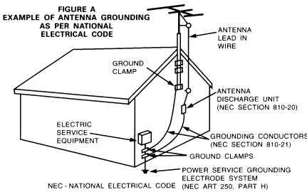
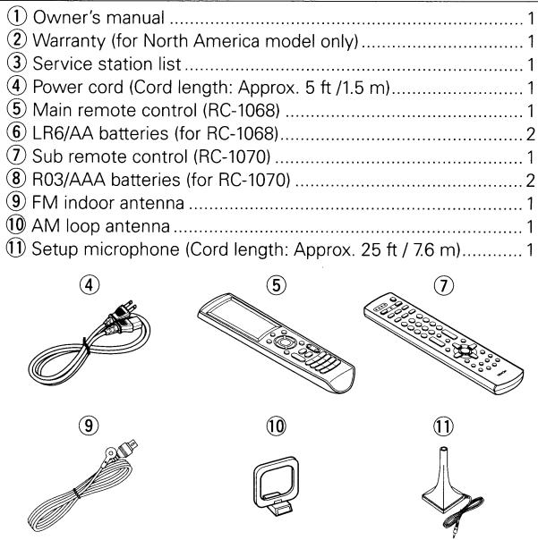
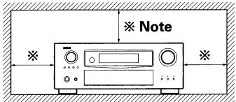
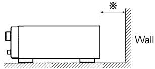
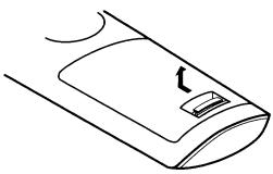
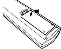
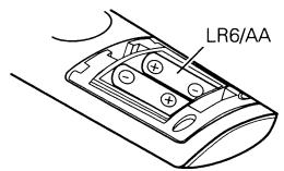
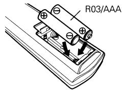
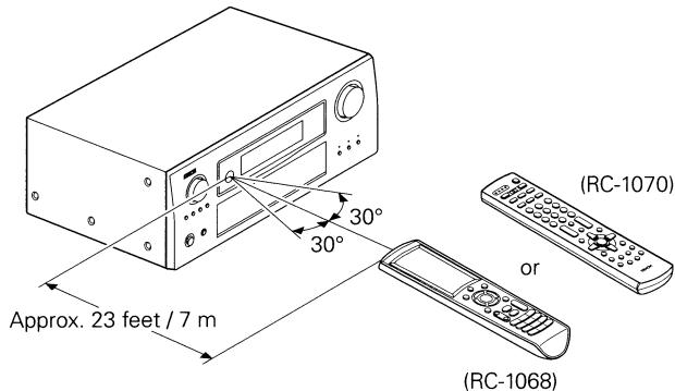
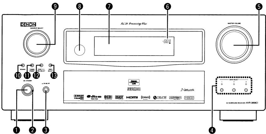

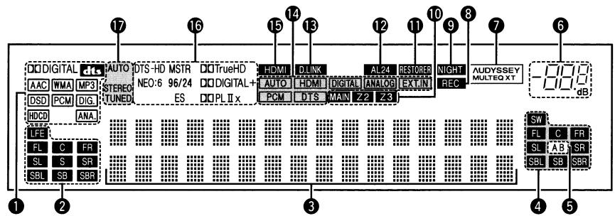
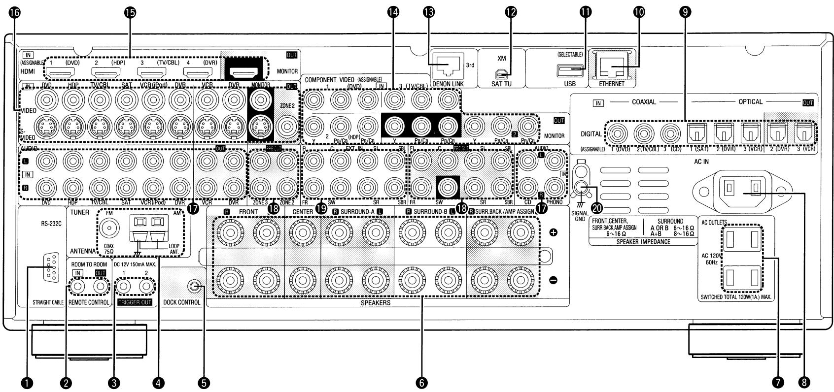
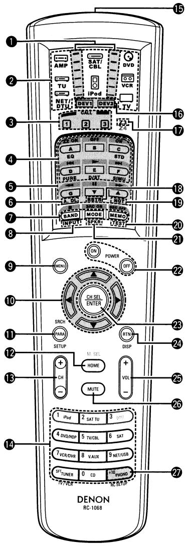

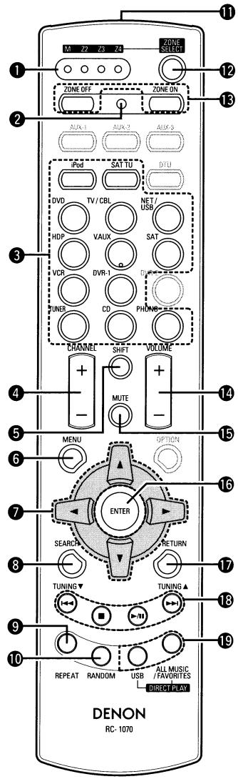
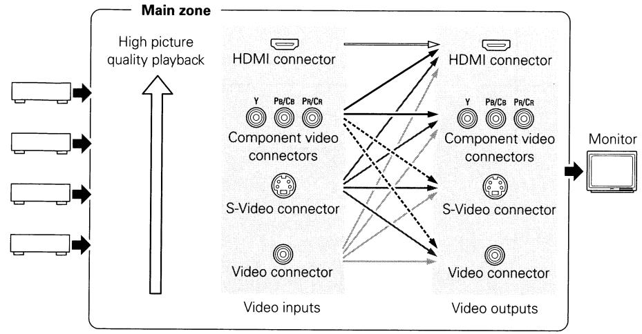
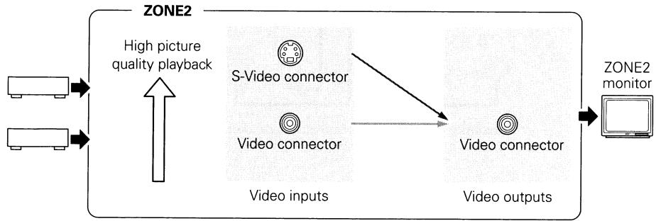

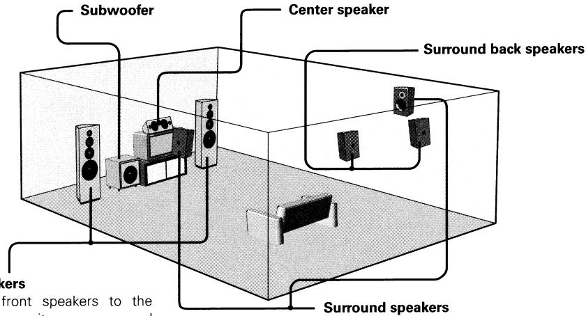

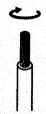

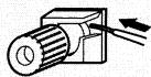
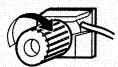
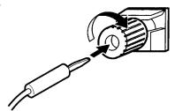
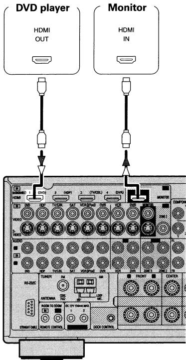


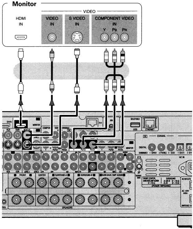
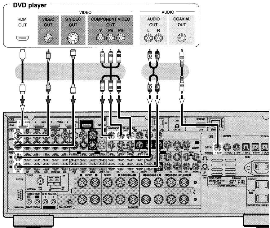

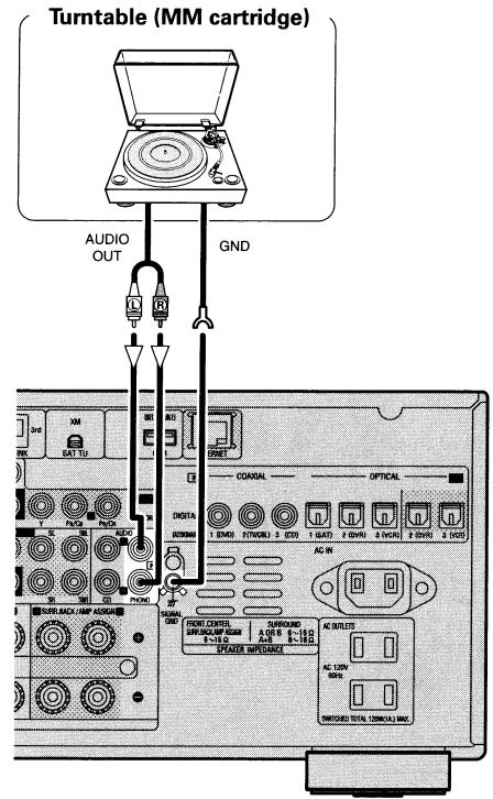

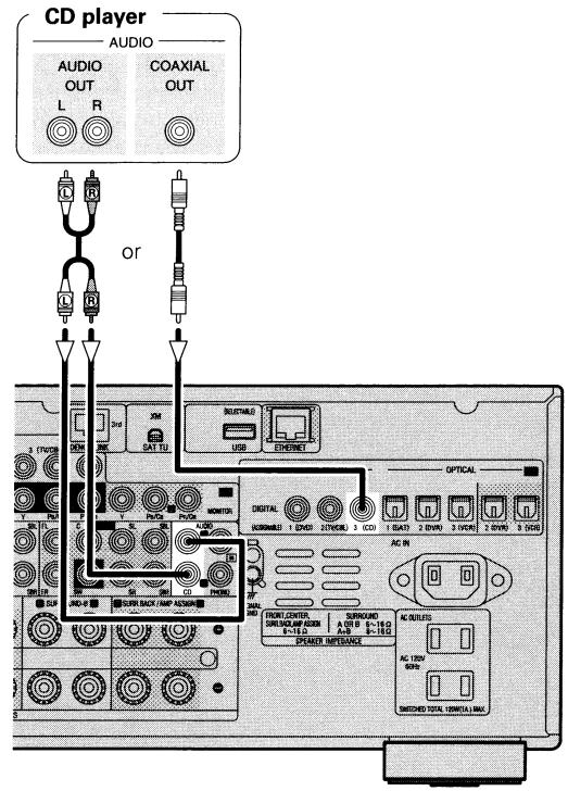

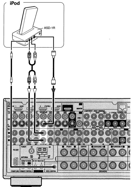

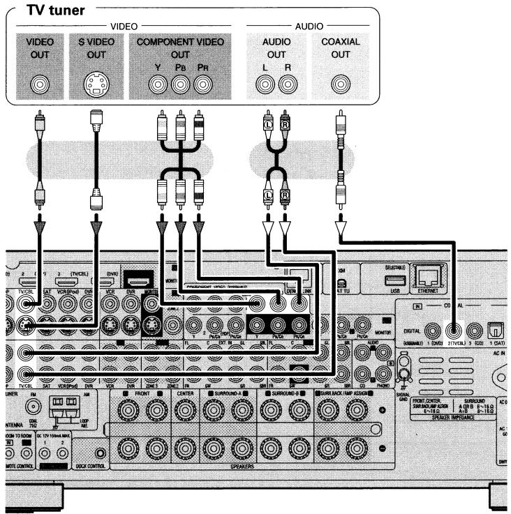

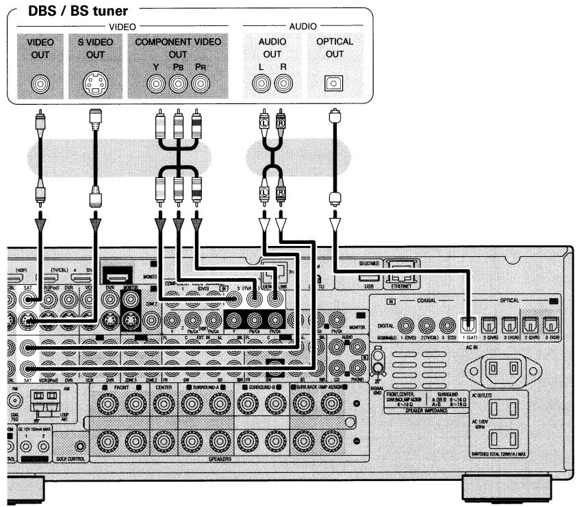

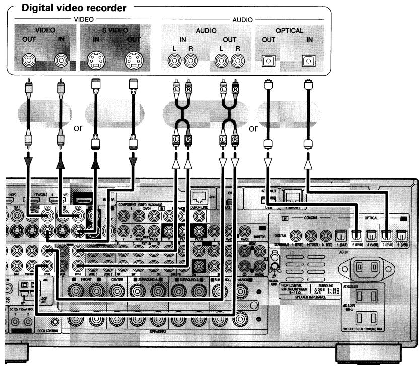

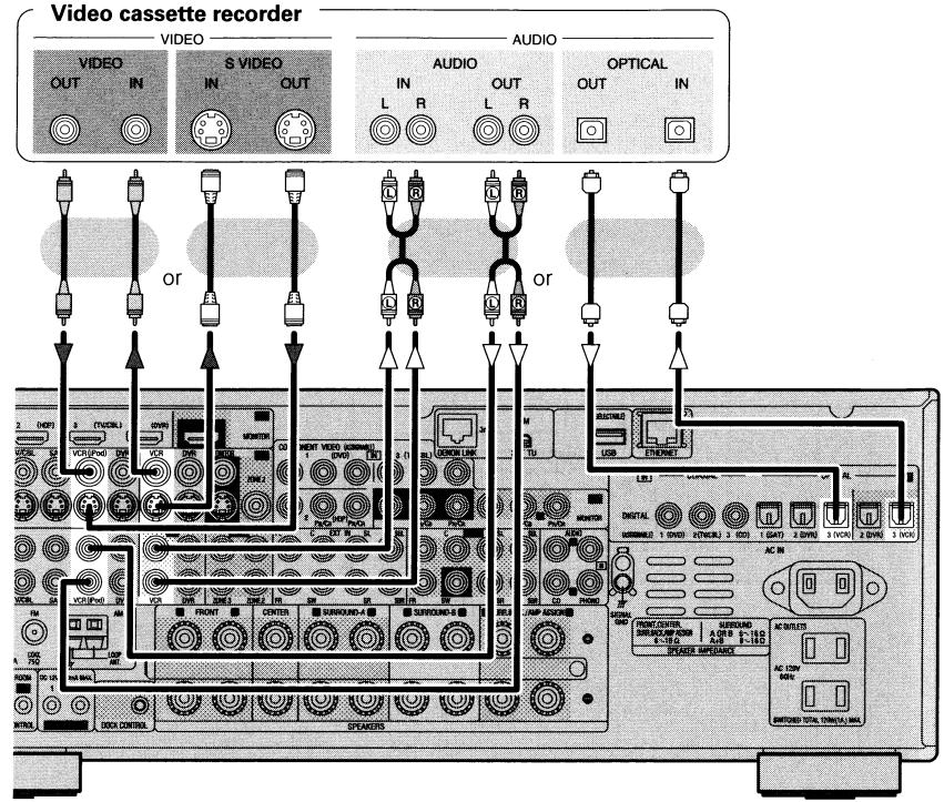

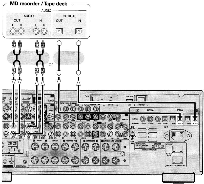
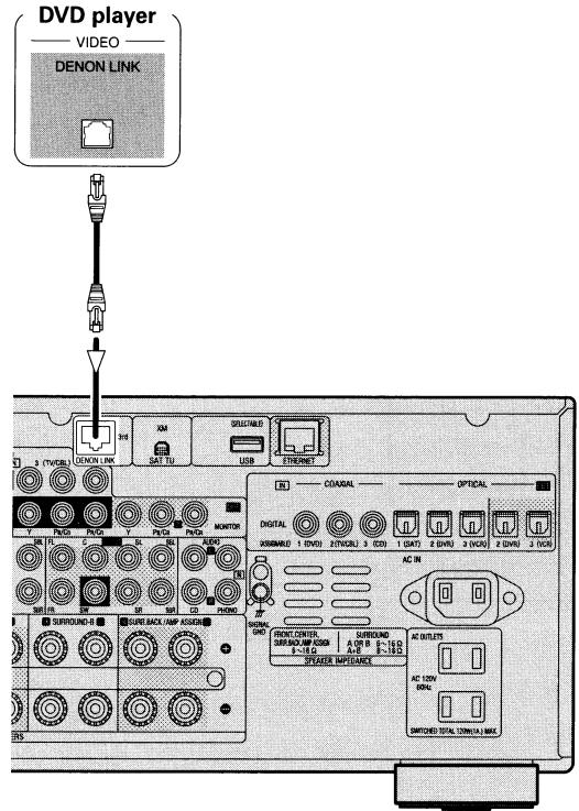

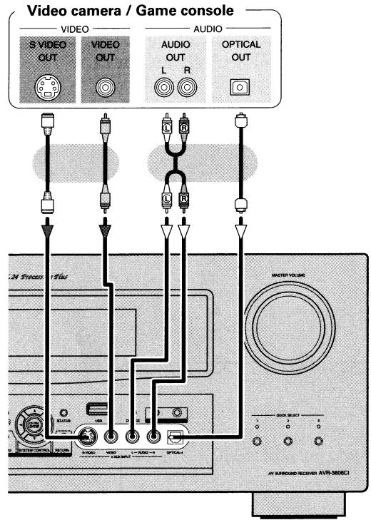
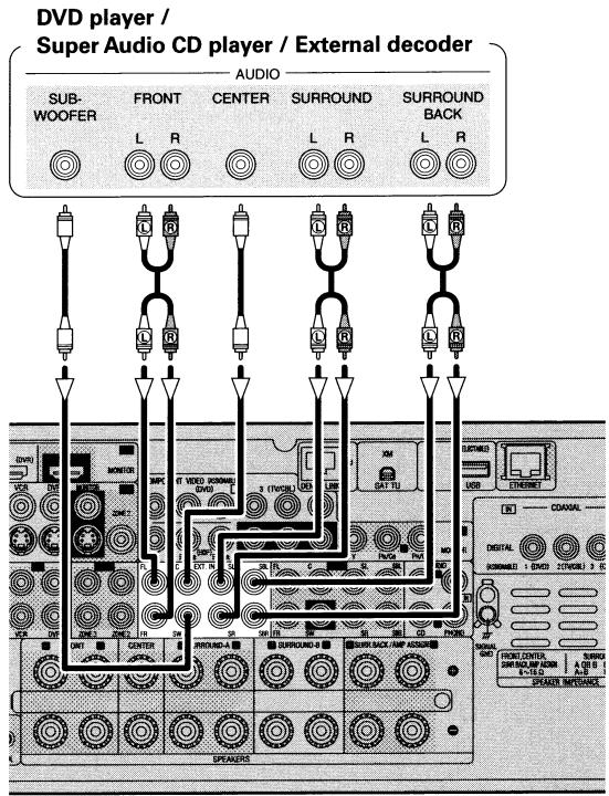

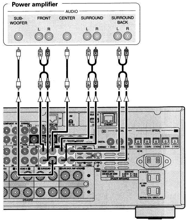

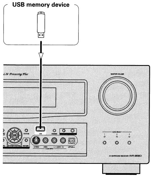
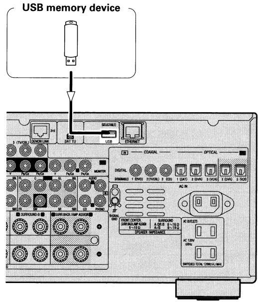

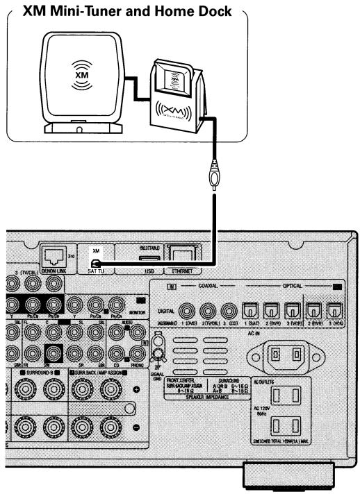
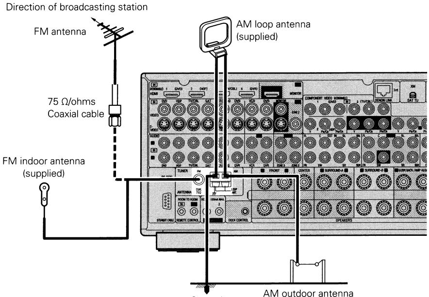
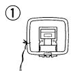

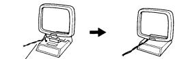
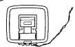
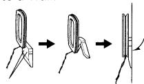
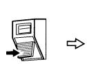
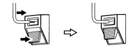
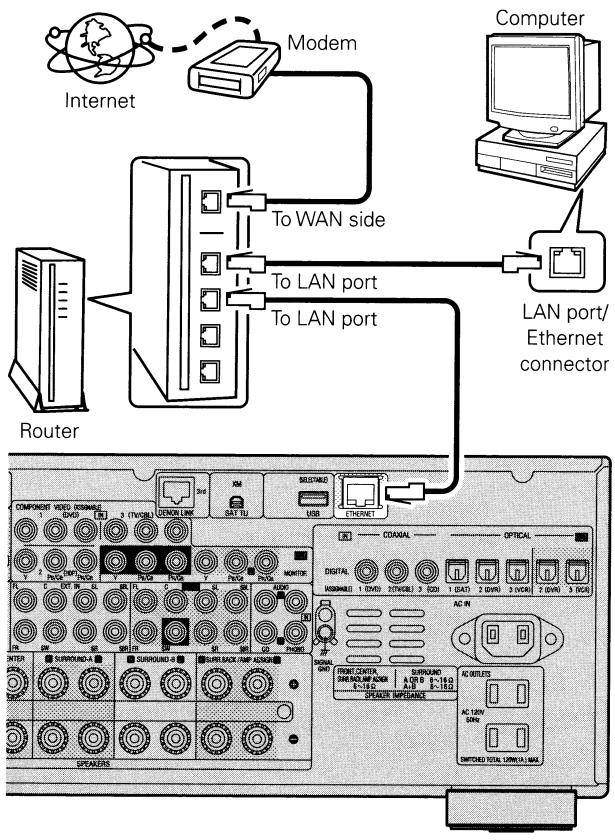

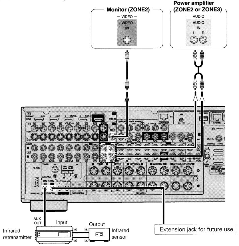
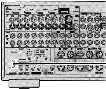

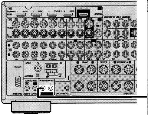
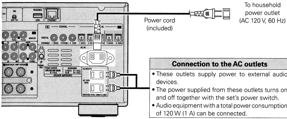


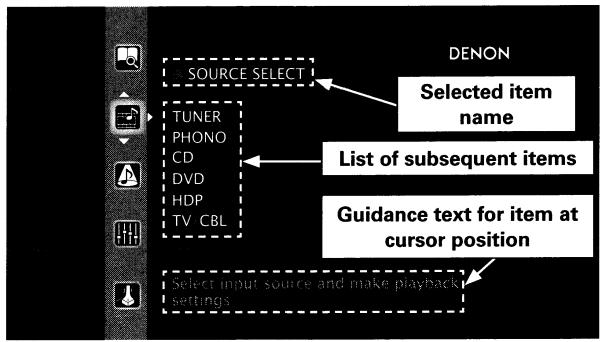
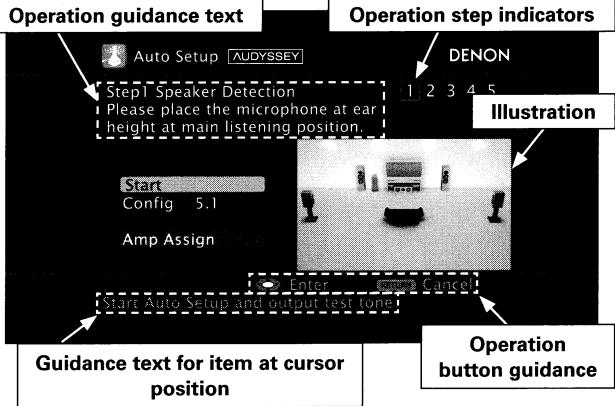
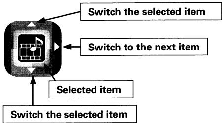
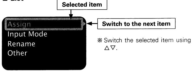





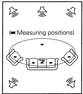
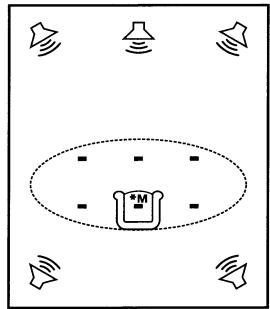

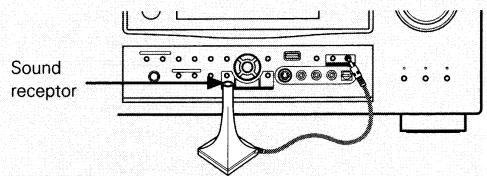
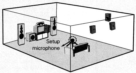

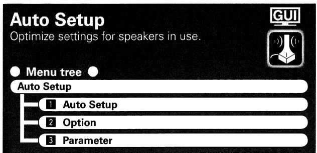
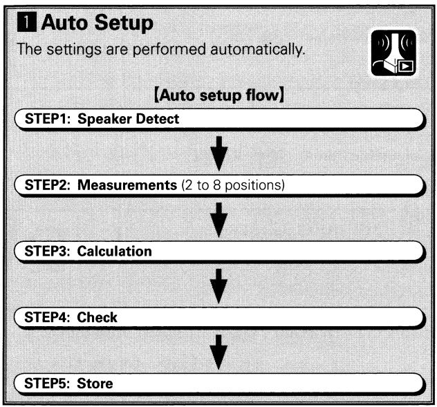


![DENON AVR-3808CI - [Adjusting using test tones] - 1](/content/2024/12/135738/images/8c09204ce38cf92953c09e00ad9a6e8cd2f9cb2e09613ba7e375d37c1a73540a.jpg)
![DENON AVR-3808CI - [Selectable items] - 1](/content/2024/12/135738/images/01be11cd44dae79205ab9dc18958c0622ca85ce035dccf5182fb336190843288.jpg)




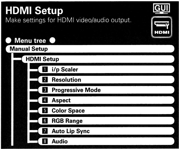


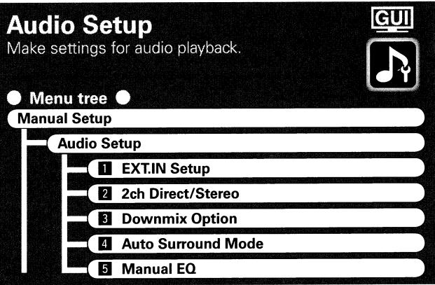

![DENON AVR-3808CI - [Selectable items] - 1](/content/2024/12/135738/images/567da8d4aa1efac7dda5866597f1429d74663e0001f9f151c75df9fe1321ba17.jpg)
![DENON AVR-3808CI - [Selectable items] - 1](/content/2024/12/135738/images/98394b59cbb2449d780867c18f0bdf6ee4e34edde30166e3a1223ffe08c231f0.jpg)

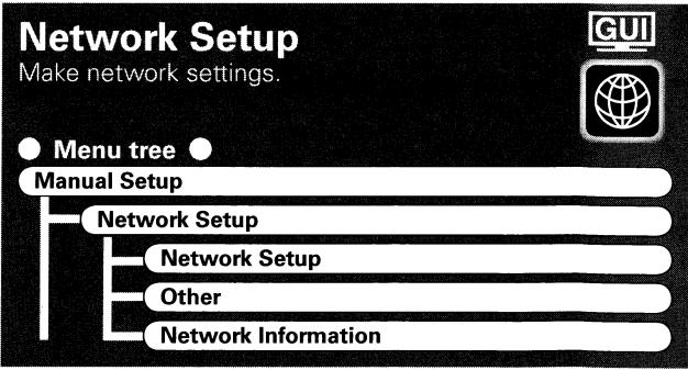
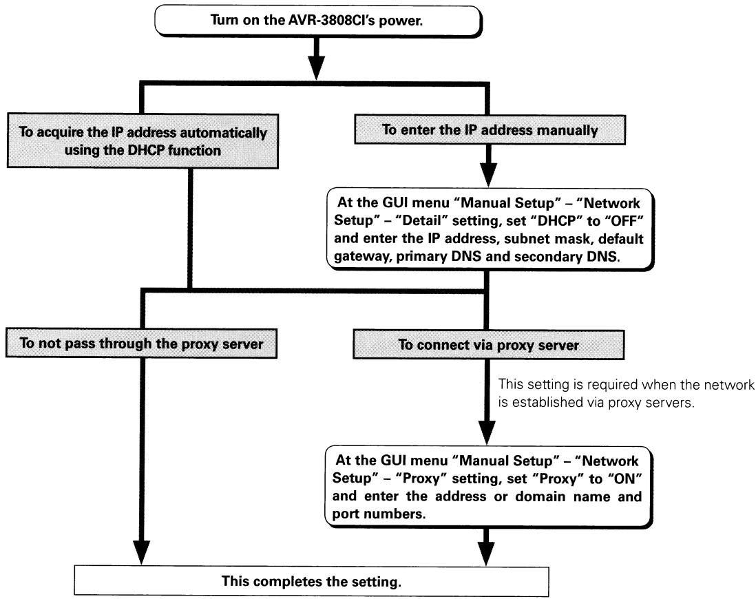


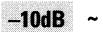

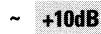
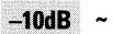

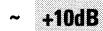
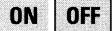
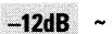

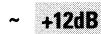


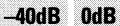





![DENON AVR-3808CI - [Selectable items] - 1](/content/2024/12/135738/images/38e8be17a2bac4e16e51912af296600efddba00704322b6bef0547b2621b4b5a.jpg)










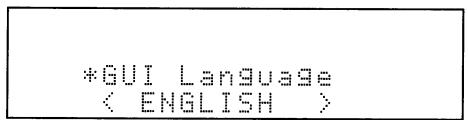
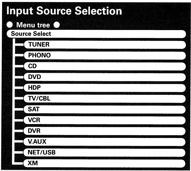

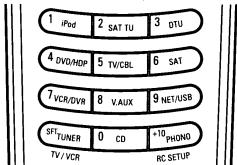

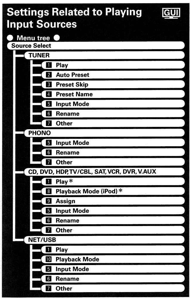
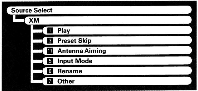
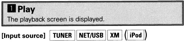





![DENON AVR-3808CI - [Characters that can be input] - 1](/content/2024/12/135738/images/a3879b4abc57d5733af7d67ed09ce05e1250c618597384205b933dbeef6ecbbd.jpg)
![DENON AVR-3808CI - [Selectable items] - 1](/content/2024/12/135738/images/396190564adacd54c586564a932a5be96daeec9c1d86cad530e3b0bcdf304c75.jpg)
![DENON AVR-3808CI - [Selectable items] - 2](/content/2024/12/135738/images/8d59cd78f132f6891156c8d5db62c8ac0b0f8d8e3a29ec00cbcfa55c4f87f500.jpg)


![DENON AVR-3808CI - [Selectable items] - 1](/content/2024/12/135738/images/6bffac8720fea6f5397a36dad69110799ae56ac452d3595354152531661267f9.jpg)





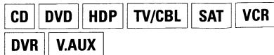


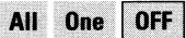
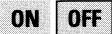


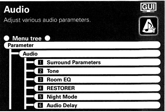
![DENON AVR-3808CI - [Selectable items] - 1](/content/2024/12/135738/images/6e170a1b0a6db727e2611a1bfc3bf0355863783228c717fc1c73ae34f38eefb6.jpg)





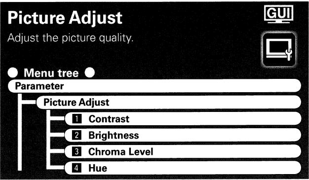


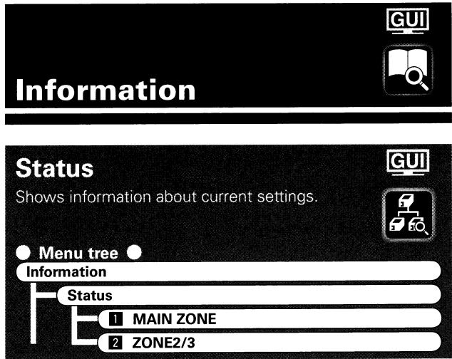
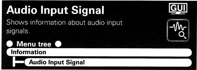
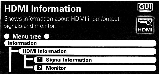


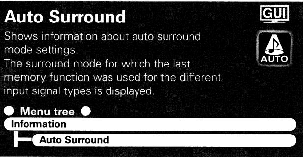
![DENON AVR-3808CI - [Items to be checked] - 1](/content/2024/12/135738/images/6fd6eff961f7ea0bba302cc0a5739f769bde851e8baaf79686f9d6ac8dea84b0.jpg)
![DENON AVR-3808CI - [Items to be checked] - 1](/content/2024/12/135738/images/5671cf16c6dd863adc7c80ed51697c17a402e4a4bec5e77ff5229eed355889b2.jpg)
![DENON AVR-3808CI - [Items to be checked] - 2](/content/2024/12/135738/images/66f568e1b790e1c55faac7694646e5362492219b5bcdc11f8dd71640e552a71e.jpg)
![DENON AVR-3808CI - [Items to be checked] - 3](/content/2024/12/135738/images/e69723888150366439c53e0ac6170edd0758a5da92c957fa019c15deda22e245.jpg)
![DENON AVR-3808CI - [Items to be checked] - 4](/content/2024/12/135738/images/e03557ea570afc9c3943b09b5d0f9b2660e22c85817e5dcf84ac49a2a448896a.jpg)
![DENON AVR-3808CI - [Items to be checked] - 5](/content/2024/12/135738/images/1a24f235fab7f23a3f075ca9f07b1f00cf7cb1d6908c601a55967a9f828e12b3.jpg)
![DENON AVR-3808CI - [Items to be checked] - 6](/content/2024/12/135738/images/c73c32cddd66d19535b4341c0461c7e2525eb6e9a75905f1aa11aca4fa32a4bb.jpg)

![DENON AVR-3808CI - Press [MUTE]. - 1](/content/2024/12/135738/images/ad9244f9bc53c5772e8e72d981f17869e9c8cea6dbbd294fa92cc89d96bdbf97.jpg)
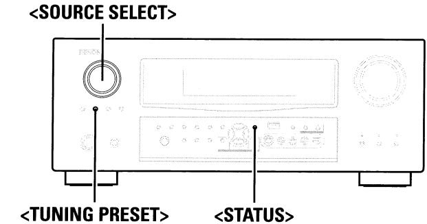
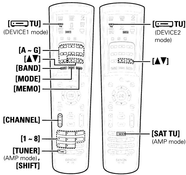




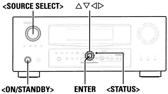
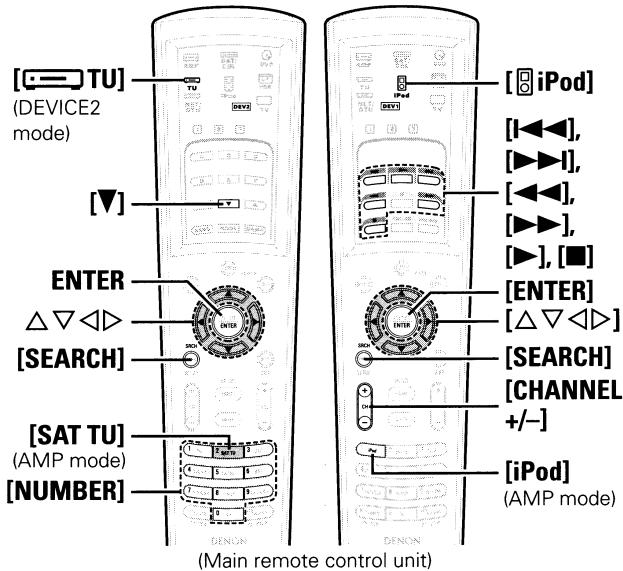
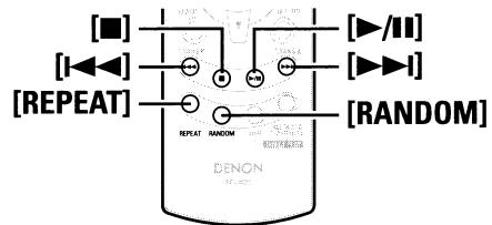



![DENON AVR-3808CI - Either turn or press [iPod] (AMP mode) to select the input source assigned in step 1-② above. - 1](/content/2024/12/135738/images/591d0f162d18d60abf43cc1cd9b7fd9fef1a6e53e21e3961ce8d6ff14a360397.jpg)
![DENON AVR-3808CI - Either turn or press [iPod] (AMP mode) to select the input source assigned in step 1-② above. - 2](/content/2024/12/135738/images/d68857cb3c0d5cbcd3a4ce8aa90b3b46743c5c0076572f08099bd96a213e085a.jpg)

![DENON AVR-3808CI - [Selectable items] - 1](/content/2024/12/135738/images/bbc5da9ab73f5e1309afd9d4d6c7d9bc86614bba483c9e82b3ea76c234a7a9fc.jpg)
![DENON AVR-3808CI - [Selectable items] - 2](/content/2024/12/135738/images/1b13e30f2eb30c77b8b37218add81838d01c30fe626733119f8b0e7ba73ff294.jpg)
![DENON AVR-3808CI - [Selectable items] - 3](/content/2024/12/135738/images/8e821086351ba61a8758e05122c845f86ea73d8e5ef101fe019eddbc158da898.jpg)
![DENON AVR-3808CI - [Selectable items] Albums Songs OFF - 1](/content/2024/12/135738/images/f741bb1d105c70c7414bd71c381af17e47bfad73441e16b0b2a73209105c4f41.jpg)


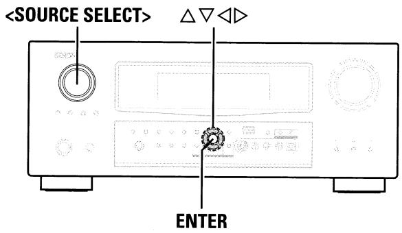
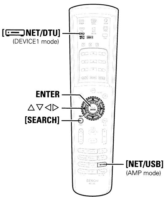


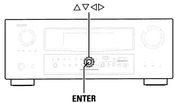
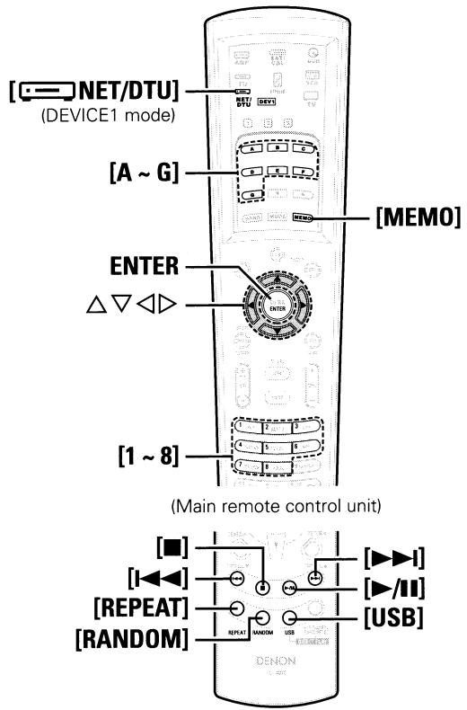


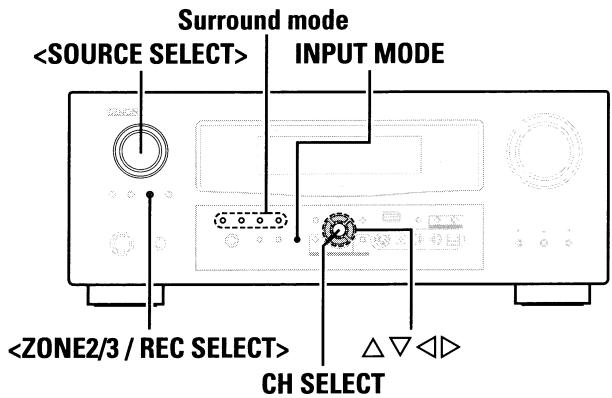
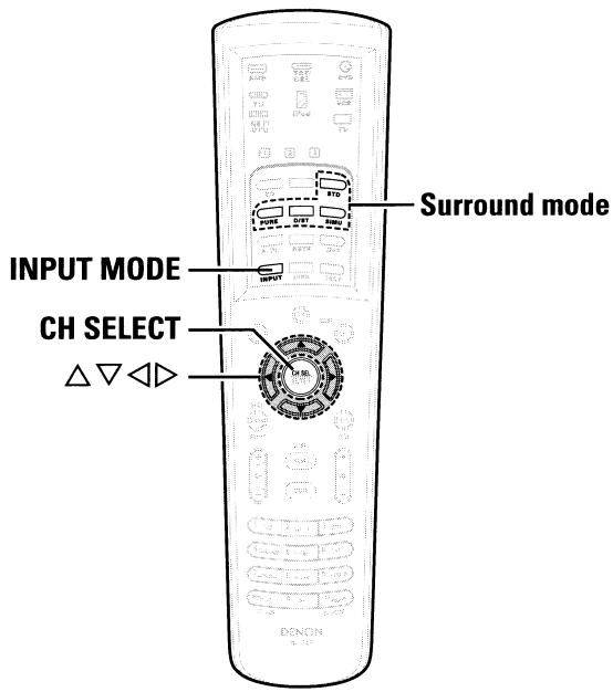





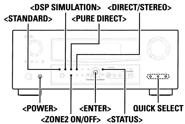
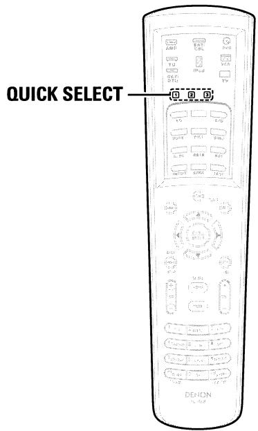


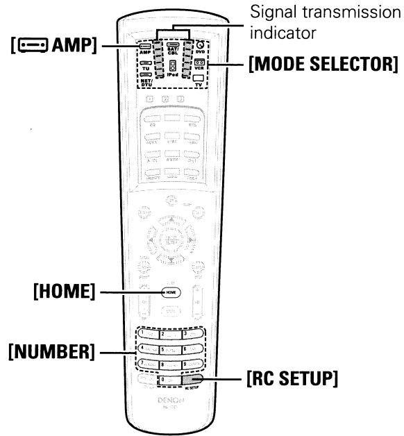
![DENON AVR-3808CI - Press [MODE SELECTOR] for the component to be operated. - 1](/content/2024/12/135738/images/cd6c993f56022271cf61d5d083c1ff8cb3ac4c0a90fdac10bea0e5cae80e57d2.jpg)
![DENON AVR-3808CI - Press [MODE SELECTOR] for the component to be operated. - 2](/content/2024/12/135738/images/2277fe25881fd5092cf3fbc1b5d0f646411be4a5606524d6f0bb6cdf2d7b5858.jpg)

![DENON AVR-3808CI - Press [NUMBER] and input the 5-digit number of the brand of the component to be preset. The numbers are shown in the Preset Code Table (End of the this manual). - 1](/content/2024/12/135738/images/d68306d29d74ccd24f00a0081b9aa40592bd2f5d2d4d718a4352d6bb61a2060e.jpg)

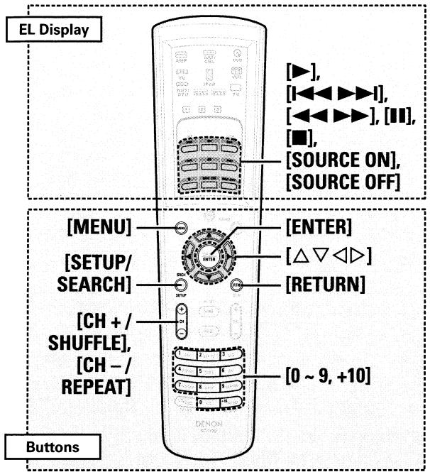
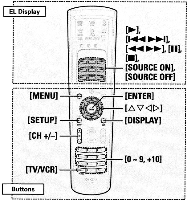
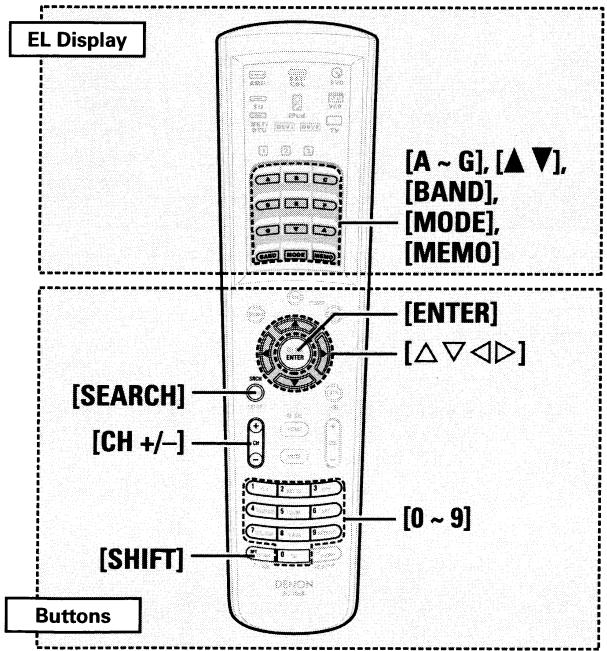
![DENON AVR-3808CI - [Special Remarks] - 1](/content/2024/12/135738/images/7755de35f5f8979cd8fb7d3dcdc5990c72e5891282d1c20ce1dd9ec8b36d4b68.jpg)
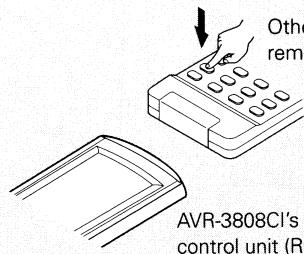

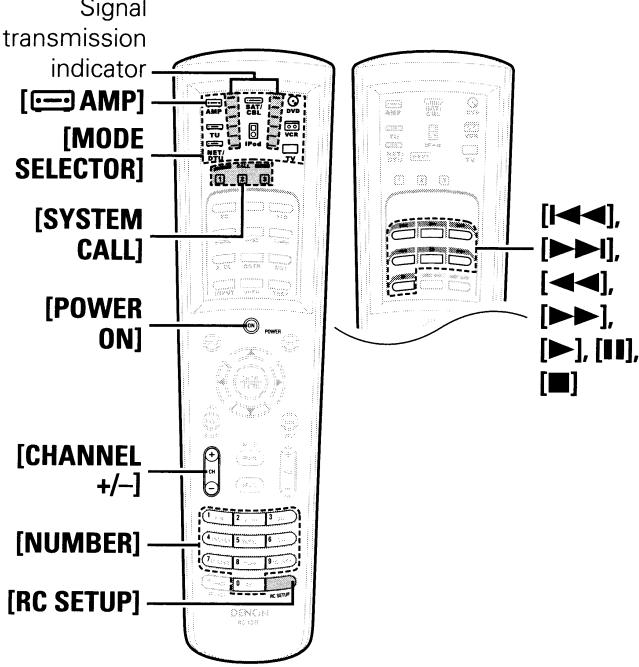
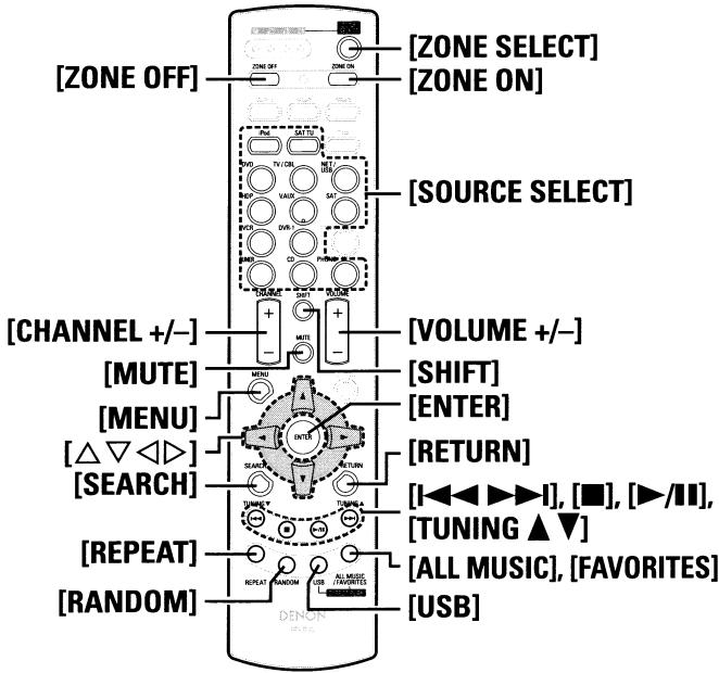
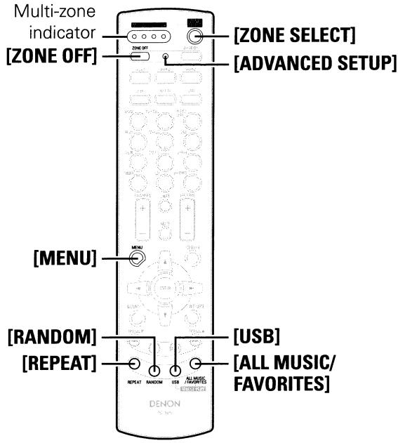

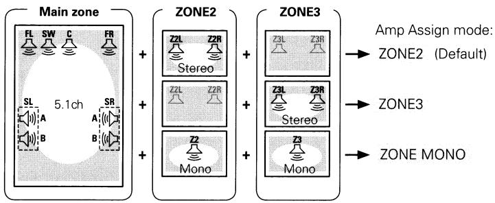

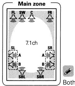
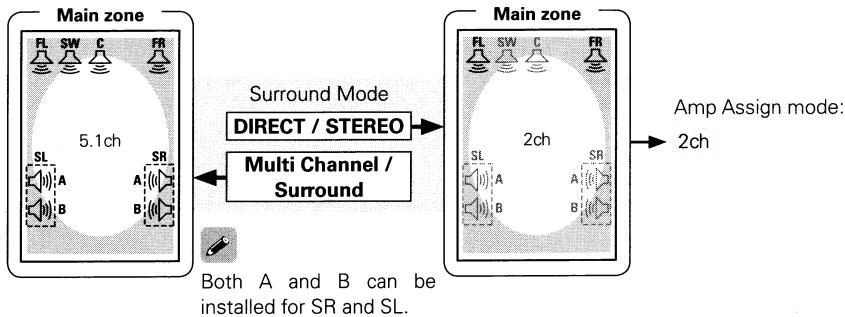
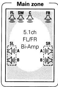
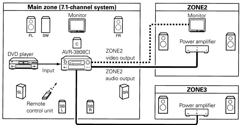

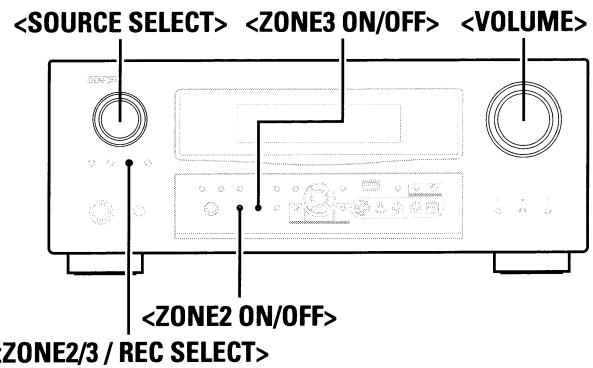
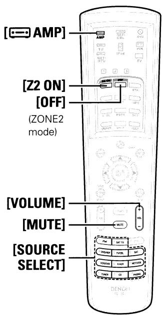
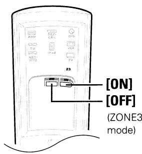
![DENON AVR-3808CI - [Operation on the main remote control unit] - 1](/content/2024/12/135738/images/e991fdf75ebf4bfd11eb536b6212a9dd1264fc7661dacb88a847be1734dc0a51.jpg)

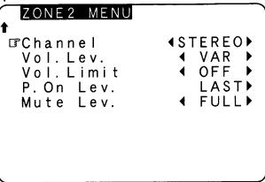
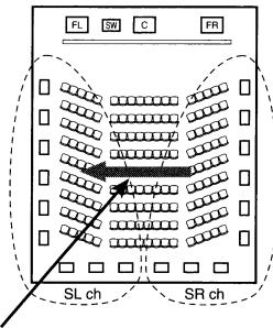
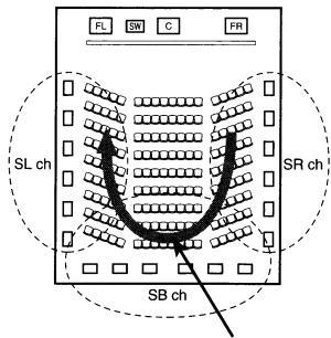
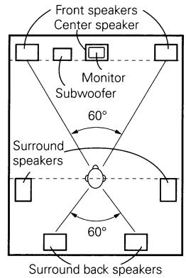
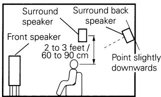
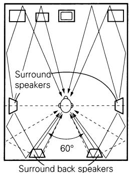
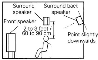
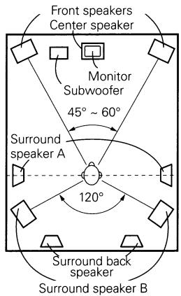
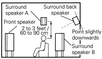
![DENON AVR-3808CI - [2] When not using surround back speakers - 1](/content/2024/12/135738/images/eea939fd03ddd3ca2cdecfd5e6e78fd76ee5584044e8ff6c15237fce4e3c4c78.jpg)
![DENON AVR-3808CI - [2] When not using surround back speakers - 2](/content/2024/12/135738/images/d0515ffeba73eb55fb5fa48a1b939d47a6419ced99c15192eb4bef7d96f1f00b.jpg)