
PMA-SA1 - Integrated amplifier DENON - Free user manual and instructions
Find the device manual for free PMA-SA1 DENON in PDF.
| Product Type | Integrated Amplifier |
| Brand | Denon |
| Model | PMA-SA1 |
| Dimensions (W x H x D) | 434 x 181 x 508 mm (including feet, controls, and terminals) |
| Weight | 30.0 kg |
| Power Supply | AC 230 V, 50 Hz |
| Power Consumption | 230 W (IEC) |
| Output Power (8 Ω) | 50 W + 50 W (20 Hz - 20 kHz, 0.07 % THD) |
| Output Power (4 Ω) | 100 W + 100 W (1 kHz, 0.7 % THD) |
| Total Harmonic Distortion | 0.007 % (at -3 dB of rated output, 8 Ω, 1 kHz) |
| Inputs | Phono (MM), CD-1, CD-2, Tuner, DVD/AUX, TAPE-1/CD-R, TAPE-2/MD, Balanced (XLR) |
| Outputs | Speakers (4-16 Ω), REC OUT (TAPE-1/CD-R, TAPE-2/MD) |
| Input Sensitivity (Phono) | 2.5 mV / 47 kΩ |
| Input Sensitivity (Others) | 105 mV / 47 kΩ |
| Input Sensitivity (Balanced) | 105 mV / 100 kΩ |
| Signal-to-Noise Ratio (Phono) | 88 dB (IHF A, inputs short-circuited, 5 mV) |
| Signal-to-Noise Ratio (Others) | 105 dB (IHF A, inputs short-circuited) |
| Phono Equalizer | Switchable (EQ POWER), RIAA correction ±0.3 dB (20 Hz - 20 kHz) |
| Special Features | Balanced input, REC OUT selector, quick protection circuit |
| Supplied Accessories | Owner's manual, power cord, list of authorized service stations |
Frequently Asked Questions - PMA-SA1 DENON
User questions about PMA-SA1 DENON
0 question about this device. Answer the ones you know or ask your own.
Ask a new question about this device
Download the instructions for your Integrated amplifier in PDF format for free! Find your manual PMA-SA1 - DENON and take your electronic device back in hand. On this page are published all the documents necessary for the use of your device. PMA-SA1 by DENON.
USER MANUAL PMA-SA1 DENON
INTEGRATED STEREO AMPLIFIER
PMA-SA1
OPERATING INSTRUCTIONS
TO PREVENT FIRE OR SHOCK HAZARD, DO NOT EXPOSE THIS APPLIANCE TO RAIN OR MOISTURE.
"SERIAL NO.
PLEASE RECORD UNIT SERIAL NUMBER ATTACHED TO THE REAR OF THE CABINET FOR FUTURE REFERENCE"

CAUTION RISK OF ELECTRIC SHOCK DO NOT OPEN

CAUTION: TO REDUCE THE RISK OF ELECTRIC SHOCK, DO NOT REMOVE COVER (OR BACK). NO USER-SERVICEABLE PARTS INSIDE. REFER SERVICING TO QUALIFIED SERVICE PERSONNEL.

The lightning flash with arrowhead symbol, within an equilateral triangle, is intended to alert the user to the presence of uninsulated "dangerous voltage" within the product's enclosure that may be of sufficient magnitude to constitute a risk of electric shock to persons.

The exclamation point within an equilateral triangle is intended to alert the user to the presence of important operating and maintenance (servicing) instructions in the literature accompanying the appliance.
- DECLARATION OF CONFORMITY
We declare under our sole responsibility that this product, to which this declaration relates, is in conformity with the following standards:
EN60065, EN55013, EN55020, EN61000-3-2 and EN61000-3-3.
Following the provisions of 73/23/EEC, 89/336/EEC and 93/68/EEC Directive.
* (For sets with ventilation holes)
- Do not obstruct the ventilation holes.
Die Belüftungsöffnungen können nicht verdeckt werden. - Ne pas obstruer les trouès d'aération.
Non coprite i fori di ventilazione. - No obtruya los orificios de ventilación.
- De ventilatieopengen mogen nicht worden beblokkeerd.
Tappinte tillventilationsoppningarna.

- Do not let foreign objects in the set.
- Keine fremden Gegenstände in das Gerätkommen halten.
- Ne pas laisser des objets étrangers dans l'appareil.
- E' importante che nessun oggetto è inserto all'interno dell'unità.
- NoADEjebotontrasnoidtrodelequipo.
- Laat geen vreemde voorwerpen in dit apparaat vallen.
- Se till att främande foremål inte tränger in i apparaten.

- Do not let insecticides, benzene, and thinner come in contact with the set.
- Lassen Sie das Gerät nicht mit Insektiziden, Benzin oder Verdünningsmitteln in Berührung kommt.
- Ne pasmettre en contact des insecticides,du benzene et un diluant avec I'appareil.
- Assicuratevvi che l'unità non venga in contatto con insetticidi, benzolo o solventi.
- No permitted contacto de insecticidas, gasolina y diluyentes con el equipo.
- Laat geen insetkenverdelgende middelen, benzine of verfverdunner met dit apparaat in contact komen.
- Se till att inte insetktsmedel på spraybruk, bensen och thinnerkommen i kontakt med apparatens höje.

- Never disassemble or modify the set in any way.
Versuchen Sie niemals das Gerät auseinander zunehmen oder auf jegliche Art zu verändern. - Ne jamais démonter ou modifier l'appareil d'une manière ou d'une autre.
Non smontate mai, nè modificate l'unità in nessun modo. - Nunca desarme o modifique el equipo de ninguna manera.
- Nooit dit apparaat demonteren of op andere wijze modifierten.
- Ta inte isär apparaten och försök inte bygga om den.
CAUTION
- The ventilation should not be impeded by covering the ventilation openings with items, such as newspapers, tablecloths, curtains, etc.
-
No naked flame sources, such as lighted candles, should be placed on the apparatus.
-
Please be care the environmental aspects of battery disposal.
- The apparatus shall not be exposed to dripping or splashing for use.
- No objects filled with liquids, such as vases, shall be placed on the apparatus.
NOTE:
Unplug the power supply cord when you do not plan to use the unit for a long period of time.
TABLE OF CONTENTS
1 DESIGNATIONS AND FUNCTIONS OF PANEL CONTROLS. 5 ~ 7
2 CONNECTIONs. 8,9
3 OPERATION 10
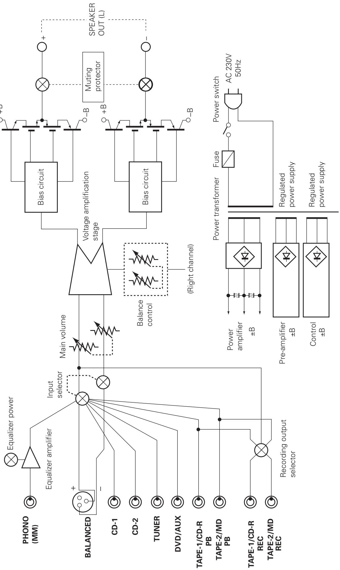
4 BLOCK DIAGRAM 11
5TROUBLESHOOTING 12
6 SPECIFICATIONS 13
Please check to make sure the following items are included with the main unit in the carton:
(1) Operating Instructions 1
(2) Power Supply Cord 1
(3) Service Station List. 1
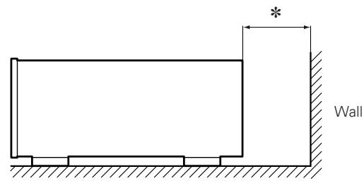
PRECAUTIONS FOR INSTALLATION
Note:
For heat dispersal, do not install this equipment in a confinedspace such as a book case or similar unit.
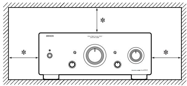
* Note
1 DESIGNATIONS AND FUNCTIONS OF PANEL CONTROLS
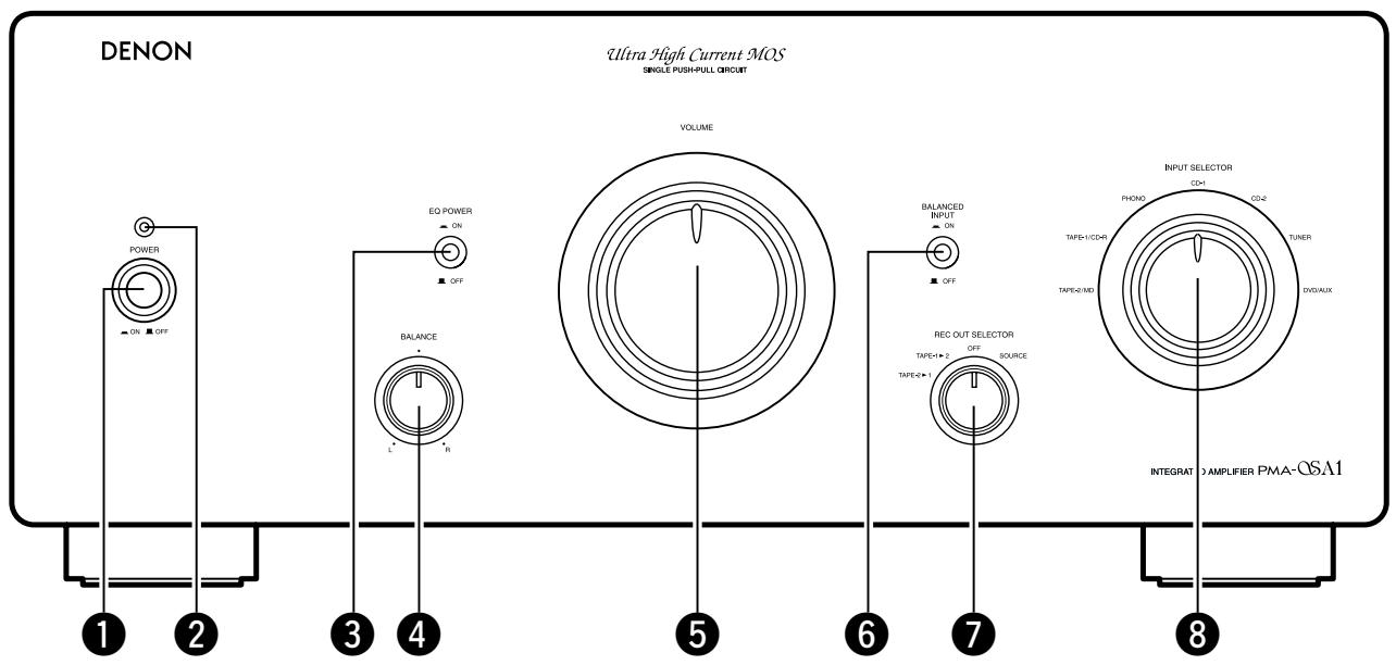
FRONT PANEL
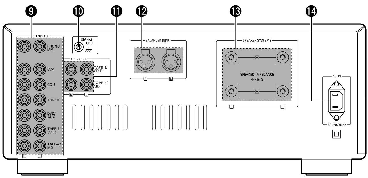
REAR PANEL
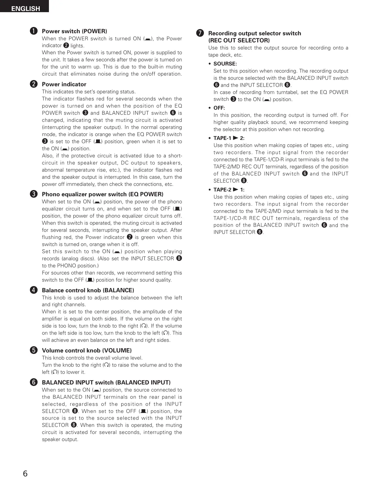
Power switch (POWER)
When the POWER switch is turned ON (—), the Power indicator ② lights.
When the Power switch is turned ON, power is supplied to the unit. It takes a few seconds after the power is turned on for the unit to warm up. This is due to the built-in muting circuit that eliminates noise during the on/off operation.
Power indicator
This indicates the set's operating status.
The indicator flashes red for several seconds when the power is turned on and when the position of the EQ POWER switch 3 and BALANCED INPUT switch 6 is changed, indicating that the mating circuit is activated (interrupting the speaker output). In the normal operating mode, the indicator is orange when the EQ POWER switch 3 is set to the OFF (■) position, green when it is set to the ON (—) position.
Also, if the protective circuit is activated (due to a short-circuit in the speaker output, DC output to speakers, abnormal temperature rise, etc.), the indicator flashes red and the speaker output is interrupted. In this case, turn the power off immediately, then check the connections, etc.
3 Phono equalizer power switch (EQ POWER)
When set to the ON (—) position, the power of the phono equalizer circuit turns on, and when set to the OFF (■) position, the power of the phono equalizer circuit turns off. When this switch is operated, the muting circuit is activated for several seconds, interrupting the speaker output. After flushing red, the Power indicator ② is green when this switch is turned on, orange when it is off.
Set this switch to the ON (—) position when playing records (analog discs). (Also set the INPUT SELECTOR 8 to the PHONO position.)
For sources other than records, we recommend setting this switch to the OFF (■) position for higher sound quality.
4 Balance control knob (BALANCE)
This knob is used to adjust the balance between the left and right channels.
When it is set to the center position, the amplitude of the amplifier is equal on both sides. If the volume on the right side is too low, turn the knob to the right () . If the volume on the left side is too low, turn the knob to the left () . This will achieve an even balance on the left and right sides.
Volume control knob (VOLUME)
This knob controls the overall volume level.
Turn the knob to the right () to raise the volume and to the left () to lower it.
BALANCED INPUT switch (BALANCED INPUT)
When set to the ON (■) position, the source connected to the BALANCED INPUT terminals on the rear panel is selected, regardless of the position of the INPUT SELECTOR 8. When set to the OFF (■) position, the source is set to the source selected with the INPUT SELECTOR 8. When this switch is operated, the muting circuit is activated for several seconds, interrupting the speaker output.
7 Recording output selector switch (REC OUT SELECTOR)
Use this to select the output source for recording onto a tape deck, etc.
SOURSE:
Set to this position when recording. The recording output is the source selected with the BALANCED INPUT switch 6 and the INPUT SELECTOR 8.
In case of recording from turntable, set the EQ POWER switch 3 to the ON (1) position.
OFF:
In this position, the recording output is turned off. For higher quality playback sound, we recommend keeping the selector at this position when not recording.
- TAPE-1▶2:
Use this position when making copies of tapes etc., using two recorders. The input signal from the recorder connected to the TAPE-1/CD-R input terminals is fed to the TAPE-2/MD REC OUT terminals, regardless of the position of the BALANCED INPUT switch 6 and the INPUT SELECTOR 8.
- TAPE-2 1:
Use this position when making copies of tapes etc., using two recorders. The input signal from the recorder connected to the TAPE-2/MD input terminals is fed to the TAPE-1/CD-R REC OUT terminals, regardless of the position of the BALANCED INPUT switch 6 and the INPUT SELECTOR 8.
Input selector switch (INPUT SELECTOR)
Use these to select the program source.
- TAPE-2/MD:
Use this position when using the tape deck, etc., connected to the TAPE-2/MD terminals.
- TAPE-1/CD-R:
Use this position when using the tape deck, etc., connected to the TAPE-1/CD-R terminals.
PHONO:
Use this position when using the record player connected to the PHONO terminals.
NOTE:
Set the EQ POWER switch ③ to the ON (—) position.
CD-1:
Used to listen a CD player or other component that is connected to the CD-1 terminals.
CD-2:
Used to listen a CD player or other component that is connected to the CD-2 terminals.
TUNER:
Used to play a component such as an FM/AM tuner or a TV tuner that is connected to the TUNER terminals.
DVD/AUX:
Used to play a component such as a HiFi video player, TV tuner or tape deck that is connected to the DVD/AUX terminals.
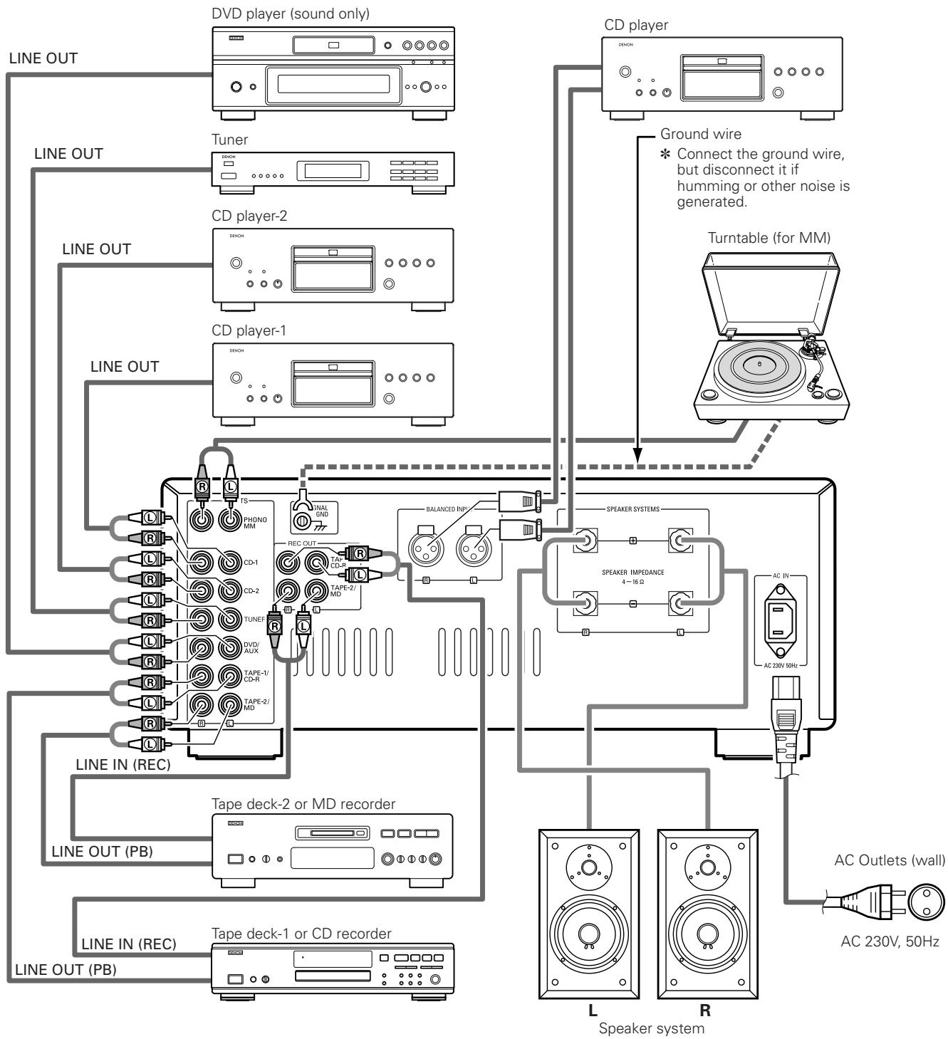
9 Input terminals (INPUTS)
These are input terminals for CD players, turntables, AM/FM tuners, tape decks or other playback components.
NOTE:
The PHONO input terminals are equipped with a short pin-plug. Remove this plug to connect a record player. Store the removed short pin-plug in a safe place so as not to lose it.
10 Ground terminal (SIGNAL GND)
Connect the turntable's ground wire here.
NOTE:
This terminal is used to reduce noise when a turntable, etc., is connected. It does not provide grounding.
1 Recording output terminals (REC OUT)
These are recording output terminals for connection to tape decks or other recorders.
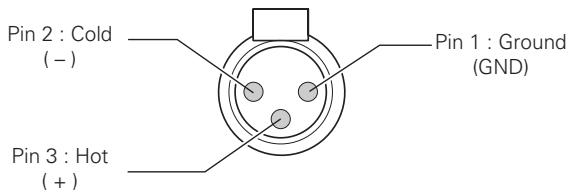
12 BALANCED INPUT terminals (BALANCED INPUT)
These are cannon input terminals for connecting a CD player or other playback component equipped with balanced outputs. The polarities of the pins are as follows:
13 Speaker system terminals (SPEAKER SYSTEMS)
Connect the speaker systems here.
NOTE:
The PMA-SA1's speaker output has a BTL configuration, so inverted phase signal is fed to the “ ” terminal same as noninverted phase signal is fed to the “ ” terminal. Do not use these terminals to connect a device (such as an audio channel selector) for switching between multiple amplifiers or for any type of connection (speaker matrix connection, etc.) other than the normal speaker connections (see page 9). Such connections may result in damage.
14 AC inlet receptacle (AC IN)
Connect the included power supply cord here.
Do not use any other cord than the provided power supply cord.
2 CONNECTIONS
Connecting the speakers
- Speaker impedance
- Use speakers with an impedance of 4 to 16/ ohms.
- The protective circuit may be activated if speakers with other impedances are connected.
- Be sure to connect the cords between the speaker terminals and speaker systems with the same polarities (⊕ to ⊕, ⊙ to ⊙). If not, the central sound will be weak and the position of the different instruments will not be clear, diminishing the stereo effect.
- When connecting the speakers, be sure that the conductors of the speaker cords do not stick out from the terminals and touch other terminals, each other or the rear panel.
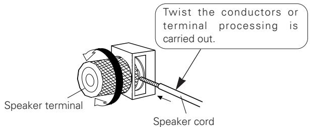
- Connecting the speaker cords
① Peel off the sheathing from the end of the cord.
② Twist the conductors.
③ Turn the speaker terminal counterclockwise to loosen it.
④ Insert the conductors of the cord entirely, then turn the terminal clockwise to tighten it.
CAUTION
Protective Circuit
This set is equipped with a high speed protective circuit. This circuit protects the internal circuitry from damage due to large currents flowing when the speaker terminals are not completely connected or when an output is generated by a short circuit. This protective circuit's operation cuts off the output to the speakers. In such a case, be sure to turn the power off and check the connections to the speakers. Then turn the power on again. After muting for several seconds, the set will operate normally.
NOTE:
NEVER touch the speaker terminals when the power is on.
Doing so could result in electric shocks.
Cautions on Connections
- Do not plug in the power supply cord until all connections are completed.
- Be sure to connect the left and right channels properly.
-
Insert the plugs securely. Incomplete connections can result in noise.
-
The PHONO input terminals have an extremely high sensitivity, so avoid turning up the volume when no pin plug cords are connected. Doing so may result in induction humming (booming) from the speakers. When pin plug cords are not connected, insert the included short-circuit pin plug.
3 OPERATION (Refer to page 5.)
PREPARATION
1. CHECKING CONNECTIONS
- Make sure that all the connections are proper by referring to the rear panel.
- Check the polarity (positive and negative) of connections, and the directivity of stereo separation (right cord to right channel terminal, and left cord to left channel terminal).
- Check the directivity of pin plug cord connection.
2. SETTING OF EACH KNOB
- Turn the VOLUME knob ⑤ counterclockwise, to minimum position.
After checking the above items, turn on the power, the amplifier is set in the ready mode in a few seconds.
PLAYING A RECORD
- Set the EQ POWER switch 3 to "ON".
- Set the INPUT SELECTOR switch 8 to "PHONO".
- Operate the turntable and play the record.
- Turn the VOLUME knob 5 to yield an appropriate volume.
PLAYING CD PLAYER
- Set the INPUT SELECTOR switch 8 to "CD-1".
- Operate the CD player.
- Turn the VOLUME knob 5 to yield an appropriate volume.
PLAYING CD PLAYER
- Set the INPUT SELECTOR switch 8 to "CD-2".
- Operate the CD player.
- Turn the VOLUME knob 5 to yield an appropriate volume.
RECEPTION OF RADIO PROGRAMS
- Set the INPUT SELECTOR switch ⑧ to "TUNER".
- Operate the tuner to receive a radio program.
- Turn the VOLUME knob 5 to yield an appropriate volume.
PLAYING AUDIO EQUIPMENT CONNECTED TO DVD/AUX TERMINALS
- Set the INPUT SELECTOR switch ⑧ to "DVD/AUX" position.
- Operate the Audio equipment.
- Turn the VOLUME knob 5 to yield an appropriate volume.
PLAYING AUDIO EQUIPMENT CONNECTED TO BALANCED INPUT TERMINALS
- Set the BALANCED INPUT switch 6 to "ON".
- Operate the Audio equipment.
- Turn the VOLUME knob 5 to yield an appropriate volume.
PLAY BACK WITH TAPE DECK
- Set the INPUT SELECTOR switch ⑧ to "TAPE-1/CD-R" or "TAPE-2/MD".
- Operate the tape deck.
- Turn the VOLUME knob 5 to yield an appropriate volume.
RECORDING WITH TAPE DECK
- Set the BALANCED INPUT switch 6 and INPUT SELECTOR switch 8 to the program source you wish to record.
- Set the REC OUT SELECTOR switch ⑦ to "SOURCE".
- Play back the program source.
- Start recording with the component connected to "TAPE-1/CD-R" or "TAPE-2/MD".
COPYING FROM ONE TAPE TO ANOTHER
To copy from TAPE-1/CD-R to TAPE-2/MD, set the REC OUT SELECTOR switch 7 to "TAPE-1 2".
To copy from TAPE-2/MD to TAPE-1/CD-R, set the REC OUT SELECTOR switch 7 to "TAPE-2 1".
TROUBLESHOOTING
Check the following before assuming there is a problem with the set.
1. Are all connections proper?
2. Is the set being operated as described in the operating instructions?
3. Are the speakers and input components being operated properly?
If the set does not seem to be operating properly, check the points listed below. If these points do not apply, the set may be damaged. Turn off the power immediately and contact your store of purchase.
| Symptom | Cause | Measures | Page | |
| Common problems arising when listening to the records, tapes, and FM broadcasts, etc. | Power indicator does not light and no sound is produced when POWER switch is turned on. | • Power supply cord is not connected. | • Check that the cord is plugged in. | 9 |
| Power indicator lights but no sound is produced. | • Speaker cords not properly connected. • INPUT SELECTOR switch is not set to proper position. • VOLUME knob turned down. • Input cords not are properly connected. | • Connect securely. • Set to the proper position. • Set to an appropriate level. • Connect securely. | 8, 9 7, 10 6, 10 9 | |
| Sound is not produced from one side only. | • Speaker cords not properly connected. • Input cords not are properly connected. • Left/right balance improperly adjusted. | • Connect securely. • Connect securely. • Adjust the BALANCE knob. | 8, 9 9 6, 10 | |
| Volume level is different when listening to tuner and records. | • Tuner or record output is different. | • Adjust the tuner output to the turntable's output (if the tuner is equipped with an output control). | - | |
| Positions of instruments inverted for stereo sources. | • Left and right speakers or input cords the inverted. | • Check the left/right connections. | 8, 9 | |
| Problems occurring when playing records. | Sound is not produced. | • EQ POWER swith is not set to "ON". | • Set the EQ POWER swith to "ON". | 6, 10 |
| Booming sound produced when playing records. | • Turntable's ground wire is not connected. • Input cords are not properly connected to PHONO terminals. • Influence from a TV or VCR near the turntable. | • Connect securely. • Connect securely. • Change the position of installation. | 9 9 - | |
| Howling produced when volume is turned up while playing records. | • Turntable and speaker systems are too close. • Floor is soft and vibrates easily. | • Move speaker systems as far away as possible. • Use cushions to absorb the vibrations transmitted from the floor to the speakers. If the turntable does not include insulators, use audio insulators, available in stores. | - - | |
| Sound is distorted. | • Stylus pressure is too light. • Dirt on tip of stylus. • Defective cartridge. | • Apply proper pressure. • Check the tip of the stylus. • Replace the cartridge. | - - - |
6 SPECIFICATIONS
- POWER AMPLIFIER SECTION
| Rated Output Power: | Both channel driven (CD-1 → SP OUT) |
| 50 W + 50 W (8 Ω/ohms load, 20 Hz ~ 20 kHz with 0.07 % T.H.D.) | |
| 100 W + 100 W (4 Ω/ohms load, 1 kHz with 0.7 % T.H.D.) | |
| Total Harmonic Distortion: | 0.007 % (-3 dB at rated output) 8 Ω/ohms load, 1 kHz |
| Output terminals: | Speaker load 4 ~ 16 Ω/ohms |
PRE AMPLIFIER SECTION
| PHONO EQUALIZER Rated Output: 150 mV (REC OUT terminal) |
| Input Sensitivity/Input Impedance: | |
| PHONO (MM) | :2.5 mV/47 kΩ/kohms |
| CD-1, CD-2, TUNER, | 105 mV/47 kΩ/kohms |
| DVD/AUX, | |
| TAPE-1/CD-R, | |
| TAPE-2/MD | |
| BALANCED | :105 mV/100 kΩ/kohms |
| RIAA Deviation: PHONO | :20 Hz ~ 20 kHz ±0.3 dB |
OVERALL CHARACTERISTICS
| SN Ratio (IHF A Network): | PHONO (MM) | :88 dB (input terminals short-circuited, 5 mV input signal) |
| CD-1, CD-2, TUNER, | ||
| DVD/AUX, | ||
| TAPE-1/CD-R, | 105 dB (input terminals short-circuited) | |
| TAPE-2/MD, | ||
| BALANCED |
OTHERS
| Power Supply: | AC 230 V, 50 Hz |
| Power Consumption: | 230 W (IEC) |
| Dimensions: | 434 (W) x 181 (H) x 508 (D) mm (including feet, controls and terminals) |
| Mass: | 30.0 kg |
- Maximum dimensions include controls, terminals, and covers.
(W) = width, (H) = height, (D) = depth
- For improvement purposes, specifications and functions are subject to change without advanced notice.
HINWEIS:
6 Interrupttore BALANCED INPUT (BALANCED INPUT
WEERGAVE MET HET TAPE-DECK
OPNAME MET HET TAPE-DECK
- INTEGRATED STEREO AMPLIFIER
- PMA-SA1
- CAUTION RISK OF ELECTRIC SHOCK DO NOT OPEN
- - DECLARATION OF CONFORMITY
- CAUTION
- NOTE:
- TABLE OF CONTENTS
- Please check to make sure the following items are included with the main unit in the carton:
- PRECAUTIONS FOR INSTALLATION
- DESIGNATIONS AND FUNCTIONS OF PANEL CONTROLS
- Power switch (POWER)
- Power indicator
- Phono equalizer power switch (EQ POWER)
- Balance control knob (BALANCE)
- Volume control knob (VOLUME)
- BALANCED INPUT switch (BALANCED INPUT)
- Recording output selector switch (REC OUT SELECTOR)
- SOURSE:
- OFF:
- - TAPE-1▶2:
- - TAPE-2 1:
- Input selector switch (INPUT SELECTOR)
- - TAPE-2/MD:
- - TAPE-1/CD-R:
- PHONO:
- CD-1:
- CD-2:
- TUNER:
- DVD/AUX:
- Input terminals (INPUTS)
- Ground terminal (SIGNAL GND)
- Recording output terminals (REC OUT)
- BALANCED INPUT terminals (BALANCED INPUT)
- Speaker system terminals (SPEAKER SYSTEMS)
- AC inlet receptacle (AC IN)
- CONNECTIONS
- Connecting the speakers
- Protective Circuit
- Cautions on Connections
- OPERATION (Refer to page 5.)
- PREPARATION
- CHECKING CONNECTIONS
- SETTING OF EACH KNOB
- PLAYING A RECORD
- PLAYING CD PLAYER
- RECEPTION OF RADIO PROGRAMS
- PLAYING AUDIO EQUIPMENT CONNECTED TO DVD/AUX TERMINALS
- PLAYING AUDIO EQUIPMENT CONNECTED TO BALANCED INPUT TERMINALS
- PLAY BACK WITH TAPE DECK
- RECORDING WITH TAPE DECK
- COPYING FROM ONE TAPE TO ANOTHER
- TROUBLESHOOTING
- Check the following before assuming there is a problem with the set.
- Are all connections proper?
- Is the set being operated as described in the operating instructions?
- Are the speakers and input components being operated properly?
- SPECIFICATIONS
- - POWER AMPLIFIER SECTION
- PRE AMPLIFIER SECTION
- OVERALL CHARACTERISTICS
- OTHERS
- HINWEIS:
- Interrupttore BALANCED INPUT (BALANCED INPUT
- WEERGAVE MET HET TAPE-DECK
- OPNAME MET HET TAPE-DECK
Brand : DENON
Model : PMA-SA1
Category : Integrated amplifier